brr 6.8 coslab rating example - louisiana · helpful hints about brr •if you are on a certain tab...
TRANSCRIPT

Helpful hints about BrR
• If you are on a certain tab or data entry field, you can hit the F1 key to bring up the help screen that is specific to that data entry field you are working with
• After you enter data, hit “Apply” to make sure the changes are applied.
• Save often

Bridge Description Data – Description Tab
First, enter the bridge description data under the first field on the bridge workspace-this is the field labeled with a bridge at the top of the tree.
LADOTD uses the following as a standard way to enter the information in the “Description” Tab• Bridge ID – bridge recall number• NBI Structure Number – bridge structure number• Bridge Name – the six letter bridge type such as COSLAB, COPCSS• Description – this should include the date rated, initials of the rater, name of consulting
firm if applicable, standards used if applicable, project number and any other relevant information.
• Other fields are self-explanatory.

Bridge Description Data – Description (cont’d)Tab
On this tab, enter the district, parish (county), owner, and functional class.

Bridge Description Data – Alternatives Tab
On this tab, the Bridge Alternative you defined should be selected. If you have not defined an alternative, we will cover that in a later slide. Every bridge must have at least one alternative.
Bridge Description Data – Traffic Tab
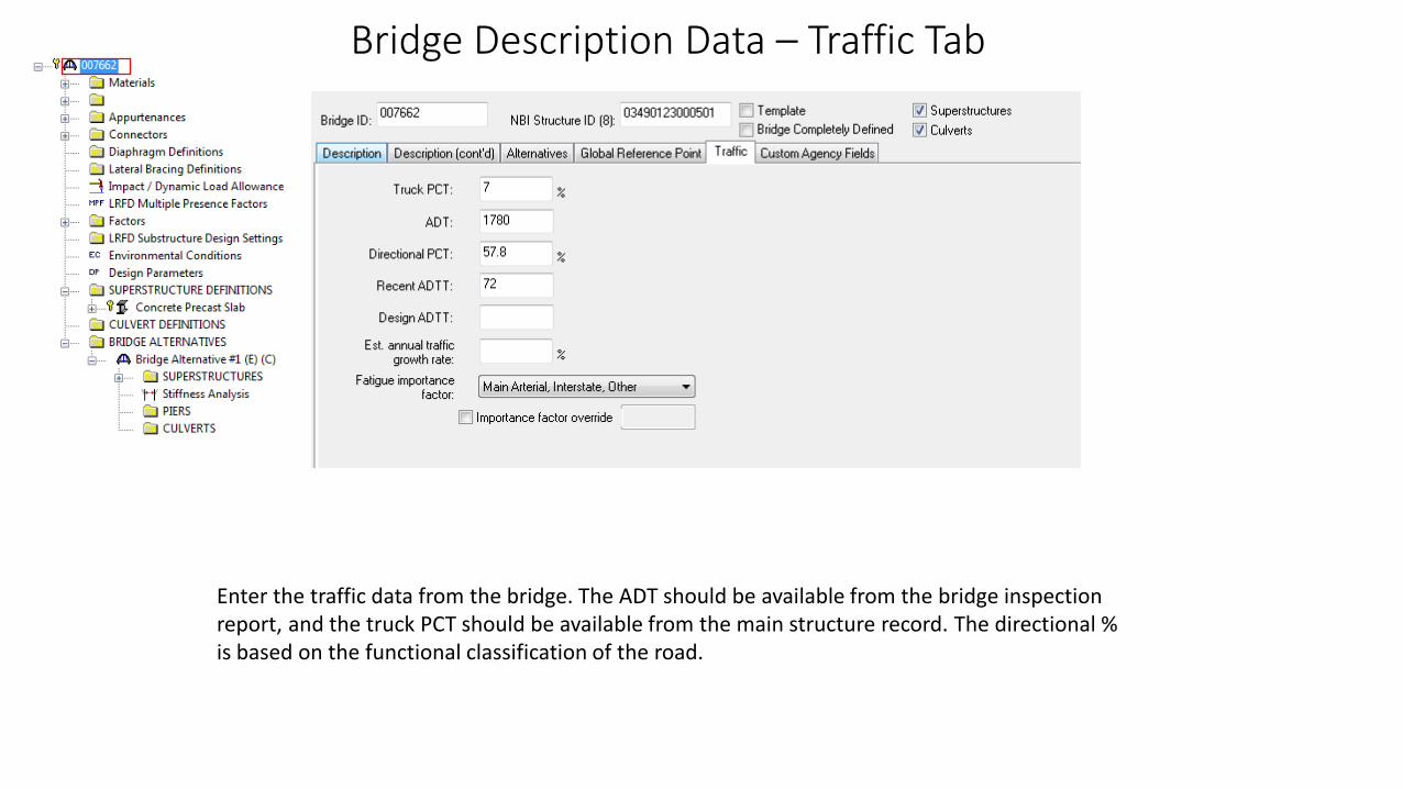
Enter the traffic data from the bridge. The ADT should be available from the bridge inspection report, and the truck PCT should be available from the main structure record. The directional % is based on the functional classification of the road.

Bridge Description Data – Other Tabs
Typically we do not enter data on the “Global Reference Point” or “Custom Agency Fields Tabs”.
Materials Data
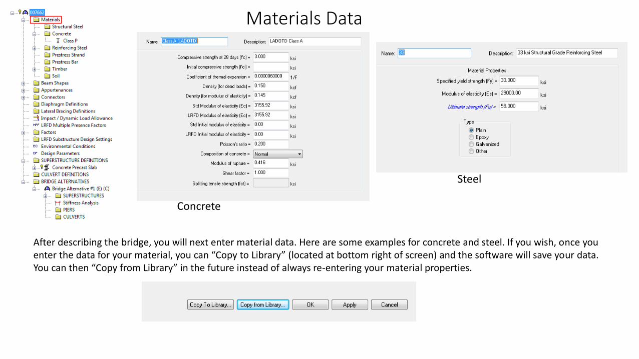
After describing the bridge, you will next enter material data. Here are some examples for concrete and steel. If you wish, once you enter the data for your material, you can “Copy to Library” (located at bottom right of screen) and the software will save your data. You can then “Copy from Library” in the future instead of always re-entering your material properties.
Concrete
Steel

Beam Shapes
We do not define any beam shapes for the COPCSS bridge type. We will enter the slab panels later under the “Superstructure Definitions” section.
Appurtenances
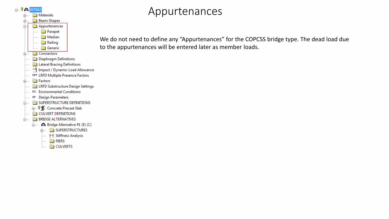
We do not need to define any “Appurtenances” for the COPCSS bridge type. The dead load due to the appurtenances will be entered later as member loads.
Superstructure Definitions
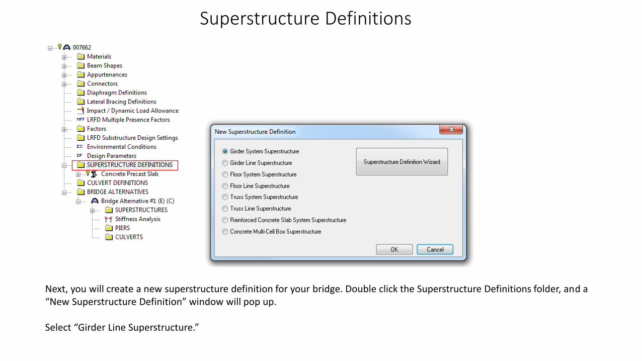
Next, you will create a new superstructure definition for your bridge. Double click the Superstructure Definitions folder, and a“New Superstructure Definition” window will pop up.
Select “Girder Line Superstructure.”

Superstructure Definitions – Definition Tab
Fill out the necessary information in the fields. Describe the bridge spans. The deck type is Concrete, and the Member Alt. Types should be R/C.
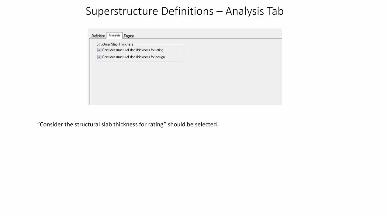
Superstructure Definitions – Analysis Tab
“Consider the structural slab thickness for rating” should be selected.

Superstructure Definitions – Engine Tab
It is not necessary to make a selection here, BrR will use the default analysis engine.
Bridge Alternatives
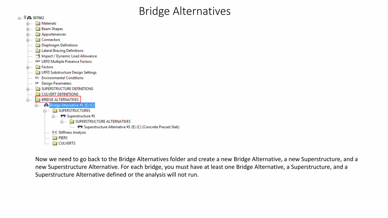
Now we need to go back to the Bridge Alternatives folder and create a new Bridge Alternative, a new Superstructure, and a new Superstructure Alternative. For each bridge, you must have at least one Bridge Alternative, a Superstructure, and a Superstructure Alternative defined or the analysis will not run.
Bridge Alternatives
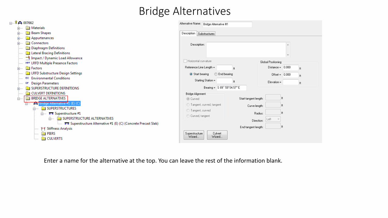
Enter a name for the alternative at the top. You can leave the rest of the information blank.

Bridge Alternatives -Superstructures
Enter a name for the superstructure at the top. You can leave the rest of the information blank.

Bridge Alternatives – Superstructure Alternatives
Enter a name for the superstructure alternative at the top. Select the Superstructure Definition from the drop down menu at the bottom, for a COSLAB bridge you will usually only have one type of superstructure definition.
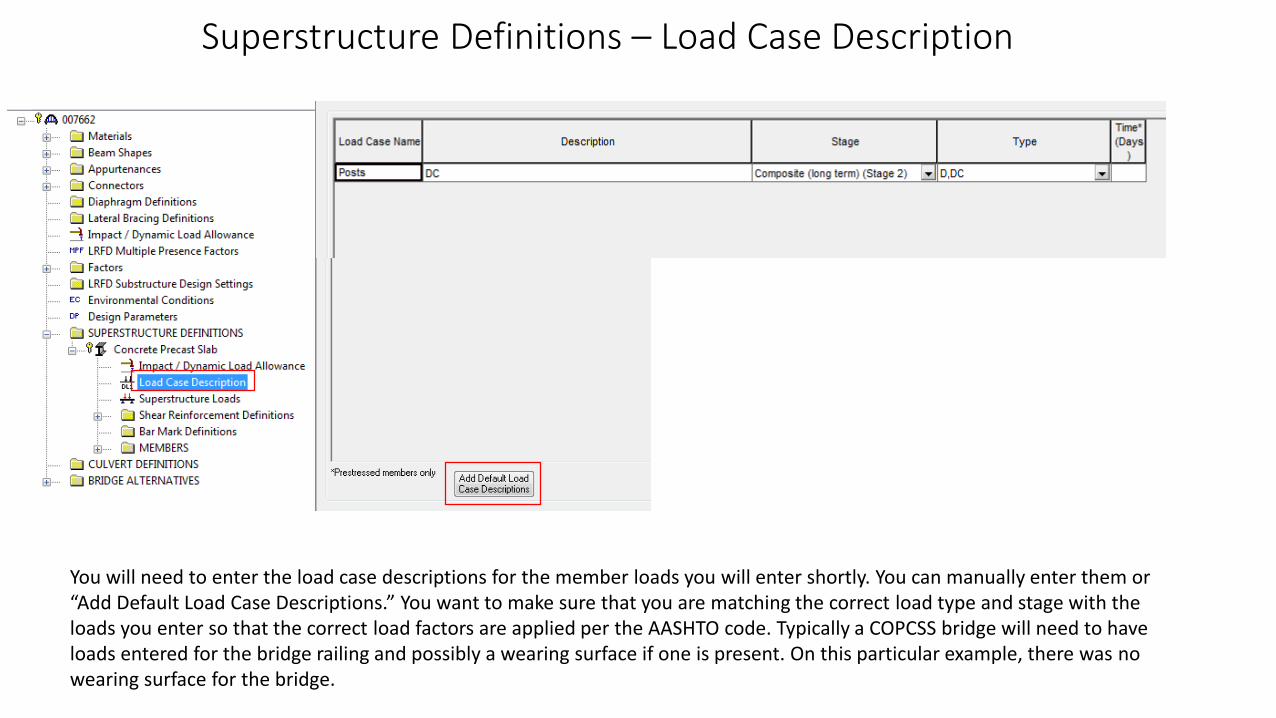
Superstructure Definitions – Load Case Description
You will need to enter the load case descriptions for the member loads you will enter shortly. You can manually enter them or“Add Default Load Case Descriptions.” You want to make sure that you are matching the correct load type and stage with the loads you enter so that the correct load factors are applied per the AASHTO code. Typically a COPCSS bridge will need to haveloads entered for the bridge railing and possibly a wearing surface if one is present. On this particular example, there was no wearing surface for the bridge.
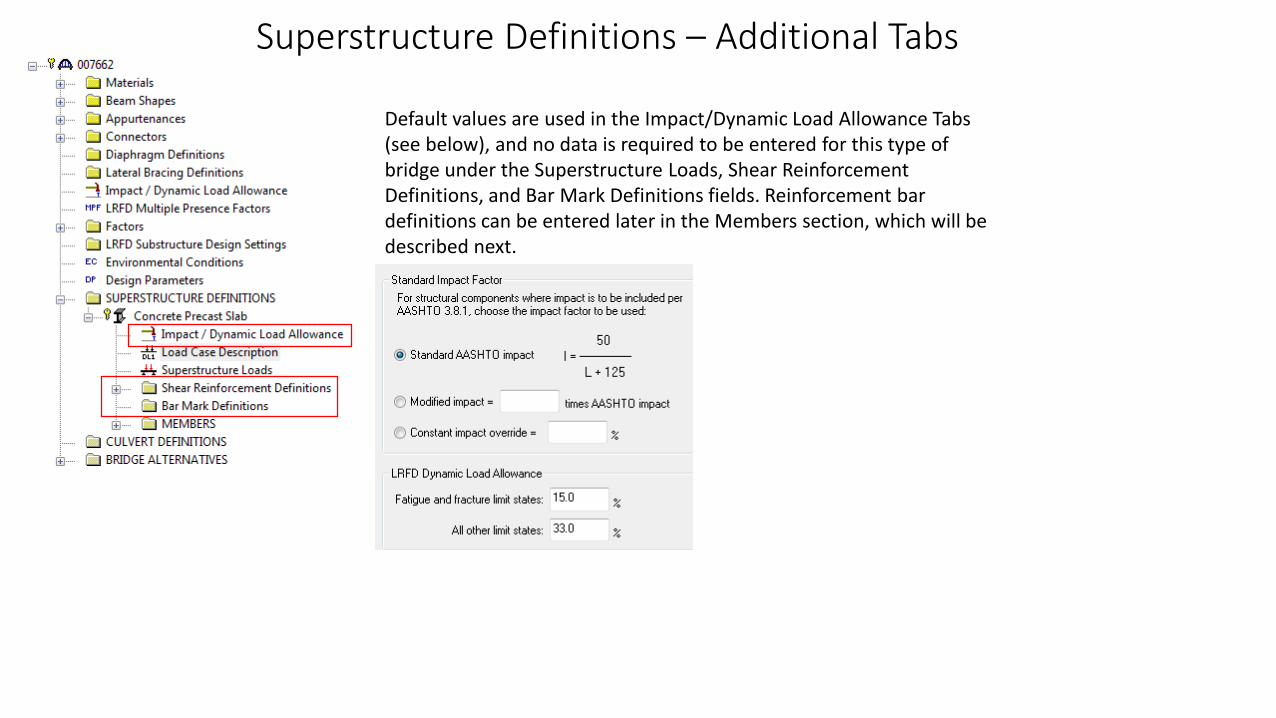
Superstructure Definitions – Additional Tabs
Default values are used in the Impact/Dynamic Load Allowance Tabs (see below), and no data is required to be entered for this type of bridge under the Superstructure Loads, Shear Reinforcement Definitions, and Bar Mark Definitions fields. Reinforcement bar definitions can be entered later in the Members section, which will be described next.
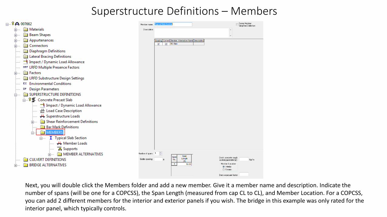
Superstructure Definitions – Members
Next, you will double click the Members folder and add a new member. Give it a member name and description. Indicate the number of spans (will be one for a COPCSS), the Span Length (measured from cap CL to CL), and Member Location. For a COPCSS, you can add 2 different members for the interior and exterior panels if you wish. The bridge in this example was only rated for the interior panel, which typically controls.
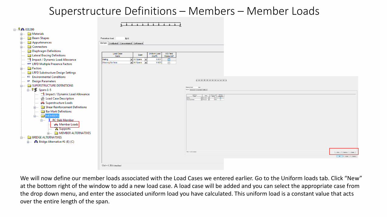
Superstructure Definitions – Members – Member Loads
We will now define our member loads associated with the Load Cases we entered earlier. Go to the Uniform loads tab. Click “New” at the bottom right of the window to add a new load case. A load case will be added and you can select the appropriate case fromthe drop down menu, and enter the associated uniform load you have calculated. This uniform load is a constant value that acts over the entire length of the span.

Notes on Railing and Wearing Surface Loads
• To calculate the load on the member from the railing and curb, calculate the weight of 2 railings + curbs for the 2 sides of the bridge, and divide by the bridge width to get the Uniform Load of the railing+curb.
• To calculate the load on the member from the wearing surface, multiply the thickness of the wearing surface by the unit weight of the wearing surface (typically asphalt) to obtain the Uniform Load
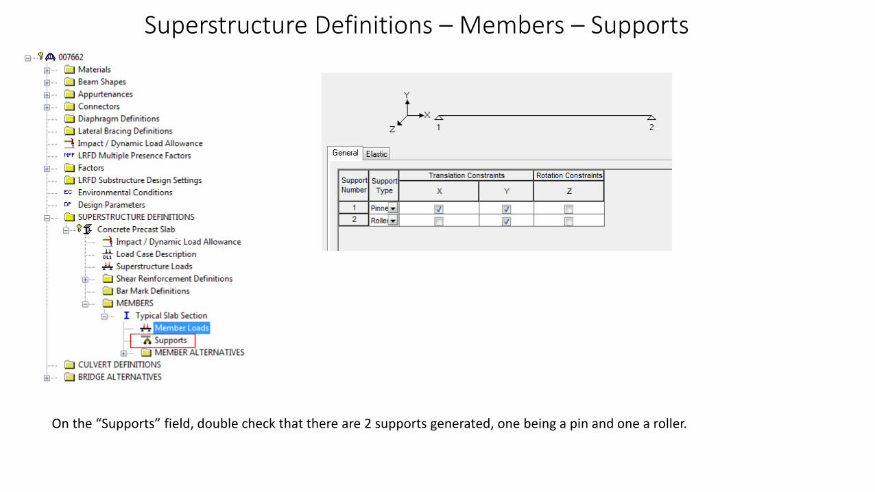
Superstructure Definitions – Members – Supports
On the “Supports” field, double check that there are 2 supports generated, one being a pin and one a roller.
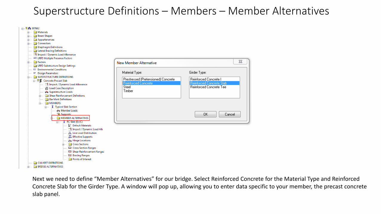
Superstructure Definitions – Members – Member Alternatives
Next we need to define “Member Alternatives” for our bridge. Select Reinforced Concrete for the Material Type and Reinforced Concrete Slab for the Girder Type. A window will pop up, allowing you to enter data specific to your member, the precast concrete slab panel.
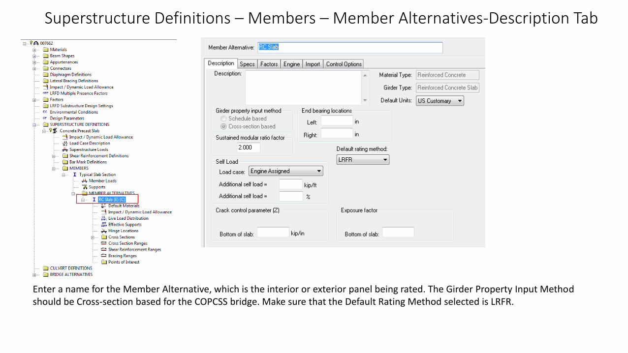
Superstructure Definitions – Members – Member Alternatives-Description Tab
Enter a name for the Member Alternative, which is the interior or exterior panel being rated. The Girder Property Input Method should be Cross-section based for the COPCSS bridge. Make sure that the Default Rating Method selected is LRFR.
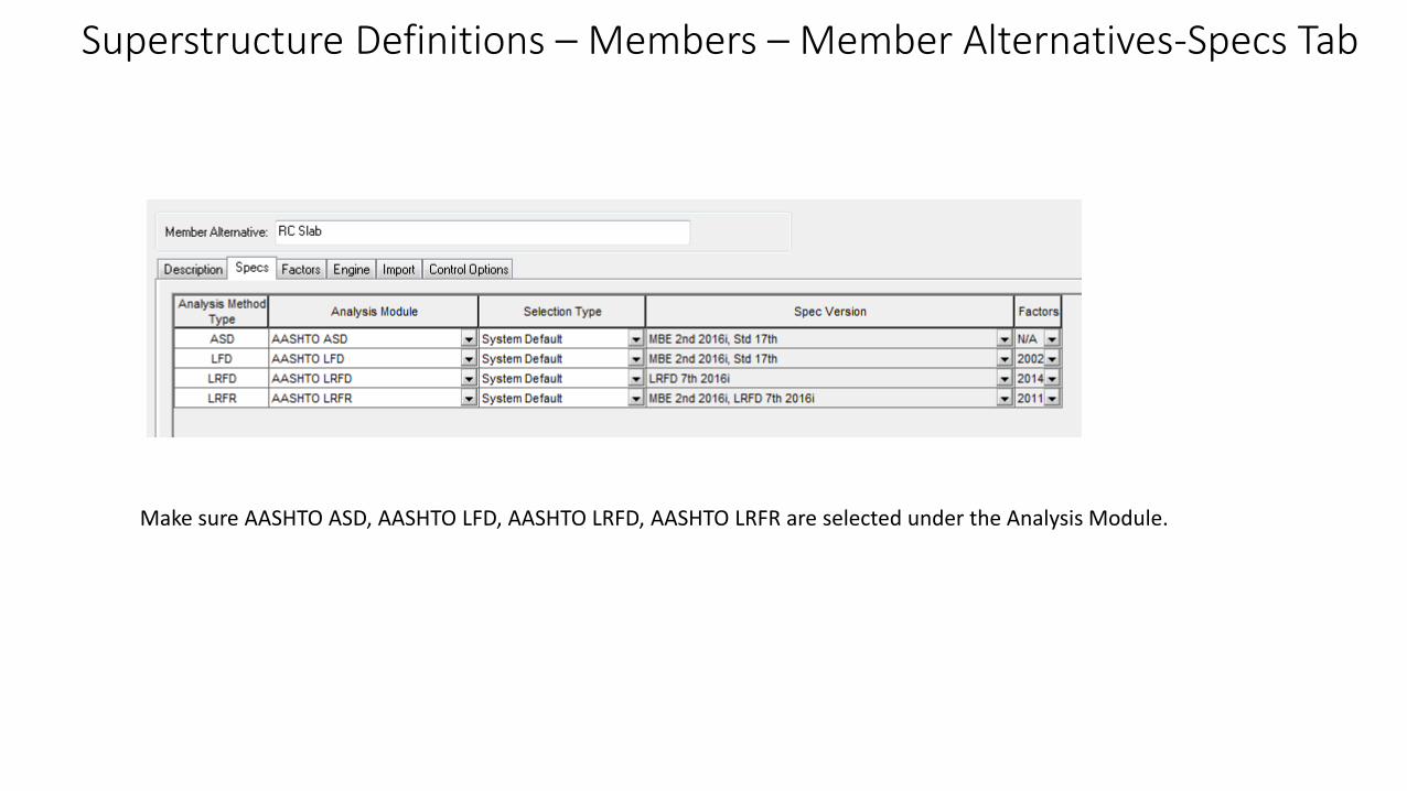
Superstructure Definitions – Members – Member Alternatives-Specs Tab
Make sure AASHTO ASD, AASHTO LFD, AASHTO LRFD, AASHTO LRFR are selected under the Analysis Module.

Superstructure Definitions – Members – Member Alternatives-Factors Tab
On this tab, you will select the condition of the bridge according the AASHTO Manual for Bridge Evaluation, Good or Satisfactory, Fair, or Poor. The system factor should be All Other Girder/Slab Bridges.
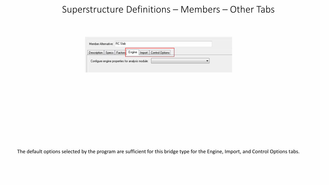
Superstructure Definitions – Members – Other Tabs
The default options selected by the program are sufficient for this bridge type for the Engine, Import, and Control Options tabs.
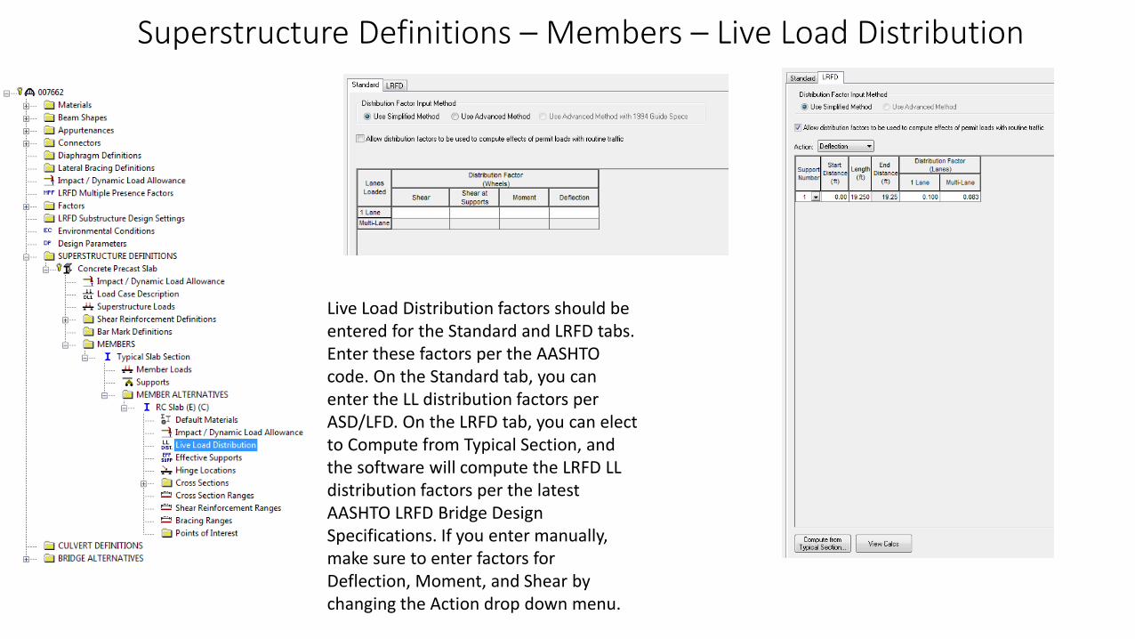
Superstructure Definitions – Members – Live Load Distribution
Live Load Distribution factors should be entered for the Standard and LRFD tabs. Enter these factors per the AASHTO code. On the Standard tab, you can enter the LL distribution factors per ASD/LFD. On the LRFD tab, you can elect to Compute from Typical Section, and the software will compute the LRFD LL distribution factors per the latest AASHTO LRFD Bridge Design Specifications. If you enter manually, make sure to enter factors for Deflection, Moment, and Shear by changing the Action drop down menu.

Superstructure Definitions – Members – Cross Sections Folder-Dimensions Tab
Now it is time to define our slab panel cross section. Double click the cross section folder. In the window that pops up, enter a name for the cross section. Enter the slab cross sectional dimensions-since we are using a panel, enter the panel width in inches. Enter the slab thickness, and on the right, select the concrete material (the material you entered earlier should be available in this drop down menu).
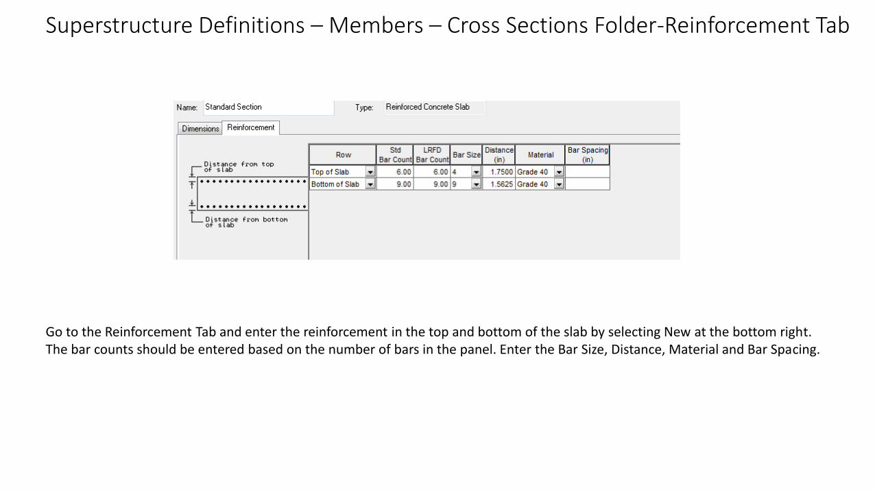
Superstructure Definitions – Members – Cross Sections Folder-Reinforcement Tab
Go to the Reinforcement Tab and enter the reinforcement in the top and bottom of the slab by selecting New at the bottom right. The bar counts should be entered based on the number of bars in the panel. Enter the Bar Size, Distance, Material and Bar Spacing.
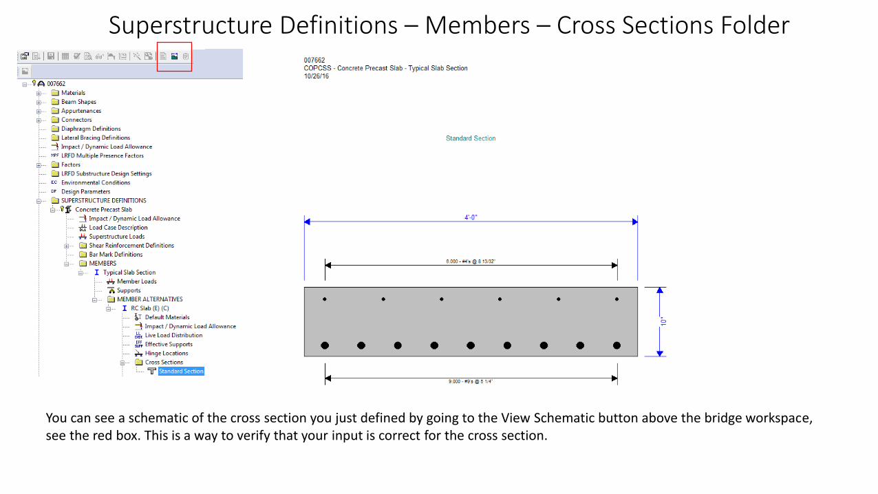
Superstructure Definitions – Members – Cross Sections Folder
You can see a schematic of the cross section you just defined by going to the View Schematic button above the bridge workspace, see the red box. This is a way to verify that your input is correct for the cross section.

Superstructure Definitions – Members – Cross Sections Folder-Cross Section Ranges
Now we will define the Cross Section Ranges for the bridge. This must be done in order for the analysis to run. In this case, the length of the cross section is the length of the span you defined earlier. The Start and End Sections are the Cross Section that was defined.

Superstructure Definitions – Members – Cross Sections Folder-Other Fields
The Effective Supports, Hinge Locations, Shear Reinforcement Ranges, and Bracing Ranges are not applicable to this member so we will not enter data into these fields. We also do not need to define any Points of Interest.
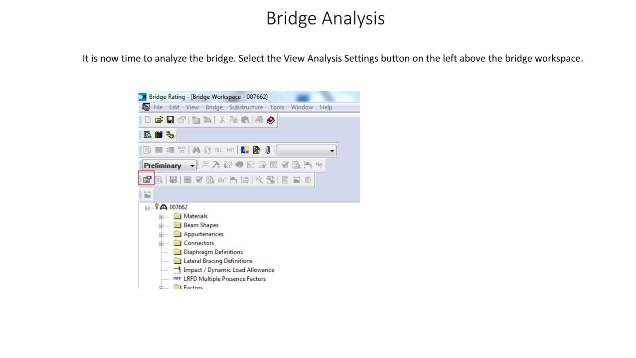
Bridge Analysis
It is now time to analyze the bridge. Select the View Analysis Settings button on the left above the bridge workspace.
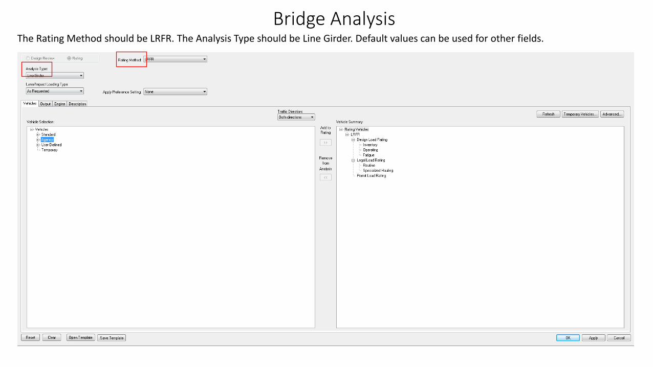
Bridge AnalysisThe Rating Method should be LRFR. The Analysis Type should be Line Girder. Default values can be used for other fields.
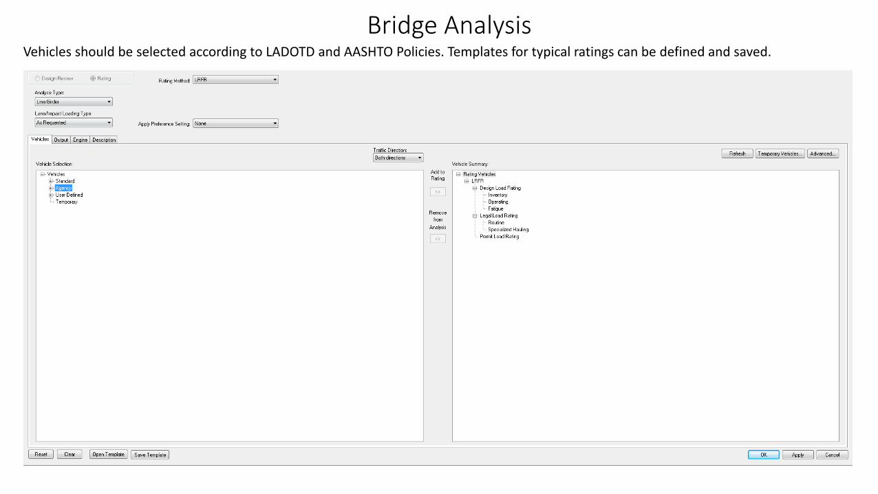
Bridge AnalysisVehicles should be selected according to LADOTD and AASHTO Policies. Templates for typical ratings can be defined and saved.

Bridge Analysis
After adding the appropriate vehicles, you can exit the Analysis Settings window and run the analysis. First, select the Member for which you want to run the analysis. In this case, we only have one member, the RC Slab Member. After selecting the member, go to the Analyze tab and click to run the analysis.

Bridge Analysis - Results
When the analysis has completed, you can view the results by going to the member alternative. Select this member alternative, and several buttons that were inactive become active. Select the button that looks like a spreadsheet.
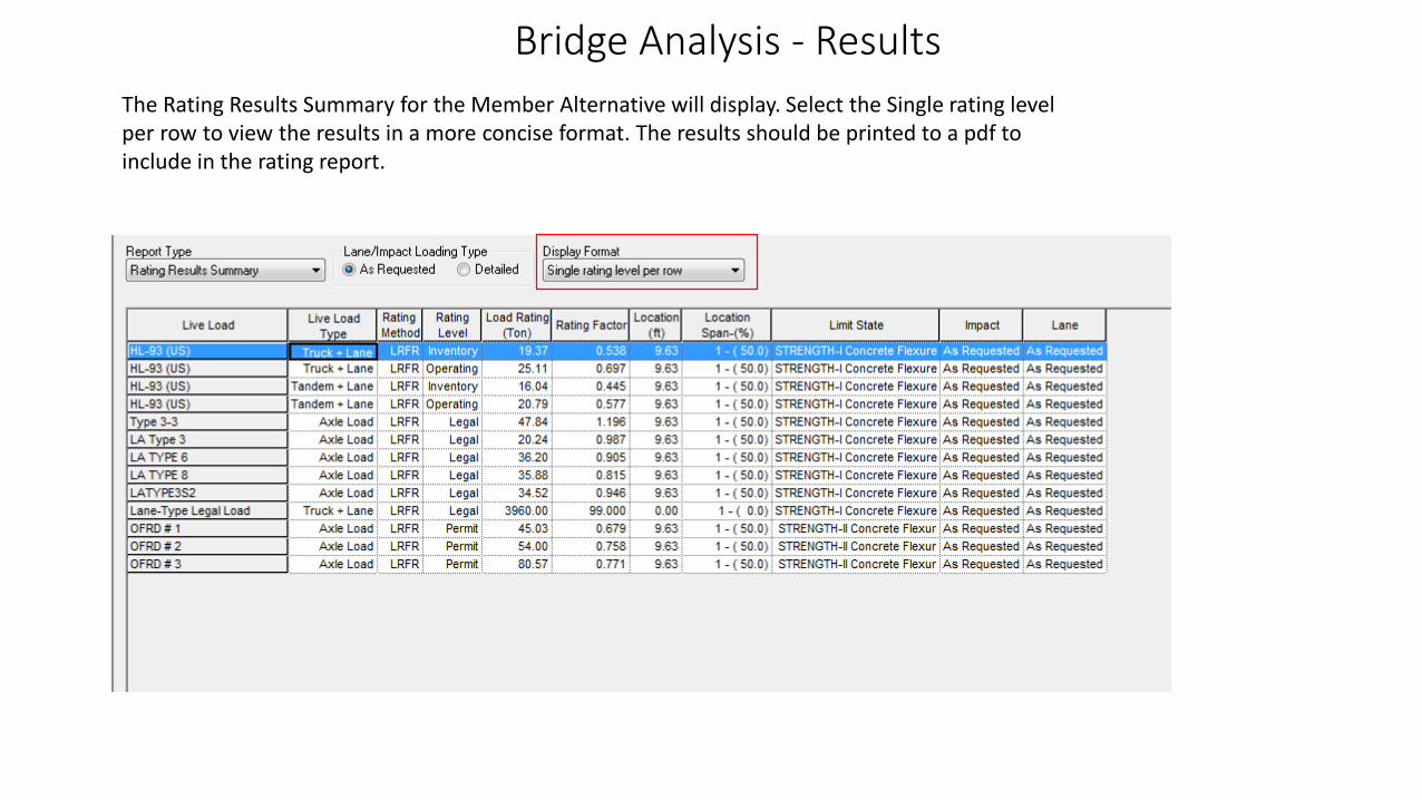
Bridge Analysis - Results
The Rating Results Summary for the Member Alternative will display. Select the Single rating level per row to view the results in a more concise format. The results should be printed to a pdf to include in the rating report.
Bridge Analysis - Results
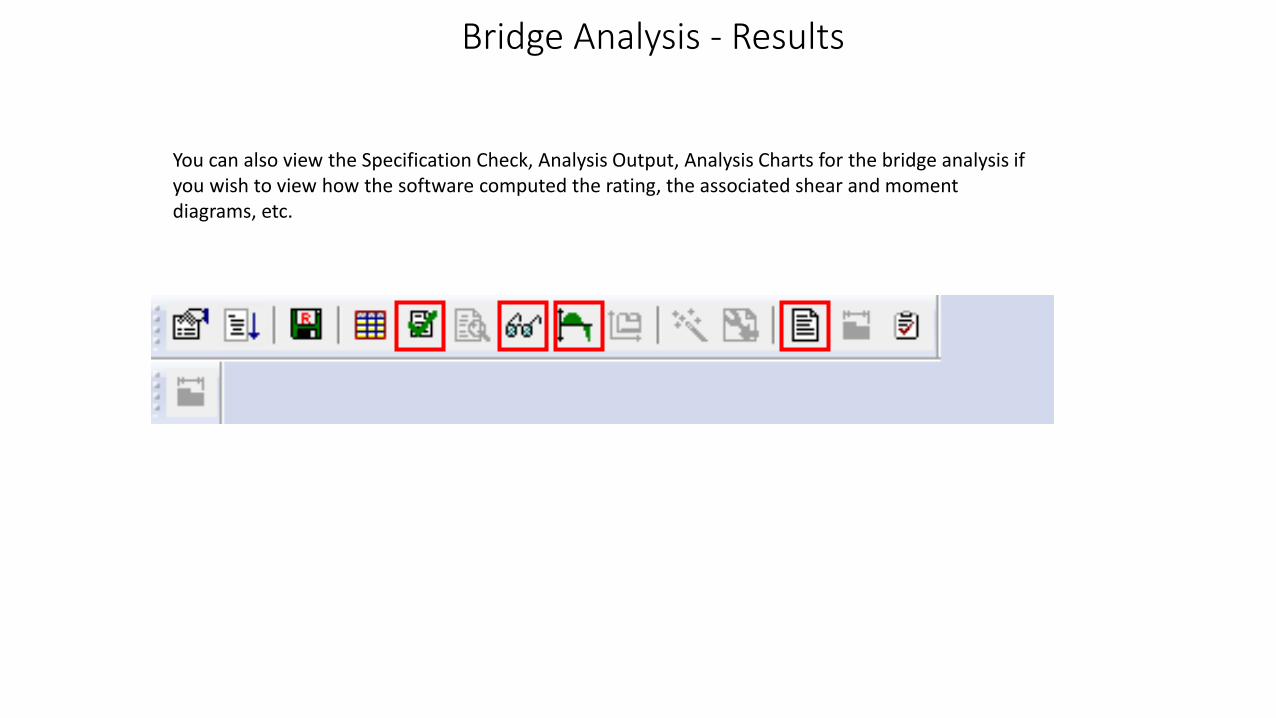
You can also view the Specification Check, Analysis Output, Analysis Charts for the bridge analysis if you wish to view how the software computed the rating, the associated shear and moment diagrams, etc.