brush contact drop in d. c. machines
TRANSCRIPT

BRUSH CONTACT DROP IN D. C. MACHINES. By M. Kesava Rao.
INTRODUCTION.
The characteristics of the voltage drop at the brush contacts in continuous current machines under running conditions have been studied by a number of investigators in view of their great importance as regards sparkless commutation. The main difficulty in an investi- gation of this nature is to reproduce results under apparently identical conditions, and this difficulty is responsible for the wide disagreement between the results obtained by different experimenters. The object of the present investigation is to determine the influence of the rotation of the commutator on the brush contact drop.
Baily and Cleghorne (J.I .1-LE., 1906, 38, 162) experimenting with slip-rings did not observe any appreciable difference between the values obtained when the slip-rings were stationary and when running at moderate speeds. Arnold (Die Gleichslronzmaschine, 1910, 1, 348) obtained similar results with slip-rings. Edgecomb and Dick (Proc. A.I.E.E., 1913, 32, 451-461) experimented with a short-circuited commutator and observed that the contact drop increased with peripheral speed. Gratzmuller (La. Lum. Elec., -1913, 21, 324) worked on a commutator with the brushes mounted side by side and in the same axial line, the current passing longitudinally along the segment from one brush to the other. He observed a large increase in the contact drop, amounting to about 100 per cent., as soon as rotation commenced, but the value remained unaltered with speed. An objection to this method pointed out by Hay, Bhatt and Parikh (J././.Sc., 1914-18, 1, 71) is that the current density over the brush contact area would not be uniform owing to the crowding of the stream lines towards the edges of the brushes facing each other. This objection does not, however, appear to be valid, since the distribution of current over the surface of the brush is mainly determined by the contact resistance, the resistance of the path of current through the commutator segment being comparatively negligible.
Recently, Taylor (J. I. E. E., 1930, 68, 1356-1362), experi- menting with a slip-ring, studied the variation of the contact drop with speed, brush-pressure and current at peripheral speeds higher than those employed by previous investigators. The investigation was also extended to very low current densities and it was observed that when the slip-ring was stationary the contact drop was nearly
F
4.

92
proportional to the current ; but when it was running, there tvas a limiting value of the voltage below which no appreciable current could flow. This can be explained by assuming a sudden increase in the voltage drop following the commencement of rotation. Curves connecting contact drop and brush-pressure indicate that the drop decreases with increase of brush-pressure. Curves connecting contact drop with speed for various brush-pressures show that the drop increases slowly up to a certain speed but the rate of increase suddenly rises at that speed. He suggested that the sudden increase at high speeds was due to intermittent contact and the formation of an air film between the brush and the slip-ring.
EXPERIMENTAL.
All experiments with slip-rings suffer from the defect that they do not represent the working conditions in a d-c machine. Conse- quently, a commutator machine was used in the present investigation.
For the purposes of the experiments, a d-c motor-generator set comprising two similar 5 kW, 220 V, 750 r.p.m., wave-wound rotary converters was used. One of these was used as the machine under test while the other one was used as the driving motor. The armature of each machine had a search coil connected to a pair of slip-rings, so that it was possible to investigate the flux distribution in the air gap under different conditions. The brush-gear was mounted close to the end shield so that there was little vibration in the brushes. There were four brush arms each carrying a brush of 3/8 sq. inch cross section. The full load current density in the brushes was therefore 28 amps./sq. inch. The set was quite new and the commu- tator had therefore a very smooth surface and the mica was well undercut.
The following 'method of testing was adopted. Before each set of tests the commutator was carefully cleaned, and the set was run without any current for a sufficiently long time to ensure a proper bedding of the brushes. It was then stopped and a known current was passed through the armature. The total voltage drop between the positive and negative brushes, and the drop in the wind- ings were measured. The difference between the two readings is the sum of the brush resistance and the brush contact drops. As the former is negligible, the difference was taken as the brush contact drop under stationary conditions.
under running conditions case the total drop between
to the resistance drop, e.m.t. s inaucea in tne armature. It was therefore necessary
The measurement of contact drop required greater precautions, for in this the brushes would include, in addition _ t , • , , • .•
any to
Mi•
S 1010 volts D.C. supply Low v
D.C. S Machine Liman
lest
93
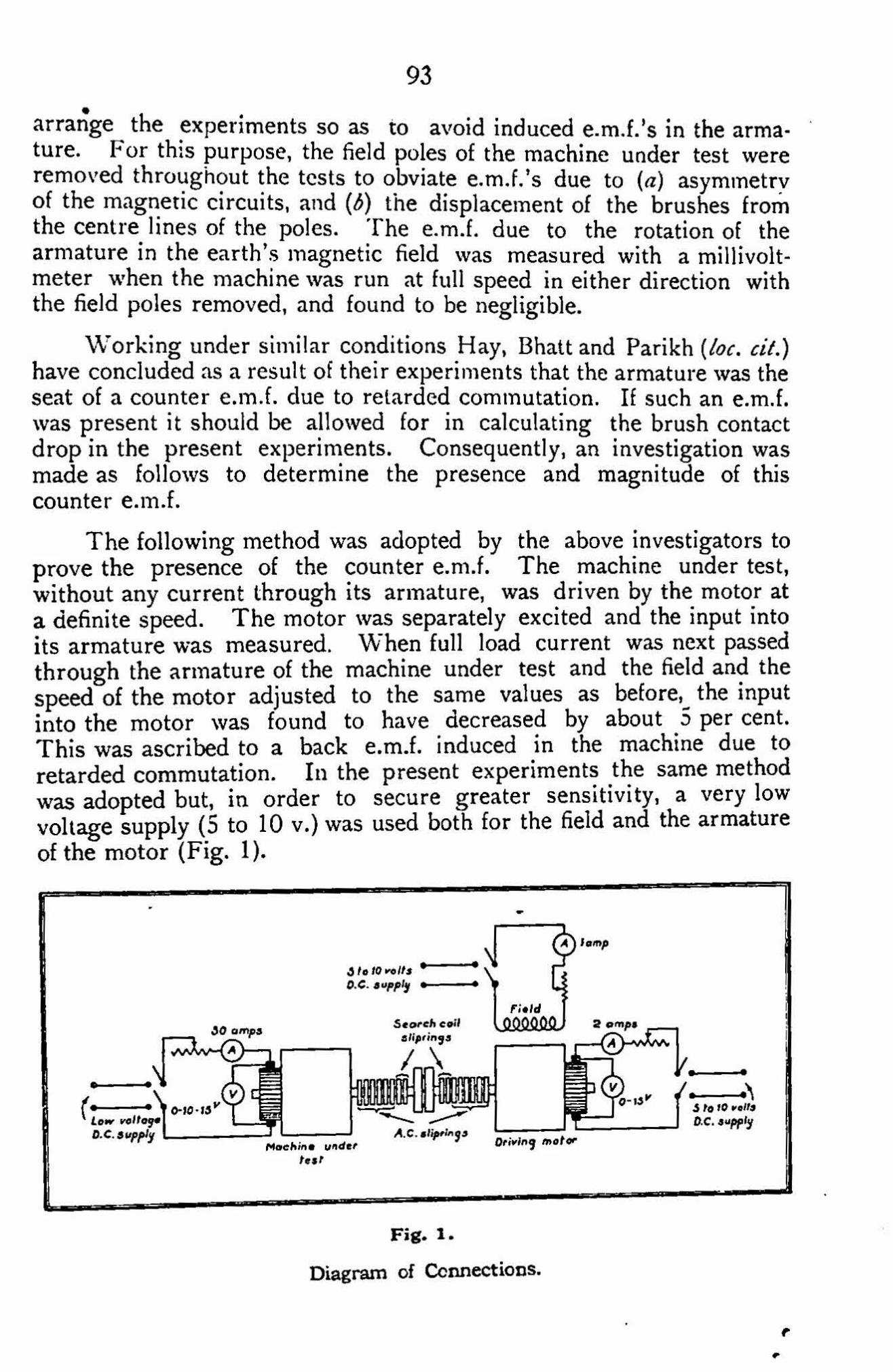
arrange the experiments so as to avoid induced e.m.f.'s in the arma- ture. For this purpose, the field poles of the machine under test were removed throughout the tests to obviate e.m.f.'s due to (a) asymmetry of the magnetic circuits, and (6) the displacement of the brushes from the centre lines of the poles. The e.m.f. due to the rotation of the armature in the earth's magnetic field was measured with a millivolt- meter when the machine was run at full speed in either direction with the field poles removed, and found to be negligible.
Working under similar conditions Hay, Bhatt and Parikh (boc. cit.) have concluded as a result of their experiments that the armature was the seat of a counter e.m.f. due to retarded commutation. If such an e.m.f. was present it should be allowed for in calculating the brush contact drop in the present experiments. Consequently, an investigation was made as follows to determine the presence and magnitude of this counter e.m.f.
The following method was adopted by the above investigators to prove the presence of the counter e.m.f. The machine under test, without any current through its armature, was driven by the motor at a definite speed. The motor was separately excited and the input into its armature was measured. When full load current was next passed through the armature of the machine under test and the field and the speed of the motor adjusted to the same values as before, the input into the motor was found to have decreased by about 5 per cent. This was ascribed to a back e.m.f. induced in the machine due to retarded commutation. In the present experiments the same method was adopted but, in order to secure greater sensitivity, a very low voltage supply (5 to 10 v.) was used both for the field and the armature of the motor (Fig. I).
Fig. 1.
Diagram of Connections.
9.

94
The input into the motor armature balanced its no-load fosses (friction, windage and iron losses) and armature copper loss. 'The reduction of input due to the counter e.m.f. in the armature under test was a small fraction of the input. Consequently, by using a low field voltage the iron losses were reduced and greater sensitivity obtained. By using a low armature voltage, the armature current was correspondingly increased and could be measured with a high degree of accuracy. With this arrangement, it was possible to detect a change in the input of the order of 1 part in 500, but no change was observed even with speeds up to 900 r.p.m. and currents up to twice the full load current of the machine.
In order to verify the result, the following retardation method was adopted (Fig. 2). The set was run up to a definite speed without any
•
field D.P.Switch
40 amps Search coil
0 sliprings
Low voltage 0-C- 3 upply FL AC.stiprings
Machine under test
Driving motor Star ter
Sett Drive
Magneto generator
= To ondo graph
Fig. 2.
Diagram of Connections for Retardation Test.
current through the armature under supply of the motor was next switched observed. The experiment was then through the armature under test.
test. The armature and field off and the rate of retardation repeated with a known current
A counter e.m.f. in the armature under test would give rise to a motoring torque, and consequently the retardation of the set would be reduced and it would take longer to come to rest. The retardation in each case was recorded by means of an ondograph. A magneto- generator was belted to the set so that the variation of its e.m.f. was a measure of the variation of the speed of the set. The e.m.f. was applied to the galvanometer of the ondograph of which the drum was driven at a constant speed by supplying its synchronous motor from a source of constant frequency. On superposition, the two retardation curves

95 6 •
obtained with and without current through the armature under test coincided exactly, indicating an absence of an induced e.m.f. in the armature. This confirmed the result obtained previously by the other method. The arrangement was sensitive enough to record changes in the torque of the order observed by the above investigators.
It is, however, possible that the counter e.m.f. in the armature was just enough to balance the additional losses in the armature core due to its rotation in its own stationary field. Another experiment was therefore carried out to determine the order of this loss. The wave shape of the flux due to the armature current was traced by means of an oscillograph connected to the search coil, the oscillograph motor being supplied from the motor slip-rings. The nature of the oscillogram is shown on Fig. 3 and shows a number of ripples which increase in amplitude as the crest of the wave is approached. The
Fig. 3.
Flux Wave due to Armature Current with Field Poles removed. Armature Current 40 Amp. Speed 900 r.p.m.
nature of the ripples indicates that they are due to voltages induced in the search coil by mutual induction with coils undergoing short- circuit, the mutual induction being greatest when the search coil comes into line with the brushes, and therefore with the coils under- going short-circuit. The induced voltage can therefore be resolved into two components : (a) the dotted curve representing the effect of rotation in the armature flux, and (6) the ripples superposed on it, due to mutual induction.
The dotted curve is a measure of the maximum induction due to armature current. The next point was therefore to determine whether

96
• • the hysteresis and eddy current losses due to this value of induction could absorb any appreciable counter e.m.f. For this purpose, the field poles were replaced and the set was run again at the same speed as before without any current through the field or armature of the machine under test, and the motor input was noted. The field of the machine under test was now excited so as to produce the same value of maximum induction as that produced by the armature current in the previous test, this condition being determined by the oscillograph. The motor input was again noted. The difference between the two values of the motor input gives the iron losses corresponding to the value of induction. It was found that even for armature current equal to twice the full load current and at the maximum permissible speed (900 r.p.m.), the loss was of the order of 5 watts and the corres- ponding back e.m.f. negligible as compared with the contact drop.
All this proves that there is no appreciable counter e.m.f. in the armature and, neglecting the brush resistance drop, the difference between the total drop and the armature drop can be taken as being equal to the contact drop.
However, the contact drop is very largely affected by the nature of the surface of the commutator as can be seen from the following experiment. The commutator was polished and the contact drop measured by passing a known current when the machine was stationary. The commutator was next blackened by passing a large current through it and running the machine for some time. The machine was stopped and the contact-drop measured with the same current as before. The drop was found to be considerably reduced. The commutator was again polished and on measuring the drop again with the same current, it was found that it had increased to more or less the same value.
Consequently, it is essential that in tests for determining the increase of contact-drop due to rotation, involving alternate readings at stand-still and under running conditions, the nature of the commutator surface should remain unchanged as far as possible between each pair of readings. In order to approximate to this condition as far as possible the following procedure was adopted: (1) A definite value of current was passed through the armature under test at stand still and the voltage drop measured. (2) The current being maintained at the same value, the armature was driven at the required speed and the drop
. measured again. (3) The current being still maintained at the same value, the armature was again brought to rest and the drop measured once more. All the three readings were taken as quickly as possible in order to minimise the change in the nature of commutator surface. The mean of readings 1 and 3 was taken as the drop under stationary condition, and was deducted from the drop obtained in reading 2 in

97 •
order to obtain the increase of drop due to rotation. A set of read- ings corresponding to a definite speed and increasing values of current was first taken, and similar sets were then obtained at different speeds. At the beginning of each set the commutator was cleaned.
Fig. 4 represents the variation in the value of " the stationary drop ". The stationary drop corresponding to a definite speed repre- sented by each of the curves in the figure is the mean value of readings
Ma i Ct. 0
45 b C 0 ._ a 4-
tf)
lid 100 R . P. 1 1.
2 0 0 R. P. ri, Irrr rooral . 300 ft P. M.
rr
a 4 00 R .P.m.
All.s 550 R A
00110taill ire: . . . 900 R . 01;0111111111
re- 13, xi di i 0011111110 0111111111111A_ 700 R. P PI .
witr -sea 41,100.0.1
a
eraPill or __.
Ar mature c ur r e n t avrasp—sia
0
5 10 15 230
30 35 40
Fig. 4.
Effect of Commutator Surface on Contact Drop.
1 and 3 obtained for that speed, plotted against the varying current. It will be seen that the stationary drop at zero speed is represented by the highest curve while the stationary drops at other speeds become smaller as the speed increases. This is due to the greater blackening, and consequently lower drop, at increasing speeds. The reduction in the voltage drop with increase of speed is very great at first but becomes smaller until it seems to become very small at about 750 r.p.m. These curves bring out the extreme importance of obtaining the change in contact drop from a pair of readings obtained under similar conditions of commutator surface.
Fig. 5 represents the increase of voltage drop due to speed. At each value of speed, the drop initially increases in direct proportion to the current, but the rate of increase becomes smaller until it finally tends to reach a constant value. This constant value is, however, not reached with the maximum current used in the experiment. It was not possible to push the current up to higher values due to sparking.
2.0
1.3
1.0
0 .5

98
900
750
.
a 43
u
It
550
t fr.--3.--
•
a C o U
0
rr 4 00•
In 0 v I- (.) C ...
300
2 00
..r
ir A rmatur e A
es— 10 0
curren 0 5 10 15 20 25 430 35 4 0
Fia. 5.
Increase of Brush Contact Drop due to Speed.
For a definite value of the c increases with speed. Fig. 6, effect of increasing speeds with that, with constant current, the proportion to the speed.
ur rent, the increase in contact drop derived from Fig. 5, represents the definite values of current and indicates increase in drop increases in direct
It is believed that these results represent more correctly the effect of speed on the brush contact drop than those obtained by previous investigators. Most of them have worked with slip-rings instead of commutator, while those who have worked with the commutator do not seem to have realised the importance of the error due to the change in the surface of the commutator during each set of their experiments.
. Observations were also made to ascertain if the "stationary con- tact drop at zero speed" could be reproduced from day-to-day and the results shown on Fig. 7 indicate that it could be reproduced with reasonable accuracy on different days provided the commutator was well cleaned at the beginning of each set of readings.
8
7
6
5
4
a
2

99
off'
0
i
o
co 0 °
13-
co v) - ti 4) IL. 0
_ x
rn Ps
Al01 01101r 40.00000
a rn P
..,A#I Speed R.P.M. ..--ale--
0 100 200 300 400 500 600 700 800 300 1000
Fig. 6.
Increase of Brush Contact Drop due to Speed.
i 4.. _____________ 4. 0)
'0 C
1.3. 4
0
X
- •
- *0 4.. 0
Q. 0
45 . •
• Values obtained on 3-10-33
0 / / / 7 14- IX -30
X p f 7 t 13- 12-53
1./ 0
A- C 0 U i
Armature current. 2i.---.11- .
o 5 10 15 20 25 30 35 4 0 45
Fig. 7.
Contact Drop at Stand Still.
3
4
a
3'0
25
2. 0
1 - 0
05
•

100
CONCLUSIONS.
The investigation brings out the following results :--
(1) The contact drop between the commutator and the brush is capable of being reproduced fairly satisfactorily on different days, if care is taken to clean the commutator before each set of observations.
(2) The effect of blackening of the commutator due to the passage of current, when the commutator is running, is very large and may produce considerable errors in the observations, unless duly allowed for.
(3) No counter e.m.f. due to retarded commutation was observed.
drop increases with increasing speed. For the increase is initially in direct proportion
to a constant value at very high currents. With constant current, the increase is in direct proportion to the speed upto the maximum speeds experimented with.
ACKNOWLEDGMENT.
The author is highly indebted to Prof. F. N. Mowdawalla for his very valuable guidance throughout the investigation.
Department of Electrical Technology, Indian Institute of Science,
Bangalore. [Accepted, 25-6-19344
'4) The brush contact the same value of speed, to the current but tends
1138-34.—Printed at 'Die Bangalore Press. Mysore Road. Bangalore Cny, by T. Subramania itiyar, Superintendent.