bryan isd davila addendum no 02 equipment, and the lighting system is to be provided under section...
TRANSCRIPT

Stantec Architecture Inc. 20 East Greenway Plaza, Suite 200, Houston TX 77046-2012
Project Name: Davila Middle School Addition Date: September 15, 2015 Addendum No. Two (02) Page 1 of 4
ADDENDUM Addendum Number Two (02) TO PLANS AND SPECIFICATIONS FOR ARTHUR L. DAVILA MIDDLE SCHOOL ADDITION STANTEC Project No: 214000309 STANTEC ARCHITECTURE INC. 20 E. GREEWAY PLAZA, SUITE 200 HOUSTON, TEXAS 77046 SEPTEMBER 15, 2015 NOTE: If you have questions about this Addendum, please contact Jose Garcia, Senior Project Manager. This Addendum is generally seperated into sections for convenience; however, all contractors, subcontractors, material suppliers and other involved parties shall be responsible for reading the entire Addendum. Failure to list an item(s) in all affected sections of this Addendum does not relieve any party affected from performing per instructions, provided the information is set forth one time anywhere in the Addendum. This document shall become attached to and part of the Construction Documents for the aforementioned project. Miscellaneous Items
1. D. Armstrong is not an approved LVT Flooring material supplier as previously approved under Addendum #1, dated September 4, 2015.
2. CLARIFICATION: AWP-4 is not used in this project. 3. ADDITION: Ensemble A151 to receive AWP-3 on all sides. 4. DELETE, drawing G111 – Phasing Drawing from the Drawing Index.
Contractor Questions
1. Metal Decking: Does the proposed metal decking meet your specifications? Response: Davila MS – Yes, 1.0 CSV22 is acceptable. 2. Fire Proofing: Plan page A005 – do the structural steel columns require fire proofing? See
details on plan page. Looks like something is around the columns. Response: No fire proofing required 3. Architectural Floor Plan Graphics: : Detail A5/A111 – what do the lines thru the wall (@
Dressing) designate? Response: Refer to “Wall to Deck Rating Legend”

Project Name: Davila Middle School Addition Date: September 15, 2015 Addendum No. Two (02) Page 2 of 4
4. Wall Types: Can you tell me the wall types (per plan page A004) that are drawn on A111, A112 & A113? Which go to the deck and which won’t go to the deck?
Response: Refer to “Wall to Deck Rating Legend” 5. Theatrical Lighting: The pipe rigging has no power. The light fixtures are powered from the
ceiling with 10 foot long pig tails. These light fixtures interface with a diming control panel s powered by elelctrical room #301. The rigging is to be provided under Section 11 61 33 – Theater Equipment, and the lighting system is to be provided under section 26 55 61 – Theatrical Lighting Equipment. The rigging grid is indicated on drawing A7/A611
6. Architectural Clarification: Plan page A112, Room E136 – what does the “C” designate? Response: Should read “S5” window type.
7. Architectural Finishes: Plan page A802 – Finish Schedule Area ‘J’ calls to match wall paint color/match existing ceramic tile pattern to 6-0 aff/ match existing flooring pattern. What area is this to match? Response: The design finishes are noted in the finish schedule and indicated on the drawings. The design intent is to match the existing which is what is indicated in the drawings and specifications.
8. Architectural Floor Finish Alternates: The three (A,B,C) manufactures indicated on the Color Schedule indicate the three prefferred manufactures. The Finish Schedule indicates the floor type only. The Proposal Form for Alternates is revised under this Addendum so that you can price each of the three (A,B &C)
9. Alternates: Plan page A011 shows the shaded areas for an Alternate. Should I assume that
is for Alternate #1? Response: Yes, but only the primary and secondary corridors in the existing facility.
10. Alternates: Plan page EL214 – General Lighting Notes – light fixtures shown shall be
included in Alternate #2. Aren’t these fixtures to be in Alternate #7? If not, what fixtures are in Alternate 7? Reponse: The note on sheet EL214 is incoorect and should read Alternate #7.
11. Alternates: Alternates 9 & 10. Is the FFE the same as the designation FF & E on plan page
A001 (abbreviations)? Reponse: Yes
12. Schedule: Can the Choir building be worked on during the school year? Say between the
hours of 8 AM and 3 PM? Response: Refer to Owners Special Requirments under section 01 80 00 as revised under this Addendum.
Approved Material Suppliers
1. Under section 07 27 26, Part 2.1 Manufacturers, add STO: Emerald Coat in Minimum 40 dry mil thickness.
2. Under section 07 27 26, Part 2.1 Manufacturers, add Prosoco R-Guard Spray Wrap Minimum 40 dry mil thickness.

Project Name: Davila Middle School Addition Date: September 15, 2015 Addendum No. Two (02) Page 3 of 4
3. Under section 07 27 26, Part 2.1 Manufacturers, add Barritech VP, Carlisle Coatings & Waterprooofing Minimum 40 dry mil thickness.
4. Under section 09 30 00, Part 2.3A & B. Manufactures, add Ardex. SPECIFICATIONS
1. ADDITION: Specification Section 07 95 00 PREMANUFACTURED EXPANSION JOINT SYSTEMS.
2. DELETION: The following specification sections are deleted from the Master Table of Contents: Section 01 45 29 – Testing Laboratory, this section is part of section 01 40 00 - Quality Requirements. Delete section 09 97 35 – Dry Erase Coating, this product is not used.
3. REVISION: SECTION 00 23 13 – Ranking Criteria for Competitive Sealed Proposal. Additional information provided with regards to the ranking criteria and total possible points.
4. DELETION: SECTION 09 97 35 – DRY-ERASE COATING. This product is not used.
5. DELETION: SECTION 10 14 00 PART 1-1.1, A: Following items are not used in the project:
2. Cast Aluminum building plaque
3. Freestanding dimensional metal letters anchored to top of aluminum entry canopy
4. Cast metal plaques
6. DELETION: SECTION 10 14 26 - POST AND PANEL SIGNS. This item is not used in the project.
7. ADDITION: Section 11 61 23 – Portable Seating Riser System.
8. REVISE: SECTION 01 23 00 – Alternates, as noted.
9. REVISE: SECTION 00 41 10 – Proposal Form (Alternates Proposal), as noted
10. REVISE: Section 01 80 00 - Special Owner Requirements, under Item 8. Site/Building Rules and Regulations, Add item # 14. There shall be no noise (disturbance to school) on State testing days on March 29 & 30, 2016 and May 9, 10, 11 & 12, 2016. Add item #15 . All interior renovation work to the existing portions of Davila MS are to be performed over the Summer Break and completed by August 15, 2016 so as to not disrupt the operations of the school.
DRAWINGS
ARCHITECTURAL
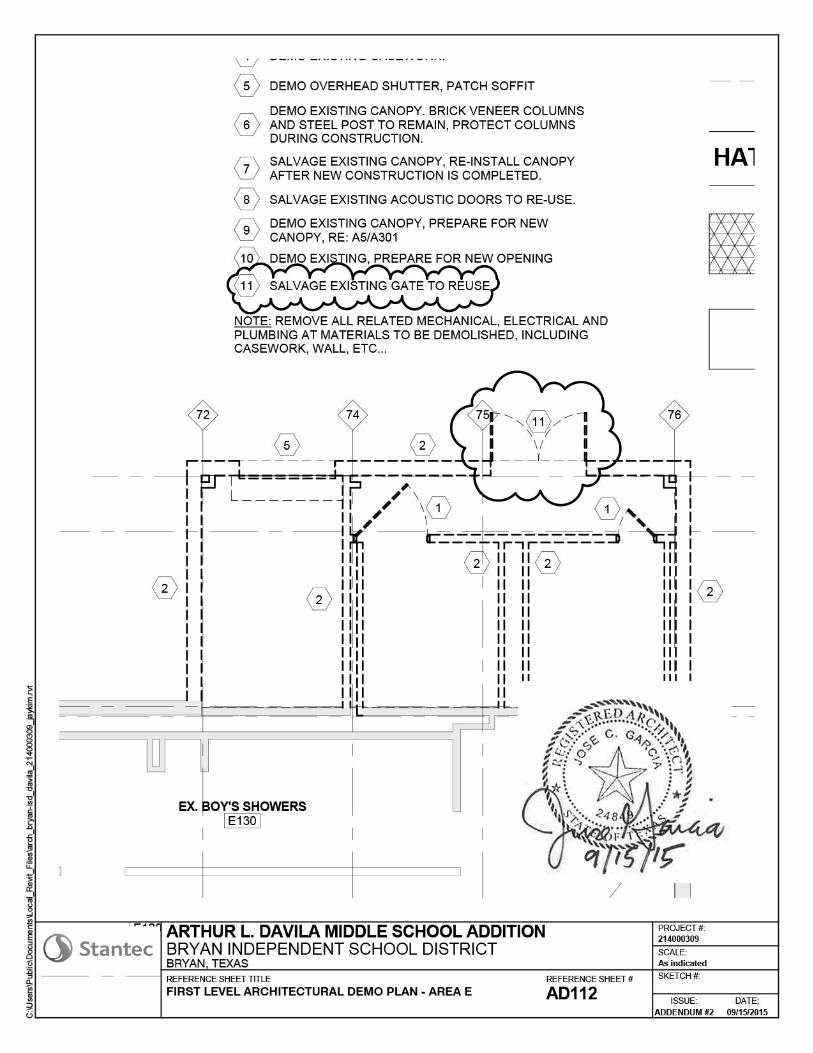
1. On plan sheet AD112, REVISION: Decorative metal gate door at outdoor restroom J121 is salvaged and re-used.

Project Name: Davila Middle School Addition Date: September 15, 2015 Addendum No. Two (02) Page 4 of 4
2. On plan sheet A011, CLARIFICATION: Dimension at existing corridors is added. New accent LVT areas are indicated.
3. On plan sheet A113, REVISION: Expansion joint systems on floor and wall.
4. On plan sheet A501, REVISION: Aluminum window frame is revised.
Mechanial, Electrical, Plubming, Technology
1. See attached Addendum# 2 from DBR NUMBER OF ATTACHMENTS: Specifications – 8 ½” x 11” – 22 pages Sketches - 8 ½” X 11” – 14 pages Drawings – 42” X 30” – 1 sheet END OF ADDENDUM NUMBER TWO (02)

Davila Middle School Addition & Renovations September 15, 2015 Bryan Independent School District Addendum #2 214000 309
STANTEC RANKING CRITERIA FOR COMPETITIVE PROPOSALS 00 23 13 - 1
SECTION 00 23 13 - RANKING CRITERIA FOR COMPETITIVE PROPOSALS
1.1 GENERAL
A. The Owner shall use the following criteria for ranking the proposals and for designating the higher ranked Proposers with which it desires to negotiate. Upon ranking of the firms, the Owner shall enter into negotiations with the highest ranked proposer for a contract at a price acceptable to the Owner. If the negotiations are unsuccessful, the Owner may continue negotiating with Proposers in order of rank until a contract at a price acceptable to the Owner is agreed upon. The Owner reserves the right to exclude Proposers failing to achieve a minimum total score of 80 percent from any further consideration for negotiation. The highest ranking firm with which the Owner negotiates a contract at a price acceptable to the Owner will be deemed the Proposer offering the best value to the Owner.
Question – Criteria – Source – Scoring Procedures (Score – Factor – Total) 1 – Team Orientation – References – References are asked to evaluate the Contractor’s Teamwork 10 Points per Reference 1.0 Factor 10 Total Points Available Responses are scored as follows: Excellent = 10 points, "Very Good" = 8 points, "Average" = 6 points, "Fair" = 3 points, and "Poor" = 0 points. Preferred References (minimum 5) shall be provided BY PROPOSER in Qualification Documents. ARCHITECT AND OWNER WILL NOT SELECT INITIAL REFERENCES. In addition to 5 references selected by Proposer, Owner and Architect may select additional references. Responses from multiple references are averaged and compared with references of other Proposers 2 – Quality of Work – References – References are asked to evaluate the Contractor’s Quality of Work 10 Points per Reference 1.0 Factor 10 Total Points Available Responses are scored as follows: Excellent = 10 points, "Very Good" = 8 points, "Average" = 6 points, "Fair" = 3 points, and "Poor" = 0 points. Preferred References (minimum 5) shall be listed/provided BY PROPOSER in Qualification Documents. ARCHITECT AND OWNER WILL NOT SELECT INITIAL REFERENCES. In addition to 5 references selected by Proposer, Owner and Architect may select additional reference. Responses from multiple references are averaged and compared with references of other Proposers 3 – Maintaining Schedule – References – References are asked whether or not schedules were met 10 Points per Reference 1.0 Factor 10 Total Points Available Responses are scored as follows: "Completed ahead of schedule overcoming uncontrollable circumstances" = 10 points, "Completed ahead of schedule" = 8 points, "Completed on Schedule" = 6 points, "Completed less than two weeks behind schedule" = 3 points, and "Completed more than two

Davila Middle School Addition & Renovations September 15, 2015 Bryan Independent School District Addendum #2 214000 309
STANTEC RANKING CRITERIA FOR COMPETITIVE PROPOSALS 00 23 13 - 2
weeks behind schedule" = 0 points. Points from multiple references are averaged for the base score. Preferred References (minimum 5) shall be listed BY PROPOSER in Qualification Documents. ARCHITECT AND OWNER WILL NOT SELECT INITIAL REFERENCES. In addition to 5 references selected by Proposer, Owner and Architect may select additional reference. Responses from multiple references are averaged and compared with references of other Proposers 4 – Change Orders – References – References are asked to evaluate the Contractor on pricing received by Change Orders and other Proposal 10 Points per Reference 1.0 Factor 10 Total Points Available Responses are scored as follows: Excellent = 10 points, "Very Good" = 8 points, "Average" = 6 points, "Fair" = 3 points, and "Poor" = 0 points. Preferred References (minimum 5) shall be chosen BY PROPOSER in Qualification Documents. ARCHITECT AND OWNER WILL NOT SELECT INITIAL REFERENCES. In addition to 5 references selected by Proposer, Owner and Architect may select additional reference. Responses from multiple references are averaged and compared with references of other Proposers 5 – Warranty Work – References – References are asked whether or not warranty work was completed in a timely manner 10 Points per Reference 1.0 Factor 10 Total Points Available Responses are scored as follows: Excellent = 10 points, "Very Good" = 8 points, "Average" = 6 points, "Fair" = 3 points, and "Poor" = 0 points. Preferred References (minimum 5) shall be chosen BY PROPOSER in Qualification Documents. ARCHITECT AND OWNER WILL NOT SELECT INITIAL REFERENCES. In addition to 5 references selected by Proposer, Owner and Architect may select additional reference. Responses from multiple references are averaged and compared with references of other Proposers 6 – Client Satisfaction – References – References are asked whether or not they wish to work with the Contractor again 10 Points per Reference 1.0 Factor 10 Total Points Available Responses are scored as follows: "Definitely" = 10 points, "Probably" = 8 points, "Maybe" = 6 points, "Probably Not" = 3 points, "No" = 0 points. Preferred References (minimum 5) shall be chosen BY PROPOSER in Qualification Documents. ARCHITECT AND OWNER WILL NOT SELECT INITIAL REFERENCES. In addition to 5 references selected by Proposer, Owner and Architect may select additional reference. Responses from multiple references are averaged and compared with references of other Proposers

Davila Middle School Addition & Renovations September 15, 2015 Bryan Independent School District Addendum #2 214000 309
STANTEC RANKING CRITERIA FOR COMPETITIVE PROPOSALS 00 23 13 - 3
7 – Time in Business – AIA305 – Evaluation Team will acquire the year of establishment from the AIA305 submitted by Contractor (evaluation will be in years) 10 Points per Reference 1.0 Factor 10 Total Points Available Responses will be scored as follows: Responses are scored as follows: 0-1 years = 0 points, 2-3 years = 1 point, 4-5 years = 2 points, 6-7 years = 3 points, 8-9 years = 4 points, 10-11 years = 5 points, 12-13 years = 6 points, 14-15 years = 7 points, 16-17 years = 8 points, 18-19 years = 9 points, 20+ years = 10 points. 8 – Experience – AIA305 – Count Number of Projects of comparable size and scope completed by Proposer’s office within last ten years 10 Points per Reference 1.0 Factor 10 Total Points Available The evaluation team will score each contractor on a scale of 1-10 based on number of comparable projects completed. Responses are scored 1 point per project up to 10 9 – Proposed Team – Resumes for Project Manager and Project Superintendent will each be evaluated and points given to the team for the following; 36 Points per Reference .5 Factor 18 Total Points Available Time in the business (for each individually): 10+ years = 4 points, 8-9 years = 3 points, 5-7 years = 2 points, 2-4 years = 1 point, and less than 2 years = 0 points. Number of school projects completed (for each individually): 4+ = 4 points, 3 = 3 points, 2 = 2 points, 1 = 1 point, and none = 0 points. Time with the company (for each individually): 5+ years = 5 points, 4 years = 4 points, 3 years = 3 points, 2 years = 2 points, 1 year = 1 point, and less than year = 0 points Number of projects completed as a team: 5+ = 10 points, 4 = 8 points, 3 = 6 points, 2 = 4 points, 1 = 2 points, and less than one = 0 points. (Resumes) - Contractor to provide resumes and contact names and telephone numbers for references on applicable projects completed. 10 – Proposed Subcontractors – Alternate Proposal Form – Provide names of Proposed Concrete, Masonry, Roofing, and Mechanical, Electrical, and Plumbing Subcontractors 10 Points per Reference 1.0 Factor 10 Total Points Available Contractor shall submit a list of subcontractors that they intend to use on the project, more then one subcontractor can be submitted but not more then 2 for each category Substitutions will not be allowed without consent of Bryan ISD and the Architect Substitutions can affect the outcome of the evaluation (Proposal Form) – Sub-Contractor with no experience with District, Architect, or Architect’s Sub-Consultants will be given a score of 5. Good experience will be given a score of 6-10, bad experience will be given a score of 0-4 11 – Experience with Bryan ISD within the Past 10 Years – Proposal and AIA305 – Proposer provide to Owner a list of projects completed with Bryan ISD or it’s Agents of comparable

Davila Middle School Addition & Renovations September 15, 2015 Bryan Independent School District Addendum #2 214000 309
STANTEC RANKING CRITERIA FOR COMPETITIVE PROPOSALS 00 23 13 - 4
size and scope 10 Points per Reference 1.0 Factor 10 Total Points Available Contractors with no experience with Bryan or its agents will be given a score of 5 points; those with good experience will be given 6-10 points; those with bad experience will be given 0-4 points (List of Projects) - Contractor with no experience with District will be given a score of 5. Good experience will be given a score of 6-10, bad experience will be given a score of 0-4 ________________ Total Possible Score 118 Percentage Score 100.00%
1.2 PROPOSERS QUALIFICATIONS PACKAGES
A. In order for the Owner to properly evaluate each proposer’s qualifications, each proposer shall submit a Qualifications Package, with all required attachments and information, to the Architect by September 9, 2015.
B. All Proposers shall submit three hardcopies of the qualifications packet that will include AIA A305, “Contractors Qualification Statement,” and its required attachments and information, and the following: 1. The resume of the proposed Project Manager. 2. The resume of the proposed Superintendent. 3. A list of (5) references including names, fax numbers and email addresses
must be supplied. 4. A summary addressing the 11 ranking criteria to assist the Owner in his
evaluation.
1.3 PROCEDURES FOR FINAL RANKING AND NEGOTIATIONS
A. Once all Contractor proposals have been scored based upon the above criteria guidelines, each total score will be converted to a percentage grade of 0%-100% by dividing the total actual score by the total possible score. The contractor with the lowest proposed Base Proposal price plus selected Alternates and an evaluation grade of 80% or better will be ranked as the number one firm with each of the higher priced contractors (with a score of 80% or higher) given ranking of 2nd, 3rd, 4th, etc. In the event that no contractor receives a grade of 80% or better, the district at its option, will lower the minimum grade required in increments of 5% points as they deem to be needed and negotiate with those contractors in rank order of price.
1. NOTE: In the event that two or more contractors propose the same total price:
the contractor scoring highest on Question #11 will be ranked higher.
B. The Owner may make such investigations as he deems necessary and request additional information from the contractor to determine the ability of the proposer to perform the Work. The Proposer shall furnish all such information and data for the purpose as may be requested. The Owner reserves the right to reject any proposal if the evidence submitted by, or investigation of, such proposer fails to satisfy the Owner that such proposer is properly qualified to carry out the obligations of the Contract and to complete the Work contemplated above.

Davila Middle School Addition & Renovations September 15, 2015 Bryan Independent School District Addendum #2 214000 309
STANTEC RANKING CRITERIA FOR COMPETITIVE PROPOSALS 00 23 13 - 5
C. A committee consisting of Bryan ISD administrators and the Architect, and other staff will make an initial evaluation of the proposals to determine the number one ranked firm.
D. By submitting a proposal, each proposer agrees to waive any claim it has or may have against the Owner, the Architect/Engineer, and their respective employees, arising out or in connection with the administration, evaluation, or recommendation of any proposal; waiver of any requirements under the Proposal Documents or the Contact Documents; acceptance or rejection of any proposals; and award of the contract.
END OF SECTION

Davila Middle School Addition & Renovations September 15, 2015 Bryan Independent School District Addendum #2 214000 309
STANTEC PROPOSAL FORM (ALTERNATES PROPOSAL) 00 41 10 - 1
SECTION 00 41 10 - PROPOSAL FORM (ALTERNATES PROPOSAL) PROJECT: DAVILA MIDDLE SCHOOL ADDITIONS AND RENOVATIONS PLACE: BRYAN INDEPENDENT SCHOOL DISTRICT TRAVIS EDUCATIONAL SUPPORT SERVICES CENTER, ROOM 103 101 N. TEXAS AVENUE BRYAN, TEXAS 77803 DATE: SEPTEMBER 23, 2015 TIME: 3:00 PM TO: THE BOARD OF TRUSTEES, BRYAN INDEPENDENT SCHOOL DISTRICT Pursuant to and in compliance with the Invitation to Proposers and the proposed Contract Documents dated August 24, 2015, prepared by Stantec Architecture, relating to the above referenced project, the undersigned, hereby proposes and agrees to fully perform the work within the time stated and in strict accordance with the proposed Contract Documents, and addenda thereto, for the following sum of money: SUBCONTRACTOR SELECTIONS Pursuant to Requirements outlined in Section 00 23 13, Selection Criteria, the following are subcontractors performing major portions of the Work as indicated: Concrete____________________________________________ Masonry____________________________________________ Roofing_____________________________________________ Mechanical__________________________________________ Electrical____________________________________________ Plumbing____________________________________________ ALTERNATES The following are alternates to the Base Proposal: It is understood that if no figure is listed for an Alternate, that the Alternate may be accepted and there shall be no change in the Base Proposal amount indicated above. Strike out (add) or (deduct) as required for each alternate. Refer Division 1 Section "Alternates" for complete description of the alternates. ALTERNATE 1A: Vinyl Tile (LVT) flooring by Tandus for the primary and secondary corridors in the existing building. If the Owner elects to proceed with Alternate Number One A, (add) (deduct) the sum of: ______________________________________________________DOLLARS ($___________________)

Davila Middle School Addition & Renovations September 15, 2015 Bryan Independent School District Addendum #2 214000 309
STANTEC PROPOSAL FORM (ALTERNATES PROPOSAL) 00 41 10 - 2
ALTERNATE 1B: Vinyl Tile (LVT) flooring by MoHawk for the primary and secondary corridors in the existing building. If the Owner elects to proceed with Alternate Number One B, (add) (deduct) the sum of: ___________________________________________DOLLARS ($___________________) ALTERNATE 1C: Vinyl Tile (LVT) flooring by Mannington for the primary and secondary corridors in the existing building. If the Owner elects to proceed with Alternate Number One C, (add) (deduct) the sum of: ____________________________________________DOLLARS ($___________________) ALTERNATE 2A: Vinyl Tile (LVT) Flooring by Tandus in new construction as indicated on the Room Finish Schedule. There is no flooring of this type in the base bid. If the Owner elects to proceed with Alternate Number Two A, (add) (deduct) the sum of: __________________________________________________DOLLARS($___________________) ALTERNATE 2B: Vinyl Tile (LVT) Flooring by MoHawk in new construction as indicated on the Room Finish Schedule. There is no flooring of this type in the base bid. If the Owner elects to proceed with Alternate Number Two B, (add) (deduct) the sum of: ____________________________________________DOLLARS ($___________________) ALTERNATE 2C: Vinyl Tile (LVT) Flooring Mannington in new construction as indicated on the Room Finish Schedule. There is no flooring of this type in the base bid. If the Owner elects to proceed with Alternate Number Two C, (add) (deduct) the sum of: ____________________________________________DOLLARS($___________________) ALTERNATE 3A: New carpet by Tandus for the new construction areas as indicated on the Room Finish Schedule. There is no flooring of this type in the base bid. If the Owner elects to proceed with Alternate Number Three A, (add) (deduct) the sum of: _____________________________________________DOLLARS($___________________) ALTERNATE 3B: New carpet by MoHawk for the new construction areas as indicated on the Room Finish Schedule. There is no flooring of this type in the base bid. If the Owner elects to proceed with Alternate Number Three B, (add) (deduct) the sum of: ____________________________________________DOLLARS($___________________)

Davila Middle School Addition & Renovations September 15, 2015 Bryan Independent School District Addendum #2 214000 309
STANTEC PROPOSAL FORM (ALTERNATES PROPOSAL) 00 41 10 - 3
ALTERNATE 3C: New carpet by Mannington for the new construction areas as indicated on the Room Finish Schedule. There is no flooring of this type in the base bid. If the Owner elects to proceed with Alternate Number Three C, (add) (deduct) the sum of: __________________________________________________DOLLARS($___________________) ALTERNATE 4A: Trane Air Handling Units: Provide pricing for providing Trane Air Handling Units on the project. There are no AHU’s in the base bid. If the Owner elects to proceed with Alternate Number Four A, (add) (deduct) the sum of: __________________________________________________DOLLARS($___________________) ALTERNATE 4B: Temtrol Air Handling Units: Provide pricing for providing Temtrol Air Handling Units on the project. There are no AHU’s in the base bid. If the Owner elects to proceed with Alternate Number Four B, (add) (deduct) the sum of: ______________________________________________DOLLARS($___________________) ALTERNATE 4C: McQuay Air Handling Units: Provide pricing for providing McQuay Air Handling Units on the project. There are no AHU’s in the base bid. If the Owner elects to proceed with Alternate Number Four C, (add) (deduct) the sum of: ______________________________________________DOLLARS($___________________) ALTERNATE 5A: Trane Air Cooled Chillers: Provide pricing for providing Trane Air Cooled Chillers for the project that meet specifications and equipment schedule. There are no chillers in the base bid. If the Owner elects to proceed with Alternate Number Five A (add) (deduct) the sum of:
______________________________________________________DOLLARS ($___________________) ALTERNATE 5B: Artic Cool Air Cooled Chillers: Provide pricing for providing Air Cool Cooled Chillers for the project that meet specifications and equipment schedule. There are no chillers in the base bid. If the Owner elects to proceed with Alternate Number Five B (add) (deduct) the sum of: ______________________________________________________DOLLARS ($___________________) ALTERNATE 5C: York Air Cooled Chillers: Provide pricing for providing York Air Cooled Chillers for the project that meet specifications and equipment schedule. There are no chillers in the base bid. If the Owner elects to proceed with Alternate Number Five C , (add) (deduct) the sum of: ______________________________________________________DOLLARS ($___________________)

Davila Middle School Addition & Renovations September 15, 2015 Bryan Independent School District Addendum #2 214000 309
STANTEC PROPOSAL FORM (ALTERNATES PROPOSAL) 00 41 10 - 4
ALTERNATE 6A: HVAC Controls to be Reliable Controls provided by Unify. If the Owner elects to proceed with Alternate Number Six A, (add) (deduct) the sum of: ______________________________________________________DOLLARS ($___________________)
ALTERNATE 6B: HVAC Controls to be Delta Controls provided by Team Solutions.
If the Owner elects to proceed with Alternate Number Six B, (add) (deduct) the sum of:
______________________________________________________DOLLARS ($___________________)
ALTERNATE 7: Replace existing light fixtures with new LED type lighting at (15) locations.
If the Owner elects to proceed with Alternate Number Seven , (add) (deduct) the sum of: ______________________________________________________DOLLARS ($___________________)
ALTERNATE 8: Renovations to the existing Orchestra and existing Band rehearsal as indicated.
If the Owner elects to proceed with Alternate Number Eight, (add) (deduct) the sum of: ______________________________________________________DOLLARS ($___________________)
ALTERNATE 9: FFE for Choir stands for Choir rehearsal hall.
If the Owner elects to proceed with Alternate Number Nine, (add) (deduct) the sum of: ______________________________________________________DOLLARS($___________________)
ALTERNATE 10: FFE for Music Storage Cabinet for new Choir rehearsal hall. If the Owner elects to proceed with Alternate Number Ten, (add) (deduct) the sum of:
______________________________________________________DOLLARS ($___________________)
UNIT PRICES The following are unit prices. Refer to Division 1 Section "Unit Prices" for a complete description of unit prices. Provide only one price for additional or less amounts of each item indicated. Submission of more than one price may be grounds for rejection of Proposal.
Additional Reinforcing Steel - The undersigned agrees, in case of variation of quantities from those shown or specified, the following unit prices shall be used in adjusting the Contract Price. Reinforcing Steel, price per pound: $_____________________________________ Additional Speakers - The undersigned agrees, in case of variation of quantities from those shown or specified, the following unit prices shall be used in adjusting the Contract Price.

Davila Middle School Addition & Renovations September 15, 2015 Bryan Independent School District Addendum #2 214000 309
STANTEC PROPOSAL FORM (ALTERNATES PROPOSAL) 00 41 10 - 5
Additional Speakers, price per unit: $_____________________________________ Additional Typical Duplex Receptacles - The undersigned agrees, in case of variation of quantities from those shown or specified, the following unit prices shall be used in adjusting the Contract Price. Additional Receptacles, price per unit: $_____________________________________ Additional Wall Hydrant - The undersigned agrees, in case of variation of quantities from those shown or specified, the following unit prices shall be used in adjusting the Contract Price. Additional Wall Hydrant, price per unit: $_____________________________________ Additional Data Outlet Drops - The undersigned agrees, in case of variation of quantities from those shown or specified, the following unit prices shall be used in adjusting the Contract Price. Additional Data Outlet Drops, price per unit: $_____________________________________ Additional Security Door Contact - The undersigned agrees, in case of variation of quantities from those shown or specified, the following unit prices shall be used in adjusting the Contract Price. Additional Security Door Contacts, price per unit: $___________________________________ Additional Security Control Keypads - The undersigned agrees, in case of variation of quantities from those shown or specified, the following unit prices shall be used in adjusting the Contract Price. Additional Security Control Keypads, price per unit: $_________________________________ Additional Exit Sign with 50’ of wire – The undersigned agrees, in case of variation of quantities from those shown or specified, the following unit prices shall be used in adjusting the Contract Price.
Additional Exit Sign with 50’ of wire, price per unit: $ ______________________________
Additional Occupancy Sensor with powerpack – The undersigned agrees, in case of variation of quantities from those shown or specified, the following unit prices shall be used in adjusting the Contract Price.
Additional Occupancy Sensor with powerpack, price per unti: $
________________________ By execution and submission of this Proposal, the Proposer attests and affirms that he and his subcontractors are skilled and experienced in the use of plans, specifications, addenda and related bid documents, and that he has carefully reviewed the plans, specifications, addenda and related proposal documents for this project and has found them to be sufficient for proposal and construction purposes. Further, he has carefully examined the soils reports and the site of the work, and - through his own personal observations - has satisfied himself as to the nature, location and requirements of the work; the character, quality and quantity of materials required; the difficulties likely to be encountered; the other items and/or conditions which may affect the satisfactory performance of the work. He has based his proposal solely on these documents - and personal observations - and has not relied in any way on any explanation or interpretation - oral or written - from any source other than those written and issued by the Architect/Engineer.

Davila Middle School Addition & Renovations September 15, 2015 Bryan Independent School District Addendum #2 214000 309
STANTEC PROPOSAL FORM (ALTERNATES PROPOSAL) 00 41 10 - 6
Representations: by execution and submission of this Proposal, the Proposer hereby represents and warrants to the Owner as follows: The Proposer has read and understands the Proposal Documents and the Contract Documents and the
Proposal is made in accordance with the Proposal Documents. By submitting this Proposal, each Proposer agrees to waive any claim it has or may have against the Owner, the Architect/Engineer, and their respective employees arising out of or in connection with the administration, evaluation, or recommendation of any Proposal; waiver of any requirements under the Proposal Documents, or the Contract Documents; and award of the Contract. Proposer agrees that the Owner has the right to accept or reject any or all Proposals and to waive all informalities. Respectfully submitted, By:_________________________________________________ Signature ____________________________________________________ Title (Seal - if Proposer is a corporation) ____________________________________________________ Company ____________________________________________________ Address ____________________________________________________ City, State, Zip Code ____________________________________________________ Telephone Number ____________________________________________________ Email Address
END OF SECTION

Davila Middle School Addition & Renovations September 15, 2015 Bryan Independent School District Addendum #2 214000 309
STANTEC ALTERNATES 01 23 00 - 1
SECTION 01 23 00 - ALTERNATES PART 1 - GENERAL 1.1 RELATED DOCUMENTS
A. Drawings and general provisions of Contract, including General and Supplementary Conditions and other Division-1 Specification Sections, apply to this Section.
1.2 SUMMARY
A. This Section specifies administrative and procedural requirements for Alternates.
1. Definition: An Alternate is an amount proposed by Proposers and stated on the Proposal Form for certain construction activities defined in the Proposal Requirements that may be added to or deducted from Base Proposal amount if the Owner decides to accept a corresponding change in either the amount of construction to be completed, or in the products, materials, equipment, systems or installation methods described in Contract Documents.
2. Coordination: Coordinate related Work and modify or adjust adjacent Work as necessary to
ensure that Work affected by each accepted Alternate is complete and fully integrated into the project.
3. Notification: Immediately following the award of the Contract, prepare and distribute to each
party involved, notification of the status of each Alternate. Indicate whether Alternates have been accepted, rejected or deferred for consideration at a later date. Include a complete description of negotiated modifications to Alternates.
4. Schedule: A "Schedule of Alternates" is included at the end of this Section. Specification
Sections referenced in the Schedule contain requirements for materials and methods necessary to achieve the Work described under each Alternate.
a. Include as part of each Alternate, miscellaneous devices, accessory objects and similar
items incidental to or required for a complete installation whether or not mentioned as part of the Alternate.
b. The Owner reserves the right to accept any, none or all of the Alternates for a period of 30
days after receipt of proposals. Should the Owner-Contractor Agreement be executed prior to Owner acceptance of an Alternate, the Alternate will be accepted by Change Order at the original bid amount within 30 days after receipt of proposals.
PART 2 - PRODUCTS (Not Applicable). PART 3 - EXECUTION 3.1 SCHEDULE OF ALTERNATES
A. ALTERNATE 1A: Vinyl Tile (LVT) flooring by Tandus for the existing primary and secondary corridors
as indicated.

Davila Middle School Addition & Renovations September 15, 2015 Bryan Independent School District Addendum #2 214000 309
STANTEC ALTERNATES 01 23 00 - 2
B. ALTERNATE 1B: Vinyl Tile (LVT) flooring by MoHawk for the existing primary and secondary corridors as indicated.
C. ALTERNATE 1C: Vinyl Tile (LVT) flooring by Mannington for the existing primary and secondary corridors as indicated.
D. ALTERNATE 2A: Vinyl Tile (LVT) flooring by Tandus in new construction as indicated on the Room Finish Schedule. There is no flooring of this type in the base bid.
E. ALTERNATE 2B: Vinyl Tile (LVT) flooring by MoHawk in new construction as indicated on the Room Finish Schedule. There is no flooring by Mannington of this type in the base bid.
F. ALTERNATE 2C: Vinyl Tile (LVT) flooring in new construction as indicated on the Room Finish Schedule. There is no flooring of this type in the base bid
G. ALTERNATE 3A: New carpet by Tandus for the new construction areas as indicated on the Room Finish Schedule. There is no flooring of this type in the base bid.
H. ALTERNATE 3B: New carpet by MoHawk for the new construction areas as indicated on the Room Finish Schedule. There is no flooring of this type in the base bid
I. ALTERNATE 3C: New carpet by Mannington for the new construction areas as indicated on the Room Finish Schedule. There is no flooring of this type in the base bid
J. ALTERNATE4A: Trane Air Handling Units: Provide pricing for providing Trane Air Handling Units on the project. There are no AHU’s in the base bid.
K. ALTERNATE 4B: Temtrol Air Handling Units: Provide pricing for providing Temtrol Air Handling Units on
the project. There are no AHU’s in the base bid.
L. ALTERNATE 4C: McQuay Air Handling Units: Provide pricing for providing McQuay Air Handling Units on the project. There are no AHU’s in the base bid.
M. ALTERNATE 5A: Trane Air Cooled Chillers: Provide pricing for providing Trane Air Cooled Chillers for the project that meet specifications and equipment schedule. There are no chillers in the base bid.
N. ALTERNATE 5B: Artic Cool Air Cooled Chillers: Provide pricing for providing Artic Cool Air Cooled Chillers for the project that meet specifications and equipment schedule. There are no chillers in the base bid.
O. ALTERNATE 5C: York Air Cooled Chillers: Provide pricing for providing York Air Cooled Chillers for the project that meet specifications and equipment schedule. There are no chillers in the base bid.
P. ALTERNATE 6A: HVAC Controls to be Reliable Controls provided by Unify.
Q. ALTERNATE 6B: HVAC Controls to be Delta Controls provided by Team Solutions.
R. ALTERNATE 7: Replace existing light fixtures with new LED type lighting at (15) locations.
S. ALTERNATE 8: Renovations to the existing Orchestra and existing Band rehearsal as indicated.
T. ALTERNATE 9: FFE for Choir stands for Choir rehearsal hall.
U. ALTERNATE 10: FFE for Music Storage (16”Wx44”Dx8’H) Cabinet for Choir rehearsal hall. END OF SECTION

Davila Middle School Addition & Renovations September 15, 2015 Bryan Independent School District Addendum #2 214000 309
STANTEC
PREMANUFACTURED EXPANSION JOINT SYSTEMS07 95 00 - 1
SECTION 07 95 00 - PREMANUFACTURED EXPANSION JOINT SYSTEMS
PART 1 - GENERAL
1.1 SUMMARY
A. Section Includes: The following types of metal expansion joint covers: 1. Interior pedestrian traffic joints. 2. Interior wall and ceiling joints. 3. Interior soffit joints.
B. Related Sections: 1. Section 03 30 00 - Cast-In-Place Concrete: Block-outs and cast-in anchorage and
frames for expansion joint systems in concrete floors, parking decks, and walls. 2. Section 07 62 00 - Sheet Metal Flashing and Trim: Sheet metal roof and wall joint
systems. 3. Section 07 90 00 - Joint Protection; Elastomeric sealants and preformed
compressed-foam sealants without metal frames.
1.2 DEFINITIONS
A. Expansion Joint System: Any filler or cover used to span, fill, cover, or seal a joint, except expanding foam seals and applied sealants.
B. Cyclic Movement: Periodic change between widest and narrowest joint widths in an automatically mechanically controlled system.
C. Fire Barriers: Any material or material combination, when fire tested after cycling, designated to resist passage of flame and hot gases through a movement joint.
D. Movement Capability: Value obtained from the difference between widest and narrowest widths of a joint opening typically expressed in numerical values (mm or inches) or a percentage of nominal value of joint width.
E. Revise below if it is impossible either to indicate nominal joint widths based on a prediction when the joint system will be installed or, if none is indicated, to establish them based on maximum and minimum joint widths.
F. Nominal Joint Width: Width of linear gap indicated as representing the conditions existing when expansion joint systems will be installed or, if no nominal joint width is indicated, a width equal to the sum of maximum and minimum joint widths divided by two.
1.3 PERFORMANCE REQUIREMENTS
A. General: Provide factory-fabricated expansion joint systems capable of withstanding the types of loads and of accommodating the kinds of movement, and the other functions for which they are designed including those specified below, without failure. Types of failure include those listed in Appendix X3 of ASTM E 1399. 1. Pedestrian Traffic Joints: Support pedestrian traffic across joint. 2. Joints in Fire-Resistance-Rated Assemblies: Maintain fire-resistance ratings of
assemblies. 3. Joints in Smoke Barriers: Maintain integrity of smoke barrier. 4. Joints in Acoustically Rated Assemblies: Inhibit passage of airborne noise. 5. Other Joints: Where indicated, provide joint systems that prevent penetration of
water, moisture, and other substances deleterious to building components or content.
6. Seismic Joints: Remain in place on exposure to seismic activity (movement).

Davila Middle School Addition & Renovations September 15, 2015 Bryan Independent School District Addendum #2 214000 309
STANTEC
PREMANUFACTURED EXPANSION JOINT SYSTEMS07 95 00 - 2
7. Joints in Surfaces with Architectural Finishes: Serve as finished expansion joint closures.
1.4 SUBMITTALS
A. Product Data: Include manufacturer's product specifications, construction details, material and finish descriptions, and dimensions of individual components and seals.
B. Shop Drawings: For each joint system specified, provide the following: 1. Placement Drawings: Include line diagrams showing entire route of each joint
system, plans, elevations, sections, details, joints, splices, locations of joints and splices, and attachments to other Work. Where joint systems change planes, provide Isometric Drawings depicting how components interconnect to achieve continuity of joint covers and fillers.
C. Samples for Verification: Full-size units 6 inches (150 mm) long of each type of joint system indicated; in sets for each finish, color, texture, and pattern specified, showing the full range of variations expected in these characteristics.
D. Product Test Reports: From a qualified testing agency indicating expansion joint systems comply with requirements, based on comprehensive testing of current products.
E. Research/Evaluation Reports: Evidence of expansion joint system's compliance with building code in effect for Project, from a model code organization acceptable to authorities having jurisdiction.
1.5 QUALITY ASSURANCE
A. Source Limitations: Obtain expansion joint systems through one source from a single manufacturer. Coordinate compatibility with adjoining joint systems specified in other Sections.
B. Fire-Test-Response Characteristics: Where indicated, provide joint systems incorporating fire barriers that are identical to those of assemblies tested for fire resistance per ASTM E 119 and UL 2079, including hose-stream test of vertical wall assemblies, by a testing and inspecting agency acceptable to authorities having jurisdiction.
PART 2 - PRODUCTS
2.1 MANUFACTURERS
A. Basis-of-Design Products: The design for each expansion joint system specified in Part 2 "Expansion Joint Systems" Article below is based on the products named. Subject to compliance with requirements, provide either the named products or comparable products by one of the other manufacturers listed.
2.2 MATERIALS
A. Aluminum: ASTM B 221 (ASTM B 221M), alloy 6063-T5 for extrusions; ASTM B 209 (ASTM B 209M), alloy 6061-T6 for sheet and plate. 1. Apply manufacturer's standard protective coating on aluminum surfaces to be
placed in contact with cementitious materials.
B. Preformed Seals: Single or multicellular extruded elastomeric seals designed with or without continuous, longitudinal, internal baffles. Formed to be installed in frames or with anchored flanges, in color indicated or, if not indicated, as selected by Architect from

Davila Middle School Addition & Renovations September 15, 2015 Bryan Independent School District Addendum #2 214000 309
STANTEC
PREMANUFACTURED EXPANSION JOINT SYSTEMS07 95 00 - 3
manufacturer's standard colors.
C. Fire Barriers: Any material or material combination, when fire tested after cycling, designated to resist the passage of flame and hot gases through a movement joint.
D. Accessories: Manufacturer's standard anchors, clips, fasteners, set screws, spacers, flexible moisture barrier and filler materials, drain tubes, lubricants, adhesives, and other accessories compatible with material in contact, as indicated or required for complete installations.
2.3 PREMANUFACTURED EXPANSION JOINT SYSTEMS
A. General: Provide joint systems of design, basic profile, materials, and operation indicated. Provide units with the capability to accommodate joint widths indicated and variations in adjacent surfaces. 1. Furnish units in longest practicable lengths to minimize number of end joints.
Provide hairline mitered corners where joint changes directions or abuts other materials.
2. Include closure materials and transition pieces, tee-joints, corners, curbs, cross-connections, and other accessories as required to provide continuous joint systems.
3. Public Arena Seals: Non-slip seals designed for installation on treads and risers and to lie flat with adjacent surfaces, and complying with ADA guidelines for public areas.
4. Nominal Joint Widths: As indicated. 5. Type of Movement Capability: Expansion and contraction. 6. Preformed Seal Material: Manufacturer's standard.
a. Seal Color: Selected by Architect. 7. Exposed Frame Material: Aluminum. 8. Fire-Resistance Ratings: For joint systems at rated conditions, provide
manufacturer's standard fire barrier with a rating not less than that of adjacent construction.
B. Basis-of-Design Products: The design for each expansion joint system specified below is based on the products named. Subject to compliance with requirements, provide either the named products or comparable products by one of the following manufacturers: 1. Architectural Art Manufacturing, Inc. www.archart.com 2. Balco Metalines, www.balcousa.com 3. Construction Specialties, Inc. www.c-sgroup.com 4. InPro Corp. www.inprocorp.com. 5. MM Systems, Inc. www.mmsystemscorp.com
C. Expansion Joint System: Metal frames and preformed seals for the following interior conditions: 1. Floor-to-Floor Joints, Basis-of-Design Product: Construction Specialties, Inc.;
“ALS” Series. 2. Floor-to-Wall Joints, Basis-of-Design Product: Construction Specialties, Inc.;
“ALSW” Series. 3. Wall-to-Wall Joints, Basis-of-Design Product: Construction Specialties, Inc.; “AFW”
Series. 4. Wall-to-Ceiling Joints, Basis-of-Design Product: Construction Specialties, Inc.;
“FCSC” Series 5. Ceiling-to-Ceiling Joints, Basis-of-Design Product: Construction Specialties, Inc.;
“FCS” Series. 6. Wall-to-Soffit Joints, Basis-of-Design Product: Construction Specialties, Inc.;

Davila Middle School Addition & Renovations September 15, 2015 Bryan Independent School District Addendum #2 214000 309
STANTEC
PREMANUFACTURED EXPANSION JOINT SYSTEMS07 95 00 - 4
“FCSC” Series. 7. Soffit-to-Soffit Joints, Basis-of-Design Product: Construction Specialties, Inc.;
“FCS” Series.
2.4 FINISHES, GENERAL
A. Comply with NAAMM's "Metal Finishes Manual for Architectural and Metal Products" for recommendations for applying and designating finishes.
B. Protect mechanical finishes on exposed surfaces from damage by applying a strippable, temporary protective covering before shipping.
2.5 ALUMINUM FINISHES
A. Finish designations prefixed by AA comply with the system established by the Aluminum Association for designating aluminum finishes.
B. Mill Finish: AA-M10 (Mechanical Finish: as fabricated; no other applied finish unless buffing is required to remove scratches, welding, or grinding produced in fabrication process. 1. Provide at floor conditions unless otherwise indicated.
C. Class II, Clear Anodic Finish: AA-M12C22A31
1. Mechanical Finish; nonspecular as fabricated.
2. Chemical Finish: Etched, medium matte.
3. Anodic Coating: Architectural Class II, clear coating 0.010 mm or thicker complying with AAMA 607.1.
4. Provide at wall, ceiling, and soffit conditions unless otherwise indicated.
PART 3 - EXECUTION
3.1 PREPARATION
A. Prepare substrates according to expansion joint system manufacturer's written instructions.
B. Coordinate and furnish anchorages, Placement Drawings, and instructions for installing joint systems to be embedded in or anchored to concrete or to have recesses formed into edges of concrete slab for later placement and grouting-in of frames.
C. Fastening to In-Place Construction: Provide anchorage devices and fasteners where necessary to secure joint systems to in-place construction, including threaded fasteners with drilled-in expansion shields for masonry and concrete where anchoring members are not embedded in concrete. Provide fasteners of metal, type, and size to suit type of construction indicated and to provide for secure attachment of joint systems.
3.2 INSTALLATION
A. Comply with manufacturer's written instructions for handling and installing expansion joint assemblies and materials, unless more stringent requirements are indicated.
B. Coordinate installation of expansion joint assembly materials and associated work so complete assemblies comply with assembly performance requirements.
C. Cutting, Fitting, and Placement: Perform cutting, drilling, and fitting required to install joint systems.

Davila Middle School Addition & Renovations September 15, 2015 Bryan Independent School District Addendum #2 214000 309
STANTEC
PREMANUFACTURED EXPANSION JOINT SYSTEMS07 95 00 - 5
1. Install joint cover assemblies in true alignment and proper relationship to joints and adjoining finished surfaces measured from established lines and levels.
2. Allow adequate free movement for thermal expansion and contraction of metal to avoid buckling.
3. Set covers in horizontal surfaces at elevations that place exposed surfaces flush with adjoining finishes.
4. Locate wall, ceiling, and soffit covers in continuous contact with adjacent surfaces. 5. Securely attach in place with required accessories. 6. Locate anchors at interval recommended by manufacturer, but not less than 3
inches from each end and not more than 24 inches o.c.
D. Continuity: Maintain continuity of joint systems with a minimum number of end joints and align metal members. Cut and fit ends to produce joints that will accommodate thermal expansion and contraction of metal to avoid buckling of frames. Adhere flexible filler materials, if any, to frames with adhesive or pressure-sensitive tape as recommended by manufacturer.
E. Extruded Preformed Seals: Install seals to comply with manufacturer's written instructions and with minimum number of end joints. 1. For straight sections, provide preformed seals in continuous lengths. 2. Vulcanize or heat-weld field splice joints in preformed seal material to provide
watertight joints using procedures recommended by manufacturer. 3. Apply adhesive, epoxy, or lubricant adhesive approved by manufacturer to both
frame interfaces before installing preformed seals. 4. Seal transitions according to manufacturer's written instructions.
F. Seismic Seals: Install interior seals in continuous lengths. Install exterior seal in standard lengths and vulcanize or heat-weld field splice joints to provide watertight joints using manufacturer's recommended procedures. Seal transitions and end joints according to manufacturer's written instructions.
G. Fire Barriers: Install fire barriers to provide continuous, uninterrupted fire resistance throughout length of joint, including transitions and end joints.
3.3 CLEANING AND PROTECTION
A. Do not remove protective covering until finish work in adjacent areas is complete. When protective covering is removed, clean exposed metal surfaces to comply with manufacturer's written instructions.
END OF SECTION

Davila Middle School Addition & Renovations September 15, 2015 Bryan Independent School District Addendum #2 214000 309
STANTEC
PORTABLE SEATING RISER SYSTEM11 61 23 - 1
SECTION 11 61 23 – PORTABLE SEATING RISER SYSTEM
PART 1 - GENERAL
1.1 SUMMARY
A. Section Includes: 1. Shop manufactured portable platform systems specifically designed and manufactured for
use as temporary seating risers.
1.2 REFERENCES
A. American Hardboard Association
1. AHA A135.4: Basic Hardboard.
B. IBC and ASTM Load Ratings Standards:
1. 2009 International Building Code; SECTION 1607 LIVE LOADS; TABLE 1607.1 MINIMUM UNIFORMLY DISTRIBUTED LIVE LOADS AND MINIMUM CONCENTRATED LIVE LOADS. (Uniform loading in PSF for Stages and platforms in Assembly areas and theaters).
2. 2009 International Building Code; SECTION 1604 GENERAL DESIGN REQUIREMENTS; TABLE 1604.3 DEFLECTION LIMITS (Deflections for floor members as l/XXX).
3. 2009 International Building Code; SECTION 1714 IN-SITU LOAD TESTS; SECTION
1714.3.2 Load test procedure not specified. (24 hour duration test at 2x design load).
4. ASTM E2322-03 Standard Test Method for Conducting Transverse and Concentrated Load Tests on Panels used in Floor and Roof Construction Section 10 (Applying uniform load via air bag) Section 11 (Applying concentrated load via 25.4mm diameter pin, measurement method, max load).
5. ASTM E661-03 Standard Test Method for Performance of Wood and Wood-Based Floor and
Roof Sheathing Under Concentrated and Impact Loads. Section 4,6 (Applying concentrated load via 25mm & 76mm diameter loading disks, loading location).
6. ASTM Standard for Stair and Tred Loads.
C. ASTM International
1. ASTM B 221: Specification for Aluminum and Aluminum-Alloy Extruded Bars, Rods, Wire, Profiles, and Tubes.
2. ASTM B 429: Specification for Aluminum-Alloy Extruded Structural Pipe and Tube.
3. ASTM B85: Standard Specification for Aluminum Alloy Die Castings.
4. ASTM A513: Standard Specification for Electric-Resistance-Welded Carbon and Alloy Steel Mechanical Tubing.
5. ASTM A1011: Standard Specification for Steel, Sheet and Strip, Hot Rolled, Carbon,
Structural, High-Strength Low Alloy, High-Strength Low Alloy With Improved Formability, and Ultra High Strength.

Davila Middle School Addition & Renovations September 15, 2015 Bryan Independent School District Addendum #2 214000 309
STANTEC
PORTABLE SEATING RISER SYSTEM11 61 23 - 2
D. NFPA International
1. NFPA 701: Fire Tests for Flame-Resistant Textiles and Films.
E. US Green Building Council (USGBC):
1. Leadership in Energy and Environmental Design (LEED) Green Building Rating System..
1.3 PERFORMANCE REQUIREMENTS
A. Structural Performance: 1. Stage Platforms and Risers: Standard Uniform Load 4’X8’ Deck: 125 lbf/ft. 2 (6 kN/ m2).
Heavy-Duty Uniform Load 4’X8’ Deck with additional 5th leg: 200 lbf/ft. 2 (9.6 kN m2).
2. Stage Platforms and Risers: Dynamic Live Load: Side load of 15% of total Uniform Live Load: 600lb (2.7 kN) side load on a 4’ X 8’ platform under a total Uniform Live Load of 4,000 lbs (17.8 kN).
3. Stage Platforms and Risers: Fully replaceable components including corners, frame and
wood deck. Replaceable in the field with common tools.
4. Guard Rail Concentrated Load: 200 lbf (0.89 kN) applied at any point in any direction.
5. Guard Rail Uniform Load: 50 lbf/ft. (0.73 kN/m) applied to top rail.
6. Intermediate Rails, Panels, and Baluster Concentrated Load: 50 lbf (0.22 kN) applied to 1 sq. ft. (0.093 sq. m) area.
1.4 SUBMITTALS
A. Section 01 33 00 - Submittal Procedures: Submittal procedures.
B. Product Data: Manufacturer’s data sheets and installation instructions.
C. Shop Drawings: Prepared by manufacturer. Include elevations showing components and details of each condition of installation. Show fabrication and installation details and relationship to adjacent work. Include plans, elevations, sections, details, and relationship to other work.
1.5 QUALITY ASSURANCE
A. Installer Qualifications: An authorized representative of system manufacturer for installation and maintenance of system units required for this Project.
B. Source Limitations: Obtain portable stage system through one source from a single manufacturer.
C. Product Designations: Shop drawings to indicate sizes, configurations, and finish material of deck panels, legs, railings, hardware, and accessories by referencing designated manufacturer's catalog numbers.
D. Equal Products: Other manufacturers' systems of similar sizes and configurations, of same finish material, and complying with these Specifications may be considered.
1.6 DELIVERY, STORAGE, AND HANDLING
A. Section 01 60 00 - Product Requirements: Product storage and handling requirements.
B. Deliver portable stage system only after painting, utility roughing-in, and similar operations have been completed that could damage, soil, or deteriorate system construction or finishes. Store
Davila Middle School Addition & Renovations September 15, 2015 Bryan Independent School District Addendum #2 214000 309
STANTEC
PORTABLE SEATING RISER SYSTEM11 61 23 - 3
system components only in areas where environmental conditions meet requirements specified in "Project Conditions" Article.
C. Keep finished surfaces covered with polyethylene film or other protective covering during handling and installation.
1.7 WARRANTY
A. Section 01 70 00 - Execution and Closeout Requirements: Product warranties and product bonds.
B. Special Warranty: Manufacturer's five-year written warranty agreeing to repair or replace components of portable stage system components or accessory parts that fail in materials or workmanship. Failures include, but are not limited to, the following: 1. Delamination of components or other failures of glue bond. 2. Warping or sagging of components not resulting from leaks or flooding. 3. Fracturing or breaking of unit components which results from normal wear and tear and
normal use other than vandalism. 4. Failure of operating hardware. 5. Deterioration of finishes.
1.8 PROJECT CONDITIONS
A. Environmental Limitations: Do not deliver or install system until building is enclosed, wet work is complete, and HVAC system is operating and maintaining temperature and relative humidity at occupancy levels during the remainder of the construction period.
B. Field Measurements: Where field measurements cannot be made without delaying the Work, coordinate dimensions with the Contractor to ensure that actual dimensions correspond to established dimensions.
PART 2 - PRODUCTS
2.1 MANUFACTURERS
A. Wenger Corp., www.wengercorp.com B. Substitutions: Section 01 60 00 - Product Requirements.
2.2 SYSTEM DESCRIPTION
A. Basis of Design: StageTek Seated Riser system as manufactured by Wenger or approved equivalent.
B. Type: Prefabricated deck panels with removable legs at progressive heights to form riser seating. System panels, legs, and railings shall be transportable on specified carts.
2.3 COMPONENTS
A. Frame: Extruded 6063-T6 aluminum, 4 inches with hidden contours to accept attachments. Rounded 1.5” hand-hold area open to accept power-grip around entire perimeter. 1. Corners: Cast 380 aluminum corner assembly engages leg 3-inches and secures leg with a
full-length 2.75 inches convex brace driven by a threaded bolt operated with a nylon t-handle. 2. Legs: Constructed of extruded 6063-T6 aluminum round tube, 2.50 inch diameter x 0.075
inch thick with non-marking end cap. a. Provide standard fixed-height legs in the various heights as indicated in the drawings. b. Legs to store resting on frame rails or in clamping brackets within deck frames.
B. Deck Panels:

Davila Middle School Addition & Renovations September 15, 2015 Bryan Independent School District Addendum #2 214000 309
STANTEC
PORTABLE SEATING RISER SYSTEM11 61 23 - 4
1. Minimum 5/8-inch thick plywood substrate with finish surface of manufacturer’s standard textured polypropylene with black smooth HDPE backer sheet. a. Panels edged with extruded mill finish aluminum trim. b. Shapes and Dimensions: Manufacturer’s standard shapes and dimensions as required
for configuration indicated.
C. Included Accessories 1. Guard Railings: Factory finished steel tube railings meeting specified performance
requirements and all applicable codes. a. Lower horizontal rail acts as chair stop. b. Clamp attached to rear of deck panels without tools.
2. Stabilizing Braces: Provide for system heights 40” or greater.
3. Deck Locks: Provide deck-to-deck cam locks built into deck frames to ensure
4. Leg Storage Clips: Provide bottom-of-deck panel leg storage clips to provide storage of 4 legs per each panel.
5. Closure Panels: Closure panels matching deck surface finish. Minimum 3/4-inch thick plywood secured with tool-free snap attachment located at front and sides of risers.
6. Fabric Skirting: Manufacturer's standard stage-drapery-fabric with hanging accessories for rear skirting of system. Black color.
7. Storage Carts: System manufacturer’s steel tube-framed folding transport carts with heavy-duty 8-inch casters and clamping safety strap. Cart designed to carry up to 6 decks or 6 guardrails, or a combination of both.
a. Provide number of carts required for deck panels and guardrails required for the layout indicated.
PART 3 - EXECUTION
3.1 SYSTEM INSTALLATION
A. Assemble and install complete system in configuration and location indicated on the drawings.
B. Make all necessary adjustments to system for proper operation and safety.
C. Install hardware uniformly and precisely. Adjust and align locking hasps so moving parts operate freely and contact points meet accurately. Allow for final adjustment after installation.
D. Lubricate casters for smooth and noiseless operation.
3.2 TRAINING
A. Train Owner's personnel in the proper assembly, adjusting, loading to carts, and maintenance of system.
B. Provide copies of printed operation and maintenance instructions to Owner.
3.3 CLEANING AND PROTECTION
A. Repair or remove and replace defective work as directed on completion of installation.
B. Clean finished surfaces, touch up as required, and remove or refinish damaged or soiled areas to match original factory finish, as approved by Architect.
C. Disassemble units following approval and store on carts in location as indicated by the Owner.
END OF SECTION


41
AR
42
43
AS
44
45 46
47 48 49
50
51
52 53
BG
BF
54 56 58 60 62
6261595755
63
BE
BD
BC
64
BB
BA
AZ
AY
AP
AN
65
66 67
68
69 70 71 72 73 74 75 76 77
38.1
36
33
29
24
20
RA
18
16
15
13
11
8
7
6
3
2
1
4
5
9
10
12
RB.K.
L
J.H.
G.F
E.D.
M.N.
P.
RS
TU.
V
W
Y
ZAA
AB
14
17
19
21
22
23
40
BJ
BL
BN
BP
BR
BS
BM
BK
BH
25
26
27
28
30
31
X
37
3839
RFRG
34
32
35
AJ
AK
AL
AM
AH
AG
AF
AE
AD
AC
AX
AV
AU
AW
AT
RE
A202
A1
A201E1
69.8 7876.1
BU
BV
71.3 75.472.1
BJ.0
BK.9
BM.9
BN.9
BP.8
BT
74.9
A201
A1
AN.1
BD.9
77.945.4 49.948.9
AN.2
AR.9
76.2
A201 G1
A201
A8
A202D5
A202 D1
A1A111
A5A111
E9A111
A8A113
A8A112
/A8 A113
/A8 A112
A201C1
A1A711
96
PRACTICEA122
CHOIRA150
ENSEMBLEA151
OFFICEA152
CORRIDORA131
BLACK BOXB134
NEW LIFE SKILLSF104
I.S.S.E133
MECHANICALE134
WEIGHT ROOME136
STORAGEE138
VESTIBULEE135
BOILER ROOME139
CORRIDORJ100
CLASSROOM 1J101
CLASSROOM 2J102
CLASSROOM 3J103
READINGJ104
REPLACEMENT 803J105
REPLACEMENT 805J106
WAITINGJ107
V.P. OFFICEJ108
ELECT.J109
I.T.J110
CUST.J111
CORRIDORJ112
BOYSJ113
STAFF TOILETJ114
GIRLSJ115
TECH APP.J116
SCIENCE 2J117
PREPARATIONJ118
SCIENCE 1J119
MENSJ121
WOMENSJ122
CLASSROOM 4J123
CLASSROOM 5J124
CLASSROOM 6J125
FORIEGN LANGUAGEJ126
REPLACEMENT 812J127
RESOURCE 1J128
RESOURCE 2J129
CORRIDORJ120
CORRIDORJ147
EX. BOY'S SHOWERSE130
EX. BOY'S LOCKERSE129
EX. VEST.E122
FITNESS ROOME123
PRACTICE A124BA124B
BAND REHEARSAL (E)
STORAGEB134E
LIFE SKILLS TOILETF105
KITCHENETTEF106
UNIFORM STORAGEA154
STORAGEA153
PRACTICE A124AA124A
BAND STORAGE (E)A125
BAND LIBRARY (E)
ORCH. STORAGE (E)
PRACTICEA144
PRACTICE (E)A140
PRACTICE (E)A135
ELECT. (E) OFFICEA129
OFFICEA127
OFFICEE137
??
CORRIDORC108
??
PRINCIPAL OFFICEB102
CONFERENCEB120
OFFICEB122
RECEPTIONB105
EX. GIRLS LOCKERE103
EX. GIRLS SHOWERSE102
STORAGEE136A
WOODSHOP STORAGEH109A
A732E8
A1AS002
A201-A
A7
A201-A F1
A201-AE1
A201-A
C1
A201-A
A1
A201-AA5
A201-A C5
TYP.
(+/-) 10' - 0"
TYP.
(+/-)
14'
- 0"
TYP .
(+/-)
123
' - 0
"
(+/-) 254'-0"
(+/-) 18'- 6
"
TYP.
(+/-) 28' - 0"
(+/-) 81' - 0"
(+/-) 120' - 0
"
(+/-) 120' - 0"
(+/-)
172
' - 0
"
(+/-) 123' - 0"
(+/-) 66' - 6"
(+/-)
8 ' -
6"
TYP.
(+/-)
10'
- 0"
?
?
TYP.
12' - 0"
TYP.
9' -
0"
TYP .
9' -
0"
TYP.
6' - 0"
TYP.
7' -
6"
TYP.
9' - 0"
ALIGN, TYP..
GENERAL PROJECT NOTES1 ALL WORK TO BE PERFORMED IN COMPLIANCE WITH ALL APPLICABLE CODES, LAWS & REGULATIONS INCLUDING OWNER REQUIREMENTS & THOSE REQUIREMENTS ASSOCIATED WITH UNITED STATES GREEN BUILDING COUNCIL'S LEED CERTIFICATION.
2 PROTECT ADJACENT AREAS FROM DUST, EXCESSIVE NOISE & / OR DISRUPTION OF OPERATION. ANY WORK WHICH INTERFERES WITH THE OWNER'S OPERATION OF THE SURROUNDING AREAS & ANY INTERUPTION OF SERVICES INCLUDING THE SHUTDOWN OF UTILITIES SHALL BE PERFORMED AT A TIME APPROVED BY THE OWNER'S REPRESENTATIVE.
3 PROVIDE INTERIOR AND/OR EXTERIOR SHORING, BRACING OR SUPPORT AS REQUIRED TO PREVENT MOVEMENT, SETTLEMENT, DAMAGE OR COLLAPSE OF STRUCTURE WITHIN CONTRACT LIMITS.
4 PROVIDE TEMPORARY BARRICADES & OTHER FORMS OF PROTECTION AS REQUIRED TO PROTECT OWNER'S PERSONNEL & GENERAL PUBLIC FROM INJURY DUE TO DEMOLITION WORK. PROVIDE A PROPER MEANS OF EGRESS AS REQUIRED FOR OCCUPIED AREAS PER CODE DURING CONSTRUCTION. EGRESS MUST ALSO BE MAINTAINED WITHIN THE CONSTRUCTION AREA.
5 THE SPECIFICATIONS AND DRAWINGS ARE INTENDED TO DESCRIBE AND PROVIDE FOR A COMPLETED PIECE OF WORK. THE CONTRACTOR SHALL FURNISH ALL LABOR AND EQUIPMENT NECESSARY FOR THE WORK AS CONTEMPLATED BY THE SPECIFICATIONS AND DRAWINGS. IT IS UNDERSTOOD AND AGREED BY THE CONTRACTOR THAT THE WORK DESCRIBED SHALL BE COMPLETE IN EVERY DETAIL, EVEN THOUGH EVERY ITEM NECESSARILY INVOLVED IS NOT PARTICULARLY MENTIONED.
6 THIS PROJECT INVOLVES CONSTRUCTION ADJACENT TO AN EXISTING STRUCTURE. CONTRACTORS, BY SUBMITTING A BID, ARE ASSUMED TO BE COMPLETELY FAMILIAR WITH THE EXISTING CONDITIONS OF THE BUILDING AS IT INFLUENCES THE WORK DESCRIBED IN THE CONSTRUCTION DOCUMENT. ABSOLUTELY NO CLAIMS FOR EXTRA COST WILL BE CONSIDERED FOR EXISTING CONDITIONS VISIBLE OR REASONABLY INFERABLE FROM A CAREFUL EXAMINATION OF THE EXISTING BUILDING.
7 NOTIFY THE ARCHITECT IMMEDIATELY IF A HIDDEN FIELD CONDITION IS UNCOVERED OR A DISCREPENCY IN THE CONTRACT DOCUMENTS IS FOUND THAT CONFLICTS WITH THE INTENDED FINAL PRODUCT & REQUIRES MODIFICATIONS TO THE LAYOUT.
CONSTRUCTION LEGEND:
CFMF WALLS (REFER TO WALL TYPES)
CMU WALLS (REFER TO WALL TYPES)
EXISTING AREA - NO WORK
EXISTING WALL
ALTERNATE
RENOVATED AREA
FLOOR MATERIAL LEGEND:
LVT-2 (ACCENT) IN THIS AREA
EXACT LOCATIONS OF NEW ACCENT LVT TO MATCHEXISTING.LVT-1(FILED) TO BE INSTALLED THROUGHOUT SCOPEOF WORK AREA U.O.N. PER ROOM SCHEDULE
N
E
DC
AB
FG
H
J
1
ISSUE:
CHECKED:
SCALE:
Project #:
SHEET TITLE:
KEY PLAN (NTS)
Final Plans for Bidding and Construction
2 3 4 5 6 7 8 9 10
1 2 3 4 5 6 7 8 9 10
H
G
F
E
D
C
B
A
H
G
F
E
D
C
B
A
DRAWN:
20 EAST GREENWAY PLAZASUITE 200
HOUSTON, TEXAS 77046
P 713.548.5700F 713.548.5701
C:\U
sers
\Pub
lic\D
ocum
ents
\Loc
al_R
evit_
File
s\ar
ch_b
ryan
-isd_
davi
la_2
1400
0309
_jay
kim
.rvt
9/16
/201
5 1:
32:1
3 PM
As indicatedChecker
BRYAN INDEPENDENTSCHOOL DISTRICT
ARTHUR L. DAVILA MIDDLESCHOOL ADDITION
BRYAN, TEXAS
COMPOSITE FIRST LEVELPLAN - NEW &RENOVATION WORK
A011214000309
8/24/15
Author
1" = 20'-0"A1COMPOSITE FIRST LEVEL PLAN - NEW WORK
N
ADD 1
2
ADD 1
2
ADD 1
2
ADD 1
2
ADD 1
2
ADD 1
2
ADD 1
2
ADD 1
2
ADD 1
2
ADD 1
2
ADD 1
2
ADD 1
2
ADD 1
2
ADD 1
2
ADD 1
2
ADD 1
2
ADD 1
2
ADD 1
2
ADD 1
2
ADD 1
2
ADD 1
2
ADD 1
2
1 09/15/2015 ADDENDUM #2

9990 Richmond AvenueSouth Building, Suite 300
Houston, TX 77042
v 713.914.0888f 713.914.0886
www.dbrinc.com
Addendum
HOUSTON | SAN ANTONIO | MCALLEN | CORPUS CHRISTI | AUSTIN TBPE Firm Registration No. 2234
DATE September 15, 2015 ADDENDUM NO. 2 PROJECT #150096.000 | Arthur L. Davila Middle School Addition The work described herein shall be added to the scope of work defined by the contract documents or it shall modify the scope of work defined by the contract documents as described. This work shall become a part of the contract documents by addendum. SPECIFICATIONS Item 01 Specification Section 23 09 63 – ENERGY MANAGEMENT AND CONTROLS SYSTEM (EMCS)
A. Revised acceptable manufacturer to read as follows: 1. ALERTON – OpenTech Systems
Item 02 Specification Section 23 52 16 – CONDENSING BOILER – GAS FIRED
A. Added HYDROTHERM – KN series as an acceptable manufacturer. B. Removed Camus as an acceptable manufacturer. C. Added Lochinvar – Crest boiler as an acceptable manufacturer.
Item 03 Specification Section 21 13 13 – WET PIPE SPRINKLER SYSTEM
A. Part 2 – Products, Article 2.2 Submittals, Paragraph G. Materials, Subparagraph 3a, change to read as follows: Provide approved automatic sprinkler valve with one or two pole (as required) flow detectors, pressure switch, outside electric gong, inside electric gong and circuit breaker.
Item 04 Specification Section 22 10 00 – PLUMBING PIPING
A. Part 2 – Products, Article 2.15 Ball Valves, Paragraph A. Manufacturers, Subparagraph 2, change to read: Watts. Delete subparagraphs 2a, b, c, and d.
Item 05 Specification Section 22 30 00 – PLUMBING EQUIPMENT
A. Part 2 – Products, Article 2.1 Commercial Electric Water Heaters, Paragraph A. Manufacturers, Subparagraph 2, change to read: Rheem. Delete subparagraphs 2a, b, and c.
Item 06 Specification Section 27 10 00 – STRUCTURED CABLING SYSTEM (SCS)
A. 1.3 Quality Assurance / B / 2 shall be revised as follows: The SCS Installer shall be a Certified, local area, integrator of the manufacturer’s product and must be able to provide the manufacturer’s maximum available warranty for the solution on the entire SCS. The contractor’s certification must have been obtained and held within 120 miles of the project’s location.

P a g e | 2 of 9
Addendum No. 2
HOUSTON | SAN ANTONIO | MCALLEN | CORPUS CHRISTI | AUSTIN TBPE Firm Registration No. 2234
B. 1.3 Quality Assurance / B / 6 shall be deleted in its entirety. Contractors that meet the
requirements of these specifications are permitted to propose on the scope designated within these specifications and associated drawings.
C. 2.5 Station Hardware / A / 1. / a. shall be deleted in its entirety. Reference Attachment ‘A’ for this information.
D. Attachment ‘A’ Project Specific Scope of Work and Instructions / 1.2 Structured Cabling System – Additional Instructions / A. / 1 Base Proposal, shall be revised as follows: The SCS Installer shall provide and install a complete End-to-End Structured Cabling System as per these specifications and associated drawings. The Base bid SCS shall consist of:
E. Attachment ‘B’ Manufacturer, Material, and Installer List / Structured Cabling Solution Manufacturer’s Representative: Revise list as follows:
MANUFACTURER REPRESENTATIVE EMAIL PHONE NUMBER
CommScope Stan Bludau [email protected] (713) 516-7017
Panduit Jonathan Cowen [email protected] (713) 828-0873
Contractor pricing a pre-approved equivalent shall provide pricing based on the exact parameters of the base specified product. The project’s consultant shall review the alternate product, at the submittal phase, to verify that the product is comparable in quality and functionality. The projects consultant shall reserve the right to decline use of submitted product based on product equivalence. Contractor may submit proposed equivalent product to the project’s consultant prior to proposal date for pre-approval. Proposed equivalents submitted for review must be received by the project’s consultant no later than ten (10) days prior to the proposal date.
Item 07 Specification Section 27 41 16 INSTRUCTIONAL AUDIO/VIDEO SYSTEM
A. 2.2 Audio/Video Display Device shall be revised to read as follows: (Indicated with ‘WMP’, ‘AVO’, ‘LED’, ‘DS’, or projector icon designation on drawings)
Provide video display pricing as alternate to base bid. Reference Specification Section 01 23 00. All cabling infrastructure shall remain as part of the base proposal.
A. All Audio/Video Displays and Sound Reinforcement shall be provided and installed by the
contractor
B. Displays 1. Projector:
a. Provide Wall mounted projectors where indicated on drawings. Wall mounted projectors shall be Epson Brightlink 485Wi Interactive WXGA 3LCD Projector with wall mount.
2. Interactive LED Touch Panel Display: a. Provide Newline Interactive 80” TruTouch LED/Touch Screen Display Monitor,
Product No. TT-8014B (EPR8A00080-000), at each ‘AVO’ outlet on the entire project. 1) Provide and install one (1) TruTouch 800/840 wall mount at each location.
Product No. EPR8A50600-000 3. Portable LED Display:

P a g e | 3 of 9
Addendum No. 2
HOUSTON | SAN ANTONIO | MCALLEN | CORPUS CHRISTI | AUSTIN TBPE Firm Registration No. 2234
Provide a portable Audio/Video Display Station at all locations designated on the contract drawings. Provide one (1) additional for level 1 and one (1) additional for level 2. Each portable display shall consist of the following: a. One (1) Newline Interactive 80” TruTouch LED/Touch Screen Display Monitor,
Product No. TT-8014B (EPR8A00080-000) b. One (1) TruTouch 550/650/800 Mobile Stand, Product No. EPR8A50500-000 c. One (1) 4-port power strip, Tripp•Lite Product No. PS-415-HG d. One (1) power strip mounting bracket, Tripp•Lite Product No. PSCLAMP. (Utilize
power strip mounting to mount the power strip onto each portable display station)
B. 2.4 Audio-Video System Wiring and Terminating Hardware
A. / 2. Revise ‘WMP’ to read ‘AVO' B. / 1 and 2. Revise ‘WMP’ to read ‘AVO’
Item 08 Specification Section 28 13 00 – ACCESS CONTROL SYSTEM
A. 2.5 Wiring / G / 1, revise as follows: Access control, plenum, composite cable – 22/6 shielded, 18/4, 18/2, 18/4 Tappan or equivalent
Item 09 Specification Section 28 31 00 – FIRE DETECTION AND NOTIFICATION SYSTEM
A. 2.1 Manufacturer / D, shall be revised as follows: The Following Panels will be used for this project’s applications. 1. EST3 Series Panels 2. Notifier Equivalent
DRAWINGS Item 10 Sheet M211 – LEVEL 1 MECHANICAL PLAN – AREA A, B & F
A. Added motorized damper to return air of plenum mixing box for AHU-3. B. Added return air grille in Conference Room B120.
Item 11 Sheet M212 – LEVEL 1 MECHANICAL PLAN – AREA E
A. Added volume damper in return air duct for AHU-2. B. Added motorized damper on return air plenum box for AHU-1. C. Revised boiler specifications. Exhaust flue shall be 4” diameter per manufacturer specifications.
Gas load shall be 1,000 CFH. Hot water design flow rate shall be 69.8 gpm. D. Added 6” diameter combustion air intake vent for boiler B-1. Install per manufacturer’s
instruction manual.
Item 12 Sheet M213 – LEVEL 1 MECHANICAL PLAN – AREA J
A. Added four (4) return air boots with fire smoke dampers. RE: SKM-1/SKM-2 B. Added fire smoke dampers on inlet ducts of DDMB-1-9, DDMB-1-15, and DDMB-1-18 at rated
wall. RE: SKM-1/SKM-2 C. Added Thermostat in IT J110 for FCU-1.
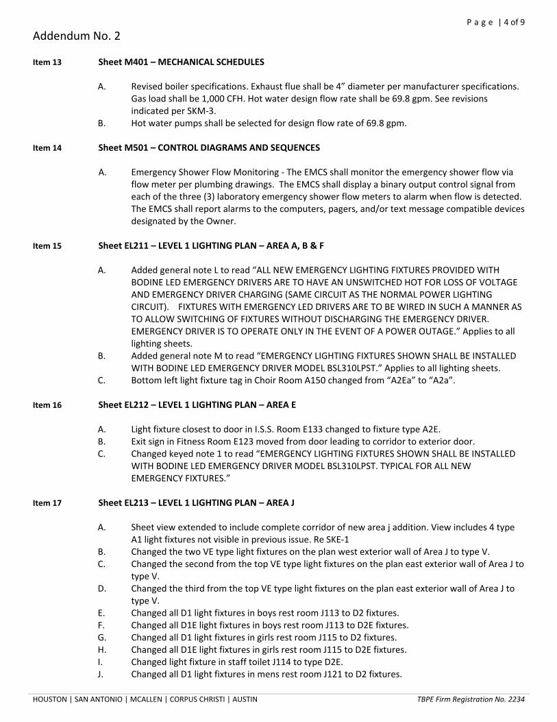
P a g e | 4 of 9
Addendum No. 2
HOUSTON | SAN ANTONIO | MCALLEN | CORPUS CHRISTI | AUSTIN TBPE Firm Registration No. 2234
Item 13 Sheet M401 – MECHANICAL SCHEDULES
A. Revised boiler specifications. Exhaust flue shall be 4” diameter per manufacturer specifications. Gas load shall be 1,000 CFH. Hot water design flow rate shall be 69.8 gpm. See revisions indicated per SKM-3.
B. Hot water pumps shall be selected for design flow rate of 69.8 gpm. Item 14 Sheet M501 – CONTROL DIAGRAMS AND SEQUENCES
A. Emergency Shower Flow Monitoring - The EMCS shall monitor the emergency shower flow via flow meter per plumbing drawings. The EMCS shall display a binary output control signal from each of the three (3) laboratory emergency shower flow meters to alarm when flow is detected. The EMCS shall report alarms to the computers, pagers, and/or text message compatible devices designated by the Owner.
Item 15 Sheet EL211 – LEVEL 1 LIGHTING PLAN – AREA A, B & F
A. Added general note L to read “ALL NEW EMERGENCY LIGHTING FIXTURES PROVIDED WITH BODINE LED EMERGENCY DRIVERS ARE TO HAVE AN UNSWITCHED HOT FOR LOSS OF VOLTAGE AND EMERGENCY DRIVER CHARGING (SAME CIRCUIT AS THE NORMAL POWER LIGHTING CIRCUIT). FIXTURES WITH EMERGENCY LED DRIVERS ARE TO BE WIRED IN SUCH A MANNER AS TO ALLOW SWITCHING OF FIXTURES WITHOUT DISCHARGING THE EMERGENCY DRIVER. EMERGENCY DRIVER IS TO OPERATE ONLY IN THE EVENT OF A POWER OUTAGE.” Applies to all lighting sheets.
B. Added general note M to read “EMERGENCY LIGHTING FIXTURES SHOWN SHALL BE INSTALLED WITH BODINE LED EMERGENCY DRIVER MODEL BSL310LPST.” Applies to all lighting sheets.
C. Bottom left light fixture tag in Choir Room A150 changed from “A2Ea” to “A2a”.
Item 16 Sheet EL212 – LEVEL 1 LIGHTING PLAN – AREA E
A. Light fixture closest to door in I.S.S. Room E133 changed to fixture type A2E. B. Exit sign in Fitness Room E123 moved from door leading to corridor to exterior door. C. Changed keyed note 1 to read “EMERGENCY LIGHTING FIXTURES SHOWN SHALL BE INSTALLED
WITH BODINE LED EMERGENCY DRIVER MODEL BSL310LPST. TYPICAL FOR ALL NEW EMERGENCY FIXTURES.”
Item 17 Sheet EL213 – LEVEL 1 LIGHTING PLAN – AREA J
A. Sheet view extended to include complete corridor of new area j addition. View includes 4 type A1 light fixtures not visible in previous issue. Re SKE-1
B. Changed the two VE type light fixtures on the plan west exterior wall of Area J to type V. C. Changed the second from the top VE type light fixtures on the plan east exterior wall of Area J to
type V. D. Changed the third from the top VE type light fixtures on the plan east exterior wall of Area J to
type V. E. Changed all D1 light fixtures in boys rest room J113 to D2 fixtures. F. Changed all D1E light fixtures in boys rest room J113 to D2E fixtures. G. Changed all D1 light fixtures in girls rest room J115 to D2 fixtures. H. Changed all D1E light fixtures in girls rest room J115 to D2E fixtures. I. Changed light fixture in staff toilet J114 to type D2E. J. Changed all D1 light fixtures in mens rest room J121 to D2 fixtures.
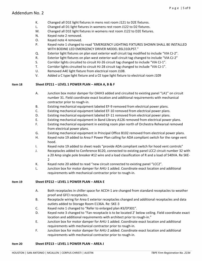
P a g e | 5 of 9
Addendum No. 2
HOUSTON | SAN ANTONIO | MCALLEN | CORPUS CHRISTI | AUSTIN TBPE Firm Registration No. 2234
K. Changed all D1E light fixtures in mens rest room J121 to D2E fixtures. L. Changed all D1 light fixtures in womens rest room J122 to D2 fixtures. M. Changed all D1E light fixtures in womens rest room J122 to D2E fixtures. N. Keyed note 2 removed. O. Keyed note 4 removed. P. Keyed note 1 changed to read “EMERGENCY LIGHTING FIXTURES SHOWN SHALL BE INSTALLED
WITH BODINE LED EMERGENCY DRIVER MODEL BSL310LPST.” Q. Exterior light fixtures on plan east exterior wall circuit tag modified to include “VIA CJ-2”. R. Exterior light fixtures on plan west exterior wall circuit tag changed to include “VIA CJ-2” S. Corridor lights circuited to circuit HJ-26 circuit tag changed to include “VIA CJ-1”. T. Corridor lights circuited to circuit HJ-28 circuit tag changed to include “VIA CJ-1”. U. Removed A4E light fixture from electrical room J108. V. Added a C type light fixture and a CE type light fixture to electrical room J109
Item 18 Sheet EP211 – LEVEL 1 POWER PLAN – AREA A, B & F
A. Junction box motor damper for OAIH3 added and circuited to existing panel “LA1” on circuit number 31. Field coordinate exact location and additional requirements with mechanical contractor prior to rough-in.
B. Existing mechanical equipment labeled EF-9 removed from electrical power plans. C. Existing mechanical equipment labeled EF-10 removed from electrical power plans. D. Existing mechanical equipment labeled EF-11 removed from electrical power plans. E. Existing mechanical equipment in Band Library A126 removed from electrical power plans. F. Existing mechanical equipment in existing room plan north of Orchestra Rehearsal removed
from electrical power plans. G. Existing mechanical equipment in Principal Office B102 removed from electrical power plans. H. Keyed note 19 added to Area F Power Plan calling for ADA compliant switch for the range vent
hood. I. Keyed note 19 added to sheet reads “provide ADA compliant switch for hood vent controls” J. Receptacles added to Conference B120, connected to existing panel LCC2 circuit number 32 with
a 20 Amp single pole breaker #12 wire and a load classification of R and a load of 540VA. Re SKE-2
K. Keyed note 20 added to read “new circuit connected to existing panel “LCC2”. L. Junction box for motor damper for AHU-1 added. Coordinate exact location and additional
requirements with mechanical contractor prior to rough-in.
Item 19 Sheet EP212 – LEVEL 1 POWER PLAN – AREA E A. Both receptacles in chiller space for ACCH-1 are changed from standard receptacles to weather
proof and GFCI receptacles. B. Receptacle wiring for Area E exterior receptacles changed and additional receptacles and data
outlets added to Storage Room E136A. Re: SKE-3 C. Keyed note 1 changed to “Refer to enlarged plan #3/EP301”. D. Keyed note 3 changed to “Fan receptacle is to be located 2’ below ceiling. Field coordinate exact
location and additional requirements with architect prior to rough-in.” E. Junction box for motor damper for AHU-1 added. Coordinate exact location and additional
requirements with mechanical contractor prior to rough-in. F. Junction box for motor damper for AHU-2 added. Coordinate exact location and additional
requirements with mechanical contractor prior to rough-in.
Item 20 Sheet EP213 – LEVEL 1 POWER PLAN – AREA J

P a g e | 6 of 9
Addendum No. 2
HOUSTON | SAN ANTONIO | MCALLEN | CORPUS CHRISTI | AUSTIN TBPE Firm Registration No. 2234
A. Circuit tag for EF-6 changed to “LJ1-67” refer to panel schedule changes for more information. B. Motor for overhead coiling door added and circuited to panel “LJ1” on circuit number 69. Install
keyed switches on both sides of the door. Re SKE-4 C. Added approximate location of existing pullbox. Re SKE-5 D. Added new conduit and relocated pullbox for football stadium. Re SKE-5
Item 21 Sheet EP231 –ELECTRICAL ROOF PLAN – AREA E & F
A. Keyed note 1 added to OAIH-1 B. Keyed note 1 added to OAIH-2 C. Receptacle added at location of OAIH-1 circuited to panel “LJ1” on circuit 66. Refer to panel
schedule sheet for wiring information. D. Receptacle added at location of EF-5 circuited to panel “LJ1” on circuit 66. Refer to panel
schedule sheet for wiring information.
Item 22 Sheet EP232 –ELECTRICAL ROOF PLAN – AREA J A. Receptacle added at location of EF-1 circuited to panel “LJ1” on circuit 66. Refer to panel
schedule sheet for wiring information. B. Receptacle added at location of EF-2 circuited to panel “LJ1” on circuit 66. Refer to panel
schedule sheet for wiring information. C. Receptacle added at location of EF-3 circuited to panel “LJ1” on circuit 66. Refer to panel
schedule sheet for wiring information. D. Receptacle added at location of EF-4 circuited to panel “LJ1” on circuit 66. Refer to panel
schedule sheet for wiring information.
Item 23 Sheet E401 – ELECTRICAL ONELINE DIAGRAM A. Deleted SPD-1 from the SPD Schedule. B. Transformer schedule added. Re SKE-6 C. Black box dimming equipment feeder changed to the following, 3 #3, 1 #1/0 Neutral and 1 #8
Ground. All in a single 1¼in conduit.
Item 24 Sheet E402 – ELECTRICAL DETAILS AND SCHEDULES A. Revise lighting fixture schedule per revised sheet. B. Added transformer detail. Re SKE-7 C. Added lighting contactor schedule. Re SKE-7 D. At lighting fixture schedule, change manufacturer of type “L” to Pathway Coventry Series. E. At lighting fixture schedule, changed all emergency fixture descriptions. Re SKE-2
Item 25 Sheet E501 – ELECTRICAL PANEL SCHEDULES
A. Motor Damper added to existing panel “LA1” circuit number 31. Circuit has 20 Amp single pole breaker and #12 wire, load classification is misc and the load is 250VA.
B. Circuit number 41 on existing panel LC2 corrected, circuit has a 20 Amp single pole breaker with #12 wire.
C. EF-6 added to panel schedule for panel LJ1 on circuit 67 with a 15 Amp single pole breaker with #12 wire and a load of 528VA and a load classification of F.
D. Panel “HJ” information changed to say 1 Section panel.

P a g e | 7 of 9
Addendum No. 2
HOUSTON | SAN ANTONIO | MCALLEN | CORPUS CHRISTI | AUSTIN TBPE Firm Registration No. 2234
E. Panel “LJ1” MCB changed to 250 Amps and MLO changed to 400 Amp F. Roof receptacles added to panel “LJ1” refer to Roof sheets for receptacle locations. Circuit
connected to circuit 66 with #12 wire and a 20 Amp breaker. Load classification R and a load of 1080VA.
G. SPD on panel “LJ2” circuits 80,82,84 removed and changed to spaces. H. Panel “LJ2” MCB changed to 250 Amps and MLO changed to 400 Amp I. Panel “LJ2” MCB changed to 250 Amps and MLO changed to 400 Amp J. Motor damper circuit added to circuit “LJ1-71” with a 20 Amp single pole breaker #12 wire m
classification and a load of 250. K. Motor damper circuit added to circuit “LJ1-73” with a 20 Amp single pole breaker #12 wire m
classification and a load of 250. L. Motor damper circuit added to circuit “LA1-32” with a 20 Amp single pole breaker #12 wire m
classification and a load of 250. Item 26 Alternate Manufacturers:
A. The lighting fixture package submitted by Putterman, Scharck & Associates is acceptable for use on this project with the exception of fixture types A4, A4E, N1, N2, V and VE. Also, emergency fixtures are to be provided with LED battery driver in lieu of transfer devices. Davila MS does not have an emergency generator.
Item 27 Sheet P211 – LEVEL 1 PLUMBING PLAN – AREA A,B, & F
A. Detail 2 Level 1 Plumbing Plan – Area B: Change sink SK-2 to SK-1 and change sink SK-1 to SK-2. B. Keyed notes: Note 17, change new total connected load to 7,420 CFH.
Item 28 Sheet P212 – LEVEL 1 PLUMBING PLAN – AREA E A. Keyed notes: Note 15, change CFH to 1,000 CFH.
Item 29 Sheet P213 – LEVEL 1 PLUMBING PLAN – AREA J A. Detail 1 Level 1 Plumbing Plan – Area J, Science Room I J119: Change sink SK-4 on north wall to
SK-3. Change south sink SK-3 on west wall to SK-4. B. Detail 1 Level 1 Plumbing Plan – Area J, Science Room 2 J117: Change sink SK-4 on south wall to
SK-3. Change north sink SK-3 on east wall to SK-4. Item 30 Sheet P402 – PLUMBING FIXTURE SPECIFICATION, NOTES, AND SCHEDULES
A. Add fixture EDF-1, Description: wall hung, barrier free, split-level electric drink fountain, all stainless steel, NSF/ANSI 61 lead-free design. Shall deliver 8 GPH of 50 degree water at 90 degree ambient and 80 degree inlet water. Provide cane touch apron in all stainless steel on all units mounted with a clear knee space greater than 27” high. Halsey Taylor HAC8FSBL-Q ADA with 98324C apron. Unit must deliver un-chilled water without power. P-trap: 1-1/4” 17 gauge chrome plated heavy cast brass trap with cleanout and extension to wall with escutcheon plate. McGuire 8872. Supplies: 1/2” IPS x 3/8” OD chrome plated loose key stop valve with escutcheon and 3/8” compression chrome plated flexible riser. McGuire 2165LK. Carrier: Three rectangular steel tubing uprights with welded 3”x4-1/2” feet anchored to concrete slab with (4) 1/2" bolts and anchors at each foot. Universal plate assemblies with hardware, and bearing plates with studs. MIFAB MC-33-2. Rough-in: 2”waste, 2” vent, 1/2" cold water. Refer to architectural drawings for height requirements.
B. SK-X5, change Rough-in to read: 2” sanitary waste. 2” acid vent, 1/2" cold water. Refer to architectural drawings for height requirements.
C. FD-1, change manufacturer to read: WADE 1100-A6-1.

P a g e | 8 of 9
Addendum No. 2
HOUSTON | SAN ANTONIO | MCALLEN | CORPUS CHRISTI | AUSTIN TBPE Firm Registration No. 2234
D. FD-2, change Description to read: Floor drain, bottom outlet cast iron body, adjustable 9” diameter ductile iron slotted grate, anchor flange, 1/2" trap primer tap, sediment bucket. Provide clamping device for drains in membrane floor areas. WADE 1300-12-27.
E. FD-3, change manufacturer to read: WADE 1100-A6-EF6-1. F. FS-3, change manufacturer to read: WADE 9140-1-6-15-26-48. G. WCO, change description to read: Wall cleanout. Cast iron cleanout ferrule, countersunk brass
plug and 6” round stainless steel cover plate with center securing screw. Provide cast iron cleanout tee in lieu of ferrule as required for wall construction. WADE 8550-75 or WADE 8560-75 with WADE 8304-6-VP.
H. FCO, change description to read: Floor cleanout, cast iron body with threaded adjustable housing, ferrule with taped brass plug, and round scoriated nickel bronze cover with security screws. Provide carpet marker where required. WADE 8130-1-VP.
I. ECO, change description to read: Exterior cleanout to grade, cast iron body with threaded adjustable housing, ferrule with tapered brass plug, and round scoriated heavy duty cover with security screws. If located in asphalt or dirt provide 18”x18”12” concrete pad. WADE 6000-VP-75-X.
J. HB-1, change description to read: Hose bibb. Exposed type wall faucet with 3/4" FPT inlet, 3/4” male hose thread outlet and self-draining anti-siphon vacuum breaker. Rough chrome plated brass finish, cast iron wheel handle. MIFAB HY-9131.
K. ESEW-1, add Flow Switch monitoring as follows: Provide a GEMS FS-200 series in-line flow switch, capable of flows ranging from 3-30 GPM. Provide removable 150 micron in-line filtration upstream of switch. Flow switch shall be located in exposed or readily accessible supply piping to fixture. Provide all required associated wiring to serve switch and to provide remote monitoring of switch via building automation system.
Item 31 Sheet F211 – Level 1 Fire Alarm Plan – Area A, B, & F
A. Delete intercom system ceiling mounted speakers and wall mounted volume controls in
Principal Office B102 B. Delete fire alarm visual notification strobe in Principal Office B102 C. Delete exterior fire alarm audible horn notification and intercom wall mounted speaker, located
outside Principal Office B102 D. Delete fire alarm notification strobe and intercom ceiling mounted speaker in Waiting B102 E. Delete intercom wall mounted volume control and ceiling mounted speaker in Office B122 F. Delete fire alarm ceiling mounted visual strobe in Office B122 G. Delete the subscript ‘a’ associated with all smoke detectors. H. Add one (1) fire alarm ceiling mounted visual strobe in each of the three room’s located plan
west of Orchestra Rehearsal A136. Pricing for these devices shall be included as Alternate Pricing for this area. Reference specifications section 01 23 00 for additional instructions.
I. Add one (1) fire alarm ceiling mounted smoke detector in the larger of the three room’s located plan west of Orchestra Rehearsal A136. Pricing for these devices shall be included as Alternate Pricing for this area. Reference specifications section 01 23 00 for additional instructions.
J. Add one (1) intercom ceiling mounted speaker in each of the three room’s located plan west of Orchestra Rehearsal A136. Pricing for these devices shall be included as Alternate Pricing for this area. Reference specifications section 01 23 00 for additional instructions.
Item 32 Sheet F212 – Level 1 Fire Alarm Plan – Area E
A. Remove the subscript ‘a’ from all smoke detectors on this sheet.
Item 33 Sheet F213 – Level 1 Fire Alarm Plan – Area J

P a g e | 9 of 9
Addendum No. 2
HOUSTON | SAN ANTONIO | MCALLEN | CORPUS CHRISTI | AUSTIN TBPE Firm Registration No. 2234
A. Remove the subscript ‘a’ from all smoke detectors on this sheet.
Item 34 Sheet T211 – Level 1 Technology Plan – Area A, B, & F
A. Revise Front Entrance and Administration area, shown in detail 2, as per the attached sketch SK-
T-1.
END OF ADDENDUM

3a 3b
OC OC
→→ →
FITNESS ROOME123
EX. CORRIDORE100
HJ-13
EXEXEX
EXEX
EXEX
X2
A1
A1 A1
A1
A1
A1 A1 A1
A1A1E
EXEXEX
EX
EX6
6 6
6 6
6
HJ-33VIA CJ-2
VE
55
5 55
5
2
2
2
DRAWN BY:
PROJECT:
CHECKED BY:
DBR PROJECT NO:
DWG. REF.
DRAWING
NUMBER
DATE:
RE:
713.914.0888 p
713.914.0886 f
9990 Richmond Avenue
South Building, Suite 300
Houston, Texas 77042
BRYAN I.S.D
TBPE Firm Registration No. 2234 ADDENDUM 2
ARTHUR L. DAVILA MIDDLE SCHOOL ADDITION
150096.000
WM
09/15/15 AJ
SKE-1
EL213
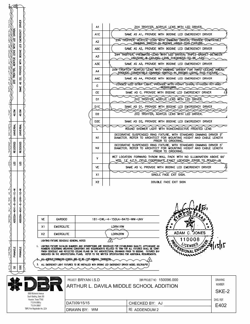

WEIGHT ROOME136
DPC
LJ1-28
LJ1-29
WPGFCI
WPGFCI
33
3
3
LJ1-47 LJ1-49
LJ1-48 LJ1-50
LJ1-51
STORAGEE136A
OFFICEE137
STORAGEE138
2
2
DRAWN BY:
PROJECT:
CHECKED BY:
DBR PROJECT NO:
DWG. REF.
DRAWING
NUMBER
DATE:
RE:
713.914.0888 p
713.914.0886 f
9990 Richmond Avenue
South Building, Suite 300
Houston, Texas 77042
BRYAN I.S.D
TBPE Firm Registration No. 2234 ADDENDUM 2
ARTHUR L. DAVILA MIDDLE SCHOOL ADDITION
150096.000
WM
09/15/15 AJ
SKE-3
EP212

1/2
M
K K
ELECT.J109
I.T.J110
HJ
LJ1
TLJ1
LJ1-18
2
LJ1-69 2
9
8
DRAWN BY:
PROJECT:
CHECKED BY:
DBR PROJECT NO:
DWG. REF.
DRAWING
NUMBER
DATE:
RE:
713.914.0888 p
713.914.0886 f
9990 Richmond Avenue
South Building, Suite 300
Houston, Texas 77042
BRYAN I.S.D
TBPE Firm Registration No. 2234 ADDENDUM 2
ARTHUR L. DAVILA MIDDLE SCHOOL ADDITION
150096.000
WM
09/15/15 AJ
SKE-4
EP213
CONNECT OVERHEAD MOTORIZED ROLLING DOOR AS SHOWN. COORDINATE EXACT LOCATION WITH ARCHITECT PRIOR TO ROUGH-IN. REFER TOMANUFACTURERS INSTALLATION INSTRUCTIONS.
KEYED SWITCHES PROVIDED WITH OVERHEAD DOOR. COORDINATE EXACT LOCATION WITH ARCHITECT PRIOR TO ROUGH-IN. REFER TOMANUFACTURER'S INSTALLATION INSTRUCTIONS
8
9

MENSJ121
WOMENSJ122
GFCI
GFCI
WPGFCI
LJ2-39
GFCI
GFCI
LJ2-44
7
2
2
10
UP
11
12
EXISTING LOWVOLTAGE CONDUITS
TO FOOTBALLSTADIUM
DRAWN BY:
PROJECT:
CHECKED BY:
DBR PROJECT NO:
DWG. REF.
DRAWING
NUMBER
DATE:
RE:
713.914.0888 p
713.914.0886 f
9990 Richmond Avenue
South Building, Suite 300
Houston, Texas 77042
BRYAN I.S.D
TBPE Firm Registration No. 2234 ADDENDUM 2
ARTHUR L. DAVILA MIDDLE SCHOOL ADDITION
150096.000
WM
09/15/15 AJ
SKE-5
EP213
APPROXIMATE LOCATION OF EXISTING FLUSH WITH GRADE PULLBOX FOR POWER FROM FOOTBALL FIELD PANEL "HS" SERVING PORTABLEBUILDINGS. SCOPE OF WORK TO INCLUDE DEMOLITION OF EXISITNG PULLBOX AND CONDUIT. REMOVE CONDUCTORS BACK TO EXISTING PANEL.REFER TO TECHNOLOGY DRAWINGS FOR SCOPE ADDITIONAL SCOPE OF WORK RELATED TO FIRE ALARM, COMMUNICATIONS, BAS, ETC.
PROVIDE NEW FLUSH WITH GRADE PULLBOX, SIZES TO MATCH EXISTING, TO INTERCEPT EXISTING LOW VOLTAGE CONDUITS FOR DAT, F/A, BAS,COMMUNITACTION, ETC. FIELD COORDINATE PLACEMENT WITH TH EXISTING CONDITIONS.
PROVIDE NEW CONDUITS QUANTITY AND SIZE TO MATCH EXISTING.
CONDUITS UP IN TO WALL TO ABOVE ACCESSIBLE CEILING. SEE TECHNOLOGY FOR CABLING INFORMATION.
7
10
11
12

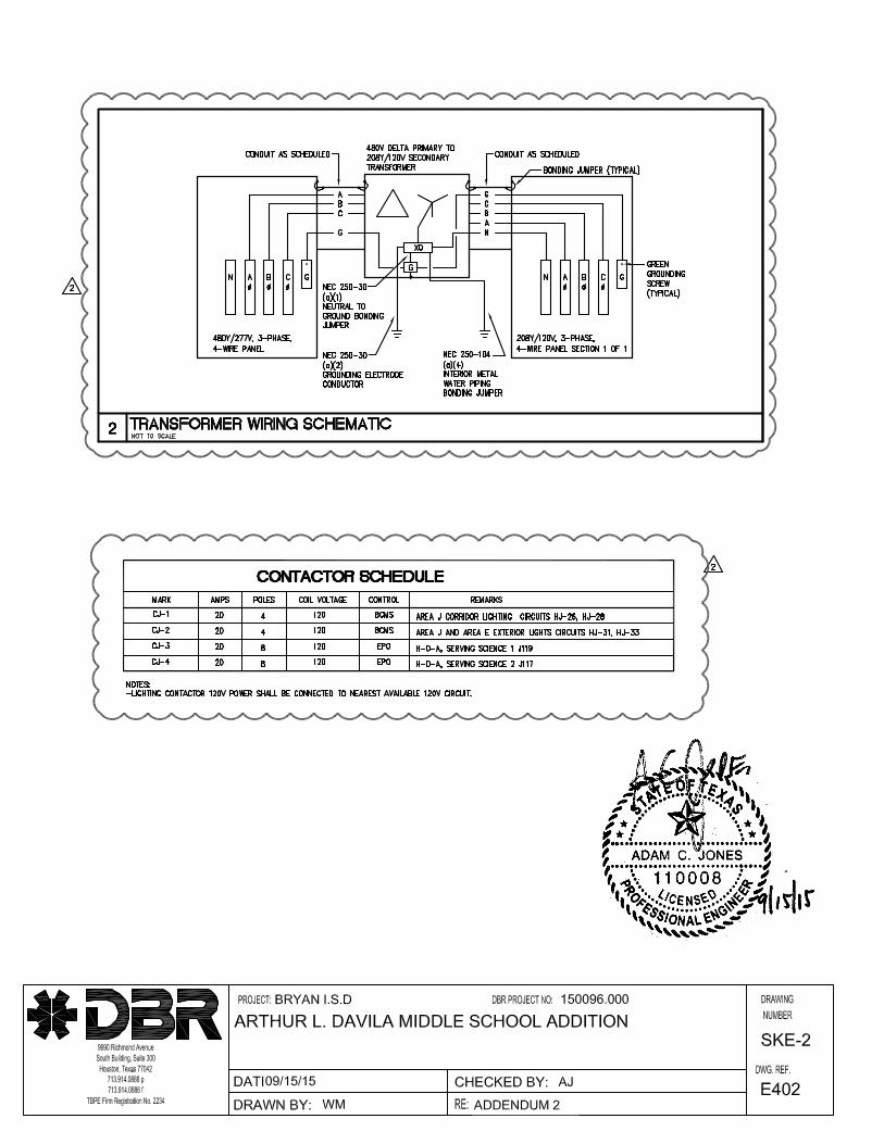
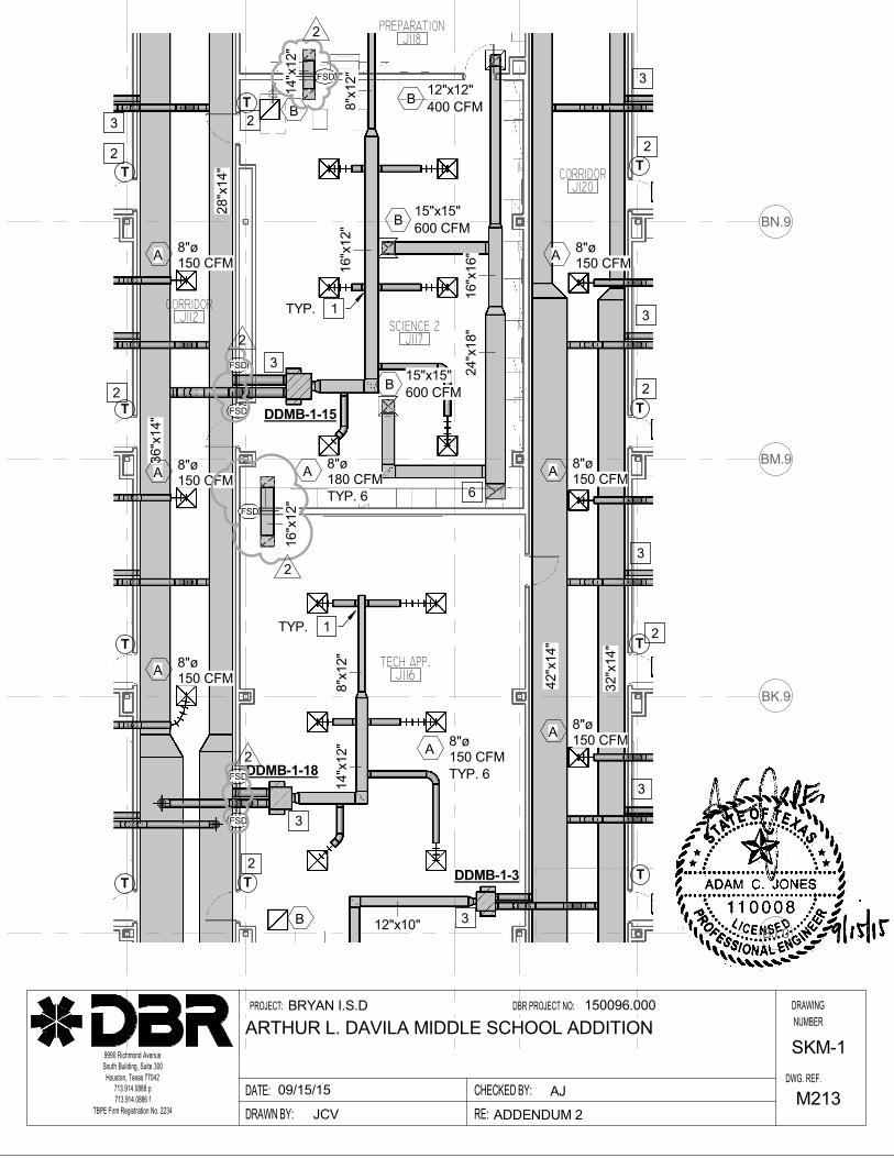
BJ.0
BK.9
BM.9
BN.9
TECH APP.J116
SCIENCE 2J117
CORRIDORJ112
CORRIDORJ120
PREPARATIONJ118
DDMB-1-18
DDMB-1-15
DDMB-1-3
16"x
12"
8"x
12"
36"x
14"
8"x
12"
14"x
12"
12"x10"
B
B
8"øA
150 CFM
TYP. 6
16"x
16"
24"x
18"
15"x15"B
600 CFM
8"øA
180 CFM
TYP. 6
15"x15"B
600 CFM
12"x12"B
400 CFM
T
T
T
TT
T
T
TT
T
42"x
14"
32"x
14"
28"x
14"
8"øA
150 CFM
8"øA
150 CFM
8"øA
150 CFM
8"øA
150 CFM
8"øA
150 CFM
8"øA
150 CFM
1TYP.
1TYP.
2
2
2
2
2
2
2
3
3
3
3
3
3
3
3
6
16"x
12"
14"x
12"
FSD
FSD
2
2
FSD
FSD
FSD
FSD
2
2
DRAWN BY:
PROJECT:
CHECKED BY:
DBR PROJECT NO:
DWG. REF.
DRAWING
NUMBER
DATE:
RE:
713.914.0888 p
713.914.0886 f
9990 Richmond Avenue
South Building, Suite 300
Houston, Texas 77042
BRYAN I.S.D
TBPE Firm Registration No. 2234 ADDENDUM 2
ARTHUR L. DAVILA MIDDLE SCHOOL ADDITION
150096.000
JCV
09/15/15 AJ
SKM-1
M213

76.1
BU
BV
71.3 75.472.1
BP.8
BT
74.9
SCIENCE 1J119
CORRIDORJ100
DDMB-1-9
DDMB-1-10
24"x
14"
18"x
14"
10"x
12"
16"x
12"
8"øA
175 CFM
8"øA
200 CFM
18"x
18"
B
15"x15"B
600 CFM
15"x15"15"x15"
B600 CFM
15"x15"
T
T
T
T
T
8"øA
150 CFM
8"øA
150 CFM
8"øA
150 CFM
1TYP.
1TYP.
2
2
2
2
3
3 3
6
8"x
12"
B
14"x
12"
14"x
12"
8"øA
180 CFM
TYP. 6
FSD
FSD
2
2
FSD
FSD
2
DRAWN BY:
PROJECT:
CHECKED BY:
DBR PROJECT NO:
DWG. REF.
DRAWING
NUMBER
DATE:
RE:
713.914.0888 p
713.914.0886 f
9990 Richmond Avenue
South Building, Suite 300
Houston, Texas 77042
BRYAN I.S.D
TBPE Firm Registration No. 2234 ADDENDUM 2
ARTHUR L. DAVILA MIDDLE SCHOOL ADDITION
150096.000
JCV
09/15/15 AJ
SKM-2
M213

B-1
NAT. GAS
CONDENSING
1,000
927
5:1
69.8
150/180
95%
10
4" DIA.
120/1/60
6.6
HYDROTHERM
KN-10
1,2,3,4
1.
2.
3.
4.
TURNDOWN RATIO
FLUE SIZE
MANUFACTURER
MODEL NUMBER
VOLTAGE/PHASE/FREQUENCY
FLA
BOILER SCHEDULE
OUTPUT MBH
GPM
EWT/LWT (°F)
MARK
MAX. PRESSURE DROP (FT. HD.)
THERMAL EFFICIENCY
FUEL
INPUT MBH
STYLE
NOTES
NOTES:
BOILER MUST MEET LATEST LOW NOx REQUIREMENTS FOR TEXAS.
BOILER SHALL BE SEQUENCED WITH AMBIENT OUTDOOR AIR TEMPERATURE RESET. RE:
2/M5-01 FOR HOT WATER SYSTEM CONTROL SCHEMATIC AND SEQUENCE OF OPERATION.
PROVIDE CATEGORY IV STAINLESS STEEL COMBUSTION EXHAUST VENT SIZED AS
INDICATED.
PROVIDE BOILER CONTROLLER WITH BACNET INTERFACE CARD FOR INTEGRATION WITH
EXISTING EMCS.

CR
CR
CR DC
DC
DC
DC
DR
CR
DC
DC
DC
DC
DC
DC
AP
CONFERENCEB120
OFFICEB122
RECEPTIONB105
WAITINGB104
PRINCIPAL
OFFICEB102
VESTIBULEB100
CORRIDORB101
ACS
ACS
D2
D2
D2
D2 D2
D2
W
AVI
AVO
D2
WM10'-0"
3
2
2
2
2
2
2
2
DRAWN BY:
PROJECT:
CHECKED BY:
DBR PROJECT NO:
DWG. REF.
DRAWING
NUMBER
DATE:
RE:
713.914.0888 p
713.914.0886 f
9990 Richmond Avenue
South Building, Suite 300
Houston, Texas 77042
BRYAN I.S.D
TBPE Firm Registration No. 2234 ADDENDUM 2
ARTHUR L. DAVILA MIDDLE SCHOOL ADDITION
150096.000
Marcus Alegria
09/15/15 James Ledbetter
SK-T-1
T211