bsd k -s uak / kak bsd pi s t o n sp e c fi ci a t oi n s ... · 1.1 bsd...
TRANSCRIPT

1.1 BSD Kolbenspeicher-Spezifikationen UAK/KAK 01-2008 1.1 BSD Piston Accumulator Specifications UAK/KAK 01-2008 1
BOLE
NZ
& SC
HÄ
FER
BSD KolBenSpeicher-SpezifiKationen UaK / KaK
BSD piSton accUmUlator SpecificationS UaK / KaK
2 1.1 BSD Kolbenspeicher-Spezifikationen UAK/KAK 01-2008 1.1 BSD Piston Accumulator Specifications UAK/KAK 01-2008
BOLE
NZ
& SC
HÄ
FER
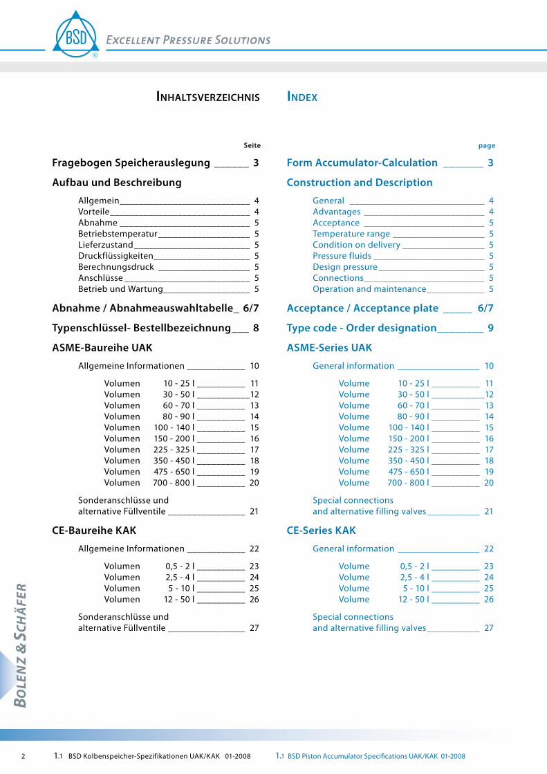
page
Form Accumulator-Calculation _______ 3
Construction and Description
General ____________________________ 4 Advantages _________________________ 4 Acceptance _________________________ 5 Temperature range ___________________ 5 Condition on delivery _________________ 5 Pressure fluids _______________________ 5 Design pressure ______________________ 5 Connections _________________________ 5 Operation and maintenance ____________ 5
Acceptance / Acceptance plate _____ 6/7
Type code - Order designation ________ 9
ASME-Series UAK
General information _________________ 10
Volume 10 - 25 l __________ 11 Volume 30 - 50 l ___________12 Volume 60 - 70 l __________ 13 Volume 80 - 90 l __________ 14 Volume 100 - 140 l __________ 15 Volume 150 - 200 l __________ 16 Volume 225 - 325 l __________ 17 Volume 350 - 450 l __________ 18 Volume 475 - 650 l __________ 19 Volume 700 - 800 l __________ 20
Special connections and alternative filling valves ___________ 21
CE-Series KAK
General information _________________ 22
Volume 0,5 - 2 l __________ 23 Volume 2,5 - 4 l __________ 24 Volume 5 - 10 l __________ 25 Volume 12 - 50 l __________ 26
Special connections and alternative filling valves ___________ 27
inDexinhaltSverzeichniS
Seite
Fragebogen Speicherauslegung ______ 3
Aufbau und Beschreibung
Allgemein ___________________________ 4 Vorteile _____________________________ 4 Abnahme ___________________________ 5 Betriebstemperatur ___________________ 5 Lieferzustand ________________________ 5 Druckflüssigkeiten____________________ 5 Berechnungsdruck ___________________ 5 Anschlüsse __________________________ 5 Betrieb und Wartung __________________ 5
Abnahme / Abnahmeauswahltabelle_ 6/7
Typenschlüssel- Bestellbezeichnung ___ 8
ASME-Baureihe UAK
Allgemeine Informationen ____________ 10
Volumen 10 - 25 l __________ 11 Volumen 30 - 50 l ___________12 Volumen 60 - 70 l __________ 13 Volumen 80 - 90 l __________ 14 Volumen 100 - 140 l __________ 15 Volumen 150 - 200 l __________ 16 Volumen 225 - 325 l __________ 17 Volumen 350 - 450 l __________ 18 Volumen 475 - 650 l __________ 19 Volumen 700 - 800 l __________ 20
Sonderanschlüsse und alternative Füllventile ________________ 21
CE-Baureihe KAK
Allgemeine Informationen ____________ 22
Volumen 0,5 - 2 l __________ 23 Volumen 2,5 - 4 l __________ 24 Volumen 5 - 10 l __________ 25 Volumen 12 - 50 l __________ 26
Sonderanschlüsse und alternative Füllventile ________________ 27
1.1 BSD Kolbenspeicher-Spezifikationen UAK/KAK 01-2008 1.1 BSD Piston Accumulator Specifications UAK/KAK 01-2008 3
BOLE
NZ
& SC
HÄ
FER
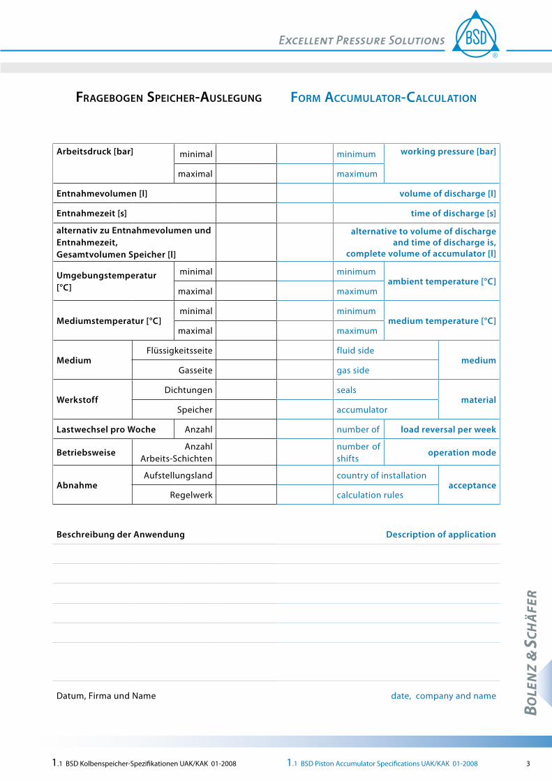
form accUmUlator-calcUlationfrageBogen Speicher-aUSlegUng
Arbeitsdruck [bar] minimal minimum working pressure [bar]
maximal maximum
Entnahmevolumen [l] volume of discharge [l]
Entnahmezeit [s] time of discharge [s]
alternativ zu Entnahmevolumen und Entnahmezeit, Gesamtvolumen Speicher [l]
alternative to volume of discharge and time of discharge is,
complete volume of accumulator [l]
Umgebungstemperatur [°C]
minimal minimumambient temperature [°C]
maximal maximum
Mediumstemperatur [°C]minimal minimum
medium temperature [°C]maximal maximum
MediumFlüssigkeitsseite fluid side
mediumGasseite gas side
WerkstoffDichtungen seals
materialSpeicher accumulator
Lastwechsel pro Woche Anzahl number of load reversal per week
BetriebsweiseAnzahl
Arbeits-Schichtennumber of shifts
operation mode
AbnahmeAufstellungsland country of installation
acceptanceRegelwerk calculation rules
Beschreibung der Anwendung Description of application
Datum, Firma und Name date, company and name
4 1.1 BSD Kolbenspeicher-Spezifikationen UAK/KAK 01-2008 1.1 BSD Piston Accumulator Specifications UAK/KAK 01-2008
BOLE
NZ
& SC
HÄ
FER
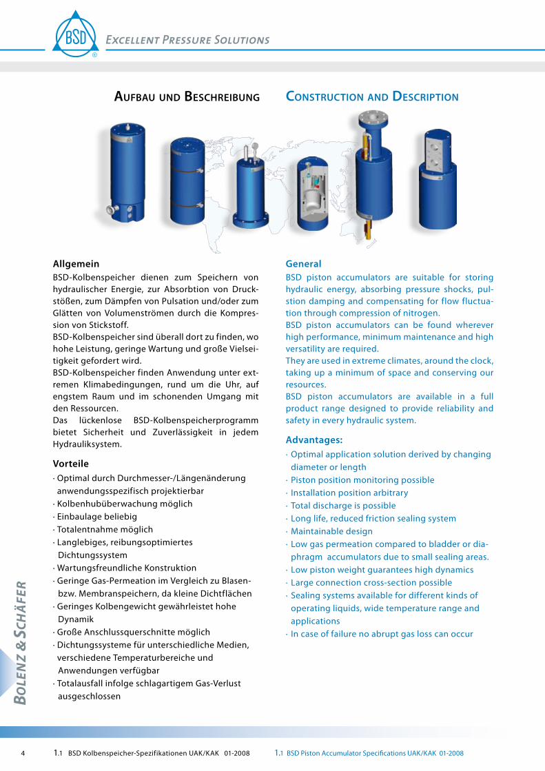
conStrUction anD DeScription
GeneralBSD piston accumulators are suitable for storing hydraulic energy, absorbing pressure shocks, pul-stion damping and compensating for flow fluctua-tion through compression of nitrogen.BSD piston accumulators can be found wherever high performance, minimum maintenance and high versatility are required.They are used in extreme climates, around the clock, taking up a minimum of space and conserving our resources.BSD piston accumulators are available in a full product range designed to provide reliability and safety in every hydraulic system.
Advantages:· Optimal application solution derived by changing diameter or length· Piston position monitoring possible· Installation position arbitrary· Total discharge is possible· Long life, reduced friction sealing system· Maintainable design· Low gas permeation compared to bladder or dia-
phragm accumulators due to small sealing areas.· Low piston weight guarantees high dynamics· Large connection cross-section possible· Sealing systems available for different kinds of
operating liquids, wide temperature range and applications
· In case of failure no abrupt gas loss can occur
aUfBaU UnD BeSchreiBUng
AllgemeinBSD-Kolbenspeicher dienen zum Speichern von hydraulischer Energie, zur Absorbtion von Druck-stößen, zum Dämpfen von Pulsation und/oder zum Glätten von Volumenströmen durch die Kompres-sion von Stickstoff.BSD-Kolbenspeicher sind überall dort zu finden, wo hohe Leistung, geringe Wartung und große Vielsei-tigkeit gefordert wird.BSD-Kolbenspeicher finden Anwendung unter ext-remen Klimabedingungen, rund um die Uhr, auf engstem Raum und im schonenden Umgang mit den Ressourcen.Das lückenlose BSD-Kolbenspeicherprogramm bietet Sicherheit und Zuverlässigkeit in jedem Hydrauliksystem.
Vorteile· Optimal durch Durchmesser-/Längenänderung anwendungsspezifisch projektierbar· Kolbenhubüberwachung möglich· Einbaulage beliebig· Totalentnahme möglich· Langlebiges, reibungsoptimiertes
Dichtungssystem· Wartungsfreundliche Konstruktion· Geringe Gas-Permeation im Vergleich zu Blasen-
bzw. Membranspeichern, da kleine Dichtflächen· Geringes Kolbengewicht gewährleistet hohe
Dynamik· Große Anschlussquerschnitte möglich· Dichtungssysteme für unterschiedliche Medien, verschiedene Temperaturbereiche und
Anwendungen verfügbar· Totalausfall infolge schlagartigem Gas-Verlust
ausgeschlossen

1.1 BSD Kolbenspeicher-Spezifikationen UAK/KAK 01-2008 1.1 BSD Piston Accumulator Specifications UAK/KAK 01-2008 5
BOLE
NZ
& SC
HÄ
FER
Temperature rangeTemperature range standard -10° C to +80° C,different temperature ranges, e.g. -40° C to +80° C on request.
Condition on deliveryBase-coated with universal priming colour RAL 1001 (beige) inside and connecting surface oiled and openings protected, without hydr. fluids, without gas filling.Other colors and sand blasting or other surface treatments (e.g. galvanic zinc plating) is possible. Please ask for our offer.
Pressure FluidsSealing type PUR:mineral oil, hydraulic oil due to DIN 51524 part 2Sealing type NBR:hydraulic oil due to DIN 51524 part 2, flame protected liquids, water and emulsions, but no HFD-fluids.BSD piston accumulators for other tempera-tures, other fluids or with longterm protection on request.
Design pressure (see selection data sheet)The design pressure corresponds with the max. allowable working pressure (MAWP) and is also the max. permissible set pressure for the safety equip-ment (safety valves, burst-discs) against pressure excess. We recommend operation of the accumulators with a maximum pressure of up to 0,9 x MAWP to avoid safety equipment repetitive response.
ConnectionsBSD piston accumulators are also available with other or additional connections (e.g. acc. to works standards).Larger nominal widths (for high flow rates see pecial connections / alternative filling valves) can be pro-vided by special design. Let us know the required dimension and we ‘ll make a proposal.
Operating and maintenancePlease see the notes in the operating and mainte-nance instruction section.
BetriebstemperaturTemperaturbereich Standard: -10° C bis +80° C,abweichende Temperaturbereiche, z.B. -40° C bis +80° C, auf Anfrage möglich.
LieferzustandGrundiert mit Universal-Haftgrund RAL 1001 (beige), innen ölbenetzt, Anschlussfläche blank, befettet und Öffnungen geschützt, ohne Ölfüllung, ohne Gasfüllung.Andere Farbbehandlungen, Strahlen oder sonstige Oberflächenbeschichtungen (z.B. galvanisch ver-zinkt) sind möglich. Fordern Sie unsere Angebote an!
Druck-FlüssigkeitenDichtungs-Ausführung PUR:Mineralöle, Hydrauliköle nach DIN 51524, Teil 2,Dichtungs-Ausführung NBR:Hydrauliköle nach DIN 51524, Teil 2, schwer entflammbare Flüssigkeiten, Wasser und Emulsionen, außer HFD-FlüssigkeitenBSD-Kolbenspeicher für andere Temperaturen, andere Fluide oder mit Langzeitkonservierung auf Anfrage.
Berechnungsdruck (siehe Auswahltabelle)Der Berechnungsdruck entspricht dem maximal zulässigen Betriebsüberdruck (MAWP) und ist gleichzeitig der maximale Einstelldruck von Sicher-heitseinrichtungen gegen Drucküberschreitung (Sicherheitsventile, Berstscheiben).Wir empfehlen, die Speicher mit max. 0,9 x MAWP zu betreiben, um ein Ansprechen der Sicherheits-einrichtungen zu vermeiden.
AnschlüsseBSD-Kolbenspeicher sind auch mit anderen bzw. zusätzlichen Anschlüssen (z.B. nach Werksnormen) erhältlich. Durch Sonderkonstruktionen sind auch durchaus erheblich größere Nennweiten möglich (für große Volumenströme siehe Sonderanschlüsse / alter-native Füllventile). Teilen Sie uns die gewünschte Nennweite mit. Wir machen Ihnen einen Vorschlag!
Betrieb und WartungBitte beachten Sie hierzu die Hinweise in der Betriebs- und Wartungsanweisung.

6 1.1 BSD Kolbenspeicher-Spezifikationen UAK/KAK 01-2008 1.1 BSD Piston Accumulator Specifications UAK/KAK 01-2008
BOLE
NZ
& SC
HÄ
FER
BOLENZ & SCHÄFER accumulator systems are manu-factured for the European market and are approved in accordance with the Pressure Equipment Direc-tive PED 97/23/EC applicable as from 29.11.1999 and binding since 30.05.2002. This is applicable to the KAK and AK series piston accumulators.
Approval is by way of individual approval, normally by the TÜV [Technical Monitoring Association] as the appointed laboratory. The accumulator systems are awarded a CE mark and are supplied with a decla-ration of conformity and operating instructions. In addition, the standard documentation comprises a certificate of conformity by the appointed labora-tory, an acceptance drawing and a list of materials used. This also guarantees possible reworking or overhauling of the individual components after decades of use.
This Pressure Equipment Directive is also accepted by many other countries besides the direct EU member states. Only some additional approval doc-umentation may sometimes be required. Countries such as Russia or China in addition require certifica-tion of the manufacturer in accordance with the leg-islation of the specific exporting country. BOLENZ & SCHÄFER possesses the most important certifica-tions and is therefore in a position to supply out-standing and top quality accumulator technology worldwide.
In addition to the Pressure Equipment Directive, the ASME Code in the USA is another globally signifi-cant regulation. BOLENZ & SCHÄFER was awarded the ASME U-Stamp in 1981, authorising the com-pany to design and produce accumulators in accord-ance with American regulations. We thus have the longest experience as a German piston accumulator manufacturer with these regulations.
The scope of the ASME Code only covers pressure vessels and accumulators with an inside diameter greater than 6 inches, however. This means that with an accumulator diameter of less than 6 inches the CE series KAK may be applied.
The ASME Code is also accepted in other countries such as Canada, for instance. However, province-dependent certification is in addition required in Canada.
acceptanceaBnahme
BOLENZ & SCHÄFER Speichersysteme werden für den europäischen Markt nach "Druckgerätericht-linie DGRL 97/23/EG" hergestellt und abgenommen. Dies gilt für die Kolbenspeicher-Baureihen KAK und AK.
Die Abnahme erfolgt meist als Einzelabnahme gemäß Modul G durch den TÜV als benannte Stelle. Die Speichersysteme sind mit CE-Kennzeichen versehen und werden mit einer Konformitätserklärung und einer entsprechenden Betriebsanleitung geliefert. Darüber hinaus besteht die Abnahme-Dokumenta-tion zusätzlich aus einer Konformitätsbescheinigung der benannten Stelle, einer Abnahmezeichnung und einer Auflistung der verwendeten Werkstoffe. Dadurch ist auch nach jahrzehntelangem Betrieb eine Überarbeitung oder Instandsetzung von ein-zelnen Bauteilen gewährleistet.
Die Druckgeräterichtlinie wird neben den EU-Mit-gliedsstaaten auch von vielen anderen Ländern akzeptiert. Zum Teil ist nur eine zusätzliche Abnah-medokumentation erforderlich. Länder, wie z.B. Russland, Ukraine oder China verlangen zusätzlich eine Zulassung des Herstellers.
Druckbehälterlieferungen in die USA müssen dem amerikanischen Regelwerk, dem ASME Code, ent-sprechen. BOLENZ & SCHÄFER besitzt seit 1981 die Zulassung, nach ASME Code Section VIII Division 1, zu liefern und hat damit als Kolbenspeicherhersteller in Deutschland die längste Erfahrung mit diesem Regelwerk. Behälter mit ASME-Abnahme werden mit dem sogenannten "U-Stamp" gekennzeichnet und mit einem Data-Report als Abnahmedokumen-tation geliefert.
Behälter nach ASME-Code werden auch in Canada akzeptiert. In Canada ist eine zusätzliche Geneh-migung (Canadian Registration Number, CRN) der jeweiligen Provinz erforderlich, in die geliefert werden soll. Die Provinz bzw. der Aufstellungsort muss bei der Bestellung angegeben werden. Die ASME Abnahme wird häufig auch im Bereich "Off-shore" oder in Teilen Asiens gefordert.
Unter den Geltungsbereich des ASME-Codes fallen jedoch nur Druckbehälter und Speicher mit einem Innendurchmesser größer 6 Zoll. Bei Speicherdurch-messer kleiner 6 Zoll kann die CE-Baureihe KAK ein-gesetzt werden.

1.1 BSD Kolbenspeicher-Spezifikationen UAK/KAK 01-2008 1.1 BSD Piston Accumulator Specifications UAK/KAK 01-2008 7
BOLE
NZ
& SC
HÄ
FER
Over and above this, BOLENZ & SCHÄFER is accred-ited for all required product and company certifica-tions worldwide. The tables below list a selection of the most important approvals. Should your envis-aged country of application or required approval not be included, please provide us with full details in your request.
Acceptance selection tableAcceptance variations based on the KAK / AK series with CE acceptance:
Acceptance variations based on UAK series with ASME U-stamp acceptance:
Refer to the Chapter or the "AcceptAnce" brochure for further information and details on acceptance, com-missioning and regular tests.
BOLENZ & SCHÄFER verfügt über alle wichtigen Produkt- und Unternehmenszulassungen weltweit. Die nachfolgenden Tabellen enthalten eine Auswahl der gebräuchlichsten Abnahmevarianten. Sollte Ihr geplantes Aufstellungsland oder die gewünschte Abnahme nicht dabei sein, geben Sie dieses bitte bei der Anfrage im Klartext an.
Abnahmen-AuswahltabelleAbnahmevarianten basierend auf Baureihe KAK / AK mit CE Abnahme:
LDKZ Länder Abnahmevorschrift: Var. Nr.
Approval regulation Countries Country-code
EU EU-Mit-glieds-staaten
DGRL 97/23/EG (Druck-Geräte-Richtlinie)mit CE-Kennzeichnung
50 PED 97/23/EC [Pressure Equipment Directive] with CE mark
EU member states
EU
AUS Australien Australian Standard 1210 Supplement 1, Cl. 1 H
14 Australian Standard 1210 Supplement 1, Cl. 1 H
Australia AUS
CH Schweiz DGRL 97/23/EG + SVTI 502 PED 97/23/EC + SVTI Switzer-land
CH
KOR Korea DGRL 97/23/EG + ESCO 60 PED 97/23/EC + ESCO Korea KOR
MAL Malaysia DGRL 97/23/EG + DOSH 61 PED 97/23/EC + DOSH Malaysia MAL
N Norwegen DGRL 97/23/EG + DNV 509 PED 97/23/EC + DNV Norway N
RUS Russland DGRL 97/23/EG + GOST 520 PED 97/23/EC + GOST Russia RUS
UKR Ukraine DGRL 97/23/EG + Ukr SEPRO 522 PED 97/23/EC + Ukr SEPRO Ukraine UKR
VRC China DGRL 97/23/EG + ML 534 PED 97/23/EC + ML China VRC
Abnahmevarianten basierend auf Baureihe UAK mit ASME U-Stamp Abnahme:
LDKZ Länder Abnahmevorschrift: Var. Nr.
Approval regulation Countries Country-code
USA USA ASME Code Sect. VIII Div. 1 15 ASME Code Sect. VIII Div. 1 USA USA
CND Kanada ASME Code + CRN (Canadian Registration No.)Zulassung provinzabhängig – Provinz angeben
29 ASME Code + CRN (Canadian Registration No.)Certification province- dependent – name province
Canada CND
J Japan ASME Code + M.E.T.I. Japan Baureihe UAK mit modifizier-ten Abmessungen.
30 ASME Code + M.E.T.I. Japan UAK series with modified dimensions.
Japan J
Weitere Informationen und Details zum Thema Abnahme, Inbetriebnahme und wiederkeh-rende Prüfungen finden Sie im Kapitel bzw. in der Broschüre "AbnAhme".
8 1.1 BSD Kolbenspeicher-Spezifikationen UAK/KAK 01-2008 1.1 BSD Piston Accumulator Specifications UAK/KAK 01-2008
BOLE
NZ
& SC
HÄ
FER
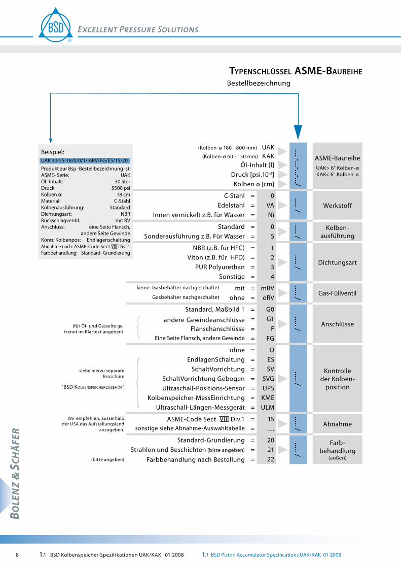
typenSchlüSSel aSme-BaUreihe Bestellbezeichnung
(Kolben-ø 180 - 800 mm) UAK (Kolben-ø 60 - 150 mm) KAK
.... -...-...-.../
ASME-Baureihe UAK> 6" Kolben-ø KAK< 6" Kolben-ø
Öl-Inhalt [l] Druck [psi.10-2]Kolben ø [cm]
C-Stahl = 0 ..... / WerkstoffEdelstahl = VAInnen vernickelt z.B. für Wasser = Ni
Standard = 0
..... /
Kolben-ausführungSonderausführung z.B. Für Wasser = S
NBR (z.B. für HFC) = 1
..... / DichtungsartViton (z.B. für HFD) = 2
PUR Polyurethan = 3Sonstige = 4
keine Gasbehälter nachgeschaltet mit = mRV
..... / Gas-FüllventilGasbehälter nachgeschaltet ohne = oRV
Standard, Maßbild 1 = G0
..... / Anschlüsse(für Öl- und Gasseite ge- trennt im Klartext angeben)
andere Gewindeanschlüsse = G1Flanschanschlüsse = F
Eine Seite Flansch, andere Gewinde = FG
siehe hierzu separate Broschüre
"bSD KolbenSpeicherzubehör"
ohne = O
..... /
Kontrolle der Kolben-
position
EndlagenSchaltung = ESSchaltVorrichtung = SV
SchaltVorrichtung Gebogen = SVGUltraschall-Positions-Sensor = UPS
Kolbenspeicher-MessEinrichtung = KMEUltraschall-Längen-Messgerät = ULM
Wir empfehlen, ausserhalb der USA das Aufstellungsland
anzugeben.
ASME-Code Sect. Div.1 = 15
..... / Abnahmesonstige siehe Abnahme-Auswahltabelle = ....
Standard-Grundierung = 20 ..... /
Farb-behandlung
(außen)Strahlen und Beschichten (bitte angeben) = 21
(bitte angeben) Farbbehandlung nach Bestellung = 22
Beispiel:UAK 30-55-18/0/0/1/mRV/FG/ES/15/20Produkt zur Bsp.-Bestellbezeichnung ist:ASME- Serie: UAKÖl- Inhalt: 30 literDruck: 5500 psiKolben ø: 18 cmMaterial: C-StahlKolbenausführung: StandardDichtungsart: NBRRückschlagventil: mit RVAnschluss: eine Seite Flansch, andere Seite GewindeKontr. Kolbenpos: EndlagenschaltungAbnahme nach: ASME-Code Sect. Div. 1Farbbehandlung: Standard -Grundierung

1.1 BSD Kolbenspeicher-Spezifikationen UAK/KAK 01-2008 1.1 BSD Piston Accumulator Specifications UAK/KAK 01-2008 9
BOLE
NZ
& SC
HÄ
FER
type coDe aSme-SerieS
Order designation
ASME-Series UAK > 6" Piston -ø KAK < 6" Piston-ø
.... -...-...-.../
UAK (piston-ø 180 - 800 mm) KAK (piston-ø 60 - 150 mm)
oil capacity [l]pressure [psi.10-2]piston ø [cm]
material
..... /
0VANi
= carbon steel= stainless steel= nickel-plated, e.g. for water
design of piston
..... /
0 = standardS = special design, e.g. for water
type of seals
..... /
1 = NBR (e.g. for HFC)2 = Viton (e.g. for HFD)3 = polyurethane4 = Others
Gas filling valve
.... /mRV = with no pressure vessel adapted
o RV = without pressure vessel are adapted
connections
..... /G0 = standard, figure no. 1G1 = other thread connections
(to be indicated for gas and oil separately)F = flange connections
FG = flange one side, thread the other
monitoring of the piston
position
..... /
O = without
see for this separate brochure
"bSD piSton AccumulAtor equipment"
ES = limit switching deviceSV = switching deviceSVG = switching device bendedUPS = ultrasonic position sensorKME = piston accumulator measuringULM = ultrasonic length messuring device
acceptance
..... /
15 = ASME-code Sect. Div. 1 We recommend, outside the EU-members, to indicate the name of the country where the accumulator will be installed
.... = others see also acceptance selection
paintings (outside)
..... /
20 = standard primer21 = sand blasting and coating (please specify)
22 = painting on demand (please specify)
Example:UAK 30-55-18/0/0/1/mRV/FG/ES/15/20Product of order designation (e.g) is:ASME-Series: UAKoil-capacity: 30 literpressure: 5500 psipiston ø: 18 cmmaterial: carbon steeldesign of piston: standardtype of seals: NBRgas non return valve: with RVconnection: flange one side, other thread monitor. piston pos.: limit switching deviceacceptance by: ASME-code Sect. Div. 1painting (outside): standard primer

10 1.1 BSD Kolbenspeicher-Spezifikationen UAK/KAK 01-2008 1.1 BSD Piston Accumulator Specifications UAK/KAK 01-2008
BOLE
NZ
& SC
HÄ
FER
aSme-SerieS UaKaSme-BaUreihe UaK
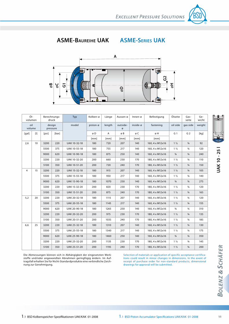
Volume: 2,6 bis 211 gal respectively 10 to 1500 lDesign pressure: 3200 to 9000 psirespectively 220 to 620 bar Piston-ø: 180 to 800 mmApproval: ASME-Code Sect. Div.1
ASME-Series UAK with screwed end caps
Pos. designation
1 tube
2 piston with seals
3 end cap oil side
4 end cap gas side
5 thread ring
6 end cap seal
7 BSD-gas-fill-valve
8 screw plug
Volumen: 10 bis 1500 l bzw. 2,6 bis 211 gal
Berechnungsdruck: 220 bis 620 bar bzw. 3200 bis 9000 psi
Kolben-ø: 180 bis 800 mmAbnahme: ASME-Code Sect. Div.1
84125 3 56 67
ASME-Baureihe UAK mit Gewinderingen
Pos. Bezeichnung
1 Zylinderrohr
2 Kolben mit Dichtungen
3 Einfüllstutzen Ölseite
4 Einfüllstutzen Gasseite
5 Gewindering
6 Stutzendichtung
7 BSD-Gas-Füllventil
8 Verschlußschraube
1.1 BSD Kolbenspeicher-Spezifikationen UAK/KAK 01-2008 1.1 BSD Piston Accumulator Specifications UAK/KAK 01-2008 11
BOLE
NZ
& SC
HÄ
FER
aSme-SerieS UaKaSme-BaUreihe UaK
UA
K 10
- 25
l
AøB G
1
G2
øH
øD
øC
Öl- volumen
Berechnungs-druck
Typ Kolben-ø Länge Aussen-ø Innen-ø Befestigung Ölseite Gas-seite
Ge-wicht
oil volume
design pressure
model piston-ø length outside-ø
inside-ø fastening oil side gas side weight
[gal] [l] [psi] [bar] ø D A ø B ø C ø H G 1 G 2 [kg]
[mm] [mm] [mm] [mm] [mm]
2,6 10 3200 220 UAK 10-32-18 180 720 207 140 160, 4 x M12x16 1 ½ ¾ 92
5500 375 UAK 10-55-18 180 755 217 140 160, 4 x M12x16 1 ½ ¾ 120
9000 620 UAK 10-90-18 180 875 250 140 160, 4 x M12x16 ¾ ¾ 240
3200 220 UAK 10-32-20 200 660 230 170 180, 4 x M12x16 1 ½ ¾ 110
5100 350 UAK 10-51-20 200 720 240 170 180, 4 x M12x16 1 ½ ¾ 150
4 15 3200 220 UAK 15-32-18 180 915 207 140 160, 4 x M12x16 1 ½ ¾ 105
5500 375 UAK 15-55-18 180 950 217 140 160, 4 x M12x16 1 ½ ¾ 140
9000 620 UAK 15-90-18 180 1070 250 140 160, 4 x M12x16 ¾ ¾ 275
3200 220 UAK 15-32-20 200 820 230 170 180, 4 x M12x16 1 ½ ¾ 120
5100 350 UAK 15-51-20 200 875 240 170 180, 4 x M12x16 1 ½ ¾ 165
5,2 20 3200 220 UAK 20-32-18 180 1115 207 140 160, 4 x M12x16 1 ½ ¾ 120
5500 375 UAK 20-55-18 180 1145 217 140 160, 4 x M12x16 1 ½ ¾ 155
9000 620 UAK 20-90-18 180 1265 250 140 160, 4 x M12x16 ¾ ¾ 310
3200 220 UAK 20-32-20 200 975 230 170 180, 4 x M12x16 1 ½ ¾ 135
5100 350 UAK 20-51-20 200 1035 240 170 180, 4 x M12x16 1 ½ ¾ 185
6,6 25 3200 220 UAK 25-32-18 180 1310 207 140 160, 4 x M12x16 1 ½ ¾ 130
5500 375 UAK 25-55-18 180 1340 217 140 160, 4 x M12x16 1 ½ ¾ 175
9000 620 UAK 25-90-18 180 1460 250 140 160, 4 x M12x16 ¾ ¾ 350
3200 220 UAK 25-32-20 200 1135 230 170 180, 4 x M12x16 1 ½ ¾ 145
5100 350 UAK 25-51-20 200 1195 240 170 180, 4 x M12x16 1 ½ ¾ 200
Die Abmessungen können sich in Abhängigkeit der eingesetzten Werk-stoffe und/oder angewandten Abnahmen geringfügig ändern. Im Auf-tragsfall erhalten Sie für Nicht-Standardprodukte eine verbindliche Zeich-nung zur Genehmigung.
Selection of materials or application of specific acceptance certifica-tions could result in minor changes in dimensions. In the event of receipt of purchase order for non-standard products, dimensional drawings for approval will be submitted.

12 1.1 BSD Kolbenspeicher-Spezifikationen UAK/KAK 01-2008 1.1 BSD Piston Accumulator Specifications UAK/KAK 01-2008
BOLE
NZ
& SC
HÄ
FER
aSme-SerieS UaKaSme-BaUreihe UaK
UA
K 30
- 50
l
AøB G
1
G2
øH
øD
øC
Öl- volumen
Berechnungs-druck
Typ Kolben-ø Länge Aussen-ø Innen-ø Befestigung Ölseite Gas-seite
Ge-wicht
oil volume
design pressure
model piston-ø length outside-ø
inside-ø fastening oil side gas side weight
[gal] [l] [psi] [bar] ø D A ø B ø C ø H G 1 G 2 [kg]
[mm] [mm] [mm] [mm] [mm]
7,9 30 3200 220 UAK 30-32-18 180 1505 207 140 160, 4 x M12x16 1 ½ ¾ 145
5500 375 UAK 30-55-18 180 1540 217 140 160, 4 x M12x16 1 ½ ¾ 190
9000 620 UAK 30-90-18 180 1660 250 140 160, 4 x M12x16 ¾ ¾ 390
3200 220 UAK 30-32-20 200 1295 230 170 180, 4 x M12x16 1 ½ ¾ 160
5100 350 UAK 30-51-20 200 1355 240 170 180, 4 x M12x16 1 ½ ¾ 220
3200 220 UAK 30-32-25 250 1030 290 220 240, 4 x M12x20 1 ½ ¾ 290
5100 350 UAK 30-51-25 250 1080 310 220 240, 4 x M12x20 1 ½ ¾ 410
10,6 40 3200 220 UAK 40-32-18 180 1900 207 140 160, 4 x M12x16 1 ½ ¾ 170
5500 375 UAK 40-55-18 180 1930 217 140 160, 4 x M12x16 1 ½ ¾ 230
9000 620 UAK 40-90-18 180 2050 250 140 220, 4 x M12x16 ¾ ¾ 460
3200 220 UAK 40-32-20 200 1615 230 170 180, 4 x M12x16 1 ½ ¾ 185
5100 350 UAK 40-51-20 200 1675 240 170 180, 4 x M12x16 1 ½ ¾ 255
3200 220 UAK 40-32-25 250 1235 290 220 240, 4 x M12x20 1 ½ ¾ 320
5100 350 UAK 40-51-25 250 1285 310 220 240, 4 x M12x20 1 ½ ¾ 450
13,2 50 3200 220 UAK 50-32-18 180 2295 207 140 160, 4 x M12x16 1 ½ ¾ 195
5500 375 UAK 50-55-18 180 2325 217 140 160, 4 x M12x16 1 ½ ¾ 265
9000 620 UAK 50-90-18 180 2445 250 140 160, 4 x M12x16 ¾ ¾ 535
3200 220 UAK 50-32-20 200 1930 230 170 180, 4 x M12x16 1 ½ ¾ 210
5100 350 UAK 50-51-20 200 1990 240 170 180, 4 x M12x16 1 ½ ¾ 290
3200 220 UAK 50-32-25 250 1440 290 220 240, 4 x M12x20 1 ½ ¾ 345
5100 350 UAK 50-51-25 250 1490 310 220 240, 4 x M12x20 1 ½ ¾ 495
Die Abmessungen können sich in Abhängigkeit der eingesetzten Werk-stoffe und/oder angewandten Abnahmen geringfügig ändern. Im Auf-tragsfall erhalten Sie für Nicht-Standardprodukte eine verbindliche Zeich-nung zur Genehmigung.
Selection of materials or application of specific acceptance certifica-tions could result in minor changes in dimensions. In the event of receipt of purchase order for non-standard products, dimensional drawings for approval will be submitted.

1.1 BSD Kolbenspeicher-Spezifikationen UAK/KAK 01-2008 1.1 BSD Piston Accumulator Specifications UAK/KAK 01-2008 13
BOLE
NZ
& SC
HÄ
FER
aSme-SerieS UaKaSme-BaUreihe UaK
UA
K 60
- 70
l
AøB G
1
G2
øH
øD
øC
Öl- volumen
Berechnungs-druck
Typ Kolben-ø Länge Aussen-ø Innen-ø Befestigung Ölseite Gas-seite
Ge-wicht
oil volume
design pressure
model piston-ø length outside-ø
inside-ø fastening oil side gas side weight
[gal] [l] [psi] [bar] ø D A ø B ø C ø H G 1 G 2 [kg]
[mm] [mm] [mm] [mm] [mm]
15,9 60 3200 220 UAK 60-32-18 180 2685 207 140 160, 4 x M12x16 1 ½ ¾ 220
5500 375 UAK 60-55-18 180 2720 217 140 160, 4 x M12x16 1 ½ ¾ 300
9000 620 UAK 60-90-18 180 2840 250 140 160, 4 x M12x16 ¾ ¾ 605
3200 220 UAK 60-32-20 200 2250 230 170 180, 4 x M12x16 1 ½ ¾ 235
5100 350 UAK 60-51-20 200 2310 240 170 180, 4 x M12x16 1 ½ ¾ 325
3200 220 UAK 60-32-25 250 1640 290 220 240, 4 x M12x20 1 ½ ¾ 370
5100 350 UAK 60-51-25 250 1690 310 220 240, 4 x M12x20 1 ½ ¾ 535
18,5 70 3200 220 UAK 70-32-18 180 3080 207 140 160, 4 x M12x16 1 ½ ¾ 245
5500 375 UAK 70-55-18 180 3110 217 140 160, 4 x M12x16 1 ½ ¾ 335
9000 620 UAK 70-90-18 180 3230 250 140 160, 4 x M12x16 ¾ ¾ 680
3200 220 UAK 70-32-20 200 2570 230 170 180, 4 x M12x16 1 ½ ¾ 260
5100 350 UAK 70-51-20 200 2630 240 170 180, 4 x M12x16 1 ½ ¾ 355
3200 220 UAK 70-32-25 250 1845 290 220 240, 4 x M12x20 1 ½ ¾ 400
5100 350 UAK 70-51-25 250 1895 310 220 240, 4 x M12x20 1 ½ ¾ 580
3200 220 UAK 70-32-31 310 1455 360 260 180, 4 x M12x16 1 ½ ¾ 515
5100 350 UAK 70-51-31 310 1565 370 260 180, 4 x M12x16 1 ½ ¾ 675
Die Abmessungen können sich in Abhängigkeit der eingesetzten Werk-stoffe und/oder angewandten Abnahmen geringfügig ändern. Im Auf-tragsfall erhalten Sie für Nicht-Standardprodukte eine verbindliche Zeich-nung zur Genehmigung.
Selection of materials or application of specific acceptance certifica-tions could result in minor changes in dimensions. In the event of receipt of purchase order for non-standard products, dimensional drawings for approval will be submitted.

14 1.1 BSD Kolbenspeicher-Spezifikationen UAK/KAK 01-2008 1.1 BSD Piston Accumulator Specifications UAK/KAK 01-2008
BOLE
NZ
& SC
HÄ
FER
aSme-SerieS UaKaSme-BaUreihe UaK
UA
K 80
- 90
l
AøB G
1
G2
øH
øD
øC
Öl- volumen
Berechnungs-druck
Typ Kolben-ø Länge Aussen-ø Innen-ø Befestigung Ölseite Gas-seite
Ge-wicht
oil volume
design pressure
model piston-ø length outside-ø
inside-ø fastening oil side gas side weight
[gal] [l] [psi] [bar] ø D A ø B ø C ø H G 1 G 2 [kg]
[mm] [mm] [mm] [mm] [mm]
21,1 80 3200 220 UAK 80-32-18 180 3475 207 140 160, 4 x M12x16 1 ½ ¾ 270
5500 375 UAK 80-55-18 180 3505 217 140 160, 4 x M12x16 1 ½ ¾ 370
9000 620 UAK 80-90-18 180 3625 250 140 160, 4 x M12x16 ¾ ¾ 750
3200 220 UAK 80-32-20 200 2885 230 170 180, 4 x M12x16 1 ½ ¾ 285
5100 350 UAK 80-51-20 200 2950 240 170 180, 4 x M12x16 1 ½ ¾ 390
3200 220 UAK 80-32-25 250 2050 290 220 240, 4 x M12x20 1 ½ ¾ 425
5100 350 UAK 80-51-25 250 2100 310 220 240, 4 x M12x20 1 ½ ¾ 620
3200 220 UAK 80-32-31 310 1590 360 260 180, 4 x M12x16 1 ½ ¾ 540
5100 350 UAK 80-51-31 310 1700 370 260 180, 4 x M12x16 1 ½ ¾ 710
23,8 90 3200 220 UAK 90-32-18 180 3865 207 140 160, 4 x M12x16 1 ½ ¾ 295
5500 375 UAK 90-55-18 180 3895 217 140 160, 4 x M12x16 1 ½ ¾ 405
9000 620 UAK 90-90-18 180 4015 250 140 160, 4 x M12x16 ¾ ¾ 825
3200 220 UAK 90-32-20 200 3205 230 170 180, 4 x M12x16 1 ½ ¾ 310
5100 350 UAK 90-51-20 200 3265 240 170 180, 4 x M12x16 1 ½ ¾ 425
3200 220 UAK 90-32-25 250 2255 290 220 240, 4 x M12x20 1 ½ ¾ 455
5100 350 UAK 90-51-25 250 2305 310 220 240, 4 x M12x20 1 ½ ¾ 665
3200 220 UAK 90-32-31 310 1720 360 260 180, 4 x M12x16 1 ½ ¾ 570
5100 350 UAK 90-51-31 310 1830 370 260 180, 4 x M12x16 1 ½ ¾ 745
Die Abmessungen können sich in Abhängigkeit der eingesetzten Werk-stoffe und/oder angewandten Abnahmen geringfügig ändern. Im Auf-tragsfall erhalten Sie für Nicht-Standardprodukte eine verbindliche Zeich-nung zur Genehmigung.
Selection of materials or application of specific acceptance certifica-tions could result in minor changes in dimensions. In the event of receipt of purchase order for non-standard products, dimensional drawings for approval will be submitted.

1.1 BSD Kolbenspeicher-Spezifikationen UAK/KAK 01-2008 1.1 BSD Piston Accumulator Specifications UAK/KAK 01-2008 15
BOLE
NZ
& SC
HÄ
FER
aSme-SerieS UaKaSme-BaUreihe UaK
UA
K 10
0 - 1
40 l
AøB G
1
G2
øH
øD
øC
Öl- volumen
Berechnungs-druck
Typ Kolben-ø Länge Aussen-ø Innen-ø Befestigung Ölseite Gas-seite
Ge-wicht
oil volume
design pressure
model piston-ø length outside-ø
inside-ø fastening oil side gas side weight
[gal] [l] [psi] [bar] ø D A ø B ø C ø H G 1 G 2 [kg]
[mm] [mm] [mm] [mm] [mm]
26,4 100 3200 220 UAK 100-32-20 200 3525 230 170 180, 4 x M12x16 1 ½ ¾ 335
5100 350 UAK 100-51-20 200 3585 240 170 180, 4 x M12x16 1 ½ ¾ 460
3200 220 UAK 100-32-25 250 2455 290 220 240, 4 x M12x20 1 ½ ¾ 480
5100 350 UAK 100-51-25 250 2505 310 220 240, 4 x M12x20 1 ½ ¾ 705
3200 220 UAK 100-32-31 310 1855 360 260 180, 4 x M12x16 1 ½ ¾ 595
5100 350 UAK 100-51-31 310 1965 370 260 180, 4 x M12x16 1 ½ ¾ 775
3200 220 UAK 100-32-36 360 1555 410 290 330, 4 x M16x25 1 ½ ¾ 880
5100 350 UAK 100-51-36 360 1640 430 290 330, 4 x M16x25 1 ½ ¾ 1190
31,7 120 3200 220 UAK 120-32-20 200 4160 230 170 180, 4 x M12x16 1 ½ ¾ 390
5100 350 UAK 120-51-20 200 4220 240 170 180, 4 x M12x16 1 ½ ¾ 530
3200 220 UAK 120-32-25 250 2865 290 220 240, 4 x M12x20 1 ½ ¾ 535
5100 350 UAK 120-51-25 250 2915 310 220 240, 4 x M12x20 1 ½ ¾ 790
3200 220 UAK 120-32-31 310 2120 360 260 180, 4 x M12x16 1 ½ ¾ 650
5100 350 UAK 120-51-31 310 2230 370 260 180, 4 x M12x16 1 ½ ¾ 845
3200 220 UAK 120-32-36 360 1750 410 290 330, 4 x M16x25 1 ½ ¾ 930
5100 350 UAK 120-51-36 360 1840 430 290 330, 4 x M16x25 1 ½ ¾ 1260
36,9 140 3200 220 UAK 140-32-25 250 3270 290 220 240, 4 x M12x20 1 ½ ¾ 590
5100 350 UAK 140-51-25 250 3320 310 220 240, 4 x M12x20 1 ½ ¾ 875
3200 220 UAK 140-32-31 310 2385 360 260 180, 4 x M12x16 1 ½ ¾ 705
5100 350 UAK 140-51-31 310 2495 370 260 180, 4 x M12x16 1 ½ ¾ 910
3200 220 UAK 140-32-36 360 1945 410 290 330, 4 x M16x25 1 ½ ¾ 975
5100 350 UAK 140-51-36 360 2035 430 290 330, 4 x M16x25 1 ½ ¾ 1325
Die Abmessungen können sich in Abhängigkeit der eingesetzten Werk-stoffe und/oder angewandten Abnahmen geringfügig ändern. Im Auf-tragsfall erhalten Sie für Nicht-Standardprodukte eine verbindliche Zeich-nung zur Genehmigung.
Selection of materials or application of specific acceptance certifica-tions could result in minor changes in dimensions. In the event of receipt of purchase order for non-standard products, dimensional drawings for approval will be submitted.
16 1.1 BSD Kolbenspeicher-Spezifikationen UAK/KAK 01-2008 1.1 BSD Piston Accumulator Specifications UAK/KAK 01-2008
BOLE
NZ
& SC
HÄ
FER
aSme-SerieS UaKaSme-BaUreihe UaK
UA
K 15
0 - 2
00 l
AøB G
1
G2
øH
øD
øC
Öl- volumen
Berechnungs-druck
Typ Kolben-ø Länge Aussen-ø Innen-ø Befestigung Ölseite Gas-seite
Ge-wicht
oil volume
design pressure
model piston-ø length outside-ø
inside-ø fastening oil side gas side weight
[gal] [l] [psi] [bar] ø D A ø B ø C ø H G 1 G 2 [kg]
[mm] [mm] [mm] [mm] [mm]
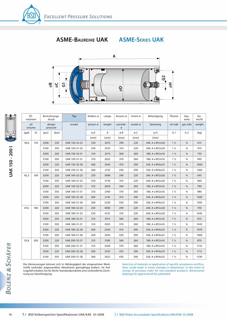
39,6 150 3200 220 UAK 150-32-25 250 3475 290 220 240, 4 x M12x20 1 ½ ¾ 615
5100 350 UAK 150-51-25 250 3525 310 220 240, 4 x M12x20 1 ½ ¾ 915
3200 220 UAK 150-32-31 310 2515 360 260 180, 4 x M12x16 1 ½ ¾ 735
5100 350 UAK 150-51-31 310 2625 370 260 180, 4 x M12x16 1 ½ ¾ 945
3200 220 UAK 150-32-36 360 2045 410 290 330, 4 x M16x25 1 ½ ¾ 1000
5100 350 UAK 150-51-36 360 2135 430 290 330, 4 x M16x25 1 ½ ¾ 1360
42,3 160 3200 220 UAK 160-32-25 250 3680 290 220 240, 4 x M12x20 1 ½ ¾ 645
5100 350 UAK 160-51-25 250 3730 310 220 240, 4 x M12x20 1 ½ ¾ 960
3200 220 UAK 160-32-31 310 2650 360 260 180, 4 x M12x16 1 ½ ¾ 760
5100 350 UAK 160-51-31 310 2760 370 260 180, 4 x M12x16 1 ½ ¾ 980
3200 220 UAK 160-32-36 360 2145 410 290 330, 4 x M16x25 1 ½ ¾ 1020
5100 350 UAK 160-51-36 360 2230 430 290 330, 4 x M16x25 1 ½ ¾ 1395
47,6 180 3200 220 UAK 180-32-25 250 4085 290 220 240, 4 x M12x20 1 ½ ¾ 700
5100 350 UAK 180-51-25 250 4135 310 220 240, 4 x M12x20 1 ½ ¾ 1045
3200 220 UAK 180-32-31 310 2915 360 260 180, 4 x M12x16 1 ½ ¾ 815
5100 350 UAK 180-51-31 310 3025 370 260 180, 4 x M12x16 1 ½ ¾ 1045
3200 220 UAK 180-32-36 360 2340 410 290 330, 4 x M16x25 1 ½ ¾ 1070
5100 350 UAK 180-51-36 360 2430 430 290 330, 4 x M16x25 1 ½ ¾ 1460
52,8 200 3200 220 UAK 200-32-31 310 3180 360 260 180, 4 x M12x16 1 ½ ¾ 870
5100 350 UAK 200-51-31 310 3290 370 260 180, 4 x M12x16 1 ½ ¾ 1110
3200 220 UAK 200-32-36 360 2535 410 290 330, 4 x M16x25 1 ½ ¾ 1115
5100 350 UAK 200-51-36 360 2625 430 290 330, 4 x M16x25 1 ½ ¾ 1530
Die Abmessungen können sich in Abhängigkeit der eingesetzten Werk-stoffe und/oder angewandten Abnahmen geringfügig ändern. Im Auf-tragsfall erhalten Sie für Nicht-Standardprodukte eine verbindliche Zeich-nung zur Genehmigung.
Selection of materials or application of specific acceptance certifica-tions could result in minor changes in dimensions. In the event of receipt of purchase order for non-standard products, dimensional drawings for approval will be submitted.

1.1 BSD Kolbenspeicher-Spezifikationen UAK/KAK 01-2008 1.1 BSD Piston Accumulator Specifications UAK/KAK 01-2008 17
BOLE
NZ
& SC
HÄ
FER
aSme-SerieS UaKaSme-BaUreihe UaK
UA
K 22
5 - 3
25 l
AøB G
1
G2
øH
øD
øC
Öl- volumen
Berechnungs-druck
Typ Kolben-ø Länge Aussen-ø Innen-ø Befestigung Ölseite Gas-seite
Ge-wicht
oil volume
design pressure
model piston-ø length outside-ø
inside-ø fastening oil side gas side weight
[gal] [l] [psi] [bar] ø D A ø B ø C ø H G 1 G 2 [kg]
[mm] [mm] [mm] [mm] [mm]
59,4 225 3200 220 UAK 225-32-31 310 3510 360 260 180, 4 x M12x16 1 ½ ¾ 940
5100 350 UAK 225-51-31 310 3620 370 260 180, 4 x M12x16 1 ½ ¾ 1195
3200 220 UAK 225-32-36 360 2780 410 290 330, 4 x M16x25 1 ½ ¾ 1175
5100 350 UAK 225-51-36 360 2870 430 290 330, 4 x M16x25 1 ½ ¾ 1610
66 250 3200 220 UAK 250-32-31 310 3840 360 260 180, 4 x M12x16 1 ½ ¾ 1005
5100 350 UAK 250-51-31 310 3950 370 260 180, 4 x M12x16 1 ½ ¾ 1280
3200 220 UAK 250-32-36 360 3030 410 290 330, 4 x M16x25 1 ½ ¾ 1235
5100 350 UAK 250-51-36 360 3115 430 290 330, 4 x M16x25 1 ½ ¾ 1695
72,7 275 3200 220 UAK 275-32-31 310 4175 360 260 180, 4 x M12x16 1 ½ ¾ 1075
5100 350 UAK 275-51-31 310 4285 370 260 180, 4 x M12x16 1 ½ ¾ 1360
3200 220 UAK 275-32-36 360 3275 410 290 330, 4 x M16x25 1 ½ ¾ 1290
5100 350 UAK 275-51-36 360 3360 430 290 330, 4 x M16x25 1 ½ ¾ 1780
79,2 300 3200 220 UAK 300-32-31 310 4505 360 260 180, 4 x M12x16 1 ½ ¾ 1145
5100 350 UAK 300-51-31 310 4615 370 260 180, 4 x M12x16 1 ½ ¾ 1445
3200 220 UAK 300-32-36 360 3520 410 290 330, 4 x M16x25 1 ½ ¾ 1350
5100 350 UAK 300-51-36 360 3605 430 290 330, 4 x M16x25 1 ½ ¾ 1865
85,9 325 3200 220 UAK 325-32-31 310 4835 360 260 180, 4 x M12x16 1 ½ ¾ 1215
5100 350 UAK 325-51-31 310 4945 370 260 180, 4 x M12x16 1 ½ ¾ 1530
3200 220 UAK 325-32-36 360 3765 410 290 330, 4 x M16x25 1 ½ ¾ 1410
5100 350 UAK 325-51-36 360 3855 430 290 330, 4 x M16x25 1 ½ ¾ 1950
Die Abmessungen können sich in Abhängigkeit der eingesetzten Werk-stoffe und/oder angewandten Abnahmen geringfügig ändern. Im Auf-tragsfall erhalten Sie für Nicht-Standardprodukte eine verbindliche Zeich-nung zur Genehmigung.
Selection of materials or application of specific acceptance certifica-tions could result in minor changes in dimensions. In the event of receipt of purchase order for non-standard products, dimensional drawings for approval will be submitted.
18 1.1 BSD Kolbenspeicher-Spezifikationen UAK/KAK 01-2008 1.1 BSD Piston Accumulator Specifications UAK/KAK 01-2008
BOLE
NZ
& SC
HÄ
FER
aSme-SerieS UaKaSme-BaUreihe UaK
UA
K 35
0 - 4
50 l
AøB G
1
G2
øH
øD
øC
Öl- volumen
Berechnungs-druck
Typ Kolben-ø Länge Aussen-ø Innen-ø Befestigung Ölseite Gas-seite
Ge-wicht
oil volume
design pressure
model piston-ø length outside-ø
inside-ø fastening oil side gas side weight
[gal] [l] [psi] [bar] ø D A ø B ø C ø H G 1 G 2 [kg]
[mm] [mm] [mm] [mm] [mm]
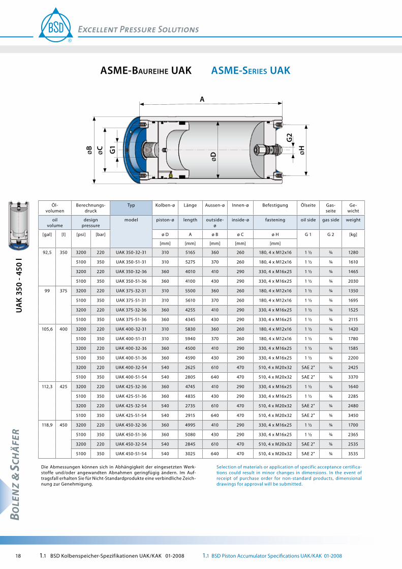
92,5 350 3200 220 UAK 350-32-31 310 5165 360 260 180, 4 x M12x16 1 ½ ¾ 1280
5100 350 UAK 350-51-31 310 5275 370 260 180, 4 x M12x16 1 ½ ¾ 1610
3200 220 UAK 350-32-36 360 4010 410 290 330, 4 x M16x25 1 ½ ¾ 1465
5100 350 UAK 350-51-36 360 4100 430 290 330, 4 x M16x25 1 ½ ¾ 2030
99 375 3200 220 UAK 375-32-31 310 5500 360 260 180, 4 x M12x16 1 ½ ¾ 1350
5100 350 UAK 375-51-31 310 5610 370 260 180, 4 x M12x16 1 ½ ¾ 1695
3200 220 UAK 375-32-36 360 4255 410 290 330, 4 x M16x25 1 ½ ¾ 1525
5100 350 UAK 375-51-36 360 4345 430 290 330, 4 x M16x25 1 ½ ¾ 2115
105,6 400 3200 220 UAK 400-32-31 310 5830 360 260 180, 4 x M12x16 1 ½ ¾ 1420
5100 350 UAK 400-51-31 310 5940 370 260 180, 4 x M12x16 1 ½ ¾ 1780
3200 220 UAK 400-32-36 360 4500 410 290 330, 4 x M16x25 1 ½ ¾ 1585
5100 350 UAK 400-51-36 360 4590 430 290 330, 4 x M16x25 1 ½ ¾ 2200
3200 220 UAK 400-32-54 540 2625 610 470 510, 4 x M20x32 SAE 2" ¾ 2425
5100 350 UAK 400-51-54 540 2805 640 470 510, 4 x M20x32 SAE 2" ¾ 3370
112,3 425 3200 220 UAK 425-32-36 360 4745 410 290 330, 4 x M16x25 1 ½ ¾ 1640
5100 350 UAK 425-51-36 360 4835 430 290 330, 4 x M16x25 1 ½ ¾ 2285
3200 220 UAK 425-32-54 540 2735 610 470 510, 4 x M20x32 SAE 2" ¾ 2480
5100 350 UAK 425-51-54 540 2915 640 470 510, 4 x M20x32 SAE 2" ¾ 3450
118,9 450 3200 220 UAK 450-32-36 360 4995 410 290 330, 4 x M16x25 1 ½ ¾ 1700
5100 350 UAK 450-51-36 360 5080 430 290 330, 4 x M16x25 1 ½ ¾ 2365
3200 220 UAK 450-32-54 540 2845 610 470 510, 4 x M20x32 SAE 2" ¾ 2535
5100 350 UAK 450-51-54 540 3025 640 470 510, 4 x M20x32 SAE 2" ¾ 3535
Die Abmessungen können sich in Abhängigkeit der eingesetzten Werk-stoffe und/oder angewandten Abnahmen geringfügig ändern. Im Auf-tragsfall erhalten Sie für Nicht-Standardprodukte eine verbindliche Zeich-nung zur Genehmigung.
Selection of materials or application of specific acceptance certifica-tions could result in minor changes in dimensions. In the event of receipt of purchase order for non-standard products, dimensional drawings for approval will be submitted.
1.1 BSD Kolbenspeicher-Spezifikationen UAK/KAK 01-2008 1.1 BSD Piston Accumulator Specifications UAK/KAK 01-2008 19
BOLE
NZ
& SC
HÄ
FER
aSme-SerieS UaKaSme-BaUreihe UaK
UA
K 47
5 - 6
50 l
AøB G
1
G2
øH
øD
øC
Öl- volumen
Berechnungs-druck
Typ Kolben-ø Länge Aussen-ø Innen-ø Befestigung Ölseite Gas-seite
Ge-wicht
oil volume
design pressure
model piston-ø length outside-ø
inside-ø fastening oil side gas side weight
[gal] [l] [psi] [bar] ø D A ø B ø C ø H G 1 G 2 [kg]
[mm] [mm] [mm] [mm] [mm]
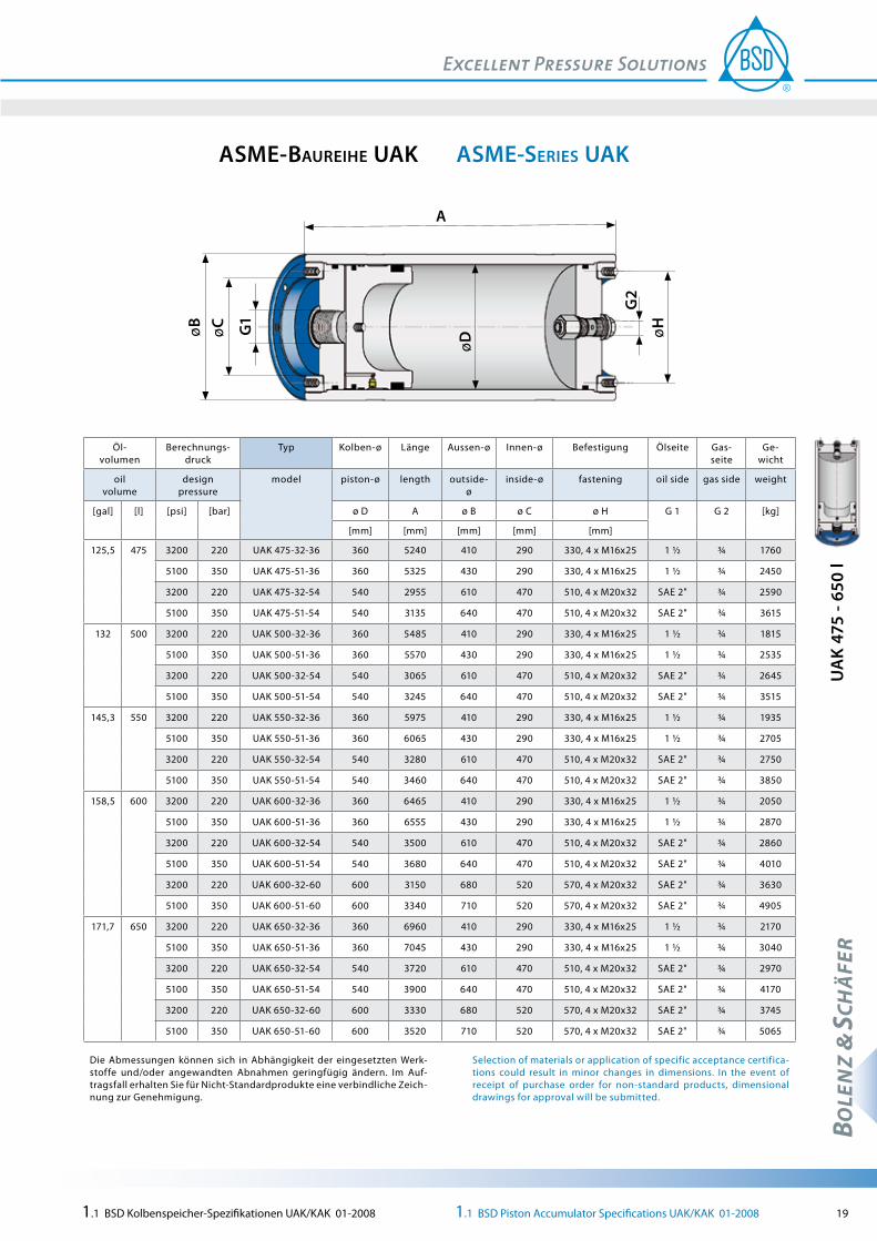
125,5 475 3200 220 UAK 475-32-36 360 5240 410 290 330, 4 x M16x25 1 ½ ¾ 1760
5100 350 UAK 475-51-36 360 5325 430 290 330, 4 x M16x25 1 ½ ¾ 2450
3200 220 UAK 475-32-54 540 2955 610 470 510, 4 x M20x32 SAE 2" ¾ 2590
5100 350 UAK 475-51-54 540 3135 640 470 510, 4 x M20x32 SAE 2" ¾ 3615
132 500 3200 220 UAK 500-32-36 360 5485 410 290 330, 4 x M16x25 1 ½ ¾ 1815
5100 350 UAK 500-51-36 360 5570 430 290 330, 4 x M16x25 1 ½ ¾ 2535
3200 220 UAK 500-32-54 540 3065 610 470 510, 4 x M20x32 SAE 2" ¾ 2645
5100 350 UAK 500-51-54 540 3245 640 470 510, 4 x M20x32 SAE 2" ¾ 3515
145,3 550 3200 220 UAK 550-32-36 360 5975 410 290 330, 4 x M16x25 1 ½ ¾ 1935
5100 350 UAK 550-51-36 360 6065 430 290 330, 4 x M16x25 1 ½ ¾ 2705
3200 220 UAK 550-32-54 540 3280 610 470 510, 4 x M20x32 SAE 2" ¾ 2750
5100 350 UAK 550-51-54 540 3460 640 470 510, 4 x M20x32 SAE 2" ¾ 3850
158,5 600 3200 220 UAK 600-32-36 360 6465 410 290 330, 4 x M16x25 1 ½ ¾ 2050
5100 350 UAK 600-51-36 360 6555 430 290 330, 4 x M16x25 1 ½ ¾ 2870
3200 220 UAK 600-32-54 540 3500 610 470 510, 4 x M20x32 SAE 2" ¾ 2860
5100 350 UAK 600-51-54 540 3680 640 470 510, 4 x M20x32 SAE 2" ¾ 4010
3200 220 UAK 600-32-60 600 3150 680 520 570, 4 x M20x32 SAE 2" ¾ 3630
5100 350 UAK 600-51-60 600 3340 710 520 570, 4 x M20x32 SAE 2" ¾ 4905
171,7 650 3200 220 UAK 650-32-36 360 6960 410 290 330, 4 x M16x25 1 ½ ¾ 2170
5100 350 UAK 650-51-36 360 7045 430 290 330, 4 x M16x25 1 ½ ¾ 3040
3200 220 UAK 650-32-54 540 3720 610 470 510, 4 x M20x32 SAE 2" ¾ 2970
5100 350 UAK 650-51-54 540 3900 640 470 510, 4 x M20x32 SAE 2" ¾ 4170
3200 220 UAK 650-32-60 600 3330 680 520 570, 4 x M20x32 SAE 2" ¾ 3745
5100 350 UAK 650-51-60 600 3520 710 520 570, 4 x M20x32 SAE 2" ¾ 5065
Die Abmessungen können sich in Abhängigkeit der eingesetzten Werk-stoffe und/oder angewandten Abnahmen geringfügig ändern. Im Auf-tragsfall erhalten Sie für Nicht-Standardprodukte eine verbindliche Zeich-nung zur Genehmigung.
Selection of materials or application of specific acceptance certifica-tions could result in minor changes in dimensions. In the event of receipt of purchase order for non-standard products, dimensional drawings for approval will be submitted.
20 1.1 BSD Kolbenspeicher-Spezifikationen UAK/KAK 01-2008 1.1 BSD Piston Accumulator Specifications UAK/KAK 01-2008
BOLE
NZ
& SC
HÄ
FER
aSme-SerieS UaKaSme-BaUreihe UaK
UA
K 70
0 - 8
00 l
AøB G
1
G2
øH
øD
øC
Öl- volumen
Berechnungs-druck
Typ Kolben-ø Länge Aussen-ø Innen-ø Befestigung Ölseite Gas-seite
Ge-wicht
oil volume
design pressure
model piston-ø length outside-ø
inside-ø fastening oil side gas side weight
[gal] [l] [psi] [bar] ø D A ø B ø C ø H G 1 G 2 [kg]
[mm] [mm] [mm] [mm] [mm]
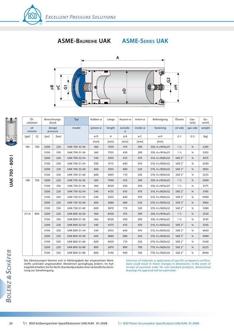
185 700 3200 220 UAK 700-32-36 360 7450 410 290 330, 4 x M16x25 1 ½ ¾ 2285
5100 350 UAK 700-51-36 360 7535 430 290 330, 4 x M16x25 1 ½ ¾ 3205
3200 220 UAK 700-32-54 540 3935 610 470 510, 4 x M20x32 SAE 2" ¾ 3075
5100 350 UAK 700-51-54 540 4115 640 470 510, 4 x M20x32 SAE 2" ¾ 4330
3200 220 UAK 700-32-60 600 3505 680 520 570, 4 x M20x32 SAE 2" ¾ 3855
5100 350 UAK 700-51-60 600 3695 710 520 570, 4 x M20x32 SAE 2" ¾ 5225
198 750 3200 220 UAK 750-32-36 360 7940 410 290 330, 4 x M16x25 1 ½ ¾ 2400
5100 350 UAK 750-51-36 360 8030 430 290 330, 4 x M16x25 1 ½ ¾ 3375
3200 220 UAK 750-32-54 540 4155 610 470 510, 4 x M20x32 SAE 2" ¾ 3185
5100 350 UAK 750-51-54 540 4335 640 470 510, 4 x M20x32 SAE 2" ¾ 4490
3200 220 UAK 750-32-60 600 3680 680 520 570, 4 x M20x32 SAE 2" ¾ 3965
5100 350 UAK 750-51-60 600 3870 710 520 570, 4 x M20x32 SAE 2" ¾ 5380
211,4 800 3200 220 UAK 800-32-36 360 8430 410 290 330, 4 x M16x25 1 ½ ¾ 2520
5100 350 UAK 800-51-36 360 8520 430 290 330, 4 x M16x25 1 ½ ¾ 3545
3200 220 UAK 800-32-54 540 4375 610 470 510, 4 x M20x32 SAE 2" ¾ 3295
5100 350 UAK 800-51-54 540 4555 640 470 510, 4 x M20x32 SAE 2" ¾ 4650
3200 220 UAK 800-32-60 600 3860 680 520 570, 4 x M20x32 SAE 2" ¾ 4080
5100 350 UAK 800-51-60 600 4050 710 520 570, 4 x M20x32 SAE 2" ¾ 5540
3200 220 UAK 800-32-80 800 2870 890 700 770, 4 x M20x32 SAE 2" ¾ 6225
5100 350 UAK 800-51-80 800 3140 940 700 770, 4 x M20x32 SAE 2" ¾ 8940
Die Abmessungen können sich in Abhängigkeit der eingesetzten Werk-stoffe und/oder angewandten Abnahmen geringfügig ändern. Im Auf-tragsfall erhalten Sie für Nicht-Standardprodukte eine verbindliche Zeich-nung zur Genehmigung.
Selection of materials or application of specific acceptance certifica-tions could result in minor changes in dimensions. In the event of receipt of purchase order for non-standard products, dimensional drawings for approval will be submitted.

1.1 BSD Kolbenspeicher-Spezifikationen UAK/KAK 01-2008 1.1 BSD Piston Accumulator Specifications UAK/KAK 01-2008 21
BOLE
NZ
& SC
HÄ
FER
Special connectionS UaKSonDeranSchlüSSe UaK
alternative filling valveS UaKalternative füllventile UaK
Beispiel 1:axialer
Flanschanschluss
example 1:axial flange connection
Beispiel 1: Füllventil für
Membranspeicher M 28 x 1,5
example 1: filling valve for dia-phragm accumulater M 28 x 1,5
Beispiel 2:radialer
Flanschanschluss
example 2:radial flange connection
Beispiel 2: Füllventil mit
Anschluss 7/8" 14 UNF 1A
example 2: Filling valve with connection 7/8" 14 UNF 1A
Beispiel 3:axialer
Flanschanschluss
example 3:axial flange connection
Beispiel 3: Minimess-Füllventil
M16 x 1,5
example 3: Minimess filling valve M 16 x 1,5
Vorstehende Beispiele von Sonderanschlüssen und Gasfüllventilen stellen lediglich eine Auswahl möglicher Varianten dar. Weitere Ausführungen bieten wir auf Anfrage gerne an.
Only a possible selection of special connec-tions and gas filling valves is shown above. We offer further Types on request gladly.
22 1.1 BSD Kolbenspeicher-Spezifikationen UAK/KAK 01-2008 1.1 BSD Piston Accumulator Specifications UAK/KAK 01-2008
BOLE
NZ
& SC
HÄ
FER
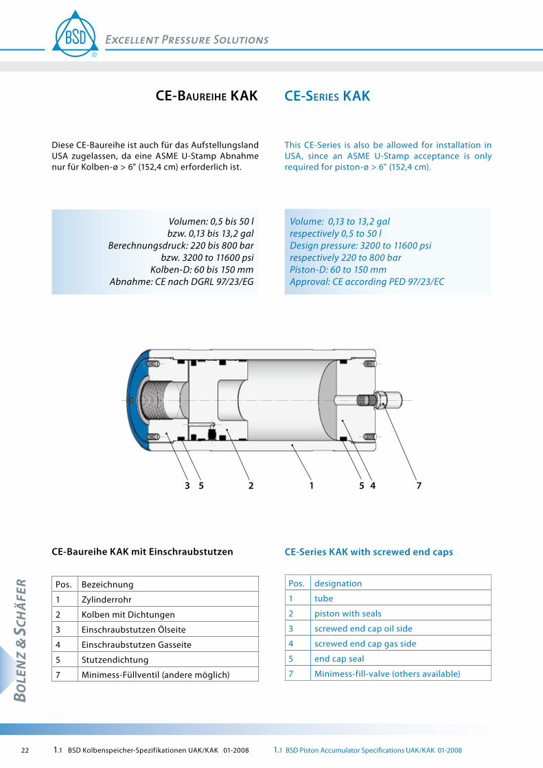
This CE-Series is also be allowed for installation in USA, since an ASME U-Stamp acceptance is only required for piston-ø > 6" (152,4 cm).
Volume: 0,13 to 13,2 gal respectively 0,5 to 50 lDesign pressure: 3200 to 11600 psi respectively 220 to 800 barPiston-D: 60 to 150 mmApproval: CE according PED 97/23/EC
CE-Series KAK with screwed end caps
Pos. designation
1 tube
2 piston with seals
3 screwed end cap oil side
4 screwed end cap gas side
5 end cap seal
7 Minimess-fill-valve (others available)
Diese CE-Baureihe ist auch für das Aufstellungsland USA zugelassen, da eine ASME U-Stamp Abnahme nur für Kolben-ø > 6" (152,4 cm) erforderlich ist.
Volumen: 0,5 bis 50 l bzw. 0,13 bis 13,2 gal
Berechnungsdruck: 220 bis 800 bar bzw. 3200 to 11600 psi
Kolben-D: 60 bis 150 mmAbnahme: CE nach DGRL 97/23/EG
741253 5
CE-Baureihe KAK mit Einschraubstutzen
Pos. Bezeichnung
1 Zylinderrohr
2 Kolben mit Dichtungen
3 Einschraubstutzen Ölseite
4 Einschraubstutzen Gasseite
5 Stutzendichtung
7 Minimess-Füllventil (andere möglich)
ce-SerieS KaKce-BaUreihe KaK

1.1 BSD Kolbenspeicher-Spezifikationen UAK/KAK 01-2008 1.1 BSD Piston Accumulator Specifications UAK/KAK 01-2008 23
BOLE
NZ
& SC
HÄ
FER
A
øB G1
G2
øH
øDÖlvolu-
menBerechnungsdruck Typ Kolben-ø Länge Aussen-ø Befestigung Ölseite Gasseite Gewicht
oil volume design pressure model piston-ø length outside-ø fastening oil side gas side weight
[l] [gal] [bar] [psi] ø D A ø B ø H G 1 G 2 [kg]
[mm] [mm] [mm] [mm]
0,5 0,13 220 3200 KAK 0,5-220-06 60 300 70 55, 2 x M6x10 ½ ¼ 5
375 5400 KAK 0,5-375-06 60 330 80 55, 2 x M6x10 ½ ¼ 8
220 3200 KAK 0,5-220-08 80 230 100 70, 4 x M8x13 ½ ¼ 8
375 5400 KAK 0,5-375-08 80 250 100 70, 4 x M8x13 ½ ¼ 10
220 3200 KAK 0,5-220-10 100 230 125 90, 4 x M8x12 ¾ ¼ 12
375 5400 KAK 0,5-375-10 100 250 125 90, 4 x M8x12 ¾ ¼ 16
800 11600 KAK 0,5-800-10 100 305 170 90, 4 x M8x12 ¼ ¼ 49
1 0,26 220 3200 KAK 01-220-06 60 475 70 55, 2 x M6x10 ½ ¼ 6
375 5400 KAK 01-375-06 60 505 80 55, 2 x M6x10 ½ ¼ 11
220 3200 KAK 01-220-08 80 330 100 70, 4 x M8x13 ½ ¼ 10
375 5400 KAK 01-375-08 80 350 100 70, 4 x M8x13 ½ ¼ 13
220 3200 KAK 01-220-10 100 295 125 90, 4 x M8x12 ¾ ¼ 14
375 5400 KAK 01-375-10 100 315 125 90, 4 x M8x12 ¾ ¼ 18
800 11600 KAK 01-800-10 100 370 170 90, 4 x M8x12 ¼ ¼ 57
1,5 0,4 220 3200 KAK 1,5-220-06 60 655 70 55, 2 x M6x10 ½ ¼ 8
375 5400 KAK 1,5-375-06 60 685 80 55, 2 x M6x10 ½ ¼ 14
220 3200 KAK 1,5-220-08 80 430 100 70, 4 x M8x13 ½ ¼ 12
375 5400 KAK 1,5-375-08 80 450 100 70, 4 x M8x13 ½ ¼ 15
220 3200 KAK 1,5-220-10 100 355 125 90, 4 x M8x12 ¾ ¼ 16
375 5400 KAK 1,5-375-10 100 375 125 90, 4 x M8x12 ¾ ¼ 20
800 11600 KAK 1,5-800-10 100 430 170 90, 4 x M8x12 ¼ ¼ 64
2 0,53 220 3200 KAK 02-220-06 60 830 70 55, 2 x M6x10 ½ ¼ 9
375 5400 KAK 02-375-06 60 860 80 55, 2 x M6x10 ½ ¼ 17
220 3200 KAK 02-220-08 80 530 100 70, 4 x M8x13 ½ ¼ 14
375 5400 KAK 02-375-08 80 550 100 70, 4 x M8x13 ½ ¼ 17
220 3200 KAK 02-220-10 100 420 125 90, 4 x M8x12 ¾ ¼ 17
375 5400 KAK 02-375-10 100 440 125 90, 4 x M8x12 ¾ ¼ 22
800 11600 KAK 02-800-10 100 495 170 90, 4 x M8x12 ¼ ¼ 71
Die Abmessungen können sich in Abhängigkeit der eingesetzten Werkstoffe und/oder angewandten Abnahmen geringfügig ändern. Im Auftragsfall erhalten Sie für Nicht-Standardprodukte eine verbind-liche Zeichnung zur Genehmigung.
Selection of materials or application of specific acceptance certifica-tions could result in minor changes in dimensions. In the event of re-ceipt of purchase order for non-standard products, dimensional draw-ings for approval will be submitted.
ce-SerieS KaKce-BaUreihe KaK
KA
K 0,
5 - 2
l

24 1.1 BSD Kolbenspeicher-Spezifikationen UAK/KAK 01-2008 1.1 BSD Piston Accumulator Specifications UAK/KAK 01-2008
BOLE
NZ
& SC
HÄ
FER
KA
K 2,
5 - 4
l
A
øB G1
G2
øH
øDÖlvolu-
menBerechnungsdruck Typ Kolben-ø Länge Aussen-ø Befestigung Ölseite Gasseite Gewicht
oil volume design pressure model piston-ø length outside-ø fastening oil side gas side weight
[l] [gal] [bar] [psi] ø D A ø B ø H G 1 G 2 [kg]
[mm] [mm] [mm] [mm]
2,5 0,7 220 3200 KAK 2,5-220-06 60 1005 70 55, 2 x M6x10 ½ ¼ 10
375 5400 KAK 2,5-375-06 60 1035 80 55, 2 x M6x10 ½ ¼ 21
220 3200 KAK 2,5-220-08 80 630 100 70, 4 x M8x13 ½ ¼ 17
375 5400 KAK 2,5-375-08 80 650 100 70, 4 x M8x13 ½ ¼ 19
220 3200 KAK 2,5-220-10 100 485 125 90, 4 x M8x12 ¾ ¼ 19
375 5400 KAK 2,5-375-10 100 505 125 90, 4 x M8x12 ¾ ¼ 24
800 11600 KAK 2,5-800-10 100 560 170 90, 4 x M8x12 ¼ ¼ 79
3 0,8 220 3200 KAK 03-220-06 60 1185 70 55, 2 x M6x10 ½ ¼ 12
375 5400 KAK 03-375-06 60 1215 80 55, 2 x M6x10 ½ ¼ 24
220 3200 KAK 03-220-08 80 730 100 70, 4 x M8x13 ½ ¼ 19
375 5400 KAK 03-375-08 80 750 100 70, 4 x M8x13 ½ ¼ 21
220 3200 KAK 03-220-10 100 550 125 90, 4 x M8x12 ¾ ¼ 21
375 5400 KAK 03-375-10 100 570 125 90, 4 x M8x12 ¾ ¼ 27
800 11600 KAK 03-800-10 100 620 170 90, 4 x M8x12 ¼ ¼ 86
220 3200 KAK 03-220-15 150 360 170 125, 4 x M12x20 1 ¼ 31
350 5100 KAK 03-400-15 150 405 180 125, 4 x M12x20 1 ¼ 48
4 1,1 220 3200 KAK 04-220-06 60 1535 70 55, 2 x M6x10 ½ ¼ 15
375 5400 KAK 04-375-06 60 1565 80 55, 2 x M6x10 ½ ¼ 30
220 3200 KAK 04-220-08 80 930 100 70, 4 x M8x13 ½ ¼ 23
375 5400 KAK 04-375-08 80 950 100 70, 4 x M8x13 ½ ¼ 26
220 3200 KAK 04-220-10 100 675 125 90, 4 x M8x12 ¾ ¼ 24
375 5400 KAK 04-375-10 100 695 125 90, 4 x M8x12 ¾ ¼ 31
800 11600 KAK 04-800-10 100 750 170 90, 4 x M8x12 ¼ ¼ 101
220 3200 KAK 04-220-15 150 420 170 125, 4 x M12x20 1 ¼ 34
350 5100 KAK 04-400-15 150 460 180 125, 4 x M12x20 1 ¼ 52
Die Abmessungen können sich in Abhängigkeit der eingesetzten Werkstoffe und/oder angewandten Abnahmen geringfügig ändern. Im Auftragsfall erhalten Sie für Nicht-Standardprodukte eine verbind-liche Zeichnung zur Genehmigung.
Selection of materials or application of specific acceptance certifica-tions could result in minor changes in dimensions. In the event of re-ceipt of purchase order for non-standard products, dimensional draw-ings for approval will be submitted.
ce-SerieS KaKce-BaUreihe KaK

1.1 BSD Kolbenspeicher-Spezifikationen UAK/KAK 01-2008 1.1 BSD Piston Accumulator Specifications UAK/KAK 01-2008 25
BOLE
NZ
& SC
HÄ
FER
A
øB G1
G2
øH
øDÖlvolu-
menBerechnungsdruck Typ Kolben-ø Länge Aussen-ø Befestigung Ölseite Gasseite Gewicht
oil volume design pressure model piston-ø length outside-ø fastening oil side gas side weight
[l] [gal] [bar] [psi] ø D A ø B ø H G 1 G 2 [kg]
[mm] [mm] [mm] [mm]
5 1,3 220 3200 KAK 05-220-06 60 1890 70 55, 2 x M6x10 ½ ¼ 18
375 5400 KAK 05-375-06 60 1920 80 55, 2 x M6x10 ½ ¼ 36
220 3200 KAK 05-220-08 80 1125 100 70, 4 x M8x13 ½ ¼ 28
375 5400 KAK 05-375-08 80 1145 100 70, 4 x M8x13 ½ ¼ 30
220 3200 KAK 05-220-10 100 805 125 90, 4 x M8x12 ¾ ¼ 28
375 5400 KAK 05-375-10 100 825 125 90, 4 x M8x12 ¾ ¼ 36
800 11600 KAK 05-800-10 100 875 170 90, 4 x M8x12 ¼ ¼ 116
220 3200 KAK 05-220-15 150 475 170 125, 4 x M12x20 1 ¼ 36
350 5100 KAK 05-400-15 150 515 180 125, 4 x M12x20 1 ¼ 55
6 1,6 220 3200 KAK 06-220-08 80 1325 100 70, 4 x M8x13 ½ ¼ 32
375 5400 KAK 06-375-08 80 1345 100 70, 4 x M8x13 ½ ¼ 35
220 3200 KAK 06-220-10 100 930 125 90, 4 x M8x12 ¾ ¼ 31
375 5400 KAK 06-375-10 100 950 125 90, 4 x M8x12 ¾ ¼ 40
800 11600 KAK 06-800-10 100 1005 170 90, 4 x M8x12 ¼ ¼ 131
220 3200 KAK 06-220-15 150 530 170 125, 4 x M12x20 1 ¼ 38
350 5100 KAK 06-400-15 150 575 180 125, 4 x M12x20 1 ¼ 59
8 2,1 220 3200 KAK 08-220-08 80 1725 100 70, 4 x M8x13 ½ ¼ 41
375 5400 KAK 08-375-08 80 1745 100 70, 4 x M8x13 ½ ¼ 44
220 3200 KAK 08-220-10 100 1185 125 90, 4 x M8x12 ¾ ¼ 38
375 5400 KAK 08-375-10 100 1205 125 90, 4 x M8x12 ¾ ¼ 49
800 11600 KAK 08-800-10 100 1260 170 90, 4 x M8x12 ¼ ¼ 161
220 3200 KAK 08-220-15 150 645 170 125, 4 x M12x20 1 ¼ 43
350 5100 KAK 08-400-15 150 685 180 125, 4 x M12x20 1 ¼ 65
10 2,6 220 3200 KAK 10-220-10 100 1440 125 90, 4 x M8x12 ¾ ¼ 45
375 5400 KAK 10-375-10 100 1460 125 90, 4 x M8x12 ¾ ¼ 58
800 11600 KAK 10-800-10 100 1515 170 90, 4 x M8x12 ¼ ¼ 191
220 3200 KAK 10-220-15 150 760 170 125, 4 x M12x20 1 ¼ 47
350 5100 KAK 10-400-15 150 800 180 125, 4 x M12x20 1 ¼ 72
Die Abmessungen können sich in Abhängigkeit der eingesetzten Werkstoffe und/oder angewandten Abnahmen geringfügig ändern. Im Auftragsfall erhalten Sie für Nicht-Standardprodukte eine verbind-liche Zeichnung zur Genehmigung.
Selection of materials or application of specific acceptance certifica-tions could result in minor changes in dimensions. In the event of re-ceipt of purchase order for non-standard products, dimensional draw-ings for approval will be submitted.
ce-SerieS KaKce-BaUreihe KaK
KA
K 5
- 10
l

26 1.1 BSD Kolbenspeicher-Spezifikationen UAK/KAK 01-2008 1.1 BSD Piston Accumulator Specifications UAK/KAK 01-2008
BOLE
NZ
& SC
HÄ
FER
A
øB G1
G2
øH
øDÖlvolu-
menBerechnungsdruck Typ Kolben-ø Länge Aussen-ø Befestigung Ölseite Gasseite Gewicht
oil volume design pressure model piston-ø length outside-ø fastening oil side gas side weight
[l] [gal] [bar] [psi] ø D A ø B ø H G 1 G 2 [kg]
[mm] [mm] [mm] [mm]
12 3,2 220 3200 KAK 12-220-10 100 1695 125 90, 4 x M8x12 ¾ ¼ 52
375 5400 KAK 12-375-10 100 1715 125 90, 4 x M8x12 ¾ ¼ 66
800 11600 KAK 12-800-10 100 1770 170 90, 4 x M8x12 ¼ ¼ 220
220 3200 KAK 12-220-15 150 870 170 125, 4 x M12x20 1 ¼ 52
350 5100 KAK 12-400-15 150 915 180 125, 4 x M12x20 1 ¼ 79
15 4 220 3200 KAK 15-220-10 100 2075 125 90, 4 x M8x12 ¾ ¼ 62
375 5400 KAK 15-375-10 100 2095 125 90, 4 x M8x12 ¾ ¼ 80
220 3200 KAK 15-220-15 150 1040 170 125, 4 x M12x20 1 ¼ 58
350 5100 KAK 15-400-15 150 1085 180 125, 4 x M12x20 1 ¼ 90
20 5,3 220 3200 KAK 20-220-15 150 1325 170 125, 4 x M12x20 1 ¼ 69
350 5100 KAK 20-400-15 150 1365 180 125, 4 x M12x20 1 ¼ 107
25 6,6 220 3200 KAK 25-220-15 150 1605 170 125, 4 x M12x20 1 ¼ 81
350 5100 KAK 25-400-15 150 1650 180 125, 4 x M12x20 1 ¼ 142
30 7,9 220 3200 KAK 30-220-15 150 1890 170 125, 4 x M12x20 1 ¼ 92
350 5100 KAK 30-400-15 150 1930 180 125, 4 x M12x20 1 ¼ 141
35 9,2 220 3200 KAK 35-220-15 150 2175 170 125, 4 x M12x20 1 ¼ 103
350 5100 KAK 35-400-15 150 2215 180 125, 4 x M12x20 1 ¼ 159
40 10,6 220 3200 KAK 40-220-15 150 2455 170 125, 4 x M12x20 1 ¼ 114
350 5100 KAK 40-400-15 150 2500 180 125, 4 x M12x20 1 ¼ 176
45 11,9 220 3200 KAK 45-220-15 150 2740 170 125, 4 x M12x20 1 ¼ 125
350 5100 KAK 45-400-15 150 2780 180 125, 4 x M12x20 1 ¼ 194
50 13,2 220 3200 KAK 50-220-15 150 3020 170 125, 4 x M12x20 1 ¼ 136
350 5100 KAK 50-400-15 150 3065 180 125, 4 x M12x20 1 ¼ 211
Die Abmessungen können sich in Abhängigkeit der eingesetzten Werkstoffe und/oder angewandten Abnahmen geringfügig ändern. Im Auftragsfall erhalten Sie für Nicht-Standardprodukte eine verbind-liche Zeichnung zur Genehmigung.
Selection of materials or application of specific acceptance certifica-tions could result in minor changes in dimensions. In the event of re-ceipt of purchase order for non-standard products, dimensional draw-ings for approval will be submitted.
ce-SerieS KaKce-BaUreihe KaK
KA
K 12
- 50
l

1.1 BSD Kolbenspeicher-Spezifikationen UAK/KAK 01-2008 1.1 BSD Piston Accumulator Specifications UAK/KAK 01-2008 27
BOLE
NZ
& SC
HÄ
FER
Special connectionS KaKSonDeranSchlüSSe KaK
alternative filling valveS KaKalternative füllventile KaK
Beispiel 1:axialer
Flanschanschluss
example 1:axial flange connection
Beispiel 1: Füllventil für
Membranspeicher M 28 x 1,5
example 1: filling valve for dia-phragm accumulater M 28 x 1,5
Beispiel 2:radialer
Flanschanschluss
example 2:radial flange connection
Beispiel 2: Füllventil mit
Anschluss 7/8" 14 UNF 1A
example 2: Filling valve with connection 7/8" 14 UNF 1A
Beispiel 3:axialer
Flanschanschluss
example 3:axial flange connection
Beispiel 3: BSD Gas-Füllventil mit Anschluss 3/4"
example 3: BSD Gas fill valve with connection 3/4"
Vorstehende Beispiele von Sonderanschlüssen und Gasfüllventilen stellen lediglich eine Auswahl möglicher Varianten dar. Weitere Ausführungen bieten wir auf Anfrage gerne an.
Only a possible selection of special connec-tions and gas filling valves is shown above. We offer further types on request gladly.
28 1.1 BSD Kolbenspeicher-Spezifikationen UAK/KAK 01-2008 1.1 BSD Piston Accumulator Specifications UAK/KAK 01-2008
BOLE
NZ
& SC
HÄ
FER
BOLENZ & SCHÄFER GmbH
Lahnstraße 34 D - 35216 Biedenkopf-Eckelshausen
Telefon: + 49 64 61 933 - 0 Fax: + 49 64 61 933 - 161 E-Mail: [email protected] Internet www.bolenz-schaefer.de
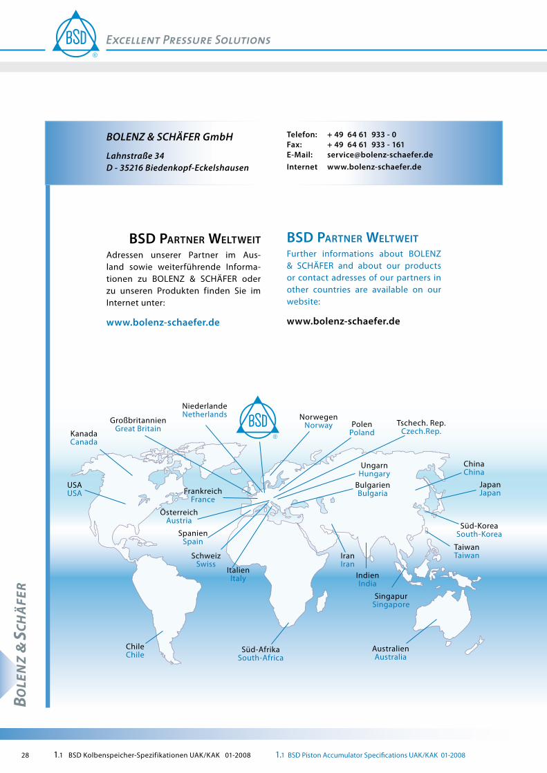
BSD partner WeltWeitAdressen unserer Partner im Aus-land sowie weiterführende Informa-tionen zu BOLENZ & SCHÄFER oder zu unseren Produkten finden Sie im Internet unter:
www.bolenz-schaefer.de
BSD partner WeltWeitFurther informations about BOLENZ & SCHÄFER and about our products or contact adresses of our partners in other countries are available on our website:
www.bolenz-schaefer.de
NiederlandeNetherlands Norwegen
NorwayGroßbritannienGreat Britain
KanadaCanada
PolenPoland
FrankreichFrance
ÖsterreichAustria
SpanienSpain
SchweizSwiss
USAUSA
Tschech. Rep.Czech.Rep.
ChinaChina
JapanJapan
Süd-KoreaSouth-Korea
ItalienItaly
IranIran
UngarnHungary
ChileChile
IndienIndia
BulgarienBulgaria
Süd-AfrikaSouth-Africa
SingapurSingapore
TaiwanTaiwan
AustralienAustralia