b/s/h/ error codes and service programmes ph -...
TRANSCRIPT
B/S/H/ Error codes and service programmes PH
BSH BOSCH UND SIEMENS HAUSGERAETE GMBH Document-No.: 56500000097059_ARA_EN.doc Sheet-No.
P200_IC5_E3_MCT_G_SE Material-No.: 9000459454 Revision B
1 of 31 The reproduction, transmission or use of this document or its contests is not permitted without express written authority. Offenders will be liable for damages. All rights including rights created by patent grant or registration of a utility model or design are reserved. Copyright reserved
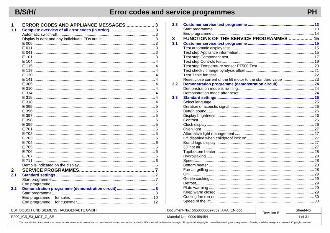
1 ERROR CODES AND APPLIANCE MESSAGES...................... 3 1.1 Complete overview of all error codes (in order).......................................... 3
Automatic switch-off.......................................................................................... 3 Display is dark and any individual LEDs are lit................................................. 3 E 005................................................................................................................. 3 E 011................................................................................................................. 3 E 041................................................................................................................. 3 E 101................................................................................................................. 3 E 104................................................................................................................. 4 E 115................................................................................................................. 4 E 119................................................................................................................. 4 E 120................................................................................................................. 4 E 141................................................................................................................. 4 E 305................................................................................................................. 4 E 310................................................................................................................. 4 E 314................................................................................................................. 4 E 315................................................................................................................. 4 E 318................................................................................................................. 4 E 395................................................................................................................. 5 E 396................................................................................................................. 5 E 397................................................................................................................. 5 E 398................................................................................................................. 5 E 399................................................................................................................. 5 E 701................................................................................................................. 5 E 702................................................................................................................. 5 E 703................................................................................................................. 5 E 704................................................................................................................. 6 E 705................................................................................................................. 6 E 706................................................................................................................. 6 E 707................................................................................................................. 6 E 711................................................................................................................. 6 Demo is indicated on the display...................................................................... 6
2 SERVICE PROGRAMMES......................................................... 7 2.1 Standard settings ........................................................................................... 7
Start programme............................................................................................... 7 End programme ................................................................................................ 7
2.2 Demonstration programme (demonstration circuit) ................................... 8 Start programme............................................................................................... 8 End programme for sales ............................................................................ 10 End programme for customer...................................................................... 12
2.3 Customer service test programme ............................................................. 13 Start programme .............................................................................................13 End programme ..............................................................................................14
3 FUNCTIONS OF THE SERVICE PROGRAMMES .................. 15 3.1 Customer service test programme ............................................................. 15
Test automatic display test .............................................................................15 Test step Appliance information ..................................................................... 15 Test step Component test............................................................................... 17 Test step Controls test .................................................................................... 19 Test step Temperature sensor PT500 Test .................................................... 20 Test check / change pyrolysis offset...............................................................21 Test Table fan test ..........................................................................................22 Reset close current of the lift motor to the standard value ............................. 23
3.2 Demonstration programme (demonstration circuit) .................................24 Demonstration mode is running......................................................................24 Demonstration mode after reset ..................................................................... 24
3.3 Standard settings..........................................................................................25 Select language ..............................................................................................25 Duration of acoustic signal..............................................................................26 Button sound...................................................................................................26 Display brightness...........................................................................................26 Contrast...........................................................................................................26 Clock display...................................................................................................26 Oven light ........................................................................................................27 Alternative light management .........................................................................27 Lift disabled when childproof lock on ..............................................................27 Brand logo display .......................................................................................... 27 3D hot air.........................................................................................................27 Top/bottom heater...........................................................................................28 HydroBaking ...................................................................................................28 Speed..............................................................................................................28 Bottom heater .................................................................................................28 Fan-air grilling .................................................................................................28 Grill..................................................................................................................29 Gentle cooking ................................................................................................29 Defrost.............................................................................................................29 Plate warming .................................................................................................29 Keep warm closed ..........................................................................................29 Cooling fan run-on ..........................................................................................30 Speed of the lift ...............................................................................................30
B/S/H/ Error codes and service programmes PH
BSH BOSCH UND SIEMENS HAUSGERAETE GMBH Document-No.: 56500000097059_ARA_EN.doc Sheet-No.
P200_IC5_E3_MCT_G_SE Material-No.: 9000459454 Revision B
2 of 31 The reproduction, transmission or use of this document or its contests is not permitted without express written authority. Offenders will be liable for damages. All rights including rights created by patent grant or registration of a utility model or design are reserved. Copyright reserved
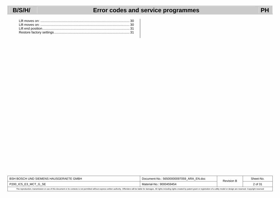
Lift moves on: ................................................................................................. 30 Lift moves on: ................................................................................................. 30 Lift end position............................................................................................... 31 Restore factory settings .................................................................................. 31
B/S/H/ Error codes and service programmes PH
BSH BOSCH UND SIEMENS HAUSGERAETE GMBH Document-No.: 56500000097059_ARA_EN.doc Sheet-No.
P200_IC5_E3_MCT_G_SE Material-No.: 9000459454 Revision B
3 of 31 The reproduction, transmission or use of this document or its contests is not permitted without express written authority. Offenders will be liable for damages. All rights including rights created by patent grant or registration of a utility model or design are reserved. Copyright reserved
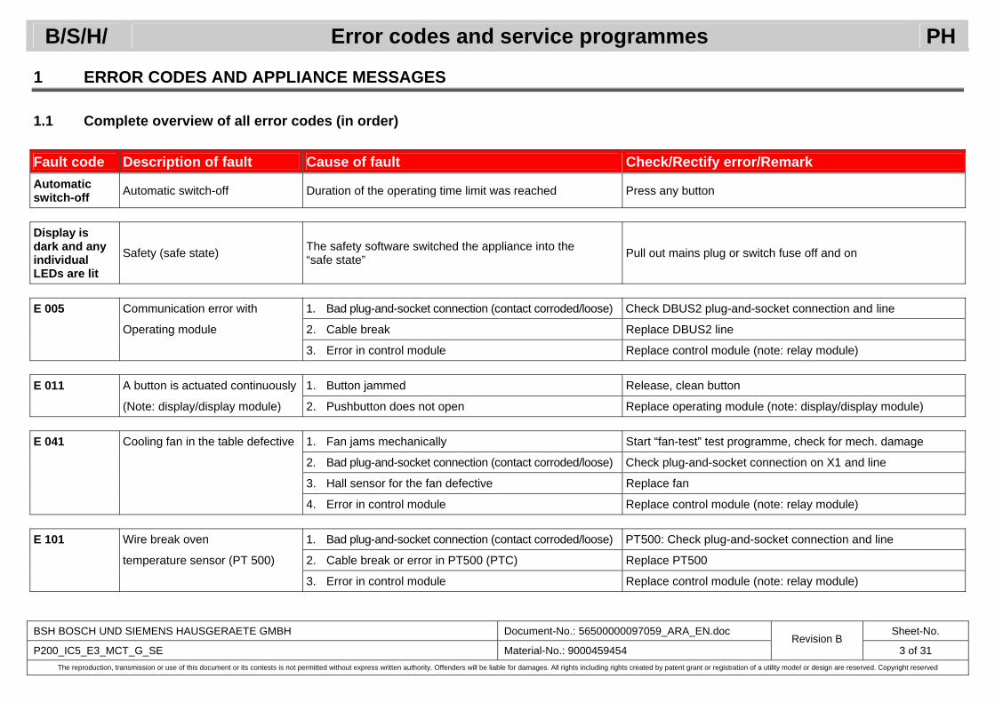
1 ERROR CODES AND APPLIANCE MESSAGES
1.1 Complete overview of all error codes (in order)
Fault code Description of fault Cause of fault Check/Rectify error/Remark Automatic switch-off Automatic switch-off Duration of the operating time limit was reached Press any button
Display is dark and any individual LEDs are lit
Safety (safe state) The safety software switched the appliance into the “safe state” Pull out mains plug or switch fuse off and on
E 005 Communication error with 1. Bad plug-and-socket connection (contact corroded/loose) Check DBUS2 plug-and-socket connection and line
Operating module 2. Cable break Replace DBUS2 line
3. Error in control module Replace control module (note: relay module) E 011 A button is actuated continuously 1. Button jammed Release, clean button
(Note: display/display module) 2. Pushbutton does not open Replace operating module (note: display/display module) E 041 Cooling fan in the table defective 1. Fan jams mechanically Start “fan-test” test programme, check for mech. damage
2. Bad plug-and-socket connection (contact corroded/loose) Check plug-and-socket connection on X1 and line
3. Hall sensor for the fan defective Replace fan
4. Error in control module Replace control module (note: relay module) E 101 Wire break oven 1. Bad plug-and-socket connection (contact corroded/loose) PT500: Check plug-and-socket connection and line
temperature sensor (PT 500) 2. Cable break or error in PT500 (PTC) Replace PT500
3. Error in control module Replace control module (note: relay module)
B/S/H/ Error codes and service programmes PH
BSH BOSCH UND SIEMENS HAUSGERAETE GMBH Document-No.: 56500000097059_ARA_EN.doc Sheet-No.
P200_IC5_E3_MCT_G_SE Material-No.: 9000459454 Revision B
4 of 31 The reproduction, transmission or use of this document or its contests is not permitted without express written authority. Offenders will be liable for damages. All rights including rights created by patent grant or registration of a utility model or design are reserved. Copyright reserved
Fault code Description of fault Cause of fault Check/Rectify error/Remark E 104 Short-circuit oven 1. Bad plug-and-socket connection (contact corroded/loose) PT500: Check plug-and-socket connection and line
temperature sensor (PT 500) 2. Cable break or PT500 (PTC) is defective Replace PT500
3. Error in control module Replace control module (note: relay module) E 115 Temperature too high Temperature in the cooking compartment is too high Leave oven to cool down and preselect higher temperature E 119 PT500 reference Internal error in control module Replace control module (note: relay module) E 120 PT500 configuration Internal error in control module Replace control module (note: relay module)
E 141 DBUS – 2 1. Brief fault in DBUS2 communication due to an EMC fault Press clock button
(Note: relay module) 2. Bad plug-and-socket connection (contact corroded/loose) Check DBUS – 2 plug-and-socket connection
3. DBUS – 2 telegram repetitions Replace control module (note: relay module) E 305 Communication error with 1. Bad plug-and-socket connection (contact corroded/loose) Check DBUS – 2 plug-and-socket connection
Control module 2. Cable break Check DBUS – 2 line
3. Error in the operating module Replace operating module (note: display/display module) E 310 Error in data memory Internal error in control module Replace control module (note: relay module) E 314 EEPROM parameter error Internal error in control module Replace control module (note: relay module)
E 315 Temperature on the PT500 too high TPt > 425 °C if no pyrolysis Replace control module
or Leave appliance to cool down TPt > 535 °C (always error) Start temperature sensor PT500 test E 318 Wrong control module USA control module installed Replace control module (note: relay module)
B/S/H/ Error codes and service programmes PH
BSH BOSCH UND SIEMENS HAUSGERAETE GMBH Document-No.: 56500000097059_ARA_EN.doc Sheet-No.
P200_IC5_E3_MCT_G_SE Material-No.: 9000459454 Revision B
5 of 31 The reproduction, transmission or use of this document or its contests is not permitted without express written authority. Offenders will be liable for damages. All rights including rights created by patent grant or registration of a utility model or design are reserved. Copyright reserved
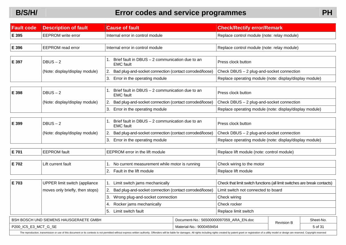
Fault code Description of fault Cause of fault Check/Rectify error/Remark E 395 EEPROM write error Internal error in control module Replace control module (note: relay module) E 396 EEPROM read error Internal error in control module Replace control module (note: relay module)
E 397 DBUS – 2 1. Brief fault in DBUS – 2 communication due to an EMC fault Press clock button
(Note: display/display module) 2. Bad plug-and-socket connection (contact corroded/loose) Check DBUS – 2 plug-and-socket connection
3. Error in the operating module Replace operating module (note: display/display module)
E 398 DBUS – 2 1. Brief fault in DBUS – 2 communication due to an EMC fault Press clock button
(Note: display/display module) 2. Bad plug-and-socket connection (contact corroded/loose) Check DBUS – 2 plug-and-socket connection
3. Error in the operating module Replace operating module (note: display/display module)
E 399 DBUS – 2 1. Brief fault in DBUS – 2 communication due to an EMC fault Press clock button
(Note: display/display module) 2. Bad plug-and-socket connection (contact corroded/loose) Check DBUS – 2 plug-and-socket connection
3. Error in the operating module Replace operating module (note: display/display module) E 701 EEPROM fault EEPROM error in the lift module Replace lift module (note: control module) E 702 Lift current fault 1. No current measurement while motor is running Check wiring to the motor
2. Fault in the lift module Replace lift module E 703 UPPER limit switch (appliance 1. Limit switch jams mechanically Check that limit switch functions (all limit switches are break contacts)
moves only briefly, then stops) 2. Bad plug-and-socket connection (contact corroded/loose) Limit switch not connected to board
3. Wrong plug-and-socket connection Check wiring
4. Rocker jams mechanically Check rocker
5. Limit switch fault Replace limit switch
B/S/H/ Error codes and service programmes PH
BSH BOSCH UND SIEMENS HAUSGERAETE GMBH Document-No.: 56500000097059_ARA_EN.doc Sheet-No.
P200_IC5_E3_MCT_G_SE Material-No.: 9000459454 Revision B
6 of 31 The reproduction, transmission or use of this document or its contests is not permitted without express written authority. Offenders will be liable for damages. All rights including rights created by patent grant or registration of a utility model or design are reserved. Copyright reserved
Fault code Description of fault Cause of fault Check/Rectify error/Remark
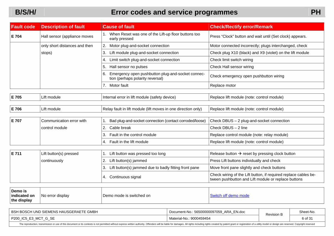
E 704 Hall sensor (appliance moves 1. When Reset was one of the Lift-up floor buttons too early pressed Press “Clock” button and wait until (Set clock) appears.
only short distances and then 2. Motor plug-and-socket connection Motor connected incorrectly; plugs interchanged, check
stops) 3. Lift module plug-and-socket connection Check plug X10 (black) and X9 (violet) on the lift module
4. Limit switch plug-and-socket connection Check limit switch wiring
5. Hall sensor no pulses Check Hall sensor wiring
6. Emergency open pushbutton plug-and-socket connec-tion (perhaps polarity reversal) Check emergency open pushbutton wiring
7. Motor fault Replace motor E 705 Lift module Internal error in lift module (safety device) Replace lift module (note: control module) E 706 Lift module Relay fault in lift module (lift moves in one direction only) Replace lift module (note: control module) E 707 Communication error with 1. Bad plug-and-socket connection (contact corroded/loose) Check DBUS – 2 plug-and-socket connection
control module 2. Cable break Check DBUS – 2 line
3. Fault in the control module Replace control module (note: relay module)
4. Fault in the lift module Replace lift module (note: control module) E 711 Lift button(s) pressed 1. Lift button was pressed too long Release button reset by pressing clock button
continuously 2. Lift button(s) jammed Press Lift buttons individually and check
3. Lift button(s) jammed due to badly fitting front pane Move front pane slightly and check buttons
4. Continuous signal Check wiring of the Lift button, if required replace cables be-tween pushbutton and Lift module or replace buttons
Demo is indicated on the display
No error display Demo mode is switched on Switch off demo mode
B/S/H/ Error codes and service programmes PH
BSH BOSCH UND SIEMENS HAUSGERAETE GMBH Document-No.: 56500000097059_ARA_EN.doc Sheet-No.
P200_IC5_E3_MCT_G_SE Material-No.: 9000459454 Revision B
7 of 31 The reproduction, transmission or use of this document or its contests is not permitted without express written authority. Offenders will be liable for damages. All rights including rights created by patent grant or registration of a utility model or design are reserved. Copyright reserved
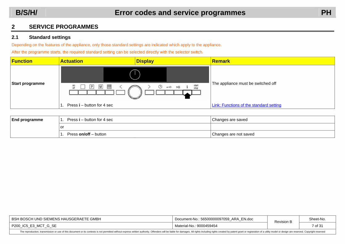
2 SERVICE PROGRAMMES
2.1 Standard settings Depending on the features of the appliance, only those standard settings are indicated which apply to the appliance.
After the programme starts, the required standard setting can be selected directly with the selector switch.
Function Actuation Display Remark
Start programme The appliance must be switched off
1. Press i – button for 4 sec Link: Functions of the standard setting
End programme 1. Press i – button for 4 sec Changes are saved
or
1. Press on/off – button Changes are not saved

B/S/H/ Error codes and service programmes PH
BSH BOSCH UND SIEMENS HAUSGERAETE GMBH Document-No.: 56500000097059_ARA_EN.doc Sheet-No.
P200_IC5_E3_MCT_G_SE Material-No.: 9000459454 Revision B
8 of 31 The reproduction, transmission or use of this document or its contests is not permitted without express written authority. Offenders will be liable for damages. All rights including rights created by patent grant or registration of a utility model or design are reserved. Copyright reserved
2.2 Demonstration programme (demonstration circuit)
Function Actuation Display Remark
Start programme
1. Press on/off – button
2. Press the “Types of heating” – button
3. Turn selector switch to right until top/bottom heating is displayed
4. Press the > – button
B/S/H/ Error codes and service programmes PH
BSH BOSCH UND SIEMENS HAUSGERAETE GMBH Document-No.: 56500000097059_ARA_EN.doc Sheet-No.
P200_IC5_E3_MCT_G_SE Material-No.: 9000459454 Revision B
9 of 31 The reproduction, transmission or use of this document or its contests is not permitted without express written authority. Offenders will be liable for damages. All rights including rights created by patent grant or registration of a utility model or design are reserved. Copyright reserved
Function Actuation Display Remark
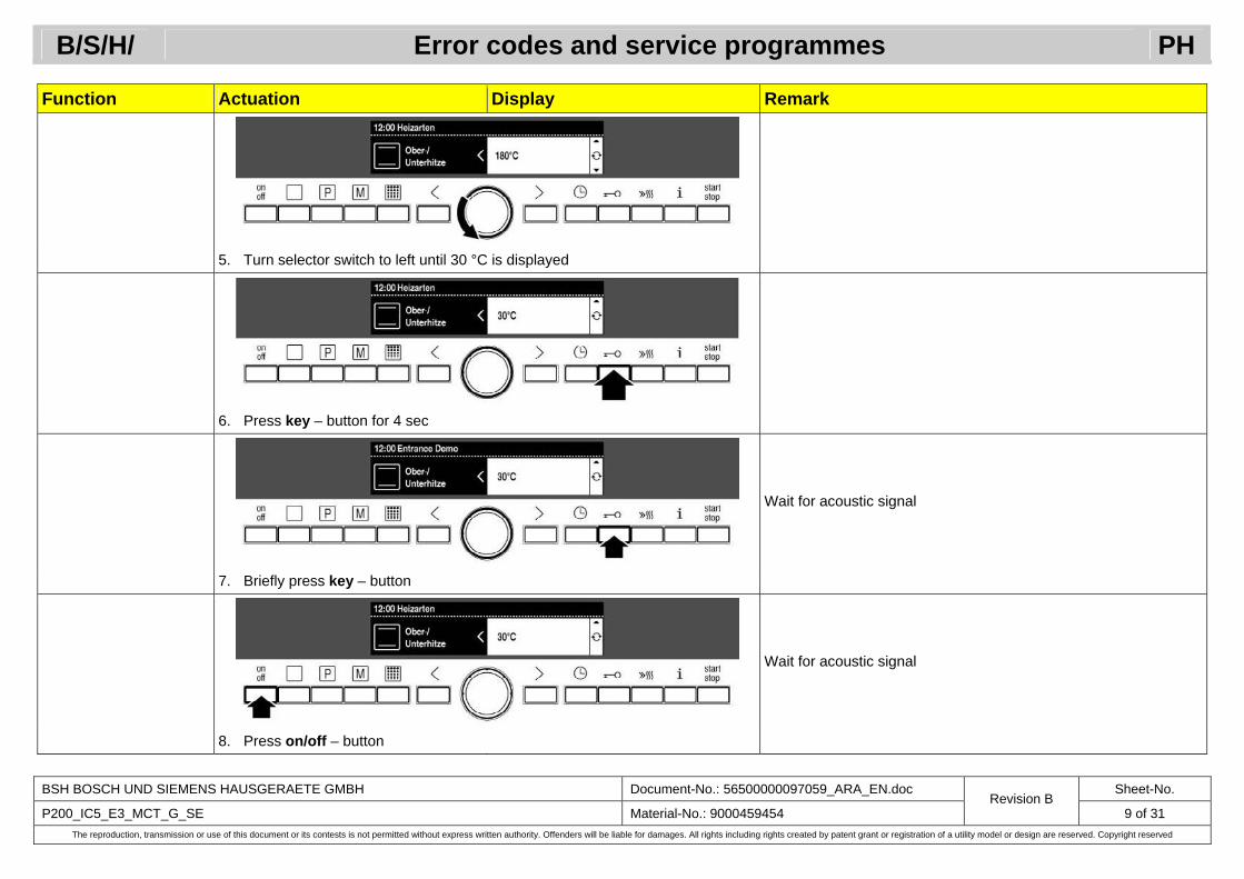
5. Turn selector switch to left until 30 °C is displayed
6. Press key – button for 4 sec
Wait for acoustic signal
7. Briefly press key – button
Wait for acoustic signal
8. Press on/off – button

B/S/H/ Error codes and service programmes PH
BSH BOSCH UND SIEMENS HAUSGERAETE GMBH Document-No.: 56500000097059_ARA_EN.doc Sheet-No.
P200_IC5_E3_MCT_G_SE Material-No.: 9000459454 Revision B
10 of 31 The reproduction, transmission or use of this document or its contests is not permitted without express written authority. Offenders will be liable for damages. All rights including rights created by patent grant or registration of a utility model or design are reserved. Copyright reserved
Function Actuation Display Remark
Demonstration programme is switched on If an operating mode is started, 3 bars of the heating up bar display and demo are always indicated simultaneously Link: Demonstration programme
End programme for sales
1. Press on/off – button
2. Press the “Types of heating” – button
3. Turn selector switch to right until top/bottom heating is displayed
B/S/H/ Error codes and service programmes PH
BSH BOSCH UND SIEMENS HAUSGERAETE GMBH Document-No.: 56500000097059_ARA_EN.doc Sheet-No.
P200_IC5_E3_MCT_G_SE Material-No.: 9000459454 Revision B
11 of 31 The reproduction, transmission or use of this document or its contests is not permitted without express written authority. Offenders will be liable for damages. All rights including rights created by patent grant or registration of a utility model or design are reserved. Copyright reserved
Function Actuation Display Remark
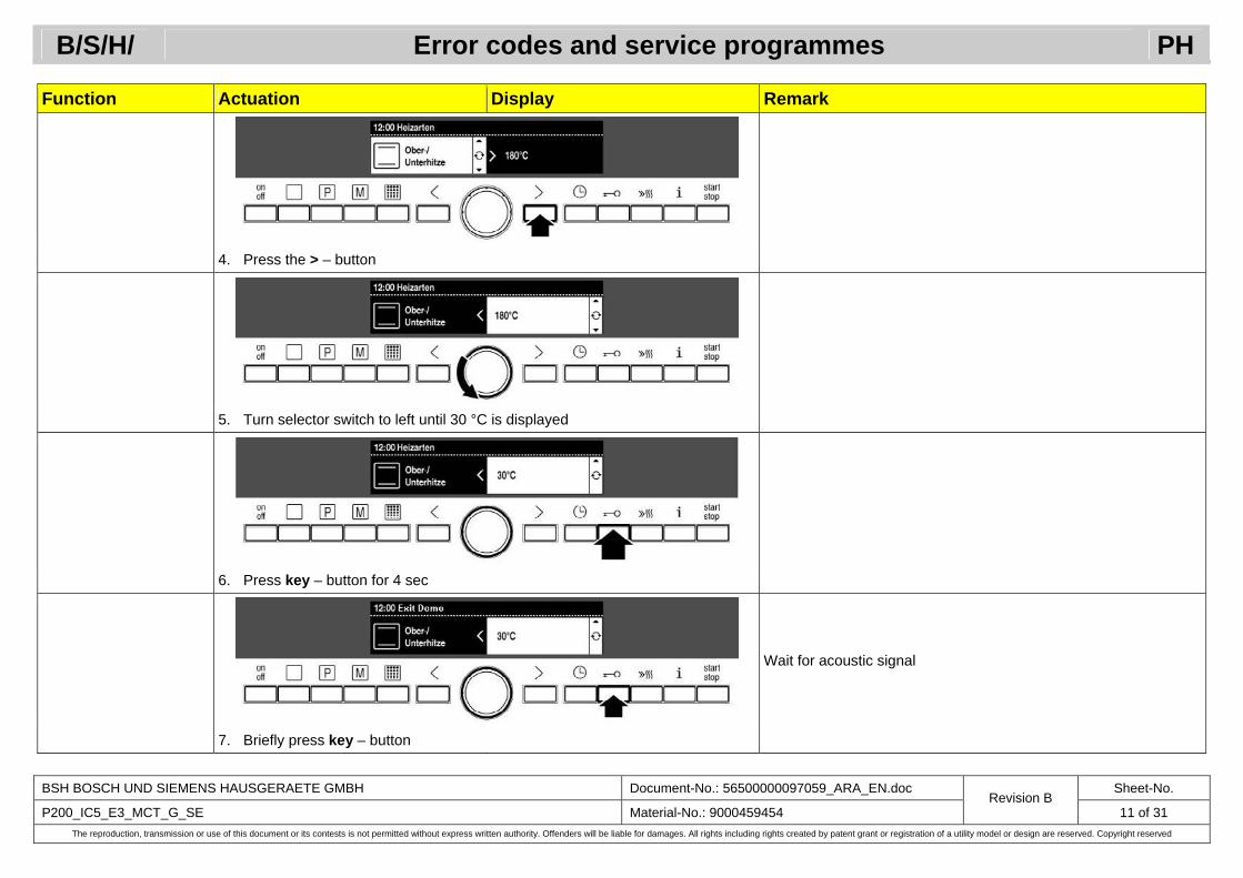
4. Press the > – button
5. Turn selector switch to left until 30 °C is displayed
6. Press key – button for 4 sec
Wait for acoustic signal
7. Briefly press key – button

B/S/H/ Error codes and service programmes PH
BSH BOSCH UND SIEMENS HAUSGERAETE GMBH Document-No.: 56500000097059_ARA_EN.doc Sheet-No.
P200_IC5_E3_MCT_G_SE Material-No.: 9000459454 Revision B
12 of 31 The reproduction, transmission or use of this document or its contests is not permitted without express written authority. Offenders will be liable for damages. All rights including rights created by patent grant or registration of a utility model or design are reserved. Copyright reserved
Function Actuation Display Remark
Wait for acoustic signal
8. Press on/off – button
Demonstration programme is switched off If an operating mode is started, 3 bars of the heating up bar display are not indicated simultaneously and no demo is displayed
1. Connect appliance to power supply Beforehand disconnect appliance from the power supply for at least 20 seconds
End programme for customer
Press the key button within 2 min
2. Press key – button for 4 sec
B/S/H/ Error codes and service programmes PH
BSH BOSCH UND SIEMENS HAUSGERAETE GMBH Document-No.: 56500000097059_ARA_EN.doc Sheet-No.
P200_IC5_E3_MCT_G_SE Material-No.: 9000459454 Revision B
13 of 31 The reproduction, transmission or use of this document or its contests is not permitted without express written authority. Offenders will be liable for damages. All rights including rights created by patent grant or registration of a utility model or design are reserved. Copyright reserved
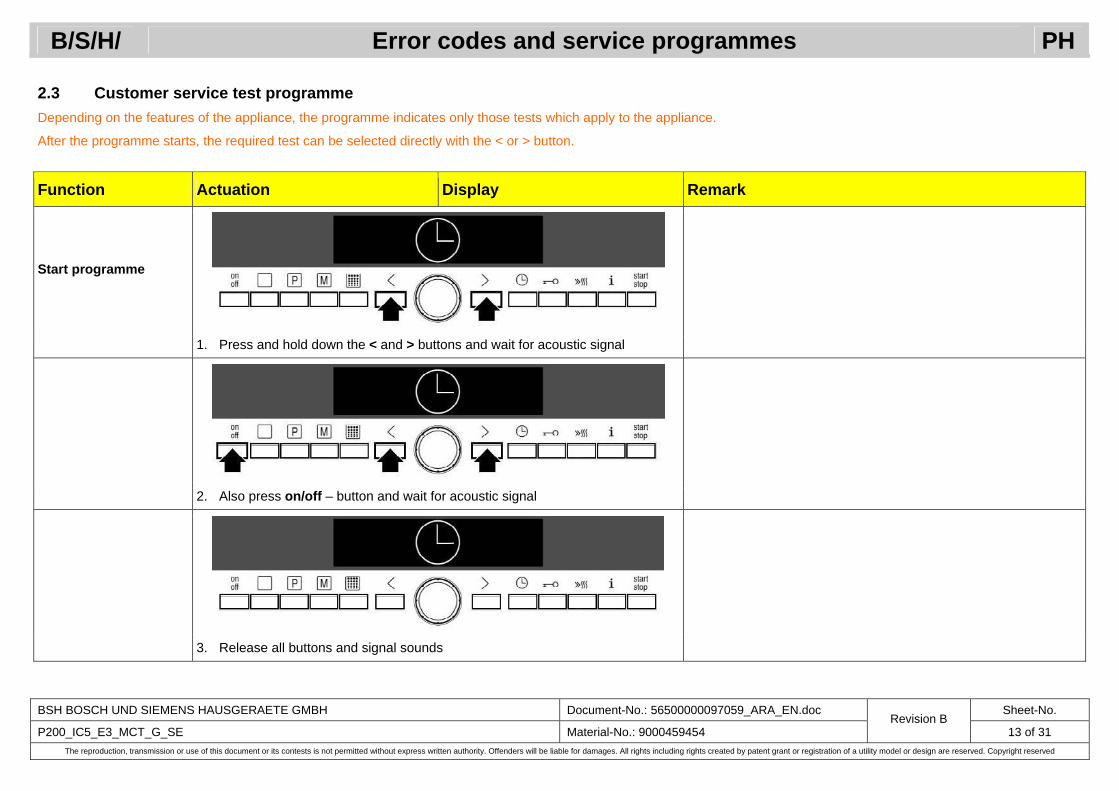
2.3 Customer service test programme Depending on the features of the appliance, the programme indicates only those tests which apply to the appliance.
After the programme starts, the required test can be selected directly with the < or > button.
Function Actuation Display Remark
Start programme
1. Press and hold down the < and > buttons and wait for acoustic signal
2. Also press on/off – button and wait for acoustic signal
3. Release all buttons and signal sounds

B/S/H/ Error codes and service programmes PH
BSH BOSCH UND SIEMENS HAUSGERAETE GMBH Document-No.: 56500000097059_ARA_EN.doc Sheet-No.
P200_IC5_E3_MCT_G_SE Material-No.: 9000459454 Revision B
14 of 31 The reproduction, transmission or use of this document or its contests is not permitted without express written authority. Offenders will be liable for damages. All rights including rights created by patent grant or registration of a utility model or design are reserved. Copyright reserved
Function Actuation Display Remark
All segments of the clear text display are lit Link: Tests in the customer service test programme
Control not actuated After 10 minutes and save the changes
Mains voltage interrupted Immediately End programme
Press on/off button/press stop button for 4 sec After approx. 4 seconds and save the changes

B/S/H/ Error codes and service programmes PH
BSH BOSCH UND SIEMENS HAUSGERAETE GMBH Document-No.: 56500000097059_ARA_EN.doc Sheet-No.
P200_IC5_E3_MCT_G_SE Material-No.: 9000459454 Revision B
15 of 31 The reproduction, transmission or use of this document or its contests is not permitted without express written authority. Offenders will be liable for damages. All rights including rights created by patent grant or registration of a utility model or design are reserved. Copyright reserved
3 FUNCTIONS OF THE SERVICE PROGRAMMES
3.1 Customer service test programme
Function Actuation Display Remark
Test automatic display test
Following successful selection of customer service test pro-gramme, all segments of the clear text are lit.
1. Press > – button 1st test level is activated automatically
Test step Appliance information Module display Hardware version
customer service device info Hardware UI 0815
Software version 2. Turn rotary selector one notch to the right Software UI xx xx xx xx = numbers from 0 to 9
EEPROM version 3. Turn rotary selector one notch to the right EEPROM version UI xx xx
Module control Hardware version 4. Turn rotary selector one notch to the right Hardware CM
xx xx
Software version 5. Turn rotary selector one notch to the right Software CM xx xx
EEPROM version 6. Turn rotary selector one notch to the right EEPROM version CM xx xx
Lift control module Hardware version 7. Turn rotary selector one notch to the right Hardware LM
xx xx
Software version 8. Turn rotary selector one notch to the right Software LM xx xx
EEPROM version 9. Turn rotary selector one notch to the right EEPROM version LM xx xx

B/S/H/ Error codes and service programmes PH
BSH BOSCH UND SIEMENS HAUSGERAETE GMBH Document-No.: 56500000097059_ARA_EN.doc Sheet-No.
P200_IC5_E3_MCT_G_SE Material-No.: 9000459454 Revision B
16 of 31 The reproduction, transmission or use of this document or its contests is not permitted without express written authority. Offenders will be liable for damages. All rights including rights created by patent grant or registration of a utility model or design are reserved. Copyright reserved
Function Actuation Display Remark
End Test 1 10. Press > – button Select Test 2 “component test”
B/S/H/ Error codes and service programmes PH
BSH BOSCH UND SIEMENS HAUSGERAETE GMBH Document-No.: 56500000097059_ARA_EN.doc Sheet-No.
P200_IC5_E3_MCT_G_SE Material-No.: 9000459454 Revision B
17 of 31 The reproduction, transmission or use of this document or its contests is not permitted without express written authority. Offenders will be liable for damages. All rights including rights created by patent grant or registration of a utility model or design are reserved. Copyright reserved
Function Actuation Display Remark
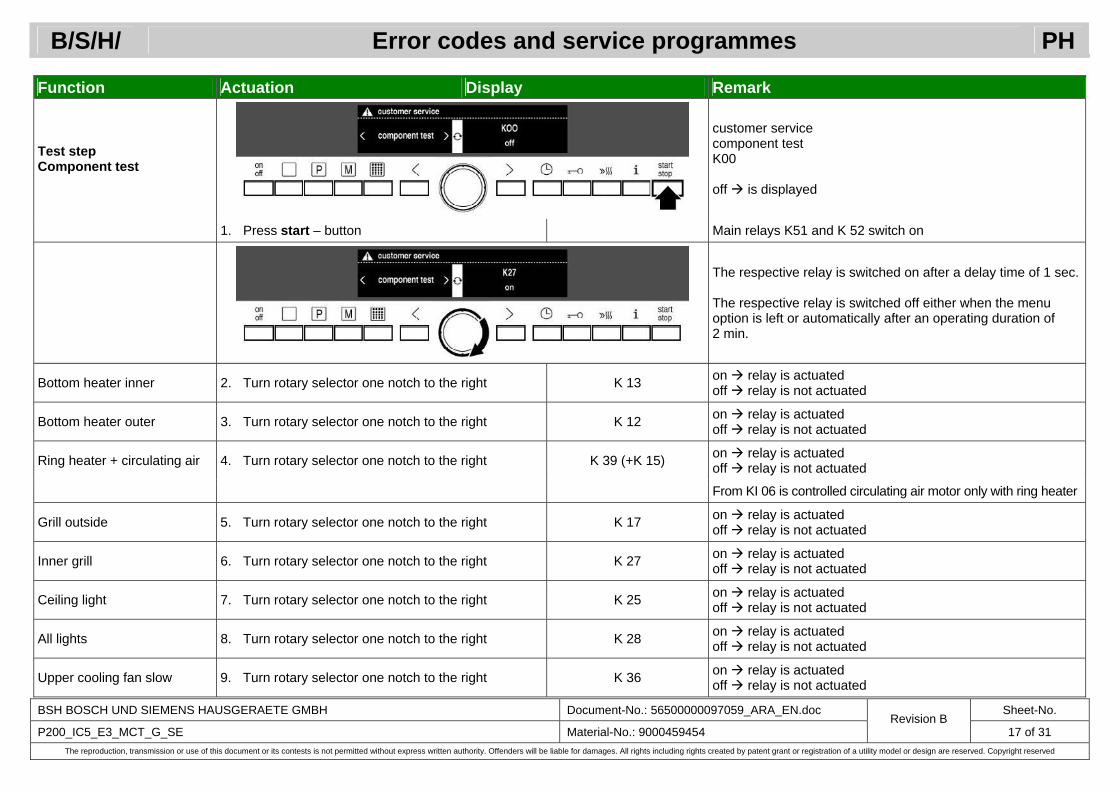
Test step Component test
customer service component test K00 off is displayed
1. Press start – button Main relays K51 and K 52 switch on
The respective relay is switched on after a delay time of 1 sec. The respective relay is switched off either when the menu option is left or automatically after an operating duration of 2 min.
Bottom heater inner 2. Turn rotary selector one notch to the right K 13 on relay is actuated off relay is not actuated
Bottom heater outer 3. Turn rotary selector one notch to the right K 12 on relay is actuated off relay is not actuated
Ring heater + circulating air 4. Turn rotary selector one notch to the right K 39 (+K 15) on relay is actuated off relay is not actuated
From KI 06 is controlled circulating air motor only with ring heater
Grill outside 5. Turn rotary selector one notch to the right K 17 on relay is actuated off relay is not actuated
Inner grill 6. Turn rotary selector one notch to the right K 27 on relay is actuated off relay is not actuated
Ceiling light 7. Turn rotary selector one notch to the right K 25 on relay is actuated off relay is not actuated
All lights 8. Turn rotary selector one notch to the right K 28 on relay is actuated off relay is not actuated
Upper cooling fan slow 9. Turn rotary selector one notch to the right K 36 on relay is actuated off relay is not actuated
B/S/H/ Error codes and service programmes PH
BSH BOSCH UND SIEMENS HAUSGERAETE GMBH Document-No.: 56500000097059_ARA_EN.doc Sheet-No.
P200_IC5_E3_MCT_G_SE Material-No.: 9000459454 Revision B
18 of 31 The reproduction, transmission or use of this document or its contests is not permitted without express written authority. Offenders will be liable for damages. All rights including rights created by patent grant or registration of a utility model or design are reserved. Copyright reserved
Function Actuation Display Remark
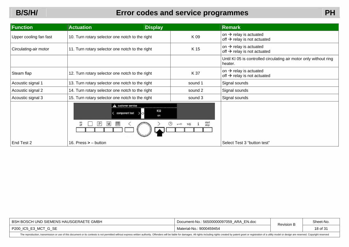
Upper cooling fan fast 10. Turn rotary selector one notch to the right K 09 on relay is actuated off relay is not actuated
Circulating-air motor 11. Turn rotary selector one notch to the right K 15 on relay is actuated off relay is not actuated
Until KI 05 is controlled circulating air motor only without ring heater.
Steam flap 12. Turn rotary selector one notch to the right K 37 on relay is actuated off relay is not actuated
Acoustic signal 1 13. Turn rotary selector one notch to the right sound 1 Signal sounds
Acoustic signal 2 14. Turn rotary selector one notch to the right sound 2 Signal sounds
Acoustic signal 3 15. Turn rotary selector one notch to the right sound 3 Signal sounds
End Test 2 16. Press > – button Select Test 3 “button test”
B/S/H/ Error codes and service programmes PH
BSH BOSCH UND SIEMENS HAUSGERAETE GMBH Document-No.: 56500000097059_ARA_EN.doc Sheet-No.
P200_IC5_E3_MCT_G_SE Material-No.: 9000459454 Revision B
19 of 31 The reproduction, transmission or use of this document or its contests is not permitted without express written authority. Offenders will be liable for damages. All rights including rights created by patent grant or registration of a utility model or design are reserved. Copyright reserved
Function Actuation Display Remark
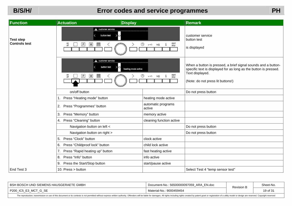
Test step Controls test
customer service button test is displayed
When a button is pressed, a brief signal sounds and a button-specific text is displayed for as long as the button is pressed. Text displayed. (Note: do not press lit buttons!)
on/off button Do not press button
1. Press “Heating mode” button heating mode active
2. Press “Programmes” button automatic programs active
3. Press “Memory” button memory active
4. Press “Cleaning” button cleaning function active
Navigation button on left < Do not press button
Navigation button on right > Do not press button
5. Press “Clock” button clock active
6. Press “Childproof lock” button child lock active
7. Press “Rapid heating up” button fast heating active
8. Press “Info” button info active
9. Press the Start/Stop button start/pause active
End Test 3 10. Press > button Select Test 4 “temp sensor test”

B/S/H/ Error codes and service programmes PH
BSH BOSCH UND SIEMENS HAUSGERAETE GMBH Document-No.: 56500000097059_ARA_EN.doc Sheet-No.
P200_IC5_E3_MCT_G_SE Material-No.: 9000459454 Revision B
20 of 31 The reproduction, transmission or use of this document or its contests is not permitted without express written authority. Offenders will be liable for damages. All rights including rights created by patent grant or registration of a utility model or design are reserved. Copyright reserved
Function Actuation Display Remark
Test step Temperature sensor PT500 Test
customer service PT500 test (current temperature is displayed) The duration of the test automatically starts immediately. However, there is no power to the two grill heating elements (if available with rapid heating up) until the start button is pressed.
1. Press start – button
During the test the current oven temperature (e.g. 0105 = 105 °C) is indicated at the bottom of the display. After 5 min operation the heating phase is automatically ended.
No temperature control Do not run this test more than twice in succession!
End Test 4 2. Press > – button Select Test 6 “pyrolysis offset”

B/S/H/ Error codes and service programmes PH
BSH BOSCH UND SIEMENS HAUSGERAETE GMBH Document-No.: 56500000097059_ARA_EN.doc Sheet-No.
P200_IC5_E3_MCT_G_SE Material-No.: 9000459454 Revision B
21 of 31 The reproduction, transmission or use of this document or its contests is not permitted without express written authority. Offenders will be liable for damages. All rights including rights created by patent grant or registration of a utility model or design are reserved. Copyright reserved
Function Actuation Display Remark
Test check / change pyrolysis offset
customer service pyrolysis offset (current pyrolysis offset is displayed)
1. Select required offset value with To left To right
Set rotary selector –15 °C to –1 °C 1 °C to 15 °C
2. Press on/off – button, or End programme and save the changes
End Test 6 2. Press > – button Select Test 16 “fan test”
B/S/H/ Error codes and service programmes PH
BSH BOSCH UND SIEMENS HAUSGERAETE GMBH Document-No.: 56500000097059_ARA_EN.doc Sheet-No.
P200_IC5_E3_MCT_G_SE Material-No.: 9000459454 Revision B
22 of 31 The reproduction, transmission or use of this document or its contests is not permitted without express written authority. Offenders will be liable for damages. All rights including rights created by patent grant or registration of a utility model or design are reserved. Copyright reserved
Function Actuation Display Remark
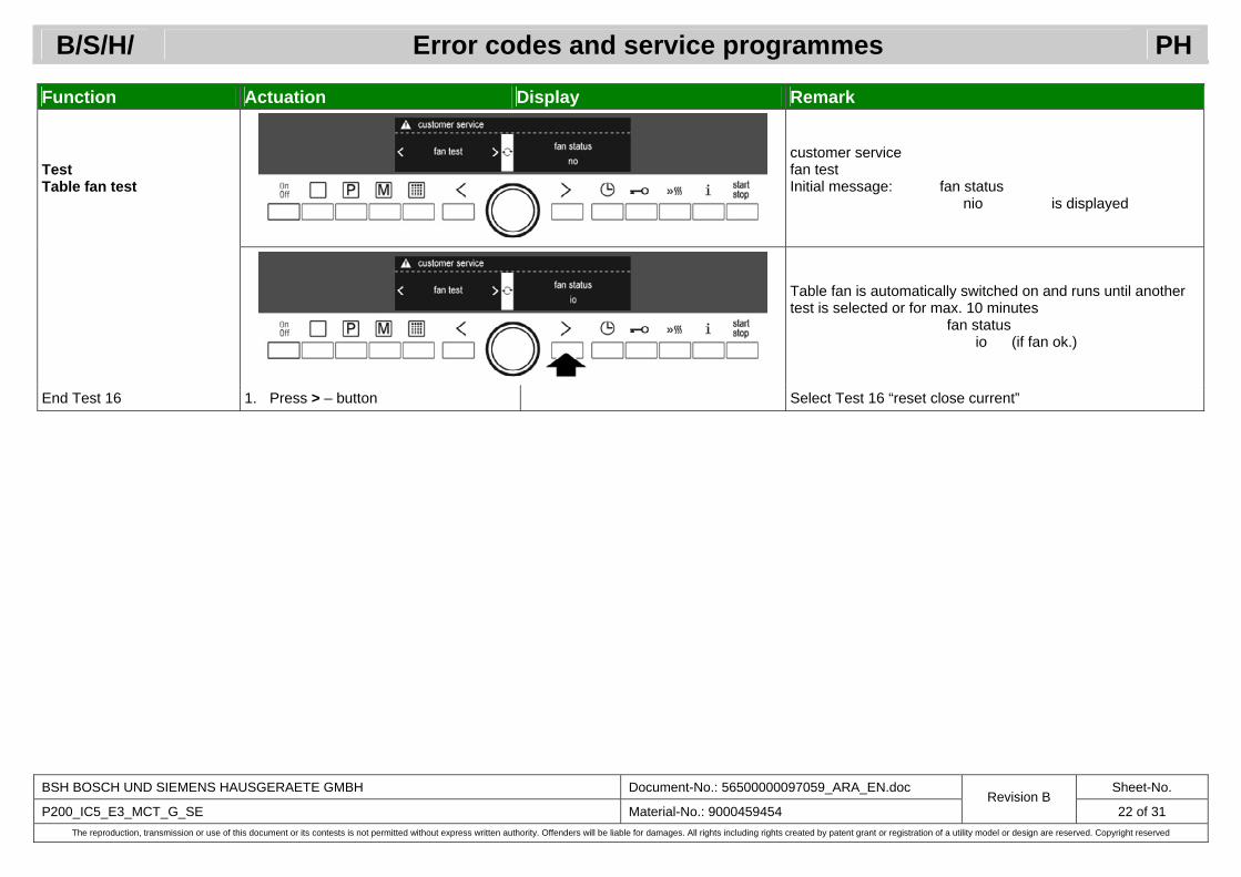
Test Table fan test
customer service fan test Initial message: fan status nio is displayed
Table fan is automatically switched on and runs until another test is selected or for max. 10 minutes fan status io (if fan ok.)
End Test 16 1. Press > – button Select Test 16 “reset close current”

B/S/H/ Error codes and service programmes PH
BSH BOSCH UND SIEMENS HAUSGERAETE GMBH Document-No.: 56500000097059_ARA_EN.doc Sheet-No.
P200_IC5_E3_MCT_G_SE Material-No.: 9000459454 Revision B
23 of 31 The reproduction, transmission or use of this document or its contests is not permitted without express written authority. Offenders will be liable for damages. All rights including rights created by patent grant or registration of a utility model or design are reserved. Copyright reserved
Function Actuation Display Remark
Reset close current of the lift motor to the standard value
customer service reset close current (preselected “no” is displayed)
1. Turn rotary selector
If the appliance closes “badly” or the lift motor or the complete drive was replaced, the close current value must be reset
2. Press M – button yes (note: reset) A signal sounds to acknowledge acceptance
End Test 17 3. Press > – button Select Test 1: “device info”

B/S/H/ Error codes and service programmes PH
BSH BOSCH UND SIEMENS HAUSGERAETE GMBH Document-No.: 56500000097059_ARA_EN.doc Sheet-No.
P200_IC5_E3_MCT_G_SE Material-No.: 9000459454 Revision B
24 of 31 The reproduction, transmission or use of this document or its contests is not permitted without express written authority. Offenders will be liable for damages. All rights including rights created by patent grant or registration of a utility model or design are reserved. Copyright reserved
3.2 Demonstration programme (demonstration circuit)
Function Actuation Display Remark
Demonstration mode is running
The functions of the appliance are simulated without actuation of the heaters and fans. The oven light is lit. If an operating mode is started, 3 bars of the heating up bar display and demo are always indicated simultaneously.
Start heating mode Link: Start demonstration programme
Demonstration mode after reset
The function continues to remain active. After an operating mode starts, demo remains on the display.
B/S/H/ Error codes and service programmes PH
BSH BOSCH UND SIEMENS HAUSGERAETE GMBH Document-No.: 56500000097059_ARA_EN.doc Sheet-No.
P200_IC5_E3_MCT_G_SE Material-No.: 9000459454 Revision B
25 of 31 The reproduction, transmission or use of this document or its contests is not permitted without express written authority. Offenders will be liable for damages. All rights including rights created by patent grant or registration of a utility model or design are reserved. Copyright reserved
3.3 Standard settings
Function Actuation Display Remark
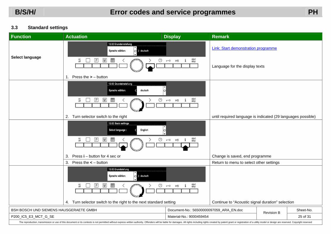
Select language
Link: Start demonstration programme Language for the display texts
1. Press the > – button
2. Turn selector switch to the right until required language is indicated (29 languages possible)
3. Press i – button for 4 sec or Change is saved, end programme 3. Press the < – button Return to menu to select other settings
4. Turn selector switch to the right to the next standard setting Continue to “Acoustic signal duration” selection
B/S/H/ Error codes and service programmes PH
BSH BOSCH UND SIEMENS HAUSGERAETE GMBH Document-No.: 56500000097059_ARA_EN.doc Sheet-No.
P200_IC5_E3_MCT_G_SE Material-No.: 9000459454 Revision B
26 of 31 The reproduction, transmission or use of this document or its contests is not permitted without express written authority. Offenders will be liable for damages. All rights including rights created by patent grant or registration of a utility model or design are reserved. Copyright reserved
Function Actuation Display Remark Duration of acoustic signal 1. Turn selector switch until Duration of acoustic
signal: Setting how long the signal sounds after a duration has
2. Press the > – button Medium elapsed 3. Turn rotary selector Long Until medium (2min) short (10sec) or long (5min) is indicated 4. Press i – button for 4 sec or Change is saved, end programme 4. Press the < button Return to menu to select other settings Button sound 1. Turn selector switch until Button sound: 2. Press the > – button Off Acknowledgement sounds when a button is pressed 3. Turn rotary selector On (on the control panel) 4. Press i – button for 4 sec or Change is saved, end programme 4. Press the < – button Return to menu to select other settings Display brightness 1. Turn selector switch until Luminosity of display: 2. Press the > – button Day Display light 3. Turn rotary selector Night Until middle or night is indicated 4. Press i – button for 4 sec or Change is saved, end programme 4. Press the < – button Return to menu to select other settings Contrast 1. Turn selector switch until Adjust individually: Adjust display contrast 2. Press the > – button 3. Turn rotary selector To left = weaker/to right = stronger 4. Press i – button for 4 sec or Change is saved, end programme 4. Press the < – button Return to menu to select other settings Clock display 1. Turn selector switch until Clock display: Clock display when appliance switched off 2. Press the > – button analogue 1 analogue 1, analogue 2, analogue 3, off or digital 3. Turn rotary selector Off* (*Clock display as long as residual heat is displayed) 4. Press i – button for 4 sec or Change is saved, end programme 4. Press the < – button Return to menu to select other settings

B/S/H/ Error codes and service programmes PH
BSH BOSCH UND SIEMENS HAUSGERAETE GMBH Document-No.: 56500000097059_ARA_EN.doc Sheet-No.
P200_IC5_E3_MCT_G_SE Material-No.: 9000459454 Revision B
27 of 31 The reproduction, transmission or use of this document or its contests is not permitted without express written authority. Offenders will be liable for damages. All rights including rights created by patent grant or registration of a utility model or design are reserved. Copyright reserved
Function Actuation Display Remark
Oven light 1. Turn selector switch until Oven light during operation: Light in the cooking compartment during operation
2. Press the > – button On 3. Turn rotary selector Off 4. Press i – button for 4 sec or Change is saved, end programme 4. Press the < – button Return to menu to select other settings
1. Turn selector switch until Alternative light management:
Light in the cooking compartment is switched on and off with the main switch (on/off) (if “yes” selected) Alternative light
management 2. Press the > – button No
3. Turn rotary selector Yes 4. Press i – button for 4 sec or Change is saved, end programme 4. Press the < – button Return to menu to select other settings
1. Turn selector switch until Lift disabled when childproof lock on: Lift buttons are disabled when the childproof lock is activated Lift disabled when
childproof lock on 2. Press the > – button Yes
3. Turn rotary selector No 4. Press i – button for 4 sec or Change is saved, end programme 4. Press the < – button Return to menu to select other settings Brand logo display 1. Turn selector switch until Brand logo display: When the appliance is switched on, the brand logo is indicated 2. Press the > – button On 3. Turn rotary selector Off 4. Press i – button for 4 sec or Change is saved, end programme 4. Press the < – button Return to menu to select other settings 3D hot air 1. Turn selector switch until 3D hot air Change suggested temperature for heating mode 2. Press the > – button Suggestion: 160 °C 3. Turn rotary selector Suggestion: 165 °C From 30 °C to 275 °C 4. Press i – button for 4 sec or Change is saved, end programme 4. Press the < – button Return to menu to select other settings

B/S/H/ Error codes and service programmes PH
BSH BOSCH UND SIEMENS HAUSGERAETE GMBH Document-No.: 56500000097059_ARA_EN.doc Sheet-No.
P200_IC5_E3_MCT_G_SE Material-No.: 9000459454 Revision B
28 of 31 The reproduction, transmission or use of this document or its contests is not permitted without express written authority. Offenders will be liable for damages. All rights including rights created by patent grant or registration of a utility model or design are reserved. Copyright reserved
Function Actuation Display Remark Top/bottom heater 1. Turn selector switch until Top/bottom heater Change suggested temperature for heating mode 2. Press the > – button Suggestion: 160 °C 3. Turn rotary selector Suggestion: 165 °C From 30 °C to 300 °C 4. Press i – button for 4 sec or Change is saved, end programme 4. Press the < – button Return to menu to select other settings HydroBaking 1. Turn selector switch until HydroBaking Change suggested temperature for heating mode 2. Press the > – button Suggestion: 160 °C 3. Turn rotary selector Suggestion: 165 °C From 30 °C to 300 °C 4. Press i – button for 4 sec or Change is saved, end programme 4. Press the < – button Return to menu to select other settings Speed 1. Turn selector switch until Speed Change suggested temperature for heating mode 2. Press the > – button Suggestion: 200 °C 3. Turn rotary selector Suggestion: 205 °C From 30 °C to 300 °C 4. Press i – button for 4 sec or Change is saved, end programme 4. Press the < – button Return to menu to select other settings Bottom heater 1. Turn selector switch until Bottom heater Change suggested temperature for heating mode 2. Press the > – button Suggestion: 150 °C 3. Turn rotary selector Suggestion: 155 °C From 30 °C to 300 °C 4. Press i – button for 4 sec or Change is saved, end programme 4. Press the < – button Return to menu to select other settings Fan-air grilling 1. Turn selector switch until Fan-air grilling Change suggested temperature for heating mode 2. Press the > – button Suggestion: 190 °C 3. Turn rotary selector Suggestion: 195 °C From 100 °C to 300 °C 4. Press i – button for 4 sec or Change is saved, end programme 4. Press the < – button Return to menu to select other settings
B/S/H/ Error codes and service programmes PH
BSH BOSCH UND SIEMENS HAUSGERAETE GMBH Document-No.: 56500000097059_ARA_EN.doc Sheet-No.
P200_IC5_E3_MCT_G_SE Material-No.: 9000459454 Revision B
29 of 31 The reproduction, transmission or use of this document or its contests is not permitted without express written authority. Offenders will be liable for damages. All rights including rights created by patent grant or registration of a utility model or design are reserved. Copyright reserved
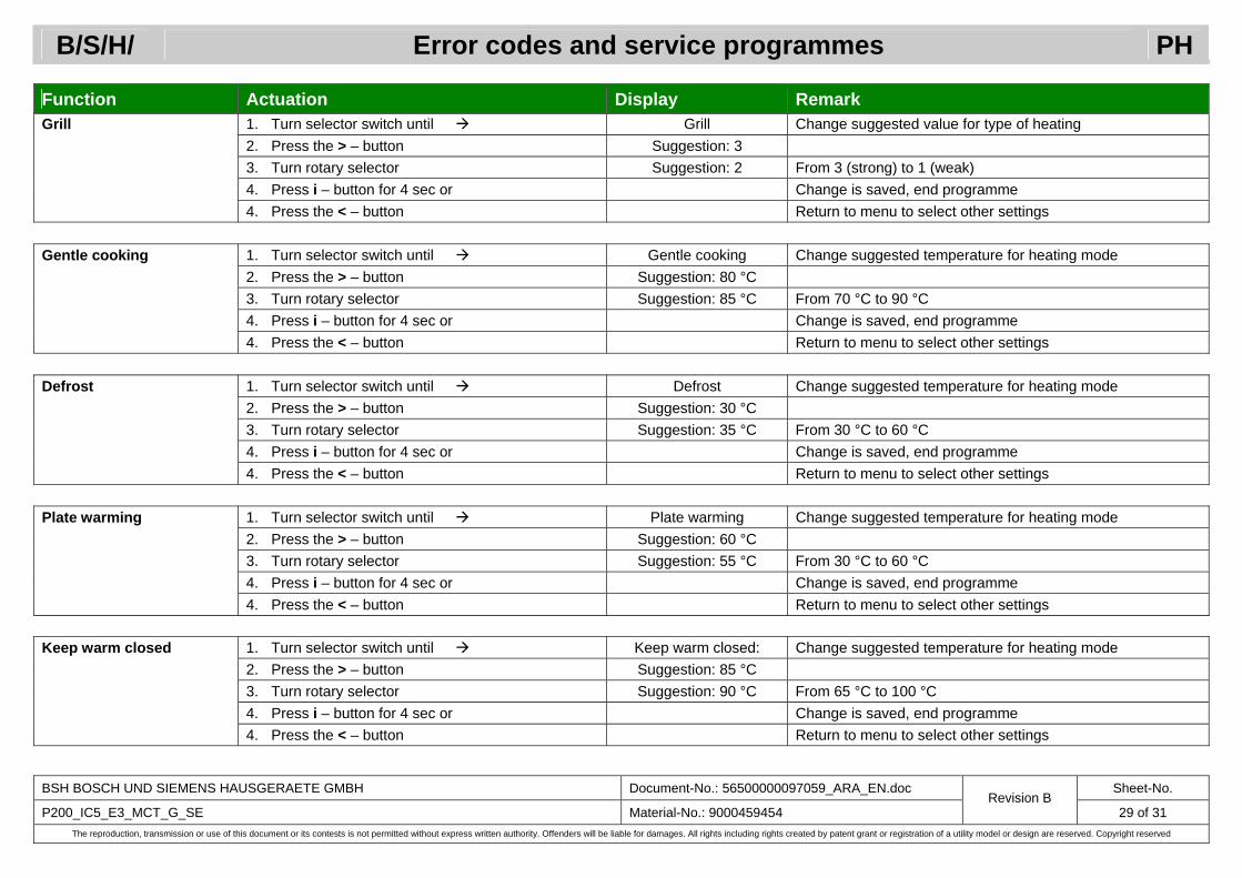
Function Actuation Display Remark Grill 1. Turn selector switch until Grill Change suggested value for type of heating 2. Press the > – button Suggestion: 3 3. Turn rotary selector Suggestion: 2 From 3 (strong) to 1 (weak) 4. Press i – button for 4 sec or Change is saved, end programme 4. Press the < – button Return to menu to select other settings Gentle cooking 1. Turn selector switch until Gentle cooking Change suggested temperature for heating mode 2. Press the > – button Suggestion: 80 °C 3. Turn rotary selector Suggestion: 85 °C From 70 °C to 90 °C 4. Press i – button for 4 sec or Change is saved, end programme 4. Press the < – button Return to menu to select other settings Defrost 1. Turn selector switch until Defrost Change suggested temperature for heating mode 2. Press the > – button Suggestion: 30 °C 3. Turn rotary selector Suggestion: 35 °C From 30 °C to 60 °C 4. Press i – button for 4 sec or Change is saved, end programme 4. Press the < – button Return to menu to select other settings Plate warming 1. Turn selector switch until Plate warming Change suggested temperature for heating mode 2. Press the > – button Suggestion: 60 °C 3. Turn rotary selector Suggestion: 55 °C From 30 °C to 60 °C 4. Press i – button for 4 sec or Change is saved, end programme 4. Press the < – button Return to menu to select other settings Keep warm closed 1. Turn selector switch until Keep warm closed: Change suggested temperature for heating mode 2. Press the > – button Suggestion: 85 °C 3. Turn rotary selector Suggestion: 90 °C From 65 °C to 100 °C 4. Press i – button for 4 sec or Change is saved, end programme 4. Press the < – button Return to menu to select other settings

B/S/H/ Error codes and service programmes PH
BSH BOSCH UND SIEMENS HAUSGERAETE GMBH Document-No.: 56500000097059_ARA_EN.doc Sheet-No.
P200_IC5_E3_MCT_G_SE Material-No.: 9000459454 Revision B
30 of 31 The reproduction, transmission or use of this document or its contests is not permitted without express written authority. Offenders will be liable for damages. All rights including rights created by patent grant or registration of a utility model or design are reserved. Copyright reserved
Function Actuation Display Remark Cooling fan run-on 1. Turn selector switch until Cooling fan run-on: Change duration of run-on time for cooling fan 2. Press the > – button medium 3. Turn rotary selector short From short, medium, long to very long 4. Press i – button for 4 sec or Change is saved, end programme 4. Press the < – button Return to menu to select other settings Speed of the lift 1. Turn selector switch until Speed of the lift: Change travel speed of the lift 2. Press the > – button slow 3. Turn rotary selector quick Slow or fast 4. Press i – button for 4 sec or Change is saved, end programme 4. Press the < – button Return to menu to select other settings Lift moves on: 1. Turn selector switch until Lift moves on: Setting of automatic mode for lift mode (for KI 01 until KI 04) 2. Press the > – button long button press or 3. Turn rotary selector short button press* (* “Short button press” is first step for automatic mode)
4. Press i – button for 4 sec or Change is saved, end programme (automatic mode is not possible until lift end position is saved)
4. Press the < – button Return to menu to select other settings Lift moves on: 1. Turn selector switch until Lift moves on: Setting of automatic mode for lift mode (from KI 05) 2. Press the > – button long button press or 3. Turn rotary selector short button press* (* “Short button press” is first step for automatic mode)
If required, approach required lift end position Appears "Move lift-up floor to end position" message and beep.
4. Save by pressing < – button, or Appears "End position of lift-up floor has been saved" mes-sage and beep. Message remains is on the display until next activity and return to the menu to select of other settings.
4. Press i button for 4 sec Change is saved, end programme

B/S/H/ Error codes and service programmes PH
BSH BOSCH UND SIEMENS HAUSGERAETE GMBH Document-No.: 56500000097059_ARA_EN.doc Sheet-No.
P200_IC5_E3_MCT_G_SE Material-No.: 9000459454 Revision B
31 of 31 The reproduction, transmission or use of this document or its contests is not permitted without express written authority. Offenders will be liable for damages. All rights including rights created by patent grant or registration of a utility model or design are reserved. Copyright reserved
Function Actuation Display Remark Lift end position 1. Turn selector switch until Lift end position (for KI 01 until KI 04) 2. Press the > – button Do not update not applicable KI 05 3. Turn rotary selector Update* If required, approach required lift end position
If required, save by pressing < – button
(* “Update”, then approach the required lift end position and then press < button to save the lift end position (as second step for automatic mode or as lower end position in conjunc-tion with pressing button continuously))
4. Press i – button for 4 sec or Change is saved, end programme 4. Press the < – button Return to menu to select other settings Restore factory settings 1. Turn selector switch until Restore factory settings: Reset changes to standard settings 2. Press the > button No 3. Turn rotary selector Yes No or yes 4. Press i button for 4 sec or Change is saved, end programme 4. Press the < button Return to menu to select other settings