bstj 27: 3. july 1948: the evolution of the quartz crystal
TRANSCRIPT

The Evolution of the Quartz Crystal Clock*
By WARREN A. MARRISON
SOME of the earliest documents in human history relate to man's interest
in timekeeping. This interest arose partly because of his curiosity about
the visible world around him, and partly because the art of time measure-
ment became an increasingly important part of living as the need for cooper-
ation between the members of expanding groups increased. There are still in
existence devices believed to have been made by the Egyptians six thousand
years ago for the purpose of telling time from the stars, and there is good
reason to believe that they were in quite general use by the better educated
people of that period. 1 Since that period there has been a continuous use
and improvement of timekeeping methods and devices, following sometimes
quite independent lines, but developing through a long series of new ideas
and refinements into the very precise means at our disposal today.
The art of timekeeping and time measurement is of very great value, both
from its direct social use in permitting time tables and schedules to be made,
and in its relation to other arts and the sciences in which the measurement
of rate and duration assume ever increasing importance. The early history
of timekeeping was concerned almost entirely with the first of these and for
many centuries the chief purpose of timekeeping devices was to provide
means for the approximate subdivision of the day, particularly of the day-
light hours.
The most obvious events marking the passage of time were the rising and
setting of the sun and its continuous apparent motion from east to west
through the sky. The first practical measure of the position of the sun of
which any record is known was the position or the length of shadows of
fixed objects, resulting through a long period of development in the well-
known sundial in its many forms. But the sundial was in no sense an
instrument of precision and in no sense could be considered as a time keeping
device. Even after the development which resulted in mounting the
gnomon parallel with the axis of the earth, the largest, most elaborate, and
most carefully made instruments could at best indicate local solar time.
Furthermore, the sundial has value only in daylight hours and then only on
* The subject matter of this paper was given before the British Horological Institute in
London on the occasion of the presentation of the Horological Institute's Gold Metal for
1947 to Mr. Marrison in consideration of his contribution toward the development of the
quartz crystal clock. The present text is substantially as published in the Horological
Journal.
510

EVOLUTION OF QUARTZ CRYSTAL CLOCK 511
days when the sun shines clearly enough to cast a shadow. These short-
comings became more and more important with advances in society and,
for measuring duration, man soon began inventing timekeeping means that
would work without benefit of the sun.
The evolution of timekeeping devices may be divided into three main
periods, each employing a specific type of method, although overlapping to
some degree in their applications, and characterized by increasing orders of
accuracy.
A graphical representation of this evolution, indicating these three periods
of development, and showing the relation between some of the major contri-
butions to time keeping and the resulting accuracy of time measurement, is
shown in Fig. 1. The methods employed chiefly during these three periods
may be classified broadly as CONTINUOUS FLOW from the beginning up
until about 1000 A.D., as APERIODIC CONTROL from then until about
1675 A.D. and as RESONANCE CONTROL from that time up to the
present. Keeping in mind the logarithmic nature of the time and accuracy
scales used in this graph, it can be seen readily that most of the advance-
ment has been made in a very small part of the total time, corresponding to
the resonance control epoch.
The Epoch of Continuous Flow
Perhaps due to a feeling that the passage of time was like the flow of some
medium, the first time measuring devices were those depending on the flow
of water into or out of suitable basins. It was recognized that, with an
orifice properly chosen, the time required to fill or empty a given basin should
be about the same on repetition, and hence was born the first reliable means
for measuring time at night or on overcast days. A great variety of devices
operating on this principle were constructed and used, some of the earliest
having been made by the Babylonians and the Egyptians 3500 years ago.
Some of these water clocks, or clepsydra as they were called, had floats
or other indicators which were intended to subdivide a unit of time into
substantially uniform divisions. Others were constructed so that successive
fillings of the basin would be counted or would operate a stepping device,
associated with a dial or other indicator. Through the centuries great
numbers of such devices were constructed, with some of the later ones having
elaborate mechanisms for striking the hours or for animating figures of
people or animals.
For use in places where water was not readily available and where sand
was plentiful, clepsydra were developed that would operate with the flow
of sand in much the same way as with the flow of water. The basic ideas
were not greatly different, the substitution being merely one of expedience.

512 BELL SYSTEM TECHNICAL JOURNAL
ACCURACY IN SECONDS PER DAY
o.0<
•.a
...;. O.
m '. <
o~>
•'•'u.
z 5ou • z
xIs< wCCI
<U. Ill
C>
J
.5aJ2
< r•3
?-*»
rt
I< J,
o toID £

EYOLUTIOX OF QUARTZ CRYSTAL CLOCK 513
The hour glass, and its smaller counterparts, is one of the most convenient
forms of this device and until quite recent times served a useful purpose
where accuracy was of no great importance. The hour glass shown in Fig. 2
was used by a pastor in the early eighteen hundreds to determine the length
of his sermons. The average variation among a set of ten one-hour de-
terminations made recently with this glass was 3 minutes, or about 5 per cent.
The clepsydra that were designed to repeat and totalize an endless succes-
sion of cycles were especially adaptable to the measurement of extended
intervals of time, although with very poor accuracy as we now think of it.
Fig. 2—Hour glass.
By suitable design any desired number of cycles could be made equal to the
natural large unit, the day, so that any fraction of a day within the accuracy
of a given instrument could be determined simply by counting off the
number of cycles from a particular starting point such as sunrise, sunset, or
high noon. It was possible with these devices to operate without calibra-
tion over periods of several days, although the cumulative error inevitably
was very large.
An error of a few hours was of small importance in the days when the
speed of communication and travel alike depended on pack animals or the
caprices of the wind. And so, in spite of the inaccuracies of the water clocks
and sand clocks, they served their purpose well through many centuries.
514 BELL SYSTEM TECHNICAL JOURNAL
In fact, it was not until the tenth century A.D. that any really novel effort
was made to improve upon them as timekeepers. The first efforts to
improve upon them, making use of falling weights for motive power and
various frictional devices to control the rate of fall, were not very successful
because no satisfactory means were known to keep a friction-controlled
device sufficiently constant for the job. Clocks so constructed were no
better timekeepers on the whole than the traditional clepsydra. They had,
however, the hope of compactness, and much ingenuity was exercised in
their design over several centuries.
Also in the category of continuous flow devices should be mentioned the
methods depending on the rate of burning, such as in time candles, time
lamps and their numerous variations. Such timekeepers are not very
accurate but are thoroughly reliable in dry, quiet places, even providing
their own illumination at night. Such timekeepers are known to have been
used before the tenth century A.D. and certain variations still are used by a
few isolated tribes, especially in the tropics.
The Epoch of Aperiodic Control
In or about the year 1360 the invention of an escapement mechanism for
controlling an alternating motion from a steady motive power, such as a
suspended weight, was the first really important step in the history of pre-
cision clock development, and marks the beginning of the second major
epoch in timekeeping evolution. The escapement in one form or another
was soon applied in practically all timekeepers, the most outstanding example
of an early application being a clock constructed by Henry De Vick for
Charles V of France in or about the year 1360 A.D. and still in use—with
extensive modifications—in the Palais de Justice in Paris.
This invention was important, not because De Vick's clock, or any of its
immediate successors, were good timekeepers, but because this was the
first time that vibratory motion in a mechanism was used deliberately to
control the rate of a time-measuring device. All precision clocks depend in
one way or another on using energy to produce vibratory motion, and on
using the rate of that motion to regulate suitable dials and other mechanisms.
No simple improvement on De Vick's clock could ever have produced a
precision clock in the modern sense, however, because the essential rate-
controlling feature was still lacking. His invention consisted of the use of
a verge escapement which produced oscillatory motion in a dynamically
balanced member, known as a foliot balance, having essentially only mo-
ment of inertia and friction. The rate of oscillation, therefore, depended to
a large extent on the applied force exerted by the falling weight through a
train of wheels, and upon the friction of the escapement parts and of the
oscillating member itself.

EVOLUTION OF QUARTZ CRYSTAL CLOCK 515
This sort of operation is known sometimes as relaxation oscillation andappears in many forms. In the clock, the rate-controlling feature dependsupon the length of time it takes a member having a given moment of inertia
to move from one angular position to another under a given applied torque.
Thus, the rate depends to first order on the applied torque.
Although De Yick's clock was one of the most famous in all history, it wasnot because of its good record of timekeeping. In its original form, it is
said that it often varied as much as two hours a day from true time. Out-wardly, this clock on the Palais de Justice appears about the same as it
did originally, but the "works" have been modernized and it keeps muchbetter time now.
The history of timekeeping during the next three hundred years consisted
mainly in improvements and in a great variety of applications of the prin-
ciples contained in De Yick's clock. During this period great numbers of
clocks of all sizes, from tower clocks to portable table clocks were made,controlled by various forms of the crown wheel, verge and foliot balance.
All of these timekeepers belong to the class that we have just called aperiodic.
Their accuracy, in general, was still poor and the indicator on their dials
consisted of but one hand— the hour hand. It was not until the invention
and application of the pendulum that the next major improvement wasborn in timekeeping.
The Epoch of Resonant Control
All that has been said so far is a prelude to the shortest but by far the mostproductive epoch in timekeeping, that of resonant control. The heart of
every precision clock is an oscillatory device which depends upon resonance
for its constancy of rate. The history of precision clock development con-
sists largely of the choice and design of stable resonant elements and of
devising means for using them so that as far as possible their inherent
properties alone control their rates of oscillation. Once in stable oscilla-
tion, it is only necessary to control the indicating of dials and other suitable
mechanisms in order to constitute a complete clock.* Presumably this
can always be done, but in some cases it is more convenient to do than in
others, as will appear.
The resonant element may be any of a wide variety of forms, mechanicalor electrical, all characterized by the single property that, if deformed froma rest condition and released, the stored energy is transformed back andforth from potential to kinetic at a rate depending chiefly on the effective
mass and the effective stiffness, or other like properties, a small proportion
* Encycl. Brit. 14th Ed. "A clock consists of a train of wheels, actuated by a spring orweight or other means, and provided with an oscillating governing device which so regulates(he speed as to render i( uniform."

516 BELL SYSTEM TECHNICAL JOURNAL
of the energy being lost in internal friction at each oscillation. Some
resonant elements which have been used in timekeepers are illustrated in
Fig. 3.
The simplest appearing of all these is that of a mass, M, supported by a
spring with stiffness, S. From the equation of motion
, r d x
ELECTRICAL RESONANTCIRCUIT
QUARTZ RESONATOR
/////A'/////
*9GRAVITY PENDULUM
STieL OR QUARTZTUNING FORK
&TEf=L OR QUARTZ RODIN FLEXURE OR
LONBlTUBINAL VIBRATION
HAIRSPRING ANDBALANCE
fig. 3—Typical resonant elements used in timekeeping,
the period of oscillation may be derived simply and is found to be
T =
Similarly for the simple electrical resonant circuit where current flowing
in an inductance, L, behaves like a mass, and current flowing in a condenser,
C, behaves like the reciprocal of a stiffness, the period may be written.
T = iWLCSimilar expressions are derivable for the periods of oscillation of all simple
oscillating systems, including the pendulum for which the period (for
small amplitudes) is given by
-vl
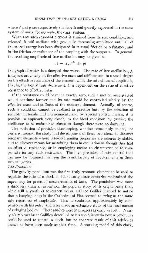
EVOLUTION OF QUARTZ CRYSTAL CLOCK 517
where I and g are respectively the length and gravity expressed in the same
system of units, for example, the c.g.s. system.
When any such resonant element is strained from its rest condition, and
released, it will oscillate with gradually decreasing amplitude until all of
the stored energy has been dissipated in internal friction or resistance, and
in the friction or resistance of the coupling with the supports. In general,
the resulting amplitude of free oscillation may be given as
A = A e~ ' sin pi
the graph of which is a damped sine wave. The rate of free oscillation, p,
is dependent chiefly on the effective mass and stiffness and to a small degree
on the effective resistance of the element, while the rate of loss of amplitude,
that is, the logarithmic decrement, k, is dependent on the ratio of effective
resistance to effective mass.
If the resistance could be made exactly zero, such a motion once started
would continue forever and its rate would be controlled wholly by the
effective mass and stiffness of the resonant element. Actually, of course,
such a condition cannot be realized in practice but, by the selection of
suitable materials and environment, and by special control means, it is
possible to approach very closely to the ideal condition by causing the
oscillation to be maintained almost as though there were no damping.
The evolution of precision timekeeping, whether consciously or not, has
centered around the study and development of these two ideas: to discover
resonant elements whose rate-determining properties are inherently stable,
and to discover means for sustaining them in oscillation as though they had
no effective resistance; or in employing means to circumvent or to com-
pensate for any such resistance. The high precision of rate control that
can now be obtained has been the result largely of developments in these
two categories.
The Pendulum
The gravity pendulum was the first truly resonant element to be used to
regulate the rate of a clock and for nearly three centuries maintained the
supremacy for precision measurements of time. The pendulum was more
a discovery than an invention, the popular story of its origin being that,
while still a youth of seventeen years, Gallileo Galilei chanced to notice
that a hanging lamp in the Cathedral of Pisa seemed to swing at the same
rate regardless of amplitude. This he confirmed approximately by com-
parison with his pulse, and later made an extensive study of the isochronism
of swinging bodies. These studies were in progress as early as 1583. Near-
ly sixty years later Gallileo described to his son Vincenzio how a pendulum
could be used to control a clock, but no concrete result of this advice is
known to have been made at that time. A working model of this clock,

518 BELL SYSTEM TECHNICAL JOURNAL
made subsequently from the original drawings, is on exhibition in the South
Kensington Science Museum, London. The first authentic record of the
actual use of a pendulum in a clock is attributed to the great Dutch scientist,
Christian Huygens, who produced his first pendulum clock in 1657. This
was described by him in the Horologium in 1658.2
The performance of pendulum clocks was so good that almost immedi-
ately clocks of all other types were modified to include a pendulum. So
complete was this transformation that very few unmodified clocks are now
in existence which antedate the first application of the pendulum to time-
keeping. This, as a matter of fact, is one of the major reasons that so
little is known about the actual mechanisms used in mechanical clocks
that were made before the introduction of the pendulum.
The subsequent history of pendulum clock development is well described
in numerous books and papers and covers a wide field. Only those factors
that relate the pendulum to other means of rate control will be discussed in
the following.
The properties of a pendulum which make it such a good timekeeper are
easily seen from a study of the forces on the bob as illustrated in Fig. 3.
Since these forces must be in equilibrium at all times we may write (as-
suming no friction)
Mg sin 6 = Mf—
The nearly isochronous property of the pendulum is contained in this
relationship since the period, on solution, is
where is the maximum semi-amplitude of swing expressed in radians -
When this arc is small the period approaches a minimum. For smal1
angles the natural period depends almost wholly on the ratio of ( to g and
the stability of T depends chiefly upon the constancy of / and g. Figure 4
shows the relation between period and the arc of swing, expressed as seconds
per day departure from the theoretical rate for zero arc.
The sum of all the terms that depend upon powers of sin 0/2 is known as
the circular error, relating to the fact that the bob is constrained to move
on the arc of a circle. It was shown theoretically by Christian Huygens3
that if the bob could be constrained to move on the arc of an epicycloid it
would be truly isochronous, that is, the period would be completely in-
dependent of its amplitude of motion. It is of interest to note at this
point that in no other resonator used for precision timekeeping is there

EVOLUTION OF QUARTZ CRYSTAL CLOCK 519
the direct counterpart of circular error, for in all other cases the restoring
force varies linearly with displacement in the region of operation and not as
a sine function of it.
In the early stages of pendulum clock development it was not necessary
to consider the arc error because other errors were of greater magnitude.
But it is by no means a negligible factor, and in all precision timing bypendulums it must be accounted for, either by allowing for an arc correction,
as is done commonly in geodetic survey work, or by keeping the arc small
and precisely controlling it. According to F. Hope-Jones4, referring to the
master pendulum in the famous Synchronome free-pendulum clock: "Avariation of only 0.01 mm. in the excursion of the bob or 2 sees, of arc will
by circular error alter the rate by 0.00145 sec. per day,—and if it arose un-
16
trw 12Q-
2 iozoH a</)
2 6
zO 4
0.5 1-0 1.5 2.0 2.5LARGEST ANGLE FROM VERTICAL IN DEGREES
Fig. 4—Relation between arc and rate of pendulum.
/
perceived and was steadily maintained, it would produce an accumulated
error of half a second in a year, so the necessity for this close observation
is obvious."
The control of arc has almost invariably been accomplished by keeping
constant the amount of energy applied per swing so that the actual ampli-
tude obtained is that value for which all of the applied energy is dissipated
in the pendulum system. In a sense this method of control of arc puts a
penalty on improvements in design that would reduce the friction, because
the better a pendulum becomes in this respect the less stable becomes the
arc control. Since even the best pendulums develop unexplainable small
changes in arc, it has been common practice in some observatories to record
the arc frequently and to make allowance for changes in it when making
the most precise time determinations.
The inherent constancy of rate of a pendulum, with small or constant
amplitude of swing, depends to the one-half power on the stability of f/g.

520 BELL SYSTEM TECHNICAL JOURNAL
The changes in I and g are quite independent of each other and so can be
treated separately. Other factors that will be described also affect the
rate, and it is the object in every precision clock design to reduce such
variable effects to the absolute minimum.
Some control can be exercised over every factor except g, which remains
a property of space and is dependent only on the proximity of matter and
on acceleration. As is well known, the value of g varies over the surface of
the earth due chiefly to its deviation from spherical shape, and because of
the uneven distribution of matter. It also varies with vertical displacement
or tides at any location to such an extent that a gravity clock that keeps
accurate time at ground level will lose a second a day or more in a tall
building. Actually, it is now possible to chart variations in g with high
precision through measurement of the rate of a pendulum clock against a
standard whose rate does not depend upon gravity.
Most of the factors that can affect I have been studied critically and
means have been found to reduce them to very small effects. The chief
source of variation was at first the temperature coefficient of the pendulum
rod. With ordinary metals the rod expands from 10 to 16 parts in a million
per degree C, causing a proportionate change in rate of half this amount,
corresponding to from one-half to two-thirds of a second per day. Many
ingenious means were developed to reduce this effect, starting with George
Graham's mercury-filled bob in 1721, followed by John Harrison's grid-iron
pendulum in 1726, and a great number of variations on these ideas, all de-
pending on the differential coefficient of expansion of dissimilar materials.
About the year 1895, Charles Edouard Guillaume of Paris developed an
alloy, consisting chiefly of nickel and iron, which he called Invar, because
it had a very small temperature coefficient of expansion, from which pen-
dulum rods could be made. The use of this material made it unnecessary
to resort to complex compensated pendulums with their own inherent insta-
bilities, and the accuracy of timekeeping was increased another step. The
residual temperature effects could be measured readily, and compensated
if desired, by the use of a small bar of aluminum attached to the bob.
Some other important factors that affect the working length of a pendu-
lum are the aging of the supporting rod, the "knife edge" or spring used
for the suspension, the nature of the main supporting column or frame,
and some atmospheric effects caused by changing temperature and pressure.
In the most accurate pendulum clocks, the atmospheric effects are greatly
reduced by mounting the pendulum in partially evacuated, hermetically
sealed enclosures which can be temperature controlled. All of these factors
and many others are discussed in every good treatise on accurate pendulum
clocks. They are mentioned here chiefly for the purpose of comparison
with like factors in the quartz crystal clock and to show how in many

EVOLUTION OF QUARTZ CRYSTAL CLOCK 521
cases the difficulties introduced by such factors may be more easily and
more positively controlled.
In every primary clock mechanism the resonant governing device must
be sustained in oscillation, and the manner in which this is done has a strong
bearing on its rate regardless of the quality of the governing element. Thebasic requirements are the same for any kind of oscillator, whether a pen-
dulum, an electrically resonant circuit comprising inductance and capaci-
tance, a steel tuning fork, or a quartz crystal resonator. The requirements
were first stated for the case of the pendulum by Sir George Airy in 1827 and
it has always been the aim in the design of every good pendulum driving
means to satisfy Airy's condition.
REAL VELOCITY
Fig. 5—Amplitude-phase diagram for resonant element.
This condition is conveniently illustrated by the diagram of Fig. 5 which
shows the two most familiar representations of damped sinusoidal motion.
In order to provide a convenient scale in the drawing an unpractically
large damping is represented, corresponding to a Q of 20. The Q of a
resonant circuit is related to the logarithmic decrement, 8, by the relation
Q8 = ir. The factor 8 is the logarithm, to base e = 2.718 • • •, of the ratio
of the amplitudes at any two successive periods. It should be noted that
the Q of a good electrically resonant circuit is in the order of 200, that of a
good pendulum from 10,000 to 100,000 and that of a good quartz resonator
from 100,000 to 5,000,000. The significance of these higher values of Qwill be evident from the following discussion.
In Fig. 5 the damped sine wave shown corresponds, point by point, to
the phase diagram, which is simply a logarithmic spiral. By suitable choice
of scale the spiral can be interpreted to represent either the amplitude or
the velocity—in which case the real amplitude is vertical and the real
velocity horizontal. In this representation the velocity is shown maximumwhen the amplitude is zero, which is a very close approximation to fact
for all practicable values of Q. The discussion will center on the velocity
spiral.
522 BELL SYSTEM TECHNICAL JOURNAL
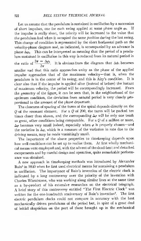
Let us assume that the pendulum is sustained in oscillation by a succession
of short impulses, one for each swing applied at some phase angle <px . If
the impulse is really short, the velocity will be increased to the value that
the pendulum had when it occupied the same position during the last swing.
This change of condition is represented by the short horizontal path on the
velocity-phase diagram and, as indicated, is accompanied by an advance in
phase A^i. This can be interpreted as meaning that the period of a pendu-
lum sustained in oscillation in this way is reduced from its natural period in
the ratio of — —. It is obvious from the diagram that A0i becomes
smaller and that this ratio approaches unity as the phase of the applied
impulse approaches that of the maximum velocity—that is, when the
pendulum is in the center of its swing; and this is Airy's condition. It is
clear also that if the impulse is applied after (instead of before) the instant
of maximum velocity, the period will be correspondingly increased. From
the geometry of the figure, it can be seen that, in the neighborhood of the
optimum condition, the deviation from natural period is very closely pro-
portional to the amount of the phase departure.
The closeness of spacing of the turns of the spiral depends directly on the
Q of the resonant element. For a Q of 200, the turns will be packed ten
times closer than shown, and the corresponding A<p will be only one tenth
as great, other conditions being comparable. For a Q of a million or more,
A<p becomes very small indeed, especially when <p is properly chosen—and
the variation in A<p, which is a measure of the variation in rate due to the
driving means, may be made vanishingly small.
The importance of the above properties to timekeeping depends upon
how well conditions can be set up to realize them. At first wholly mechani-
cal means were employed and, with the advent of the dead-beat and detached
escapements and by careful design and operation, quite remarkable perform-
ance was obtained.
A new approach in timekeeping methods was introduced by Alexander
Bain5 in 1840 when he first used electrical means for sustaining a pendulum
in oscillation. The importance of Bain's invention of the electric clock is
indicated by a long controversy over the priority of the invention with
Charles Wheatstone, who was working along similar lines at the same time
as a by-product of his extensive researches on the electrical telegraph.
A brief story of this controversy entitled "The First Electric Clock" was
written for the one-hundredth anniversary of Bain's invention6. The first
electric pendulum clocks could not compare in accuracy with the best
mechanically driven pendulums of the period but, in spite of a great deal
of initial skepticism on the part of those brought up in the mechanical

EVOLUTION OF QUARTZ CRYSTAL CLOCK 523
tradition, electrical maintenance and control has been applied in the most
accurate pendulums in the world.
The free-pendulum clock makes use of the idea, first proposed by Rudd,
of allowing a master pendulum to swing free of all sustaining or other
mechanism for a considerable number of periods and of imparting to it,
after each group of free swings, a single impulse large enough to maintain
the next equal number. The advantage is that no friction effects of driving
mechanism are coupled to the pendulum except during that minimum time
required to impart energy to it. Actually, in theory, the phase error
introduced by one large impulse after n free swings is exactly the same as
the sum of the phase errors for n small impulses. That can be deduced
from the phase diagram of Fig. 5. But experience has shown that a pen-
dulum is actually more stable when the sustaining mechanism is detached
from it the greater part of the time.
The Synchronome free-pendulum clock includes also the basic idea of
the gravity remontoir first applied by Lord Grimthorp (then Sir Edmund
Beckett Denison) in the design of the mechanism of Big Ben, London,
constructed in 1854—and still in continuous operation. The ingenious
application of these principles and the electrical means devised by F. Hope-
Jones and W. H. Shortt for its accomplishment have resulted in the con-
struction of the most accurate pendulum clocks in the world by the Syn-
chronome Clock Company of London. The history and development of
the free-pendulum clock is elegantly described by F. Hope-Jones in his book
on Electric Clocks7.
The predominant characteristics of a pendulum resonator, as used in a
clock, have just been discussed in order to show the parallel between them
and the properties of other resonant systems. It will be shown how some
of the factors that have been troublesome in the development of pendulums
have been rather easily taken account of in other types of control devices
and in particular in the quartz crystal clock.
The Evolution of Electric Oscillator Clocks
It almost never happens that a result of any considerable value is obtained
at a single stroke or comes through the efforts of a single person. More
often even the most important advances come as the climax of a long series
of ideas which have accumulated over a period of years until the next step
becomes almost self-evident and is accomplished either through the necessity
for a new result or as a logical next step.
This was preeminently the case in the crystal clock development and
involved the putting together of a considerable number of ideas that had
been accumulating through a century or more of related activity. The
524 BELL SYSTEM TECHNICAL JOURNAL
chain of events which led eventually to the crystal clock followed a course
quite independent of pendulum clock development, although parallel with
it, and meeting it from time to time on the way. From the start, it in-
volved the use of resonant elements whose frequencies do not depend upon
gravity for controlling the frequency of oscillations in a positive feedback
amplifier. From a rather simple beginning, taking advantage of a series of
discoveries and inventions through about a century of progress, there has
evolved a clock whose stability is comparable with that of astronomical
time itself, as heretofore defined in terms of the earth's rotation, and having
a versatility far exceeding all other existing means for the precision measure-
ment of time.
Electric Oscillators
The first recorded experiments that relate directly to this development
were those of Jules Lissajous8 who, in 1857, showed that a tuning fork can
be sustained in vibration indefinitely by electrical means, using an electro-
magnet and an interrupter supported by one of the prongs. The idea of
using an interrupter to sustain vibration was not new with Lissajous, but
had been invented by C. G. Page9 and described by him as early as April
1837, to obtain a regularly interrupted electric current. Credit for this
important invention is often given to Golding Bird10 or Neeff 11 who evidently
were working along similar lines concurrently although quite independently
of each other. Page, Golding Bird and Neeff were all medical doctors and
evidently were interested in their devices more for their therapeutic interest
than for the general scientific value, since "galvanic" electricity was at-
tributed at that time with marvelous healing powers.
Lissajous was probably the first to make use of the idea for accurate
measurements of rate, being a prolific experimenter in mechanics and
acoustics, and the originator of the famous method bearing his name for
the study of periodic motions. Indeed, the electrically operated fork was
developed especially for use as a standard to be used in studying the rates
of other vibrators. In principle, the electrically operated fork is like the
pendulum drive of Alexander Bain, except that the rate of vibration in this
case is not a function of gravity but for the most part is controlled by the
effective mass and elastic stiffness of the vibrating member.
The tuning fork itself was invented in 1711 by John Shore, a trumpeter in
Handel's orchestra 12, and was developed to a high state of perfection by
the great instrument maker and physicist of Paris, Rudolph Konig. To
establish an accurate standard of pitch for calibrating these forks Konig
developed what he termed an "absolute" method for the determination of
frequency. This consisted of a tuning fork having a frequency of 64 vibra-
EVOLUTION OF QUARTZ CRYSTAL CLOCK 525
lions per second, with delicate mechanical means, similar to a clock escape-
ment, for sustaining the fork in vibration and for counting the number of
vibrations over any desired interval of time. For this purpose, the escape-
ment mechanism was geared to the hands of a clock, so that when the fork
had its nominal frequency the clock would keep correct time. Dr. Konig
credits the invention of the fork-clock to N. Niaudet 13in these words:
"Cette disposition avail 6t6 realises pour la premiere fois dans l'horloge a diapasonque N. Niaudet fit presenter a I'Academie des Sciences le 10 decern bre 1866, et que a figureaux e:q:>ositions universelles dc Paris 1867 et de Vienne 1873."*
Thus, as early as 1866, the essential elements had been developed sepa-
rately from which a clock of the electric oscillator type could have been
constructed. But it was not until more than half a century later, whenthere was more apparent need for such a clock, that it was actually realized.
It was chiefly for the purpose of studying temperature coefficients and like
properties of tuning forks that Konig constructed and used his famous
mechanical fork-clock. There is no evidence that there was at that time
any idea of using a fork-clock as a timekeeper.
It was for the purpose of making still more precise studies of the properties
of tuning forks that H. M. Dadourian 11 in 1919 made use of the phonic
wheel motor for the first time for counting the number of cycles executed by
a fork over an extended period of time to measure its rate. By means of a
chronograph the time interval corresponding to the total of a very large
number of periods could be measured precisely in terms of a standard clock,
thus providing a direct "absolute" measure of fork rate. For this he found
already invented for him all of the essential component parts, including
the fork with electromagnetic drive, and the phonic wheel motor.
The phonic wheel motor, which in some modified form is an essential
part of nearly all oscillator clocks, was invented by two investigators,
apparently quite independently and for entirely different purposes. Thefirst published reports of each appeared in 1878.
The first of these is an American patent that was granted on May 7,
1878 to Poul La Cour 15, a Danish telegraph engineer. The application was
filed in Washington on April 9 of the same year, and described a fork-
controlled impulse motor similar to those still used in many modern syn-
chronous clocks. The other publication was a report in Nature for May 23
of the March 30 Physical Society Meeting. In this, Lord Rayleigh de-
scribed a motor which he developed to measure the frequency of sound by a
stroboscopic method. 16 Both of these original disclosures indicated a
* "This apparatus was realized for the first time in the fork-clock which N. Niaudetdescribed at the Academy of Sciences on December 10, 1866, and which was shown at theexpositions of the University of Paris in 1867 and the University of Vienna in 1873."

526 BELL SYSTEM TECHNICAL JOURNAL
considerable amount of previous study, even including the fluid-filled
flywheel to reduce hunting. It may be impossible at this time to know who
actually put in motion the first phonic wheel motor.
Difficulties inherent to contact-controlled devices prevented the develop-
ment of highly accurate fork standards of this type, and there is no evidence
so far that any thought had been given to the use of a tuning fork as a
timekeeper.
The method of using a microphone instead of a contact was proposed by
A. and V. Guillet 17, in 1900 and has been used considerably in frequency
standards of moderate accuracy, but that too had limitations which made
it impossible to utilize fully the inherent stability of a good tuning fork.
The Use of Vacuum Tubes
The first opportunity for really precise control of the frequency of a
mechanical vibrating system, and the next step in the oscillator clock
evolution, came with the invention of the thermionic vacuum tube at the
turn of the century. The development of the vacuum tube has been a more
or less continuous process18 starting with the studies of electrical conduction
in the neighborhood of hot bodies by Elster and Geitel, Edison, and Fleming,
and later developed into the first practical devices by Fleming19 and
DeForest2 *1 in England and America respectively. The first patent for
such a device, a two-element tube, was issued to J. A. Fleming in 1904.-'
The first patent on a tube containing three elements and suitable for use as
an amplifier was issued to Lee DeForest in 1907.22
The vacuum tube as an amplifier found almost immediate and widespread
application in telephony and, next to the basic telephone elements, was the
most important single factor contributing to long distance communication.
For this purpose large amounts of amplification were required. Very
often in the operation of early amplifiers, enough signal from the output
would somehow get coupled into the input circuit to make the entire circuit
break into oscillation on its own account at some frequency for which the
amplifier and feedback circuit were particularly efficient.
Although this was very annoying in an amplifier, it led naturally in 1912
to the invention of the vacuum tube oscillator, consisting essentially of an
amplifier with coupling between the output and the input and some definite
means for regulating the frequency of oscillation. The first to seek patent
protection in vacuum tube oscillators were Siegmund Strauss23 in Austria,
Marconi Company in England24,A. Meissner in Germany, and Irving
Langmuir, E. H. Armstrong and Lee DeForest25 in America. Many specific
forms have since been invented and widely used, some of the more familiar
types being associated with the names of Colpitis, Hartley and Meissner.

EVOLUTION Of QUARTZ CRYSTAL CLOCK 527
With the vacuum tube oscillator controlled by electric circuit elements,
it would have been possible immediately to operate a clock by means of a
phonic wheel motor. Even if this had been done, however, the accuracy
would not have compared very favorably with that of good mechanical
clocks of the period. This is because the rate-controlling element of such
oscillators was subject to large changes due to temperature and aging, and
because means were not yet known for avoiding the effects of tube and other
variables on the resulting frequency.
The next important step in our evolution was the use of the vacuum
tube to sustain the vibration of a tuning fork. This may be considered
either as an improvement on the contact-driven fork by the substitution of
a vacuum tube relay device instead of the contact, or as an improvement on
the vacuum tube oscillator by the substitution of a mechanical resonator
for the electrical resonant element. This achievement was first announced
by Professor W. H. Eccles26in April or May, 1919, and was followed on
June 20 by a note by Eccles and Jordan27 in the London Electrician. Mean-
while, on June 16 of the same year, a similar announcement appeared in
Comptes Rendus by Henri Abraham and Eugene Block2*, showing that
parallel developments were in progress in both England and France. How-
ever, Eccles and Jordan in discussing their work at the National Physical
Laboratory stated: "Several instruments of this kind have been set up and
used during the past 18 months." From this, we may imply that they had
vacuum tube driven forks in operation early in 1918.
One of the chief advantages of the use of the vacuum tube to sustain
oscillations in a mechanical system is that the variable friction of the contact
mechanism is avoided. Previously this had been one of the main causes of
instability. With the new method it became possible to operate in a wide
frequency range, continuously, and at small amplitude, and to deliver
alternating currents of approximately sine wave form and having more
constant frequency than heretofore had been possible. The judicious use
of a vacuum tube in delivering power to sustain the vibration of a resonator
is analogous to the ideal of the so-called free pendulum but may be utilized
more effectively in freeing the resonator from disturbing influences associated
with the driving means.
Another important advantage, which, however, was not realized im-
mediately, is the ease with which the phase of the driving force applied to
a mechanical vibrator can be adjusted for greatest frequency stability.
In a manner analogous to the pendulum, in which it was shown that the
rate is least affected when the driving impulse is applied at the instant of
maximum velocity, the current delivered to the driving electromagnet and
hence the force applied to the vibrating element, should be in phase with

528 BELL SYSTEM TECHNICAL JOURNAL
the velocity of that element. In the vacuum tube oscillator, it is a relatively
simple matter to design the feedback circuits to meet this condition very
accurately.
In 1921 and 1922 Eckhardt, Karcher and Keiser29 - 30 described the
development of a precise fork and vacuum tube driving means, pointing
out the following uses: "As a sound source; as a small scale time standard;
as a current interrupter; as a synchronizer." The chief emphasis seems to
have been on the second item because in the same year Eckhardt described
a high-speed oscillograph camera using the same fork as a precise timing
device. The study and improvement of the tuning fork oscillator were
carried on continuously and soon such oscillators were used in several
national physical laboratories and commercial research institutions as stand-
ards of frequency and time interval.
The next two reports of progress appeared in 1923, one by D. W. Dye
of the National Physical Laboratory in Teddington, and the other by J. W.
Horton, N. H. Ricker and W. A. Marrison of Bell Telephone Laboratories,
New York City. Both of these papers disclosed work done over a period
of two or three years and described apparatus that had been in operation
for a considerable period. Dr. Dye employed a 1000-cycle steel tuning
fork and a phonic wheel motor operating synchronously from it with a
gear reduction and cam to produce periodic electrical signals which he
compared with a clock by means of a chronograph31. Horton, Ricker, and
Marrison used a 100-cycle steel fork, a synchronous motor with a gear
reduction to produce electrical impulses at one-second intervals, and a
clock mechanism operating directly from these signals32. This appears to
be the first time that a vacuum tube-controlled oscillator was ever used to
operate a complete clock mechanism. Shortly thereafter, a clock was built
in which the 100-cycle motor was geared directly to the clock mechanism
instead of operating through a stepping device. A contacting device was
retained, however, for the purpose of making precise time measurements.
For precise measurements of rate over long time intervals, means were
provided to compare the seconds pulses controlled by the synchronous
motor directly with time signals received by radio from the Naval Observa-
tory. To facilitate these comparisons, a two-pen siphon recorder was built
by means of which the time marks were laid down side by side on a moving
strip of paper in such a way that accurate subdivisions of a second could be
made on any part of the record.
This same two-pen recorder and 100-cycle fork time standard was used
during the total solar eclipse of January 24, 1925 to time the progress of
the moon's shadow as observed at a number of stations in the path which
were all connected by a round-robin telegraph circuit, through the Bell

EVOLUTION OF QUARTZ CRYSTAL CLOCK 529
Telephone Laboratories' headquarters in New York City 33'34
. A photo-
graph of the original records is reproduced in Fig. 6. This is believed to be
the first time that a vacuum tube oscillator type of time standard was ever
used in the service of astronomy.
During the following ten years a great number of improvements were
made in tuning fork oscillators and they became widely used as precise
frequency standards. The Bell Laboratories' 100-cycle fork standard was
mounted in a container which could be sealed at constant pressure or vac-
uum. It was carefully temperature controlled and provision was made to
keep the amplitude within prescribed limits. In describing this improved
standard35, comprising a synchronous motor geared directly to a clock
mechanism, the authors Horton and Marrison made the following statement
:
"During tests on this frequency standard, it was found that it constituted a far morereliable timekeeper than the electrically maintained pendulum clock which was used to
obtain the data already published. The pendulum clock was, therefore, dispensed with
and all measurements of the rate of the fork are now made by direct comparison with the
mean solar day as defined by the radio time signals sent out by the U. S. NavalObservatory."
In all fairness to the pendulum clock in question, it should be stated that
the laboratory was situated on the seventh floor of a building adjoining a
busy street and so was continually subject to vibration from traffic, wind,
and other changing conditions. Disturbances of this sort have little or no
effect on standards of the electric oscillator type but seriously impair the
performance of most high precision pendulum clocks. The relative im-
munity of the oscillator standard to change of position and shock has an
important bearing on its value in many applications.
Probably the most precise tuning fork controlled time and frequency
standards ever constructed were those developed in the National Physical
Laboratory at Teddington, as a continuation of the work begun there by
Professor Eccles and carried forward by Dr. Dye and his staff. A report
by D. W. Dye and L. Essen in the Royal Society Proceedings in 19343G
described a number of refinements in the fork and method of use some of
which had been suggested by Dr. Dye as a result of his studies ten years
earlier. Among these was the use of elinvar in the construction of the forks
in order to reduce the effect of variable temperature on the frequency.
Elinvar is a nickel steel containing about twelve per cent of chromium,
which on proper treatment has a small or zero temperature coefficient of
elasticity. It was invented by Charles Edouard Guillaume37'38 and was
further studied by P. Chdvenard89, ,u. The excellence of the N.P.L. fork
standard can be appreciated readily from the conclusion of the 1934 report
which states in part:

F>M) BELL SYSTEM TECHNICAL JOURNAL
f 1 8I'
sM- y;
\
B8
i r'
j.
I'
a r r«
.
t ri
» b
5 ri
i •A
. ~ & k' 5 4
r5 a l
fc
4
rI ? ,
jj
is
*SO
V > *
©^
3
1o-J
' 5
1 •
1 £
*
5 Mr b
•
(ft1- - "J
en
u :*3
L
1
r r*lUl
rc
\ *t 1
, $ * j,;
Vr-
i I ! F \ '

EVOLUTION 0I; (HARTZ CRYSTAL CLOCK 531
"The frequency of the fork in comparison with the N.P.L. Short t clock can he measuredat any time with an accuracy of 5 parts in 10 8
. It is necessary to apply a correction forthe rate of the Shortt clock, and the ultimate accuracy with which the absolute value of
frequency is known de[)ends on the accuracy of the time signals which are used to determinethe rate of the clock. The final frequency can, however, usually he ascertained with anaccuracy of ±1.5 parts in 107
. In its present condition the tuning fork maintains afrequency stability of the order of .* parts in 107 over periods of a week or more."
A considerable amount of effort has been devoted to the improvement of
tuning forks, directed mostly toward stabilizing the fork itself. Patents
issued to H. H. Hagland", August Karolus 1 - and Bert Eiscnhour 111 have been
concerned with the reduction of temperature coefficient by various methods
of compensation in the alloy or in the mechanical structure of the fork. In
recent years, alloys have been produced from which forks with a zero coeffi-
cient of frequency can be machined. These alloys have neither a zero ex-
pansion coefficient nor a zero elastic coefficient, but the two coefficients are
so balanced that their effects cancel as they concern I he frequency of a
tuning fork.
One of the largest residual sources of error in a good fork is that caused by
the coupling through the mounting. A fork which is efficient as a producer
of sound by coupling through the base would be quite useless as a precise
standard of rate due to the losses introduced in this manner. It has been
shown by S. K. Michaels44 that the tines of a well-balanced fork can be so
shaped that practically no energy at fundamental frequency is transmitted
through the base.
By making use of all that is known about materials, shapes and mountings
for tuning forks, and all that is known about stabilized vacuum tube cir-
cuits for driving them, it is quite possible that considerable further improve-
ment could now be obtained in such a standard. But another line of
development has shown greater promise in this field and the ultimate
accuracy of tuning fork oscillators has never been pursued.
The Quart: Resonator
During the same ten years that the greatest advances were being madein the tuning fork art, the striking properties of the quartz crystal resonator
were reviewed and first applied in the construction of frequency and time
standards. Its use in primary standards for the most exacting measure-
ments of frequency and time is now almost universal in national and indus-
trial laboratories throughout the world.
Quartz crystal is the most abundant crystalline form of silicon dioxide,
occurring, in some parts of the world, in large single crystals from which
mechanical resonators of useful dimensions can readily be formed. Thephysical properties that make it eminently suitable for use in a standard of
rate or time are its great mechanical and chemical stability. Having a

532 BELL .SYSTEM TECHNICAL JOURNAL
hardness nearly equal to that of ruby and sapphire, and a rigidity of structure
such that it cannot be deformed beyond its elastic limit without fracture,
it might be expected to remain in a given shape indefinitely under ordinary
conditions of use. Because of its great chemical stability, its composition
is not easily modified by any ordinary environment.
In addition to its inherent physical and chemical stability, the elastic
hysteresis in quartz is extremely small. For this reason, it requires only a
very small amount of energy to sustain oscillation and the period is only
very slightly affected by variable external conditions in the means for
driving it.
A striking illustration of the importance of this property is indicated by
the number of periods that a resonant element will execute freely, that is,
without any sustaining forces whatever, during the time required for the
amplitude to decrease to one-half of some prescribed value. For a good
electrical circuit consisting of an air core inductance and an air condenser,
this number is about 100; for a good tuning fork in vacuum, it is about 20C0.
For a good cavity resonator under standard conditions of temperature and
pressure, the number may be as high as 10,000. The best gravity pendu-
lums will swing freely from 2,000 to 20,000 times before they reach half
amplitude. The effect is most striking of all in quartz crystal, in which the
internal losses are extremely low. Professor Van Dyke has measured the
rate of decay of oscillations under a wide range of conditions45 and has found
that, as ordinarily mounted, nearly all of the losses are in the mounting or
in the surrounding atmosphere, if any, or in surface effects. Extremely small
amounts of surface contamination will more than double the decrement.
Recently46 Maynard Waltz and K. S. Van Dyke have measured the decre-
ment of one out of the first set of four zero coefficient ring crystals ever made47
and found that, vibrating freely in vacuum and favorably mounted, it would
execute more than a million vibrations before falling to half amplitude.
The advantage of this property is immediately obvious because of the
relatively small amount of energy that must be supplied at each oscillation
to keep the resonator in motion. As already discussed in relation to the
pendulum, the amount that the rate of oscillation may be disturbed in a
given structure is proportional to this energy and, to first order, on the
departure from the ideal phase condition of the applied driving force.
The properties just enumerated are sufficient to assure the superiority of
quartz crystal for the control element in a rate standard; no other vibrating
system known at the present time is so sharply resonant or so stable. How-
ever, one more property, its piezoelectric activity, has added greatly to the
convenience of its use in vacuum tube devices.
The piezoelectric effect was discovered by the Curie brothers in 1880,48

EVOLUTION OF QUARTZ CRYSTAL CLOCK 533
and in the years following was studied extensively by them4950 . They
found that when quartz and certain other crystals are stressed, an electric
potential is induced in nearby conductors and, conversely, that when such
crystals are placed in an electric field, they are deformed a small amount
proportional to the strength and polarity of that held. The first of these
effects is known as the direct piezoelectric effect and the latter as the inverse
effect. The amount of such deformation in quartz is extremely minute, a
static potential gradient of 1 esu (300 volts) per centimeter causing a
maximum extension or contraction, depending on the polarity, of only
6.8 X 10_s cm per cm. If a crystal resonator is subjected to an alternating
electric field having the frequency for which the crystal is resonant, the
amplitude of motion will, of course, be multiplied many times. In prac-
tice, however, the actual amplitudes of motion are kept so small, by limiting
the applied electric field, that even with the largest crystals used they can
OMbJUJjf 25w O.0288////f 420w
—1(
—
okrp—vw—
I
i—1(
—
r^^—vw—
i
17 H 1026 H
GT CRYSTAL UNIT SQUARE ROD, 8.3 x 0.5 X 0.5 CMFREQUENCY 100 KC FREQUENCY 29.2 KC
Fig. 7—Equivalent electrical circuits for typical quartz crystal resonators.
be observed only under a high powered microscope. This, in conjunction
with means for precise amplitude control, is one of the reasons for the
remarkable frequency stability of quartz crystal oscillators.
In practice, a quartz resonator is mounted between conducting electrodes
which now most often consist of thin metallic coatings deposited on the
surface of the crystal by evaporation, chemical deposition or other suitable
means. Electrical connection is made to these coatings through leads
which also support the crystal mechanically. The resonators with which
we are chiefly concerned in this discussion have only two electrodes.
If such a two-terminal resonator is connected into any circuit, it will
behave there as though it consisted of wholly electrical circuit elements,
usually of such low loss as can not be realized by other means. The equiv-
alent electric circuit for a quartz crystal resonator was first described51 by
K. S. Van Dyke in 1925 and, for some significant cases, is illustrated in
Fig. 7. The part of such an equivalent circuit which in many cases cannot
be duplicated by any ordinary means is the inductance element containing
so little resistance. It is as though an electric resonator could be made and
utilized constructed of some supra-conducting material.

534 BELL SYSTEM TECHNICAL JOURNAL
Among the first serious efforts to utilize the piezoelectric effect in electrical
circuits were those of Alexander McLean Nicolson who used rochelle salt
crystal in the construction of devices for the conversion of electrical energy
into sound and vice versa. He constructed loudspeakers and microphones
during several years of study prior to the publication of his work52 in
1919—ideas now being used extensively in phonograph pickups, micro-
phones and sound producers. Nicolson also was the first to use a piezo-
active crystal to control the frequency of an oscillator. His patent53,
applied for in 1918, shows a circuit which he operated successfully in 1917.
The first actual use of resonators of quartz is attributed to P. Langevin54•
55,
who drove large crystals in resonance in order to generate high-frequency
sound waves in water for submarine signaling and depth sounding.
The Quartz Crystal Controlled Oscillator
The first comprehensive study of the use of quartz crystal resonators
to control the frequency of vacuum tube oscillators was made by Walter G.
Cady in 1921 and published by him in April, 192256. This was the step
which initiated a most extensive and intensive research of the properties of
quartz crystal and into methods for its use in numerous fields requiring a
stable frequency characteristic.
The extent and importance of this research are well indicated by the
number of investigators and published contributions to the art. Among
these, a paper by A. Scheibe" in 1926 lists 28 articles on the subject, along
with a description of his own extensive studies. Two years later Cady
published a bibliography58 on the subject, including 229 separate references
to papers and books and 84 patents in various countries. R. Bechmann in
1936 published a review of the quartz oscillator59 including 26 references to
other original contributions in that field alone. More recently there comes
at the end of Cady's 1946 book60 on "Piezoelectricity", a bibliography of
57 books and 602 separate published articles on this subject. By any
measure this represents a great amount of detailed effort for a single subject
in so short a time—just about a quarter of a century. Of this great amount
of material, it is feasible to review only a small number of the outstanding
ideas relative to the evolution of the quartz crystal clock.
The first published quartz-controlled oscillator circuit is reproduced in
Fig. 8A from Cady's 1922 article. In this oscillator the "direct" and
"inverse" piezoelectric effects were employed separately, making use of
two separate pairs of electrodes. The output of a three-stage amplifier
was used to drive a rod-shaped crystal at its natural frequency through
one pair of electrodes making use of the "inverse" effect, while the input to
the amplifier was provided through the "direct" effect from the other pair.

EVOLUTION OF QUARTZ CRYSTAL CLOCK 535
The feedback to sustain oscillations in the electrical circuit could be obtained
only through the vibration of the quartz rod and hence was precisely con-
trolled by it. Cady's results were received with widespread interest and
were duplicated and continued in many laboratories, which soon resulted
in many new discoveries and inventions.
(3) EARLIEST QUARTZ OSCILLATOR, BWALTER G. CADY, 1921
f!
r Tf(b) PIERCE AND PIERCE -MILLER OSCILLATORS
(C) BRIDGE STABILIZED OSCILLATOR, L.A.MEACHAM
lug. 8—Typical quartz oscillator circuits.
Important contributions were made by G. W. Pierce, who, showed in the
following year that plates of quartz cut in a certain way could be made to
vibrate so as to control frequencies proportional to their thickness61 . Healso proposed somewhat simplified circuits for their use which soon found
very general application in the construction of wavemeter standards and
later for oscillators used to control the frequency of broadcasting stations
and for many other purposes. In 1924, the General Radio Company of
Cambridge, Massachusetts, produced a commercial instrument based on
these studies.

536 BELL SYSTEM TECHNICAL JOURNAL
The significance of the unusually stable properties of quartz crystal—
which at times were viewed with a sort of awe and a tendency at first to
expect too much62 "—was soon recognized in relation to precise standards
of frequency and time, and many laboratories made experiments directed
toward these applications.
For some years these efforts usually took one of two forms: either that of
a quartz-controlled oscillator used as a comparison standard by various
means03, or that of using the quartz resonator itself as a portable standard,
the high-frequency counterpart of an isolated tuning fork. Probably the
most convenient standards of the latter sort were the luminous resonators
first described in 1925 by Giebe and Scheibe61. The following year they
proposed the use of such luminous resonators as frequency standards65 and,
shortly following, portable frequency indicators of this sort were made
available for general use. The use of such a luminous resonator for the
international comparison of frequency standards was reported by S. Jimbo
in 1930.M The first international comparison of frequency standards
making use of piezo resonators as isolated standards was carried out by
Walter (i. Cady in 1923, who by means of a set of early type resonators com-
pared the existing standards at Rome, Livorno, Paris, Teddington, Farn-
borough, Washington, and Cruft Laboratory at Harvard University67.
In the following year the U. S. Bureau of Standards carried out a similar
international frequency comparison, but of greater accuracy,* employing
portable quartz crystal oscillators. This comparison and other important
related studies were described by J. H. Dellinger in 1928—"The Status of
Frequency Standardization"68.
It was soon recognized that quartz oscillators could be built with a
stability far greater than that of any other known type and that they possess
qualities very desirable for a combined time and frequency standard.
However, all early quartz oscillators had frequencies far too high to operate
any synchronous motor and it was not immediately obvious how a clock
could be operated thereby.
The Frequency Divider
The illustration in Fig. 9 from the author's notebook for November, 1924
is believed to be among the earliest means proposed to accomplish this.
In brief, the proposal was to control the speed of a motor driving a high-
frequency generator so that a harmonic of the generator output, say the
* In 1929, M. G. Siadbei wrote "Nous pensons que lc quartz piecoelectrique peut
(rouver un nouvel emploi dans la chronomelrie, Slant donnee la conservation rigoureuse-
ment constant dc ses oscillations."
"La seul cause de variation de la periode d'oscillation rdsulte en effect du changement de
la temperature. . ..'

EVOLIT/OX OF OLARTZ CRYSTAL CLOCK 537
tenth, would have a frequency of the same order as that of the crystal but
differing from it by a relatively low frequency, }\. This low frequency,
derived from the modulator was to be used to drive the synchronous motor.
DATE"~7Uv*>*^** /£~ /rzY.
55
/ j 7- ^
.
7-
_- ^Or*»U. ^i*^6-0t%+S ?M*±^.ZjfiM jS yZ^^ n̂^.t^t r^f rf -?.
^if 0C4*f C*n*r<4t.c&ti4
nt~4i -a^t.1 "./.< isi- •
Fig. 9—Early suggestion of means to control a rotating device such as a clock from ahigh frequency.
The shaft speed of the motor-generator would, therefore, be integrally
related to the crystal frequency and hence any mechanism geared to the
shaft, such as a clock, would indicate time as dictated by the crystal. This
method could have been carried through readily by a combination of means
already developed for other purposes, and the construction of an apparatus
based on this suggestion was soon begun. However, a simpler method 6 **,

538 BELL SYSTEM TECHNICAL JOURNAL
not involving a rotating machine in the control system, was suggested and
the first quartz crystal clock was constructed using the simpler means.
This apparatus was described by Horton and Marrison 7" before the Interna-
tional Union of Scientific Radio Telegraphy in October, 1927. The reso-
' 1 1 1 -
Fig. 10— 50,000-Cycle quartz resonator, in original mounting, used in first quartz
clock— 1027.
CONTROLLEDLOW-FREQ.OUTPUT
Fig. 11—Submultiple controlled frequency generator used in first quartz clock.
nator in its mounting that was used in this first model is shown in Fig. 10.
It consisted of a rectangular block of crystal, cut in the manner usually
called X-cut, and of such size as to oscillate at a frequency of 50,000 cycles
per second in the direction of its length. The temperature coefficient of
this resonator was approximately 4 parts in a million per degree C at the

EVOLUTION OF QUARTZ CRYSTAL CLOCK 539
temperature of operation, which was controlled at a value in the neighbor-
hood of 40 degrees (\
The method for frequency subdivision used in this first quartz crystal
clock, is illustrated in Fig. 11. The inductance element of an electric circuit
oscillator, designed to operate at the desired low frequency, has a core of
variable permeability so that the frequency can be adjusted over a narrow
range through the control of direct current in an auxiliary winding. Aharmonic of this low frequency, generated in the tube following the oscil-
lator, is compared with the incoming high frequency in the vacuum tube
modulator. The harmonic chosen has nominally the same frequency as
that of the control, or crystal oscillator, so that one output of the modulatoris a direct current whose magnitude and sign vary with the phase relation
between the inputs to the modulator. The use of this method to regulate
the low-frequency oscillator insures that the low frequency is some exact
simple fraction of the high frequency. If, therefore, a synchronous motoris operated from the low frequency thus produced, its rate represents ac-
curately that of the high-frequency source as though it had been possible to
use that source directly.
Several other electrical circuits were proposal around 1927 for the sub-
division of high frequencies. The method in most general use at present is
an adaptation of the "multivibrator" first used by Henri Abraham andEugene Block in 1919 for the measurement of high frequencies71
. Theyused their circuit to produce a wave rich in harmonics and having a funda-
mental that could be compared directly with that of a tuning fork standard.
By various means now well known the high frequency could be comparedwith one of the harmonics of this special oscillator.
This procedure was reversed by Hull and Clapp 7-, who discovered that
the fundamental frequency could be controlled by coupling the hi<m- fre-
quency source directly into the circuit of the multivibrator. This, in fact
is a general property of any oscillator in which the operating cycle involves
a non-linear current-voltage characteristic, being most pronounced in those
of the relaxation type. Van der Pol and Van der Mark in 1927 reported on
some experiments on "frequency demultiplication" using gas tube relaxation
oscillators". The multivibrator is, in effect, a relatively stable relaxation
oscillator71,and with slight modification has been used extensively as the
frequency-reducing element in quartz-controlled time and frequency stand-
ards throughout the world.
One serious difficulty with the multivibrator type of submultiple generator
has been that, if the input fails or falls below a critical level, it will continue
to deliver an output which, of course, will not then have the expected fre-
quency. Certain variables in the circuit, such as tube aging, may cause a

540 BELL SYSTEM TECHNICAL JOURNAL
similar result. With this in view, a general method for frequency conversion
has been developed by R. L. Miller75, in which the existence of an output
depends directly on the presence of the control input. The basic idea in-
volved in this, now known as regenerative modulation, was anticipated by
J. W. Horton in 191976 but had not been developed prior to Miller's in-
vestigations. The circuit of a regenerative modulator in its simplest form
as a frequency divider of ratio "two" is shown in Fig. 12.
Soon after the announcement in 1927 of the first quartz crystal controlled
clock, 70 the idea was studied and applied in many places notably in America
and Germany, and at the present time it forms the basis for precise measure-
ments of time and frequency in many government physical laboratories
as well as in many astronomical observatories and industrial and university
laboratories throughout the world.
INPUT, 2f OUTPUT,
f
Fig. 12—Frequency divider for ratio TWO employing regenerative modulation.
Although the first results were quite satisfying, it was the immediate
interest of all concerned to find out what improvements could be made,
and these were not long in coming. As in the case of the pendulum already
discussed, or with any other oscillator, the constancy of rate obtainable
depends on two kinds of properties: those which concern the inherent
stability of the governing device itself, and those concerned with the means
for sustaining it in oscillation. Some of the factors in the two groups are
interrelated and must be considered together.
The improvements in quartz oscillator stability therefore have been
concerned with two main endeavors, namely that of_ cutting and mounting
the resonator so as to realize effectively the unusually stable properties of
quartz crystal itself, and that of coupling it to the electrical circuit in such
a way as to avoid the effects of such variables as power voltage variation,
aging of vacuum tubes, and the like, on the controlled frequency. The
latter effects were not obvious at first because the temperature coefficient
and the effects of friction and change of position in the mounting caused

EVOLUTION OF QUARTZ CRYSTAL CLOCK 541
variations of considerably larger magnitude. Tt was natural, then, to
see what could he done about these effects.
Zero Temperature Coefficient of Frequency
With the knowledge that X-cut resonators had negative coefficients,
frequently as large as thirty parts in a million per degree C, and that Y-cut
resonators in general had positive coefficients, often in excess of a hundred
parts in a million per degree, the author undertook to make resonators of
such shape that the oscillations would occur in both modes simultaneously,
and so combine the coefficients, in the hope that the resultant could be
made zero. 77
The first experiments, made on two series of resonators both yielded
encouraging results. The first was a series of rectangular X-cut plates of
varying thickness shown in Fig. 13. The second was a series of three circular
discs of different diameters, all being cut with the large surfaces in the plane
of the Y and Z axes. The three discs were made from the same material,
each smaller one being trepanned from the previous one after complete
measurements had been made upon it. The set of circular crystals remain-
ing after these tests were completed is shown in Fig. 14 and the slab from
which they were cut is shown assembled with the original large crystal in
Fig. 15.
Subsequent tests showed that the annular pieces could be designed for a
low or zero coefficient and such a shape shown in Fig. 16 was employed for
a number of years in the Bell System Frequency Standard in New York
City'*. As described in this reference, the reason for using the ring in
preference to the solid disc or rectangular plate was in the convenience of
mounting. The rings were formed with a ridge in the central plane of the
hole so that they could be supported on a horizontal pin thus providing a
one-point support at a position where the vibration is very small. The rings
used in this First application of zero coefficient quartz resonators have been
called "doughnut" crystals for obvious reasons. In Fig. 17, George Hecht
is shown making a final adjustment, by "lapping" with line abrasive, on one
of the four original zero-coefficient ring crystals. Mr. Hecht made all four
of these resonators, as well as many others of various shapes and sizes used
in the early experiments in this work.
Supported as described, the rings hang in a vertical plane and, as first
used, they were supported freely between solid electrodes rather closely
spaced to the flat surfaces. The small amount of free motion relative to the
electrodes, inherent in this sort of mounting, caused occasional changes in
frequency if the support were disturbed, which at times would be as large
as one part in ten million. To avoid this difficulty, other ring crystals were

542 BELL SYSTEM TECHNICAL JOURNAL
constructed with a sort of narrow shelf at the central plane that could be
mounted in a horizontal plane on pin supports. The two methods of sup-
porting the ring resonators are illustrated in Fig. 18. Such resonators were
Fig. 13—Set of rectangular quartz resonators made for zero temperature coefficient study
Fig. 14—Circular pieces remaining after temperature coefficient study of quartz discs
and rings.
Fig. 15—Large crystal and slab from which low coefficient studies were made.
used in the Bell System Frequency Standard until 1937 when they were
replaced by an entirely different type that will be described later.
The rings were adjusted to oscillate at 100,000 vibrations per second,
the frequency which has been adopted in nearly all oscillators of extremely

EVOLi'TIOX OF QUARTZ CRYSTAL CLOCK 543
Pig, 16— 100-Kilocycle quartz ring resonator with zero temperature coefficient.
Fig. 17—George Hecht finishing the first set of zero-coefficient quartz rings.
constant rate. All of these rings were constructed to have a zero frequency-
temperature coefficient at a temperature in the neighborhood of 40 degrees
C, the frequency being a maximum at that point on an approximately para-

544 BELL SYSTEM TECHNICAL JOURNAL
bolic characteristic. The zero temperature coefficient makes it possible to
practically eliminate frequency changes caused by ambient temperature
changes since, by relatively simple means, it is possible to control the resona-
tor within ± 0.01 degree C, at the temperature for which the effect is sub-
stantially nil. The reduction of the effect of temperature, and the stabiliza-
tion of the mounting, increased the stability of frequency control and oscil-
lator-clock rate beyond anything that had ever been obtained before.
Subsequent improvements that will be described later produced even greater
stability.
ELECTRODES
Fig. 18—Methods of mounting quartz ring resonators.
The Crystal Clock
The striking stability of the crystal oscillator clock led the author to pro-
pose the general use of this type of clock for precision timekeeping, the chief
emphasis having been previously on the derivation of constant frequency.
A paper entitled "The Crystal Clock,"79 presented before the National
Academy of Sciences in April, 1930, described such a clock and pointed out
some of its properties and likely uses.
Chief among these properties, of course, is its inherent stability and rela-
tive freedom from extraneous effects. The quartz crystal clock is not
dependent on gravity and, without any compensating adjustment, will
operate at the same rate in any latitude and at any altitude. This property
already has been useful in the measurement of gravity and gravity gradient
by measuring the rates of pendulums on land and at sea.80, 81
The crystal clock is practically immune to variations in level and shock
and can be used as an instrument of precision under conditions entirely
unsuitable to pendulum clocks. For this reason it performs satisfactorily
in practically any location, including earthquake zones, and may be used in
transit as in a submarine, in an airplane or on the railroad.

EVOLUTION OF QUARTZ CRYSTAL CLOCK 545
Some of the outstanding properties of the quartz oscillator clock were dis-
cussed in 1932 by A. L. Loomis and W. A. Marrison82, in relation to a series of
experiments comparing the performance of quartz clocks at Bell Telephone
Laboratories in New York and a set of synchronome free-pendulum clocks
operating in The Loomis Laboratory in Tuxedo Park, about fifty miles away.
The comparison was effected through a circuit maintained between the two
laboratories over which a 1,000-cycle current controlled by a crystal in NewYork was used to drive the Loomis Chronograph83 in Tuxedo Park. During
part of the time, signals from the clocks were sent back over the same circuit
and recorded on the Bell Laboratories' Spark Chronograph 81.
The quartz oscillator assembly at the Bell Telephone Laboratories at the
time of these experiments is shown in Fig. 19. The four ring crystals in their
individual temperature-controlled 'ovens' are mounted under hermetically
sealed bell jars to avoid the effects of ambient temperature and atmospheric
pressure changes. The vacuum tube oscillator circuits are immediately
below the bell jars; and the control, monitoring and power supply equipment
in the remainder of the space.
One of the most interesting results of these cooperative experiments was
the measurement of a periodic variation in the rate of the pendulum clocks
in phase with the lunar daily cycle. The amount of this daily variation is
very small, being only a few tenths of a millisecond, but readily observable
in comparison with a stable rate standard that does not vary with gravity.
Further Relinem:n!s in Quartz Clocks
The spectacular results from the use of the quartz crystal clock up to this
time, about 1932, were due in part to its novelty and in part to the fact that
it is quite independent of some of the variable factors that affect conventional
precision clocks, including gravity itself upon which the rate of all pendulum
clocks depends. The remarkable stability of present day quartz oscillators
and clocks is the result of a series of developments and refinements extending
over a number of years.
As mentioned previously, the factors that cause departure from constant
rate in the completed operating device fall into two distinct classes, namely
those which concern the inherent or natural frequency of the resonator itself,
and those which concern the means for driving it at that inherent rate.
The first class comprises all those properties of the mounted resonator
which tend to relate its inherent rate to ambient conditions such as tempera-
ture, atmospheric pressure, change of position and vibration, and to the
passage of time~ that is, aging. Since the final stability cannot exceed the
inherent stability of the mounted resonator itself, its study is of prime
importance.

546 BELL SYSTEM TECHNICAL JOURNAL

EVOLUTION OF QUARTZ CRYSTAL CLOCK 547
The second class comprises properties of the means for sustaining oscilla-
tions in such a resonator which relate the resulting actual rate to variations
in the electrical circuits, in the power voltages, in vacuum tubes and other
like effects. In the limit, it is the hope that the net result of all such effects
can be eliminated so that the stability of the quartz crystal alone will remain
the sole governing factor. This is the goal, and the inherent stability of the
substance, quartz crystal, is the limit toward which the stability of the
quartz crystal clock will approach but cannot exceed.
The development of the quartz resonator and its mounting for numerous
applications is described in some detail by Raymond A. Heising and his
collaborators85 in their recent book, "Quartz Crystals for Electrical Circuits".
Of all the types of resonator described in this work the one having the mostextensive use at the present time, for quartz clock installations and for
other applications of comparable accuracy, is the GT crystal resonator
developed by W. P. Mason 88. This resonator is cut from quartz crystal in
such a way that the positive and negative coefficients are effectively neutral-
ized over a range of about 100 degrees C, so that in any part of this range the
resulting temperature coefficient of frequency is not more than one part in a
million per degree C. With suitable precautions in manufacture, the
tangent at the point of inflection in the frequency-temperature curve may be
made horizontal, which means that the temperature coefficient may be madesubstantially zero over a considerable range of temperature.
The GT crystal resonator therefore introduces two significant advantages
in timekeeping, namely that greater accuracy of rate may be obtained with a
given accuracy of temperature control and that the value at which the
temperature is controlled may be chosen in a considerable range. In fact,
without any temperature control at all, the rate of a clock regulated bysuch a crystal may be accurate to a tenth of a second a day over an ambient
range of 1(X) degrees C. Among the majiy quartz clock installations nowusing the GT resonator, all or in part, are the Royal Observatory at Green-
wich, the British Post Office, the U. S. Naval Observatory and the U. S.
Bureau of Standards.
One of the chief sources of variation in rate of quartz oscillators, in the
early stages of their development, was in the means for mounting and in the
electrical circuit connections. As mentioned previously, any variation in the
effective resistance or in the effective mass or stiffness of a resonator has a
direct effect upon its rate of oscillation. The problem reduces to that of
supporting the resonator so that the frictional losses are small and constant
and so that the coupling to the electrical circuit is as nearly as possible
invariable.
The mounting of quartz crystal units is discussed at length by R. M. C.

548 BELL SYSTEM TECHNICAL JOURNAL
Greenidge in Chapter XIII of Mr. Heising's book referred to above.85 The
most satisfactory means by far that has been found for mounting crystals f
the GT type is that of actually soldering them to thin supporting wires by
means of small discs of silver deposited on the crystal at its nodes. This
method serves the double role of supporting the crystal and of providing
electrical connection to metal electrodes plated on the crystal. Resonators
so supported may be made almost immune to mechanical shock and will con-
tinue in satisfactory operation through accelerations of several times g.
Nearly all crystals which vibrate in a long dimension are now mounted in
this way. One manufacturer produced about 10,000,000 crystals of a single
Fig. 20—Pressure-mounted GT crystal for sealing in a metal envelope.
type so mounted in a three-year period during World War II. Prior to the
use of wire supports, such crystals were "pressure mounted" by means of
small metal jaws which clamped from opposite sides at the nodes. A GTcrystal mounted in this way is shown in Fig. 20. Crystals so mounted are
still in use in the Bell System Frequency Standard, being the first of the GTcrystals to go into actual service. This type of mounting is not quite so
stable as the wire mounting and is somewhat more difficult to manufacture.
One of the wire-mounted crystals such as developed for LORAN and other
oscillators of comparable accuracy is shown in Fig. 21.
The plating of electrodes on the crystal surface has led to increased
stability of frequency control, chiefly because the coupling to the electrical
circuit may be kept more nearly constant thereby. When separate elec-
trodes were employed, the variation in spacing was always found to be a

EVOLUTION OF QUARTZ CRYSTAL CLOCK 549
source of instability, as mentioned previously in relation to the use of the
first ring crystals. Plating of crystals is not a new idea but the application
to quartz resonators of high () requires a great amount of technical skill in
order to obtain coatings which are mechanically and chemically stable and
which utilize the minimum of added material. The use of too much metal
Fig, 21—Wire-supported GT crystal sealed in a glass envelope.
will, of course, impair the resonator by increasing its rate of energy dissipa-
tion and probably its aging rate. The metal most often used for electrodes
is silver, although gold and aluminum have been used in special cases. Evap-
oration in vacuum has been found to be the most satisfactory method for
the actual plating, giving very adherent coatings and being subject to
precise manufacturing control. The art of plating quartz resonators is
discussed in detail by H. \Y. Weinhart and H. G. Wehe in Mr. Heising's
book.

550 BELL SYSTEM TECHNICAL JOURNAL
Several other factors have had an important bearing on the final stability
of quartz resonators. One of the most important of these is the care that
must be exercised during fabrication in order to avoid setting up stresses in
the material that subsequently can be relieved only slowly. By slow grind-
ing with adequately fine abrasive such effects can be kept very small.
Etching with hydrofluoric acid has resulted in much further improvement
through the removal of stressed surface material and all potentially loose
material which, formerly, often caused anomalous aging effects. Artificial
aging by heating, and thorough cleaning before and after plating, have also
contributed greatly to the final stability of the crystal unit. The resonator
finally is mounted in high vacuum in a glass envelope in order to eliminate
losses due to sound radiation and friction, and to protect it from surface
contamination and chemical action.
^ DOUGHNUT
I ORDINARY
JX-CUT
T JX
20 30 40TEMPERATURE
50 60 70 80IN DEGREES CENTIGRADE
Fig. 22—Frequency-temperature characteristics for three types of quartz resonators.
Even the most perfect quartz resonator, in an ideal mounting, is unable
to keep time unless it is maintained in oscillation; and, like a pendulum, its
rate will depend in large part on the manner in which it is driven. The same
general principles apply to both cases, except that usually a pendulum is
driven by impulses which should be applied when the velocity is maximum,
while a quartz resonator is usually driven by a sinusoidal force arising
through the piezoelectric coupling, and so phased that the maximum force
occurs when the velocity is maximum. This, in fact, is a required condition
for maximum rate stability. The graphical analysis of Fig. 5 applies equally
for the case of sine wave drive, since the sine wave can be considered as the
summation of an impulse at its peak and of sets of pairs of impulses sym-
metrically disposed with respect to it. Obviously, the phase errors for each
such pair of impulses cancel, bringing us back to Airy's condition, but with
the broader view that, for the feedback or driving wave to have minimum
effect on the rate of an oscillator, the force wave must be in phase with the
velocity of the resonator.

EVOLUTION OF QUARTZ CRYSTAL CLOCK 551
Numerous vacuum tube circuits have been proposed and used for main-
taining quartz resonators in oscillation, some of which are illustrated in Fig.
8. The one among these which at present most nearly approaches the ideal
is that developed by L. A. Meacham, known as the Bridge Stabilized Oscil-
lator. 87 This oscillator, in its original form or with slight modifications,
is now used almost universally in England and America where the maximumstability of rate control is required.
In the bridge stabilized oscillator, the feedback, path is through a Wheat-
stone bridge with the crystal in one arm and with resistances in the other
three. The frequency of oscillation becomes that for which the reactance
of the crystal approaches zero; the bridge can only be balanced when the
crystal behaves electrically like a resistance. The unbalance voltage from
the bridge is fed back into the amplifier, which should provide a relatively
high gain, as will appear. The great frequency stability of this oscillator
depends upon the fact that, in the neighborhood of balance, a small phase
shift in the resonant elements causes an enormously larger phase shift in
the unbalance voltage. But the actual amount of this unbalance phase
shift is limited by the fact that it must be equal and opposite to that in the
amplifier in order for oscillations to be sustained. This insures that at all
limes the phase shift in the crystal is much smaller than that occurring in the
amplifier which itself can be made small by suitable design. The ratio of the
phase shift of the bridge output to that of its input increases as balance is
approached, making it possible to practically eliminate the effect of phase
shift in the amplifier simply by increasing the amplifier gain. Most of the
variable factors in the amplifier of an oscillator circuit affect the controlled
frequency through the phase shifts caused by them. It is evident, then,
that the bridge circuit, which permits only a small fraction of such phase
shifts to become effective at the resonant element, will substantially free the
resonator from variable effects in the amplifier and allow it to control a rate
determined almost wholly by its own properties.
When the above condition is attained and the crystal resonator, when
oscillating, acts in the circuit like an electrical resistance, it acts that waybecause the velocity is in phase with the applied mechanical force, which, as
has been stated, is the condition for most stable rate control. In the crystal
oscillator, this ideal condition is obtained simply by the automatic balancing
of a bridge circuit, accomplishing in a most elegant manner the equivalent,
in the case of a pendulum, of applying driving pulses at the exact center of
swing.
The bridge-stabilized oscillator includes also an automatic control of
amplitude. The variation of frequency with amplitude is very small and
in no way comparable with the "circular error" of an ordinary pendulum, but
in the quest for the highest attainable stability it must be taken into account.

552 BELL SYSTEM TECHNICAL JOURNAL
The control of amplitude is obtained by the use of a resistance with positive
temperature coefficient in the bridge arm conjugate to the crystal, chosen so
as to have exactly the right value to balance the resistance of the crystal when
a specified current is flowing in the bridge. If larger than normal current
flows momentarily the resistance is increased, which decreases the feedback,
thus stabilizing the amplitude at some predetermined value. For the
highest stability it has been found advantageous to operate the crystal at a
very small fraction of the amplitude that normally would be used in a power
oscillator. In power oscillators the crystal sometimes is subjected to strains
near the fracture point, which is not a favorable condition for precision
control. The actual amplitude of motion of the crystal is of course extremely
small. In the GT crystal, as currently used, the maximum change of
dimensions during oscillation amounts to only about ±0.0006 per cent.
The improvements in quartz resonators, and in their driving circuits, have
resulted in the construction of quartz crystal clocks that will keep time with
an accuracy better than 0.001 second a day, so that measurements of time
of great interest and value to astronomers and geophysicists can now be made
with an accuracy hitherto unattainable.
Facility of Precise Time Measurement
In making such precise measurements of time it is of importance, second
only to the inherent accuracy of the standards themselves, to have available
means whereby they can be carried out with facility and within a reasonable
time interval. The ease with which precise time measurements, and precise
rate comparisons, can be made is an outstanding feature of the quartz
crystal clock and already has an important bearing on the use of this type of
clock in astronomical observatories. This facility depends chiefly on two
properties of the oscillator clock: first, that continuous rotation of controlling
and measuring devices can be produced having the stability of the primary
control element; and, second, that the period of the control element, and
therefore of alternating current Controlled by it, is of very short duration.
The first of these, through simple devices controlled directly from the
electrical output of the crystal oscillator, with suitable frequency reducing
equipment, permits of ready comparison between any time phenomena in
the form of electric or light signals, and of the derivation of precisely con-
trolled time signals for radio transmission and for laboratory experiments.
Of prime importance among these comes the means for rating crystal clocks
in terms of stellar observations using meridian transits or the photographic
zenith tube™. It is possible to control a mechanism in the time-star observ-
ing equipment so that the difference between a star position predicted from
the clock rate, and the actual star position, can be observed directly or re-

EVOLUTION Or QUARTZ CRYSTAL CLOCK 553
corded photographically with great accuracy. The difference thus observed,
after allowing as well as possible for known systematic errors, is the best
known single check on the time indication of a clock. A series of such
observations constitutes the best known measure of the rate of a clock.
The great value of the method is that the comparisons are made directly
without the need of any intermediate mechanism thus eliminating a large
part of the "personal error" of observation. The probable error of observa-
tion as derived from a number of such measurements on a good night may be
as small as one or two milliseconds1*9
. The average rate of a clock thus
determined depends on the number of days over which the rate is computedand in a two-week period may be compared with the rate of the earth, that
is, with astronomical time, with an accuracy of one part in one hundred
CRYSTALCONTROLLEDOSCILLATOR
/T/IJ_im.
ADJUSTINGPHASE
SHIFTER
CONTINUOUSCORRECTING
PHASE SHIFTER
MEAN SOLARCLOCK
Fig. 23—The use of an electrical phase shifter to adjust the timing of a signal. (From'The Crystal Clock". 1930)
million or about a third of a second a year. All this, of course, is contingent
on the stability of the quartz clock, which, except for long-time effects, maybe demonstrated independently.
A rotating mechanism controlled directly from a crystal clock is admirably
adaptable to the transmission of precise time signals. Rhythmic signals of
any desired structure can be produced readily by means of cams, special
generators, or interrupted light beams, and the timing of those signals can
be adjusted as precisely as the clock time is known by simply advancing or
retarding the signal generators. Such adjustment is attained readily bymeans of differential gearing in the mechanical system, or by means of con-
tinuous phase shifters in the electrical driving circuit. The use of electrical
phase shifters for this purpose was first proposed in "The Crystal Clock"paper79 previously mentioned. Figure 23, taken from that paper, illus-
trates the manner of using the phase shifter with one type of time signal

554 BELL SYSTEM TECHNICAL JOURNAL
generator. Extremely fine control of timing is possible by means of the
electrical phase shifter since it can be included in the circuit at any stage of
frequency subdivision. If, for example, it is used at the lowest frequency,
assumed to be 1,000 cycles, one complete turn of the phase shifter dial will
cause a progressive time adjustment of one millisecond. When used at a
higher frequency, the precision of adjustment is increased correspondingly.
Continuous phase shifters suitable for such purposes were proposed as early
as 1925. 90 The idea of utilizing continuous phase shifters for the purpose
of making controllable changes in the frequency or indicated time in a
standard time and frequency system91 was first disclosed in a comprehensive
patent riled in 1934 and issued to Warren A. Marrison in 1937. The most
elegant type of phase shifting element suitable for such purposes was de-
veloped by Lamed A. Meacham. 92 This has been used in many transmis-
sion systems requiring continuous variation of phase such as in variable
direction radio beam systems 93 and LORAN.The conversion between mean solar time and sidereal time, or for that
matter between any time systems, may be accomplished very easily with the
quartz clock. Having a rotating device, such as a dial or commutator,
whose rate corresponds to mean solar time, it is only necessary to apply a
gearing or the equivalent to obtain another rate corresponding to sidereal
time. It has been shown by F. Hope-Jones94,Ernest Esclangon93 and
others how any desired ratio, such as the ratio of the rates of mean solar
and sidereal clocks, can be obtained with any required accuracy by gearing.
A combined mechanical and electrical method was proposed in the "Crystal
Clock" paper by means of which this ratio can be realized with an accuracy
of one part in 10 11 using simple gearing and a continuous phase shifter.
The potential value of the factors just discussed in precision time studies
was realized early in the crystal clock development. This was indicated in
the "Crystal Clock" paper written in 1930 which closed with the following
paragraph
:
"II would thus be possible to combine, in a single system mean solar and sidereal time-
indicating mechanisms, means for rating the clocks in terms of time star observations and
means for transmitting time and frequency signals with the absolute accuracy of the time
determinations."
It is of some interest to compare this prediction with the present trend of
development. In describing the quartz clock installation at the Royal
Observatory in Greenwich, Sir Harold Spencer Jones stated89in 1945:
"The quartz clocks being installed at the Royal Observatory are all adjusted to give a
frequency of approximately 100,000 per mean time second. By suitable gearing, the syn-
chronous motor can give impulses every sidereal second and tenths of seconds. Thus, the
same clock can be made to serve both as a mean time and as a sidereal time standard.
All time signals are, of course, sent out according to mean time; the sidereal time is re-
quired only for the actual time determination so that it is not necessary for all the clocks
to have the gearing to give sidereal seconds."

EVOLUTION OF QUARTZ CRYSTAL CLOCK 555
The importance of the convenient methods for measuring time and time
interval inherent to the crystal clock is emphasized by the fact that some
observatories employed crystal clock mechanisms in connection with stellar
observations and in the transmission of time signals before they were used in
the actual time keeping department**.
The second property contributing greatly to the convenience of precise
time measurements is the relatively very short period of the quartz clock
control element. The chief advantage lies in the extreme accuracy with
which the rates and indicated times can be compared by electrical methods.
An example will suffice to illustrate this point.
O,- OSCILLATOR 100,000.0 CYCLES.
4- OSCILLATOR IOO.OOO-I CYCLES.
S- CIRCULAR TRANSPARENT SCALE.G - SPARK GAP.
A -FILM ADVANCING DEVICE.R- RELAY.SMG-SUBMULTIPLE GENERATOR.BFI - BEAT FREQUENCY INDICATOR.
Fig. 24—Device lor comparison of oscillator rates accurate to 1 part in 10,000,000,000.
(From "High Precision Standard of Frequency", 1929.)
Since the rate of a crystal clock is the rate of oscillation of the crystal or of
the current driving it, it is only necessary, in comparing clock rates, to
measure the relative frequencies of the oscillators concerned. This can be
done by any of the standard methods for frequency comparison96 but, in the
case of quartz clocks, since in general the primary frequencies are high and
are nominally the same, special methods of extreme accuracy can be em-
ployed. The apparatus first designed for the ultra-precise comparison of
quartz oscillators and capable of an accuracy of one part in 1010 was de-
scribed by Marrison in 1929. 78 - 91 < 98 The principle of its operation is
shown in Fig. 24, reproduced from the paper "High Precision Standard of
Frequency".
Two oscillators to be compared were adjusted so as to differ by about one
cycle in ten seconds. The problem reduces to that of measuring the beat
frequency, nominally 0.1 cycle per second, with as great accuracy as possible.

556 BELL SYSTEM TECHNICAL JOURNAL
This was done by measuring the duration of each beat by a photographic-
method. By means of a modulator, a relay, and induction coil, a spark was
produced at the spark gap at a definite phase of each beat period. The
spark illuminated the edge of a transparent scale rotating 10 revolutions per
second under control of one of the oscillators, Oj. The transparent scale
contained 100 numbered divisions, which therefore represented milliseconds
in any time interval so measured. Each time a spark occurred, the portion
of scale illuminated was registered on photographic film. Thus, the dura-
tion of each beat was registered photographically with an accuracy of one
part in ten thousand. Since the beat frequency is one millionth of the high
frequency, the resulting comparison of high frequencies is precise to one part
in ten thousand million, or 1 in 10'". Actually, it was possible to estimate
fractions of a scale division which gave greater precision of measurement
than was required in the study of oscillators of that date.
L. A. Meacham in 1940 improved upon this method of frequency com-
parison by substituting an electronic relay for the mechanical relay, and by
using a discharge lamp instead of a spark for illumination. He used the
improved apparatus" for studying the behavior of the then new and highly
stable bridge stabilized oscillators.
Still further improvements in the general method have been reported by
H. B. Law using a "phase discriminator" to trigger off a special chronometer,
consisting of a decimal scaling counter, and thus avoiding the photographic
process100 . The scaling counter as used here counts the number of cycles
of a 100,000-cycle input timing wave that occur during any one beat between
the two frequencies being compared, and registers that number, in scale of
ten, on a system of dials that can be read directly. In comparing frequencies
that are free from interference, the accuracy of comparison by this means is
limited chiefly by the precision with which the "phase discriminator" can
mark the beginning of successive beats. An accuracy of one part in 10" is
claimed. This is one of the rate comparison means employed in the fre-
quency and time standards of the British Post Office and in measurements
involving the quartz clocks of Greenwich Observatory and the National
Physical Laboratory.
The scaling counter is a particularly useful device for the precise measure-
ment of any time or rate phenomena that can be reduced to the measure-
ment of short time intervals. The counter idea originated some years ago as
a means for counting alpha-particles and other phenomena associated with
radioactivity studies, one of the original devices being the well known
Geiger-Muller counter. The basic scaling circuit, used in many counters,
was proposed in 1919 by W. H. Eccles and F. W. Jordan. An interesting
history of counting circuits as applied primarily to the counting of electron
and nuclear particles has been written by Serge A. Korff in his book on that
EVOLUTION Of QUARTZ CRYSTAL CLOCK 557
subject published in 1946.'01 The early scaling circuits operated on the
binary system, but recently various circuits have been developed that give
the count in scale-of-ten notation with certain advantages, chiefly that of
convenience, associated with the common decimal system of notation.
A discussion of some modern binary and decade electronic counters 1 "- was
published by I. E. (irosdoff in September, 1946.
Methods of measurement such as this, and the stable properties of the
quartz clock which make them desirable, are of importance in the precise
measurement of time because the nature of variations in rate, so small that,
if continued unchanged they would accumulate to only one second in a
thousand years, may be studied under controlled conditions in the labora-
tory, and with such facility that a comparison with this precision can be
made every ten seconds.
In a simpler manner, the short period of one oscillation of the quartz
oscillator is of direct interest to the astronomer in connection with means for
the intercomparison of his clocks in time. This reduces simply to counting
the number of cycles gained or lost by one oscillator, referred to another,
and may be accomplished in a great number of ways, yielding, on the basis
of whole numbers of cycles, an absolute accuracy of time comparison of
0.00001 second.
An elegant method for accomplishing this1"3
, which also indicates auto-
matically which clock is fast or slow, employs a special vacuum tube circuit
to produce a polyphase current having the frequency however small of the
difference between any two oscillators nominally the same. This polyphase
current is used to operate a special synchronous motor whose angular posi-
tion corresponds at all times to the phase angle of the vector representing the
polyphase current. This relation holds all the way to zero frequency differ-
ence, in which condition the angular position of the motor, now at rest,
indicates the phase relation between the two high frequencies. If the beat
frequency goes through zero, the motor reverses. By this means, it is
possible with very simple equipment to set up dial indicators showing con-
tinuously the time comparisons between any group of quartz clocks, taken
in pairs, with an absolute accuracy of O.OOOOl second. Of course, to operate
other indicators, contacts, etc. from this device is a simple mechanical
problem.
The principle of operation of the polyphase modulator is illustrated in
Fig. 25, which shows one of the many possible forms of this device. Other
modulator elements than vacuum tubes are used in some applications. In
the form shown here it is necessary only to assume that the vacuum tubes
produce second-order modulation, the lowest-frequency component of which
is employed. If inputs at the two frequencies f\ and
/
2 , which are nearly
the same, are delivered into the two balanced modulators A and B in such a
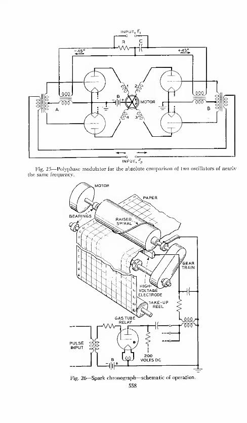
INPUT, f,
INPUT, f2
Fig. 25—Polyphase modulator for the absolute comparison of two oscillators of nearly
the same frequency.
Fig. 26—Spark chronograph—schematic of operation.
558

EVOLUTION OF QUARTZ CRYSTAL CLOCK ~>y)
way that there is a 90-degree phase shift between the two input voltages for
one of the frequencies, the lowest-frequency component appears asa sinusoidal
current in the output circuits 1, 2, 3 and 4 separated in phase by 90 electrical
degrees in cyclic rotation. The principal output, therefore, is a 4-phase
current having the frequency of the difference between the two inputs. If
the magnetic circuits are arranged geometrically as shown, the resulting
Fig. 27—Spark chronograph—close view of mechanism.
magnetic vector will rotate clockwise or counterclockwise depending on
which frequency is high, or will remain stationary, indicating the phase
relation, if the two frequencies are exactly equal.
Motors have been designed and are commercially available suitable for
operating synchronously from such polyphase modulators, and form an
excellent basis for the intercomparison of quartz oscillators and clocks with
ultra-high precision.
For making records of time comparisons the spark chronograph 84 shown
in Figs. 26 and 27 has served a very* useful purpose, combining in a single

560 BELL SYSTEM TECHNICAL JOURNAL
convenient instrument the means for comparing recurrent time phenomena
with an accuracy of a millisecond or two on a continuous chart which shows
the records for an entire week. Electrical impulses, related to the time
phenomena to be recorded, operate trigger tubes which discharge condensers
through the primary of an induction coil and cause sparks to jump from
a rotating spiral through a special chart paper having a dark colored backing
Fig. 28—Photomicrograph of single spark record showing nature of recording on wax-coated chart paper. X 100
and coated with a very thin layer of white wax. As the chart paper moves
slowly under the spiral, corresponding to the time abscissa, the succession
of sparks produces readily visible traces consisting of rows of tiny holes with
small areas around them where the wax is melted revealing the dark back-
ground. The holes are so small as to be scarcely visible, the darkened areas
constituting the visible trace. Figure 28 shows an enlargement of the
record of a single spark illustrating the nature of the marking. A recorder104
very much like the Bell Laboratories' spark chronograph is used currently
as part of the standard frequency and time broadcast equipment of the U. S.
Bureau of Standards.

evolution of quartz crystal clock 561
Applications of Quartz Clocks
The many useful properties of the quartz crystal clock have been the
reason for its wide and expanding application for the precise measurement
of time and rate.
First in historical order was the application to the measurement and con-
trol of frequency in communication. In this, the clock, through comparisons
with astronomical time, served as the means for determining the frequency
controlling it, the stability from the outset being great enough over intervals
of a day or more so that the average rate, as determined by daily checks with
time signals, was a very close approximation to the instantaneous rate at
any time intervening. The first of these clocks, already referred to 7", was
constructed in 1927 at the Bell Telephone Laboratories, in New York City,
primarily for use as an accurate standard of frequency. Since that first
experiment, three subsequent installations have been built in replacement
with progressively improved performance. The standard now in operation
(1947) was installed in 1937, using the first laboratory model GT crystals
and the first set of four bridge-stabilized oscillators, and has been in opera-
tion continuously since that time. Two of the four oscillators, mounted in a
temperature controlled booth, are shown in Fig. 29, and part of the auxiliary
equipment, including a clock dial, a spark chronograph and some monitoring
equipment, is shown in Fig. 30. This apparatus serves as the standard for
precise measurements of frequency and time throughout the Bell System and
is used to regulate the telephone Time of Day Service in New York City.
It is the standard of reference for the electric light and power services in
Metropolitan New York"15, and is used for a number of other similar services,
distributed through the medium of a submaster installation" 10 maintained
by the Long Lines Department of the American Telephone and Telegraph
Company. The original oscillators in this submaster installation were
controlled by electrostatically-coupled 4000-cycle steel tuning forks in vacuo
but recently have been replaced by improved oscillators controlled by 4000-
cycle bi-morph quartz resonators.
A clock shown in Fig. 31, which is on display in a window of the American
Telephone and Telegraph Company at 195 Broadway, is controlled from
this source. It is sometimes called "The World's Most Accurate Public
Clock".
The facility with which standard frequency and time services can be
provided and distributed is an outstanding feature of the quartz clock
development. Such services, having the accuracy of the primary controlling
standard, may be provided anywhere that can be reached through a suitable

562 BELL SYSTEM TECHNICAL JOURNAL
communication channel. As an example of this, a new primary standard
equipment is being constructed for installation at the Murray Hill, New
Jersey location of Bell Telephone Laboratories, the services of which will be
Fig. 29—Two of the four quartz oscillators of the Bell System Frequency Standard,
1937 to date.
made available through permananet wiring to all departments concerned.
A number of frequencies in the range from 60 to 10,000,000 cycles, all con-
trolled from the same crystal source, will be made available at some thirty
locations at the Murray Hill Laboratories, as well as to other laboratories

EVOLUTION OF QUARTZ CRYSTAL CLOCK 563
of the Bell System and, through the Long Lines Department, to outside
agencies.
A considerable number of quartz clocks have been built and used in
laboratories and observatories all over the world, some as standards of
Fig. 30—Clock dial and monitoring equipment associated with the Bell System Fre-quency Standard, 1937 to date.
frequency, some as precise clocks, and others for general use in all measure-
ments of rate and time. It would be impossible to mention all of these, for
already there are many of them. But certain installations are of especial
interest and will be discussed briefly.

564 BELL SYSTEM TECHNICAL JOURNAL
When the Crystal Clock was first described as such in April 1930, the idea
was discussed quite widely in Europe and America, and it was not long
before the work was duplicated and extended in other places. The first
outstanding application of the quartz clock to astronomy was made in
Fig 31—Display clock at 195 Broadway, New York. This clock, controlled by the
Bell System Frequency Standard, shows the same time as that of the New York Telephone
Time Service.
Germany with the installation at the Physikalisch-Technische Reichsanstalt
This was described by Scheibe and Adelsberger in 1932107 and 1934108, and
reports of its splendid performance continued periodically. It was with
this installation that it was possible for the first time to observe and measure
variations in the earth's rate occurring over intervals as short as a few weeks.
Previous measurements of such variations, involving studies of motion of the
moon, the planets, and Jupiter's satellites, had required years to obtain
EVOLUTIOX O/' QUARTZ CRYSTAL CLOCK 565
comparable information which, of course, by nature, could never reveal
short-term factors.
Soon after the inauguration of the quartz clocks at the Physikalisch-
Technische Reichsanstalt, somewhat similar installations were made at the
Prussian Geodetic Institute at Potsdam109, and at the Deutsche Seewarte in
Hamburg"". The latter has been moved because of war conditions and is nowthe Deutsche Hydrographische Institut. The quartz resonators used in these
installations are believed to be similar to those in Clocks III and IV in the
Physikalisch-Technische Reichsanstalt installation except that some of them
were made for 100 kilocycles instead of the original 60 kilocycles. They
were made by the firm Rohde and Schwarz where also is maintained a quartz
clock installation of extremely high precision 1U.
For a number of years the U. S. Bureau of Standards at Washington, D. ('.
has maintained a quartz clock installation for their extensive constant
frequency and time services. The early history of this installation was
described in some detail by E. L. Hall, V. E. Heaton and E. G. Clapham i.i
1935. 112 As is now well known, the Bureau broadcasts a number of precisely
controlled carrier frequencies at all limes, all of which carry standard time
and frequency modulations, including audible pitch standards and time
signals. The audible pitch standards are 4000 cycles and 440 cycles, while
the time signals consist of a succession of seconds pulses, continuous except
for certain omissions for the purpose of identifying longer time intervals.
All of these rates, including the carrier frequencies, are derived directly from
crystal oscillators and are known so well that their accuracy as transmitted
is estimated as one part in 50,000,000 at all times. The relative rates of the
standard oscillators are compared and recorded continuously at the Bureau
of Standards with an accuracy of one part in 10". The time signals involved
in these transmissions are so precise, and so convenient to use, that they
may be employed for the high-precision intercomparison of quartz clocks
across the Atlantic and for studies in astronomical time, heretofore difficult
or impossible to accomplish by any other means.
The present standard frequency and time service facilities at the U. S.
Bureau of Standards, which have been instituted under the general direction
of J. H. Dellinger, are described in recent separate articles1
'
l
by Vincent
E. Heaton and W. D. George respectively of the Bureau, both of whom have
made very substantial contributions to this development. The transmitting
station for the standard frequency broadcasts, which comprises a complete
set of quartz oscillators and control and measuring equipment, is shown in
Fig. 32.
The absolute rates for the crystal oscillators at the Bureau of Standards
are determined through cooperation with the U. S. Naval Observatory, also

566 BELL SYSTEM TECHNICAL JOURNAL
;
n
En

EVOLUTION OF QUARTZ CRYSTAL CLOCK 567
at Washington, where time determinations of great accuracy are made by
means of a Photographic Zenith Tube and a set of quartz clocks. A con-
tinuous precise check is maintained between these organizations by radio
communication so that the Naval Observatory time signals sent out from
NSS at Annapolis and other Navy stations, and from WWV the Bureau
of Standards radio transmitting station at Beltsville, Md., as well as all the
carrier frequencies from Beltsville, are very accurately determined and
maintained in agreement throughout.
The time studies of the U. S. Naval Observatory up to 1937 are described
in two important articles by J. F. Hellweg, then Superintendent of the
Observatory. The first of these" 3in 1932 describes the state of the art just
before the quartz clock entered the scene, and the second SHin 1937, already
referred to, tells of some of the first improvements brought about by its use
including the elegant method for making direct photographic time-star
checks of the crystal clock rate by means of the Photographic Zenith Tube.
Many of the advances involving the use of quartz clocks at the Naval
Observatory have not as yet been published.
The British Post Office and the National Physical Laboratory with labora-
tories at Dollis Hill and Teddington respectively, in cooperation with the
Royal Observatory at Greenwich, have done much the same sort of
thing in England in relation to time and frequency measurements and broad-
cast services as lias just been described. Considering the number of crystal
units among these organizations and the precise nature of the intercompari-
sons maintained between them, this is probably the most extensive and
elaborate quartz clock system in the world. In connection with Greenwich
Observatory alone, the complete installation includes eighteen or more such
clocks used in deriving the best possible mean rate from steller observations
at Greenwich and from studies of other time observatories throughout the
world.
An outline description of the quartz clocks of Greenwich Observatory, and
of their function there, has been discussed by Humphry M. Smith in Elec-
trical Times" 6 (London) in March 1946. These clocks employ for the most
part the GT cut crystal, lirst described by \Y. P. Mason, the bridge stabilized
oscillator circuit developed by L. A. Meacham, and the regenerative modula-
tor type of frequency dividers similar to those first developed by R. L.
Miller.
The accuracy of the quartz clocks exceeds that of the best pendulum
clocks with the result that quartz clocks are now used exclusively in the most
precise measurements of time. Some of the considerations" 7 leading up to
the adoption of quartz clocks at Greenwich were discussed in 1937 by H.
Spencer Jones, Astronomer Royal. Since then, reports have appeared from
time to time by the Astronomer Royal*9•" s and others" 9 concerning the

56S BELL SYSTEM TECHNICAL JOURNAL
adoption and use of quartz clocks there. Some interesting sidelights on this
"Precision Timekeeping Revolution" were written by F. Hope-Jones in two
articles 12" for the Horological Journal during the same year. The quartz
clock itself, as developed by the British Post Office for Greenwich Observa-
tory, was described 1 - 1in some detail by C. F. Booth in the P.O.E.E. Journal
for July 1946. A more general treatment involving some of the same
apparatus was presented 1 '2 by C. F. Booth and F. J. M. Laver in the I. E. E.
Journal of the same month.
Fig. 33—Crystal chronometer for geophysical studies, consisting of 100 KC. GT-cul
crystal, bridge oscillator, and frequency converters to derive precision 500-Cycle output
to operate timing devices.
An outstanding example of the versatility of the quartz clock has been its
application to the measurement of gravity at sea. Knowing of its stable
properties and its independence of gravity, Dr. Maurice Ewing in December
PASS, asked the Bell Telephone Laboratories whether a portable quartz
clock could be made available for use during a proposed gravity measuring
expedition by submarine in the West Indies. Since this was in line with
experimental work already in progress at the time, the first portable "crystal
chronometer", shown in Fig. 33, was assembled for this occasion, and was
taken by Ewing and his colleagues in the U. S. Submarine Barracuda on the
trip80 ' 81
which began at Coco Solo on November 30, 1936. This was the
first application of the GT crystal and the bridge stabilized oscillator in

EVOLUTION OF QUARTZ CRYSTAL CLOCK 569
portable equipment. This original crystal chronometer has been on several
gravity-measuring expeditions and is still in active service, having been used
again under Dr. Ewing's direction during the summer of 1947.
Gravity determinations at sea are made by measuring the rate of a special
triple pendulum that was invented by F. A. Vening Meinesz especially for use
in unsteady environments 123. Previously, the standard of rate had been
the usual ship's chronometers, but Ewing found the crystal chronometer to
be an improvement for his purposes, saying in part: ''This chronometer is not
thermostatted, and temperatures in a submarine change greatly during a
dive. Xo elaborate control over battery voltages was used. The cruise
started in the tropics and ended in Philadelphia in mid-winter. It is highly
significant that the interval between XAA-time and the chronometer-time
never exceeded 0.6 second during the six-week's cruise and that the
variation in this interval is very regular. The crystal chronometer has
reduced errors in gravity-measurements at sea, due to the rate of the chro-
nometer, to the point where they are negligible."
Some years previous to the construction of the crystal chronometer, a self-
contained quartz clock was made to illustrate the possibility of a compact
assembly, but it was not sufficiently portable for the submarine expedition.
This earlier clock was regulated by a quartz sphere such as used by 'crystal
gazers'. The frequency of the sphere was not adjusted, but its natural
frequency, which happened to be 3321 2, was adopted to operate a mean-time
dial by the choice of a suitable gear train. Since that time much more
compact assemblies have been built using more suitable crystals for control.
The stable properties of the quartz clock have been useful in a number of
cases requiring precise synchronization. Perhaps the most noteworthy
among these is the application to Long Range Navigation known as LORAN.Tn this application, pairs of transmitting stations, usually on shore and sep-
arated by accurately known distances, send out distinctive signals in syn-
chronism. The time interval between these signals, as received by a ship,
identifies the locus of all the points corresponding to that time interval.
The set of curves corresponding to all feasible time intervals defines one of
the coordinates in a two-coordinate system. The other coordinate is pro-
vided in identical manner by another pair of shore transmitters (which
may have one station in common with the first pair). The resulting coor-
dinate system consists of two families of intersecting hyperbolas. From the
geometry of these curves, and the constants of the signals, the complete
figure bounded by the ship and the transmitters can be determined readily.
The need for stability is evident from the fact that the relation between
time error and location error is roughly 5 microseconds per mile. In some
cases, location within a mile is highly desirable even at considerable dis-

570 BELL SYSTEM TECHNICAL JOURNAL
tances. Sometimes the two shore stations, operating as quartz clock time
transmitters, must operate for hours without intersynchronization, which
calls for very great constancy of rate. One microsecond per hour corre-
sponds to one part in 3.6 X 10 9.
The precise synchronization of mechanical parts in remotely situated
stations can be accomplished readily. For a number of years, the 5-band
privacy system of the transatlantic radio telephone sendee has been thus
synchronized, the apparatus at the American terminal being controlled by
the Bell System Frequency Standard while that at the English terminal
is controlled independently by similar equipment in the British Post
Office. The accuracy requirement for this particular purpose is not
very great. However, it has been found possible to maintain two or more
rotating shafts at remote and independent stations so precisely controlled by
independent quartz oscillators that they never depart, during hours of opera-
tion, by more than one fifth of one degree of arc.
A major project in which the quartz clock is destined to take an important
part is that of making world-wide land and water surveys in order to locate
more accurately boundaries and other features of the earth's surface. There
would be applications to sea and air navigation and it would be of great
value to geophysicists in studying the figure of, and changes in, the earth's
surface. By the combination of a widely dispersed set of Photographic
Zenith Tubes associated with quartz clocks and time signal means for com-
munication, and with the powerful ranging techniques growing out of
LORAN and RADAR, it should be possible to obtain a new order of ac-
curacy in long distance surveying.
The new order of accuracy of time measurement has made it possible for
the first time to study directly the variations in longitude caused by the
irregular wandering of the poles. These are small effects and heretofore
could only be determined by inference from observations of apparent
latitude variations at remote stations. With the added new techniques
it should be possible to learn a great deal about these and other phenomena
related to real or apparent variations in longitude.
Two other possible applications, involving the precise control of angular
movement so readily obtainable with synchronous motors operated from
quartz crystal controlled alternating current, are of considerable interest.
The first is that of operating the right ascension control of a telescope
directly from the amplified output of a crystal-controlled low frequency.
Vacuum tube amplifiers and synchronous motors are commercially available
with which this could be accomplished by suitable gearing. In addition, of
course, it would be necessary to include auxiliary controls to allow for
atmospheric and other transient effects, and for obtaining rates of motion

EVOLUTION OF QUARTZ CRYSTAL CLOCK 571
other than sidereal. For small and slowly changing effects this could be taken
care of very simply by means of electrical circuits now well known for addingor subtracting small changes in the control frequency.
The other application refers to a suggestion made by the author a fewyears ago 12
"" for the measurement of gravity, and changes in gravity, bycomparison of the forces Mg and M<a*R. The proposal was based on the
idea that « can be measured or produced with an accuracy two or moreorders greater than required, and that the problem reduces to that of balanc-
ing two forces and of measuring a linear displacement. The physical set-up
would be some form of conical pendulum driven at constant angular velocity
about the vertical axis under control of a crystal. Some such arrangements
are shown in the reference.
Future Possibilities
It is part of the nature of a scientist to extrapolate ahead of any current
development and to wonder what lies beyond. That feeling is certainly
justified in the field of time measurement, for the major advances havetaken place in so short a period and so recently, as compared with the
thousands of years during which Man has been time-conscious in somedegree, that it is reasonable to expect continued advancement for many years
to come. Such advancement may come as improvements and refinements
in existing techniques, or radically new methods may be developed withinherently more stable potentialities.
Accuracy of Rate
In the first place, it is not reasonable to suppose that the final accuracy
that can be attained with the quartz crystal clock has been reached; in viewof the rapid current progress indicated in the chart of Fig. 1, it is much too
soon to assume this, and there is considerable evidence that improvementscould be made by making fuller use of some of the stable properties of quartz
crystal and of refinements in the mounting and sustaining circuits. Thequartz oscillator assemblies in most general use at the present time embodysome compromises which it would not be necessary to make if an all-out
effort were being made to construct a few clocks having the highest attain-
able stability under the most favorable conditions of operation.
The first of these concerns the shape and size of the resonator itself and is
related to the frequency of oscillation. From the standpoint of stability of
operation, the actual frequency that is used in the oscillator is of little con-
cern because it is now a very simple matter to obtain low frequencies, suitable
for the operation of mechanisms, starting with any frequency that can becontrolled by a crystal resonator. The choice of 100,000 cycles for the first
zero-coefficient resonator was made because, as a standard of frequency,

572 BELL SYSTEM TECHNICAL JOURNAL
that value was a good median for the range of frequencies then used in
electrical communication. For use in a clock any other frequency would
answer just as well, so the inherent stability of the resonator should be given
first consideration.
One of the inhibitions imposed on the design of quartz resonators has
grown out of the dwindling available supply of large pieces of perfect crystal
quartz. Where large quantity production is involved this is an important
consideration, but for the small numbers required in a few observatories
and national laboratories it should not be a limiting factor.
Except for whatever added difficulties might be entailed in the mounting,
it seems reasonable that a large resonator should be more stable than a very
small one. The most fundamental reason for this is the proportionate
change in effective size that would result from the transfer of any surface
material including even the quartz itself.
Every substance is supposed to have some vapor pressure although in some
cases it is very minute. However, we are concerned with very minute
effects, and it is worthwhile to consider what would happen if there were any
evaporation or condensation of material. The possibility of this being an
important effect is evident when we realize that the removal of a single layer
of molecules from the end of a resonator one centimeter long would increase
its frequency by about five parts in a hundred million. The effect on
frequency would vary about inversely as the effective length, which favors
a large crystal. Such a transfer of material could be inhibited to some
extent by operating at a low temperature and by seeking equilibrium between
the quartz material of the resonator and other quartz material within the
same envelope. Of ourse, other materials than quartz may be involved in
similar surface phenomena and should be thoroughly studied and controlled.
This has a strong bearing, of course, on the use of conductive materials
deposited on a resonator for the purpose of electrical coupling to it.
The slightest trace of surface contamination has a deleterious effect on the
damping coefficient. Professor K. S. Van Dyke in 1935 made a series of
measurements on resonators of uniform shape and size but constructed with
a considerable range of surface treatments45. In the construction of different
resonators used in these tests he used diffeient grades of abrasive and
various amounts of etching with hydrofluoric acid. In these experiments he
operated them under varying degrees of refinement with regard to
contamination of the surfaces and found that the highest Q was obtain-
able only after the utmost care was exercised in keeping the surfaces
free from foreign material. The effect is so striking, in fact, that it leads
one to wonder whether there is any actual elastic hysteresis in the material
of quartz crystal, or whether the minute energy losses observed are entirely
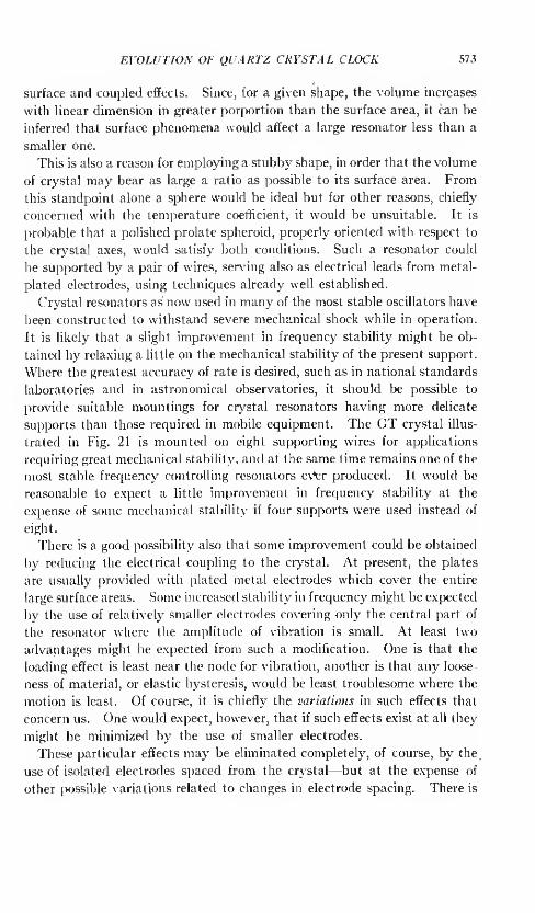
EVOLUTION OF QUARTZ CRYSTAL CLOCK 573
surface and coupled effects. Since, for a given shape, the volume increases
with linear dimension in greater porportion than the surface area, it can be
inferred that surface phenomena would affect a large resonator less than a
smaller one.
This is also a reason for employing a stubby shape, in order that the volume
of crystal may bear as large a ratio as possible to its surface area. From
this standpoint alone a sphere would be ideal but for other reasons, chiefly
concerned with the temperature coefficient, it would be unsuitable. It is
probable that a polished prolate spheroid, properly oriented with respect to
the crystal axes, would satisfy both conditions. Such a resonator could
be supported by a pair of wires, serving also as electrical leads from metal-
plated electrodes, using techniques already well established.
Crystal resonators as now used in many of the most stable oscillators have
been constructed to withstand severe mechanical shock while in operation.
It is likely that a slight improvement in frequency stability might be ob-
tained by relaxing a little on the mechanical stability of the present support.
Where the greatest accuracy of rate is desired, such as in national standards
laboratories and in astronomical observatories, it should be possible to
provide suitable mountings for crystal resonators having more delicate
supports than those required in mobile equipment. The GT crystal illus-
trated in Fig. 21 is mounted on eight supporting wires for applications
requiring great mechanical stability, and at the same time remains one of the
most stable frequency controlling resonators e\*er produced. It would be
reasonable to expect a little improvement in frequency stability at the
expense of some mechanical stability if four supports were used instead of
eight.
There is a good possibility also that some improvement could be obtained
by reducing the electrical coupling to the crystal. At present, the plates
are usually provided with plated metal electrodes which cover the entire
large surface areas. Some increased stability in frequency might be expected
by the use of relatively smaller electrodes covering only the central part of
the resonator where the amplitude of vibration is small. At least two
advantages might be expected from such a modification. One is that the
loading effect is least near the node for vibration, another is that any loose-
ness of material, or elastic hysteresis, would be least troublesome where the
motion is least. Of course, it is chiefly the variations in such effects that
concern us. One would expect, however, that if such effects exist at all they
might be minimized by the use of smaller electrodes.
These particular effects may be eliminated completely, of course, by the
use of isolated electrodes spaced from the crystal—but at the expense of
other possible variations related to changes in electrode spacing. There is

574 BELL SYSTEM TECHNICAL JOURNAL
considerable promise in such means, the end result depending upon how
precisely the resonator may be held in a fixed position by means that will
not change its resonance characteristics. Such means have, in fact, been
used successfully in a number of German quartz clocks such as at the
Physikalisch-Technische Reichsanstalt 1 "8, and with the Dye ring resonator
developed by D. W. Dye and L. Essen at the National Physical Labora-
tory 125-126
, England.
For any given resonator and circuit a careful study would probably reveal
an optimum amplitude of oscillation that would yield a maximum stability
against residual uncontrollable variables. With the GT crystal, as used
currently, the maximum amplitude of motion is about 0.00006 mm. It
would be possible to limit the motion to a tenth or a hundredth of this value
if it should be found desirable.
Further studies of the factors contributing to aging of the quartz material
also should produce valuable improvements. Since resonators, which ap-
pear to be alike in all other respects, often age at greatly different rates, some
being very small or substantially zero, it would seem that some reason should
be discoverable for such variations and some effective control established.
There are other relatively massive shapes that should be investigated
further such as the ring crystal, mentioned earlier in this paper, and as
developed and studied by Dye and Essen 1 '-5•
m. The ring may be excited
in various modes of vibration some of which are more favorable than others
from the standpoint of mounting. By choice of orientation relative to the
crystal axes, and of dimensions, certain of these can be designed to have zero
temperature coefficients in a restricted temperature region.
Another shape that holds great promise because of its convenience of
mounting, along with the other desirable properties, is the rectangular rod
vibrating longitudinally in its second or higher overtone such as first de-
scribed by Scheibe and Adelsberger108. Still another possible massive
shape is a much thicker version of the GT crystal which would combine the
very favorable temperature-frequency characteristic with that of reducing
the ratio of surface area to volume.
In seeking the highest possible accuracy a precise temperature control is
essential in all cases, even with the GT type of resonator with its wide region
of low-temperature coefficient. The reason for this is that the frequency of
oscillation depends not only on the mean temperature of the resonator but
also upon the temperature gradient throughout its volume. Thus, even if a
resonator has the same frequency exactly at different mean temperatures,
its frequency will vary a little while the temperature is varying from one
value to another. The effect of this can be reduced by enclosing the crystal
unit in an envelope with thermal lagging so that such variations as do exist
at the temperature control layer are prevented from reaching the crystal.
EVOLUTION OF QUARTZ CRYSTAL CLOCK 575
This is no longer a serious problem for there are various electronic means
such as described by C. F. Booth and E. J. C. Dixon127 for continuous tem-
perature control, by means of which the variations may be kept very small,
and very effective thermal lagging methods128 are well known.
The bridge method for temperature control has been applied in manyforms. One of the simplest and most effective procedures has been to
utilize a bridge-stabilized oscillator of the type developed by L. A. Meachamfor frequency control, and to use it instead for temperature control. For this
purpose, all four arms of the bridge are noninductive resistances wound as
heaters on the oven to be controlled. In the feedback circuit of the oscillator,
a rough frequency control is included simply for the purpose of setting up an
oscillation in the circuit which includes the bridge. The conjugate pairs of
bridge arms are made of resistance wire with different temperature coefficients
and so proportioned that the bridge balances at the desired temperature.
The amplitude at which this bridge oscillator oscillates depends upon the
temperature departure from the balance value. Since the alternating cur-
rent output of the oscillator flows in the bridge arms, the amount of heating
is proportional to the temperature error, and hence the control is automatic.
Continuity of Operation
An astronomical clock, in addition to having as nearly constant a rate as
can be attained, should also be able to operate over long periods of time with-
out change or interruption. The reason for this is that many of the phe-
nomena that are of interest in time measurement occur in continuous succes-
sion and the greatest amount of information can be obtained only by the use
of clocks with which measurements can be made in unbroken sequence.
Quartz clocks that have been used for astronomical purposes to date have
not had a very commendable record in this respect and already a good deal
has been said in the clock literature about this aspect—as though it were an
inherent property of the quartz clock.
However, it is only a matter of simple engineering, making use of tech-
niques and apparatus already well known and available, to design a quartz
clock which should operate continuously for many years. A chain is only
as strong as its weakest link—and the clock comprises a chain of apparatus
parts every link of which must function perfectly and continuously. This
chain consists of (1) the crystal-controlled oscillator, (2) a frequency de-
multiplier to obtain a low frequency to operate a motor, (3) a power amplifier
to obtain sufficient current to drive the motor and (4) the motor itself, associ-
ated with any of a wide assortment of time signal-producing or measuring
equipment. In addition to the links in this chain, a power supply must be
maintained, and the temperature of the crystal must be controlled, both
continuouslv.

576 BELL SYSTEM TECHNICAL JOURNAL
The crystal itself is no problem as far as continuity of operation is con-
cerned. Its motion is so very small there is no likelihood at all of failure on
that account. Mountings are very stable and in all likelihood will be
improved. The oscillator circuit, the frequency demultiplier, the power
amplifier and the temperature-control circuit are all vacuum-tube devices
and deserve special consideration. In all of these circuits, vacuum tubes
have been used in some installations which do not have a very long life,
some even becoming defective within a year of operation. On the other
hand, there are tubes which have been developed for use in continuous
telephone circuits where failures would be troublesome and costly. Some of
these tubes in current production have an expected life of more than ten
years. There is good reason to believe that a quartz clock installation
equipped with such vacuum tubes throughout, and engineered so as to make
effective use of their special properties, would operate continuously for ten
years or more.
The remaining "link" in the chain is the synchronous mechanism operated
from the crystal-controlled circuits and used for totalizing continuously the
oscillations of the crystal and for producing suitable time signals at specified
intervals of time thus measured off in terms of the crystal rate. This
mechanism usually consists of a small synchronous (phonic wheel) motor
operated from a submultiple of the crystal frequency and geared to com-
mutators or cams or other means for producing the electrical signals used
in making time measurements. Many of the troubles in quartz clock in-
stallations have occurred in this 'link'. There is every reason to believe,
however, that suitable synchronous motors geared to cam-controlled elec-
trical contacts can be built that will operate continuously through many
years. To insure long operation it would be desirable to employ motors
with low rotation speed in order to reduce bearing wear. With the present
knowledge of bearing materials and lubricants, it should be a simple matter
to design such a motor that would operate without failure for ten years or
more.
A relatively trouble-free electrical time signal producer, suitable for
operating under the control of a quartz oscillator, with frequency demulti-
pliers to 100 cycles, could be constructed as indicated schematically in Fig.
34. This is not intended to be an actual design, but is intended to indicate
how an apparatus could be designed that would circumvent some of the
troubles now experienced which prevent long continuous operation.
The basic apparatus consists of a crystal oscillator, presumably 100,000
cycles, with a frequency divider to obtain controlled 100-cycle current to
drive the 100-pole phonic wheel motor at one revolution per second. Ob-
viously, other crystal frequencies and step-down ratios could be used, the

EVOLUTION OF QUARTZ CRYSTAL CLOCK 577
important thing being to obtain a rotation speed of 1 rps. This is a very
low speed for a phonic wheel motor but has the obvious advantage of great
simplicity since it permits of controlling seconds devices without the use of
gearing. Only one shaft is involved and the bearing problem is reduced
to the simplest possible terms. A hardened steel cam, integrally mounted
with the phonic wheel rotor, is used to operate a single electrical contact, so
connected into the circuits controlled by it that the instant of break is the sole
time-determining operation. A break signal is preferable to a make signal
chiefly because it is easier to avoid irregular effects, such as result from
contact chatter, when a circuit is being opened than when it is being closed.
If a pallet of sapphire or ruby is used for the mechanical contact on the cam}
DRIVESTATOR
FREQUENCYDIVIDER U i-l
100-KCCRYSTAL
V
AMPLIFIER sSAPPHIRE OR RUBY
jddvlW&W/l/l^'' PALLET
TOMEASURINGCIRCUITS
HARD-STEELCAM
PHONIC WHEELAFEEb.BACK 1„ (100 POLES)
0) +
UJ
SoPICK-UPSTATOR
INSTANTOF BREAK
kFig. 34—Suggestion of elements for a quartz clock for long time continuous operation.
and if small currents are used through the contacts, made preferably of
platinum-iridium or similar alloy, it would be reasonable to expect trouble-
free performance through several hundred million operations.
Ordinarily, the "hunting" of a phonic wheel motor operating on a fre-
quency as low as 100 cycles would cause time errors too large to neglect in a
device such as just described. However, by the use of feedback in the
motor amplifier circuit, such as indicated schematically in Fig. 34, the
effective hunting can be reduced to the point where the time errors caused
by it would become negligible for most purposes.
Various circuits could be suggested for making use of the break signal for
timing purposes, the one shown in Fig. 34 being typical and suitable for
various methods of precise measurement and control. It is capable of
providing an electrical impulse with a steep wave front and of adjustable
duration. The grid of the vacuum tube is normally biased to cutoff by the

578 BELL SYSTEM TECHNICAL JOURNAL
negative voltage, n \ t, . While the contact is closed, the battery £2> with
resistance R3 in series, is short-circuited. But at the instant of opening the
contact, current flows momentarily in the circuit including E2 , R3, C and R2 .
By making £2 positive, and equal to or larger than E\ numerically, the plate
circuit of the tube becomes conducting for a short interval, the duration of
which is determined by the time-constant of the condenser circuit, each time
the contact is opened. At all other times, the plate circuit is nonconducting.
The sharply defined electrical signal thus produced in the plate circuit can
be used by well-known means for direct time comparison with signals from
other sources.
Making use of the duration of the impulse thus produced, it is possible to
use it as a selecting means to isolate a single more precise signal from a
continuous chain. For example, the 100-cycle wave controlled by the
crystal can be modified by a simple vacuum tube circuit to consist of a con-
tinuous sequence of very sharply defined impulses. By using the pulse
circuit just described as a bias control on an amplifier, it would be readily
possible to select one out of every hundred of these impulses and thus provide
an extremely precise seconds signal, the accuracy of which is determined
wholly by electronic means.
It would be readily possible to vary the time relation of the seconds signal
while in operation, by the use of electrical phase shifters in the driving
circuits, or by rotating the stator of the phonic wheel motor, but for long
continuous operation it would be desirable to keep the number of apparatus
parts comprising the clock at a minimum.
It is not necessary, of course, to employ a complete frequency divider and
phonic wheel apparatus for each quartz crystal oscillator. As mentioned
previously, the relative time rates of quartz oscillators can be measured with
very high precision and be very simple means through a direct comparison of
the high frequencies.
Other Meansfor Precise Rate Control
In addition to making improvements on the quartz crystal resonator, and
on methods for sustaining it in vibration, there are two other avenues of in-
vestigation which may yield comparable resulfs, with possibly some addi-
tional advantages. Not much can be said about them at this time except to
point out their possibilities because no appreciable work has been done so
far to explore their merits as timekeepers.
The first is in the field of very low temperatures where some quite re-
markable properties are obtained. Chief of these for our purpose is the
supraconductivity of some metals, and the constancy of shape of most
materials, at temperatures in the neighborhood of absolute zero. It seems

EVOLUTION OF QUARTZ CRYSTAL CLOCK 579
reasonable to suppose that an electrically-resonant circuit maintained at atemperature in this region could be made to have a very high Q, and verystable dimensions, and so have the chief desirable properties for rate control
that obtain in a quartz resonator. Resonant cavities used at high fre-
quencies have many of the properties of other electrical resonant circuits,
and in particular their energy dissipation for electric oscillations can be very'
substantially reduced when cooled to superconducting temperatures. Insome experiments made recently at Massachusetts Institute of Technology 1
-' 9
it has been shown that a cavity resonator made of lead, which for 3-cm.waves has a Q of about 2,(KK) at room temperatures, is so much improved at a
temperature of 4 degrees absolute that the Q approaches a million. Such aresonator could be used as the stabilizing element in an oscillator and hencein a clock. The relative stability over long periods could, of course, bedetermined only by experiment.
Maintenance of the required low temperature would add considerably tothe complexity of such a system, but if the advantages were such as to pro-duce a new order of stability, and particularly if it should make possible a
clock system with small or zero aging, it certainly should be justified for
future time measurement studies.
The other avenue of approach is through the application of certain
resonance phenomena in atoms and molecules that do not depend uponaggregates of matter as is the case with all mechanical systems used hereto-
fore in time measuring means. The extreme fineness of structure and theconstancy of atomic and molecular resonance phenomena have long beenrecognized through studies of line spectra, and in the field of spectroscopythese properties have been used as standards of wavelength ever since theearly studies of Joseph von Fraunhofer, reported in 1815. ,3n Wavelength, X,
and frequency,/, are associated by the simple relation/ = - where c is equal
to the velocity of light. For visible radiations/ turns out to be extremelylarge, for the red light, 6500A, it is 462 million million vibrations per second.So far, such high frequencies have not been observable or measurable di-
rectly but can only be deduced from wavelength measurements as juststated—which inevitably invoke the use of man-made standards of
length and the combined errors of two quite different sorts of physicalmeasurements.
It has long been the dream of physicists to find some way to tie in directly
with the natural frequencies of atoms and molecules and to derive from thema direct measure of rate, and, of course, of time interval. It has beenthought, for example, that the red radiation from cadmium vapor, whosewavelength was measured by C. Fabry and A. Perot in terms of the standardmeter as accurately as that standard could be. defined, would also make a

580 BELL SYSTEM TECHNICAL JOURNAL
good standard for time measurements. A step in the right direction was
made later by A. A. Michelson whose precise determination of the wave-
length of this radiation made possible the redefinition of the International
Meter as a definite number of such wavelengths, measured in vacuo. From
this definition, it is now possible to duplicate the primary standard of
length with great accuracy, and to check such secular changes as may occur
in the original standard,. the distance between two marks on a metal bar.
The constancy of the standard, as defined by Michelson, depends upon
properties of primary particles of matter, and upon properties of space,
which, as far as human beings are concerned directly, appear to be quite
independent of time or location. A similar definition of rate, or time inter-
val, is very desirable.
A ray of hope came out of the important work of Nichols and Tear131 who
proved that electric waves which could be produced electrically were of the
same stuff as radiation from hot bodies. They were able to detect radiation
of either sort by the same receiving device and showed that they both had
the same properties of refraction, polarization, etc. Later, Cleeton and
Williams132 were able to produce continuous electric waves at very high
frequencies—corresponding to about 1 cm. wavelength—and to show that
they also had the important properties of light waves. Now the range has
been extended somewhat more and there are reports138 of experimental
generators that can produce continuous waves of a few millimeters wave-
length. This is an active development and, of course, the end is not in
sight. From continuous waves of any frequency it is believed possible by
general techniques now well known to control lower frequencies, and from
them eventually all sorts of time measuring and indicating devices as pre-
viously described.
Within the last few years, the missing link has been discovered which, with
Suitable instrumentation, may make it possible to construct a clock con-
trolled by atomic- or molecular-resonance phenomena. There are a great
number of resonance phenomena associated with the molecules in a gas, or in
molecular beams, which are responsive to electric waves that can be pro-
duced continuously by modern vacuum tube means. In some cases, the
sharpness of resonance is such that changes of frequency of one part in 108 or
less can be detected, leading to the idea that such resonance phenomena may
be utilized in some way to control the frequency of a suitable oscillator and
hence, through frequency conversion circuits, to control frequencies low
enough to operate clocks and other mechanisms. Some of the resonance
phenomena in point are in the one-centimeter region, a field that is rapidly
being exploited in radar and communication applications. It is to be
expected, therefore, that techniques for dealing with such high frequencies
will be developed in the near future thus facilitating a study of this new

EVOLUTION OF QUARTZ CRYSTAL CLOCK 581
approach to timekeeping. The idea of utilizing such resonance phenomena
for the measurement of time was suggested in January, 1945 by Professor
1. 1. Rabi of Columbia University at an address before the American Physical
Society and the American Association of Physics Teachers.
These resonance phenomena, involving the interaction of microwave
electromagnetic radiation with atoms or molecules of matter, have been dis-
covered only quite recently and it is likely that a great deal more will be
learned about them in the next few years. The results already obtained are
very promising and investigations already under way may well lead to the
means for creating an entirely new type of standard of time interval and
rate—both of prime importance in Physics.
The studies of greatest significance for such purposes now in progress fall
in two main branches involving quite different techniques. The actual
means for regulating a clock would be quite different in the two methods,
but would be possible in either. With what is known up to the present time,
however, the construction of such a clock would be a considerable under-
taking, especially to make one that would operate over long periods. The
two chief phenomena involving atomic or molecular resonances are: (1) the
absorption of high-frequency energy in certain materials, particularly in
gases, exhibiting ultra-line absorption spectra; and (2) the deflection of
beams of atoms or molecules under special conditions of magnetic and
electric fields. The earliest reported work on the absorption of microwaves
in gases was done by C. E. Cleeton and N. H. Williams134 in 1934. With
the development of improved high-frequency generators and measuring
techniques the work has been extended considerably during the last few
years by C. If. Townes135, W. E. (Jood136 and others. It is believed that
with modifications of methods, such as used by them, it would be possible to
control the frequency of the short-wave generators such as used in making
these studies; and, if this can be done, the adaptation for use in time-measur-
ing devices would follow naturally as in the case of any other stable
oscillator.
The general method using molecular beams has been a gradual develop-
ment over some years, but the first published suggestion of the applications
which relates closely to this work was made in 1938 when I. I. Rabi, J. R.
Zacharias, S. Millman and P. Kusch first used the beam deflection method for
measuring nuclear magnetic moments. 137 Two articles 13"' 139 in Reviews of
Modem Physics in July 1946 give a good description of the molecular beam
method and the results of some studies of fine structure resonance phe-
nomena. The resonance curve shown in Fig. 35 obtained recently by P.
Kusch and H. Taub of Columbia University, and hitherto unpublished,
illustrates the resolution obtainable by molecular beam methods. According
to theory, the actual width of the resonance should be substantially inde-

582 BELL SYSTEM TECHNICAL JOURNAL
pendent of the applied frequency and they expect to be able, when employing
frequencies corresponding to centimeter waves, to obtain a hundred or more
times this resolution. If this should be realized, it suggests the possibility of
a clock with an accuracy of better than one part in 108.
Perhaps the greatest advantage that might be expected from such a
method lies in the possible long-time stability or freedom from aging.
Every existing means for timekeeping involves in some manner the motion of
large aggregates of matter which, when they rearrange themselves in anyway,
vary their rates of rotation, or of oscillation, as the case may be, in ways
8 10 12 14 16 18 20Af IN KILOCYCLES PER SECOND
Fig. 35—Typical resonance curve for a line in the radio frequency spectrum of atomic
K 39 observed by the method of molecular beams. Experimental data supplied by P.
Kusch and H. Taub, Columbia University Physics Department.
that are not wholly predictable. It may well develop that a method based
on the behavior of single particles of matter will be ageless and, with proper
instrumentation, that it will permit of setting up an absolute standard of rate
and time interval. The actual value of this rate would be indeterminate by
a small amount depending on the sharpness of resonance and the precision of
control that could be effected from it, in addition to any uncontrollable
effects of the actual resonance frequencies such as result from temperature,
pressure, and electromagnetic and gravitational force fields. In the case of
some of the resonance phenomena all the latter effects are believed to be

EVOLUTION OF QUARTZ CRYSTAL CLOCK 583
vanishingly small. In any case, one would not expect to experience a pro-
gressive change in rate as in the case of the rotation of the earth which now
is the measure and definition of astronomical time. On the average the
earth is said to be slowing down at the rate of a thousandth of a second per
day per century1*1 and, according to the astronomers*9, the day will continue
to lengthen until finally, at some time in the distant future, the earth will
always face one side toward the moon and the length of the day will become
about 47 times as long as it is at the present time.
Meanwhile, if an absolute standard could be established, such as now
appears feasible through atomic- or molecular-resonance phenomena, it
would be possible to record these changes through the centuries and to
establish a relatively stable "second" that could be used for all time in
physical measurements in place of the elastic second of the cgs system which,
as now defined, must stretch with the inevitable variations in the meansolar day.
Whether or not such an '"absolute" clock becomes a reality at some time
in the future, the quartz crystal clock, because of its accuracy, compactness,
great convenience and versatility is likely to continue to be a most useful
instrument in all precision measurements of time.
References
1. The beginnings of Time-Measurement and the Origins of Our Calendar. JamesArthur Foundation Lecture), James Henry Breasted. Published in Hook, TimeAnd Its Mysteries, 1936. New York University Press.
2. Encyclopedia Brilannica— 14th Ed.—"Christian Huygens".
3. Horologium Oscillatorium, Christian Huygens, 1673.
4. Electrical Timekeeping, F. Hope-Jones, N. A. G. Press, London, 1940.
5. Improvements in the Application of Moving Power to Clocks and Timepieces, JohnBarwise and Alexander Bain, British Patent No. 8783, Filed Jan. 11, 1841, Issued
July 10, 1841.
6. The firs! electric clock, W. A. Marrison. Proceedings of the Engineering Society,
Queens University, Kingston, Canada, v. 29, pp. 15-20, 1940.
7. Electric Clocks, F. Hope-Jones - Book, N. A. G. Press, London, 1931.
8. Memoire sur l'6tude optique des mouvements vihratoires, Jules Lissajous, Coinples
Reudus, v. 44, p. 727, April 6, 1857.
9. On the use of the dynamic multiplier with a new accompanying apparatus, C. G.Page, American Journal of Science. 1st Series, 32. 1837, p. 354, dated at Salem,Mass. April 24, 1837.
10. Observations on induced electric currents with a description of a magnetic contact
breaker, Golding Bird, London, Edinburgh and Dublin. Phil. Mag. Series 3, No.12, 1838, p. 18. Addressed from Wilmington Square, Nov. 2, 1837.
1 1
.
On a new magnetic electric machine. Annals of Electricity, Magnetism and Chemistryand Guardian of Experimental Science, vol. Ill, pp. 66-70, 1839. Translation
from German. Describes apparatus of Dr. Neeff of Frankfurt exhibited at
Friburg meeting of Philosophers, September, 1838.
12. Science of Musical Sounds, Davton Clarence Miller. Book, Macmillan, N. V.
1916. p. 29.
13. Quelques Experiences d' Acoustique, Rudolph Konig, Paris, 1882. p. 172.
14. On the characteristics of electricallv operated tuning forks, H. M. Dadourian,Physical Rrciev, v. 13, pp. 337-359, May, 1919.
15. Isochronous and Svnchronous Movements for Telegraph and Other Lines. PatentNo. 203423, Poul la Cour. Filed April 9, 1878.

584 BELL SYSTEM TECHNICAL JOURNAL
15a. Roue phonique pour la regularisation du synchronismc des mouvemcnts. Note by
P. la Cour in Comptes Rendus, v. 87, pp. 499-500, September 25, 1878.
16. Report of Physical Society Meeting of March 30, 1878. Refers to Lord Rayleigh's
impulse motor. Nature, May 23, 1878, p. 111.
17. Nouvcaux modes d'entretien des diapasons, A. and V. Guillet. Com pics Rendus,
v. 130, pp. 1002-1004, April 9, 1900.
18. The Emission of Electricity from Hot Bodies, O. \V. Richardson. Book. Longman,
Green and Co., London, 1916.
19. On electric discharge between electrodes at different temperature in air and high
vacuo, J. A. Fleming, Royal Society of London Proc, v. 47, p. 122, 1890.
20. The Audion—A New Receiver for Wireless Telegraphy, Lee De Forest, A. I.E. E.
Transactions, v. 25, pp. 735-779, 1906. Electrician, v. 58. pp. 216-218, 1906.
21. Improvements in instruments for detecting and measuring alternating currents,
J. A. Fleming. British Patent No. 24850, 1904.
22. Device for amplifying feeble electrical currents, Lee De Forest. U. S. Patent No.
841387, issued January, 1907.
2^i. Einrichtung zur Erzeugung elektrischer Schwingungen, Siegmund Strauss. . I ustrian
Patent No. 71340, filed Dec. 1912, issued June, 1915.
24. Improvements in receivers for use in wireless telegraphy and telephony, Marconi
Wireless Telegraph Company, Ltd. and Charles Samuel Franklin. British Patent
No. 13636, filed June, 1913, accepted June, 1914.
25. Wireless Telegraph and Telephone System, Lee De Forest. U. S. Patent No.
1.507.016, filed September, 1915, issued September, 1924, and U. S. Patent No.
1.507.017, filed March, 1914, issued September, 1924.
26. The use of the triode valve in maintaining the vibration of a tuning fork. W. H.
Eccles, Phys. Soc. of London Proc, v. 31, p. 269, 1919.
27. Sustaining the vibration of a tuning fork by a triode valve, W. H. Eccles and F. W.Jordan, The Electrician, v. 82, p. 704, June 20, 1919.
28. Sur L'entretien des oscillations mechaniques au moyen des lampes a trois electrodes,
Henri Abraham and Eugene Block, Comptes Rendus, v. 168, pp. 1197-1198, June
16, 1919.
20 Electron tube drive for tuning fork, E. A. Eckhardt, J. C. Karchcr, and M. Keiser,
Physical Review, v. 17, pp. 535-536, April, 1921.
30. An electron tube tuning fork drive, E. A. Eckhardt, J. C. Karcher and M. Keiser,
J.O.S.A.-'So. 6, pp. 949-957, November, 1922.
31. The valve maintained tuning fork as a precision time standard, D. W. Dye, Royal
Soc. of London Proc, v. 103, pp. 240-260, May, 1923.
32. Frequency measurements in electrical communication, J. W. Norton, N. H. Kicker,
W. A. Marrison, A. I. E. E. Trans., v. 42, pp. 730-741, June, 1923.
M. A celestial encounter, Ernest William Brown, Jl. Franklin Institute, v. 202, pp. 127-
163, August, 1926.
34. The best observed eclipse in history, Scientific American, March, 1925, p. 155.
35. Precision determination of frequency, J. W. Horton and W. A. Marrison. /. A'. E.
Proc, v. 16, pp. 137-154, February, 1928.
36. The valve maintained tuning fork as a primary standard of frequency, I). W. Dye
and L. Essen, Royal Society of London Proc, v. 143, pp. 285-306, 1934.
37 The anomaly of nickel steels, Charles Edouard Guillaume, Physical Soc. of London
Proc, v. 32. p. 374, April. 1928.
38. La compensation des horloges et des montres; precedes nouveaux fondes sur l'emploi
des aciers au nickel, Charles Edouard Guillaume. Booklet—Neuchatel et Geneve,
Paris, 1920.
39. Dilatibilite du chrome et des alliages nickel-chrome dans un intervalle etendu de
temperature, P. Chevenard. Comptes Rendus, v. 174, p. 109, January, 1922.
40. Mesure de la dilation du coefficient thermoelastique et proprietes 61ectriques des
alliages dans un grand intervalle de temperature. R6sultats de l'gtude des ferro-
nickels purs et additonnes le chrome. P. Ch6venard. Bull. Soc. Franc. Phy.
No. 254, pp. 135-138, Dec. 16, 1927.
41. Tuning forks, H. H. Hagland. U. S. Patent 1,715,324, filed June, 1925, issued May,1929.
42. A mechanical oscillator of constant frequency, August Karolous. U. S. Patent
1,763,853, filed Nov., 1927, issued June, 1930.
43. Compensated Tuning Fork, Bert Eisenhour. U. S. Patent 1,880,923, filed Sept.,
1930, issued Oct., 1932.
EVOLUTION OF QUARTZ CRYSTAL CLOCK 58S
44. Tuning Fork, S. E. Michaels. U. S. Patent 2,247,960, issued July 1, 1941.
45 A determination of some of the properties of the piezoelectric quartz resonator,
Karl S. Van Dyke, Proc. I. R. E., v. 23, No. 4, April, 1935.
46 The high O of quartz resonators, Mavnard Waltz and K. S. Van Dvke, Jl. of Acous-
tical Soc". of America, v. 19, No. 4, Part 1, p. 732, July, 1947.
47 The crystal clock, W. A. Marrison, National Academy of Sciences Proc, v. 16, pp.
496-507, July, 1930.
48. Development par pression, de l'electricite polaire dans les cristaux hemiedres a faces
inclinees, Jacques and Pierre Curie, Coinpies Rendits, v. 91, p. 294, 1880.
49. Deformations elcctrique du quarts, Jacques and Pierre Curie, Comptes Rendits, v.
95, pp. 914-197, 1882.
50. Oeuvres de Pierre Curie, Pierre Curie. Book—Gaulhier-Villars, Paris, 1908.
51. The electric network equivalent of a piezoelectric resonator, K. S. Van Dyke, Phys.
Rev., v. 25, p. 895, 1925.
52 The piezoelectric effect in the composite rochelle salt crystal, A. McLean Nicolson,
A. I.E. E. Trans., v. 38, Part 2, pp. 1467-1485, 1919. A. I. E. E. Proc, v. 38,
pp. 1315-1333, 1919.
53 Generating and transmitting electric currents, Alexander M. Nicolson. U. S.
Patent No. 2,212,845, filed April 10, 1918, issued August 27, 1940.
54. Sondage par le son, P. Langevin. 5. 29, Pub. Spec. No. 3, 1924.
55. Improvements relating to the emission and reception of submarine waves, P. Langevin.
French Patent No. 505,903 issued in 1918, also British Patent No. 145,691 issued
in 1921.
56. The piezoelectric resonator, W. G. Cady. /. R. E. Proc, v. 10, pp. 83-114, April,
1922.
57 Piezoelektrische Resonanzerscheinungen, A. Scheibe, Zeitschrift fur Hochfrequenz-
lechnik, v. 28, No. 1, 1926.
58 Bibliography on piezoelectricity, W. G. Cady, /. R. E. Proc, v. 16, pp. 521-535,
1928.
59. Quarzoszillatoren, R. Bechmann. Telefunken Zeilnng, v. 17, pp. 36-45, March,
1936.
60. Piezoelectricity, W. G. Cady. Book—McGraw-Hill, New York, 1946.
61. Piezoelectric crystal resonators and crystal oscillators applied to the precision
calibration of wave meters, George W. Pierce, Amer. Acad, of Arts and Sciences
Proc, v. 59, No. 4, pp. 81-106, October, 1923.
62 Sur un nouvel emploi des quartz piczoelectriques, G. Siadbei, Comptes Rendits, v.
188, p. 1390, May, 1929.
63. Piezoelectric crystal oscillators applied to the precision measurement of the velocity
of sound in air and carbon dioxide at high frequencies, George W. Pierce, Amer.
Acad, of Arts and Sciences Proc, v. 60, pp. 271-302, October, 1925.
64. Sichtbarmachung von hochfrequenten longiludinalschwingungen piezoelektrischen
Kristallstabe, E. Giebe and A. Scheibe, Zietsf. pliysik v. 33, pp. 335-344, 1925.
65 Leuchtende piezoelektrische resonatoren als hochfrequenznormale, E. Giebe and A.
Scheibe, E. T. Z., v. 47, pp. 380-385, April, 1926.
66 An international comparison of frequency bv means of a luminous quartz resonator,
S. Jimbo, Proc. J. R. E., v. 18, pp. 1930-1934, 1930.
67 An international comparison of radio wavelength standards by means of pie oelectric
resonators, W. G. Cady, Proc I. R. E., v. 12, pp. 805-816, December, 1924.
68 The status of frequency standardization, J. H. Dellinger. Proc. I. R. E., v. 16, No.
5, pp. 579-592, May, 1928.
69. Frequency control system, Warren A. Marrison. U. S. Patent No. 1,788,533, filed
March,' 1927, issued January, 1931.
70. Precision determination of frequency, J. W. Horton and W. A. Marrison. /. R. E.
Proc, v. 16, pp. 137-154, February, 1928.
71. Sur la mesure en valcur absolue des periodes des oscillations electriques de haute
frequence, Henri Abraham et Eugene Block, Comptes Rendits, v. 168, pp. 1105-
1108, 1919.
72. "Universal" frequency standardization from a single frequency standard, J. K.
Clapp, /. O. S. A., v". 15, No. 1, pp. 25-47, July, 1927.
73 Frequency demultiplication, Balth Van der Pol and J. Van der Mark, Nature, v.
120, pp. 363-364, Sept., 1927.
74 Uber Relaxationschwingungen, B. Van der Pol, Jr., Zeils.f. Hochfreqitenztechnik, v.
29, pp. 114-118, April, 1927.

586 BELL SYSTEM TECHNICAL JOURNAL
75. Fractional frequency generators utilizing regenerative modulation, R. L. Miller,
/. R. E. Proc, v. 27, No. 7, pp. 446-457, July, 1939.
76. Generation and control of electric waves, Joseph W. Horton. U. S. Patent No.
1,690,299, filed March, 1922, issued November, 1928.
77. Piezoelectric crvstal, Warren A. Marrison. U. S. Patent No. 1,899,163, filed Dec,1928, issued 'Feb., 1933. U. S. Patent No. 1,907,425, filed Dec, 1928, issued
May, 1933. U. S. Patent No. 1,907,426, filed Dec, 1928, issued May, 1933.
U. S. Patent No. 1,907,427, filed Dec, 1928, issued May, 1933.
78. A high precision standard of frequency, W. A. Marrison, /. R. E. Proc, v. 17, pp.1103-1126, July, 1929. B. S. T. J., v. 8, pp. 493-514, July, 1929.
79. The Crystal Clock, W. A. Marrison, National Academy of Sciences Proc, v. 16, pp.496-507, July, 1930.
80. Gravity measurements on the U. S. S. Barracuda, Maurice Ewing, Transactions of the
American Geophysical Union, 1937.
81. Gravity at sea by pendulum observations, Albert J. Hoskinson, American Institute of
Mining and Metallurgical Engineers Technical Publication No. 955, New YorkMeeting, 1938.
82. Modern developments in precision clocks. Alfred L. Loomis and W. A. Marrison,
A. I. E. E. Trans., v. 51, pp. 527-537, June, 1932.
83. The precise measurement of time, A. L. Loomis, Monthly Notices, R. A. S., v. 91,
March, 1931.
84. The spark chronograph, W. A. Marrison, Bell Laboratories Record, v. 18, No. 2, pp.54-57, October, 1939.
85. Quartz Crystals for Electrical Circuits, Raymond A. Heising. Rook. D. VanNostrand, Inc. New York, 1946.
86. A new quartz crystal plate, designated the GT, which produces a very constant
frequency over a wide temperature range. W. P. Mason. /. R. E. Proc, v.
28, No. 5, pp. 220-223, May, 1940.
87. The bridge stabilized oscillator, L. A. Meacham, I. R. E. Proc, v. 26, No. 10, pp.1278-1294, October, 1938.
88. Time determination and time broadcast, J. F. Hellweg, Franklin Institute Jl. No.
223, pp. 549-563, 1937.
89. The measurement of time, Sir Harold Spencer Jones, Endeavour, v. 4, pp. 123-130,
October, 1945.
90. Translating Circuits. (A continuous phase shifter), W. A. Marrison. U. S. Patent
No. 1,695,051, filed May, 1925, issued Dec, 1928.
91. Standard Frequency System, W. A. Marrison. U. S. Patent No. 2,087,326, filed
Sept., 1934, issued July, 1937.
92. Phase Shifting Apparatus, Larned A. Meacham. U. S. Patent No. 2,004,613, filed
Aug., 1933, issued June, 1935.
93. A multiple unit steerable antenna for short wave reception, H. T. Friis and C. B.
Feldman, Proc. I. R. E., v. 25, pp. 841-915, July, 1937.
94. Clocks showing mean and sidereal time simultaneously, F. Hope-Jones, Franklin
Institute Jl. No. 223, pp. 95-100, January, 1937.
95. Sur des horloges indiquant simultanement le temps solaire moyen et le temps sideral,
Ernest Esclangon. Comptes Rendus, 206, pp. 289-292, January 31, 1938.
96. Electrical Engineers' Handbook, Pender-Mcllwain. Chapter on FrequencyMeasurement by W. A. Marrison. John Wiley & Sons, Inc., New York; Chap-man & Hall, Ltd., London.
97. Frequency standard, W. A. Marrison. U. S. Patent No. 1,935,325, filed April, 1929,
issued Nov., 1933.
98. Frequency measurement, W. A. Marrison. U. S. Patent No. 1,936,683, filed Sept.,
1931, issued Nov., 1933.
99. High precision frequency comparisons, L. A. Meacham. The Bridge of Eta KappaNu., v. 36, pp. 5-8, Feb.-March, 1940; also Bell System Technical MonographB-1232.
100. An instrument for short-period frequency comparisons of great accuracy, H. B. Law,'The Jl. of the Institution of Electrical Engineers, Vol. 94, Part III, No. 27, pp. 38-
41, January, 1947.
101. Electron and Nuclear Counters—Theory and Use, Serge A. Korff. Book. D. VanNostrand Company, Inc., New York, 1946.
102. Electronic Counters, I. E. Grosdoff, R.C.A. Review, v. 7, No. 3, pp. 438-447, Sept.,
1946.
EVOLUTION OF QUARTZ CRYSTAL CLOCK 587
103. Method and Means for Indicating Synchronism, W. A. Marrison. I'. S. Patent No.
1,762,725, filed March, 1928, issued June, 1930.
104. Split second time runs today's world, F. Barrows and Catherine Bell Palmer, TheNational Geographic Magazine, v. 92, No. 3, Sept., 1947. See page 402.
105. Frequency and Time Control Aided by Telephone Company, H. C. Forbes and F.
Zaugba'um, Electrical World, pp. 117-1 18, January 20, 1934.
106. Generation of reference frequencies. L. A. Meacham, Bell Laboratories Record, v.
17, pp. 138-140, January, 1939.
107. Fine Quarzuhr fiir Zeit- und Frequenzmessung sehr hoher Genauigkeil. A. Scheibe
und U. Adelsberger. Phvsikalische /.eitschrifl, v. 33, No. 21, pp. 835-841, Novem-ber, 1932.
108. Die Technischen Finrichtungen der Quarzuhren der Physikalisch-TechnischenReichsanstalt. A. Scheibe und U. Adelsberger. Hochfrequenztechnik und Elehtro-
akiislik, v. 43, pp. 37-47, February, 1934.
109. Uber die ersten Erfahrungen mit den Quarzuhren des Preussischen Geodatischen
Instituts, F. Kohlschutler. Verhandlungen der Siebenten Tagung der Baltis-
chen Geodatischen Kommission. 1935.
110. German Quartz Clocks. B.I.O.S. Report No. 1316. H. M. Stationery Office,
London. See also Science Abstracts B, page 242, September, 1947, and Electrical
Engineering Abstracts B, September, 1947.
111. Quartzuhr und Normallfrequenz-Generator, L. Rhode und R. Leonhardt, F. N. T.,
pp. 117-122, June, 1940.
112. The national primary standard of radio frequency, E. L. Hall, V. E. Heaton andF. G. Clapham. J. Research of National Bureau of Standards, v. 14, pp. 85-98,
1935.
113. Crystal clock for accurate time standard, Vincent E. Heaton, Instruments, v. 20,
No. 7, pp. 618-619 July, 1947.
114. W.W.V. standard frequency broadcasts, W. D. George, P.M. and Television, v. 7,
pp. 25-27, June, 1947.
115. Time service of the U. S. Naval Observatory. J. Frederick Hellweg, Trans. A . I. E. E.,
v. 51, No. 2, pp. 538-540, June, 1932.'
116. Quartz crystal clocks—How Greenwich mean lime is determined, Humphry M.Smith, Electrical Times, London, pp. 448-451, March 28, 1946.
117. The Measurement of Time, H. Spencer Jones. Reports on Progress in Physics,
v. 4, pp. 1-26, 1937. The University Press. Cambridge. 1938.
118. Proceedings of Observatories—Royal Observatory, Greenwich. H. Spencer Jones,
Monthly Notices of R.A .S., v. 103. No. 2, pp. 77," 78, 1943.
119. The short-period erratics of free pendulum and quartz clocks, W. M. H. Greaves andL. S. T. Symms, Monthly Notices of R. S. A., v. 103, No. 4, pp. 196-209, 1943.
120. (a) High precision timekeeping—Quartz clock now supersedes free pendulum. F.
Hope-Jones, Horological Journal, October, 1943.
120. (b) The precision timekeeping revolution—More about the Quartz Clock. F. Hope-Jones, Horological Journal, November, 1943.
121. A quartz clock, C. F. Booth, P.O.E.E. Journal, v. 39, Part II, pp. 33-37, July, 1946.
122. A standard of frequency and its applications, C. F. Booth and F. J. M. Laver,
The Journal of the I. E. E., v. 93, part III, pp. 223-236, July, 1946.
123. Theory and practice of pendulum observations at sea, F. A. Vening Meinesz.Netherlands Geodetic Commission, 19?9.
124. Gravitational force measuring apparatus. VV. A. Marrison. U. S. Patent No. 2,319,940,
filed Sept., 1939, issued May, 1943.
125. The Dye quartz ring as a standard of frequency and time, L. Essen, Proc. RovalSoc.,'v. 155A, pp. 498-519, July, 1936.
126. A new form of frequency and lime standard, L. Essen, Proc. Phys. Soc. of London,v. 50, pp. 413-426, 1938.
127. Crystal oscillators for radio Irunsmilters: An account of experimental work carried
out by the Post Office. C. F. Booth and E. J. C. Dixon. //. /. E. E., v. 77, pp.197-236, 1935.
128. Thermostat design for frequency standards, VV. A. Marrison, Proc. I. R. E.,
v. 16, No. 7, pp. 976-980, July, 1928.
129. Superconductivity of lead at 3-cm. wavelength. F. Bitter, J. B. Garrison, J. Hal-pern, E. Maxwell, J. C. Slater and C. F. Squire, Phvs. Rev., v. 70, pp. 97, 98,
July 1, 1946.
130. Enc. Brit. 14th Ed. See "Joseph von Fraunhofer".

588 BELL SYSTEM TECHNICAL JOURNAL
131. Short Electric Waves, E. F. Nicols and J. D. Tear, Pliys. Rev., v. 21, pp. 587-610.
June, 1923.
132. The shortest continuous waves, C. E. Cleeton and N. H. Williams, Pliys. Rev.,
v. 50, p. 1091, December, 1936.
133. A millimeter-wave reflex oscillator, J. M. Lafferty, //. of Applied Physics, v. 17,
No. 12, pp. 1061-1066, December, 1946.
134. Electromagnetic waves of 1.1 cm. wavelength and the absorption spectrum of
ammonia, C. E. Cleeton and N. H. Williams, Pliys. Rev., v. 45, pp. 234-237,
Feb. 15, 1934.
135. The ammonia spectrum and line shapes near 1.25-cm. wavelength, Charles Hard
Townes, Pliys. Rev., v. 70, pp. 665-671, November, 1946.
136. The inversion spectrum of ammonia, William E. Good, Pliys. Rev., v. 70, pp. 213-
218, August, 1946.
137. A new method for measuring nuclear magnetic moments. (Letter to the editor),
I. I. Rabi, J. R. Zacharias, S. Millman and P. Kusch, Pliys. Rev., v. 53, p. 318,
1938.
138. Molecular beam technique, 1. Estermann. Reviews of Modern Physics, v. 18, No. 3,
pp. 300-323, July, 1946.
139. The molecular beam magnetic resonance method. The radiofrequency spectra of
atoms and molecules. J. B. M. Kellogg and S. Millman, Reviews of Modern
Physics, v. 18, No. 3, pp. 323-352, July, 1946.
140. The rotation of the earth, and the secular accelerations of the sun, moon and planets.
H. Spencer Jones, Astronomer Royal, Monthly Notices of R. A. S., v. 99, pp.
541-558, May, 1939.