bsv-n 25 - tdt technology · bsv-n working principle a) electrical motor (three-phase) b) ... into...
TRANSCRIPT

BSV-N series 25ELECTROMECHANICAL TURRETS
The data given in the I.T. are subject to technical modifications without notice.
TECHNICAL INFORMATION I.T. 6430ISSUED 09-08GB

B1-2I.T.6430-0908
D
F
E
B
A
L
I
G
CH
P
M
N
Clamping on 3-part Hirth front toothing – High stifness and accuracy– No lifting during rotation.
Water-proof housing with oil immersed mechanism, life lubricated.
Single three-phase electric motor for rotation and clamping.
BSV-NWORKING PRINCIPLE
A) Electrical motor (three-phase)
B) Gearbox
C) Rotation and cam locking mechanism
D) Pre-indexing solenoid
E) Pre-indexing control switch
F) Shock-absorber system
G) Preloaded locking spring
H) 3-parts front coupling
I ) Locking control switch
L) Angular position transmitter (absolute)
M) Rotating plate
N) Coolant flange
P) Quick change coolant valve
Main overall dimensions and fixings interchangeable with previous BSV-N series and SM turrets.

B1-3I.T.6430-0908
(1) Other versions on request.(2) Filtering ≤ 150 µm.
Technical data
Size BSV-N120/25
BSV-N160/25
BSV-N200/25
BSV-N250/25
BSV-N320/24
BSV-N400/20
Tool stations N° 8÷12 8÷12 8÷12 8÷12 8÷12 8÷12
Version (1) std slowvery
slowfast std slow std slow
very
slowstd slow std slow std slow
very
slow
Inertia of transportable mass Kgm 2 0,45 0,8 1,2 0,55 0,9 1,8 3 4,5 8 5 9 15 22 22 32 70
Indexing time(including locking)
30° s 0,41 0,48 0,58 0,41 0,48 0,58 0,65 0,78 1 0,78 1 1,10 1,25 1,25 1,45 2,05
45° s 0,48 0,57 0,69 0,48 0,57 0,69 0,78 0,94 1,18 0,94 1,18 1,25 1,45 1,45 1,65 2,50
180° s 1,16 1,38 1,65 1,16 1,38 1,65 1,83 2,23 2,80 2,23 2,80 2,71 3,18 3,18 3,66 5,53
Rotating time only 30° s 0,15 0,18 0,21 0,15 0,18 0,21 0,24 0,30 0,36 0,30 0,36 0,33 0,38 0,38 0,45 0,68
45° s 0,23 0,27 0,32 0,23 0,27 0,32 0,36 0,45 0,54 0,45 0,54 0,49 0,58 0,58 0,67 1
Indexing frequency a=90° cycle/min 16 14 11 14 12 10 11 9 7 9 7 6 5 5 4 3
Electric supply See wiring diagram
Mass (without disc) ~ Kg 40 52 92 120 240 420
Ambient temperature range °C 5 ÷ 40 5 ÷ 40 5 ÷ 40 5 ÷ 40 5 ÷ 40 5 ÷ 40
Coolant supply: (2)
• Costant flow bar 7 7 7 7 7 7
• Pressure cut-off during turret rotation
bar 14 14 14 14 14 14
Protection degree(DIN 40050)
IP65 IP65 IP65 IP65 IP65 IP65
BSV-NCHARACTERISTICS AND PERFORMANCES

B1-4I.T.6430-0908
P
F2
F1
b
b
b
F3b
Indexing accuracy ∆β = ± 4" ( 1,9 µm/100 mm)
Repeatibility accuracy ∆a = ± 1,6" ( 0,78 µm/100 mm)
Accuracy
Loading capacity
BSV-N120
BSV-N160
BSV-N200
BSV-N250
BSV-N320
BSV-N400
Max. tangential torque F1xb Nm 750 1.600 3.500 6.000 12.000 24.000
Max. tilting torque (to push) F2xb Nm 850 1.900 5.200 10.000 16.000 32.000
Max. tilting torque (to lift) F3xb Nm 400 800 2.500 4.000 7.000 15.000
Unbalancing torque P x b Nm 10 12 40 60 120 400
BSV-NCHARACTERISTICS AND PERFORMANCES
A
0,01
0,010,01/100
∆α ∆β
A

B1-5I.T.6430-0908
F1 [N] Tangential force
F2 [N] Tilting force (to push)
The diagram refers to F1 values which cause elastic yelding within the rates shown in the schedule.
BSV-NDUTY PERFORMANCES
Turret size 120 160 200 250 320 400
Max. elastic yelding mm 0,05 0,07 0,08 0,14 0,12 0,16
Distance from centre of measuring point mm 140 170 220 270 330 350
BSV-N 400
BSV-N 320
BSV-N 250
BSV-N 200
BSV-N 160
BSV-N 120
b [mm]
200000
1000008000060000
40000
20000
100008000
6000
4000
2000
1000
0 100 200 300 400 500
BSV-N 400
BSV-N 320
BSV-N 250
BSV-N 200
BSV-N 160
BSV-N 120
b [mm]
200000
1000008000060000
40000
20000
100008000
6000
4000
2000
1000
0 100 200 300 400 500
F1+
F1–
b
F2
b
B1-6I.T.6430-0908
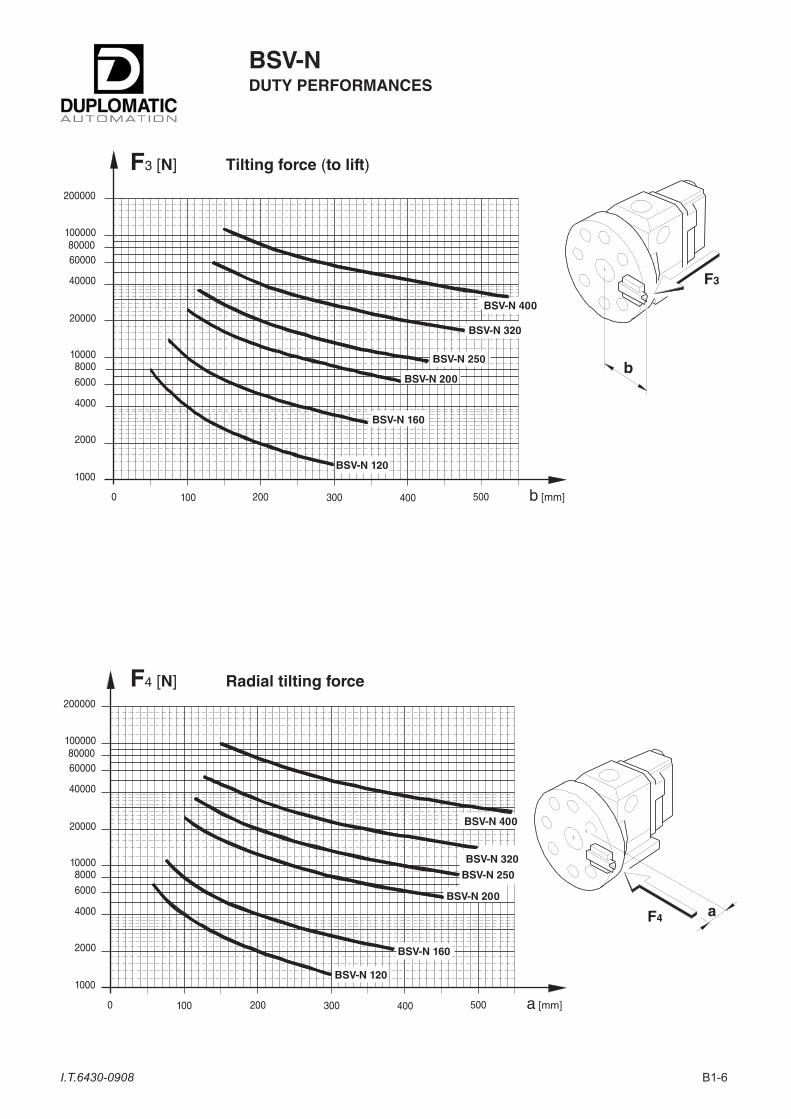
F3 [N] Tilting force (to lift)
F4 [N] Radial tilting force
BSV-NDUTY PERFORMANCES
BSV-N 400
BSV-N 320
BSV-N 250
BSV-N 200
BSV-N 160
BSV-N 120
b [mm]
200000
1000008000060000
40000
20000
100008000
6000
4000
2000
1000
0 100 200 300 400 500
BSV-N 400
BSV-N 320
BSV-N 250
BSV-N 200
BSV-N 160
BSV-N 120
a [mm]
200000
1000008000060000
40000
20000
100008000
6000
4000
2000
1000
0 100 200 300 400 500
F3
b
F4 a

B1-7I.T.6430-0908
S: CHIP CROSS-SECTION (max) for steel R = 600 N/mm2 Ks = 2.200 N/mm2
N: POWER (max) for Vt = 200 m/min
• For any material with different Ks: Sx = S X 2.200
Kx
BSV-NPARAMETERS FOR TURRET SELECTION
BSV-N 400
BSV-N 320
BSV-N 250
BSV-N 200
BSV-N 160
BSV-N 120
b [mm]
1008060
40
20
108
6
4
2
10,8
0 100 200 300 400 500
0,60,5
300
100
5040
30
20
10
5
150
N[kW]
S[mm2]
b
• For different cutting speeds: Nx = N X Vtx
200

B1-8I.T.6430-0908
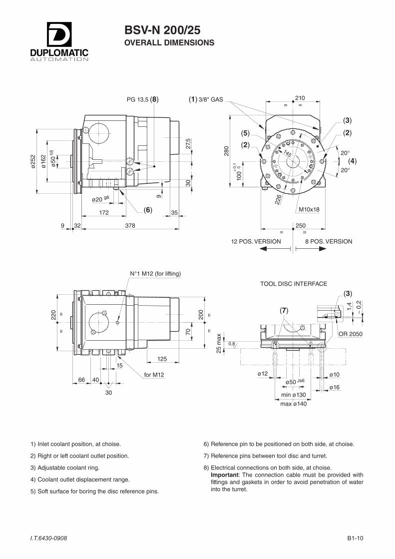
1) Inlet coolant position, at choise.
2) Right or left coolant outlet position.
3) Adjustable coolant ring.
4) Coolant outlet displacement range.
5) Soft surface for boring the disc reference pins.
6) Reference pin to be positioned on both side, at choise.
7) Reference pins between tool disc and turret.
8) Electrical connections on both side, at choise. Important: The connection cable must be provided with
fittings and gaskets in order to avoid penetration of water into the turret.
BSV-N 120/25OVERALL DIMENSIONS
(6)
(4)
(3)
(2)(5)
(2)
=
150
130
=
M8x1533
20
205
7,5
185
90
124
344
152
ø10
2
ø30
h5
266
ø17
5
N°1 M12 (for lifting)
3030
for M8
165
11
50 30
63
20°
20°
==
==
==
(7)
PG 13,5
12 POS. VERSION 8 POS. VERSION
70
ø15 g6
1/4" GAS(1)(8)
(3)
ø8
ø30 Js6
min ø80
max ø85
ø16
ø10
22 m
ax
0,81,
4
~ 0
,2
OR 2050
TOOL DISC INTERFACE
+ 0
,1
0
28
2046
29x4
5°

B1-9I.T.6430-0908
1) Inlet coolant position, at choise.
2) Right or left coolant outlet position.
3) Adjustable coolant ring.
4) Coolant outlet displacement range.
5) Soft surface for boring the disc reference pins.
6) Reference pin to be positioned on both side, at choise.
7) Reference pins between tool disc and turret.
8) Electrical connections on both side, at choise. Important: The connection cable must be provided with
fittings and gaskets in order to avoid penetration of water into the turret.
BSV-N 160/25OVERALL DIMENSIONS
(6)
(4)
(3)
(2)(5)
(2)
=
190
155
=
M8x15
3320
237
7,5
210
120
124
344
149
ø13
2
ø40
h5
266
ø21
5
N°1 M12 (for lifting)
3232
for M10
190
13
58 32
80
20°
20°
==
==
==
(7)
PG 13,5
12 POS. VERSION 8 POS. VERSION
70
ø17 g6
1/4" GAS(1)(8)
(3)
ø10
ø40 Js6
min ø105
max ø110
ø16
ø10
22 m
ax
0,81,
4
~ 0
,2
OR 2050
TOOL DISC INTERFACE
+ 0
,1
0
2825
4629
x45°
B1-10I.T.6430-0908
1) Inlet coolant position, at choise.
2) Right or left coolant outlet position.
3) Adjustable coolant ring.
4) Coolant outlet displacement range.
5) Soft surface for boring the disc reference pins.
6) Reference pin to be positioned on both side, at choise.
7) Reference pins between tool disc and turret.
8) Electrical connections on both side, at choise. Important: The connection cable must be provided with
fittings and gaskets in order to avoid penetration of water into the turret.
BSV-N 200/25OVERALL DIMENSIONS
(6)
(4)
(3)
(2)(5)
(2)
=
226
210
=
M10x18
70
280
9
250
145
200
378
172
ø16
2
ø50
h5
329
ø25
2
N°1 M12 (for lifting)
30
for M12
220
15
66 40
100
20°
20°
==
==
==
(7)
PG 13,5
12 POS. VERSION 8 POS. VERSION
125
ø20 g6
3/8" GAS(1)(8)
(3)
ø12ø50 Js6
min ø130
max ø140
ø16
ø10
25 m
ax
0,81,
4
~ 0
,2
OR 2050
TOOL DISC INTERFACE
+ 0
,1
0
35
3027
,5
B1-11I.T.6430-0908
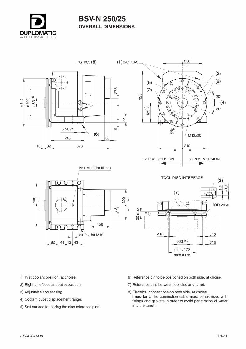
1) Inlet coolant position, at choise.
2) Right or left coolant outlet position.
3) Adjustable coolant ring.
4) Coolant outlet displacement range.
5) Soft surface for boring the disc reference pins.
6) Reference pin to be positioned on both side, at choise.
7) Reference pins between tool disc and turret.
8) Electrical connections on both side, at choise. Important: The connection cable must be provided with
fittings and gaskets in order to avoid penetration of water into the turret.
BSV-N 250/25OVERALL DIMENSIONS
(6)
(4)
(3)
(2)(5)
(2)
=
280
250
=
M12x20
70
325
9
310
182
200
378
210
ø20
2
ø63
h5
3210
ø31
0
N°1 M12 (for lifting)
for M16
280
20
82 44 43 43
125
20°
20°
==
==
==
(7)
PG 13,5
12 POS. VERSION 8 POS. VERSION
125
ø26 g6
3/8" GAS(1)(8)
(3)
ø16
ø63 Js6
min ø170
max ø175
ø16
ø10
25 m
ax
0,8
1,4
~ 0
,2
OR 2050
TOOL DISC INTERFACE
+ 0
,1
0
35
35
27,5

B1-12I.T.6430-0908
1) Inlet coolant position, at choise.
2) Right or left coolant outlet position.
3) Adjustable coolant ring.
4) Coolant outlet displacement range.
5) Soft surface for boring the disc reference pins.
6) Reference pin to be positioned on both side, at choise.
7) Reference pins between tool disc and turret.
8) Electrical connections on both side, at choise. Important: The connection cable must be provided with
fittings and gaskets in order to avoid penetration of water into the turret.
BSV-N 320/24OVERALL DIMENSIONS
(6)
(4)
(3)(2)
(5)
(2)
=
341
325
=
M12x22
34
400
12
390
220
276
492
245
ø27
0
ø80
h5
3810
ø39
0
N°2 M16 (for lifting)
for M20
352
96 48 56 48
160
20°
20°
==
==
==
PG 13,5
(7)
12 POS. VERSION 8 POS. VERSION
ø32 g6
3/8" GAS(1)(8)
(3)
ø16
ø80 Js6
min ø170
max ø220
ø32
ø2533 m
ax
0,82,
2
~ 0
,2
OR 3106
TOOL DISC INTERFACE
+ 0
,1
0
80
40
31
352
267
ø13

B1-13I.T.6430-0908
1) Inlet coolant position, at choise.
2) 4 coolant outlet position.
3) Coolant valve. The valve can be fitted on one of the 4 coolant outlet position. The drawing represents how the valve is positioned when the disc is mounted. Without the disc, the valve produtes by 2 ÷ 3 mm is comparison with the position indicated.
4) Coolant outlet displacement range.
5) Soft surface for boring the disc reference pins.
6) Reference pin to be positioned on both side, at choise.
7) Reference pins between tool disc and turret.
8) Electrical connections on both side, at choise. Important: The connection cable must be provided with
fittings and gaskets in order to avoid penetration of water into the turret.
BSV-N 400/20OVERALL DIMENSIONS
(6)
(4)
(5)
(2)
=
325
=
ø3647
8,5
25°
470
410
323
541
308
ø35
5
ø10
0 h5
4712
N°2 M24 (for lifting)
for M24
420
63 60 140
200
28°
==
465==
==
==
PG 13,5
(7)
1/2" GAS(1)
(8)
ø16
ø100 Js6
min ø245
max ø255
ø22
ø11
35 m
ax
0,8
TOOL DISC INTERFACE
+ 0
,1
0
23
42
16
300
M12
ø14
56
11
==
11°
T-Nut M12 DIN 508
(3)

B1-14I.T.6430-0908

B1-15I.T.6430-0908
~ 3
U1V1W1U2V2W2
WIRING Y (380 V)
U1V1W1U2V2W2
WIRING ∆ (220 V)
BSV-NWIRING DIAGRAM
(1) Other voltages on request.(2) The termal detector gives a signal only motor overheating.
WIRING NUMBER
REF. COMPONENT CHARACTERISTICS SIMBOLS COLOUR SIGNALS
1 ELECTRIC MOTOR(three-phase)
(1)
220-380 V 50/60 Hz
For other characteristics see Tab. 1
U1V1W1U2V2W2
WHITEGREENBLACKWHITEGREENBLACK
See Tab. 2
2 THERMAL DETECTOR 135 °C 1,5A 250V 12
BROWNBROWN (2)
3 BRAKE24 V D.C.
BSV-N 120/160 = 8 WBSV-N 200/400 = 12 W
34
GREENGREEN
4 INDEXING SOLENOID 24V D.C.44 W
56
BLUEBROWN
5 INDEXING CONTROL SWITCH24V D.C. ± 10%200 mA (load)
OUTPUT-PNP-NO
789
BROWNBLACKBLUE
+ V D.C.
EXIT
0 V D.C.
6 LOCKING CONTROL SWITCH7
109
BROWNBLACKBLUE
+ V D.C.
EXIT
0 V D.C.
7 ANGULAR POSITION TRANSMITTER(ABSOLUTE)
24V D.C. ± 10%350 mA (supply)50 mA/exit (load)
OUTPUT-PNP
79
111213141516
BROWNBLUEWHITEYELLOWGREENVIOLETBLACKPINK
+ V D.C.0 V D.C.Bit 1Bit 2Bit 3Bit 4StrobeParity check
GREEN / YELLOW PE
4
3
5 1 2 3
7
6
~
ELECTRIC MOTOR CHARACTERISTICS Tab. 1 ELECTRIC MOTOR'S WIRING (1) Tab. 2
Turret size Minimum required power Short circuit power
BSV-N 120/160 KVA 1,10 KVA 1,60
BSV-N 200/250 KVA 1,80 KVA 2,80
BSV-N 320/400 KVA 2,60 KVA 3,80
B1-16I.T.6430-0908
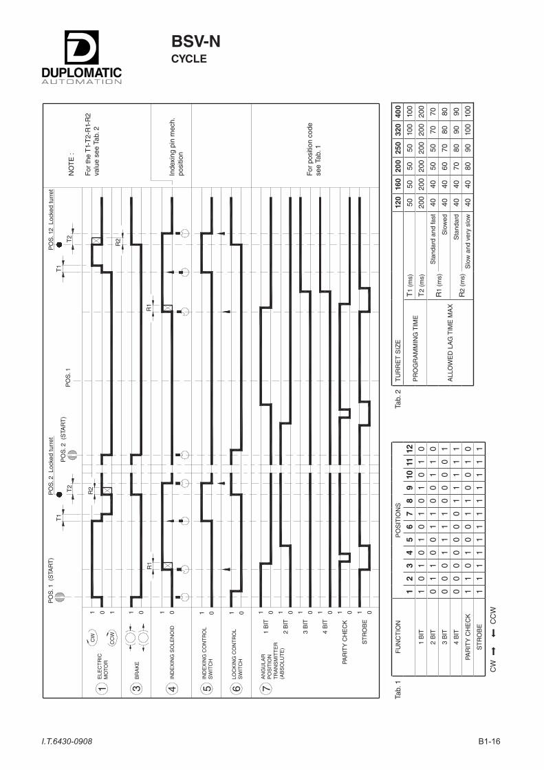
BSV-NCYCLE
Tab.
1F
UN
CT
ION
PO
SIT
ION
S
12
34
56
78
910
1112
1 B
IT1
01
01
01
01
01
02
BIT
01
10
01
10
01
10
3 B
IT0
00
11
11
00
00
14
BIT
00
00
00
01
11
11
PAR
ITY
CH
EC
K1
10
10
01
10
01
0S
TR
OB
E1
11
11
11
11
11
1
CW
C
CW
Tab.
2T
UR
RE
T S
IZE
120
160
200
250
320
400
PR
OG
RA
MM
ING
TIM
ET
1 (m
s)50
5050
5010
010
0
T2
(ms)
200
200
200
200
200
200
ALL
OW
ED
LA
G T
IME
MA
X
R1
(ms)
Sta
ndar
d an
d fa
st40
4050
5070
70
Slo
wed
4040
6070
8080
R2
(ms)
Sta
ndar
d40
4070
8090
90
Slo
w a
nd v
ery
slow
4040
8090
100
100
1 5 6 7
CC
W
CW
01
PO
S. 1
(S
TAR
T)
ELE
CT
RIC
MO
TOR
1
AN
GU
LAR
PO
SIT
ION
TR
AN
SM
ITT
ER
(AB
SO
LUT
E)
1 B
IT
2 B
IT
3 B
IT
4 B
IT
PAR
ITY
CH
EC
K
ST
RO
BE
PO
S. 2
(S
TAR
T)
R1
R2
R1
T1
T1
PO
S. 1
2 L
ocke
d tu
rret
NO
TE
:
For
the
T1-
T2-
R1-
R2
valu
e se
e Ta
b. 2
Inde
pin
mec
h.po
sitio
n
For
pos
ition
cod
ese
e Ta
b. 1
01B
RA
KE
3
01
IND
EX
ING
SO
LEN
OID
4
01IN
DE
XIN
G C
ON
TR
OL
SW
ITC
H
01LO
CK
ING
CO
NT
RO
LS
WIT
CH
01 01 01 01 01 01
T2
PO
S. 2
Loc
ked
turr
et
PO
S. 1
T2
R2

B1-17I.T.6430-0908
1. – SignalsTo get a change of positions on the BSV-N turrets, the con-trol equipment (usually a N.C. equipment) must control the components mentioned below according to a well defined sequence (see wiring diagram on page 15).• Motor (1)• Brake (3)• Indexing solenoid (4)The following output signals from the turret are provided for driving the positioning cycle:– Angular position given by the angular position transmitter (7)– Indexing control switch (5)– Locking control switch (6).
1. – Description of the operating sequenceThis description refers to sequence cycle: the first part gives the sequence to pass from position 1 to position 2 with clockwise rotation, the second part gives the sequence to pass from position 2 to position 12 with counterclockwise rotation.As indicated by the cycle, the controls are to be performed according with the following sequence:
• De-energize the brake (3) and start motor rotation in the desired direction.• If, as in the case shown by the diagram, the next position (pos. 2) is the Stop position, when the strobe signal reached a zero level, the solenoid (4) is to be energized.In case of passage from position 2 to position 12, wait for the reading signaling the passage on pos. 1 then, since the next one is the Stop position, wait until the next strobe signal reaches a zero level and (at that time only) energize the solenoid (4).N.B.: The maximum lag time between the reading of the strobe signal and the excitation of the solenoid (4) cannot exceed the R1 values indicated in the table.• The turret goes on rotating until the indexing pin, pushed by the solenoid (4), enters into the mechanical stop slot.This movement is detected by the sensor (5) which must immediately stop the motor that, once expired the T1 time will re-start rotating in the opposite direction.• During this phase the turret is locking and its locked position is detected by the sensor (6) and this signal is used to stop the motor (1). The maximum lag time between the signal of the sensor and the stopping of the motor must never exceed the R2 value shown in the table. At this point the machine can be started, in order to go on working.• The solenoid (4) is to be de-energized after the expiration of the T2 lag time starting from the moment when the sensor (6) signal is read.
N.B.: The T1, T2, R1, R2 times must be understood as real times execution of the controls and the signals checked on the terminal board of the turret.For an accurate detection and measurement of the above mentioned values it is advisable to use adeguate instru-mentation such as an oscilloscope with memory and current sensing devices.
(*) See tab. 2 sheet 16 (Cycle).
BSV-NCYCLE DESCRIPTIONS
Flow chart
TURRETSTART CYCLE
DE-ENERGIZE BRAKEAND SET ROTATION
1 BEFORE GOAL POSITION-STROBE
SET INDEXmax. allowed lag time
R1 = (*)
INDEX CONTROLSWITCH = 1
STOP ROTATION
SET TIMER T1 (*)
DELAY TIMER T1EXPIRED
LOCKING CONTROLSWITCH = 1
SET REVERSEROTATION
CONCIDENTPOSITION
START TOTHE MACHINE WORK
STOP MOTORmax. allowed lag time
R2 = (*)
SET BRAKE
YES
NO10
YES
NO
YES
NO
NO
YES
YES NO
YES
FAULT

B1-18I.T.6430-0908
"BSV-N*" turrets have been designed for modular fitting onto the different driven tool systems.
BS*-DT• With ODT-N driven tool device.
• Tool coupling according to DIN 1809.
• Tool disc with axial seats.
• Front machining.
For further information please contact our Technical Dept.
BS*-TR• With IDT-R driven tool device.
• Tool disc with radial seats.
• Front machining.
NOTE: Front and back machining for sub-splinde machines is also available on request.
DRIVEN TOOLS SYSTEM
10 ; 60
10 ; 60
BSV-N
"PA" VERSION TURRETS (with axial throught-bore)
Turret sizeBSV-N
120BSV-N
160BSV-N
200BSV-N
250BSV-N
320BSV-N
400
ø D 20 20 28 28 28 60
A 370 370 413 413 530 588
A
øD

B1-19I.T.6430-0908
For other information see the Technical Information UCN-*.
UCN CONTROL UNIT
The UCN control unit manages the moving cycle of BSV-N turret in a simple and optimized way: simple and optimized software; no memory positions are occupied in the machine control; automatic chose of the shortest path; steady monitored for faults.
BSV-N
(1) From 20 to 29 the performance and the overall dimensions do not change.
SERIE 20 ÷ 29 (1)
POSITIONS CODE
Nr. 8 Pos. 8
Nr. 12 Pos. 12
SIZE CODE
120 120
160 160
200 200
250 250
320 320
400 400
BSV-N * - * - * /2* - * - * - ( * )
IDENTIFICATION CODE
OPTIONALS
AXIAL THROUGH BORE CODE
Without (Standard) —
With (Optional) PA
MOTOR VOLT. and FREQUENCY
220-380 220-380 V - 50/60 Hz
230-400 230-400 V - 50/60 Hz
400-440 400-440 V - 50/60 Hz
CODE FREQUENCY and INERTIA
50 H 50 Hz Fast
60 H 60 Hz Fast
50 50 Hz Standard
60 60 Hz Standard
50 L 50 Hz Slow
60 L 60 Hz Slow
50 LL 50 Hz Very slow
60 LL 60 Hz Very slow

DUPLOMATIC AUTOMATION S.r.l.20025 LEGNANO (MI) - ITALY
P.LE BOZZI, 1PHONE 0331/472111
FAX 0331/455161
e-mail: [email protected]
come visit Duplomatic homepage:www.duplomaticautomation.com