bt505: biosensors - virtual university of pakistan · bt505: biosensors introduction to biosensors...
TRANSCRIPT

BT505: Biosensors
Introduction to biosensors
A biosensor is a device that measures biological or chemical reactions by generating signals proportional to the concentration of an analyte in
the reaction. Biosensors are employed in applications such as disease monitoring, drug discovery, and detection of pollutants, disease-causing
micro-organisms and markers that are indicators of a disease in bodily fluids (blood, urine, saliva, sweat). Analyte: A substance of interest that
needs detection. For instance, glucose is an ‘analyte’ in a biosensor designed to detect glucose.
Features of a biosensor
There are certain static and dynamic attributes that every biosensor possesses. The optimisation of these properties is reflected on the
performance of the biosensor.
Selectivity
Selectivity is perhaps the most important feature of a biosensor. Selectivity is the ability of a bioreceptor to detect a specific analyte in a sample
containing other admixtures and contaminants. The best example of selectivity is depicted by the interaction of an antigen with the antibody.
Classically, antibodies act as bioreceptors and are immobilised on the surface of the transducer. A solution (usually a buffer containing salts)
containing the antigen is then exposed to the transducer where antibodies interact only with the antigens. To construct a biosensor, selectivity is
the main consideration when choosing bioreceptors.
Reproducibility
Reproducibility is the ability of the biosensor to generate identical responses for a duplicated experimental set-up. The reproducibility is
characterised by the precision and accuracy of the transducer and electronics in a biosensor. Precision is the ability of the sensor to provide alike
results every time a sample is measured and accuracy indicates the sensor's capacity to provide a mean value close to the true value when a
sample is measured more than once. Reproducible signals provide high reliability and robustness to the inference made on the response of a
biosensor.
Stability
Stability is the degree of susceptibility to ambient disturbances in and around the biosensing system. These disturbances can cause a drift in the
output signals of a biosensor under measurement. This can cause an error in the meas-ured concentration and can affect the precision and
accuracy of the biosensor. Stability is the most crucial feature in applications where a biosensor requires long incubation steps or continuous
monitoring. The response of transducers and electronics can be temperature-sensitive, which may influence the stability of a biosensor.
Therefore, appropriate tuning of electronics is required to ensure a stable response of the sensor. Another factor that can influence the stability is
the affinity of the bioreceptor, which is the degree to which the analyte binds to the bioreceptor. Bioreceptors with high affinities encourage
either strong electrostatic bonding or covalent linkage of the analyte that fortifies the stability of a biosensor. Another factor that affects the
stability of a measurement is the degradation of the bioreceptor over a period of time.
Sensitivity
The minimum amount of analyte that can be detected by a biosensor defines its limit of detection (LOD) or sensitivity. In a number of medical
and environmental monitoring applications, a biosensor is required to detect analyte concentration of as low as ng/ml or even fg/ml to confirm
the presence of traces of analytes in a sample. For instance, a prostate-specific antigen (PSA) concentration of 4 ng/ml in blood is associated
with prostate cancer for which doctors suggest biopsy tests. Hence, sensitivity is considered to be an important property of a biosensor.
Linearity
Linearity is the attribute that shows the accuracy of the measured response (for a set of measurements with different concentrations of analyte) to
a straight line, mathematically represented as y=mc, where c is the concentration of the analyte, y is the output signal, and m is the sensitivity of
the biosensor. Linearity of the biosensor can be associated with the resolution of the biosensor and range of analyte concentrations under test.
The resolution of the biosensor is defined as the smallest change in the concentration of an analyte that is required to bring a change in the
response of the biosensor. Depending on the application, a good resolution is required as most biosensor applications require not only analyte
detection but also measurement of concentrations of analyte over a wide working range. Another term associated with linearity is linear range,
which is defined as the range of analyte concentrations for which the biosensor response changes linearly with the concentration.
Components of biosensor
• Bioreceptor: A molecule that specifically recognises the analyte is known as a bioreceptor. Enzymes, cells, aptamers, deoxyribonucleic
acid (DNA) and antibodies are some examples of bioreceptors. The process of signal generation (in the form of light, heat, pH, charge or
mass change, etc.) upon interaction of the bioreceptor with the analyte is termed bio-recognition.

• Transducer: The transducer is an element that converts one form of energy into another. In a biosensor the role of the transducer is to
convert the bio-recognition event into a measurable signal. This process of energy conversion is known as signalisation. Most
transducers produce either optical or electrical signals that are usually proportional to the amount of analyte–bioreceptor interactions.
• Electronics: This is the part of a biosensor that processes the transduced signal and prepares it for display. It consists of complex
electronic circuitry that performs signal conditioning such as amplification and conversion of signals from analogue into the digital form.
The processed signals are then quantified by the display unit of the biosensor.
• Display: The display consists of a user interpretation system such as the liquid crystal display of a computer or a direct printer that
generates numbers or curves understandable by the user. This part often consists of a combination of hardware and software that
generates results of the biosensor in a user-friendly manner. The output signal on the display can be numeric, graphic, tabular or an
image, depending on the requirements of the end user.
Micro-Electro-Mechanical Systems, or MEMS, is a technology that in its most general form can be defined as miniaturized mechanical and
electro-mechanical elements (i.e., devices and structures) that are made using the techniques of microfabrication. The critical physical
dimensions of MEMS devices can vary from well below one micron on the lower end of the dimensional spectrum, all the way to several
millimeters. Likewise, the types of MEMS devices can vary from relatively simple structures having no moving elements, to extremely
complex electromechanical systems with multiple moving elements under the control of integrated microelectronics. The one main criterion
of MEMS is that there are at least some elements having some sort of mechanical functionality whether or not these elements can move. The
term used to define MEMS varies in different parts of the world. In the United States they are predominantly called MEMS, while in some
other parts of the world they are called “Microsystems Technology” or “micromachined devices”.
While the functional elements of MEMS are miniaturized structures, sensors, actuators, and microelectronics, the most notable (and perhaps
most interesting) elements are the microsensors and microactuators. Microsensors and microactuators are appropriately categorized as
“transducers”, which are defined as devices that convert energy from one form to another. In the case of microsensors, the device typically
converts a measured mechanical signal into an electrical signal.
Types of sensor
Electrochemical Biosensor
Electrochemical Biosensors is a simple device. It measures the measurement of electronic current, ionic or by conductance changes carried by bio-electrodes.
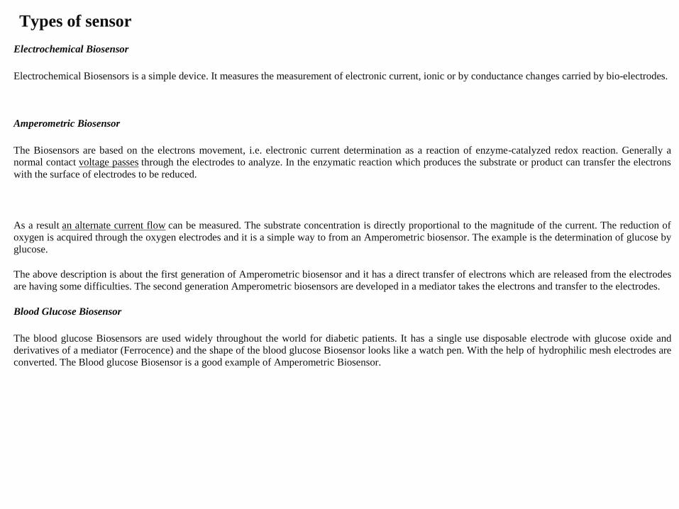
Amperometric Biosensor
The Biosensors are based on the electrons movement, i.e. electronic current determination as a reaction of enzyme-catalyzed redox reaction. Generally a
normal contact voltage passes through the electrodes to analyze. In the enzymatic reaction which produces the substrate or product can transfer the electrons
with the surface of electrodes to be reduced.
As a result an alternate current flow can be measured. The substrate concentration is directly proportional to the magnitude of the current. The reduction of
oxygen is acquired through the oxygen electrodes and it is a simple way to from an Amperometric biosensor. The example is the determination of glucose by
glucose.
The above description is about the first generation of Amperometric biosensor and it has a direct transfer of electrons which are released from the electrodes
are having some difficulties. The second generation Amperometric biosensors are developed in a mediator takes the electrons and transfer to the electrodes.
Blood Glucose Biosensor
The blood glucose Biosensors are used widely throughout the world for diabetic patients. It has a single use disposable electrode with glucose oxide and
derivatives of a mediator (Ferrocence) and the shape of the blood glucose Biosensor looks like a watch pen. With the help of hydrophilic mesh electrodes are
converted. The Blood glucose Biosensor is a good example of Amperometric Biosensor.

Potentiometric Biosensor
In this type of Biosensors changes the concentration of ionic is determined by the ion-selective electrodes in this pH electrodes are used most commonly.
Hence a large amount of enzymatic reactions is involved in the release of hydrogen ions. Ammonia-selective and Corbondioxide selective electrodes are
some other important electrodes.
The Potentiometric electrode and the reference electrode can be measured with the help of potential difference and it is directly proportional to the substrate
concentration. The Potentiometric Biosensors is the sensitivity of enzymes to ionic concentration like H+ and NH+4
The ion- selective field effect transistors are lower price devices. It can be used in the miniaturization of Potentiometric Biosensors. The example of the
ISFET Biosensor is to monitor intra-myocardial for open heart surgery.
Conduct Metric Biosensor
In the biological system there are several reactions that change the ionic species. The electronic conductivity can be measured with the help of an ionic
species. The example of the conduct metric Biosensor is the urea Biosensor which utilizing the immobilized areas. The following reactions show the urea
catalyses.
The given reaction is associated with the drastic alteration in ionic concentration and they are used for the monitoring urea concentration. In generally during
the dialysis and renal surgery the urea Biosensor is very useful.
Thermometric Biosensor
There are many more biological reactions are connected with the production of heat and it forms the basis of thermometric Biosensors. The diagram shows
the representation of a thermal Biosensor. The diagram consists of a heat insulated box fixed with heat exchange.
Optical Biosensors
The optical Biosensor is a device, it utilizes the principle of optical measurements like fluorescence, absorbance and etc. They used in fiber optics and
Optolelectronic transducers. The optical Biosensors are safe for non electrical remote sensing of materials. In the transducer elements primarily optical
Biosensors involves in the enzymes and antibodies. Usually the Biosensors is not required any reference sensors and the comparative signals are generated by
using the sampling sensor. The important Biosensors is described briefly.

Fiber Optic Lactate Biosensor
The working of the fiber optic lactate Biosensor is based on the measurement of change in oxygen concentration, molecular by identifying the effects of
oxygen in fluorescent dye. The following reaction is reduced by the enzyme lactate mono-oxygenase. The oxygen depends on the amount of fluorescence
generated by the dyed film this is because of oxygen has a reducing effect on the fluorescence. In the reaction mixture the concentration of lactate is
increased, oxygen is utilized and as a result, there is a proportional decrease in the quenching effect. Hence there is an increase in the fluorescence output
can be measured.
Optical Biosensors for Blood Glucose
For the diabetes patients the blood glucose is more important to monitor. In this simple technique is used, i.e. Paper strips saturated with the reagents it
contains glucose oxide, Horseradish Peroxidase and a Chrmogen. The following reactions take place. Using the portable reflectance meter it can measure
the intensity of the colour of the dye. In the world wide the glucose strip industry is very high. The calorimetric test strips of cellulose covered with the
suitable enzymes and reagents are in use for the view of more blood and the urine parameters. The other optical fiber Biosensors are used in the devices of
optical Biosensing it measures the p CO2 and in critical care and in surgical monitoring.
Piezoelectric Biosensors
The principle of piezoelectric Biosensor is used in sound vibrations, hence it is called acoustic Biosensors. The basics of the Biosensors are formed by the
piezoelectric crystals and the characteristic frequencies are trembling with the crystals of positive and negative charge. By using the electronic devices we
can measure the certain molecules on the crystal surface and alters the response frequencies using these crystals we can attaché the inhibitors. The
Biosensors for cocaine in the gas phase has been developed by attaching the antibodies cocaine to the surface of the crystal.
Immuno–Biosensors
The immune Biosensors work on the principle of immunological specificity and mostly coupled with measurement on the Potentiometric Biosensors. There
are different configurations of probabilities for immune Biosensors some of them are given below and the figure shows the description
The immobilized antibody can directly combine through the antigen.
MEM System
MEMS are the abbreviation for Micro Electro Mechanical Systems. These can be components like micro sensors or micro motors, but also
micro sensors or micro measurement devices. The special adventage of this technology is, that mechanical parts as well as electronic circuits can
be manufactured from the same material and in the same substrate, which is usually silicon . Silicon wafers are already used for long time as a
material for the production of integrated circuits. Meanwhile it became possible to integrate mechanical and moving parts as well as membranes,
measurement pins or other structures directly into the silicon, which serves also as a substrate for the electronic compounds. This could be
achieved mainly by improved methods for etching and texturing of silicon wafers and bond technology for connecting two silicon wafers. The
advantage is predictable: Very small mechanical parts can be produced including their electrical control or evaluation system. Basically, the
same machines and the same equipment are used for its production that is also used for manufacturing semiconductor circuits. However the
specifications and requirements are less strict, minimum resolution and smallest line width are larger compared to needs in the semiconductor
industry? Furthermore such MEMS parts are often produced in small production volume, which requires the dedication of flexible, small and
cost effective equipment. Quite often even equipment with manual loading is requested. Manufacturing equipment can therefore be designed
simpler and cheaper, which helps to reduce the investment budget of a MEMS factory and allows then also smaller companies to enter this
market. This circumstances lead in the past years to a strong increase of new companies, manufacturing parts or sensors in MEMS-technology.
Many manufacturers of semiconductor equipment adapted meanwhile to this trend and offer now equipment, customized for MEMS production.
Material removal by etching in wet etching or plasma etching equipment
Texturing MEMS components is mainly done by etching quite often by plasma etching or dry etching. In a low pressure chamber a plasma is
generated which contains highly reactive chlorous or fluorous radicals. These radicals are accelerated towards the silicon wafer, where they react
with silicon and volatile compounds are generated. Material is removed. For manufacturing mechanical structures in a MEMS compound it is
often necessary to etch deep trenches. The company of SNTEK is manufacturing such plasma etchers, which can etch also deep trenches.
Models for manual and automatic loading cassette to cassette are available.
PECVD or LPCVD layer deposition
For building electro mechanical micro system, it is also necessary to deposit conductive or dielectric layers. Common layers are poly-
silicon, silicon oxide or silicon nitride. It is necessary to control the tension in the layers, which is generated by different lattice constants of
substrate and deposited layer.
Deposition can be achieved by plasma enhanced chemical vapor depostion PECVD from the gas phase. Using very reactive moleculs from the
plasma, the deposition temperature can be kept rather low. PECVD equipment looks similar to plasma etching equipment.
Alternatively low pressure chemical vapor depostion LPCVD can be used, where the reaction is driven thermally by high temperature instead of
using a plasma. Equipment for this process is called LPCVD furnace. The high temperature is a handicap for some products, but results on the
other hand in more homogenious layers. A manufacturer of such LPCVD furnaces is the company of Koyo Thermo Systems. Small furnaces for
a capacity of 25 wafers and manual loading are available as well as equipment with medium capacity or fully automatic systems for mass
production.

Applications are developed where miniaturization is beneficial: Consumer products Aerospace Automotive Biomedical Chemical Optical
displays Wireless and optical communications Fluidics
Types of MEMS
Devices…. Pressure sensors, Accelerometers Micromirrors, Gear Trains, Miniature robots, Fluid pumps, Microdroplet generators, Optical scanners,
Probes (neural, surface), Analyzers, Imagers
BioMEMS applications
In this section, a few representative BioMEMS applications are presented. A survey of all products available on the market is beyond the
scope of this article.
a) MEMS Pressure Sensors The first MEMS devices to be used in the biomedical industry were reusable blood pressure sensors in the
1980s. MEMS pressure sensors have the largest class of applications including disposable blood pressure, intraocular pressure (IOP),
intracranial pressure (ICP), intrauterine pressure, and angioplasty. Some manufacturers of MEMS pressure sensors for biomedical applications
include CardioMEMS, Freescale semiconductors, GE sensing, Measurement Specialties, Omron, Sensimed AG and Silicon Microstructures.
According to World Health Organization (WHO), Glaucoma is the second leading cause of blindness in the world after cataracts. MEMS
implantable pressure sensors are used for continuous IOP monitoring in Glaucoma patients. A normal eye maintains a positive IOP in the range
of 10-22 mmHg. Abnormal elevation (> 22 mmHg) and fluctuation of IOP are considered the main risk factors for glaucoma. Glaucoma, often
without any pain or significant symptoms, can cause an irreversible and incurable damage to the optic nerve. This initially affects the peripheral
vision and possibly leads to blindness without timely lifetime treatment. Therefore, it is critical to accurately monitor IOP and provide prompt
treatments at the early stages of glaucoma development. Sensimed’s TriggerfishTM implantable MEMS IOP sensor is shown in Figure 5. It
consists of a disposable contact lens with a MEMS strain-gage pressure sensor element, an embedded loop antenna (golden rings), and an ASIC
microprocessor (2mmx2mm chip). The MEMS sensor includes a circular active outer ring and passive strain gages to measure corneal curvature
changes in response to IOP. The loop antenna in the lens receives power from the external monitoring system and sends information back to the
system.

b) MEMS Inertial Sensors MEMS accelerometers are used in defibrillators and pacemakers. Some patients exhibit unusually fast or
chaotic heart beats and thus are at a high risk of cardiac arrest or a heart attack. An implantable defibrillator restores a normal heart rhythm by
providing electrical shocks to the heart during abnormal conditions. Some peoples’ hearts beat too slowly, and this may be related to the natural
aging process or a genetic condition. A pacemaker maintains a proper heart beat by transmitting electrical impulses to the heart. Conventional
pacemakers were fixed rate. Modern pacemakers employ MEMS accelerometers and are capable of adjusting heart rate in accordance with the
patient’s physical activity. Medtronic is a leading manufacturer of MEMS based defibrillators and pacemakers. Figure 6 shows a MEMS
accelerometer-based Medtronic’s SureScanTM pacemaker and implantation of a pacemaker inside the body next to the heart. This pacemaker is
designed to be compatible with magnetic resonance imaging (MRI).
MEMS inertial sensors (accelerometers and gyroscopes) were employed to develop one of the most unique wheelchairs, the
iBOTTM Mobility system, shown in Figure 7. A combination of multiple inertial sensors in this system enables the user to operate the wheelchair
and lift to a standing height just balancing on two wheels. This allows the wheelchair user to interact with others face-to-face. The
iBOTTM system was developed by Dean Kamen in a partnership between DEKA and Johnson and Johnson’s Independence Technology division.
Unfortunately, it is no longer available for sale from Independence Technology. Another related example is the Segway PT, a two-wheeled, self-
balancing, battery-powered electric vehicle, also invented by Dean Kamen. It is produced by Segway Inc. of New Hampshire, USA.
c) MEMS Hearing-Aid Transducer A hearing-aid is an electroacoustic device used to receive, amplify and radiate sound into the ear. The
goal of a hearing aid is to compensate for the hearing loss and thus make audio communication more intelligible for the user. In the US, hearing
aids are considered medical devices and are regulated by the FDA. According to NIH, approximately 17 percent (36 million) of American adults
report some degree of hearing loss. There is a strong relationship between age and reported hearing loss. Also, about 2 to 3 out of every 1,000
children in the United States are born deaf or hard-of-hearing.
According to statistics, 80% of those who could benefit from a hearing-aid chose not to use one. The reasons include reluctance to
recognize hearing loss and social stigma associated with common misconceptions about wearing hearing aids. Thus, it is highly desirable to
miniaturize hearing-aids without compromising performance. MEMS technology enables reduction of form factor, cost, and power consumption
compared to conventional hearing-aid solutions. Figure 8 shows Analog Devices small size (7.3 mm3) MEMS microphone suitable for hearing-
aid applications.
d) Microfluidics for diagnostics Microfluidics involve movement, mixing and control of small volumes (nanoliters) of fluids. A
typical microfluidic system is comprised of needles, channels, valves, pumps, mixers, filters, sensors, reservoirs, and dispensers.
Microfluidics enable bedside or at the point-of-care (POC) medical diagnosis. Especially, POC diagnosis is important in developing
countries where access to centralized hospitals is limited and expensive. A POC diagnostic microfluidic system uses bodily fluids (saliva,
blood, or urine samples) to perform sample preconditioning, sample fractionation, signal amplification, analyte detection, data analysis,
and results display. In 1985, Unipath introduced the first POC microfluidic device, ClearBlueTM, for pregnancy test from urine sample
and is still available on the market. Recently, a comprehensive review article on the commercialization of microfluidic devices for POC
diagnostics was published by Chin et al. [4].
One of the world’s most significant public health challenges, particularly in low- and middle- income countries, remains to be
HIV/AIDS. According to WHO, 34 million people are living with HIV, and around 7 million eligible people are waiting for antiretroviral
therapy. POC diagnosis is very crucial for the enumeration of absolute numbers of T-helper cells, commonly referred to as a CD4 count, for
monitoring the course of immunosuppression caused by HIV and the initiation of antiretroviral therapy. The Alere Pima™ CD4 test system,
shown in Figure 9, offers a revolutionary POC solution by providing an absolute CD4 count from either a fingerstick or a venous whole blood
sample. The test requires approximately 25 microliters of whole blood sample to be loaded into the cartridge capillary. All test reagents are
sealed within the disposable cartridge. On insertion of the cartridge into the analyzer, the test process automatically begins and displays direct
CD4 measurement within 20 minutes.
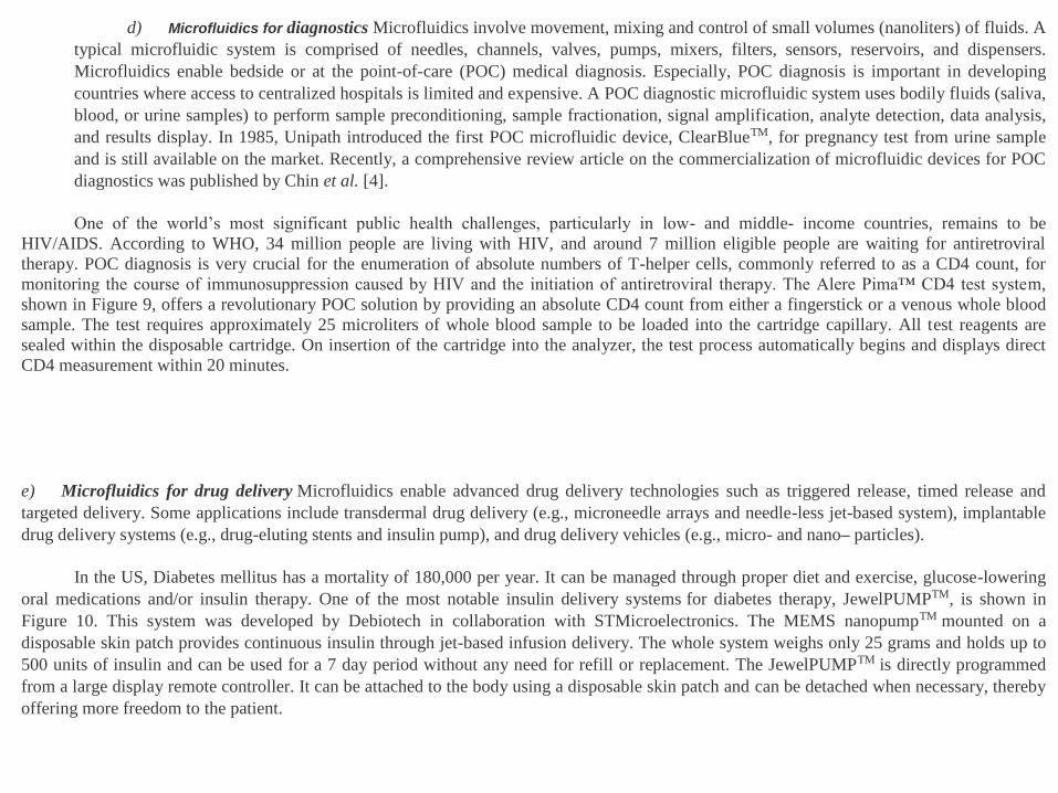
e) Microfluidics for drug delivery Microfluidics enable advanced drug delivery technologies such as triggered release, timed release and
targeted delivery. Some applications include transdermal drug delivery (e.g., microneedle arrays and needle-less jet-based system), implantable
drug delivery systems (e.g., drug-eluting stents and insulin pump), and drug delivery vehicles (e.g., micro- and nano– particles).
In the US, Diabetes mellitus has a mortality of 180,000 per year. It can be managed through proper diet and exercise, glucose-lowering
oral medications and/or insulin therapy. One of the most notable insulin delivery systems for diabetes therapy, JewelPUMPTM, is shown in
Figure 10. This system was developed by Debiotech in collaboration with STMicroelectronics. The MEMS nanopumpTM mounted on a
disposable skin patch provides continuous insulin through jet-based infusion delivery. The whole system weighs only 25 grams and holds up to
500 units of insulin and can be used for a 7 day period without any need for refill or replacement. The JewelPUMPTM is directly programmed
from a large display remote controller. It can be attached to the body using a disposable skin patch and can be detached when necessary, thereby
offering more freedom to the patient.

f) Micromachined needles Micromachining enables fabrication of needles smaller than 300 µm, which is the limit of conventional
machining methods. Typically, the length of the MEMS-based microneedles is less than 1 mm. Microneedles have been used for drug delivery,
bio-signal recording electrodes, blood extraction, fluid sampling, cancer therapy, and microdialysis. Frequently, microneedles are integrated and
used in conjunction with microfluidic systems. Solid and hollow microneedles have been fabricated out of silicon, glass, metals, and polymers
using micromachining processes. Microneedles have been demonstrated with various body shapes (cylindrical, canonical, pyramid, candle,
spike, spear, square, pentagonal, hexagonal, octagonal and rocket shape) and tip shapes (volcano, snake fang, cylindrical, canonical, micro-
hypodermis and tapered). It shows solid microneedles fabricated by reactive ion etching of silicon and hollow microneedles fabricated by laser
machining of a polymer.
g) Microsurgical tools Surgery is treatment of diseases or other ailments through manual and instrumental methods. In surgery, the majority
of trauma to the patient is caused by the surgeon’s incisions to gain access to the surgical site. Minimally invasive surgical (MIS) procedure aims
to provide diagnosis, monitoring, or treatment of diseases by performing operations with very small incisions or sometimes through natural
orifices. Advantages of MIS over conventional open surgery includes less pain, minimal injury to tissues, minimal scarring, reduced recovery
time, shorter hospital visits, faster return to normal activities and often lower cost to the patient. Common MIS procedures include angioplasty,
catheterization, endoscopy, laparoscopy, and neurosurgery. MEMS based microsurgical tools have been identified as a key enabling technology
for MIS. It should be noted that some of these feasibility demonstrations have yet to be qualified for clinical applications.
MEMS Sensors
Sensors are a major application for MEMS devices. Three primary MEMS sensors
1 Chemical sensors 2. Inertial sensors (accelerometers, gyroscopes) 3 . MEMS sensors can be used in combinations with other sensors for multisensing
applications. For example, a MEMS can be designed with sensors to measure the flow rate of a liquid sample and at the same time identify any
contaminates within the sample.
How do they work or what is an Ion-Selective Electrode? An Ion Selective Electrode measures the potential of a specific ion in solution. (The
pH electrode is an ISE for the Hydrogen ion.) This potential is measured against a stable reference electrode of constant potential. The potential
difference between the two electrodes will depend upon the activity of the specific ion in solution. This activity is related to the concentration of
that specific ion, therefore allowing the end-user to make an analytical measurement of that specific ion. Several ISE's have been developed for a
variety of different ions.

How Does the mV Reading Correspond to the Concentration? Standard solutions of known concentrations must be accurately prepared. These
solutions are then measured with the pH/mV meter. The mV reading of each solution is noted and a graph of concentration vs. mV reading must
be plotted. Now the unknown solution can be measured. The mV value of the unknown solution is then located on the graph and the
corresponding solution concentration is determined.
Ion Selective Electrodes (including the most common pH electrode) work on the basic principal of the galvanic cell (Meyerhoff and Opdycke).
By measuring the electric potential generated across a membrane by "selected" ions, and comparing it to a reference electrode, a net charge is
determined. The strength of this charge is directly proportional to the concentration of the selected ion. The basic formula is given for the
galvanic cell:
Ecell = Eise - Eref
the potential for the cell is equivalent to the potential of the ISE minus the potential of the reference electrode.
Calibration -- Direct - The electric potentials are determined for a series of standards and a standard curve is developed. Additional analyses are
fit to the standard curve in order to determine concentration. Direct calibration is the most common and easiest way to measure concentrations.
Standard Additions - The use of standard additions (the addition of known amounts of a standard) allows the use of the electrode in very
complex matrices, without the need for direct calibration prior to measurement (Covington).
Titration's - ISEs have also been used as detectors for titration's (Orion). Titration methods use a titrant (such as EDTA) which will
complex or react with the ion to be analyzed. The concentration of the ion in the sample is back calculated from the volume of the titrant
used in the titration.
Membranes -- The nature of the membrane determines the selectivity of the electrode. A membrane is considered to be any material that
separates two solutions. It is across this membrane that the charge develops. The term "membrane" is often confused as implying
permeability. While this is true in many cases, the term here is used denote any material which the charge can develop across (Covington).
Several types of sensing electrodes are commercially available. They are classified by the nature of the membrane material used to construct
the electrode. It is this difference in membrane construction that makes an electrode selective for a particular ion.

1. Polymer Membrane Electrodes (Organic Ion Exchangers and Chelating Agents) -- Polymer membrane electrodes consist of various ion-
exchange materials incorporated into an inert matrix such as PVC, polyethylene or silicone rubber. After the membrane is formed, it is
sealed to the end of a PVC tube. The potential developed at the membrane surface is related to the concentration of the species of interest.
Electrodes of this type include potassium, calcium, chloride, fluoroborate, nitrate, perchlorate, potassium, and water hardness.
2. Solid State Electrodes (Insoluble Conductive Inorganic Salts) -- Solid state electrodes utilize relatively insoluble inorganic salts in a
membrane. Solid state electrodes exist in homogeneous or heterogeneous forms. In both types, potentials are developed at the membrane surface
due to the ion-exchange process. Examples include silver/sulphide, lead, copper (II), cyanide, thiocynate, chloride, and fluoride.
3. Gas Sensing Electrodes -- Gas sensing electrodes are available for the measurement of dissolved gas such as ammonia, carbon dioxide,
nitrogen oxide, and sulfur dioxide. These electrodes have a gas permeable membrane and an internal buffer solution. Gas molecules diffuse
across the membrane and react with a buffer solution, changing the pH of the buffer. The pH of the buffer solution changes as the gas reacts with
it. The change is detected by a combination pH sensor within the housing. Due to their construction, gas sensing electrodes do not require an
external reference electrode.
4. Glass Membrane Electrodes -- Glass membrane electrodes are formed by the doping of the silicon dioxide glass matrix with various
chemicals. The most common of the glass membrane electrodes is the pH electrode. Glass membrane electrodes are also available for the
measurement of sodium ions.
What Type of Equipment is needed for an ISE Measurement? A pH meter that also measures millivolts can be used to interface with an ISE.
Most ISE's are combination electrodes that have the reference electrode built into the body of the ISE, however, some ISE's require a separate
reference electrode. If this is the case, the pH/mV meter must have a pin-connector to connect the reference electrode.
Agitation -- When carrying out selective ion measurements, it is important to have good agitation. This allows a fresh supply of ions to be
exposed to the sensing portion of the ISE. It is best to select a speed that keeps a constant, smooth motion. A turbulent rate should be avoided.
pH Adjustment -- In many cases pH control is necessary for accurate, repeatable measurements. Certain ions exhibit different activity when
different concentrations of hydrogen ions are present in solution. This occurrence will not only alter the potential due to the specific ion that is
measured, it may also allow other ions in solution to become active that otherwise were not. This increased activity from the other ions will
interfere with the ability to evaluate the ion of interest.

Response Time -- ISE's require a much longer time for the readings to stabilize. At least fifteen minutes should be allowed for equilibrium to be
established when measuring standard solutions.
Establishing a Calibration Curve -- It is recommended to use three standard solutions when establishing a calibration curve. To choose the
concentrations of the standard solutions it is helpful to know the approximate values of the unknown solutions. For example, if the unknown
solutions are in the 100 ppm range, the choice of standards may include a 10 ppm, a 100 ppm, and a 1000 ppm solution.
Rinsing -- It is necessary to rinse the ISE between measurements to insure accurate readings. Use a steady stream of deionized or distilled water.
Take care not to rub the electrode with a cloth to dry the probe. It is usually best to "shake off" any excess water. Take care not to hit the probe
against anything while shaking the electrode.
Conditioning -- The ISE needs to remain moist at all times even when not in use. Consult the operator's manual that accompanies the electrode
for details on cleaning, conditioning, and storing the ISE.
General Comments on Ion-Selective Electrodes:
1. Electrodes with a polymer membrane must not come in contact with organic solvents
2. Do not store in water for extended periods—dry before storing
3. Store Combined Ion Selective Electrodes in dilute ISA (ionic strength adjuster) solution—for long term storage, remove reference
solution and store dry.
4. Clean crystal membranes with a mild abrasive, then rinse with water. Toothpaste is an excellent cleaning agent, for fluoride electrodes
use fluoride toothpaste
Gas biosensor
Gas biosensors for detection of vapors of some volatile compounds (SO2, alcohol, formaldehyde, phenol) are reviewed. The enzymes
sulphite oxidase, alcohol oxidase, alcohol dehydrogenase, formaldehyde dehydrogenase and polyphenol oxidase are used in
electrochemical cells separated from the gas phase by a porous membrane, and in microbiosensors with “enzyme gel” deposited onto an
interdigitated gold two-electrode system. A gas biosensor for the vapors of phenolic compounds vapors, comprising an enzyme/gas-
diffusion electrode with tyrosinase enzyme is investigated. The transient amperometric signal and the calibration curves of this gas
biosensor are studied in the presence of phenol, p-cresol and 4-chlorophenol vapors. It is shown that phenol vapor concentrations in the
ppb range are detectable with this type of gas biosensor.

The detection of chemical compounds has been an essential tool for the advance- ment of chemical and biological sciences since their
beginnings. The evolution of modem techniques, like HPLC, GLC, or NMR, with expanded capabilities in terms of precision,
reproducibility and sample handling shows the enormous driving force for the sustained progress in analysis. Within the last two decades
an immense interest has been observed in the use of biological activity in analysis. This line of applied research has led to the concept of
biosensors, defined as devices or arrangements that detect and mea- sure a variety of compounds based on a molecular modification or
interaction brought about by biomolecules with catalytic capabilities. Clearly, biosensors are considered a recent product of
biotechnology, since the progress in this multidis- ciplinary science has resulted in a deeper knowledge of biocatalysis and biological
phenomena in general that will translate into innovative possibilities in analysis. In addition, recent discoveries in the fields of
electronics, electrochemistry and optical transduction will contribute decisively to the future of biosensors. Conse- quently, the
commercial expectations for biosensors are based on their enormous potential as successors to a wide range of current analytical
techniques. The key component of any biosensor is a biological molecule or system, whether in a fairly purified form (enzyme, antibody,
nucleic acid, receptor etc.) or as part of a more complex structure (whole cell, organelle, tissue, etc.). The phenomenon involved is the
specificity of biomolecules to interact selec- tively with a particular compound or group of compounds present in a complex mixture,
even in extremely low concentrations that can reach the ppb range. Once such a selective recognition event takes place it results in a
measurable parameter that has to be amplified to proceed with detection and quantization. The trans- duction stage is crucial to attain the
sensitivity offered by biomolecules and in general can be classified within the following types: amperometric, conductimet- ric,
potentiometric, optical or mass related changes (i.e. vibration frequency in piezolectric crystals)
Solid State biosensor
An ISFET is an ion-sensitive field-effect transistor, that is a field-effect transistor used for measuring ion concentrations in solution; when the
ion concentration (such as H+, see pH scale) changes, the current through the transistor will change accordingly. Here, the solution is used as the
gate electrode. A voltage between substrate and oxide surfaces arises due to an ion sheath
The surface hydrolysis of Si–OH groups of the gate materials varies in aqueous solutions due to pH value. Typical gate materials
are SiO2, Si3N4, Al2O3 and Ta2O5.
The mechanism responsible for the oxide surface charge can be described by the site binding model, which describes the equilibrium between
the Si–OH surface sites and the H+ ions in the solution. The hydroxyl groups coating an oxide surface such as that of SiO2 can donate or accept a
proton and thus behave in an amphoteric way as illustrated by the following acid-base reactions occurring at the oxide-electrolyte interface:

—Si–OH + H2O ↔ —Si–O− + H3O+
—Si–OH + H3O+ ↔ —Si–OH2
+ + H2O
An ISFET's source and drain are constructed as for a MOSFET. The gate electrode is separated from the channel by a barrier which is
sensitive to hydrogen ions and a gap to allow the substance under test to come in contact with the sensitive barrier. An ISFET's threshold
voltage depends on the pH of the substance in contact with its ion-sensitive barrier.
The Electromagnetic Spectrum
The electromagnetic (EM) spectrum is the range of all types of EM radiation. Radiation is energy that travels and spreads out as it goes –
the visible light that comes from a lamp in your house and the radio waves that come from a radio station are two types of electromagnetic
radiation. The other types of EM radiation that make up the electromagnetic spectrum are microwaves, infrared light, ultraviolet light, X-
rays and gamma-rays.
Radio: Your radio captures radio waves emitted by radio stations, bringing your favorite tunes. Radio waves are also emitted by stars and gases
in space.
Microwave: Microwave radiation will cook your popcorn in just a few minutes, but is also used by astronomers to learn about the structure of
nearby galaxies.
Infrared: Night vision goggles pick up the infrared light emitted by our skin and objects with heat. In space, infrared light helps us map
the dust between stars.
Visible: Our eyes detect visible light. Fireflies, light bulbs, and stars all emit visible light.
Ultraviolet: Ultraviolet radiation is emitted by the Sun and are the reason skin tans and burns. "Hot" objects in space emit UV radiation as well.
X-ray: A dentist uses X-rays to image your teeth, and airport security uses them to see through your bag. Hot gases in the Universe also emit X-
rays.
Gamma ray: Doctors use gamma-ray imaging to see inside your body. The biggest gamma-ray generator of all is the Universe.

Xray Application
Discovered in 1901, x-rays have revolutionised the world of modern medicine. In fact, German physicist Wilhelm Conrad Röntgen was even
awarded a Nobel prize for his discovery of the electromagnetic radiation. Just like gamma rays, x-rays can’t be seen, felt or heard. Instead, they
effortlessly pass through skin, bone and metal to produce images that the human eye would never be able to see. Here are some of their most
common uses
Broken bones
Today, x-rays are an integral part of contemporary hospitals and medical centres. This is their most common application, with doctor’s using
machines to take photographs of a patient’s body. Photographic film is placed behind the body, with the x-ray then turned on. The rays easily
pass through the skin, but take a little longer to travel through the bone. This is why bones appear much lighter in colour. Using the results,
doctors can develop effective treatment plans.
Radiation therapy
X-rays play an important role in the fight against cancer, with high energy radiation used to kill cancer cells and shrink tumours. Patients
undergo treatment outside the body (known as external-beam radiation therapy) or from radioactive material that’s inserted into the body in
close proximity to cancer cells. This is called internal radiation therapy, or brachytherapy. Radiation therapy can be dangerous, yet it’s still
received by around 50% of cancer patients during the course of their treatment.
Airport security
Almost every airport on the planet is now fitted with some form of x-ray security system that scans baggage to check for dangerous items. In the
past few years full body x-ray scans have also emerged as an additional security measure.
Revealing counterfeit art
Perhaps one of the lesser known uses, x-rays are also used by art historians to detect whether or not a picture has been painted over an existing
piece.
For more information on how x-rays are used,
How x Rays produced?
X-rays are produced when electrons strike a metal target. The electrons are liberated from the heated filament and accelerated by a high voltage
towards the metal target. The X-rays are produced when the electrons collide with the atoms and nuclei of the metal target.
How do X rays Work?
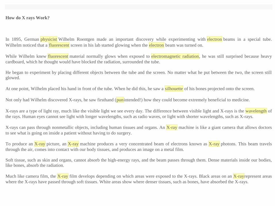
In 1895, German physicist Wilhelm Roentgen made an important discovery while experimenting with electron beams in a special tube.
Wilhelm noticed that a fluorescent screen in his lab started glowing when the electron beam was turned on.
While Wilhelm knew fluorescent material normally glows when exposed to electromagnetic radiation, he was still surprised because heavy
cardboard, which he thought would have blocked the radiation, surrounded the tube.
He began to experiment by placing different objects between the tube and the screen. No matter what he put between the two, the screen still
glowed.
At one point, Wilhelm placed his hand in front of the tube. When he did this, he saw a silhouette of his bones projected onto the screen.
Not only had Wilhelm discovered X-rays, he saw firsthand (punintended!) how they could become extremely beneficial to medicine.
X-rays are a type of light ray, much like the visible light we see every day. The difference between visible light and X-rays is the wavelength of
the rays. Human eyes cannot see light with longer wavelengths, such as radio waves, or light with shorter wavelengths, such as X-rays.
X-rays can pass through nonmetallic objects, including human tissues and organs. An X-ray machine is like a giant camera that allows doctors
to see what is going on inside a patient without having to do surgery.
To produce an X-ray picture, an X-ray machine produces a very concentrated beam of electrons known as X-ray photons. This beam travels
through the air, comes into contact with our body tissues, and produces an image on a metal film.
Soft tissue, such as skin and organs, cannot absorb the high-energy rays, and the beam passes through them. Dense materials inside our bodies,
like bones, absorb the radiation.
Much like camera film, the X-ray film develops depending on which areas were exposed to the X-rays. Black areas on an X-rayrepresent areas
where the X-rays have passed through soft tissues. White areas show where denser tissues, such as bones, have absorbed the X-rays.

A field-effect transistor (FET) is a type of transistor commonly used for weak-signal amplification (for example, for
amplifying wireless signals).The device can amplify analog or digital signals. It can also switch DC or function as an oscillator. In the FET,
current flows along a semiconductor path called the channel. At one end of the channel, there is an electrode called the source. At the other end
of the channel, there is an electrode called the drain. The physical diameter of the channel is fixed, but its effective electrical diameter can be
varied by the application of a voltage to a control electrode called the gate.The conductivity of the FET depends, at any given instant in time, on
the electrical diameter of the channel. A small change in gate voltage can cause a large variation in the current from the source to the drain. This
is how the FET amplifies signals.
Field-effect transistors exist in two major classifications. These are known as the junction FET (JFET) and the metal-oxide- semiconductor FET
(MOSFET).
The junction FET has a channel consisting of N-type semiconductor (N-channel) or P-type semiconductor (P-channel) material; the gate is made
of the opposite semiconductor type. In P-type material, electric charges are carried mainly in the form of electron deficiencies called holes. In
N-type material, the charge carriers are primarily electrons.In a JFET, the junction is the boundary between the channel and the gate. Normally,
this P-N junction is reverse-biased (a DC voltage is applied to it) so that no current flows between the channel and the gate. However, under
some conditions there is a small current through the junction during part of the input signal cycle.
In the MOSFET, the channel can be either N-type or P-type semiconductor. The gate electrode is a piece of metal whose surface is oxidized.
The oxide layer electrically insulates the gate from the channel. For this reason, the MOSFET was originally called the insulated-gate FET
(IGFET), but this term is now rarely used. Because the oxide layer acts as a dielectric, there is essentially never any current between the gate and
the channel during any part of the signal cycle. This gives the MOSFET an extremely large input impedance. Because the oxide layer is
extremely thin, the MOSFET is susceptible to destruction by electrostatic charges.Special precautions are necessary when handling or
transporting MOS devices.
The FET has some advantages and some disadvantages relative to the bipolar transistor. Field-effect transistors are preferred for weak-signal
work, for example in wireless communications and broadcast receivers. They are also preferred in circuits and systems requiring high
impedance.The FET is not, in general, used for high-power amplification, such as is required in large wireless communications and broadcast
transmitters.
Field-effect transistors are fabricated onto silicon integrated circuit (IC) chips. A single IC can contain many thousands of FETs, along with
other components such as resistors, capacitors, and diodes
Thermal biosensors or enzyme thermistors that have been predominantly studied in the author’s laboratory. The first work appeared as early as
1974 and has also been protected under patent in many countries. In principle, the device can be looked upon as a small microcalorimeter with
the biological components, usually as immobilized enzymes, placed in a small column in proximity to the heat sensing transducer, normally a
thermistor. In subsequent work the device was given a split-flow configuration to compensate for any non-specific heat by employing a
reference column lacking the active enzyme. The unit is now commercially available. A number of different devices have been developed over
the years including a unit comprising four channels, allowing four different substrates to be detected simultaneously. More recently, a major
breakthrough has been made towards a five-fold miniaturization, allowing sample volumes down to 5~1.
The major areas of application have been, and still are, in clinical chemistry, fermentation and process control. Some work has also been carried
out in environmental control using these devices as a toxi-guard. Potentially useful for the latter aspect is the use of living cells in the ‘microbe
thermistor’ configuration .With which the entire metabolic heat of an organism can be followed under the influence of potentially toxic elements
in the surrounding medium. For the latter aspect, however, individual enzymes have also been used for monitoring the enzymic heat production
as influenced by toxic compounds such as cyanide or heavy metals.
The major areas of application have been, and still are, in clinical chemistry, fermentation and process control (in this context I refer to the work
by Satoh et al. reported in this volume on the assay of creatinine and L-lysine, respectively); some work has also been carried out in
environmental control using these devices as a toxi-guard. Potentially useful for the latter aspect is the use of living cells in the ‘microbe
thermistor’ configuration with which the entire metabolic heat of an organism can be followed under the influence of potentially toxic elements
in the surrounding medium. For the latter aspect, however, individual enzymes have also been used for monitoring the enzymic heat production
as influenced by toxic compounds such as cyanide or heavy metals

microelectromechanical systems (MEMS) differential thermal biosensor integrated with microfluidics for metabolite measurements in either
flow-injection or flow-through mode. The MEMS device consists of two identical freestanding polymer diaphragms, resistive heaters, and a
thermopile between the diaphragms. Integrated with polymer-based microfluidic measurement chambers, the device allows sensitive
measurement of small volumes of liquid samples. Enzymes specific to a metabolic analyte system are immobilized on microbeads packed in the
chambers. When a sample solution containing the analyte is introduced to the device, the heat released from the enzymatic reactions of the
analyte is detected by the thermopile. The device has been tested with glucose solutions at physiologically relevant concentrations. In flow-
injection mode, the device demonstrates a sensitivity of approximately 2.1 muV/mM and a resolution of about 0.025 mM. In flow-through mode
with a perfusion flow rate of 0.5 mL/h, the sensitivity and resolution of the device are determined to be approximately 0.24 muV/mM and 0.4
mM, respectively. These results illustrate that the device, when integrated with subcutaneous sampling methods, can potentially allow for
continuous monitoring of glucose and other metabolites.
Optical Biosensor
sensor devices that use optical principles for the transduction of a biochemical interaction into a suitable output
signal for the detection of biological and chemical species.
Optical biosensor is one of such nano-biomolecular devices that have a potential to make a new dimension of research and device fabrication in
the field of optical and biomedical fields. Optical biosensors are powerful alternative to conventional analytical techniques, for their particularly
high specification, sensitivity, small size, and cost effectiveness. The research and technological development of optical biosensors have
experienced an exponential growth during the last decade because this technology has a great potential for the direct, real-time and label-free
detection of many chemical and biological substances.
3. Working:
A biosensor in general utilizes a biological recognition element that senses the presence of an analyte (the specie to be detected) and creates a
physical or chemical response that is converted by a transducer to a signal.
Applications
The sampling unit introduces an analyte into the detector. The recognition element binds or reacts with a specific analyte, providing biodetection
specificity. Enzymes, antibodies, receptors, DNA or even cells such as yeast or bacteria have been used as biorecognition elements

GLUCOSE BIOSENSOR
Pinnacle offers a GLUCOSE BIOSENSOR that is capable of providing real-time changes in glucose concentration in the brains of rodents. The
glucose biosensor has outstanding performance characteristics and rejects all common electroactive interferents, including ascorbate. It has a
linear range of at least 4 mM. We have successfully demonstrated that the glucose biosensor works in vivo and can provide continuous
monitoring of brain glucose concentration changes for 96+ hours. This biosensor is warrantied for 21 days from time of shipment.
Enzyme technology
Optical biosensor
There are two main areas of development in optical biosensors. These involve determining changes in light absorption between the reactants and
products of a reaction, or measuring the light output by a luminescent process. The former usually involve the widely established, if rather low
technology, use of colorimetric test strips. These are disposable single-use cellulose pads impregnated with enzyme and reagents. The most
common use of this technology is for whole-blood monitoring in diabetes control. In this case, the strips include glucose oxidase, horseradish
peroxidase and a chromogen (e.g. o-toluidine or 3,3',5,5'-tetramethylbenzidine). The hydrogen peroxide, was produced by the aerobic oxidation
of glucose, oxidising the weakly coloured chromogen to a highly coloured dye.
peroxidase
chromogen(2H) + H2O2 dye + 2H2O
The evaluation of the dyed strips is best achieved by the use of portable reflectance meters, although direct visual comparison with a coloured
chart is often used. A wide variety of test strips involving other enzymes are commercially available at the present time.A most promising
biosensor involving luminescence uses firefly luciferase (Photinus-luciferin 4-monooxygenase (ATP-hydrolysing), To detect the presence of
bacteria in food or clinical samples. Bacteria are specifically lysed and the ATP released (roughly proportional to the number of bacteria present)
reacted with D-luciferin and oxygen in a reaction which produces yellow light in high quantum yield.
luciferase
ATP + D-luciferin + O2 oxyluciferin + AMP + pyrophosphate + CO2 + light (562 nm)

The light produced may be detected photometrically by use of high-voltage, and expensive, photomultiplier tubes or low-voltage cheap
photodiode systems. The sensitivity of the photomultiplier-containing systems is, at present, somewhat greater (< 104 cells ml-1, < 10-12 M ATP)
than the simpler photon detectors which use photodiodes. Firefly luciferase is a very expensive enzyme, only obtainable from the tails of wild
fireflies. Use of immobilised luciferase greatly reduces the cost of these analyses.
Within the scope of biomedical signals and sensors, a biosignal can be defined as a description of a physiological phenomenon, irrespective of
the nature of this description. Since there is a nearly unlimited number of physiological mechanismsof interest, the number of possible biosignals
is very large
What are biosignals?
All types of biomedical systems either generate the signals to influence the human body, or analyze biosignals to extract useful information
about functioning of human body.
Signal – is the parameter that is observable from the object.
Biosignal is a description of physiological phenomenon of any nature.
Bio+Signal = “living object” + “function that carries information about the behavior or state”. Biosignals are the key objects in Biosystems.
Biosignal carries all information about the living object. We analyze signals which are coming from the body (ECG, EEG etc.) or are connected
to the body (Xray images, ultrasonic images). Biosignal can be used to understand the underlying physiological mechanisms of a specific
biological event or system.
2 Historical Aspects
The registration of human biosignals underwent a long-lasting development over many centuries. It began with visual inspections without the
use of any instruments, moved to the application of technical tools for signal registration, and is now in an implementation stage of pervasive,
almost imperceptible, monitoring. Obviously this development has been driven by patient and physician needs as well as by problems that were
encountered, interestingly not always relevant from a pure diagnostic point of view. As was recognized centuries ago concerning biosignal

analysis in Mahomed (1872): “. . . surely it must be to our advantage to appreciate fully all it tells us, and to draw from it all that it is capable of
imparting. . . .”
Classification of biosignals –
1 According to the physical nature of biosignals- Electric –Magnetic - Chemical- Mechanical (acoustic) - Optical - Thermal
Classification of biosignals
- 2 According to the system of origin of biosignals
- Endocrine system - Nervous system (Central and Peripheral) - Cardiovascular system - Vision system - Auditory system - Musculoskeletal
system - Respiratory system - Gastrointestinal System - Blood system
Classification according to the physical nature of signal
Electric signals
Electric field is generated in cells (nerve and muscle) and organs because of intra- and extracellular ionic currents. They are the results of
electrochemical processes in the single ionic channels.
Types of electrical signals
Neural cells
ENG – electroneurogram , EEG – electroencephalogram , ERG – electroretinogram
Muscle cells , ECG – electrocardiogram ,EMG – electromyogram
Other cells EOG,– electrooculorgam GSR – galvanic skin response
Magnetoencephalography (MEG) MEG is based on measuring the magnetic field outside the head using an array of very sensitive magnetic
field detectors (magnetometers).
The signals recorded by EEG and MEG directly reflect current flows generated by neurons within the brain. The temporal frequency content of
these signals ranges from less than 1 Hz (one cycle per second) to over 100 Hz (100 cycles per second). Because MEG and EEG measure
neuronal activity in “real time” the connections activated either at rest or during task can be measured, giving us a picture of the dynamic
interactions among brain networks. MEG has much greater temporal resolution than fMRI so MEG-based analysis provides high temporal
resolution data for analyzing the neuromagnetic correlates of fMRI connectivity, its timefrequency content, and temporal interactions.
Magnetocardiography (MCG)
MCG is the measurement of magnetic fields emitted by the human heart from small currents by electrically active cells of the heart muscle.
Chemical biosignals Signals providing information about concentration of various chemical agents in the body
- Level of glucose (diabetes)
- Blood oxygen level (asthma,
obstructive pulmonary disease, heart and kidney failure)
- Gases in blood and breathing airflow (anesthetic gases, carbon dioxide etc.) - pH
Mechanical biosignals Biomechanical signals reflect mechanical functions of body parts Examples:
- Blood Pressure
- Accelerometer signals describing human movements, gait, balance and pose (Parkinson disease, mobile applications, fitness)
- Chest movements during respiration - Air flow characteristics during MLV
Acoustic biosignals
Subset of mechanical signals that describe the acoustic sound produced by the body (vibrations and motions).
Bio acoustic signals give access to diverse body sounds:
- Cardiac sounds (phonocardiography)
- Snoring (Obstructive Sleep Apnea detction)
- Swallowing

- Respiratory sounds
- Crackles of joints and
muscles Often measured at the skin using acoustic transducers such as microphones and accelerometers
Phonocardiogram (PCG) PCG reflects sounds of heartbeats,
produced by heart sounds corresponding to two consecutive heart valve closures.
Indicates closure strength and the valve’s stiffness.
Respiratory sounds Reflect
normal breathing sounds superimposed with crackles, cough sounds,
Thermal biosignals Body temperature in the point and temperature maps, may describe heat loss and heat absorption in the body, or temperature
distribution over the body surface
Classification according to the system of origin of signal
Endocrine System Is the collection of glands of an organism that secrete hormones directly into the circulatory system to be carried toward a
distant target organ. Signals: - Chemical – Optical
Signals from Nervous System
Neurons and spinal cord
- 1 )Electroneurogram (Spike trains)
- 2 )Magnetoneurogram
Brain, - 1 )EEG, 2) MEG - Event-Related Potentials (acoustic, visual)
- Neurovisualization 1 (MRI/fMRI, CT, PET, SPECT)

Cardiovascular System
Heart & blood vessels - ECG - MCG (Current Density Maps) - Blood pressure
- Heart Rate Variability Visualization - Ultrasonic Imaging - MRI, Ultrasonic, X-ray
Vision system
- EEG (visual cortex) - VEP (Visual Evoked Potentials) - EOG (Electrooculogram) - ERG (Electroretinogram)
Electroretinography
Electroretinography measures the electrical responses of various cell types in the retina, including the photoreceptors (rods and cones), inner
retinal cells (bipolar and amacrine cells), and the ganglion cells
Auditory system - EEG (Auditory Evoked Potentials) – Audiometry
Respiratory system
- Chemical signals (gas concentration)- Mechanical (airflow, pressure, volume)
- Spirometry (flow-volume) - Plethysmography (volume)
Gastrointestinal System
- MRI - X-ray - Ultrasound Imaging - Chemical signals- Electrogastrogram
Amperometric biosensor
The choice of the biological recognition element is the crucial decision that is taken when developing a novel biosensor design.
It is important to define criteria for, for example, a suitable redox enzyme for a specifi c biosensor.
Most importantly, the enzyme needs to selectively react with the analyte of interest. The redox potential of the primary redox center needs to be
within a suitable potential window (usually between − 0.6 and 0.9 V vs. Ag/AgCl).
The enzyme needs to be stable under the operation and storage conditions of the biosensor and should provide a reasonable long - term stability.

. An important factor, especially with respect to potential commercialization, is that the redox enzyme is available at reasonable costs and effort.
The advantages of employing enzymes in biosensor architectures are the following:
i) They exhibit a very high catalytic activity with a turnover on a per mole basis which makes them not only exceptional
bioelectrocatalysts for effective signal amplifi cation in biosensors but also for biofuel cells. Good turnover frequencies kcat are in
the range of up to at least 100 s
ii) − 1 . ii) Typically, enzymes have a high selectivity for their substrates. iii) In addition, the driving force, the redox potential that is
needed to achieve enzymatic biocatalysis, is often very close to that of the substrate of the enzyme. Therefore, biosensors can
operate at moderate potentials. Figure 1.2 Examples
iii) for biosensor components. 6 1 Amperometric Biosensors iv)
iv)
v) In several cases, an improvement of the enzyme stability was found when enzymes were immobilized on transducer surfaces.
The disadvantages of using enzymes in bioelectrochemical devices are the following:
i) Enzymes are rather large molecules. Thus, despite the high catalytic turnover at the active site of the enzyme, the overall catalytic
(volume) density is low.
ii) As an example, at most about a few picomoles of enzyme molecules per square centimeter are contained in a monolayer of
enzymes. Barton and coworkers calculated that the theoretical current density in such a monolayer is about 80 μ A cm − 2 under
the assumption that the “ footprint ” of the enzyme is about 100 nm 2 and the turnover frequency is about 500 s − 1.
iii) ii) Often the active site of the enzyme is deeply buried within the surrounding protein shell. Thus, direct ET is often not possible
and artifi cial redox mediators are required. iii) Enzymes have a limited lifetime and, therefore, biosensors exhibit only a limited
long - term stability. So far, operational lifetimes of biosensors have been realized to up to 30 to 60 days.
“ First - Generation ” Biosensors Though many highly complex detection schemes can be found in biosensor designs, the simplest
approach to a biosensor is the direct detection of either the increase of an enzymatically generated product or the decrease of a substrate of
the redox enzyme.
Additionally, a natural redox mediator that is participating in the enzymatic reaction can be monitored. In all three cases it is necessary
that the compound monitored is electrochemically active.
The use of GOx as biological recognition element for a “first - generation” biosensor design is the typical case and has been employed
numerous times.
Here, the increasing concentration of the product H2O2 or the decrease in O2 concentration as natural co-substrate can be
electrochemically detected in order to monitor glucose concentration.
The major drawbacks of the first - generation biosensor approach are the following:
(i) if the O2 concentration is monitored, it is challenging to maintain a reasonable reproducibility due to varying O2 concentrations
within the sample and
( ii) working electrode potentials for either the oxidation of H2O2 or the reduction of O2 are not optimal because these potentials are
prone to the impact of interferences present in
Second lesson
Biological samples, such as ascorbic acid or dopamine. “ Second - Generation ” Biosensors In order to achieve biosensors which
operate at moderate redox potentials the use of artifi cial redox mediators was introduced for the “ second - generation ” biosensors.
The employed redox enzyme for the analyte of interest is able to donate or accept electrons to or from an electrochemically active
redox mediator.
It is important that the redox potential of this mediator is in tune with the cofactor(s) of the enzyme.
Preferably, the redox mediator is highly specifi c for the selected ET pathway between the biological recognition element and the
electrode surface.
Note that the difference in potential between the different cofactors and the introduced artifi cial redox mediator should not be less than
ΔE ∼ 50 mV
What are the most important properties of redox mediators suitable for biosensors?
First of all, the electrochemistry has to be reversible and they need to be stable in the oxidized and reduced forms.
No side reactions should occur.

The redox potential needs to be compatible with the enzymatic reaction. It is helpful if the basic structure of the redox mediator also
allows for chemical modifi cation.
The major drawback of using either a natural or an artifi cial free - diffusing redox mediator in a biosensor
is that suffi cient natural (e.g., O2 ) or artifi cial mediator needs to be available to the active site of the enzyme and, subsequently, at
the electrode surface for generating a detectable current signal.
In addition, and of more importance to the accuracy and long - term stability as well as product safety,
Artifi cial mediator molecules that are not securely fi xed within the sensing fi lm can leak from the electrode surface. This will change
the sensor performance over time.
In addition, not all redox mediators are biocompatible. The described problems with the use of free - diffusing redox mediators are not critical
for single - use devices. For example, self - monitoring devices for monitoring blood glucose levels are very successfully used by diabetes
patients at home . Amperometric biosensors function by the production of a current when a potential is applied between two electrodes.
They generally have response times, dynamic ranges and sensitivities similar to the potentiometric biosensors. The simplest amperometric
biosensors in common usage involve the Clark oxygen electrode
This consists of a platinum cathode at which oxygen is reduced and a silver/silver chloride reference electrode.
When a potential of -0.6 V, relative to the Ag/AgCl electrode is applied to the platinum cathode, a current proportional to the oxygen
concentration is produced.
Normally both electrodes are bathed in a solution of saturated potassium chloride and separated from the bulk solution by an oxygen-permeable
plastic membrane (e.g. Teflon, polytetrafluoroethylene). The following reactions occur:
Ag anode 4Ag0 + 4Cl- 4AgCl + 4e-
Pt cathode O2 + 4H+ + 4e- 2H2O

Potentiometric biosensor
Potentiometric biosensors make use of ion-selective electrodes in order to transduce the biological reaction into an electrical signal. In the
simplest terms this consists of an immobilized enzyme membrane surrounding the probe from a pH-meter (where the catalyzed reaction
generates or absorbs hydrogen ions
There are three types of ion-selective electrodes which are of use in biosensors:
1. Glass electrodes for cations (e.g. normal pH electrodes) in which the sensing element is a very thin hydrated glass membrane which
generates a transverse electrical potential due to the concentration-dependent competition between the cations for specific binding sites.
The selectivity of this membrane is determined by the composition of the glass. The sensitivity to H+ is greater than that achievable for
NH4+,
2. Glass pH electrodes coated with a gas-permeable membrane selective for CO2, NH3 or H2S. The diffusion of the gas through this
membrane causes a change in pH of a sensing solution between the membrane and the electrode which is then determined.
3 Solid-state electrodes where the glass membrane is replaced by a thin membrane of a specific ion conductor made from a mixture of silver
sulphide and a silver halide. The iodide electrode is useful for the determination of I- in the peroxidase reaction
The reaction occurring next to the thin sensing glass membrane causes a change in pH which may be read directly from the pH-meter's display.
Typical of the use of such electrodes is that the electrical potential is determined at very high impedance allowing effectively zero current flow
and causing no interference with the reaction.
Potentiometric assays rely on recording the potential/pH variation, and these determinations are applicable in food, clinical or environmental
analysis. The analytical signal is due to the concentration variation of an ionic species. Potentiometric measurements are applied to the
determination of many organic and inorganic species (sugars, urea, antibiotics, neurotransmitters, pesticides, but also ammonia, carbon dioxide
and many ionic species). Potentiometric biosensors are developed by combining a biorecognition element (essentially an enzyme) with a
transducer that senses the variation in protons (or other ions) amount, the recorded analytical signal being logarithmically correlated with the

analyte concentration. Potentiometric measurements are applied to the determination of many organic and inorganic species (sugars,
urea, antibiotics, neurotransmitters, pesticides, but also ammonia, carbon dioxide and many ionic species).
Potentiometric biosensors are developed by combining a biorecognition element (essentially an enzyme) with a transducer that senses the
variation in protons (or other ions) amount, the recorded analytical signal being logarithmically correlated with the analyte concentration.
The present Editorial deals with the presentation of several types of sensors based on different transducers and biorecognition elements.
The simplest transducer in the development of potentiometric biosensors is the glass pH electrode. Glucose oxidase immobilization was
achieved using cellophane, nylon or nitrocellulose, membranes that are subsequently fixed on the sensitive bulb of the pH electrode that senses
the pH diminution, as a result of the biocatalytical reaction occurring in the enzyme layer (glucose oxidation by glucose oxidase). Such
potentiometric enzyme sensors possess a linear range of 10-4 to 5 × 10⁻² M, allowing for glucose assay in fruit juices.
Glucose oxidase has been also coupled with other signal transducers for potentiometric purposes: the enzyme has been entrapped in a
polypyrrole film by electro-polymerization on a Pt electrode, resulting in a potentiometric glucose biosensor.
Ion selective electrodes other than the pH glass electrode, such as the fluoride electrode, were also used in the development of potentiometric
sensors. Glucose, maltose or lactate can be determined relying on the reaction of 4-fluoroaniline with H2O2 generated by the corresponding
substrate oxidases. The fluoride anions resulted from the peroxidase-catalyzed reaction of fluoroaniline with hydrogen peroxide that involves
cleavage of the C-F bond, are potentiometrically detected with the specific fluoride electrode. The analytical signal represented by the recorded
voltage difference depends linearily on the logarithm of the analyte concentration within the range 0.1–1 mM.
Amygdalin can be assessed with a potentiometric biosensor using as transducer a cyanide anion selective electrode.
Enzymes such as glucose oxidase, lipase or acetylcholinesterase, were also immobilized on the sensitive membranes of ion-selective field
effect transistors, resulting in the determination of glucose, triglycerides and pesticides respectively.
The development of potentiometric biosensors can also involve gassensitive electrodes (such as for carbon dioxide and ammonia resulted from
enzyme reactions), as in the case of urea determination. Gas–sensitive electrodes as transducers are obtained on the basis of a pH glass electrode
and an electrolyte layer that is maintained close to the sensitive bulb by a gas-permeable membrane.
Increasingly complex electrode modification resulted in excellent analytical parameters:
Hypoxanthine assessment in fish meat was performed using a potentiometric enzyme electrode relying on xanthine oxidase and ferrocene
carboxylic acid entrapment in a polypyrrole film that was obtained by applying galvanostatic technique. The linear range of analytical response
of the developed enzyme sensor was 5–20 μM.
The immobilization of acetylcholinesterase on an antimony disk electrode by intermolecular cross-linkage of the enzyme and
bovine serum albumin, using glutaraldehyde vapor, resulted in a potentiometric sensor enabling the assay of trichlorfon with fast response,
given the ability of the organophosphorous pesticide to inhibit AChE.
A solid-state electrode consisting in a conducting resin (graphite/ epoxy) and polyvinyl chloride matrix and responding to ammonium ions was
used as transducer in urea assay.
Another type of urea biosensor consists of a glass-sealed metal microelectrode coated with a polyethylenimine film. Physical adsorption and
subsequent reticulation with diluted aqueous glutaraldehyde solution for urease immobilization, resulted in enhanced analytical performances
meaning short response times (15– 30 s), a dynamic range with sigmoidal response versus urea for a concentration range 1×10−2.5 to 1×10−1.5 M
and a lifetime of 4 weeks.
Urease immobilization on a modified fullerene nanomaterial and subsequent deposition on a screen-printed electrode that contained a poly (n-
butyl acrylate) membrane entrapped with a hydrogen ionophore, resulted in a novel biosensor. The linearity of the biosensor was comprised
between 2.31 × 10⁻³ M and 8.28 × 10⁻⁵ M. The sensitivity of the biosensor was very close to the theoretical Nernstian slope: 59.67 ± 0.91
mV/decade. Tests performed on cations commonly present in urine samples such as Na+, K+, Ca2+, Mg2+ and NH4+ showed that these ionic
species did not interfere with the urea analytical signal. The results obtained in real urine samples range between 17 and 19 mM, the difference
between the results of UV-Vis standard spectrometry and those obtained with the potentiometric biosensor being smaller than 5%.
The analytical parameters and methods’ validation confirm the viability of the developed potentiometric sensors, for the assessment of various
key biomolecules.
Potentiometric Biosensor
Characteristics of Potentiometric Sensor.
The potentiometric sensor (the base sensor) has the characteristic that are different from amperometric sensors. These are:
1. The measured species (such as H+, NH4+, etc.) is not consumed

.
2. The sensor measures the activity (for dilute solutions, molar concentration can be used), of a specific ion (Co) in reference to its internal
standard (Ci).
3. The output is in voltage (Em).
4. The ion specificity comes entirely from the membrane. For example, there is a membranes specific to H+, one for NH4+, one for Ca++, etc.
5. The output of the base sensor is in voltage; independent of the sensor size; and proportional to natural log of Co.
Configuration of Biosensor.
For potentiometric biosensors, the outer membrane is often not used.Often, the inner membrane is not used either. In such a case, the enzyme is
immobilized directly on the surface of the potentiometric sensor.
A large variety of potentiometric biosensors is developed using biocatalytic and bioaffinity-based biosensing schemes. However, only few of
them could be applied for the biomedical analysis.
The most promising are those for the detection of main products of protein metabolism, namely urea and creatinine. A novel group of
potentiometric biosensors is constituted by bioaffinity-based devices that could be used for immunoassays or genoanalysis.
Biosensors constitute a significant group of analytical tools important in several fields of modern analytical chemistry
Nearly all types of biointeractions could be implemented into analyte recognition schemes. In these schemes may participate small
biomolecules, enzymes, antibodies, nucleic acids as well as viruses, whole cells and microorganisms.
. Another flagship example of commercial biosensor development is a large market of glucose biosensing devices for diabetes. Important areas,
like environmental, food and pharmaceutical analysis.
Without doubt optical and amperometric biosensors exemplify the largest group of devices which find applications in real analysis.
Potentiometry, one of the oldest instrumental methods, has well-established position in the sensoric analysis

This analytical technique is an attractive tool for many practical applications as it allows the determination of various ions in the wide range of
concentrations and employs inexpensive measurement equipment.
Nearly all potentiometric sensors, including glass electrodes, metal oxide based sensors as well as ion-selective electrodes, are commercially
available
According to IUPAC recommendations
Potentiometric biosensors have two important features:
(i) Biological component is an integral part of the sensor receptor, recognizing an analyte,
(ii) The analytical signal generated by the biosensor is a potential.
Although the definition is well-known, the recollection of these two apparently obvious statements is necessary because well-presentable
“biosensor” term is often abused in the analytical literature. In fact, many papers title or content contain this term but actually are not devoted to
biosensors. Many of such articles report on sensors only cooperating with the separate biochemical/biological components (for example enzyme
column in FIA system with potentiometric electrode).
Urea biosensors Urea is the main end-product of protein metabolism and can be easily detected using potentiometric enzyme-based biosensors.
The non-protein nitrogen compound present in the highest levels in blood is urea as nearly 95% of protein nitrogen is metabolized to urea
nitrogen
The decreased levels of plasma urea are rarely observed and characteristic for patients with severe liver diseases or low protein intake.
As the final product of the metabolism, urea is an important factor that allows to appraise the renal function of kidneys.
Elevated blood urea nitrogen is called azoteria.
Very high blood urea levels caused by severe renal dysfunction is called uremic syndrome.
It is eventually fatal if not treated by dialysis or kidney transplantation. The physiological level of urea in blood is between 2.5 and 8.6 mM
depending on the diet. It increases significantly during chronic and sharp kidney failure (50–70 and 120–150 mM, respectively).

Products of the hydrolysis shown in Scheme 1 clearly define the kind of internal sensors applicable for the biosensors development.
Several potentiometric sensors including gas electrodes, ion-selective electrodes as well as numerous pH-sensors are especially useful for such
biomodifications.
The number of potentiometric urea biosensors reported in the analytical literature is quite large because urease is an inexpensive and stable
biocatalyst easily available in various forms of highly purified and active enzyme preparates.
Therefore, urease is a model biocatalyst often applied for the investigation of novel enzyme immobilization protocols, the demonstration of
potential utilities of newly developed sensors, the development of novel biosensing schemes, etc. However, the resulting biosensors are not
dedicated for any particular kind of analysis.
Some urea biosensors have been developed as disposable devices for the indirect inhibitive detection of heavy metal ions
Creatinine is produced in the body by dephosphorylation of phosphocreatine as well as by dehydration of creatine. Creatine is synthesized in
liver from arginine, methionine and glicyne and converted into phosphocreatine, which serves as high-energy source for muscles.
Creatinine is one of the most significant analytes in the modern clinical analysis
. Determination of this metabolite in various physiological fluids is useful for the evaluation of renal, muscular and thyroid dysfunctions.
Such analyses are helpful for the biomedical diagnosis of acute myocardial infarction as well as for the quantitative description of hemodialysis
treatment.
Creatinine is a marker for muscle mass and its generation reflects slow turnover of muscle protein
Whereas the potentiometric transduction for the urea biosensing is evident, in case of the creatinine biosensing both amperometric and
potentiometric schemes of detection could be proposed.
The development of creatinine biosensors has followed two paths based on trienzyme or monoenzyme conversion of the target analyte.
Three enzyme-based systems catalyzing the sequential conversion of creatinine to creatine (hydrolysis), creatine to sarcosine (hydrolysis) and
finally oxidation of sarcosine to glycine, are predominantly implemented in amperometric creatinine biosensors.

The source of the analytical signal in such devices is the detection of electroactive coreagents of the final enzyme reaction: consumed oxygen or
produced hydrogen peroxide. Unfortunately, such devices are disturbed by interferences from intermediate species (especially creatine) as well
as from other redox species and therefore subtractive measurement modes are recommended for such analyses
Biosensors can be classified into different groups depending on the method of signal transduction: optical, electrochemical, thermometric,
piezoelectric or magnetic. Optical biosensors are the most commonly reported class of biosensors. Optical detection is performed by exploiting
the interaction of the optical field with a biorecognition element. Optical biosensing can be broadly divided into two general modes: label-free
and label-based. Briefly, in a label-free mode, the detected signal is generated directly by the interaction of the analysed material with the
transducer. In contrast, label-based sensing involves the use of a label and the optical signal is then generated by a colorimetric, fluorescent or
luminescent method. Simple molecules such as glucose can be detected by enzymatic oxidation using label-assisted sensing. The glucose
analysis of blood is the most commercially successful (so far) application of a biosensor, i.e. the handheld glucose meter used by diabetics.
However, in some situations, e.g. antibody–antigen interaction where a label is conjugated with one of the bioreactants, labelling can alter the
binding properties and therefore introduce systematic error to the biosensor analysis.
An optical biosensor is a compact analytical device containing a biorecognition sensing element integrated with an optical transducer system
.The basic objective of an optical biosensor is to produce a signal which is proportionate to the concentration of a measured substance (analyte).
The opticalbiosensor can use various biological materials, including enzymes, antibodies, antigens, receptors, nucleic acids, whole cells and
tissues as biorecognition elements. Surface plasmon resonance (SPR), evanescent wave fluorescence and optical waveguide interferometry
utilize the evanescent field in close proximity to the biosensor surface to detect the interaction of the biorecognition element with the analyte.
There are a huge number of variations in the construction of optical biosensors and this review will focus on a few that have been selected on the
basis of their widespread application and tending towards the detection of the most biologically relevant substances.
Surface plasmon resonance biosensors
The physical phenomenon of SPR was first observed in 1902. This observation of an esoteric optical phenomenon evolved through decades into
a full understanding of surface plasmon physics and in 1983 SPR was first successfully used to construct an SPR-based sensor to detect
biomolecular interactions. The first commercial SPR-based biosensor instrument was launched by Pharmacia Biosensor AB, which was later
renamed Biacore. SPR instruments are currently produced by multiple manufacturers and the SPR-based biosensor is currently the predominant
optical biosensing method.
The SPR phenomenon occurs on the surface of metal (or other conducting materials) at the interface of two media (usually glass and liquid)
when it is illuminated by polarized light at a specific angle. This generates surface plasmons and consequently a reduction of the intensity of

reflected light at a specific angle known as the resonance angle. This effect is proportionate to the mass on the surface. A sensorgram can be
obtained by measuring the shift of reflectivity, angle or wavelengths against time. In all configurations, the SPR phenomenon enables direct,
label-free and real-time changes of refractive index at the sensor surface, which is proportionate to the biomolecule concentration. To measure a
ligand–analyte interaction, one interacting molecule must be immobilized on the sensor surface. A practical SPR instrument combines an optical
detector part, usually measuring intensity shift, a sensor chip with a gold surface and a layer enabling ligand immobilization, which is integrated
with a fluidics system enabling a flow-through operation. The SPR chip contains a functional layer which enables the immobilization of
interacting molecules. Current instrumentation is dominated by immobilization based on a self-assembled monolayer covered with a
carboxymethylated dextran. This configuration enables the effective immobilization of protein using N-hydroxysuccinimide (NHS) chemistry.
In a practical experiment one interaction component, e.g. the ligand, is permanently attached to the chip surface and another interacting
component, e.g. the analyte, flows over the surface and binds to the ligand. A typical SPR experiment is documented. The ligand (A) is
immobilized on the surface and interacts with the analyte (B). Experimental traces of response against time are then fitted and a practical result
of SPR analysis are then kinetic constants kon, koff and equilibrium constants Ka=kon/koff and Kd=1/Ka.
The detection of surface binding by SPR is a widely used concept. However, in practical life there are multiple other effects that can occur and
complicate SPR analysis, which include non-1:1 binding stoichiometry, avidity, non-specific absorption of ligand and mass transfer limitation
Dealing with those is well described in specialized monographs.
For practical applications there are three types of SPR analyses: kinetic analysis, equilibrium analysis and concentration
analysis. Kinetic and equilibrium analyses are commonly used to characterize any molecular interaction: ligand–analyte binding, antibody–
antigen interaction, receptor characterization etc. No comparable technology is available to characterize biomolecular interaction in real time
without labelling and therefore SPR is currently a prime tool for discovery research in biological sciences and pharmaceutical drug development.
The SPR technique also has multiple applications in the concentrationanalysis of any analyte if a ligand specific to it is available and can be
immobilized on the SPR chip. The concentration is then obtained by measuring direct binding or alternatively from the rate of binding in a mass
transport limited mode. Concentration analysis has wide application in multiple fields: clinical diagnostics, environmental analysis, food etc. An
SPR biosensor assay was used for the diagnosis of different stages of Epstein–Barr virus infection in clinical serum samples by the simultaneous
detection of the antibodies against three different antigens present in the virus. A soluble vascular endothelial growth factor receptor was
determined using an SPR chip with an immobilized ligand and a detection limit of 25 μg · l−1 was achieved. Rapid screening methods employing
SPR portable biosensors have great potential in food monitoring. The sensitive on-site analysis of antibiotics in milk samples was realized by a
portable six-channel SPR biosensor and the mycotoxin patulin was detected by an immuno-chemical SPR biosensor with a detection limit of
0.1 nM. An SPR biosensor was also used for the sensitive and anion-selective detection of As(III) with a limit of detection of 1.0 nM.

SPR imaging
SPR imaging (SPRi) takes the SPR analysis a step further by merging the sensitivity of SPR and spatial imaging in a microarray format allowing
the simultaneous study of multiple different interactions. SPRi allows simultaneously studying multiple different interactions on an array of
precisely patterned molecules. High throughput, sensitivity and obtaining the spatially resolved images of biointeractions open up a great future
for SPRi to be applied in clinical chemistry and medicine for the screening of biomarkers and therapeutic targets. For example, a succesful
application of this method was the kinetic study of the binding between an immunosuppressive drug (FK506) and its target protein (FK506-
binding protein 12 (FKBP12)) in a high-throughput SPRi format with a detection limit of 0.5 nM.
Evanescent wave fluorescence biosensors
In these biosensors, the biological recognition and the consequent binding event occur within the confines of an evanescent wave. The
evanescent wave arises from the manner in which light behaves when confined in an optical waveguide or fibres. Guided light is totally
internally reflected when it meets the interface of the waveguide/fibre and a surrounding medium with a lower index of refraction, as a result an
electromagnetic field called an evanescent wave extends out from the interface into the lower index medium. The evanescent wave decays
exponentially with distance from the surface, generally over the distance of 100 nm to approximately a wavelength. Since the evanescent wave
is such a near-surface phenomena, detection employing evanescent wave excitation to generate the fluorescent signal is surface-sensitive,
meaning that only fluorescent molecules near the surface are excited. This geometric limitation can help to minimize unwanted background
signal from a bulk sample while only enhancing the signal from fluorophores captured on the surface. A profuse variety of biosensors was
developed based on this principle with a wide array of applications ranging from clinical diagnostics to biodefence to food testing. Moreover,
with the recent commercialization of a number of waveguide-based sensors it is anticipated that these sensors will make a major impact on
healthcare-related fields. The performance of this platform was assessed using >200 clinical samples from subjects comprising healthy
individuals and those positive for HIV, syphilis and hepatitis C, and excellent specificity was demonstrated. The evanescent wave aptamer-based
fluorescence biosensor was used for the rapid, sensitive and highly selective detection of 17β-oestradiol, an endocrine-disrupting compound
frequently detected in environmental water samples
Other optical biosensors
Optical waveguide interferometric biosensors
An integrated planar optical waveguide interferometric biosensor is a combination of evanescent field sensing and optical phase difference
measurement methods. By probing the near-surface region of a grating sensor area with the evanescent field, any change of the refractive index
of the probed volume induces a phase shift of the guided mode compared with a reference field, typically of a mode propagating through the
reference arm of the same waveguide structure. The interfering fields of these modes produce an interference signal detected at the sensor's
output, whose alteration is proportional to the refractive index change and the signal is related to the concentration of the analyte. This
technique, also called resonant waveguide grating (RWG), is suitable for detecting the redistribution of cellular contents, studying cellular
responses and cellular processes, and was also applied to the detection of the avian influenza virus .
Ellipsometric biosensors
An ellipsometric biosensor measures changes in the polarization of light when it is reflected from a surface. This platform was applied in
detecting the binding of influenza A virus strains with a panel of glycans of diverse structures. The apparent equilibrium dissociation constants
(avidity constants, 10–100 pM) were used as characterizing parameters of viral receptor profiles. Microarray biosensors based on total internal
reflection imaging ellipsometry for the detection of the serum tumour biomarker CA19-9 had an estimated detection limit of CA19-9 of
18.2 units · ml−1, which is lower than the cut-off value for a normal level.
Reflectometric interference spectroscopy biosensors
Reflectometric interference spectroscopy (RIfS) is a label-free and time-resolved method where the simple optical set-up is based on white light
interference at thin layers. Changes in the phase and amplitude of polarized light provides information about the thickness and refractive index
of the adsorbed protein layer. This method was used for the detection and quantification of diclofenac in bovine milk and the obtained limit of
detection was 0.112 μg · l−1 in the complex milk matrix. An RIfS biosensor for the detection of circulating tumour cells was capable of the
selective detection of cancer cells within a concentration range of 1000–100000 cells · ml−1 with a detection limit of <1000 cells · ml−1.
Surface-enhanced Raman scattering biosensors
Surface-enhanced Raman scattering (SERS) is a biosensing technique which enhances the intensity of the vibration spectra of a molecule by
several orders of magnitude when it is in close proximity to nano-roughened metallic surfaces or nanoparticles made of gold or silver. A SERS-
active surface fabricated on the tip of the optical fibres was applied to the sensitive detection of cancer proteins (∼100 pg) in a low sample
volume (∼10 nl). A SERS biosensor for the fast and sensitive detection of a protein biomarker of endocrine-disrupting compounds in an aquatic
environment,
Piezoelectric effect
Piezoelectric effect is not a completely novel idea since it has been known since the 19th
century with broad technological applications
since the beginning of the 20th
century. The discovery of piezoelectric effect is connected with the names of famous physicists Jacques Curie

and Pierre Curie who recognized that anisotropic crystals i.e. crystals without center of symmetry can generate electric dipole when
mechanically squeezed. The electric dipole is also called piezoelectricity. The described effect can work in oppose way when an anisotropic
crystal become deformed due to voltage imposed on it. The aforementioned phenomenon is depicted as figure 1. The mechanical deformation is,
however, a simple situation and oscillation is rather chosen in the common applications like here described analytical devices. In the case of
oscillation, an alternating voltage is imposed on the crystal and mechanical oscillation then occurs.
The oscillations can have many appearances depending upon material and other conditions like electrical contacts, shape of the crystals
etc. The oscillations occur in adiabatic waves which are typically spread over the mass like the acoustic one. In the oscillating crystals, the both
surfaceBiosensors are miniaturized devices composed from the sensor part known also as physico-chemical transducer and a part of biological
origin like antibody, enzyme, nucleic acid sequence, organelle, viable cell or slice of a tissue. We can entitle as the first biosensor the device
constructed by Clark and coworkers in early1960s. The inventors constructed a voltammetric analysator having enzyme glucoseoxidase tightly
connected with the surface of working electrode. Because the device had the both BIOlogical origin part and electrochemical SENSOR,
acronym biosensor has appeared afterwards.
Quartz crystal microbalance (QCM)
A quartz crystal microbalance (QCM) measures a mass variation per unit area by measuring the change in frequency of a quartz crystal resonator.
The resonance is disturbed by the addition or removal of a small mass due to oxide growth/decay or film deposition at the surface of the
acoustic resonator. The QCM can be used under vacuum, in gas phase ("gas sensor", first use described by King and more recently in
liquid environments. It is useful for monitoring the rate of deposition in thin film depositionsystems under vacuum. In liquid, it is highly
effective at determining the affinity of molecules (proteins, in particular) to surfaces functionalized with recognition sites. Larger entities
such as viruses or polymers are investigated, as well. QCM has also been used to investigate interactions between biomolecules.
Frequency measurements are easily made to high precision hence, it is easy to measure mass densities down to a level of below 1 μg/cm2.
In addition to measuring the frequency, the dissipation factor (equivalent to the resonance bandwidth) is often measured to help analysis.
The dissipation factor is the inverse quality factor of the resonance, Q−1 = w/fr (see below); it quantifies the damping in the system and is
related to the sample's viscoelastic properties The effect is explained by the displacement of ions in crystals that have a nonsymmetrical
unit cell
When the crystal is compressed, the ions in each unit cell are displaced, causing the electric polarization of the unit cell.
Because of the regularity of crystalline structure, these effects accumulate, causing the appearance of an electric potential difference between certain
faces of the crystal.
When an external electric field is applied to the crystal, the ions in each unit cell are displaced by electrostatic forces, resulting in the mechanical
deformation of the whole crystal.
Piezoelectricty
Piezoelectricity, also called the piezoelectric effect, is the ability of certain materials to generate an AC (alternating
current) voltage when subjected to mechanical stress or vibration, or to vibrate when subjected to an AC voltage, or both. The most
common piezoelectric material is quartz. Certain ceramics, Rochelle salts, and various other solids also exhibit this effect.
A piezoelectric transducer comprises a "crystal" sandwiched between two metal plates. When a sound wave strikes one or both of the plates,
the plates vibrate. The crystal picks up this vibration, which it translates into a weak AC voltage. Therefore, an AC voltage arises between the
two metal plates, with a waveform similar to that of the sound waves. Conversely, if an AC signal is applied to the plates, it causes the crystal
to vibrate in sync with the signal voltage. As a result, the metal plates vibrate also, producing an acoustic disturbance.
Piezoelectric transducers are common in ultrasonic applications, such as intrusion detectors and alarms. Piezoelectric devices are employed
at AF (audio frequencies) as pickups, microphones, earphones, beepers, and buzzers. In wireless applications, piezoelectricity makes it
possible to use crystals and ceramics as oscillators that generate predictable and stable signals at RF (radio frequencies).
Pressure Sensor
A pressure sensor is a device for pressure measurement of gases or liquids. Pressure is an expression of the force required to stop a fluid from
expanding, and is usually stated in terms of force per unit area. A pressure sensor usually acts as a transducer; it generates a signal as
a function of the pressure imposed. For the purposes of this article, such a signal is electrical.

Pressure sensors are used for control and monitoring in thousands of everyday applications. Pressure sensors can also be used to indirectly
measure other variables such as fluid/gas flow, speed, water level, and altitude. Pressure sensors can alternatively be called pressure
transducers, pressure transmitters, pressure senders, pressure indicators, piezometers and manometers, among other names.
Pressure sensors can vary drastically in technology, design, performance, application suitability and cost. A conservative estimate would be that
there may be over 50 technologies and at least 300 companies making pressure sensors worldwide.
There is also a category of pressure sensors that are designed to measure in a dynamic mode for capturing very high speed changes in pressure.
Example applications for this type of sensor would be in the measuring of combustion pressure in an engine cylinder or in a gas turbine. These
sensors are commonly manufactured out of piezoelectric materials such as quartz.
Some pressure sensors are pressure switches, which turn on or off at a particular pressure. For example, a water pump can be controlled by a
pressure switch so that it starts when water is released from the system, reducing the pressure in a reservoir.
Piezoelectric presssure sensors can further be classified according to whether the crystal's electrostatic charge, its resistivity, or its resonant
frequency electrostatic charge is measured. Depending on which phenomenon is used, the crystal sensor can be called electrostatic,
piezoresistive, or resonant.
When pressure, force or acceleration is applied to a quartz crystal, a charge is developed across the crystal that is proportional to the force
applied. The fundamental difference between these crystal sensors and static-force devices such as strain gauges is that the electric signal
generated by the crystal decays rapidly. This characteristic makes these sensors unsuitable for the measurement of static forces or pressures but
useful for dynamic measurements.
When pressure is applied to a crystal, it is elastically deformed. This deformation results in a flow of electric charge (which lasts for a period of
a few seconds). The resulting electric signal can be measured as an indication of the pressure which was applied to the crystal. These sensors
cannot detect static pressures, but are used to measure rapidly changing pressures resulting from blasts, explosions, pressure pulsations (in rocket
motors, engines, compressors) or other sources of shock or vibration. Some of these rugged sensors can detect pressure events having "rise
times" on the order of a millionth of a second, and are described in more detail later in this chapter. The output of such dynamic pressure sensors
is often expressed in "relative" pressure units (such as psir instead of psig), thereby referencing the measurement to the initial condition of the
crystal. The maximum range of such sensors is 5,000 or 10,000 psir. The desirable features of piezoelectric sensors include their rugged
construction, small size, high speed, and self-generated signal. On the other hand, they are sensitive to temperature variations and require special
cabling and amplification.

They also require special care during installation: One such consideration is that their mounting torque should duplicate the torque at which they
were calibrated (usually 30 in.-lbs). Another factor that can harm their performance by slowing response speed is the depth of the empty cavity
below the cavity. The larger the cavity, the slower the response. Therefore, it is recommended that the depth of the cavity be minimized and not
be deeper than the diameter of the probe.
Electrostatic pressure transducers are small and rugged. Force to the crystal can be applied longitudinally or in the transverse direction, and in
either case will cause a high voltage output proportional to the force applied. The crystal's self-generated voltage signal is useful where
providing power to the sensor is impractical or impossible. These piezoelectric sensors also provide high speed responses (30 kHz with peaks to
100 kHz), which makes them ideal for measuring transient phenomena. Figure 3-9 illustrates an acceleration-compensated pressure sensor. In
this design, the compensation is provided by the addition of a seismic mass and a separate "compensation crystal" of reverse polarity. These
components are scaled to exactly cancel the inertial effect of the masses (the end piece and diaphragm) which act upon the pressure-sensing
crystal stack when accelerated.
Because quartz is a common and naturally occurring mineral, these piezoelectric transducers are generally inexpensive. Tourmaline, a naturally
occurring semi-precious form of quartz, has sub-microsecond responsiveness and is useful in the measurement of very rapid transients. By
selecting the crystal properly, the designer can ensure both good linearity and reduced temperature sensitivity.
Although piezoelectric transducers are not capable of measuring static pressures, they are widely used to evaluate dynamic pressure phenomena
associated with explosions, pulsations, or dynamic pressure conditions in motors, rocket engines, compressors, and other pressurized devices
that experience rapid changes. They can detect pressures between 0.1 and 10,000 psig (0.7 KPa to 70 MPa). Typical accuracy is 1% full scale
with an additional 1% full scale per 1000¡ temperature effect.
Piezoresistive pressure sensors operate based on the resistivity dependence of silicon under stress. Similar to a strain gauge, a piezoresistive
sensor consists of a diaphragm onto which four pairs of silicon resistors are bonded. Unlike the construction of a strain gauge sensor, here the
diaphragm itself is made of silicon and the resistors are diffused into the silicon during the manufacturing process. The diaphragm is completed
by bonding the diaphragm to an unprocessed wafer of silicon.
If the sensor is to be used to measure absolute pressure, the bonding process is performed under vacuum. If the pressure sensor is to be
referenced, the cavity behind the diaphragm is ported either to the atmosphere or to the reference pressure source. When used in a process
sensor, the silicon diaphragm is shielded from direct contact with the process materials by a fluid-filled protective diaphragm made of stainless
steel or some other alloy that meets the corrosion requirements of the service.

Piezoresistive pressure sensors are sensitive to changes in temperature and must be temperature compensated. Piezoresistive pressure sensors
can be used from about 3 psi to a maximum of about 14,000 psi (21 KPa to 100 MPa).
Resonant piezoelectric pressure sensors measure the variation in resonant frequency of quartz crystals under an applied force. The sensor can
consist of a suspended beam that oscillates while isolated from all other forces. The beam is maintained in oscillation at its resonant frequency.
Thermometric Biosensors:
Several biological reactions are associated with the production of heat and this forms the basis of thermometric biosensors. They are more
commonly referred to as thermal biosensors or calorimetric biosensors. A diagrammatic representation of a thermal biosensor is depicted in Fig.
21.16. It consists of a heat insulated box fitted with heat exchanger (aluminum cylinder).
The reaction takes place in a small enzyme packed bed reactor. As the substrate enters the bed, it gets converted to a product and heat is
generated. The difference in the temperature between the substrate and product is measured by thermistors. Even a small change in the
temperature can be detected by thermal biosensors.

Thermometric biosensors are in use for the estimation of serum cholesterol. When cholesterol gets oxidized by the enzyme cholesterol oxidase,
heat is generated which can be measured. Likewise, estimations of glucose (enzyme-glucose oxidase), urea (enzyme-urease), uric acid (enzyme-
uricase) and penicillin G (enzyme-P lactamase) can be done by these biosensors. In general, their utility is however, limited. Thermometric
biosensors can be used as a part of enzyme-linked immunoassay (ELISA) and the new technique is referred to as thermometric ELISA
(TELISA).
Thermal and acoustic wave transducers
Although the electrochemical and the optical biosensors dominate, other forms of transducer such as thermal and acoustics are used, which can
be sufficiently effective in analytical applications. Despite the lack of electivity, which is a characteristic problem of these transducers, they
present the advantage of miniaturization and the possibility of construction of arrays of sensors for simultaneous determination of several
compounds.
Thermal transducer.
Biosensors with thermal transducers are based on the monitoring of the energy changed, under the heat form, over time, that occurs in a
chemical reaction catalyzed by enzymes or microorganisms. However, the heat cannot be perfectly L.D. Mello, L.T. Kubota/Fo confined in an
adiabatic system and always presents a loss of information since the produced heat is partly wasted by irradiation, conduction or convection. The
thermal biosensors can be based on thermistors or stacks. The use of thermal biosensors in food analysis is still limited, probably due to tradition
and the relative complex instrumentation involved. Despite this, several important compounds for the quality control of foods have been
determined using thermal transducers, including ascorbic acid, glucose, lactate, galactose, ethanol, sucrose, penicillin G, cephalosporin and
oxalic acid. As well as enzymes, microbial cells and antibodies have been also used in these devices in thermometric enzyme-linked
immunosorbent assays (TELISAs). This technique has been applied to assays for microbial contamination in food products
APPLICATION OF THERMAL BIOSENSOR
estimations of glucose (enzyme-glucose oxidase),
estimation of serum cholesterol
urea (enzyme-urease),
uric acid (enzyme-uricase) and penicillin G
Thermometric biosensors can be used as a part of enzyme-linked immunoassay (ELISA)
MEMS /NEMS BIOSENSORS
The growing need for miniaturization of biosensors has resulted in increased interests in microelectromechanical systems (MEMS)
nanoelectromechanical systems (NEMS), and microfluidic or lab-on-a-chip systems-based biosensors. Such miniaturized systems offer more
accurate, specific, sensitive, cost-effective, and high-performance biosensor devices. The different methods that have been used in MEMS based
biosensors include optical, mechanical, magnetic, and electrochemical detections. Organic dyes, semiconductor quantum dots, and other optical
fluorescence probes have been used in optical detection methods while conjugation of magnetic, paramagnetic or ferromagnetic nanoparticles
has been used in magnetic MEMS biosensors. Mechanical MEMS biosensors are designed based on one of the two factors, namely, changes in
surface stress and changes in mass. Biochemical reaction and adsorption of analytes on the cantilever result in changes of surface stress. The
electrochemical MEMS based biosensors use amperometry, potentiometric, or conductometric detection.

Sol-gel and glucose biosensors
The sol–gel process is a method for producing solid materials from small molecules. The method is used for the fabrication of metal oxides,
especially the oxides of silicon and titanium. The process involves conversion of monomers into a colloidal solution (sol) that acts as the
precursor for an integrated network (or gel) of either discrete particles or network polymers. Typical precursors are metal alkoxides.
A sol–gel (SG) based glucose biosensor using thermometric measurement is reported. The enzymes (glucose oxidase, GOD and catalase, CAT)
were entrapped on the surface of reticulated vitreous carbon cylinder (RVC cartridge) using SG as a binder.
This ‘RVC cartridge’ was placed within the column of an enzyme thermistor (ET) device. Injection of various d-glucose concentrations resulted
in changing the heat content of the circulating buffer, recorded as a thermometric peak by a sensitive thermistor.
Independent calibration curves between 10 and 50 mM and between 0.2 and 1 mM d-glucose was obtained by plotting the d-glucose
concentration versus the thermometric peak height.
The sensitivity of the response was optimized to 1 ml min−1 flow rate of the buffer. The stability of the entrapped GOD/CAT stored at room
temperature (25°C) or 4–10°C was 3 or 6 months, respectively.
The effect of dissolved oxygen and other interferents such as acetaminophen, ascorbic acid, aspartic acid, glutamic acid, urea and uric acid, on
the catalytic activity of the enzyme was also investigated.
This system was employed to detect glucose in samples of fruit juice, coca cola and human blood serum.
Glucose meter
The main aim of treatment of diabetes is to achieve blood glucose and blood pressure levels as near to normal as possible. This,
together with a healthy lifestyle, will help to improve well-being and protect against long-term damage to the eyes, kidneys, nerves,
heart, and major arteries. An important tool in the homeostatic control of diabetes is home blood glucose monitoring (HBGM). It can
help to maintain day-to-day control, detect hypoglycemia, assess control during any illness, and help to provide information that can
be used in the prevention of long-term complications. Blood glucose monitoring gives a direct measure of the glucose concentration at
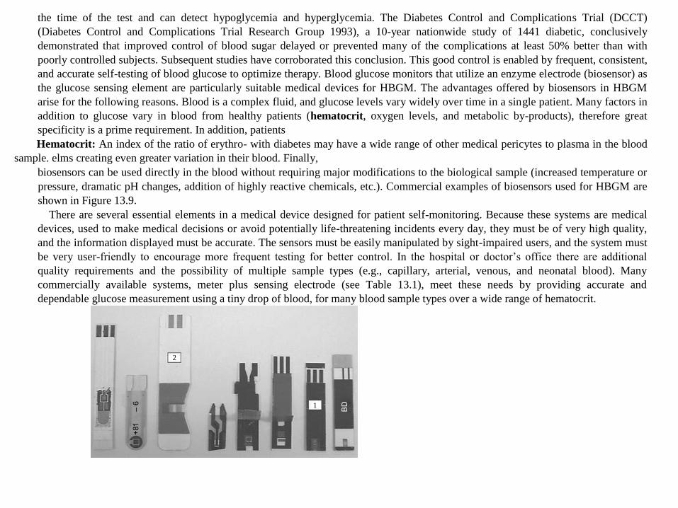
the time of the test and can detect hypoglycemia and hyperglycemia. The Diabetes Control and Complications Trial (DCCT)
(Diabetes Control and Complications Trial Research Group 1993), a 10-year nationwide study of 1441 diabetic, conclusively
demonstrated that improved control of blood sugar delayed or prevented many of the complications at least 50% better than with
poorly controlled subjects. Subsequent studies have corroborated this conclusion. This good control is enabled by frequent, consistent,
and accurate self-testing of blood glucose to optimize therapy. Blood glucose monitors that utilize an enzyme electrode (biosensor) as
the glucose sensing element are particularly suitable medical devices for HBGM. The advantages offered by biosensors in HBGM
arise for the following reasons. Blood is a complex fluid, and glucose levels vary widely over time in a single patient. Many factors in
addition to glucose vary in blood from healthy patients (hematocrit, oxygen levels, and metabolic by-products), therefore great
specificity is a prime requirement. In addition, patients
Hematocrit: An index of the ratio of erythro- with diabetes may have a wide range of other medical pericytes to plasma in the blood
sample. elms creating even greater variation in their blood. Finally,
biosensors can be used directly in the blood without requiring major modifications to the biological sample (increased temperature or
pressure, dramatic pH changes, addition of highly reactive chemicals, etc.). Commercial examples of biosensors used for HBGM are
shown in Figure 13.9.
There are several essential elements in a medical device designed for patient self-monitoring. Because these systems are medical
devices, used to make medical decisions or avoid potentially life-threatening incidents every day, they must be of very high quality,
and the information displayed must be accurate. The sensors must be easily manipulated by sight-impaired users, and the system must
be very user-friendly to encourage more frequent testing for better control. In the hospital or doctor’s office there are additional
quality requirements and the possibility of multiple sample types (e.g., capillary, arterial, venous, and neonatal blood). Many
commercially available systems, meter plus sensing electrode (see Table 13.1), meet these needs by providing accurate and
dependable glucose measurement using a tiny drop of blood, for many blood sample types over a wide range of hematocrit.
2
1

Commercial examples of biosensors available for HBGM. In some examples, the “top tape” has been removed to expose the
underlying electrode configuration. Examples 1 and 2 are the One Touch Ultra and the Accu-Check Advantage strip, which are
discussed in more detail in the text. Photograph kindly provided by Dr. Maria Teodorczyk, LifeScan, Milpitas, USA. (Reprinted from
French, C.E. and Cardosi, M.F. Fermentation Microbiology and Biotechnology, 2nd ed., CRC Press: Boca Raton, FL, 2007. With
permission)
TABLE 13.1
Examples of Commercially Available HBGM Test Kits
Company Meter
Test Strip
Required
Blood
Range in
mmol/L
Sample
Volume
in ml
Abbott Diabetes
Care
Precision QID MediSense G2 Sensor
electrodes
1.1–33.3 3.5
Therasense FreeStyle Classic FreeStyle 1.1–27.8 0.3
FreeStyle Mini FreeStyle 1.1–27.8 0.3
Bayer
Diagnostics
Ascensia Contour Ascensia Microfill 0.6–33.3 0.6
Ascensia Breeze Ascensia Autodisc (10-
test disc)
0.6–33.3 2.0–3.0
DiagnoSys
Medical
Prestige Qx Smart
System
Prestige Smart System 1.3–33.3 4
Hypoguard Supreme Plus Hypoguard Supreme 2.0–25.0 7
LifeScan OneTouch Ultra OneTouch Ultra 1.1–33.3 1
OneTouch
UltraSmart
OneTouch Ultra 1.1–33.3 1
Menarini
Diagnostics
GlucoMen Glyco GlucoMen Sensors 1.1–33.3 2
GlucoMen PC GlucoMen Sensors 1.1–33.3 2
Roche
Diagnostics
Accu-Chek
Compact
Accu-Chek Compact 0.55–33.3 1.5
Accu-Chek
Advantage
Accu-Chek 0.55–33.3 4

Accu-Chek Active Accu-Chek Active 0.55–33.3 2
Source: Data adapted from Diabetes UK website (http://www.diabetes.org.uk/products/index.html).
Enzymes used in Glucose Biosensors
Traditionally, two glucose oxidizing enzymes have been used in the manufacture of glucose biosensors for HBGM. Although both
enzymes oxidize the pyranose form of β-d-glucose (at the C1 position) to the corresponding lactone, they use different cofactors to
carry out the redox process. One is the flavoprotein GOx, which has FAD as a cofactor and the other is the quinoa-protein-dependent
glucose dehydrogenase (PQQ-GDH). Although both enzymes catalyze the oxidation of glucose, their biological properties differ, so
choice of enzyme is normally determined by the intended use of the sensor under specific clinical conditions.
GOx is a very specific enzyme (99.9% specific for β-d-glucose) that is commercially available in highly purified form and is
therefore the enzyme of choice in most devices. However, it does suffer from the problem of cross reactivity with oxygen, which
means that under situations of high oxygen partial pressure the reading obtained from the meter can be lower than expected.
Recognition of this fact is of clinical importance because high blood oxygen tensions are frequently observed in the critically ill and in
patients receiving oxygen therapy or undergoing surgery. Hence, changes in oxygen partial pressure (PO2) levels can falsely lower
glucose meter measurements and may mislead medical decision-making. Mechanisms by which oxygen affects GOx-based
amperometry test strips are suggested by the reactions in Table 13.2. Oxygen, a known natural electron acceptor, competes with
electron mediators such as ferrocenium used with the Precision PCx and Precision QID (Table 13.2, Equation 13.5) and ferricyanide
used with the Glucometer Elite (Table 13.2, Equation 13.13), for the re-oxidation of GOx/ FADH2. At high PO2, oxygen outcompetes
the electron mediator for the re-oxidation of GOx/FADH2, which results in reduced chemical reaction between the electron mediator
and GOx/FADH2, leading to fewer electrons produced. As a result, low glucose measurements are obtained at high PO2 levels.
On the other hand, PQQ-GDH does not react with oxygen, so it is suitable for use as the biocatalyst in the clinical scenarios
described above. However, the wild-type enzyme is not as specific as GOx, as illustrated by the kinetic data in Figures 13.10 and
13.11. Consequently, patients that have high levels of, for example, maltose in the blood (which could result as a side effect of
peritoneal dialysis) or have an inbred genetic disorder resulting in impaired carbohydrate metabolism would obtain an inaccurate high
reading when testing with glucose electrodes incorporating this enzyme. Because of the oxygen insensitivity of PQQ-GDH, there is
much commercial interest in producing

TABLE 13.2
Examples of Commercially Available Glucose Test Strips and the Associated Chemical Reactions
Test and Chemical Reaction Equation
Advantage H, Comfort Curve
Glucose + GD/PQQ → gluconic acid + GD/PQQH2 13.1 GD/PQQH2 + ferricyanide →
GD/PQQ + ferrocyanide 13.2
Ferrocyanide → ferricyanide + e– 13.3
Precision PCx, Precision QID
Glucose + GO/FAD → gluconic acid + GO/FADH2 13.4 GO/FADH2 + ferricinium → GO/FAD + ferrocene
13.5
Ferrocene → ferricinium + e– 13.6
GO/FADH2 + O2 → GO/FAD + H2O2 13.7
SureStep
Glucose + GO/FAD → gluconic acid + GO/FADH2 13.8
GO/FADH2 + O2 → GO/FAD + H2O2 13.9
H2O2 + MBTH-R + HRP → MBTH-R+ 13.10 MBTH-R+ + ANS + ½O2 → blue-green dye 13.11
Glucometer Elite
Glucose + GO/FAD → gluconic acid + GO/FADH2 13.12 GO/FADH2 + ferricyanide →
GO/FAD + ferrocyanide 13.13
Ferrocyanide → ferricyanide + e– 13.14
GO/FADH2 + O2 → GO/FAD + H2O2 13.15

Kinetic plot for wild-type soluble PQQ-GDH showing the relative enzymic activity (Units/ mg GDH protein) as a function of the
concentration of glucose, xylose, maltose, lactose, and galactose in the assay. Data kindly provided by Dr. Patricia Byrd, LifeScan,
Milpitas, USA. (Reprinted from French, C.E. and Cardosi, M.F. Fermentation Microbiology and Biotechnology, 2nd ed., CRC Press:
Boca Raton, FL, 2007.
With permission)
Km
(mM)
Vmax
(U/mg,
%)
Vmax/Km
(%)
Glucose
3-O-m-
glucose
Allose
Maltose
Lactose
Galactose
25.0
28.7
35.5
26.0
18.9
5.3
4610 (100)
3596 (78)
2997 (65)
2305 (50)
1982 (43)
277 (6)
184 (100)
123 (67)
84.6 (46)
88.3 (48)
105 (57)
52.3 (28)
Summary of the kinetics of sugar oxidation by wild-type soluble PQQ-GDH. (Reprinted from French, C.E. and Cardosi, M.F.
Fermentation Microbiology and Biotechnology, 2nd ed., CRC Press: Boca Raton, FL, 2007. With permission)

a mutant form of the enzyme that retains its nonreactivity to oxygen but shows improved specificity with respect to β-d-glucose.
Optical Biosensors
The optical Biosensor is a device, it utilizes the principle of optical measurements like fluorescence, absorbance etc. They used in fiber optics
and Optoelectronic transducers. The optical Biosensors are safe for non-electrical remote sensing of materials. In the transducer elements
primarily, optical Biosensors involves in the enzymes and antibodies. Usually the Biosensors is not required any reference sensors and the
comparative signals are generated by using the sampling sensor. The important Biosensors is described briefly.
Fiber Optic Lactate Biosensor
The working of the fiber optic lactate Biosensor is based on the measurement of change in oxygen concentration, molecular by identifying the
effects of oxygen in fluorescent dye. The following reaction is reduced by the enzyme lactate mono-oxygenase.
Fiber Optic Lactate Biosensor
The oxygen depends on the amount of fluorescence generated by the dyed film this is because of oxygen has a reducing effect on the
fluorescence. In the reaction mixture the concentration of lactate is increased, oxygen is utilized and as a result, there is a proportional decrease
in the quenching effect. Hence there is an increase in the fluorescence output can be measured.

Optical biosensors offer great advantages over conventional analytical techniques because they enable the direct, real-time and label-free
detection of many biological and chemical substances. Their advantages include high specificity, sensitivity, small size and cost-effectiveness.
Multiple advanced concepts and highly multidisciplinary approaches including microelectronics, microelectromechanical systems (MEMSs),
micro/Nano-technologies, molecular biology, biotechnology and chemistry are applied in the implementation of new optical biosensors. The
research and technological development of optical biosensors has experienced an exponential growth over the last decade. Optical biosensor
research and development has been directed mainly towards healthcare, environmental applications and the biotechnology industry. The
potential applications of biosensors in the fields of medicine, the environment and biotechnology are numerous, and each has its own
requirements in terms of the concentration of analyte to be measured, the required precision of output, the sample concentration required, the
time taken to complete the probe, the time necessary to enable reuse of the biosensor and the cleaning requirements of the system
Biosensors can be classified into different groups depending on the method of signal transduction: optical, electrochemical, thermometric,
piezoelectric or magnetic. Optical biosensors are the most commonly reported class of biosensors. Optical detection is performed by exploiting
the interaction of the optical field with a biorecognition element. Optical biosensing can be broadly divided into two general modes: label-free
and label-based. Briefly, in a label-free mode, the detected signal is generated directly by the interaction of the analyzed material with the
transducer. In contrast, label-based sensing involves the use of a label and the optical signal is then generated by a colorimetric, fluorescent or
luminescent method. Simple molecules such as glucose can be detected by enzymatic oxidation using label-assisted sensing. The glucose
analysis of blood is the most commercially successful (so far) application of a biosensor, i.e. the handheld glucose meter used by diabetics.
However, in some situations, e.g. antibody–antigen interaction where a label is conjugated with one of the bio reactants, labelling can alter the
binding properties and therefore introduce systematic error to the biosensor analysis.
An optical biosensor is a compact analytical device containing a biorecognition sensing element integrated with an optical transducer system the
basic objective of an optical biosensor is to produce a signal which is proportionate to the concentration of a measured substance (analyte). The
optical biosensor can use various biological materials, including enzymes, antibodies, antigens, receptors, nucleic acids, whole cells and tissues
as biorecognition elements. Surface plasmon resonance (SPR), evanescent wave fluorescence and optical waveguide interferometry utilize the
evanescent field near the biosensor surface to detect the interaction of the biorecognition element with the analyte. There are a huge number of
variations in the construction of optical biosensors and this review will focus on a few that have been selected based on their widespread
application and tending towards the detection of the most biologically relevant substances.

Surface plasmon resonance biosensors
The physical phenomenon of SPR was first observed in 1902. This observation of an esoteric optical phenomenon evolved through decades into
a full understanding of surface plasmon physics and in 1983 SPR was first successfully used to construct an SPR-based sensor to detect
biomolecular interactions. The first commercial SPR-based biosensor instrument was launched by Pharmacia Biosensor AB, which was later
renamed Bacoor. SPR instruments are currently produced by multiple manufacturers and the SPR-based biosensor is currently the predominant
optical biosensing method.
The SPR phenomenon occurs on the surface of metal (or other conducting materials) at the interface of two media (usually glass and liquid)
when it is illuminated by polarized light at a specific angle. This generates surface plasmons and consequently a reduction of the intensity of
reflected light at a specific angle known as the resonance angle. This effect is proportionate to the mass on the surface. A sensor gram can be
obtained by measuring the shift of reflectivity, angle or wavelengths against time. In all configurations, the SPR phenomenon enables direct,
label-free and real-time changes of refractive index at the sensor surface, which is proportionate to the biomolecule concentration. To measure a
ligand–analyte interaction, one interacting molecule must be immobilized on the sensor surface. A practical SPR instrument combines an optical
detector part, usually measuring intensity shift, a sensor chip with a gold surface and a layer enabling ligand immobilization, which is integrated
with a fluidics system enabling a flow-through operation.
The principle of SPR instrument (left) and typical SPR sensor gram showing the steps of an analytical cycle (right)
The SPR chip contains a functional layer which enables the immobilization of interacting molecules. Current instrumentation is dominated by
immobilization based on a self-assembled monolayer covered with a carboxymethylated dextran. This configuration enables the effective
immobilization of protein using N-hydroxysuccinimide (NHS) chemistry.
In a practical experiment one interaction component, e.g. the ligand, is permanently attached to the chip surface and another interacting
component, e.g. the analyte, flows over the surface and binds to the ligand. A typical SPR experiment is documented. The ligand (A) is
immobilized on the surface and interacts with the analyte (B). If this binding happens at a 1:1 ratio (Langmuir binding) then binding kinetics can
be described by eon. Experimental traces of response against time, then fitted and a practical result of SPR analysis are then kinetic constants
kon, koff and equilibrium constants Ka=kon/koff and Kd=1/Ka. The equilibrium dissociation constant Kd (mol · l−1) is generally used as a descriptive
parameter of ligand–analyte binding or any biomolecular interaction in general.
A+B→kon←koffAB
The detection of surface binding by SPR is a widely used concept. However, in practical life there are multiple other effects that can occur and
complicate SPR analysis, which include non-1:1 binding stoichiometry, avidity, non-specific absorption of ligand and mass transfer limitation
Dealing with those is well described in specialized monographs.
For practical applications there are three types of SPR analyses: kinetic analysis, equilibrium analysis and concentration analysis. Kinetic and
equilibrium analyses are commonly used to characterize any molecular interaction: ligand–analyte binding, antibody–antigen interaction,
receptor characterization etc. No comparable technology is available to characterize biomolecular interaction in real time without labelling and
therefore SPR is currently a prime tool for discovery research in biological sciences and pharmaceutical drug development. The SPR technique
also has multiple applications in the concentration analysis of any analyte if a ligand specific to it is available and can be immobilized on the
SPR chip. The concentration is then obtained by measuring direct binding or alternatively from the rate of binding in a mass transport limited
mode. Concentration analysis has wide application in multiple fields: clinical diagnostics, environmental analysis, food etc. An SPR biosensor
assay was used for the diagnosis of different stages of Epstein–Barr virus infection in clinical serum samples by the simultaneous detection of
the antibodies against three different antigens present in the virus. A soluble vascular endothelial growth factor receptor was determined using an
SPR chip with an immobilized ligand and a detection limit of 25 μg · l−1 was achieved. Rapid screening methods employing SPR portable
biosensors have great potential in food monitoring. The sensitive on-site analysis of antibiotics in milk samples was realized by a portable six-
channel SPR biosensor and the mycotoxin patulin was detected by an immuno-chemical SPR biosensor with a detection limit of 0.1 Nm. An
SPR biosensor was also used for the sensitive and anion-selective detection of As(III) with a limit of detection of 1.0 nM.
SPR imaging
SPR imaging (SPRi) takes the SPR analysis a step further by merging the sensitivity of SPR and spatial imaging in a microarray format allowing
the simultaneous study of multiple different interactions. SPRi allows simultaneously studying multiple different interactions on an array of
precisely patterned molecules. High throughput, sensitivity and obtaining the spatially resolved images of bio interactions open up a great future
for SPRi to be applied in clinical chemistry and medicine for the screening of biomarkers and therapeutic targets. For example, a successful
application of this method was the kinetic study of the binding between an immunosuppressive drug (FK506) and its target protein (FK506-
binding protein 12 (FKBP12)) in a high-throughput SPRi format with a detection limit of 0.5 nM.
A schematic illustration of the set-up for the SPR imaging (reprinted with permission
Localized surface plasmon resonance
Localized SPR (LSPR) is based on metallic nanostructures (MNPs) (Au, Ag, etc.) having unique optical properties which are not seen in larger
metal structures. A particularly striking example of such phenomenon is the red color of aqueous dispersions of colloidal gold particles, which is
a manifestation of LSPR. The optical phenomenon of LSPR occurs when incident light interacts with MNPs, the electromagnetic field of the
light induces collective electron charge oscillations confined in MNPs and the subsequent absorbance of light within the ultraviolet–visible (UV-
VIS) band. Thus, the major difference between SPR and LSPR is that induced plasmons oscillate locally on the nanostructure rather than along
the metal/dielectric interface.
Schematic diagrams showing the detection principle of plasmonic biosensors based on (A) SPR and (B) LSPR imaging (reprinted with
permission
The biosensing event based on LSPR spectral shifts, often referred to as ‘wavelength-shift sensing’, is caused by the surrounding dielectric
environmental change when a binding event occurs. However, properties of LSPR are greatly dependent on several factors, such as the material
used, dimension, shape and inter-particle distance of the MNPs involved. All these factors are reflected as a color change and absorption peak
shift. These parameters are a matter of sensor fabrication. Thus, by manipulating these parameters, it is possible to control/optimize LSPR sensor
properties such as sensitivity. The LSPR sensors are more adaptable in terms of biosensor fabrication compared with commercial SPR
biosensors. The LSPR sensors can either be fabricated by immobilizing MNPs on a substrate such as a glass slide, or an optical fiber, or by
simply suspending MNPs in solution to form a solution-phase-based LSPR sensor. Various optical geometries are used in LSPR sensors; the two
most common geometries and modes of operation are transmission and reflection modes.
Schematic illustration of LSPR transmission (left) and reflection (right) modes
Nowadays, LSPR-based sensing platforms are the next-generation plasmonic label-free methods. Current commercialized SPR instruments, such
as the well-known Bacoor™ series, are expensive and bulky, which limits the extent of their application. LSPR-based detection is more easily
miniaturized to increase throughput of detection and reduce operational costs. Characteristics required for state-of-the-art analytical devices,
such as LSPR-based portable screening tools, are robustness, sensitivity, specificity and low cost of production. They can serve as very effective
alternatives to numerous applications, for instance, in clinical diagnosis and food monitoring. It was shown that, compared with a reference
conventional high-resolution SPR biosensor, an LSPR biosensor can deliver the same performance as the SPR system while involving
significantly lower surface densities of interacting molecules. For example, an LSPR multiarray biosensor was used for screening antigen–
antibody interactions including immunoglobulins, C-reactive protein and fibrinogen with detection limits of 100 ng. In the study focused on the
clinical diagnostics of ovarian cancer, based on the detection of HE4 by the anti-HE4 antibody as a probe assembled on to the LSPR nanochip
surface, a broad linear range (10–10000 pM) was achieved with a detection limit of 4 pM. Mycotoxin ochratoxin A was quantitatively detected
by LSPR involving gold nanorods and an aptamer at concentrations lower than 1 nM.
Evanescent wave fluorescence biosensors
In these biosensors, the biological recognition and the consequent binding event occur within the confines of an evanescent wave. The
evanescent wave arises from the way light behaves when confined in an optical waveguide or fibers. Guided light is totally internally reflected
when it meets the interface of the waveguide/fiber and a surrounding medium with a lower index of refraction, as a result an electromagnetic
field called an evanescent wave extends out from the interface into the lower index medium. The evanescent wave decays exponentially with
distance from the surface, generally over the distance of 100 nm to approximately a wavelength. Since the evanescent wave is such a near-
surface phenomena, detection employing evanescent wave excitation to generate the fluorescent signal is surface-sensitive, meaning that only
fluorescent molecules near the surface are excited. This geometric limitation can help to minimize unwanted background signal from a bulk
sample while only enhancing the signal from fluorophores captured on the surface. A profuse variety of biosensors was developed based on this
principle with a wide array of applications ranging from clinical diagnostics to biodefence to food testing Moreover, with the recent
commercialization of a number of waveguide-based sensors it is anticipated that these sensors will make a major impact on healthcare-related
fields. The performance of this platform was assessed using >200 clinical samples from subjects comprising healthy individuals and those
positive for HIV, syphilis and hepatitis C, and excellent specificity was demonstrated. The evanescent wave aptamer-based fluorescence
biosensor was used for the rapid, sensitive and highly selective detection of 17β-estradiol, an endocrine-disrupting compound frequently
detected in environmental water samples. This biosensor was constructed as a portable system with the detection limit of 2.1 nM.
Schematic diagram of an evanescent wave planar optical waveguide chip
Bioluminescent optical fiber biosensors
This technique uses recombinant bioluminescent cells and the bioluminescent signal is transferred from the analyte by an optical fiber. An
Escherichia coli strain, genetically modified to emit a luminescent signal in the presence of genotoxic agents, was immobilized on to a fiber
optic and the optrode response to the genotoxin atrazine achieved a detection limit of 10 pg. A live cell array bioluminescent biosensor
fabricated by immobilizing bacterial cells on the optical fibers arranged in a high-density array of microwells was developed. Each microwell
accommodated a single genetically engineered bacterium responding to a specific analyte and the array biosensor enabled the multidetector of
genotoxins.

Optical waveguide interferometric biosensors
An integrated planar optical waveguide interferometric biosensor is a combination of evanescent field sensing and optical phase difference
measurement methods. By probing the near-surface region of a grating sensor area with the evanescent field, any change of the refractive index
of the probed volume induces a phase shift of the guided mode compared with a reference field, typically of a mode propagating through the
reference arm of the same waveguide structure. The interfering fields of these modes produce an interference signal detected at the sensor's
output, whose alteration is proportional to the refractive index change and the signal is related to the concentration of the analyte. This
technique, also called resonant waveguide grating (RWG), is suitable for detecting the redistribution of cellular contents, studying cellular
responses and cellular processes, and was also applied to the detection of the avian influenza virus.
Ellipsometric biosensors
An ellipsometric biosensor measures changes in the polarization of light when it is reflected from a surface. This platform was applied in
detecting the binding of influenza A virus strains with a panel of glycans of diverse structures. The apparent equilibrium dissociation constants
(avidity constants, 10–100 pM) were used as characterizing parameters of viral receptor profiles. Microarray biosensors based on total internal
reflection imaging ellipsometry for the detection of the serum tumor biomarker CA19-9 had an estimated detection limit of CA19-9 of
18.2 units · ml−1, which is lower than the cut-off value for a normal level.
Reflectometric interference spectroscopy biosensors
Reflectometric interference spectroscopy (RIfS) is a label-free and time-resolved method where the simple optical set-up is based on white light
interference at thin layers. Changes in the phase and amplitude of polarized light provides information about the thickness and refractive index
of the adsorbed protein layer. This method was used for the detection and quantification of diclofenac in bovine milk and the obtained limit of
detection was 0.112 μg · l−1 in the complex milk matrix. An RIfS biosensor for the detection of circulating tumor cells was capable of the
selective detection of cancer cells within a concentration range of 1000–100000 cells · ml−1 with a detection limit of <1000 cells · ml−1.
Surface-enhanced Raman scattering biosensors
Surface-enhanced Raman scattering (SERS) is a biosensing technique which enhances the intensity of the vibration spectra of a molecule by
several orders of magnitude when it is near Nano-roughened metallic surfaces or nanoparticles made of gold or silver. A SERS-active surface

fabricated on the tip of the optical fibers was applied to the sensitive detection of cancer proteins (∼100 pg) in a low sample volume (∼10 nl). A
SERS biosensor for the fast and sensitive detection of a protein biomarker of endocrine-disrupting compounds in an aquatic environment, with a
limit of detection of 5 ng · l−1, has been reported.
Fiber optic biosensor
The optical fiber is flexible and has small wires generally made from glass or plastic in different configuration, shape, and size. It can transmit
light signals for long distances with minimum lost value. The optical fiber is convenient for harsh and hazardous environments, because of their
remarkably strong, flexible and durable structures. It is non-electrical; therefore, it can be used in various damaged electric current applications.
Optical fibers are commonly used because of high quality and its low cost for sensing applications. Particularly, the main attractive properties of
optical fibers can permit transmission of multiple signals synchronously and by this means it can obtain multiple capabilities for sensing of
analyte
The Fiber Optic Biosensor have some advantages and disadvantages which are shown below.
The Advantages of Fiber Optic Biosensor
1. There is no need reference electrode in the system 2. It can be easily moved, because there is no reagent in contact of any optical fiber 3.
There are no electrical safety hazards and electrical interference 4. It is less dependent than temperature compared with electrode 5. It can be
found in-vivo measurement applications because of easy miniaturization 6. Multiple analytes can be determined thanks to guide the light in
different wavelengths at the same time. 7. It can be used for the most of chemical analytes because of its spectroscopic properties.
The Disadvantages of Fiber Optic Biosensor
1. The life time of the reagents can be short under incident light 2. Because of the diffusion of analytes, it may cause slow response time 3.
Fiber Optic Biosensor only works for specific reagent. 4. Optimized commercial accessories have limited availability when using them
with optical fibers.
Optical Biosensors for Blood Glucose
For the diabetes patients the blood glucose is more important to monitor. In this simple technique is used, i.e. Paper strips saturated with the
reagents it contains glucose oxide, Horseradish Peroxidase and a Chromogen. The following reactions take place. Using the portable reflectance
meter, it can measure the intensity of the color of the dye. In the world wide, the glucose strip industry is very high. The calorimetric test strips
of cellulose covered with the suitable enzymes and reagents are in use for the view of more blood and the urine parameters.

The other optical fiber Biosensors are used in the devices of optical Biosensing it measures the p CO2 and in critical care and in surgical
monitoring.
Affinity biosensors
Affinity biosensors: devices in which bio-recognition molecules bind analyte molecules leading to formation or dissociation of
complex, causing a physicochemical change that is detected by a transducer
Receptor molecules: i) antibodies ii) DNA iii) receptors

Different between affinity and enzyme biosensors

Design parameters for affinity biosensors
Enzyme Linked ImmunoSorbent Assay (ELISA)

1) Immobilization of capture antibodies
2) Addition of samples
3) Addition of detection antibodies (with an enzyme label)
4) Addition of enzyme substrate for colour development
5) Measure by optical transducers
