buckling of circumferentially corrugated cylinders - wit … pressure, a thin-walled circular...
TRANSCRIPT
Buckling of circumferentially corrugated cylinders
under uniform external pressure
C.T.F. Ross," G. Apor,*) S.R Claridge*
"Department of Mechanical and Manufacturing Engineering,
University of Portsmouth, Portsmouth, Hampshire PO1 3DJ, UK
Xavier University, Cagayan de Oro City, Philippines
Abstract
The paper describes a theoretical and an experimental investigation into thebuckling of three circumferentially corrugated circular cylinders under uniformexternal pressure. The experimental results showed that the vessels buckledthrough general instability.
The theoretical analysis was of a semi-empirical nature, which involved thefinite element method and an elastic knockdown factor to cater for inelasticinstability.
1 Introduction
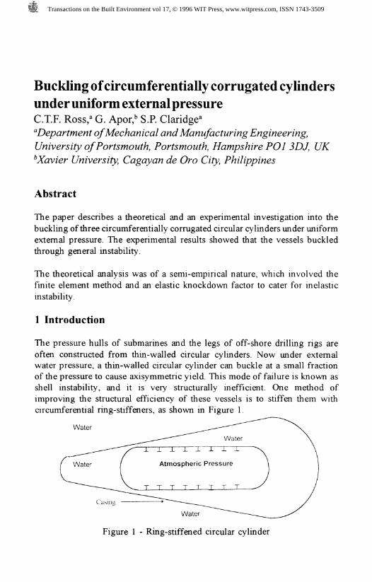
The pressure hulls of submarines and the legs of off-shore drilling rigs areoften constructed from thin-walled circular cylinders. Now under externalwater pressure, a thin-walled circular cylinder can buckle at a small fractionof the pressure to cause axisymmetric yield. This mode of failure is known asshell instability, and it is very structurally inefficient. One method ofimproving the structural efficiency of these vessels is to stiffen them withcircumferential ring-stiffeners, as shown in Figure 1.
Water
J . J L - L - L J - J - - L - L
Atmospheric Pressure
Water
Figure 1 - Ring-stiffened circular cylinder
Transactions on the Built Environment vol 17, © 1996 WIT Press, www.witpress.com, ISSN 1743-3509

104 Engineering Integrity
In Figure 1, it can be seen that the ring-stiffened pressure hull is surroundedby a hydrodynamic hull, where the latter has water pressure on both itsinternal and external surfaces. Thus, as the hydro-dynamic hull is in a stateof hydrostatic stress, it is unlikely to fail due to the effects of hydrostaticpressure alone.
If the ring stiff en ers are not strong enough, the entire ring-shell combinationcan buckle bodily, through general instability. In 1987, Ross [1] presented analternative design to the ring-stiffened vessel, as shown in Figure 2.
Water
Casing
Figure 2 - Circumferentially Corrugated Pressure Hull
From Figure 2, it can be seen that the pressure hull was a circumferentiallycorrugated vessel. Using two mathematical models, Ross showed that thecorrugated pressure hull was structurally more efficient than a ring-stiffenedvessel of the same weight and volume. In one case, the corrugated vessel hadnearly twice the strength of its ring-stiffened equivalent.
In fact, Kuan-Ya et al [2] showed that the corrugated cylinders could be madeeven more structurally efficient by increasing the cone angles to certainoptimum values. The work reported so far is of a theoretical nature, andexperimental work to verify the theoretical mode of failure was carried out byRoss et al [3 to 5], see Figure 3.
Figure 3 - General instability of corrugated circular cylinders
Transactions on the Built Environment vol 17, © 1996 WIT Press, www.witpress.com, ISSN 1743-3509
Engineering Integrity 105
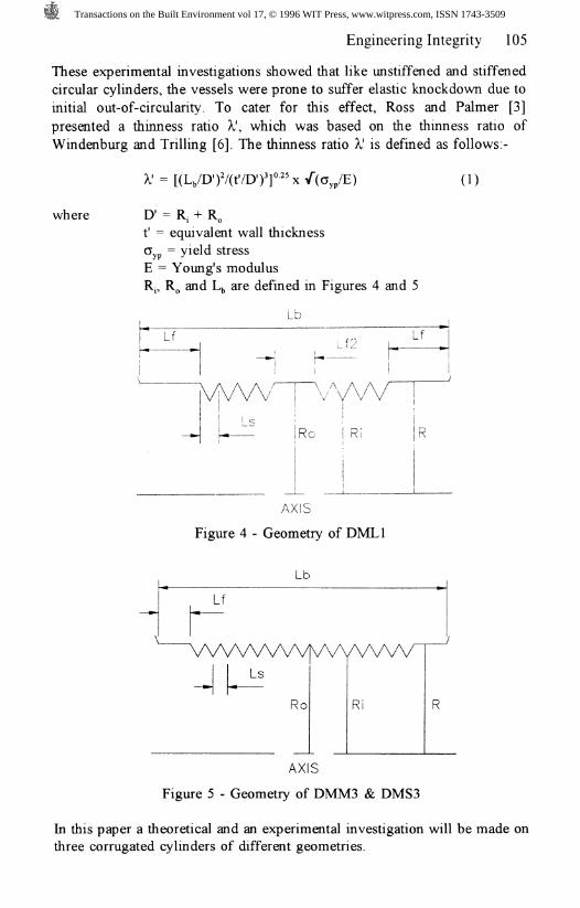
These experimental investigations showed that like un stiffened and stiffenedcircular cylinders, the vessels were prone to suffer elastic knockdown due toinitial out-of-circulanty. To cater for this effect, Ross and Palmer [3]presented a thinness ratio X', which was based on the thinness ratio ofWindenburg and Trilling [6]. The thinness ratio X' is defined as follows:-
(1)
where D' = R, + R^t' = equivalent wall thicknessGyp = yield stressE = Young's modulusRj, RO and L,, are defined in Figures 4 and 5
AXIS
Figure 4 - Geometry of DML1
AXIS
Figure 5 - Geometry of DMM3 & DMS3
In this paper a theoretical and an experimental investigation will be made onthree corrugated cylinders of different geometries.
Transactions on the Built Environment vol 17, © 1996 WIT Press, www.witpress.com, ISSN 1743-3509
106 Engineering Integrity
2 Experimental Apparatus
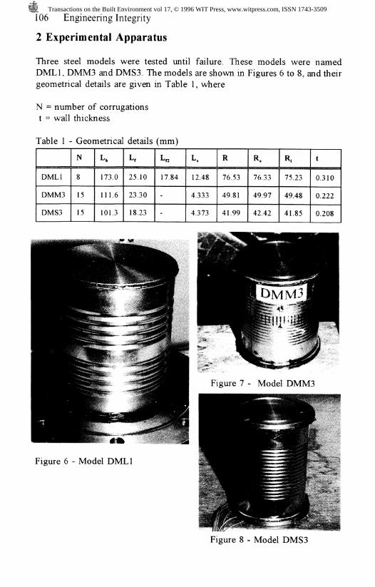
Three steel models were tested until failure. These models were namedDML1, DMM3 and DMS3. The models are shown in Figures 6 to 8, and theirgeometrical details are given in Table 1, where
N = number of corrugationst = wall thickness
Table 1 - Geometrical details (mm)
DML1
DMM3
DMS3
N
8
15
15
Lt
173.0
111.6
101.3
L,
25.10
23.30
18.23
L«
17.84
-
-
L,
12.48
4.333
4.373
R
76.53
49.81
41.99
R.
76.33
49.97
42.42
R,
75.23
49.48
41.85
t
0.310
0.222
0.208
Figure 7 - Model DMM3
Figure 6 - Model DML1
Figure 8 - Model DMS3
Transactions on the Built Environment vol 17, © 1996 WIT Press, www.witpress.com, ISSN 1743-3509

Engineering Integrity 107
All models were manufactured by Del Monte Phillipines Incorporated; theirmaterial properties were as follows:-
Modulus (E)Density ( p)Poisson's ratio (v)
= 190 GPa= 7800 kg/m*= 0.3 (assumed)
= 344MPa= 453 MPa
(DMS3) = 475 MPa
The longitudinal profiles of the vessels were measured by a Mitutoyo co-ordinate measuring machine. The profiles were of a sinusoidal nature, but forthe theoretical analysis, it was convenient to represent each corrugation withtwo truncated finite element conical shell elements; previous work [7] hasfound this to be satisfactory. The ends of the vessels were blocked off by enddisc caps, sealed by a household silicone sealant, as shown in Figures 6 to 8.
The out-of-circulanty of the vessels is given in Table 2. Out-of-circularity isdefined as maximum difference between the maximum inward and outwarddeviations of the external surface from a mean circle (using a least squares fit)
Table 2 - Out-of-circulanty measurements (mm)
DML1
Middle
1.7752
DMM3
Top
1.6511
Bottom
1.6458
DMS3
Top
0.6550
Bottom
1.2767
3 Experimental Procedure
The models were tested in a test tank shown in Figure 9. Water was used asthe pressure raising fluid, with the aid of a manually-operated hydraulic pump.
Gasket seal
Atmospheric ____-Pressure
End cap.
Water underpressure
Figure 9 - Test Tank and Model
Transactions on the Built Environment vol 17, © 1996 WIT Press, www.witpress.com, ISSN 1743-3509

108 Engineering Integrity
Line losses were negligible, as the hose was only 2m in length, and the pumpwas manually operated. Prior to raising the pressure, a bleed screw, was leftopen, so that any trapped air could be pumped out. When the trapped air wasremoved, the bleed screw was sealed and the pressure tests commenced. Theexperimental boundary conditions for each vessel was probably in-betweenclamped and simply-supported.
3.1 Testing the Models
Each one of the three models had attached to it, several linear strain gaugesplaced in the circumferential direction. The purpose of these strain gauges wasto observe the circumferential buckling patterns, throughout each test. Thestrain gauges were spaced at equidistances apart. Ten strain gauges wereattached to DML1, the largest of the three models, eight strain gauges toDMM3 and six strain gauges to DMS3, the smallest of the three models.
Each model was tested to destruction. Model DML1 collapsed at a pressureof 2.55 bar with the formation of four lobes. Model DMM3 collapsed to apressure of 1.931 bar and model DMS3 collapsed at a pressure of 3.172 bar,the number of lobes corresponding to each of these two buckling pressure wasnot as easily determined as for model DML1.
Plots of strain recording for various values of pressure are shown in Figures10 to 12, and pictures of the collapsed models are shown in Figures 13 to 15.
400 -
200-
00)c73CDcc-200c'ro
^-400
-600 -
onn-ouU -*
P/
9. $. ^ • 4-rLS- ^ =£-~-u 'x/jkr — ll" V— -« -+-*• ' ;p -x;r > -I ;£=: *
;f -/' f s-;'
V'3
= '
;' /ri
1 2 3 4 5 6 7 8 9 1 0Strain Gage Location
— •-0 bar
0.345 bar
0.689 bar
1.034 bar
1 379 bar-•-1.517 bar
1.793 bar
1.931 bar
2.207 bar
9 /m har-0-2.483 bar
Figure 10 - Strain recordings for DML1 Buckling Test (micro-strain)
Transactions on the Built Environment vol 17, © 1996 WIT Press, www.witpress.com, ISSN 1743-3509

CO
cu<DryC.(U
200 j
100 -II
0 i| g
_1QQ A -* r— ="
!T '
/ • T '
Szzz # ^ ^ ^ ^ 5 Iifcr~~~ v ^ r-~« \c _ i
00-200 -f
1 2 3 4 5 6 7Strain Gage Location
-#- 0.345 bar -H- 0.689 bar -»- 0.828 bar -v- 1.103 bar II -e- 1.379 bar -»- 1.655 bar -v- 1.793 bar
Figures 11 - Strain recordings for DMM3 Buckling Test (micro-strain)
1000 , -
500
-500 -
-10002 3 4
Strain Gage Location
• 0.345 bar -&• 0.689 bar o 1.379 bar -:-:- 1.793 bar — 2.345 bars 2.758 bar - ?- 3.034 bar « 3.172 bar -v- 1.724 bar
Figure 12 - Strain recordings for DMS3 Buckling Test (micro-strain)
Figure 13 - Collapsed model DMM3
Transactions on the Built Environment vol 17, © 1996 WIT Press, www.witpress.com, ISSN 1743-3509

110 Engineering Integrity
Figure 14 - Collapsed model DML1 Figure 15 - Collapsed model DMS3
As the strain recordings for DML1 were well below the yield strain, it islikely that these vessels buckled elastically. In the case of DMM3 and DMS3,the strain recordings were well past the yield strain, hence, these vesselsbuckled inelastically, and were more likely to suffer elastic knockdown.
4 Theoretical Analysis
The theoretical buckling pressures were calculated by a computer programcalled CONEBUCK [8], which is based on the finite element method. Thethin-walled truncated conical element was used and is reported elsewhere(Ross [9]). The theoretical buckling pressures (PJ were found to be 3.267 bar,3.113 bar and 4.0 bar for DML1, DMM3 and DMS3 respectively.
4.1 Design procedure
The design procedure, therefore, is to calculate the theoretical bucklingpressure P and the thinness ratio A,', and to divide P,, by the elasticknockdown factor, namely (P,/P), to obtain the actual collapse pressure.The elastic knockdown factor will be obtained from a design curve, whensufficient experimental results are available, where X' will be plotted againstPc/Pexp f°r each model, where, P^ = experimental buckling pressure
To obtain the design pressure, it will be necessary to divide the collapsepressure by a large safety factor.
Transactions on the Built Environment vol 17, © 1996 WIT Press, www.witpress.com, ISSN 1743-3509
Engineering Integrity 111
4.2 Calculation of thinness ratio
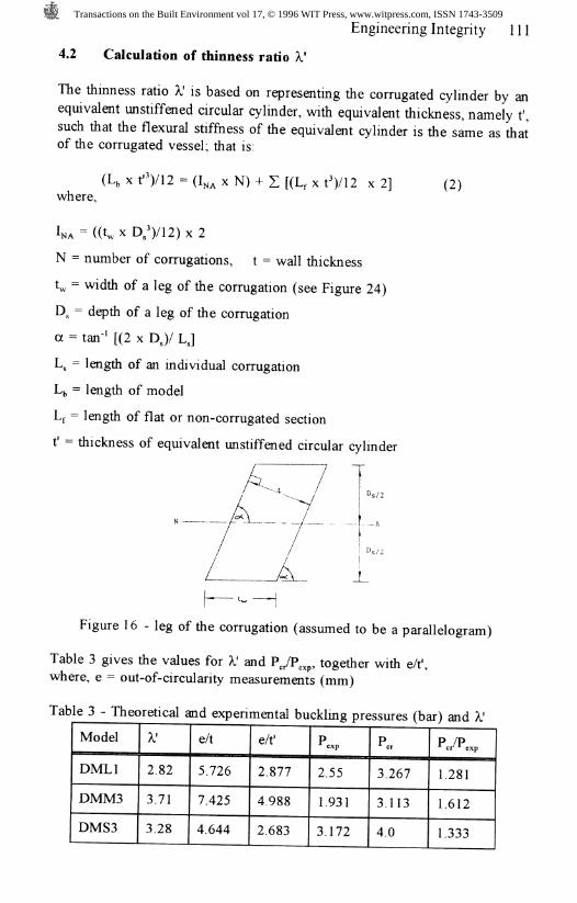
The thinness ratio A,' is based on representing the corrugated cylinder by anequivalent unstlffened circular cylinder, with equivalent thickness, namely t',such that the flexural stiffness of the equivalent cylinder is the same as thatof the corrugated vessel; that is:
x t")/12 = (1^ x N) + Z [(Lf x t')/12 x 2]where,
N = number of corrugations, t = wall thickness
L = width of a leg of the corrugation (see Figure 24)
D,, = depth of a leg of the corrugation
a = tan'* [(2 x D,)/ LJ
Lg = length of an individual corrugation
Ly = length of model
Lf = length of flat or non-corrugated section
t' = thickness of equivalent unstiffened circular cylinder
Ds/2
(2)
_L
Figure 16 -leg of the corrugation (assumed to be a parallelogram)
Table 3 gives the values for X' and P,/P , together with e/t',where, e = out-of-circularity measurements (mm)
Table 3 - Theoretical and experimental buckling pressures (bar) and A,'
Model
DML1
DMM3
DMS3
A;
2.82
3.71
3.28
e/t
5.726
7.425
4.644
e/t'
2.877
4.988
2.683
Pexp
2.55
1.931
3.172
PC,
3.267
3.113
4.0
pyp*c/i exp
1.281
1.612
1.333
Transactions on the Built Environment vol 17, © 1996 WIT Press, www.witpress.com, ISSN 1743-3509

112 Engineering Integrity
From Table 3, it can be seen that the model DMM3 had the largest value ofelastic knockdown, and this was due to the fact that it also had the largestvalue of e/f. Similarly, as both K' and e/t' were similar for DML1 and DMS3,their elastic knockdown factors were similar. Table 4 compares these resultswith results obtained from other recent tests.
Table 4 - Comparisons of 1', e/t' and P,/P
Model
DML1
DMM3
DMSB
DF
MBS
MBL
CA
e/t'
2.877
4.988
2,683
0.185
0.185
0.365
0.46
X'
2.82
3.74
3.28
3.57
2.67
3.53
2.73
P /Pcr exp
1.28
1.61
1.33
1.15
1.61
1.69
1.45
5 Conclusions
The results have shown that it is possible to replace a ring stiffened pressurehull of a submarine with a similar corrugated vessel. This should beparticularly attractive if the hull is to be made from carbon or glass fibrecomposite material, as it should be easier to construct such a vessel incorrugated form, rather than as a ring stiffened vessel. Further research isrequired to determine the loss of buckling resistance due to initial out-of-cicularity of the cylinders.
References
1. Ross,CTF, A novel submarine press, hull design, J.Ship Res.,31,186-188, 1987.
2. Kuan-Ya Yuan, Cho-Chung Liang and Yung-Chung Me, Investigationof the cone angle of a novel swedged-stiffened pressure hull, J ShipResearch, 35, 83-86, 1991.
3. Ross,CTF and Palmer,A, General instability of swedge-stiffenedcircular cylinders under uniform external pressure, J Ship Research,37, 77-85, 1993.
4. Ross,CTF and Humphries,M, The buckling of corrugated circularcylinders under uniform external pressures, J. Thin-Walled Structures,17, 259-271, 1993.
Transactions on the Built Environment vol 17, © 1996 WIT Press, www.witpress.com, ISSN 1743-3509
Engineering Integrity 113
5. Ross,CTF and Heigl,T, Buckling of corrugated axisymmetnc shellsunder uniform external pressure, Proc ASME Conf on StructuralDynamics and vibrations, PD-Vol 70, 199-205, 1995.
6. Widenburg,DF and Trilling, C, Collapse by instability of thincylindrical shells under ext. press., trans ASME, 11, 819-825, 1934
7. Ross,CTF and Johns, T, Vibration of hemi-ellipsoidal axisymmetncdomes submerged in water, Proc IMechE, 200, 389-298, 1986.
8 Ross,CTF, Finite element programs for axisymmetric problems inengineering, Ellis Horwood, Chichester, 1984.
9. Ross,CTF, Pressure vessels under ext. pressure, Chapman and Hall,London, 1990.
Transactions on the Built Environment vol 17, © 1996 WIT Press, www.witpress.com, ISSN 1743-3509