bucklingof thin-walledcircularcylinders - … · · 2013-08-31bucklingof...
TRANSCRIPT
NASASPACEVEHICLEDESIGNCRITERIA(STRUCTURES)
NASA SP-8007
BUCKLINGOF
THIN-WALLEDCIRCULARCYLINDERS
SEPTEMBER 1965
Rev ised
AUGUST 1968
NATIONAL AERONAUTICS AND SPACE ADMINISTRATION
https://ntrs.nasa.gov/search.jsp?R=19690013955 2018-06-10T22:22:33+00:00Z

For sale by the Clearinghouse for Federal Scientific and Technical Information
Springfield, Virginia 22151 - Price $3.00
FOREWORD
NASA experience has indicated a need for uniform criteria for the design of space
vehicles. Accordingly, criteria are being developed in the following areas of technology:
Environment
Structures
Guidance and Control
Chemical Propulsion.
Individual components of this work will be issued as separate monographs as soon as
they are completed. A list of all previously issued monographs in this series can be
found on the last page of this document.
These monographs are to be regarded as guides to design and not as NASA
requirements, except as may be specified in formal project specifications. It is
expected, however, that the criteria sections of these documents, revised as experience
may indicate to be desirable, eventually will become uniform design requirements for
NASA space vehicles.
This monograph was prepared under the cognizance of the Langley Research Center.
The Task Manager was A. L. Braslow. The authors were V. I. Weingarten and P. Seide
of the University of Southern California and J. P. Peterson of NASA Langley Research
Center. A number of other individuals assisted in developing the material and reviewing
the drafts. In particular, the significant contributions made by E. H. Baker of North
American Rockwell Corporation, C.D. Babcock, Jr., of California Institute of
Technology, R.F. Crawford of Astro Research Corporation, J.B. Glassco of
McDonnell Douglas Corporation, A. Kaplan of TRW Systems, M. H. Kural of Lockheed
Missiles & Space Company, and J. Mayers of Stanford University, are hereby
acknowledged.
Comments concerning the technical content of these monographs will be welcomed by
the National Aeronautics and Space Administration, Office of Advanced Research and
Technology (Code RVA), Washington, D.C. 20546.
August 1968
111

CONTENTS
,
2.
3.
.
SYMBOLS ............................ vii
INTRODUCTION ........................ 1
STATE OF THE ART ..................... 2
CRITERIA ............................ 3
3.1 General ........................... 3
3.2 Guides for Compliance ................. 3
RECOMMENDED PRACTICES ...............
4. l Scope .............................
4.2 Isotropic Unstiffened Cylinders ............
4.2.1
4.2.2
4.2.3
4.2.4
4.2.5
Axial Compression ...............
Bending ......................
External Pressure ................
Torsion ......................
Combined Loads ................
4.3
3
3
4
4
7
8
11
13
Circular Cylinders in AxialCompression and Bending .... 13Circular Cylinders in AxialCompression and ExternalPressure .................. 13Circular Cylinders in Axial
Compression and Torsion .... 14Internally Pressurized Circular
Cylinders in AxialCompression .............. 14Internally Pressurized CircularCylinders in Bending ........ 15Internally Pressurized Cylindersin Axial Compression & Bending 16
Orthotropic Cylinders .................. 16
4.3.1 Axial Compression ............... 16
4.3.2 Bending ...................... 19
4.3.3 External Pressure ................ 19
4.3.4 Torsion ...................... 21
v
Combined Bending and Axial
Compression ................... 21
Elastic Constants ................ 22
4.3.6.1 Stiffened Multilayered
Orthotropic Cylinders ...... 22
4.3.6.2 Isotropic Cylinders with
Stiffeners and Rings ........ 25
4.3.6.3 Ring-Stiffened Corrugated
Cylinders ............... 26
4.3.6.4 Waffle-Stiffened Cylinders . . . 26
4.3.6.5 Special Considerations ...... 26
4.4 Isotropic Sandwich Cylinders ............. 27
4.4.1 Axial Compression ............... 28
4.4.2 Bending .... .................. 32
4.4.3 Lateral Pressure ................. 32
4.4.4 Torsion ...................... 33
4.5 Cylinders with an Elastic Core ............ 35
4.5.1
4.5.2
4.5.3
4.5.4
4.6 Design of Rings
Axial Compression ............... 35
External Pressure ................ 36
Torsion ...................... 39
Combined Axial Compression and
Lateral Pressure ................. 40
...................... 41
REFERENCES .......................... 43
NASA SPACE VEHICLE DESIGN CRITERIA
MONOGRAPHS ISSUED TO DATE ............ 49
vi
SYMBOLS
As,Ar
BI
b
be
Cx,Cy,Cxy,Kxy
c
D
Dq
Dx,Dy
Dxy
D1
stiffener and ring area, respectively
extensional stiffness of isotropic sandwich wall
stiffener spacing
effective width of skin between stiffeners
coupling constants for orthotropic cylinders
coefficient of fixity in Euler column formula
wall flexural stiffness per unit width,Et 3
12(1 --/a 2)
transverse shear-stiffness parameter for isotropic sandwich wall,
h zGxz 1
h -- -_ (h + t2)
bending stiffness per unit width of wall in x- and y-direction,
respectively, Dx = Dy = D for isotropic cylinder
modified twisting stiffness of wall; Dxy = 2D for isotropic cylinder
flexural stiffness of isotropic sandwich wall, Esth22(1 - ta2)
d
E
Ec
ER
ES
Er,Es
Esec
Etan
Ex,Ey
ring spacing
Young's modulus
Young's modulus of elastic core
reduced modulus
Young's modulus of face sheet of sandwich
Young's modulus of rings and stiffeners, respectively
secant modulus for uniaxial stress-strain curve
tangent modulus for uniaxial stress-strain curve
Young's modulus of orthotropic material in x-
respectively
and y-direction,
vii
Ex,Ey,Exy
E Z
G
Gs,Gr
Gxy
Gxy
Gxz,Gyz
h
I
Ir,ls
Jr,Js
kp
kpc
kx
ky
kxy
£
M
Mpress
Mp=0
Mt
m
No
Nx
extensional stiffness of wall in x- and y-direction, respectively;
Et - _ #EtE x = Ey - 1 - #2, Exy 1 - tt z for isotropic cylinder
Young's modulus of sandwich core in direction perpendicular to face
sheet of sandwich
shear modulus
shear modulus of stiffeners and rings, respectively
inplane shear modulus of orthotropic material
shear stiffness of orthotropic or sandwich wall in x-y plane; Gxy -- Gt
for isotropic cylinder
shear modulus of core of sandwich wall in x-z and y-z planes,
respectively
depth of sandwich wall measured between centroids of two face
sheets
moment of inertia per unit width of corrugated cylinder
moment of inertia of rings and stiffeners, respectively, about their
centroid
beam torsion constant of rings and stiffeners, respectively
buckling coefficient of cylinder subject to hydrostatic pressure,
pr £2/rr2 D
buckling coefficient of cylinder with an elastic core subject to lateral
pressure, pr 3/D
buckling coefficient of cylinder subject to axial compression,
Nx £=/rr 2 D or Nx £2/rr =D,
buckling coefficient of cylinder subject to lateral pressure, Ny£ 2/rr 2 D
or Ny£ 2/rr 2D 1
buckling coefficient of cylinder subjected to torsion, Nxy_ 2/rr2D or
NxyJ_ 2/rr 2 DI
length of cylinder
bending moment on cylinder
bending moment at collapse of a pressurized cylinder
bending moment at collapse of a nonpressurized cylinder
twisting moment on cylinder
number of buckle half waves in tile axial direction
2 E. hV/_ _/_2 r
axial load per unit width of circumference for cylinder subjected to
axial compression
viii

Ny
Nxy
n
P
Ppress
Pp=0
P
R
Rb
R c
Rp
Rt
r
S
t
tf
tk
tl,tz
x,y,z
Z
circumferential load per unit width of circumference for cylinder
subjected to lateral pressure
shear load per unit width of circumference for cylinder subjected to
torsion
number of buckle waves in the circumferential direction
axial toad on cylinder
axial load on pressurized cylinder at buckling
axial load on nonpressurized cylinder at buckling
pressure, usually critical pressure
_r2Dshear flexibility coefficient,
I_2 Dq
ratio of bending moment on cylinder subjected to more than one
type of loading to the allowable bending moment for the cylinder
when subjected only to bending
ratio of axial load in cylinder subjected to more than one type of
loading to the allowable axial load for the cylinder when subjected
only to axial compression
ratio of external pressure on cylinder subjected to more than one
type of loading to the allowable external pressure for the cylinder
when subjected only to external pressure
ratio of torsional moment on cylinder subjected to more than one
type of loading to the allowable torsional moment for the cylinder
when subjected only to torsion
radius of cylinder
cell size of honeycomb core (see eq. 92)
skin thickness of isotropic cylinder; thickness of corrugated cylinder
effective thickness of corrugated cylinder, area per unit width of
circumference
face thickness of sandwich cylinder having equal thickness faces
skin thickness of k th layer of layered cylinder
facing-sheet thicknesses for sandwich construction having faces of
unequal thickness
coordinates in the axial, circumferential, and radial directions,
respectively
172 i72curvature parameter; -_/ri--_2 for isotropic cylinder, 2-)--_1_--_ 2
for isotropic sandwich cylinder
ix
_k
Zs,Z r
7
_y
5
5k
r/
/a
#c
#x,P.y
Op
0 x
Oy
I"
rcr
rxy
distance of center of k th layer of layered cylinder from reference
surface (positive outward)
distance of centroid of stiffeners and rings, respectively, from
reference surface (positive when stiffeners or rings are on outside)
buckle aspect ratio ( n_ tVIr I111!
correlation factor to account for difference between classical theory
and predicted instability loads
distance of reference surface from inner surface of layered wall
increase in buckling correlation factor due to internal pressure
ratio of core density of honeycomb sandwich plate to density of face
sheet of sandwich plate
distance of centroid of k th layer of layered cylinder from inner
surface
plasticity reduction factor
Poisson's ratio
Poisson's ratio of core material
Poisson's ratios associated with stretching of an orthotropic material
in x- and y-directions, respectively
critical axial stress for a cylinder with an elastic core
axial stress
circumferential stress
shear stress
torsional buckling stress of an unfilled cylinder
shear stress in the x-y plane
BUCKLING OF THIN-WALLEDCIRCULAR CYLINDERS
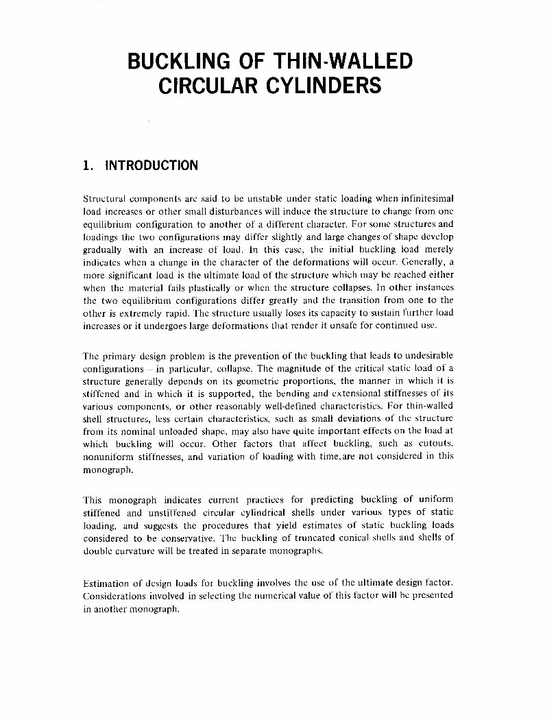
1. INTRODUCTION
Structural components are said to be unstable under static loading when infinitesimal
load increases or other small disturbances will induce the structure to change from one
equilibrium configuration to another of a different character. For some structures and
loadings the two configurations may differ slightly and large changes of shape develop
gradually with an increase of load. In this case, the initial buckling load merely
indicates when a change in the character of the deformations will occur. Generally, a
more significant load is the ultimate load of the structure which may be reached either
when the material fails plastically or when the structure collapses. In other instances
the two equilibrium configurations differ greatly and the transition from one to the
other is extremely rapid. The structure usually loses its capacity to sustain further load
increases or it undergoes large deformations that render it unsafe for continued use.
The primary design problem is the prevention of the buckling that leads to undesirable
configurations - in particular, collapse. The magnitude of the critical static load of a
structure generally depends on its geometric proportions, the manner in which it is
stiffened and in which it is supported, the bending and extensional stiffnesses of its
various components, or other reasonably well-defined characteristics. For thin-walled
shell structures, less certain characteristics, such as small deviations of the structure
from its nominal unloaded shape, may also have quite important effects on the load at
which buckling will occur. Other factors that affect buckling, such as cutouts,
nonuniform stiffnesses, and variation of loading with time,are not considered in this
monograph.
This monograph indicates current practices for predicting buckling of uniform
stiffened and unstiffened circular cylindrical shells under various types of static
loading, and suggests the procedures that yield estimates of static buckling loads
considered to be conservative. The buckling of truncated conical shells and shells of
double curvature will be treated in separate monographs.
Estimation of design loads for buckling involves the use of the ultimate design factor.
Considerations involved in selecting the numerical value of this factor will be presented
in another monograph.
2. STATE OF THE ART
A relatively detailed understanding of the theory of buckling of circular cylindrical
shells has been made possible by the use of electronic digital computers. Such
understanding has been immeasurably aided by more rigorous formulations of the
theory and by reliance on actual investigation, rather than on intuition. In particular,
the large body of information available for flat plates is now known not to be strictly
applicable to circular cylindrical shells, for which a separate body of information is
being generated.
Most of the available information on buckling of circular cylindrical shells is restricted
to unstiffened shells of uniform thickness or to stiffened shells with uniform stiffness
and properties, subjected to axisymmetric loading states which have certain simple
longitudinal distributions, generally uniform. While problems involving surface loadings
and thickness or stiffness variations that are axisymmetric but nonuniform
longitudinally have been solved, detailed investigations of the effects of various
parameters have not been made. Available information is quite inadequate for the
analysis of loadings that are nonuniform circumferentially. Problems of this type can
be treated by digital computer programs. A program for shells with uniform wall
stiffnesses under axisymmetric loading is given in reference 1 and one for shells with
axisymmetric geometric properties but asymmetric loadings in reference 2.
Application of theory to the design of actual cylindrical shells is complicated by
apparent discrepancies between theory and experiment. For shells in which
longitudinal compression of the cylinder wall predominates, the discrepancies can be
quite large. For shells in which shear or circumferential compression predominates, the
discrepancies are generally less severe but still large enough to require experimental
programs to establish design data. The causes of such discrepancies are generally
understood.
The primary source of error is the dependence of the buckling load of cylindrical shells
on small deviations from the nominal circular cylindrical shape of the structure.
Because the unloaded shape of test specimens usually has not been stringently
controlled, most test results for nominally identical specimens have large scatter and
fall below the theoretical values.
Another source of discrepancy is the dependence of buckling loads of cylindrical shells
on edge values of longitudinal and circumferential displacements or forces. Because
tangential edge conditions have not usually been precisely controlled in buckling tests,
some of the scatter of test results can be attributed also to this source. Current
methods of establishing design data tend to treat both initial imperfections and edge
conditions as random effects. Results from all available tests are lumped without regard
to specimen construction or methods of testing, and are analyzed to yield lower bound
or statistical correction factors to be applied to simplified versions of the theoretical
2
results.This techniquehasprovedsatisfactoryto date for designpurposes.To putimprovedproceduresto immediateuse,however,thedesigneris advisedto bealerttonewdevelopmentsin shell-stabilityanalysis.Therecommendationswill bemodifiedasmoretheoreticalandtestdatabecomeavailable.
3. CRITERIA
3.1 General
Structural components consisting of thin, curved isotropic or composite sheet, with or
without stiffening, shall be so designed that (1) buckling resulting in collapse of the
structural component will not occur from the application of design loads,
and (2) buckling deformation resulting from limit loads will not be so large as to
impair the function of the structural components or nearby components, nor so large
as to produce undesirable changes in loading.
3.2 Guides for Compliance
Design loads for buckling are considered to be any combination of ground or flight
loads, including loads resulting from temperature changes, that cause compressive
inplane stresses (multiplied by the ultimate design factor) and any load or load
combination tending to alleviate buckling (not multiplied by the ultimate design
factor). For example, external pressure loads or torsional loads should be increased by
the design factor, but internal pressure loads should not.
Suitably devised tests are required of representative structures under conditions
simulating the design loads when minimum weight is a dominant factor or when
cutouts, elastic end supports, or other special problems occur in the design.
4. RECOMMENDED PRACTICES
4.1 Scope
Within the limitations imposed by the state of the art, acceptable procedures for theestimation of critical loads on circular cylindrical shells are described in this section.
The important problems are indicated and the source of the procedures and their
limitations are discussed. Where the recommended procedure is complex and is suitably
defined in all its detail in a readily available reference, it is merely outlined. Where
practicable, a summary of the procedure is given.
4.2 Isotropic Unstiffened Cylinders
Unstiffened isotropic circular cylinders subjected to various conditions of loading are
considered in this section. In the theoretical analysis of cylinders it is usually necessary
to take account of deformations of the cylinder prior to buckling and of end
conditions associated with displacements, both tangential and normal to the middle
surface. The differences between rigorous solutions for various end support conditions,
however, are obscured by the effects of initial imperfections. It is therefore customary
to use simplified theoretical calculations modified to fit available test data.
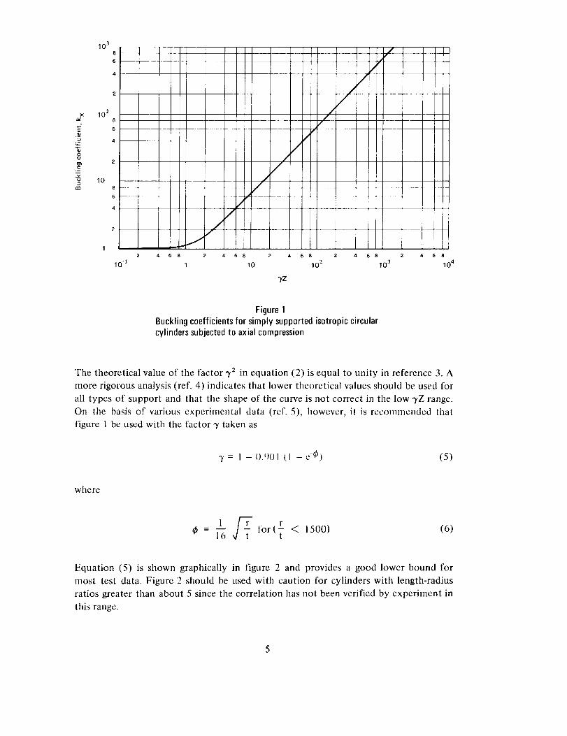
4.2.1 Axial Compression
Buckling and collapse coincide for the isotropic circular cylinder in axial compression.
From reference 3, an approximate buckling equation for supported cylinders under
axial compression is
2n I)
Nx = kx _2 (1)
where
k x m':' (1 + _32)2 "1- 12 "_2Z2= -- (2)/./.4
I112 (] "t- _2) 2
and the factor ,yz has been inserted in the second term to correct the disparity between
theory and experiment. Minimization of the equation with respect to m and/3 results in
,the variation,= ,°f k x with _,Z shown in figure 1. For moderately long cylinders
(_tZ > v3_----_2), the buckling coefficient may be expressed approximately by the
equation
kx - 44-3 vZ (3)2
/l"
Equation (3) can be rewritten in a more familiar and useful form as the equation foraxial stress:
-yt_ t
°x x/3(I -- _/2 ) r
t= 0.67E ¥ (for p. = 0.3) (4)
.o
:=
(3
13O
10 3
I6 ...... !
, i
10 28
6 ....
4
2
108
6 .....
4
2 -- --
12 4 6
10-]
_fZ
ri
--//
/
6 8 2 4
10 2
m_
_.m
6 8
10 3
i
.__ I
i2 4 6
10 4
Figure 1Bucklingcoefficients for simply supportedisotropic circularcylinderssubjectedto axialcompression
The theoretical value of the factor 3̀2 in equation (2) is equal to unity in reference 3. A
more rigorous analysis (ref. 4) indicates that lower theoretical values should be used for
all types of support and that the shape of the curve is not correct in the low -),Z range.
On the basis of various experimental data (ref. 5), however, it is recommended that
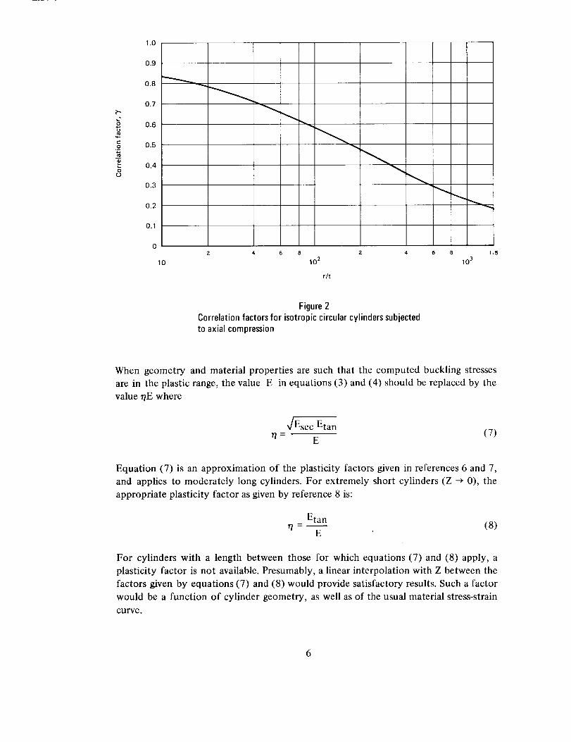
figure 1 be used with the factor 3' taken as
3' = 1 -0.¢)01 (1 -c-@) (5)
where
l _ for(r < 1500) (6)
Equation (5) is shown graphically in figure 2 and provides a good lower bound for
most test data. Figure 2 should be used with caution for cylinders with length-radius
ratios greater than about 5 since the correlation has not been verified by experiment in
this range.
5
o
c-o
o
1.0
0.9
0.8
0.7
0.6
0.5
0.4
0.3
0.2
0.1
0
10
4 6 8 2 4
10 2
r/t
1.5
10 3
Figure 2Correlation factorsfor isotropiccircular cylinderssubjectedto axial compression
When geometry and material properties are such that the computed buckling stresses
are in the plastic range, the value E in equations (3) and (4) should be replaced by the
value rtE where
_/Esec Etan7/= E
(7)
Equation (7) is an approximation of the plasticity factors given in references 6 and 7,
and applies to moderately long cylinders. For extremely short cylinders (Z _ 0), the
appropriate plasticity factor as given by reference 8 is:
Etan- (8)
E
For cylinders with a length between those for which equations (7) and (8) apply, a
plasticity factor is not available. Presumably, a linear interpolation with Z between the
factors given by equations (7) and (8) would provide satisfactory results. Such a factor
would be a function of cylinder geometry, as well as of the usual material stress-strain
curve.
6
4.2.2 Bending
Buckling and collapse coincide for isotropic, unpressurized circular cylinders in
bending. The procedures given for isotropic cylinders in axial compression may be used
also to obtain the critical maximum stress for isotropic cylinders in bending, except
that a correlation factor based on bending tests should be used in place of the factor
given by equation (5) for cylinders in axial compression. The correlation factor for the
cylinder in bending is taken on the basis of reference 9 as
3' = I - 0.731 (1 - e,4_) (9)
where
(lo)
Equation (9) is presented graphically in figure 3. This equation should be used withr
caution for T > 1500 because experimental data are not available in this range.Although the theoretical critical stress for axial compression and that for bending are
the same, the correlation factor for bending is greater than that for compression. This
g
o¢3
1.0
0.9
0.8
0.7
0.6
0.5
0.4
0.3
0.2
0.1
2
I0 j
4 6 8 2 4
10 2
r/t
8
10 3
1.5
Figure 3
Correlation factors for isotropic circular cylinders subjected
to bending
is primarily because the buckling of a cylinder in compression can be triggered by any
imperfection on the shell surface, whereas in bending, buckling is generally initiated in
the region of the greatest compressive stress.
4.2.3 External Pressure
The term "lateral pressure" designates an external pressure which acts only on the
curved walls of the cylinder and not on the ends. The load in the cylinder wall is given
by
Ny = Oyt = pr (ll)
The term "hydrostatic pressure" designates an external pressure which acts on both the
curved walls and the ends of the cylinder. The cylinder wall loads are given by
Ny=ayt = pr (12a)
Nx = °x t = pr (12b)2
Except for unusually short cylinders, the critical pressures for the two types of loads
are not significantly different.
An approximate buckling equation for supported cylinders loaded by lateral pressure is
given by reference 3 as
_r2D
Ny = ky _2 (13)
where
= Pr______2=l [ 12 3"2Z2 ]ky lr2D /32 (l +/32) 2 + rr4 (1 +/32) 2(14)
The buckling equation for cylinders loaded by hydrostatic pressure is obtained by
replacing ky by k p and the factor/32 before the bracketed expression in equation (14)by the factor (/3z + 1 ). The factor 3'2 has been inserted in the last term of
equation (14) as a correction for the disparity between theory and experiment.
The minimum values of ky for lateral pressure and kp for hydrostatic pressure areobtained by allowing the buckle aspect ratio/3 to vary continuously and are shown in
figure 4. The straight-line portion of the main curve (3'Z > 100) is given by the
equation (from ref. 3):
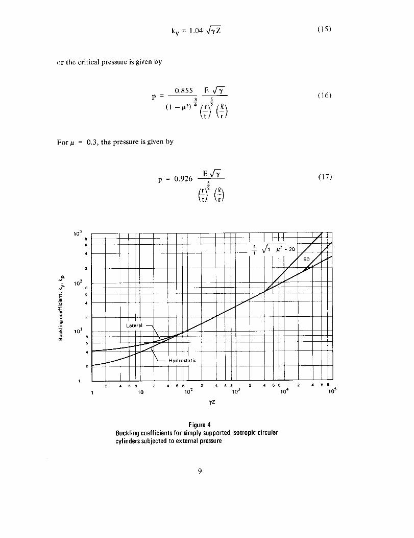
ky = J.04 _ (15)
or the critical pressure is given by
p B
o.8ss E3 5
(t)2(16)
For/a = 0.3, the pressure is given by
p = 0.926E,/V
(17)
10 3
Q.v
2_ 102
._o
101-im
2
1
4 6 e 2 4 6 e 2 4 68 2 4
10 102 103
yz
68
10 4
4 6 8
10 s
Figure 4
Buckling coefficients for simply supported isotropic circular
cylinders subjected to external pressure
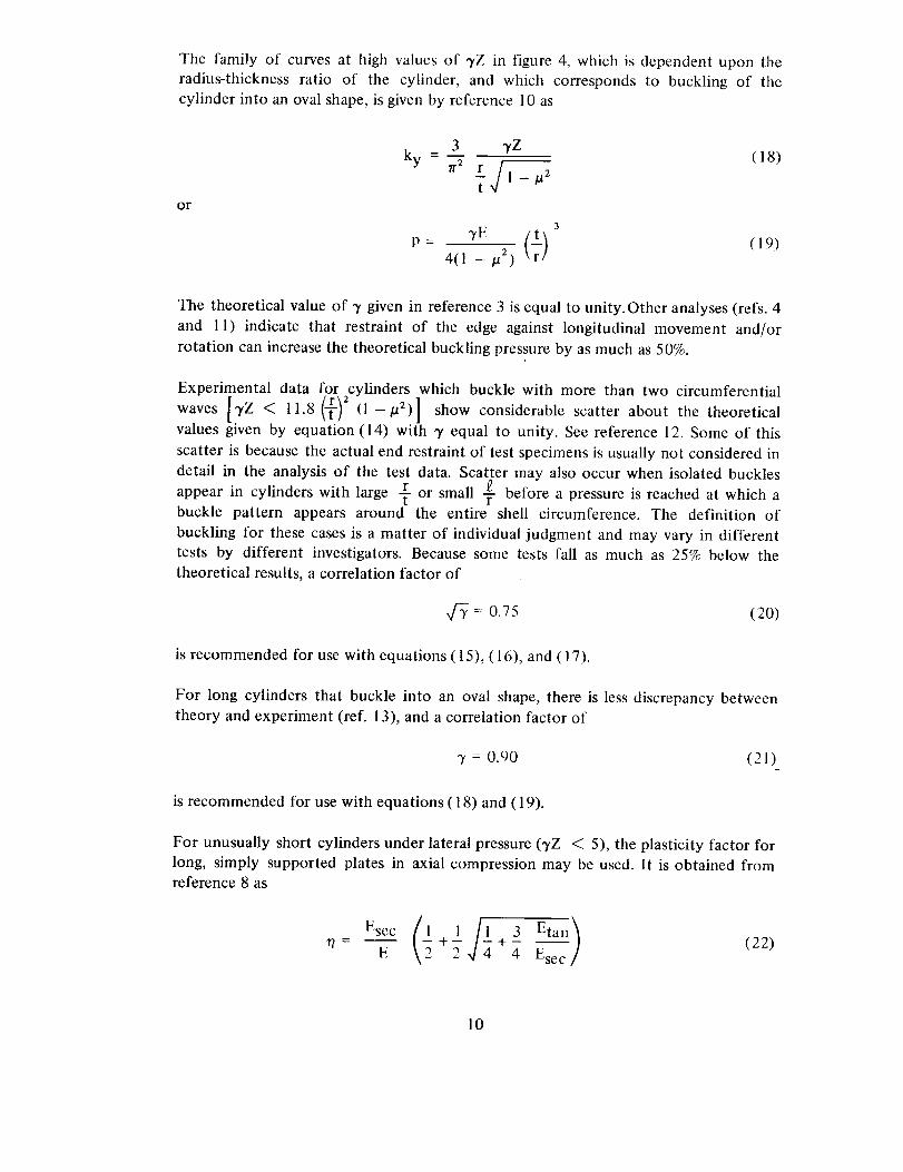
The family of curves at high values of 3"Z in figure 4, which is dependent upon the
radius-thickness ratio of the cylinder, and which corresponds to buckling of the
cylinder into an oval shape, is given by reference 10 as
or
3 3'Z= M (18)ky rr2 r f
]- _] I- /a2
P - 4(1 _ la2)(19)
The theoretical value of 3' given in reference 3 is equal to unity.Other analyses (refs. 4
and 11) indicate that restraint of the edge against longitudinal movement and/or
rotation can increase the theoretical buckling pressure by as much as 50%.
Experimental data for cylinders which buckle with more than two circumferential
•.13"Z <11.8 '"(-_)2(1 - I_2)]" show considerable scatter about the theoreticalwaves
values given by equation (14) with 3' equal to unity. See reference 12. Some of this
scatter is because the actual end restraint of test specimens is usually not considered in
detail in the analysis of the test data. Scatter may also occur when isolated buckles
r !appear in cylinders with large T or small -- before a pressure is reached at which abuckle pattern appears around the entire shell circumference. The definition of
buckling for these cases is a matter of individual judgment and may vary in different
tests by different investigators. Because some tests fall as much as 25% below the
theoretical results, a correlation factor of
,_ = 0.75 (20)
is recommended for use with equations (15), (16), and (17).
For long cylinders that buckle into an oval shape, there is less discrepancy between
theory and experiment (ref. 13), and a correlation factor of
3' = 0.90 (21)
is recommended for use with equations (18) and (19).
For unusually short cylinders under lateral pressure (3"Z < 5), the plasticity factor for
long, simply supported plates in axial compression may be used. It is obtained fromreference 8 as
ESeCE (1 _l Jl 3 Eta,E_eca)rt - +- + - (22)_ 4
10
(t)For 100 < 3,Z < ll.8 (1 - /a2), the approximate plasticity factor is obtained
from equation (12) of reference 13 as
Esec Etat 2 3 Etan (23)
r/ - E N/ \_/] t 4
and for _,Z > 11.8 (1 -/a z), the approximate plasticity factor is obtained from
equation (59) of reference 7 as
Esec (1 3 Etan (241'7 = --U- +5
No plasticity factor is available for the range 5 < Y Z < 100; satisfactory results may,
however, be achieved by linear interpolation with the parameter Z between the values
oft given by equations (22) and (23).
Plasticity factors for the biaxial stress state of hydrostatic pressure are unavailable. For
lack of better information, the plasticity factors given by equations (22) and (24) may
be used.
4.2.4 Torsion
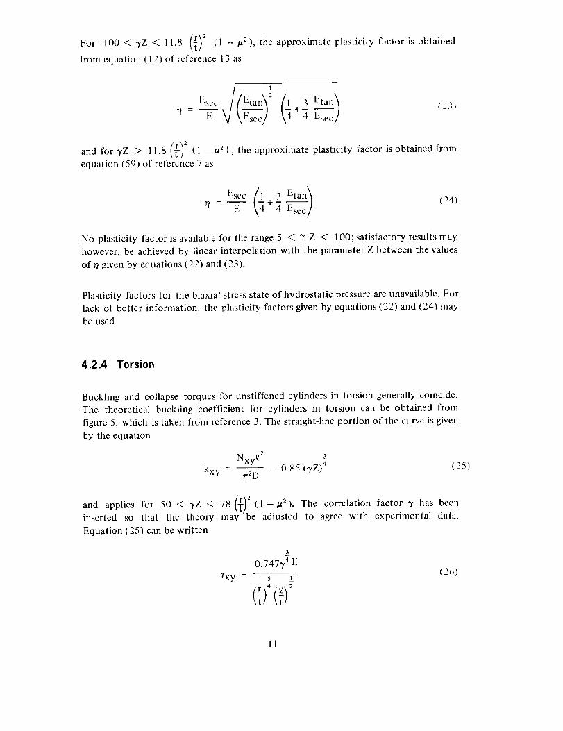
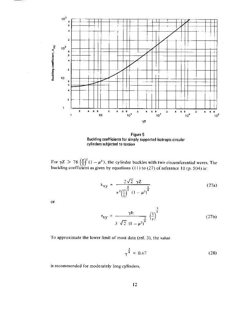
Buckling and collapse torques for unstiffened cylinders in torsion generally coincide.
The theoretical buckling coefficient for cylinders in torsion can be obtained from
figure 5, which is taken from reference 3. The straight-line portion of the curve is given
by the equation
Nxy_ 2 _3- - 0.85 (TZ) 4
kxy _.2D(25)
and applies for 50 < 7Z < 78 (1-ta 2).
inserted so that the theory may be adjusted
Equation (25) can be written
The correlation factor y has been
to agree with experimental data.
rxy
3
0.747y 4 E
s 1(26)
11
x
e-
10 .3
8
6
4
2
10 28
4
2
108
4
Z
12
1
.J
/I
//
/i
/
4 6 8 2 4 6 8 2 4 6 8 2 4
10 10 2 10 3
,yz
//
6 8
10 4
4 6 8
10 s
Figure5Bucklingcoefficientsfor simplysupportedisotropic circularcylinderssubjectedto torsion
_T_ 2For 3'Z > 78 (1 -- #2), the cylinder buckles with two circumferential waves. The
buckling coefficient as given by equations (11) to (27) of reference 10 (p. 504) is:
or
245- vzkxy = __ 1_ (27a)
7T2(t)2 (1--/.re) 4
3
rxY = 3 (27b)
3 _ (I --/a2) 4
To approximate the lower limit of most data (ref. 3), the value
3
7 4 = 0.67 (28)
is recommended for moderately long cylinders.
12
Plasticitymaybe takeninto accountby applyingtheplasticity factor from reference13in theaboveequations:
Esec (29)r_-- E
The quantity Ese c is obtained from a uniaxial stress-strain curve at a normal stress
equal to twice the critical shear stress. Equation (29) applies to cylinders of all lengths.
4.2.5 Combined Loads
Load combinations usually encountered in practice are treated here. Generally, the
recommended practice for handling combinations of two or more load conditions that
may cause buckling is that the sum of the various critical load ratios is equal to unity.
4.2.5.1 Circular Cylinders in Axial Compression and Bending
The recommended interaction equation for combined compressive load and bending is
Rc + Rb = 1 (30)
The quantities Rc and Rb are, respectively, the compressive and bending load or stress
ratios. The denominators of the ratios are the allowable loads or stresses given by
equations (4) to (6) for cylinders in axial compression and by equations (4) and (9) for
cylinders in bending.
4.2.5.2 Circular Cylinders in Axial Compression and External Pressure
The recommended interaction equation for combined compressive load and
hydrostatic pressure or lateral pressure is
Rc + Rp = ! (31)
The quantities R c and Rp are, respectively, the compressive and hydrostatic- orlateral-pressure load or stress ratios. The denominators of the ratios are the allowable
stresses given by equations (4) to (6) for cylinders in axial compression and by
equations (16) and (20) for cylinders subjected to external pressure.
13
4.2.5.3 Circular Cylinders in Axial Compression and Torsion
For cylindrical shells under torsion and axial compression, the analytical interaction
curve is a function of Z, and varies from a parabolic shape at low-Z values to a straight
line at high-Z values. The scatter of experimental data suggests the use of a straight-line
interaction formula. Therefore, the recommended interaction equation is
Rc + Rt = 1 (32)
The quantities Rc and R t are, respectively, the compressive and torsion load or stressratios. The denominators of the ratios are the allowable stresses given by equations (4)
to (6) for cylinders in axial compression and by equations (26) and (28) for cylinders
in torsion.
4.2.5.4 Internally Pressurized Circular Cylinders in Axial Compression
Buckling and collapse coincide for internally pressurized circular cylinders in axial
compression as in the case of the unpressurized cylinder. Pressurization increases the
buckling load in the following ways:
,
.
The total compressive load must be greater than the tensite pressurization
load pTrr2 before buckling can occur.
The destabilizing effect of initial imperfections is reduced. The
circumferential tensile stress induced by the pressurization inhibits the
diamond buckling pattern, and, at sufficiently high pressurization, the
cylinder buckles in the classical axisymmetric mode at approximately the
classical buckling stress.
Lower bound curves giving the increase in buckling load as a function of pressure,
based on results for Mylar cylinders, are given in reference 14 for various
radius-to-thickness ratios. Because these curves are unsubstantiated at present for other
materials, the more conservative values given in reference 15 are recommended for
design use. It is therefore recommended that the total load for buckling, unless
substantiated by test, be obtained by the addition of the pressurization load prrr 2 , the
buckling load for the unpressurized cylinder [eqs. (4) and (5)], and an increase in the
buckling load caused by pressurization; that is
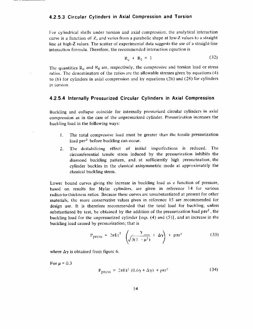
where A_/is obtained from figure 6.
For ta = 0.3
Pprcss = 2nEt2 (0.63' + AT) + pnr 2 (34)
14
<3
10
10-1
10-2
8
6
J2
10-2
Jf
J
JI--
4 6 8 2 4 6 8 2
10 "1 1
P- [ rl2E t
6 8
10
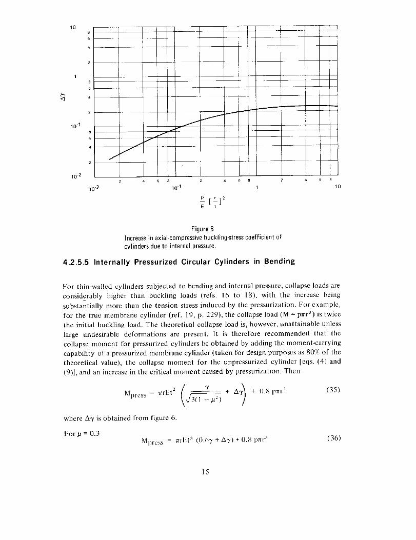
Figure 6Increasein axial-compressivebuckling-stresscoefficient ofcylinders due to internal pressure.
4.2.5.5 Internally Pressurized Circular Cylinders in Bending
For thin-walled cylinders subjected to bending and internal pressure, collapse loads are
considerably higher than buckling loads (refs. 16 to 18), with the increase being
substantially more than the tension stress induced by the pressurization. For example,
for the true membrane cylinder (ref. 19, p. 229), the collapse load (M = prrr 3) is twice
the initial buckling load. The theoretical collapse load is, however, unattainable unless
large undesirable deformations are present. It is therefore recommended that the
collapse moment for pressurized cylinders be obtained by adding the moment-carrying
capability of a pressurized membrane cylinder (taken for design purposes as 80% of the
theoretical value), the collapse moment for the unpressurized cylinder [eqs. (4) and
(9)1, and an increase in the critical moment caused by pressurization. Then
Y + AT) + 0.8 prrr' (35)Mpress = rrrEt2 -,/_3(1 -/a 2)
where A7 is obtained from figure 6.
For/a = 0.3
Mpres s = nrl{t 3 (0.67+A7)+0.8 pnr 3 (36)
15
42.5.6 Internally Pressurized Cylinders in Axial Compression and Bending
For internally pressurized circular cylinders in combined axial compression and
bending, equation (30) is recommended for use in combination with equations (33)
or (34) and (35) or (36).
4.30rthotropic Cylinders
The term "orthotropic cylinders" covers a wide variety of cylinders. In its strictest
sense, it denotes cylinders made of a single orthotropic material or of orthotropic
layers. It also denotes types of stiffened cylinders for which the stiffener spacing is
small enough for the cylinder to be approximated by a fictitious sheet whose
orthotropic bending and extensional properties include those of the individual
stiffening elements averaged out over representative widths or areas. Generally, the
directions of the axes of orthotropy are taken to coincide with the longitudinal and
circumferential directions of the cylinder.
The behavior of the various types of orthotropic cylinders may be described by a single
theory, the elements of which are equations of equilibrium for the buckled structure,
relationships between force and moment resultants, and extensional and bending
strains. For cylinders of a single orthotropic material, it is generally permissible to
neglect coupling between force resultants and bending strains, and between moment
resultants and extensional strains. The theory is then similar to that for isotropic
cylinders. For stiffened cylinders or for cylinders having orthotropic layers, however,
the neglect of the coupling terms can lead to serious errors. For example, the inclusion
of coupling terms yields a significant difference in theoretical results for stiffened
cylinder configurations having stiffeners on the inner surface or on the outer surface.
The difference vanishes when coupling is omitted.
Theoretical and experimental results for stiffened shells are generally in better
agreement than those for unstiffened shells. The possibility of local buckling of the
cylinder between stiffening elements should be checked.
4.3.1 Axial Compression
A buckling equation for stiffened orthotropic cylinders in compression (ref. 20) is
given by:
A12 AI3
A:z A_3
A32 A33for (n >_ 4) (37)
16
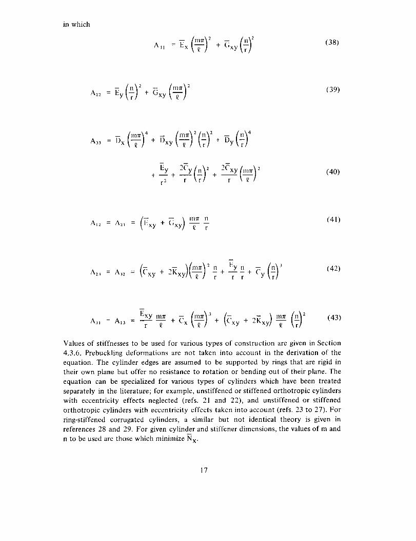
in which
All(38)
= - (39)
+--+ +
r2 r _ r_ r \ _ /
(40)
(_ ) mTr n (41)A12 = A21 = xy + Gxy _ r
2'2+___+?A23 = A32 = xy + 2Kxy r r r Y
(42)
Values of stiffnesses to be used for various types of construction are given in Section
4.3.6. Prebuckling deformations are not taken into account in the derivation of the
equation. The cylinder edges are assumed to be supported by rings that are rigid in
their own plane but offer no resistance to rotation or bending out of their plane. The
equation can be specialized for various types of cylinders which have been treated
separately in the literature; for example, unstiffened or stiffened orthotropic cylinders
with eccentricity effects neglected (refs. 21 and 22), and unstiffened or stiffened
orthotropic cylinders with eccentricity effects taken into account (refs. 23 to 27). For
ring-stiffened corrugated cylinders, a similar but not identical theory is given in
references 28 and 29. For given cylinder and stiffener dimensions, the values of m and
n to be used are those which minimize N x.
17

The unusuallylargenumberof parametersin equation(37) doesnot permit anydefinitive numerical results to be shown. For combinationsof parametersrepresentativeof stiffenedshells,calculationsindicatethatexternalstiffening,whetherstringersor rings,or both, can be moreeffectivethan internal stiffeningfor axialcompression. Generally, calculations neglecting stiffener eccentricity yieldunconservativevaluesof the buckling load of internally stiffenedcylindersandconservativevaluesof the bucklingloadof externallystiffenedcylinders(ref. 23).Anextensiveinvestigationof the variationof the bucklingload with variousstiffenerparametersis reportedin reference25.The limitedexperimentaldata(refs.28 to 35)for stiffenedshellsarein reasonablygoodagreementwith thetheoreticalresultsfor therangeof parametersinvestigated.
On the basisof availabledata,it is recommendedthat the bucklingloadsof cylinderswith closelyspaced,moderatelylargestiffenerscalculatedfrom equation(37) bemultiplied by a factor of 0.75. Correlationcoefficientscoveringthetransitionfromunstiffenedcylindersto stiffenedcylinderswith closelyspacedstiffenershavenot beenfully investigated.Whiletheoryandexperiment(ref. 34)indicatethatrestraintagainstedgerotation andlongitudinalmovementsignificantlyincreasesthebucklingload,notenoughis known about the edgerestraint of actual cylindersto warrant takingadvantageof theseeffectsunlesssubstantiatedby tests.
For layeredor unstiffenedorthotropic cylindricalshells,the availabletestdataarequite meager(refs.36 and37). For configurationswherethecouplingcoefficientsCx,Cy, Cxy, and Kxy canbe neglected,it is recommendedthat the bucklingload becalculatedfrom theequation
Nx _2 Q 1-3xy/32 Dy )-- 1112 + 3 _ + =
rr2_x " Dx Dx
+y2_4 ExEy_ l-_xy
7r4m2 Dx r t x t Exy fl2 (44)Ex + - 2Ex + Ey/34
The correlation factor 3' is taken to be of the same form as the correlation factor for
isotropic cylinders [eq. (5)] with the thickness replaced by the geometric mean of the
radii of gyration for the axial and circumferential directions. Thus
7 = 1-0.901 (1 -e-b) (45)
where
18
[ ]1 r 7
4.3.2 Bending
Theoretical and experimental results (refs. 24, 29, and 38 to 40) indicate that tile
critical maximum load per unit circumference of a stiffened cylinder in bending can
exceed the critical unit load in axial compression. In the absence of an extensive
investigation, it is recommended that the critical maximum load per unit circumference
of a cylinder with closely spaced stiffeners be taken as equal to the critical load in axial
compression, which is calculated from equation (37) multiplied by a factor of 0.75.
For layered or unstiffened orthotropic cylinders with negligible coupling coefficients,
it is recommended that the maximum unit load be calculated by means of
equation (44) with 3' replaced by
3' = 1 --0.731 (1 --e-0) (47)
where
1 r 5-
0 = 2').8 (48)
4.3.3 External Pressure
The counterpart of equation (37) for stiffened orthotropic cylinders under lateral
pressure is given by
r
112
All A12 AI3
A21 A22 A23
A31 A3a A33
(49)
19
For hydrostatic pressure, the quantity n 2 shown in equation (49) is replaced by
n2+_ -
In the case of lateral pressure, m is equal to unity while n must be varied to yield a
minimum value of the critical pressure, but is not less than 2. In the case of hydrostatic
pressure, the value of m should be varied as well as n. For long cylinders, equation (49)
is replaced by
p = r3 (50)
If the coupling coefficients Cx, Cy, Cxy, and K-xy can be neglected, the critical
buckling pressure can be approximated by (ref. 22):
1
[5 • 513 .Dy (_xEy-- _
P _ ---2-- _y (51)_r 2
for
±3 2
(_y_7 (_x_y--_y._ _2
\Dx/ \ i5 } T > 5oo (52)
Equation (49) has been investigated primarily for isotropic cylinders with ring
stiffeners (refs. 41 to 43). For closely spaced ring stiffening, references 41 and 42 show
that the effectiveness of inside or outside rings depends on the shell and ring
geometries. Generally, for shells with values of Z less than 100, outside rings are more
effective than inside rings, while for values of Z greater than 500, the reverse is true. As
the ring geometry varies, the effectiveness of outside stiffening tends to increase as the
stiffness of the rings relative to the shell increases. Somewhat lower buckling pressures
are given by the extremely complex but more accurate theory of reference 44, but the
differences are not so significant as to warrant its use.
The experimental results for ring-stiffened cylinders described in reference 45 are in
reasonably good agreement with the theoretical results of equation (49). For cylinders
of all types, it is recommended that the buckling pressure calculated from
equation (49) be multiplied by a factor of 0.75 for use in design, as has been
recommended for unstiffened isotropic cylinders of moderate length.
20
4.3.4 Torsion
The problem of torsional buckling of orthotropic cylinders has been treated in
references 22 and 46, which do not take coupling between bending and extension into
account, and in reference 47, which does. If coupling effects are negligible, the critical
torque of moderately long cylinders can be estimated from the relationship (ref. 22):
3
5 ExEy __ Ex RzMt _ _ 1.75 Dy -_- ---T (53)
\ Ey / _T
for
5 i
-/,\r E- -_ 7Oy( _2;7 g-J (54)
Reference 47, however, shows that coupling effects are quite important for cylinders
stiffened by closely spaced rings. For long shells, internal rings are generally more
effective than outside rings; for short shells, the reverse is true. In the absence of
general formulas or graphs to cover the entire range of parameters that should be
considered, the equations of reference 47 should be solved for each specific caseconsidered.
The test data of reference 48 are in good agreement with theoretical predictions but
are insufficient to provide an adequate test of the theory. It is therefore recommended
that theoretical critical torques be multiplied by a factor of 0.67 for moderately long
cylinders.
4.3.5 Combined Bending and Axial Compression
On the basis of theory (refs. 24, 29, and 38) and limited experimental data (refs. 28
and 29), a straight-line interaction curve is recommended for orthotropic cylinders
subjected to combined bending and axial compression. The critical combinations of
loading are thus given by
Rc + Rb = 1 (55)
21
4.3.6 Elastic Constants
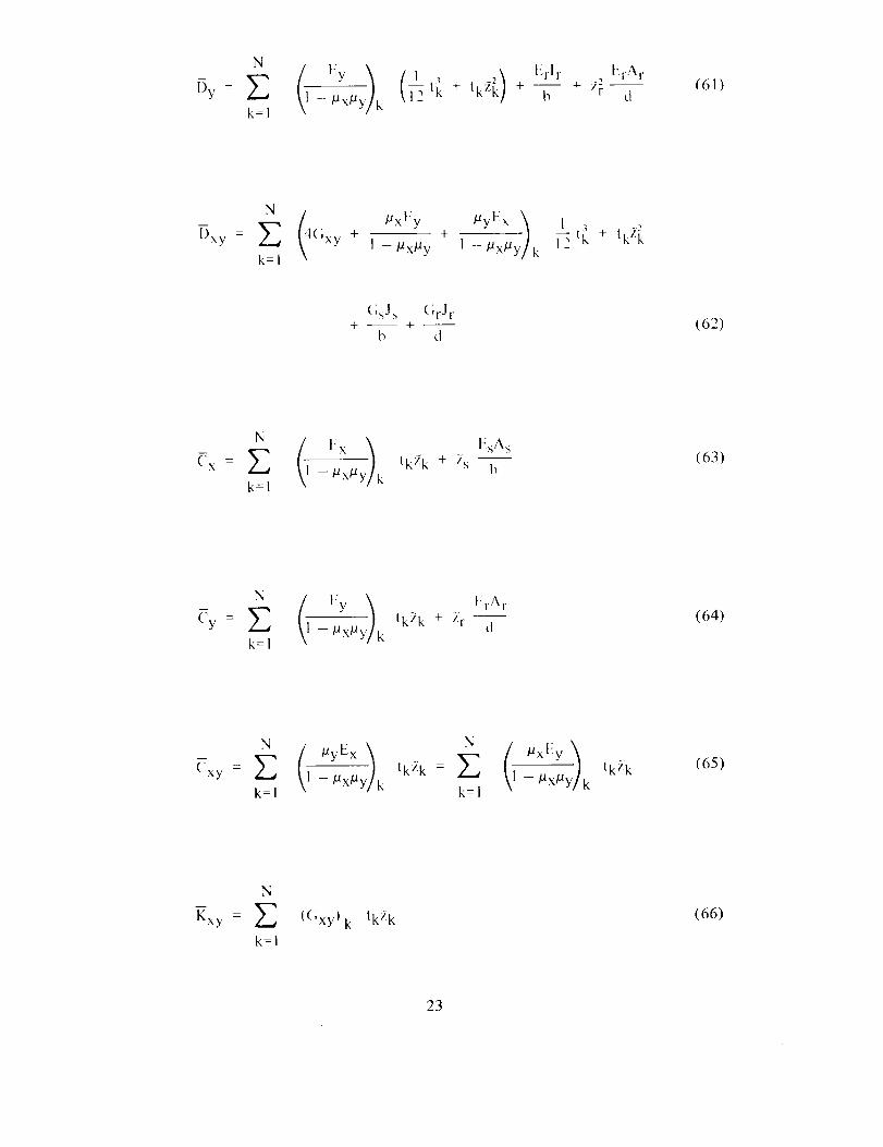
The values of the various elastic constants used in the theory of buckling of
orthotropic cylinders are different for different types of construction.
4.3.6.1 Stiffened Multilayered Orthotropic Cylinders
Some widely used expressions for this type of cylinder are:
N (] Ex t EsAs= t k + --
Ex Z --- _xtty k bk=l
(56)
N t Ey ;) ErA r= t k +EY Y]_ 1-Tx_U k d
k=l
(57)
Exy = _ 1 - ttx/aY/k tk = Z 1 -/ax/aY/kk--1 k=l
tk (58)
N
C,,xy = _-"]_ (GxY)k tk
k=l
(59)
l-)x = Z 1 -/ax/a kk=l
(1 ) Esls EsAst]_ + tk2 _. +--_ + 2_- b (60)
22
= + tkZ_ +k=l
t{r A r
+ zi_ d(61)
N (4 pxI'IY /lyEx _= +
Dxy E (;xy + 1 -/Xx/ay 1 - px,UY/kk=l
{;sJs (;rJr
b d(62)
(_ l_x EsAs= tkZk + '_s b
k=l
(63)
N ( l,ly 1 l!rAr= tk2 k + Zr
CY _ 1 --tlx/Xy k dk=l
(64)
= lk/, k = tk_ k(=xy I - #x#Y/k 1 - #x#y/k
k=l -=
(65)
N
Kxy = _ {(;xylk tk:_k
k=l
(66)
23
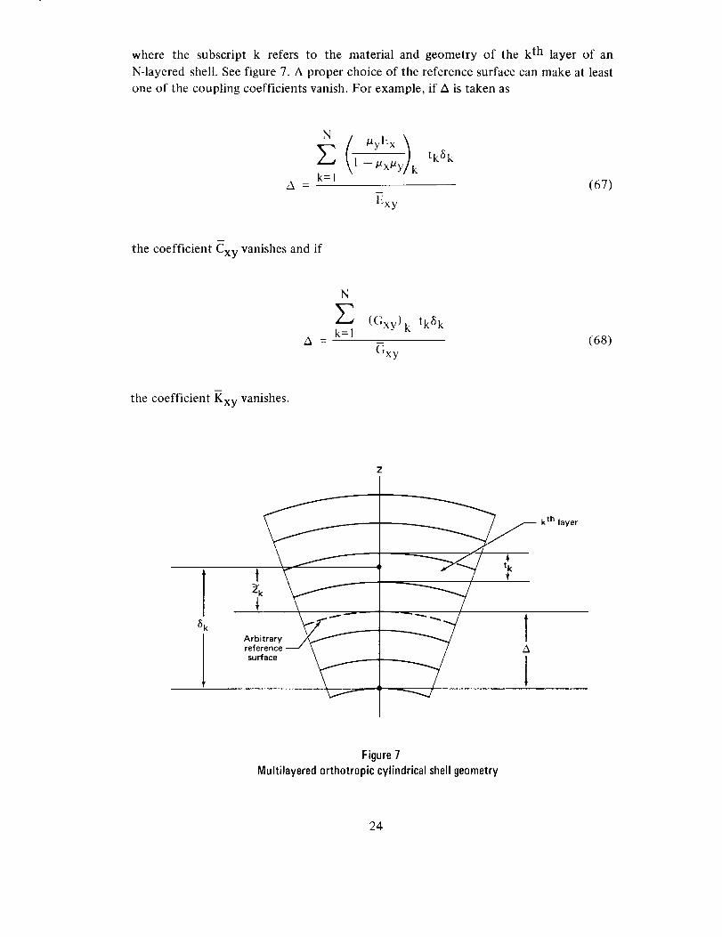
where the subscript k refers to the material and geometry of the k th layer of an
N-layered shell. See figure 7. A proper choice of the reference surface can make at least
one of the coupling coefficients vanish. For example, if A is taken as
1-.x.y/k tk6k
k=lA = (67)
Exy
the coefficient Cxy vanishes and if
N
Z ((;xv) tk6 kk=l - k
A = (68)Gxy
the coefficient Kxy vanishes.
_k
t
surface
k th layer
Figure7Multilayeredorthotropic cylindricalshellgeometry
24

4.3.6.2 Isotropic Cylinders with Stiffeners and Rings
For a cylinder consisting of a stiffened single isotropic layer and for a reference surface
at the center of the layer, equations (56) to (66) reduce to
Et EsA sEx - + (69)
1 -/a 2 b
Et ErAr
EY - 1 - _2 + t----i--- (70)
_Et
E×y - (71)
Et
C'xy = -q(1 +/a) (72)
Et 3 Esl s EsAs
12(1 t*:) b b(73)
Et 3 Erlr ErAr
Dy - +--+ 2"_-12(1 _2) d d
(74)
Et 3 GsJ s GrJr- +-- 4 --
Dxy 6(1 + tt) b d(75)
EsAsCx = Z's (76)
b
ErAr(:y = z r -- (77)
d
m
Cxy = Kxy = 0 (78)
25
4.3.6.3 Ring-Stiffened Corrugated Cylinders
The following formulas are commonly used to calculate the required stiffnesses of
ring-stiffened corrugated cylinders, with the choice of formula depending on the
different assumptions which may be made'
Er ArEx = Et Ey - (79)' d
C,xy = (;t (t) (80)
[)x = E/ (81)
I'_rlr ErA r
By - d + 4 (82)
GrJrDxy - d (83)
ErAr
_y = _r d (84)
Exy = _x = (--:xy = Kxy = 0 (85)
Slightly different stiffnesses are given in reference 39.
4.3.6.4 Waffle-Stiffened Cylinders
Stiffnesses for cylinders with waffle-like walls are described in references 49 to 5 I.
4.3.6.5 Special Considerations
In some designs of stiffened cylinders, the skin may buckle before failure of the
cylinder. Buckled sheet is less stiff than unbuckled sheet. The decreased stiffness can
be calculated by methods similar to those presented in references 31,40, and 52.
26
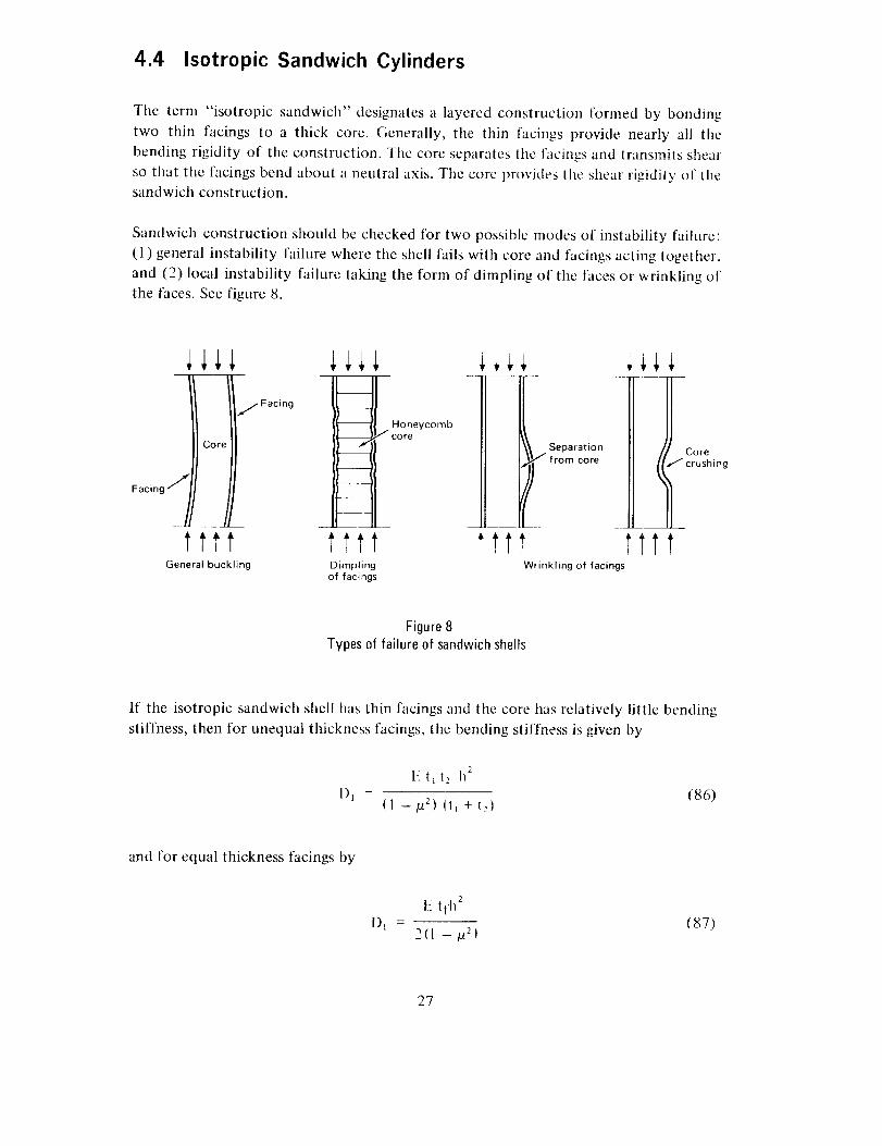
4.4 Isotropic Sandwich Cylinders
The term "isotropic sandwich" designates a layered construction formed by bonding
two thin facings to a thick core. Generally, the thin facings provide nearly all the
bending rigidity of the constrtlction. _llle core separates tile facings and transmits shear
so that tile facings bend about a neutral axis. The core provides tile shear rigidity of the
sandwich construction.
Sandwich construction should be checked for two possible modes of instability failure:
(1) general instability failure where the shell fails with core and facings acting together,
and (2) local instability failure taking the form of dimpling of tile faces or wrinkling of
the faces. See figure 8.
/ 1 j//FacingCore
ttttGeneral buckling
iii+
__ _core
ttttDimpling
of facings
_.,,. Separatio n
from core Cr°rSh i n g
ttt l!t?Wrinkling of facings
Figure 8
Types of failure of sandwich shells
If tile isotropic sandwich shell has thin facings and tile core has relatively little bending
stiffness, then for unequal thickness facings, the bending stiffness is given by
1'_t_ t2 h _
I)_ = (86)(1 -/fi) (t, +re)
and for equal thickness facings by
1)1t_2tfh 2
w
2{I -/a 2 )(87)
27
The extensional stiffness for unequal thickness facings is given by
EB_ - (t_ + t2)
( I -/a 2)(88)
and for equal thickness
2E tfBt -
(1 -/Z}
The transverse shear stiffness for an isotropic core is given by
I12
Dq = Gxz t_ + t2tl
2
and for equal thickness by
(89)
(90)
]12
Dq = Gxz h-tf (90a)
The stiffness of other types of sandwich construction are given in references 53, 54,and 55.
4.4.1 Axial Compression
Investigations of buckling behavior of isotropic sandwich circular cylinders in axial
compression are reported in references 21 and 56. Design information from these
references is given in figures 9 and 10.
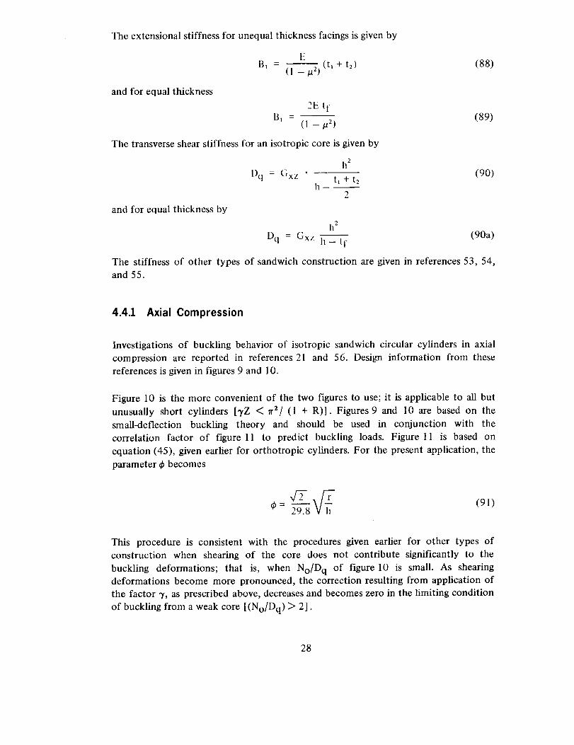
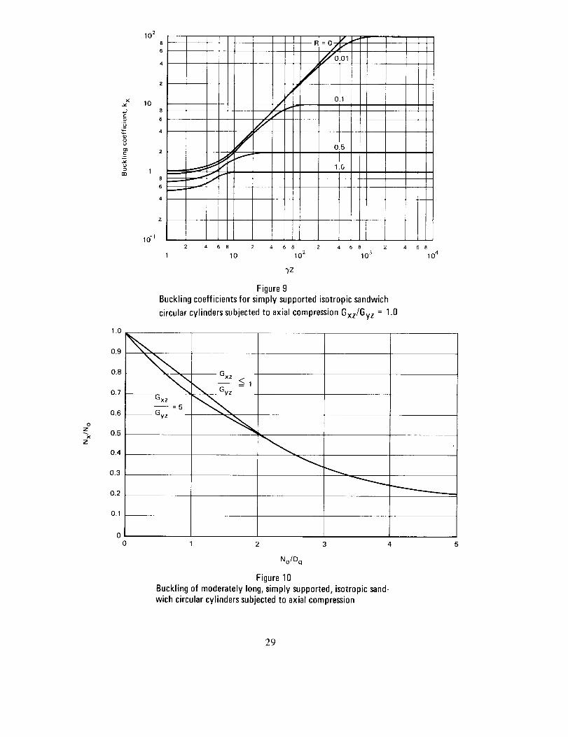
Figure 10 is the more convenient of the two figures to use; it is applicable to all but
unusually short cylinders [,yZ < 7r2/ (1 + R)]. Figures 9 and 10 are based on the
small-deflection buckling theory and should be used in conjunction with the
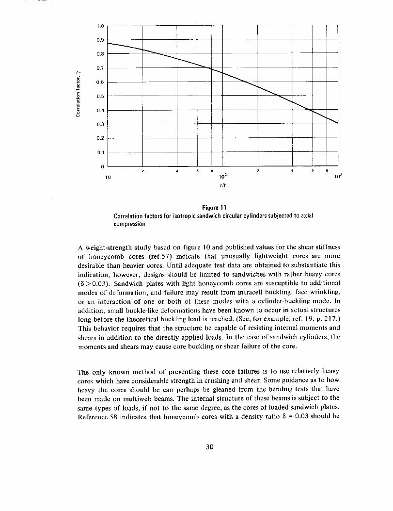
correlation factor of figure 11 to predict buckling loads. Figure 11 is based on
equation (45), given earlier for orthotropic cylinders. For the present application, the
parameter _ becomes
_ (91)_b- 29.8
This procedure is consistent with the procedures given earlier for other types of
construction when shearing of the core does not contribute significantly to the
buckling deformations; that is, when No/D q of figure 10 is small. As shearingdeformations become more pronounced, the correction resulting from application of
the factor 7, as prescribed above, decreases and becomes zero in the limiting condition
of buckling from a weak core [(No/Dq) > 2].
28
8
03
1.0
10 2
8
6
4
2
108
6
4
2
18
6
4
2
lO-_
iI
/J
"L,f
/ :Ol/
C.1
0,5
1,0
i
2 4 6 8 2 4 6 8 2 4 6 2
1 10 10 2 10 3
?Z
Figure 9Buckling coefficientsfor simplysupportedisotropic sandwich
circularcylinderssubjectedto axialcompressionGxz/Gyz = 1.0
6 8
10 4
0Z
x
z
0.9
0.8
0.7
0.6
0.5
0,4
0.3
0.2
0.1
GXZ
No/Dq
Figure 10Bucklingof moderatelylong,simplysupported,isotropicsand-wichcircularcylinderssubjectedto axialcompression
29
o
O¢.9
1.0
0.9
0.8
0.7
0.6
0.5
0.4
0.3
0.2
0.1
0
10
2 4 6 8
10 2
rlh
2 4 6 8
10 3
Figure 11Correlation factors for isotropic sandwichcircularcylinderssubjectedto axialcompression
A weight-strength study based on figure 10 and published values for the shear stiffness
of honeycomb cores (ref.57) indicate that unusually lightweight cores are more
desirable than heavier cores. Until adequate test data are obtained to substantiate this
indication, however, designs should be limited to sandwiches with rather heavy cores
(6 > 0.03). Sandwich plates with light honeycomb cores are susceptible to additional
modes of deformation, and failure may result from intracell buckling, face wrinkling,
or an interaction of one or both of these modes with a cylinder-buckling mode. In
addition, small buckle-like deformations have been known to occur in actual structures
long before the theoretical buckling load is reached. (See, for example, ref. 19, p. 217.)
This behavior requires that the structure be capable of resisting internal moments and
shears in addition to the directly applied loads. In the case of sandwich cylinders, the
moments and shears may cause core buckling or shear failure of the core.
The only known method of preventing these core failures is to use relatively heavy
cores which have considerable strength in crushing and shear. Some guidance as to how
heavy the cores should be can perhaps be gleaned from the bending tests that havebeen made on multiweb beams. The internal structure of these beams is subject to the
same types of loads, if not to the same degree, as the cores of loaded sandwich plates.
Reference 58 indicates that honeycomb cores with a density ratio _ = 0.03 should be
30
adequateto preventcorefailure.Largemarginsagainstfailurein intracellbucklingandwrinkling canbe obtainedwith ratherheavycores(6< 0.03)with little or no weightpenalty.Moreover,whenheavycoresareused,approximateequationsareadequateforpredictingfailuresin the intracell bucklingandfacewrinklingmodes.Thefollowingequationsmaybeusedfor thispurpose.For intracellbuckling(refs.55and59):
o x _.5 E R . (92)
where S is the core cell size expressed as the diameter of the largest inscribed circle and
4E Eta n
where E and Eta n are the elastic and tangent moduli of the face-sheet material. If
initial dimpling is to be checked, the equation
o x = 2.2 E R (94)
should be used. The sandwich will still carry load if initial dimpling occurs. Critical
wrinkling stresses are predicted by references 19 (p. 341) and 55.
l
o x = 0.50 EsecEzGxz (95)
where E z is the modulus of the core in a direction perpendicular to the core and Gxz is
the shear modulus of the core in the x-z plane. If biaxial compressive stresses are
applied to the sandwich, then the coefficients of the equations must be reduced by the1
factor (1 + f3)-7 (ref. 60) where
minimunl principal compressive stress in facimzsf = _ (96)
nmxinmm principal compressive stress in facings
Wrinkling and intracell buckling equations which consider strength of bond, strength of
foundation, and initial waviness of the facings are given in references 55, 61, and 62.
The plasticity correction factor given by equations (7) and (8) for isotropic cylinders in
axial compression also may be applied to isotropic sandwich cylinders. The factor is
applicable to sandwich cylinders with stiff cores and becomes somewhat conservative
as the shear stiffness of the core is decreased (ref. 58).
31

4.4.2 Bending
The buckling equations given in Section4.2.1 for circular cylinders in axial
compression may be used for cylinders in bending, provided the correlation factor 7 is
taken from figure 12 instead of from figure 11, Figure 12 is based on equation (47),
given earlier for orthotropic cylinders in bending.
g
O
1.0
09
0.8
0.7
0.6
0.5
0.4
0.3
0
I0
2 4 6 8 Z 4
0.2
0.1
10 2
r/h
6 8
10 3
Figure 12
Correlation factors for isotropic sandwich circular cylinderssubjected to bending
4.4.3 Lateral Pressure
A plot of ky against 3,Z, constructed from the data given in reference 63, is given in
figure 13. The straight-line portion of the curve of figure 13 for a sandwich cylinder
with a rigid core (R = 0) is given by the equation
Ny,_ 2
- = 0.56 x/_ (97)ky rr2 D1
There are no experimental data to substantiate figure 13; experience with isotropic
cylinders, however, suggests that a factor 3' equal to 0.56 is to be used with this figure.
32

e-
.9
._u
m
10 2
10
1
lO-1
8
6
4 ,
2
1
J
I
J
6 8 2 4 8 2 4 6 8 2 4
10 10 2 10 3
"YZ
O.!i
1 .()
Figure 13Bucklingcoefficientsfor simplysupportedisotropicsandwich
circularcylinderssubjectedto lateral pressureGxz/Gyz = 1.0
Here, as with sandwich cylinders in axial compression or bending, designs should be
limited to sandwich cylinders for which the density ratio 5 is 0.03 or greater, unless
the design is substantiated by adequate tests.
The plasticity factors for isotropic cylinders subjected to external pressure, expressed
by equations (22), (23), and (24), may be used for isotropic sandwich cylinders
subjected to lateral pressure.
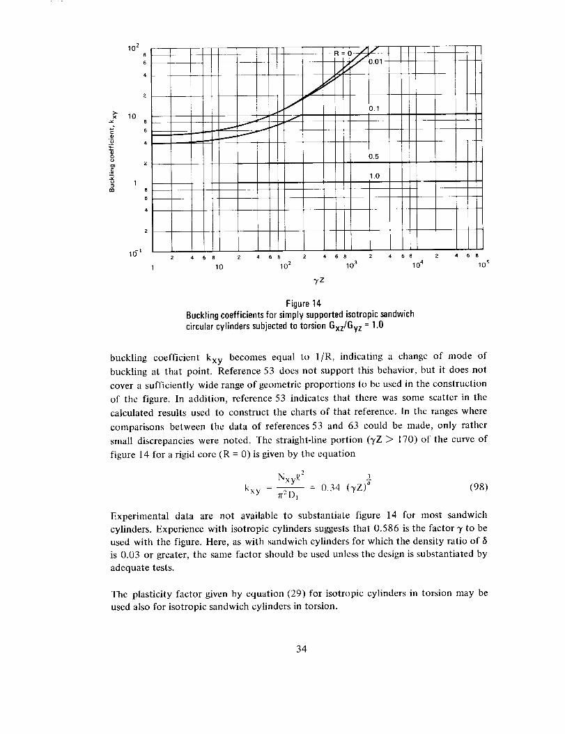
4.4.4 Torsion
Isotropic sandwich cylinders in torsion have not received the same attention as
cylinders in compression. Rigid- and weak-core cases are reasonably well defined. While
the transition region between rigid and weak cores is not as well defined, it is probably
sufficient for design purposes. Information on the transition region is given in
references 53 and 63, the latter of which was used to construct the plot of figure 14,
which applies to sandwich cylinders with cores exhibiting isotropic shear behavior
Gxz/Gy z = 1. The curves of this figure are discontinuous at the value of'rZ where the
33
._o
8
en
10 2
10
2
18
6
4
2
I
J
I
J
4 6 8
10
LL01 ....
i
I
i
).1
Ii
I0.5
11.0
2 4 6 8 2 4 6 2 4 6 8
10 2 10 3 10 4
-),Z
Figure14Buckling coefficients for simplysupportedisotropicsandwichcircularcylinderssubjectedto torsion Gxz/Gyz = 1.0
Z 4 6 8
lO s
buckling coefficient kxy becomes equal to l/R, indicating a change of mode of
buckling at that point. Reference 53 does not support this behavior, but it does not
cover a sufficiently wide range of geometric proportions to be used in the construction
of the figure. In addition, reference 53 indicates that there was some scatter in the
calculated results used to construct the charts of that reference. In the ranges where
comparisons between the data of references 53 and 63 could be made, only rather
small discrepancies were noted. The straight-line portion (TZ > 170) of the curve of
figure 14 for a rigid core (R = 0) is given by the equation
Nxy_ 2 3
kxy - n2D, - 0.34 (TZ) 4 (98)
Experimental data are not available to substantiate figure 14 for most sandwich
cylinders. Experience with isotropic cylinders suggests that 0.586 is the factor 7 to be
used with the figure. Here, as with sandwich cylinders for which the density ratio of
is 0.03 or greater, the same factor should be used unless the design is substantiated by
adequate tests.
The plasticity factor given by equation (29) for isotropic cylinders in torsion may be
used also for isotropic sandwich cylinders in torsion.
34
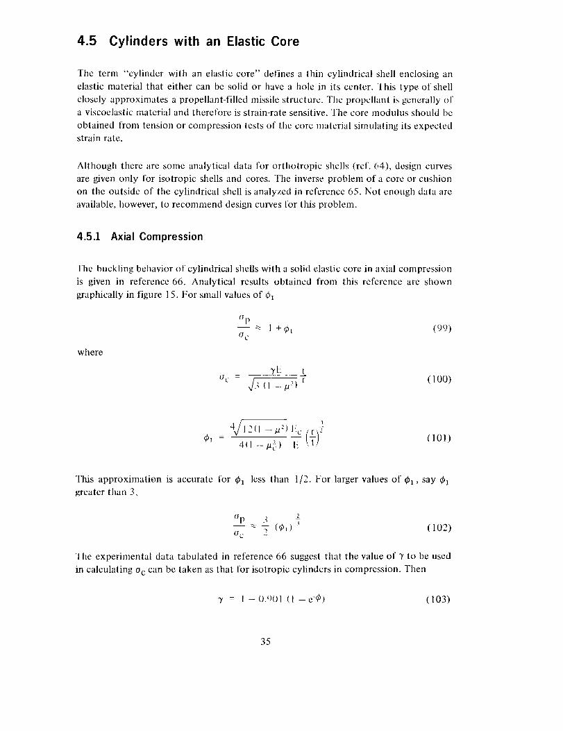
4.5 Cylinders with an Elastic Core
Tile term "cylinder with an elastic core" defines a thin cylindrical shell enclosing an
elastic material that either can be solid or have a hole in its center. This type of shell
closely approximates a propellant-filled missile structure. The propellant is generally of
a viscoelastic material and therefore is strain-rate sensitive. The core modulus should be
obtained from tension or compression tests of the core material simulating its expectedstrain rate.
Although there are some analytical data for orthotropic shells (ref. 64), design curves
are given only for isotropic shells and cores. Tile inverse problem of a core or cushion
on the outside of the cylindrical shell is analyzed in reference 65. Not enough data are
available, however, to recommend design cmwes for this problem.
4.53 Axial Compression
The buckling behavior of cylindrical shells with a solid elastic core in axial compression
is given in reference 66. Analytical results obtained from this reference are shown
graphically in figure 15. For small values of _51
CSp-- _ 1+ Ol (99)0¢
where
7E t-7 (100)
Uc = V/3 <1 _p2)
4" = 411 --/a_,) li(101)
This approximation is accurate for Ca less than t/2. For larger values of ¢1, say ¢a
greater than 3,
Op
-- -- -7 (Ol) "_ (102)0 C -
The experimental data tabulated in reference 66 suggest that the value of _' to be used
in calculating o c can be taken as that for isotropic cylinders in compression. Then
y = I -0._)01 (I -e-O) (103)
35
t
"o
O-
108
6
4
2
18
6
4
2
10-]
$
6
4
/10-2
2
10 .2
/J
/
/i
/ !
2 4 6 8 2 4 6 8 2
1 10
_-___21 Ec r 13/2
6 8
10 2
Figure15Variation of compressivebuckling stresswith corestiffnessparameter
where
I _ (104)]6,Jt
The plasticity correlation factors given by equations (7) and (8) for isotropic cylinders
in axial compression may be applied also to the cylinder with an elastic core.
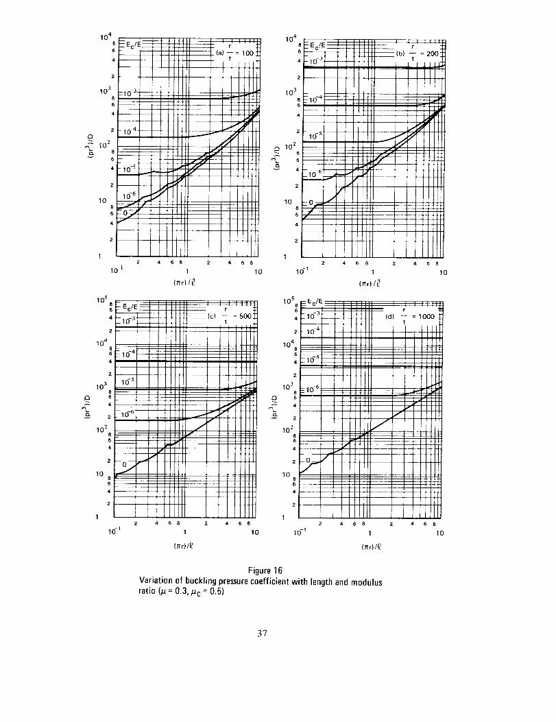
4.5.2 External Pressure
Analytical curves for the lateral pressure case are presented in reference 66. A plot of
kpc against _rr for r = 100, 200,500, or 1000 is shown graphically in figure 16. Thetparameter kpc is expressed by
pr 3
kP c - D (105)
These curves are to be used for finite cylinders loaded by lateral pressures.
36
104
8
6
2
10 3
8
6
4
10
lOS S
6
4
2
10 4
8
6
4
10 3
8 --
D 6 --
2
10 _8
6
4
2
108
6
4
E3
A
10 4
8
6
2
10 3
8
6
4
2
1028m 6
10
I0S8
6
4
2
1048
6
4
2
10 3
8
6
4
2
10 _
8
4
2
10
__ Ec/E --
10- _
i i
_- 10- 4 __
- 10-S'---
2
/6 j
4
2
10- _
J
/J
- 10--3 ,
t t1_{| .........
]I''" r 200_
[i __ _
iiiiiiI I I
ll_tii _tltt
i i i itItl
II I 1]I
J i 1 _ II l l I I
--_H - II llll
4 6 8 2 4 6 8
1 10
(Er) IL_
_ 10-4_ ......
-io-_
_--10- 6
8
6
4 ....
2 4
10- _
iiiiii ........
iiiiii ,_,_=1oooI
,,,III IIllll[[i
!!!Ill]It111 I I [111
!!!!!] i,[ [] 111 _1 I I I[I
I 11[11 .f I I li[]
[IlI[I ./ IlllII
4iiiIIl[ll
!!!!!! I1t
llJlIIIIII
lllltl 1111116 8 Z 4 6 8
1 10
(/i"r)/£ (/Tr) t£
Figure 16Variation of buckling pressure coefficient with length and modulusratio (/_= 0.3,/_c = 0.5)
3?
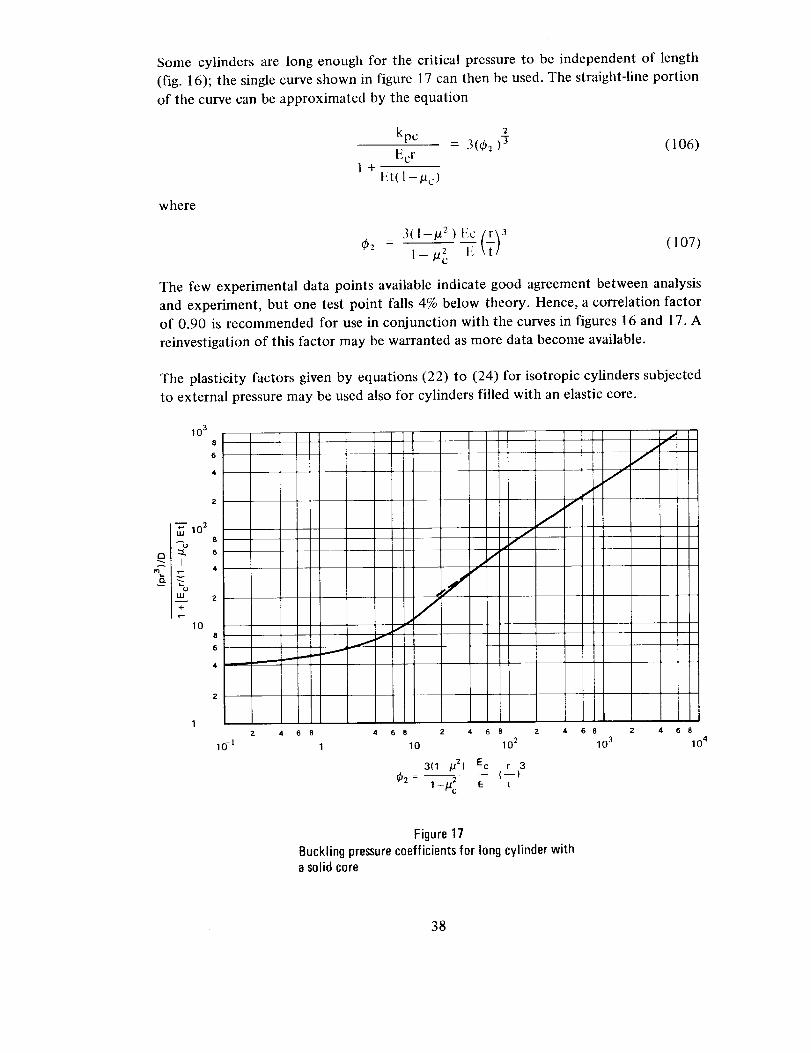
Some cylinders are long enough for the critical pressure to be independent of length
(fig. 16); the single curve shown in figure 17 can then be used. The straight-line portion
of the curve can be approximated by the equation
kp c 2= 3(0: )-$ (106)
Ecr
1+Et(1-ta c)
where
(t)3O:- l-._, e
(107)
The few experimental data points available indicate good agreement between analysis
and experiment, but one test point falls 4% below theory. Hence, a correlation factor
of 0.90 is recommended for use in conjunction with the curves in figures 16 and 17. A
reinvestigation of this factor may be warranted as more data become available.
The plasticity factors given by equations (22) to (24) for isotropic cylinders subjected
to external pressure may be used also for cylinders filled with an elastic core.
103
8
6
4
2
_"_ I02 8
m _ 4
2 _
10 i
8 I6 j_
4 i
2
10 -1
[4 6 8
!I '
,AI*
6 8 2 4
10
3( 1 _/_2 )
- 2q2 1-/a c
J/
6
0 2
Ec r 3
(--)E t
jI
I
,IJ
i
2 4 6 8 2
10 3
4 6 8
10 4
Figure 17Bucklingpressurecoefficientsfor longcylinderwitha solidcore
38

4.5.3 Torsion
The buckling behavior of cylindrical shells with an elastic core is analytically described
in reference 67 and is shown graphically in figure 18.
For small values of 4)3,_3 < 7, the analytical results can be approximated by
T- 1 + 0.16_3 (108)
Tcr
where
I_c V r 2
and %r is the torsional buckling stress given by equation (26), with 3' equal to unity.
When _b3 is greater than 1O, the analytical results follow the curve
3
r _ 1 + 0.25 q53a (110)TCF
IA
b
v
10 286
4
2
108
6
4
2
186
4
2
10 -I86
4
2
10-286
4
2
10. 3
10.22 4 6 8 2
10. ]
Tcr
4 s s z 4 s s z 4 6 s a 4 6 s
1 10 10 2 10 3
Ec _ (_Lr}2(_3 -- E r t
Figure 18Torsional buckling coefficients for cylinders with an elastic core
39
Experimental data are not available for this loading condition. The experimental points
obtained for cylinders with an elastic core for axial compression and external pressure,
however, show better correlation with theory than the corresponding experimental
results for the unfilled cylinder. Hence, conservative design curves can be obtained by
calculating rcr in equations (108) and (110) with the conelation and plasticity factors
for isotropic cylinders of equations (28) and (29).
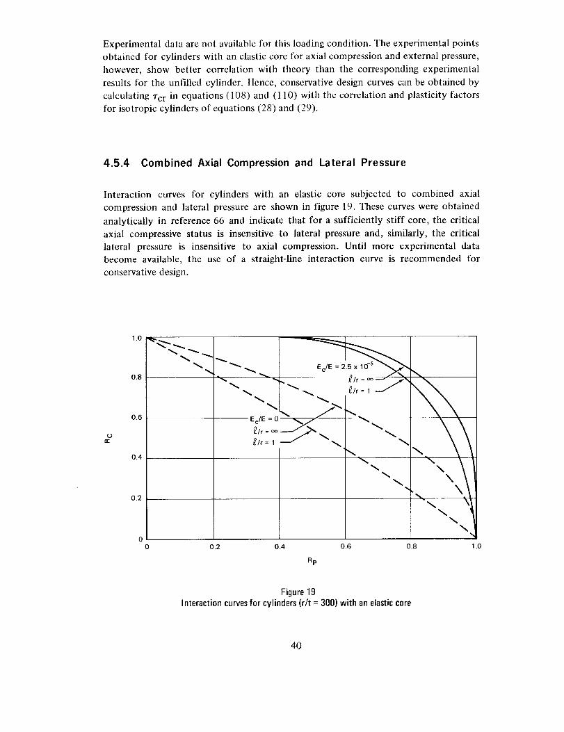
4.5.4 Combined Axial Compression and Lateral Pressure
Interaction curves for cylinders with an elastic core subjected to combined axial
compression and lateral pressure are shown in figure 19. These curves were obtained
analytically in reference 66 and indicate that for a sufficiently stiff core, the critical
axial compressive status is insensitive to lateral pressure and, similarly, the critical
lateral pressure is insensitive to axial compression. Until more experimental data
become available, the use of a straight-line interaction curve is recommended for
conservative design.
re-
1.0 __
0.8
0.6
0.4
0.2
"xx x e/r-,--//
Ec/E = 0__//" _
_/r =_ _ !
_/r = 1
\ \
\\
\
0 0.2 0.4 0.6 0.8 1.0
Rp
Figure 19Interaction curvesfor cylinders(r/t = 300) with an elasticcore
4O
4.6 Design of Rings
Little information is available on which to base the design of rings for cylinders not
intended to be subject to general instability failures. The criterion of reference 68 is
frequently cited as applicable to cylinders subjected to bending or compression.
Unfortunately, this criterion is empirical and is based on data from test cylinders with
proportions of little interest in contemporary design. A few checks made on cylinders
in use have indicated that the criterion usually is conservative, but this may not be so
in certain cases. See references 29 and 69.
A less direct procedure for designing rings may be used. It consists simply of
calculating the failing load of the cylinder in the so-called general-instability mode,
which involves failure of the rings, as well as calculation of the failing load of the
cylinder for wall failure between rings. Both calculations are made for several ring
weights. If such calculations are plotted against ring weight, the weight necessary to
force failure in the desired mode can be ascertained. In addition, the amount of error
in weight from uncertainties in the calculations can be judged. Presumably, there may
be some interaction between failing modes; thus, somewhat heavier rings than those
indicated by the calculations should be used.
This method of designing rings is, of course, applicable to all types of loading and to all
types of wall construction. It also has the advantage of giving the designer some feeling
for the influence of the various factors which determine ring weight.
A study of references 69 and 70, which present general linear analyses of ring-stiffened
isotropic cylinders in torsion and of orthotropic cylinders in compression, indicates
that the recommended procedure gives the same result as general theory for all
cylinders except those with a single ring dividing the cylinder into two equal bays.
41

REFERENCES
1. Almroth, B.O.; Bushnell, D.; and Sobel, L.H.: Buckling of Shells of Revolution
with Various Wall Constructions. Vols. I, II, and III. NASA CR 1049-1051, 1968.
2. Ball, R.E.: A Geometrically Nonlinear Analysis of Arbitrarily Loaded Shells of
Revolution. NASA CR 909, 1968.
3. Batdorf, S.B.: A Simplified Method of Elastic Stability Analysis for Thin
Cylindrical Shells. NACA Rept. 874, 1947.
4. Almroth, B.O.: Influence of Edge Conditions on the Stability of Axially
Compressed Cylindrical Shells. AIAA J., vol. 4, no. 1, Jan. 1966, pp. 134-140.
. Weingarten, V.I.; Morgan, E.J.; and Seide, P.: Elastic Stability of Thin-Walled
Cylindrical and Conical Shells Under Axial Compression. AIAA J., vol. 3, no. 3,
Mar. 1965, pp. 500-505.
6. Krivetsky, A.: Plasticity Coefficients for Plastic Buckling of Plates and Shells. J.
Aeron. Sci. (Reader's Forum), vol. 22, no. 6, June 1955, pp. 432-435.
7. Gerard, G.; and Becker, H.: Handbook of Structural Stability. Part II!, Buckling
of Curved Plates and Shells. NACA TN 3783, 1957.
8. Stowell, E.Z.: A Unified Theory of Plastic Buckling of Columns and Plates.
NACA Rept. 898, 1948.
. Seide, P.; Weingarten, V.I. ; and Morgan, E.J.: The Development of Design Criteria
for Elastic Stability of Thin Shell Structures. STL/TR-60-0000-19425
(AFBMD/TR-61-7), Space Technology Laboratory, Inc. (now TRW Systems),
Dec. 31, 1960.
10. Timoshenko, S.; and Gere, J.M.: Theory of Elastic Stability. Second ed.,
McGraw-Hill Book Co., Inc., 1961.
l 1. Sobel, L.H.: Effects of Boundary Conditions on the Stability of Cylinders Subject
to Lateral and Axial Pressures. AIAA J., vol. 2, no. 8, Aug. 1964, pp. 1437-1440.
43

12. Weingarten,V.I.; and Seide,P.: ElasticStability of Thin-WalledCylindricalandConicalShellsUnderCombinedExternalPressureandAxialCompression.AIAA J.,vol. 3, no.5, May1965,pp.913-920.
13.
14.
15.
16.
17.
18.
19.
20.
21.
22.
23.
24.
Gerard,G.: Handbookof StructuralStability.Supplementto PartIII Bucklingof CurvedPlatesandShells.NASATN D-163,1959.
Weingarten,V.I.; Morgan,E.J.; and Seide,P.: ElasticStability of Thin-WalledCylindrical and Conical Shells Under CombinedInternal Pressureand AxialCompression.AIAA J.,vol. 3,no.6, June1965,p. 1118.
Harris,L.A., et al.: The Stability of Thin-WalledUnstiffenedCircularCylindersUnderAxial CompressionIncludingthe Effectsof Internal Pressure.J.Aeron.Sci.,vol.24,no.8, Aug.1957,pp. 587-596.
Leonard,R.W.,et al.: Analysisof Inflated ReentryandSpaceStructures.Proc.Recoveryof SpaceVehiclesSymposium,Aug.-Sept.1960. Institute of theAeronauticalSciences,New York.
Leonard,R.W.;Brooks,G.W.;and McComb,H.G.,Jr.: StructuralConsiderationsof InflatableReentryVehicles.NASATN D-457,1960.
Stein,M.; and Hedgepeth,J.M.' Analysis of Partly Wrinkled Membranes.NASATN D-813,1961.
Anon." Collected Papers on Instability of Shell Structures, 1962.NASATN D-1510,1962.
Jones,R.M.: Bucklingof CircularCylindricalShellswith MultipleOrthotropicLayers and Eccentric Stiffeners. AIAA J., vol. 6, no. 12, Dec. 1968,pp. 2301-2305.
Stein,M.; and Mayers,J.: CompressiveBucklingof Simply SupportedCurvedPlatesandCylindersof SandwichConstruction.NACATN 2601,1952.
Becker,H.; andGerard,G.: ElasticStabilityof OrthotropicShells.J.Aeron.Sci.,vol.29,no.5, May1962,pp. 505-512,520.
Block,D.L.; Card,M.F.; and Mikulas,M.M.,Jr.: Buckling of EccentricallyStiffenedOrthotropicCylinders.NASATN D-2960,Aug.1965.
Hedgepeth,J.M.;andHall,D.B." Stabilityof StiffenedCylinders.AIAA J., vol. 3,
no. 12, Dec. 1965, pp, 2275-2286.
44
25.
26.
27.
Singer, J.; Baruch, M.; and Harari, O.: On tile Stability of Eccentrically Stiffened
Cylindrical Shells Under Axial Compression. International Journal of Solids and
Structures, vol. 3, no. 4, July 1967, pp. 445-470.
'l'asi, J.: Effect of Heterogeneity on tile Stability of Composite Cylindrical Shells
Under Axial Compression. AIAA J., vol. 4, no. 6, June 1966, pp. 1058-1062.
Van der Neut, A.: The General Stability of Stiffened Cylindrical Shells Under
Axial Compression. Rept. S-314, National Aerospace Research Institute
(Amsterdam), 1947.
28.
29.
30.
Dickson, J.N.; and Brolliar, R.H.: The General Instability of Ring-Stiffened
Corrugated Cylinders Under Axial Compression. NASA TN D-3089, Jan. 1966.
Meyer, R.R.: Buckling of
Uniform Axial Load and
July 1967.
Ring-Stiffened Corrugated Cylinders Subjected to
Bending. Rept. DAC-60698, Douglas Aircraft ('o.,
Peterson, J.P.; and Dow, M.B.: Compression Tests on ('ircular Cylinders Stiffened
Longitudinally by Closely Spaced Z Section Stringers. NASA Memo 2-12-59L,
1959.
31.
32.
33.
34.
Peterson, J.P.; Whitley, R.O.; and Deaton, J.W.: Structural Behavior and
Compressive Strength of Circular Cylinders with Longitudinal Stiffening.
NASA TN D-1251, 1962.
Becket, tt.; Gerard, G.; and Winter, R.: Experiments on Axial ('ompressive
General Instability of Monolithic Ring-Stiffened Cylinders. AIAA J., vol 1, no. 7,
July 1963, pp. 1614-1618.
Card, M.F.; and Jones, R.M.: Experimental and Theoretical Results for Buckling
of Eccentrically Stiffened Cylinders. NASA TN D-3639, Oct. 1966.
Milligan, R.: Gerard, G.; and Lakshinikanthanl, C.: General
Orthotropically Stiffened Cylinders Under Axial Compression.
no. ll,Nov. 1966, pp. 1906-1913.
Lastibility of
AIAA J., vol. 4,
35. Singer, J.: The Influence of Stiffener Geometry and Spacing on the Buckling of
Axially Compressed Cylindrical and Conical Shells. Preliminary Preprint Paper,
Second IUTAM Symposium on the Theory of Thin Shells, Copenhagen,
Sept. 1967.
45
36.
37.
38.
39.
40.
41.
42.
43.
44.
45.
46.
47.
Kaplan, A.; Morgan, E.J.; and Zophres, W.: Some Typical Shell Stability Problems
Encountered in the Design of Ballistic Missiles. Collected Papers on Instability of
Shell Structures. NASA TN D-1510, Dec. 1962, pp. 21-33.
Card, M.F.; and Peterson, J.P.: On the Stability of Orthotropic Cylinders.
Collected Papers on Instability of Shell Structures. NASA TN D-1510, Dec. 1962,
pp. 297-308.
Block, D.L.: Buckling of Eccentrically Stiffened Orthotropic Cylinders Under
Pure Bending. NASA TN D-3351, Mar. 1966.
Peterson, J.P.; and Anderson, J.K.: Bending Tests of Large Diameter
Ring-Stiffened Corrugated Cylinders. NASA TN D-3336, Mar. 1966.
Card, M.F.: Bending Tests of Large Diameter Stiffened Cylinders Susceptible to
General Instability. NASA TN D-2200, Apr. 1964.
Bodner, S.R.: General Instability of a Ring-Stiffened Circular Cylindrical Shell
Under Hydrostatic Pressure. J. Appl. Mech., vol. 24, no. 2, June 1957,
pp. 269-277.
Baruch, M.; and Singer, J.: Effect of Eccentricity of Stiffeners on the General
Instability of Stiffened Cylindrical Shells Under Hydrostatic Pressure. Journal of
Mechanical Engineering Science, vol. 5, no. 1, Mar. 1963, pp. 23-27.
Singer, J.; Baruch, M.; and Harari, O.: Further Remarks on the Effect of
Eccentricity of Stiffeners on the General Instability of Stiffened Cylindrical
Shells. Journal of Mechanical Engineering Science, vol. 8, no. 4, 1966,
pp. 363-373.
Kendrick, S.: The Buckling Under Extremal Pressure of Circular Cylindrical Shells
with Evenly Spaced Equal Strength Circular Ring Frames. Part IIl- Naval
Construction Research Establishment. Rept. R-244, Sept. 1953.
Galletly, G.D.; Slankard, R.C.; and Wenk, E., Jr.: General Instability of
Ring-Stiffened Cylindrical Shells Subject to Extremal Hydrostatic Pressure- A
Comparison of Theory and Experiment. J. Appl. Mech., vol. 25, no. 2, June 1958
pp. 259-266.
Simitses, G.J.: Instability of Orthotropic Cylindrical Shells Under Combined
Torsion and Hydrostatic Pressure. AIAA J., vol. 5, no. 8, Aug. 1967, pp. 1463-1469.
Baruch, M.; Singer, J.; and Well, T.: Effect of Eccentricity of Stiffeners on the
General Instability of Cylindrical Shells Under Torsion. Israel Journal of
Technology, vol. 4, no. 1, 1966, pp. 144-154.
46
48.
49.
50.
51.
52.
53.
54.
55.
56.
57.
58.
59.
60.
61.
Milligan,R.; and Gerard,G.: General Instability of Orthotropically StiffenedCylindersUnderTorsion. AIAA J., vol. 5, no. 11,Nov. 1967,pp. 2071-2073.
Dow,N.F.; Libove,C.; and Hubka,R.E.: Formulasfor the ElasticConstantsofPlatesWithIntegralWaffle-LikeStiffening.NACARept.1195,1954.
Crawford,R.F.; and Libove,C.: ShearingEffectivenessof Integral Stiffening.NACATN 3443,1955.
Meyer,R.R.: Buckling of 45° Eccentric-StiffenedWaffle Cylinders. J. Roy.Aeron.Soc.,vol.71,no.679,July 1967,pp. 516-520.
Peterson,J.P.; and Whitley,R.O.: Local Bucklingof LongitudinallyStiffenedCurvedPlates.NASATN D-750,Apr. 1961.
Anon.: SandwichConstructionfor Aircraft. PartII - Materials,Properties,andDesignCriteria.ANC-23,Air Force-Navy-CivilSubcommitteeon Aircraft DesignCriteria,1955.
Libove,C.; and Hubka,R.E.: ElasticConstantsfor CorrugatedCore SandwichPlates.NACATN 2289,1951.
Plantema,F.J.: SandwichConstruction,The Bendingand Bucklingof SandwichBeams,PlatesandShells.JohnWiley& Sons,Inc., 1966.
Zahn,J.J.; and Kuenzi,E.W.: ClassicalBuckling of Cylinders of SandwichConstructionin Axial Compression- OrthotropicCores.Rept.FPL-OI8.ForestProductsLaboratories,1963.
Anon.: CompositeConstruction for Flight Vehicles. Part I-Fabrication,Inspection,Durability, andRepair.MIL-HDBK-23,PartI, ArmedForcesSupplySupportCenter,Oct. 1959.
Peterson,J.P.: Weight-StrengthStudieson StructuresRepresentativeof FuselageConstruction.NACATN 4114,1957.
Norris,C.: Short-ColumnCompressiveStrengthof SandwichConstructionsasAffected by Size of HoneycombCore Materials.FPL-026,Forest ProductsLaboratories,Jan.1964.
KonishiD.Y., et al.: HoneycombSandwichStructuresManual.Rept.NA58-899,NorthAmericanAviation,Inc.,LosAngelesDivision,July 1968.
Yusuff,S.: FaceWrinklingandCoreStrengthin SandwichConstruction.J.Roy.Aeron.Soc.,vol.64,no.591,Mar.1960,pp. 164-167.
47
62. Harris,B.; and Crisman,W.: Face-WrinklingMode of Buckling of SandwichPanels.EM3,ASCEJournalof Engineering,MechanicsDivision,June1965.
63. Kiciman,M.O.; andKonishi,D.Y.: Stability of HoneycombSandwichCylinders.PaperNo. 61-AV-36,ASME,1961.
64. Holston,A.,Jr.: Stability of lnhomogeneousAnisotropic Cylindrical ShellsContainingElasticCores. AIAA J., vol. 5, no. 6, June 1967,pp. 1135-1138.
65. Brush,D.O.;andPittner,E.V.: Influenceof CushionStiffnesson theStabilityofCushion-LoadedCylindricalShells.AIAA J.,vol. 3,no.2, Feb.1965,pp. 308-316.
66. Seide,P.: The Stability Under Axial Compressionand Lateral Pressureof aCircular-CylindricalShell with an ElasticCore. J. Aeron. Sci., vol. 29. no.7,July 1962,pp.851-862.
67. Weingarten,V.I.: Stability Under Torsion of Circular Cylinder ShellsWith anElasticCore.ARSJ.,vol.82,no.4, Apr. 1962,pp.637-639.
68. Shanley,F.R.: Weight-StrengthAnalysis of Aircraft Structures.McGraw-HillBookCo.,Inc., 1952.
69. Block,D.L.: Influenceof RingStiffenerson Instability of OrthotropicCylindersin Axial Compression.NASATN D-2482,1964.
70. Stein,M.; Sanders,J.L.; andCrate,H.: Critical Stressof Ring-StiffenedCylindersin Torsion.NACARept.989,1950.
48
NASA SPACE VEHICLE DESIGN CRITERIA
MONOGRAPHS ISSUED TO DATE
SP-8001
SP-8002
SP-8003
SP-8004
SP-8005
SP-8006
SP-8008
SP-8009
SP-8010
SP-8011
SP-8012
SP-8014
SP-8015
(Structures)
(Structures)
(Structures)
(Structures)
(Environment)
(Structures)
(Structures)
(Structures)
(Environment)
(Environment)
(Structures)
(Structures)
(Guidance and
control)
Buffeting During Launch and Exit, May 1964
Flight-Loads Measurements During Launch and Exit,
December 1964
Flutter, Buzz, and Divergence, July 1964
Panel Flutter, May 1965
Solar Electromagnetic Radiation, June 1965
Local Steady Aerodynamic Loads During Launch and
Exit, May 1965
Prelaunch Ground Wind Loads, November 1965
Propellant Slosh Loads, August 1968
Models of Mars Atmosphere (1967), May 1968
Models of Venus Atmosphere (1968), December 1968
Natural Vibration Modal Analysis, September 1968
Entry Thermal Protection, August 1968
Guidance and Navigation for Entry Vehicles,November 1968
NASA-Langley, 1969 -- 32 49