budgit electric hoists & trolleys - j. herbert corp electric hoists and trolley brochure.pdf ·...
TRANSCRIPT

BUDGIT® ELECTRIC HOISTS & TROLLEYS

For over 60 years, BUDGIT® Electric Chain Hoists have been designed and manufactured for tough jobs. Since 1935, BUDGIT® has led the industry in innovation, quality, and dependability. These compact, lightweight, economical hoists are built to withstand the rigors of heavyservice and repeated lifting cycles. They are easy to service, require minimalmaintenance, and offer excellent headroom.
BUDGIT® hoists come with two choices of load chain; roller and link.Roller chain provides smoother, quieter operation for light to mediumduty applications. Roller chain models are available only in hook suspension. Link chain hoists are ideal for heavier service applicationsrequiring repeated lifting cycles. All link chain models are available ineither hook or lug suspension.
All BUDGIT® electric hoists are equipped with a heavy duty, positive acting, short-stroke DC rectified disc motor brake.The brake is rated at 150% torque to stop and hold the load. In addition, all hoists are provided with a Weston-type mechanicalload brake for load lowering control and as a backup to the hoistmotor brake. A Manguard™ overload device is also standard on allBUDGIT® Electric Chain Hoists. The Manguard™ protects thehoist, operator and supporting structure by preventing dangerous overloads.
A wide variety of trolleys are provided for both hook and lug-suspended hoists. Trolleys are available in push, hand-gearedand motor-driven versions. Hook-on trolleys are available ineither push or hand-geared versions. Rigid Mount trolleysare available in push, hand-geared and motor-driven versions.
BUDGIT® hoists are available in a variety of controls to meet the specific need of your application. The standard control is single speedwith options available for two speed and variablefrequency. All BUDGIT® electric hoists and/or motor-driven trolleys are CSA approved.
There’s a BUDGIT® for every job.
2
Elec
tricC
hain
Hoi
sts
BUDGIT ’S ® first portable electric hoist was a reliable workhorse.
Today, decades later, many are still in service.

3
S P E C I F I C A T I O N S
Capacity Range : 1/4 thru 3-tonsLift : 10 feet standard
additional lifts availableLifting Speed : 5 to 64 FPM
AC Power Supply : 115/230 1-60 HZ Reconnectable230/460-3-60 Reconnectable208 and 575-3-60 Single Voltage
Control : Push-button control voltage of 115 volts standard on all 3 phase models, single speed, two speed and single phase models.
Suspensions : Hook and Lug
High-torque, heavy duty hoist motor. Motors are 30-minute rated with class “B” insulation provided with a thermal actuated switch (TAS) embedded in the motor winding for protection.
Motor brake is a 150% torque, DC rectified short stroke, spring set disc brake for positive braking action and long life with minimal maintenance.
Load sprocket is provided with a full floating chain guide that assures proper engagement of chain on sprocket.
All gearing is totally enclosed, oil-bath lubricated for long life.
Hoists are available in either roller or link chain.
The lower block is provided with a 360˚ rotating hook ridingon thrust bearings. As standard, the hook is provided with aspring loaded latch.
The hoist frame and housing are constructed from light-weight, rugged aluminum alloy. Housing is precisionmachined for accurate gear and bearing alignment.
All hoists are provided with mechanical load brake and Manguard™ overload protection. The load brake provides load lowering controland a backup for the DC disc motor brake. Manguard™
prevents lifting loads beyond the hoist’s load range whichmay damage the hoist.
Hoist control is located under a removable cover for easy access. Reduced control circuit voltage of 115 voltsis standard.
All hoists are provided with an upper and lower control circuit limit switch.
Hoists are available in either hook or lug suspension. Hook suspension permits portability of the hoist while lugsuspension reduces headroom and can be used with any ofour rigid-mount trolleys.
(Not Shown) Standard push-button control station is contoured for operator comfort allowing easy one-handedsure grip control and provided with a weatherproofNEMA-4X enclosure. The push-button cable is providedwith built-in strain relief to help prevent cable damage.
11
4
8
9
6
5
10
7
3
1
2
1
2
3
4
6
5
7
8
9
10
11

4
BUDGIT® HOOK & LUG MOUNTED HOISTS
HOOK & LUG MOUNTED HOISTS WITHPUSH AND HAND-GEARED TROLLEYSOne and Two Speed Hoists
DimensionsLift Electric Parts Hoist Net
Capacity Speed Motor Current of Catalog Wt. A B C D(tons) (fpm) H.P. Phase Chain Number (lbs) (in) (in) (in) (in)
16 1/4* SingleBEH2516 79
Three
1/4 32 1/2Single
1 BEH2532 82 153/4 111/16 51/8 65/16Three
64 1__
BEH2564 78Three
16 1/2Single
BEH5016 82Three
11/232 1
SingleBEH5032 83
153/4 111/16 51/8 6 5/16
Three
8 1/2Single
BEH0108 90Three
1 16 1Single
1 BEH0116 91 16 9/16 111/16 5 1/8 65/16Three
32 21/2
__BEH0132 96
Three
4 1/2Single
BEH0204 115Three
2 8Single
BEH0208 116 221/4 12 13/16 67/16 47/81Three
2
16 21/2
__BEH0216 117
Three
5 1Single
BEH0305 156Three
3310 21/2
__BEH0310 166
24 143/8 7 3/4 73/8
Three
CATALOG NUMBERS, SPECIFICATIONS & DIMENSIONS (Push and hand-geared trolleys)
Lug Mounted
* Two speed hoist has a 1/2 H.P. motor

5
BUDGIT® HOOK & LUG MOUNTED HOISTS
HOOK & LUG MOUNTED HOISTS WITHPUSH AND HAND-GEARED TROLLEYSOne and Two Speed Hoists
E M
One Two G J (std. flangeSpeed Speed Pin Diameter H Max. K L width) N
(in) (in) (in) (in) (in) (in) (in) (in) (in)
107/8__
11 __
113/8__
11 111/2
5/8 915/16 35/8 15 3/8 35/8___ 31/8
11 __
11 121/16
113/8__
11 111/2
121/8__ 5/8 915/16 35/8 15 3/8 35/8
___ 31/8
111/2 121/16
113/8__
11 111/2
121/8__
111/2 121/16
5/8 915/16 3 5/8 165/16 35/8 93/4 31/8
__ __
12 14113/8
__
11 __
121/8__
111/2 121/161 1011/16 43/8 201/16 43/8 101/4 5
__ __
12 14121/8
__
111/2 121/16__ __ 11/4 127/8 6 241/2 6 183/8 6
12 14
CATALOG NUMBERS, SPECIFICATIONS & DIMENSIONS (Push and hand-geared trolleys)
Hook Mounted

6
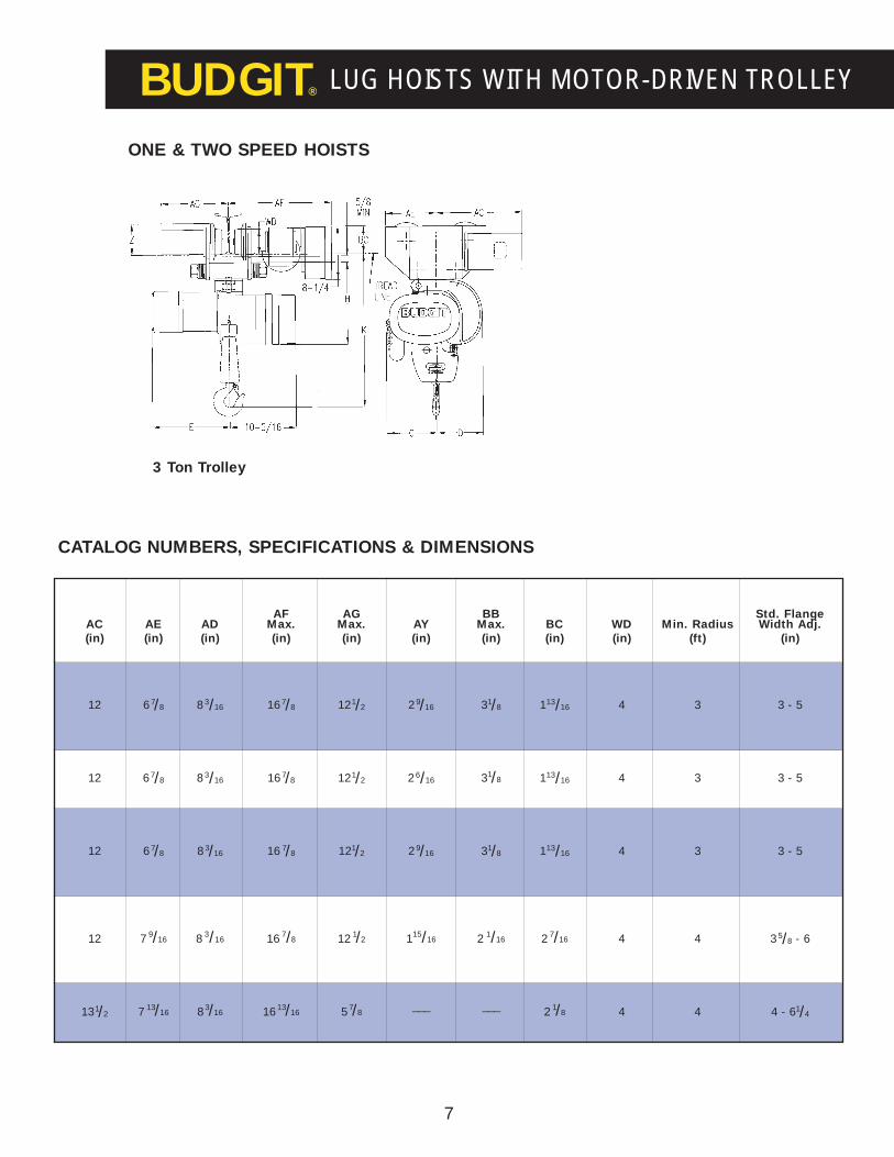
BUDGIT® LUG HOISTS WITH MOTOR-DRIVEN TROLLEY
ONE & TWO SPEED HOISTS
ELift Electric Parts Hoist Net
Capacity Speed Motor Current of Catalog Wt. C D One Speed Two Speed H K Z(tons) (fpm) H.P. Phase Chain Number (lbs) (in) (in) (in) (in) (in) (in) (in)
16 1/4*SINGLE
BEH2516 164 107/8___
THREE 11 ___
1/4 32 1/2SINGLE
1 BEH2532 167 51/8 65/16113/8
___615/16 15 3/8 47/8THREE 11 111/2
64 1___
BEH2564 16311 ___
THREE 11 121/16
16 1/2SINGLE
BEH5016 167113/8
___
THREE1
11 111/21/232 1
SINGLEBEH5032 168
51/8 65/16211/8
___ 915/16 15 3/8 47/8
THREE 111/2 121/16
8 1/2SINGLE
BEH0108 175113/8
___
THREE 11 111/2
1 16 1SINGLE
1 BEH0116 176 51/8 6 5/16211/8
___915/16 15 3/8 47/8THREE 111/2 121/16
32 21/2
___BEH0132 181
___ ___
THREE 12 14
4 1/2SINGLE
BEH0204 210113/8
___
THREE
2
11 ___
2 8 1SINGLE
BEH0208 211 67/16 47/8121/8
___1011/16 201/16 47/8THREE 111/2 121/16
16 21/2
___BEH0216 212
___ ___
THREE 12 14
5 1SINGLE
BEH0305 296 121/8___
THREE3 111/2 121/163
10 21/2
___BEH0310 306
7 3/4 7 3/8 ___ ___ 12 7/8 241/2 47/8
THREE 12 14
CATALOG NUMBERS, SPECIFICATIONS & DIMENSIONS
1/4 - 1 Ton & 2 Ton Trolley
* Two speed hoist has a 1/2 H.P. motor
7
BUDGIT® LUG HOISTS WITH MOTOR-DRIVEN TROLLEY
AF AG BB Std. FlangeAC AE AD Max. Max. AY Max. BC WD Min. Radius Width Adj.(in) (in) (in) (in) (in) (in) (in) (in) (in) (ft) (in)
12 67/8 83/16 167/8 121/2 29/16 31/8 113/16 4 3 3 - 5
12 67/8 83/16 167/8 121/2 26/16 31/8 113/16 4 3 3 - 5
12 67/8 83/16 16 7/8 121/2 29/16 31/8 113/16 4 3 3 - 5
12 7 9/16 8 3/16 16 7/8 12 1/2 115/16 2 1/16 2 7/16 4 4 35/8 - 6
131/2 7 13/16 83/16 1613/16 57/8___ ___ 2 1/8 4 4 4 - 61/4
ONE & TWO SPEED HOISTS
CATALOG NUMBERS, SPECIFICATIONS & DIMENSIONS
3 Ton Trolley

8
BUDGIT® HOOK SUSPENSION TROLLEYS
Hand-GearedPush TrolleyTrolley*
Min. Adjustable Min.Net Net Beam For Flange Radius Curve
Capacity Catalog Wgt. Catalog Wgt. Depth** Widths Trolley Will(tons) Number (lbs.) Number (lbs.) (in) (in) Negotiate
† 1/480 13 __ __
42 5/8 to 45/8 2’ - 6”80WFA 14 5 to 7
† 1/281 13 __ __
42 5/8 to 45/8 2’ - 6”81WFA 14 5 to 7
† 182 25 82G 39
53 to 5
3’ - 0”82WFA 26 82GWFA 38 5 to 782WFB 27 82GWFB 40 7 to 9
† 283 35 83G 48
63 3/8 to 6
4’ - 0”83WFA 36 83GWFA 49 6 to 883WFB 37 83GWFB 50 8 to 10
3905480 41 905490 65
633/8 to 6
4’ - 0”905481 43 905491 67 61/8 to 87/8905482 44 905492 68 9 to 11
CATALOG NUMBERS AND SPECIFICATIONS
OUTLINE DIMENSIONS (IN)
Cap. Catalog Max.(tons) Number A B C D WD F* H** J L M***
1/4 80 43/8 27/16 41/8 1 31/8 21/8 7 9/16 311/167/8 ------
1/2 81 4 3/8 2 7/16 41/8 1 31/8 21/8 7 9/16 311/167/8 ------
82 61/8 3 9/16 51/8 11/8 4 219/32 81/4 49/16 1 ------
1 82G 6 1/8 3 9/16 51/8 11/8 4 2 39/64 81/4 5 1 10 3/16
83 6 7/8 313/16 53/4 15/16 415/16 223/32 83/4 51/2 11/8 ------
283G 67/8 313/16 53/4 15/16 415/16 223/32 83/4 513/16 11/8 109/16
905480 6 7/8 4 3/8 6 15/8 415/16 253/64 12 513/16 17/16 ------
3905490 67/8 4 3/8 6 15/8 415/16 2 53/64 12 513/16 17/16 185/16
Push Type Trolley 1/4, 1/2, 1 & 2 Ton
3 Ton
Hand-Geared Trolley 1,2 & 3 Ton
* Hand-geared trolleys have standard chain drop of 9’-6”. Longer chain available. ** When used on smallest I-beam size, beam must be free of allobstructions such as clips, suspension bolts and nuts. If beam is welded to cross trusses, spacers must be used between top of beam and truss to provide wheel flange clearance. Track must be supported from ends only as wheel flanges will be above top of I-beam. † Metric Rated Trolleys.
* Dimension “F” is based on standard BUDGIT® Hoisthook and smallest size beam on which trolley will operate.Dimension decreases slightly for larger beam sizes.
** Dimension “H” is based on standard trolley, WFA and Btrolleys have greater dimensions.
*** Dimension “M” occurs on the smallest beam only. On larger beams, this dimension is increased by the difference in flange width.
HOOK SUSPENSION TROLLEYS (For use only with hook-type hoists)BUDGIT® hook suspension trolleys are available in push and hand-geared versions to run on either American Standard Section I-Beams or wide flange beams.
The trolley sides are of all-steel construction for maximum strength. The wheels are steel with hardened treads and roller bearings for easy traversing and long life. Self aligning frames keep the load equally distributed, and are adjustable to fit several sizes of beams.
Push trolleys are an economical alternative for low duty cycle, lighter capacity applications with lifts under 20 feet. Push trolleys are available in capacities from 1/4 to 3 tons. 1/4 thru 2 ton capacity are metric rated.
Hand-geared trolleys are designed for applications requiring close control of horizontal movement of the hoist and itsload. They are also ideal for those applications where an operator shouldn’t be near or touch the load to move or positionit. The trolleys are available in capacities from 1 thru 3 tons. The 1 and 2 ton trolleys are metric rated.

9
BUDGIT® RIGID MOUNT TROLLEYSRIGID MOUNT TROLLEYS (For use only with lug-suspended hoists)Push and Hand-Geared Type (Capacities: 1/4 thru 3-ton)
These Rigid Mount Trolleys are designed especially for use with lug suspended hoists. The trolleys attach directly to lug brackets on the hoists, thereby forming integral trolley-hoist combinations, offering close headroom dimensions _ making the trolley-hoist ideal for applications where distance from floor to I-beam is limited.
The trolleys are of all-steel construction to provide maximum strength. Wheels have hardened treads, ensuring long life, and operate on ball bearings for easy travel. Pressure fittings are provided in wheel axles to simplify lubrication.
On hand-geared models, the hand chain operated wheel turns a pinion which meshes with steel gears for ease of operation andaccurate spotting. The chain guide keeps the chain aligned with the wheel and helps prevent fouling. The wheel gears and drivepinion have machine cut teeth.
Anti-tilt rollers are provided on hand-geared trolleys to eliminate the tilting of trolley on beam when operating with a light loador without a load.
Hand-GearedPush Trolley Trolley* **
Min. Adj forNet Net Beam Flange Min. ****
Cap. Cat Wt. Cat Wt. Depth Widths Curve F G J M(tons) No. (lbs) No. (lbs) (in) (in) Rad A B C D WD Max. DIA. H Max. Max.
1/2 905401 15 __ __ 4 25/8 to*** 45/8 2’ 6” 43/8 25/8 33/1611/16 31/8 15/8
5/8 81/8 311/16__
905402 23 __ __ 3 to 529/16
87/8__
1905405 24 __ __
551/4 to 7 3/8
3’ 6” 61/8 37/811/16 4 17/8
5/8111/8
5__
__ __ 905411 40 3 to 539/16
87/8 93/4
__ __ 905413 41 51/4 to 73/8 111/8 111/8
2905403 43 905412 57
633/8 to 6
4’ 0” 6 7/8 313/16 47/16 1 415/16 2 1101/8
513/16101/4
905406 44 905414 58 61/4 to 87/8 13 117/8
905404 50 905417 65 3 3/8 to 6 12 3/4 183/8
3 905407 52 905418 67 6 61/8 to 87/8 4’ 0” 67/8 43/16 53/4 13/8 415/16 31/4 11/4 153/4 513/16 197/8
905408 54 905419 69 9 to 11 177/8 211/8
900211 35 900261 50 3 to 5 87/8 109/16
1 900212 38 900262 53 6 51/8 to 71/4 3’ 0” 75/8 3 37/83/4 4 17/8
5/8 111/4 47/8 1111/16
900213 41 900263 56 71/2 to 91/8 123/4 125/8
900221 45 900271 60 33/8 to 6 91/2 101/16
2 900222 48 900272 63 6 61/4 to 85/8 4’ 0” 91/8 3 41/8 15/16 4 21/8 1 121/8 47/8 113/8
900223 51 900273 66 87/8 to111/4 143/4 1211/16
900231 55 900281 70 4 to 6 1/4 12 161/2
3 900232 58 900282 73 6 63/8 to 85/8 4’ 0” 91/8 31/4 41/2 13/8 4 21/2 11/4 143/8 47/8 1711/16
900233 62 900283 77 83/4 to 11 163/4 187/8
HEAVY DUTY RIGID MOUNT TROLLEYS – PUSH & HAND-GEARED
N
31/8
31/8
5
6
31/8
5
6
Push Type Trolley 1/4, 1/2 & 1 Ton 2 & 3 Ton Hand-Geared Trolley 1/2, 1, 2 & 3 Ton
Heavy DutyRigid Mount
Trolleys
OUTLINE DIMENSIONS (IN)
* Hand-geared trolleys have standard hand chain drop of 9’- 6”. Longer chain available. ** When used on smallest I-Beam size, beam must be free of allobstructions such as clips, suspension bolts and nuts. *** For 1/4 and 1/2 ton applications on wider flange beams, mount on 1 ton trolleys. **** Dimension “F” isbased on largest size beam on which trolley will operate. Dimension increases slightly for each of the smaller beam sizes.
RIGID MOUNT TROLLEYS – PUSH & HAND-GEARED

10
BUDGIT® MOTOR-DRIVEN TROLLEYS
MOTOR-DRIVEN TROLLEYS For use only with lug-suspended hoists
BUDGIT® motor-driven trolleys are designed to operate with BUDGIT®
lug mounted hoists...attaching directly to the hoist suspension lug, formingan integral hoist/trolley combination. Motor-driven trolleys are ideal forheavier duty cycles or applications with heavier capacities andlonger lifts and applications where the operator can not touchor be near the load.
Motor-driven trolleys are offered in capacities from 1/4 to 3tons to cover the entire range of BUDGIT® electric chainhoists. The trolleys are provided with a four button pendantstation as standard for controlling the hoist and trolleymotions. The pendant station uses control voltage from thehoist control.
• Steel frame side plates extend beyond thewheels for end stop contact. Side plates havetapped holes for collector bracket attachment.
• Wheels are forged heat-treated steel withcontour tread for use on American Standard I-Beams or wide flange beams.
• Traverse motor is 30-minute rated, totallyenclosed non-ventilated with class “F” insulation and TAS as standard.
• Traverse gearing is housed in a heavy dutyright angle drive reducer with output pinionmeshing with machine cut wheel gears.
• Trolley controls are housed in a NEMA 1enclosure mounted on the trolley side for easyaccess. The controls include a reversing con-tactor, terminal strip and NEMA 4X pendantstation with hoist and trolley push-buttoncontrols as standard.
SIZES, CATALOG NUMBERS & SPECIFICATIONS MOTOR-DRIVEN TROLLEY FOR USE WITH SINGLE OR TWO SPEED HOISTS
Some of the superior construction features of the BUDGIT ® Motor-driven trolleys are:
Extended Adjustmentswith price added to std. Optional
Standard SpecialCatalog Net Std. Width 1st Ext. 2nd Ext. Trolley Speeds Speed MotorNumber Wt. Adjustment Flange Adj. Flange Adj. Speed (fpm) (fpm) H.P.
1/4 to 1 Ton Capacity
MDT01 85# 33/8” - 5” 51/8” – 71/4” 71/2” – 91/8” 75 fpm 50 & 100 25, 150 1/4
2 Ton Capacity
MDT02 95# 35/8” - 6” 61/4” – 85/8” 87/8” – 111/4” 60 fpm 40 & 80 30, 120 1/4
3 Ton Capacity
MDT03 140# 4” - 61/4” 63/8” – 85/8” 83/4” – 11” 50 fpm 75 & 100 25, 125 1/4
Always specify voltage when ordering. Voltages available: 115/230-1-60, 208-230/460-3-60, 575-3-60115/230-1-60 is not available on trolleys for two speed hoists or two speed trolleys.Two speed trolleys have a 3:1 speed ratio. Standard pendant drop from trolley is 7 feet. Longer cables are available.Trolleys are equipped with 3-foot length power supply cable. Longer lengths are available.

11
1/4 thru 1 Ton 2 Ton 3 TonDimensions Capacity Capacity Capacity C
AC 12” 12” 131/2”
AD 83/16” 83/16” 83/16”
AF Max. 167/8” 167/8” 1613/16”
AG Max. 121/2” 121/2” 57/8”
AU 37/8” 41/8” 41/2”
AV 3/4” 115/16” 13/8”
AY 29/16” 115/16”___
BB Max. 31/8” 21/16”___
BC 113/16” 27/16” 21/8”
G Dia. 5/8” 1” 11/4”
N 31/8” 5” 6”
U 73/4” 91/8” 91/8”
V 3” 3” 31/4”
Z 47/8” 47/8” 47/8”
WD 4” 4” 4”
Min. Radius 3’ 4’ 4’Standard Flange 3” - 5” 35/8” - 6” 4” - 61/4”
Width Adjust.
BUDGIT® MOTOR-DRIVEN TROLLEYS
OUTLINE DIMENSIONS
1/4 - 1 Ton & 2 Ton Trolley
3 Ton Trolley
HEAVY DUTY RIGID MOUNT TROLLEYS
If using a NEMA 4/12 panel, consult factory for dimensions due to add-on of counterweights.

12
BUDGIT® OPTIONS & ACCESSORIES
HOOK SUSPENSIONStandard on all electric hoists.Hook suspension providesportability allowing the hoist tobe moved throughout a facility.
HEAVY DUTY RIGID MOUNTTROLLEYS FOR HEAVY DUTYSERVICE TRAVERSE APPLICATIONSDesigned for use specifically withBUDGIT® lug mounted electricchain hoists. The wheels are heattreated forged steel with dual treaddesign for operation on either “S”or wide flange beams. Sealed precision ball bearings and heavygauge steel side plates provide aheavy duty unit.
LINK CHAINLink chain hoists are ideallysuited for applications requiringheavier capacities, faster hoist-ing speeds and/or heavier dutycycles.
LUG SUSPENSION BRACKETSUsed to convert hoists from hookto lug suspensions, link chain only.Must be used to accommodaterigid mount push, hand-geared.and motor-driven trolleys.
LUG SUSPENSIONLug suspension is optional andprovides shorter headroomthan hook suspension. Lug suspension is available only for link chain hoists and motor-driven trolleys must use lugsuspension.
PUSH-BUTTON STATIONAll motions can be controlledfrom a convenient, easy to operateNEMA 4X push-button station.Push-button stations are availablefor one and two speed, or variablefrequency applications.
ROLLER CHAINRoller chain hoists run quieterthan link chain hoists but areintended for light to mediumduty cycle applications
CABLE REELSSpring loaded reels keep powerconductor cables taut and out ofthe way. Suitable for use withBUDGIT® and other electrichoists and trolleys. Cable reel isstationary type with a 340° pivotbase.

13
BUDGIT® OPTIONS & ACCESSORIES
CABLE SUSPENDED FESTOONINGCable suspended festoon crossconductor systems are an effective way to electrify shortspan monorails, bridge cranes,and jib cranes.
SHIELDED BAR CONDUCTORSShielded figure “8” bar conductorsystems are designed to meet average conductor reqirements for cross conductor and runwaysystems up to 300’ long withoutengineering or layout expense.
TRACK SUSPENDED FESTOONINGAn efficient and economicalway to electrify longer span,heavier duty crane bridges andmonorail systems. Also availablefor festoon pendant control stations
VARIABLE FREQUENCY DRIVESVariable frequency drives providesmooth ramped acceleration anddeceleration and precise load spotting while lessening impact on the drive train and allowingthe motor to run cooler. They areavailable for all BUDGIT®
electric chain hoists.
CURRENT COLLECTORSSlide-type collectors are used for shielded figure “8” conductor bar systems.Collector arrangements typically consist of a collector pole and mountingplate with one collector shoefor each conductor in the conductor system.
CHAIN CONTAINERSChain containers eliminatehanging tail chains by providing a storage containerfor the chain. They are easilyinstalled and accept the chainin a way that will not kink or twist the chain.
AVAILABLE OPTIONS & ACCESSORIES• TROLLEY ELECTRICAL ADAPTER KITS
Field conversion kit when it is desired to modify existing lug mount hoists forpush and hand-geared trolleys to lug mount for motor-driven trolleys.
• TROLLEY ADAPTER LINKS
Make it possible to hang hook mounted hoists on trolleys of larger capacities• CONDUCTOR CORD TROLLEYS
For supporting conductor cords along the monorail beam.• WATERPROOF COVERS
Recommended for electric hoists subjected to outdoor usage.• WEATHERPROOFING
Including weatherproof cord grips, sealing of electrical joints and zinc-plated load chain.
• CORROSION RESISTANT/PLATING SERVICES
Including zinc-plated load chain and hooks, zinc-plated or anodized lower block,zinc chromate primer, motor shaft seal and sealing of electrical joints.
• RETRACTILE CORD
Keeps power cord from dragging, neoprene jacketed, 20’-0” extended length.• MAINLINE DISCONNECT PANEL
Including trolley mounted disconnect, stop-start buttons on push-button, hoist and trolley fusing
• NEMA 4 & 3R TROLLEY CONTROLS ARE AVAILABLE
• ADDITIONAL POWER SUPPLY CABLE
• TWO SPEED TROLLEYS
3:1 reduction of speeds.• TROLLEY BRAKE
• ELECTRONIC ACCELERATION CONTROL AND BALLAST RESISTORS
For cushioned starting.• FUSE PANEL

HOW TO DETERMINE YOURHOIST REQUIREMENTS
Hoist CapacityDetermine the maximum load to be lifted. If the load fallsbetween standard rated capacities, always go to the highercapacity. (i.e., for 4,300 lb. maximum load, use 6,000 lb.,3 ton capacity hoists.)
Hoist LiftTo determine the total lift required, measure the distancefrom the bottom of the beam to the lowest point on thefloor to be reached and subtract the hoist headroomdimension shown in the specifications. The remaining distance is the lift required on the hoist. Always select astandard lift equal to or greater than the distance required.
Hoist SuspensionHook type suspension allows hoist to be hung almost anywhere and is used when hoist must be readily movedto other locations. Lug type saves headroom and is usedwith rigid mount trolleys or when hoist is permanentlymounted in a fixed location.
Trolley TypeThere are three standard trolley types that can be used tosuspend BUDGIT® Hoists.
Push Trolley -Recommended for light capacities and lifts below 20 feet. An economical method for moving loads.
Hand-Geared Trolley -Offers most precise control for load spotting. Most favorable for higher capacities and short monorails where the control is desired. Also recommended where lifts are above 20 feet.
Motor-Driven Trolley -Most widely used method of suspension, particularly 2 ton capacity and above. Virtually a necessity where long monorails are used.
BUDGIT® HOIST TROLLEY SELECTION
HOW TO SELECT THE CORRECT BUDGIT® MANGUARD™
ELECTRIC HOISTFirst _Determine amount of travel /liftrequired per hour
This can easily be done by taking the distance a loadmust be lifted and lowered then multiplying by the number of times this must be done per hour to do thejob required. Always use maximums that can be expectedto occur. Example: Must lift pipe six feet to rack thenlower hook for the next load 20 times per hour.
Second _Count the number of starts needed per hour
“Starts” are the actuations of the push-buttons. In ourexample, let’s assume, under a maximum condition, thatin the raise cycle the hoist push-buttons are actuated six(6) times_ in the lowering cycle, five (5) times. The number of starts per hour are calculated as follows.
Third_Calculate maximum load and average load
Maximum load is the highest load to be lifted and mustnot exceed the hoist rating. To arrive at an average loadweight, take one up and down cycle (the heaviest antici-pated), add the load on the hook in the up direction andthe load on the hook in the down direction. Divide thissum by (2) and you will have the average load condition.Using 3,300 pounds and a below-the-hook weight of 300pounds, average load is calculated as follows:
Be sure to include weight of below-the-hook liftingdevices. All BUDGIT® Electric Hoists figures arebased on the average load not exceeding 65% of therated capacity of the hoist.
Note: Average load is used in lieu of the correct Mean Equivalent
Load for simplification: See ANSI/ASME HST-1M “Performance
Standard for Electric Chain Hoists.”
StartsTravel/Lift Per Hour Average Load
up 6’ 6 3600 lbs. Max. Loaddown 6’ 5 0total 12’ 11 3600
x 20 x 20 ÷ 2Cycles/Hour 240 220 1800 lbs. Avg. Load
14

BUDGIT® HOIST TROLLEY SELECTION
If you follow this simple method of hoist application,you will never buy more hoist than you need, you canbe sure the hoist will perform the required duty andyou won’t find yourself on the short end of application versus hoist.
The duty rating as described will meet or exceed mostindustrial applications. Where the duty cycle is anticipated to exceed this duty rating, contact your Lift-Tech® field representative or the factory atMuskegon, Michigan for the hoist to meet your need.
OSHA Compliance
The BUDGIT® electric hoist and trolleys are built in accordance with the specifications herein and at the time of manufacture, comply with our interpretation ofapplicable sections of ANSI/ASME B30.16 “OverheadHoists”. National Electric Code ANSI CI (NFPA70)and Occupational Safety and Health Act, 1970.
OSHA places the burden of compliance for hoist installations on the user. The user must install theequipment in accordance with the National ElectricCode CL as well as other federal, state and local regulations which apply to the installation and application in your particular area.
NOTE: Equipment covered herein is not designed or suitable as a power source for lifting, lowering or supporting persons.
Fourth _Select the basic hoist
From our calculations, we know that we need a hoistthat will lift a maximum load of 3,600 lbs., move theload 240’ per hour with 220 push-button starts, andwhose average load is 1,800 lbs. From the followingtable you can select the proper hoist to do the job:
As shown in the chart above, BUDGIT® hoists givesuperior performance. Single phase and three phase areboth rated as H4 (HD) as per ANSI/ASME HST-1M“Performance Standard for Electric Chain Hoists.”
Note: The above chart is for single speed models only.On two speed hoists, the high speed winding is ratedfor HMI class H4 heavy duty, the low speed winding israted for HMI class H3 standard duty (25% runningtime) service.
Continuing our example, we have selected a CatalogNo. BEH0216 heavy duty hoist (2-ton capacity, 10-foot lift, 16 FPM lifting speed).
BUDGIT® HOIST RATINGS
Hoist Max. No. Max. OnHoist Type Duty Class Starts Hr. Time Min/Hr.
Single H4 300 30 (50%)Phase
Three H4 300 30 (50%)Phase (HD)
Requirement BEH0216
Travel/Lift 240’ 16 FPM x 30 min. = 480 Ft.
Starts 220 300
Avg. Load 1800 lbs 2600 lbs*
Max. Load 3600 lbs. 4000 lbs
15
* 65% at rated capacity of 4000 lbs. per ANSI/ASME HST-1M
* ! WARNINGOverloading and improper use can result in injury
To avoid injury:
• Do not exceed working load limit, load rating or capacity.• Do not use to lift people or loads over people.• Use only alloy chain and attachments for overhead lifting.• Read and follow all instructions.

For additional information contact your Lift-Tech representative or Lift-Tech headquarters direct.
LIFT-TECH INTERNATIONAL Division of Columbus McKinnonMuskegon, Michigan 49443
In Canada:53-D Cowansview RoadCambridge, Ontario, Canada N1R7L2 Phone (519) 621-3201 Fax (519) 621-3125
414 West Broadway Ave.P.O. Box 769Muskegon, Michigan 49443-0769Phone (800) 955-5541 Fax (800) 742-9270
Printed in U.S.A. Copyright 1998, Lift-Tech International, Division of Columbus McKinnon Corporation LT/BC-E2004-999
®
LFT372-9/99