build your own clone envelope filter & fixed wah kit...
TRANSCRIPT
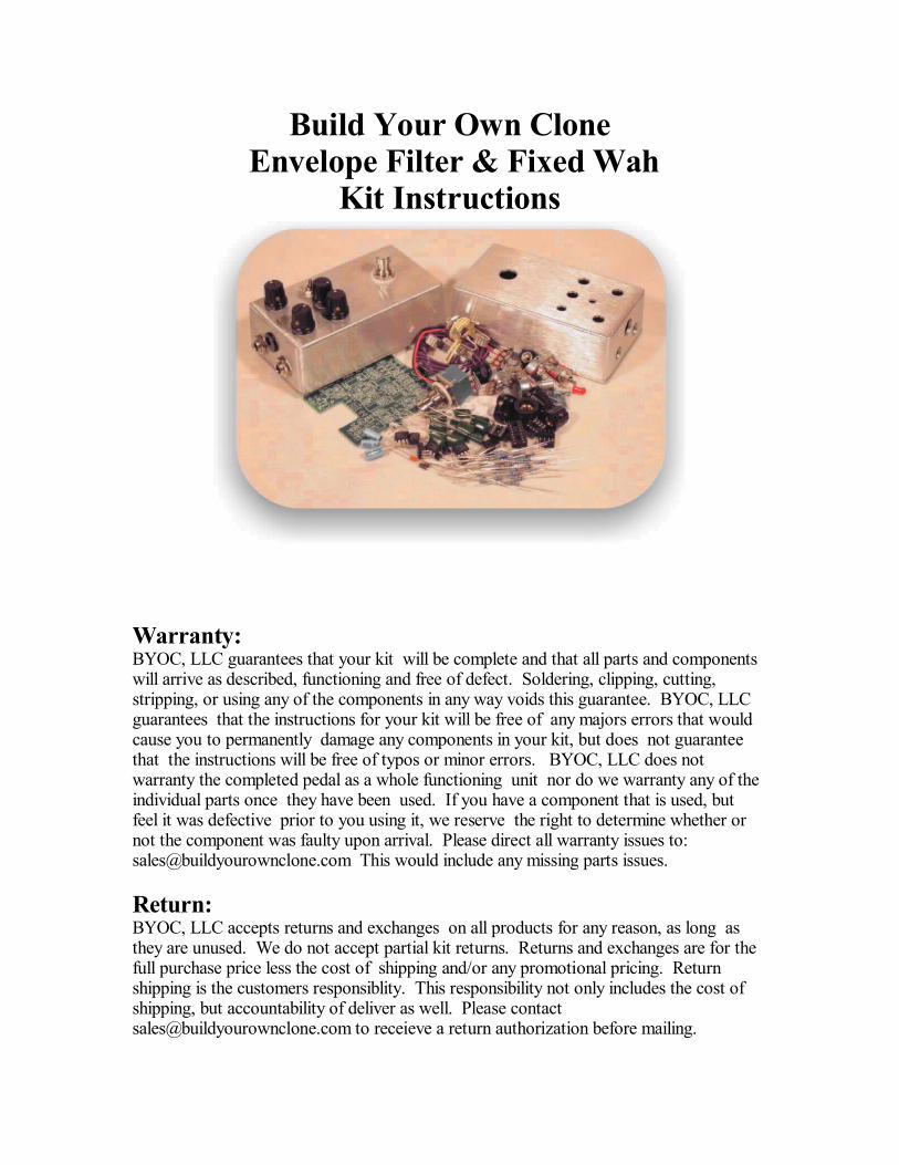
Build Your Own Clone Envelope Filter & Fixed Wah
Kit Instructions
Warranty:BYOC, LLC guarantees that your kit will be complete and that all parts and componentswill arrive as described, functioning and free of defect. Soldering, clipping, cutting,stripping, or using any of the components in any way voids this guarantee. BYOC, LLCguarantees that the instructions for your kit will be free of any majors errors that wouldcause you to permanently damage any components in your kit, but does not guaranteethat the instructions will be free of typos or minor errors. BYOC, LLC does notwarranty the completed pedal as a whole functioning unit nor do we warranty any of theindividual parts once they have been used. If you have a component that is used, butfeel it was defective prior to you using it, we reserve the right to determine whether ornot the component was faulty upon arrival. Please direct all warranty issues to:[email protected] This would include any missing parts issues.
Return:BYOC, LLC accepts returns and exchanges on all products for any reason, as long asthey are unused. We do not accept partial kit returns. Returns and exchanges are for thefull purchase price less the cost of shipping and/or any promotional pricing. Returnshipping is the customers responsiblity. This responsibility not only includes the cost ofshipping, but accountability of deliver as well. Please [email protected] to receieve a return authorization before mailing.
Tech Support:BYOC, LLC makes no promises or guarantees that you will sucessfully complete
your kit in a satisfactory mannor. Nor does BYOC, LLC promise or guarantee that youwill receive any technical support. Purchasing a product from BYOC, LLC does notentitle you to any amount of technical support. BYOC, LLC does not promise orguarantee that any technical support you may receive will be able to resolve any or allissues you may be experiencing.
That being said, we will do our best to help you as much as we can. Ourphilosophy at BYOC is that we will help you only as much as you are willing to helpyourself. We have a wonderful and friendly DIY discussion forum with an entire sectiondevoted to the technical support and modifications of BYOC kits.www.buildyourownclone.com/board
When posting a tech support thread on the BYOC forum, please post it in thecorrect lounge, and please title your thread appropriately. If everyone titles their threadsHELP! , then it makes it impossible for the people who are helping you to keep track of
your progress. A very brief discription of your specific problem will do. It will also makeit easier to see if someone else is having or has had the same problem as you. Thequestion you are about to ask may already be answered. Here are a list of things that youshould include in the body of your tech support thread:1. A detailed explanation of what the problem is. (not just, It doesn t work, help )2. Pic of the top side of your PCB.3. Pic of the underside of your PCB.4. Pic that clearly shows your footswitch/jack wiring and the wires going to the PCB5. A pic that clearly shows your wiring going from the PCB to the pots and any otherswitches(only if your kit has non-PC mounted pots and switches)6. Is bypass working?7. Does the LED come on?8. If you answer yes to 6 and 7, what does the pedal do when it is "on"?9. Battery or adapter.(if battery, is it good? If adapter, what type?)
Also, please only post pics that are in focus. You're only wasting both parties'time if you post out of focus, low res pics from your cell phone.
Revision Notes:Rev 1.0 - Error in PCB that causes bypass tone loss. The circuit output and off-boardwiring to the out jack are connected.Rev 1.1 - no known errors
For older envelope filter kit instructions go to:www.buildyourownclone.com/oldfilter.pdf
Copyrights:All material in this document is copyrighted 2010 by BYOC, LLC
ENVELOPE FILTER & FIXED WAHKIT
INSTRUCTION INDEX
PCB fix (rev1.0 only).................................................page 4
Parts Checklist .............. .....page 5 - 6
Populating the Circuit Board ...................page 7 - 15
Main PCB Assembly .........................................page 16 - 18
Wiring........................................................................page 19 - 22
Installing the IC's and Finishing Up.......................page 23
Operation Overview.................................................page 24 - 25
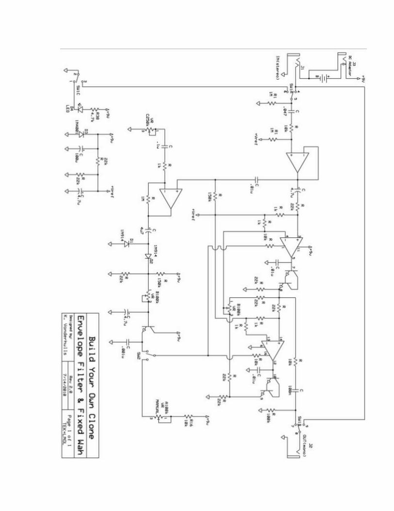
Schematic...................................................................page 26 - 27
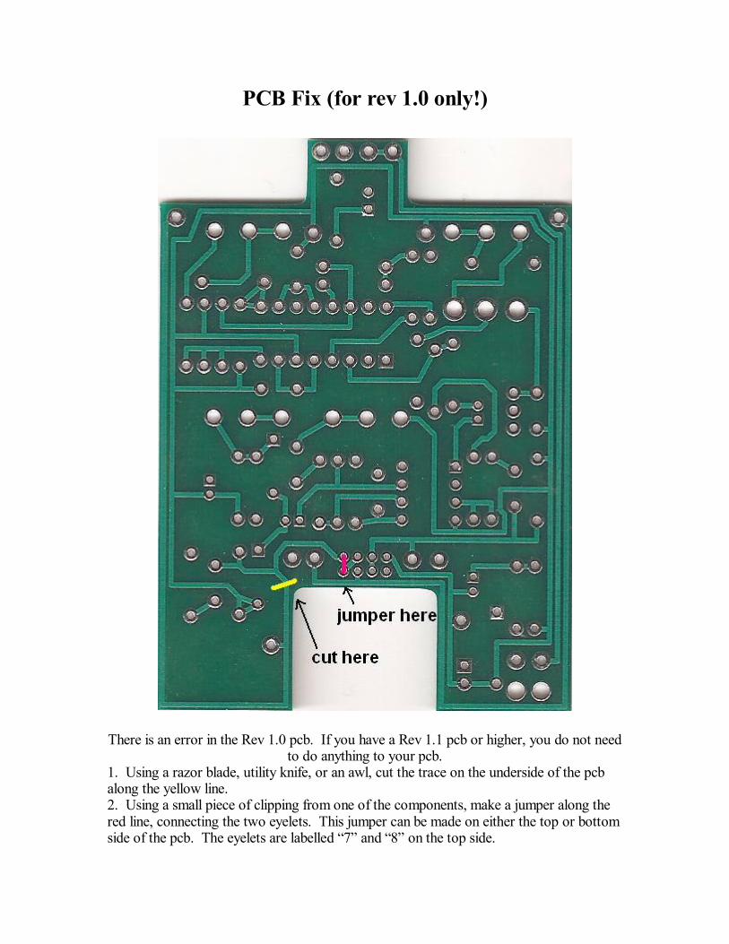
PCB Fix (for rev 1.0 only!)
There is an error in the Rev 1.0 pcb. If you have a Rev 1.1 pcb or higher, you do not needto do anything to your pcb.
1. Using a razor blade, utility knife, or an awl, cut the trace on the underside of the pcbalong the yellow line.2. Using a small piece of clipping from one of the components, make a jumper along thered line, connecting the two eyelets. This jumper can be made on either the top or bottomside of the pcb. The eyelets are labelled 7 and 8 on the top side.
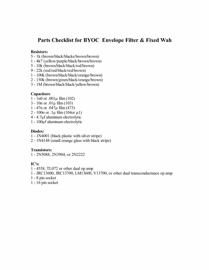
Parts Checklist for BYOC Envelope Filter & Fixed Wah
Resistors:5 - 1k (brown/black/blacke/brown/brown)1 - 4k7 (yellow/purple/black/brown/brown)5 - 10k (brown/black/black/red/brown)9 - 22k (red/red/black/red/brown)1 - 100k (brown/black/black/orange/brown)2 - 150k (brown/green/black/orange/brown)3 - 1M (brown/black/black/yellow/brown)
Capacitors:1 - 1n0 or .001µ film (102)3 - 10n or .01µ film (103)1 - 47n or .047µ film (473)2 - 100n or .1µ film (104or µ1)4 - 4.7µf aluminum electrolytic1 - 100µf aluminum electrolytic
Diodes:1 - 1N4001 (black plastic with silver stripe)2 - 1N4148 (small orange glass with black stripe)
Transistors:1 - 2N5088, 2N3904, or 2N2222
IC's:1 - 4558, TL072 or other dual op amp1 - JRC13600, JRC13700, LM13600, V13700, or other dual transconductance op amp1 - 8 pin socket1 - 16 pin socket
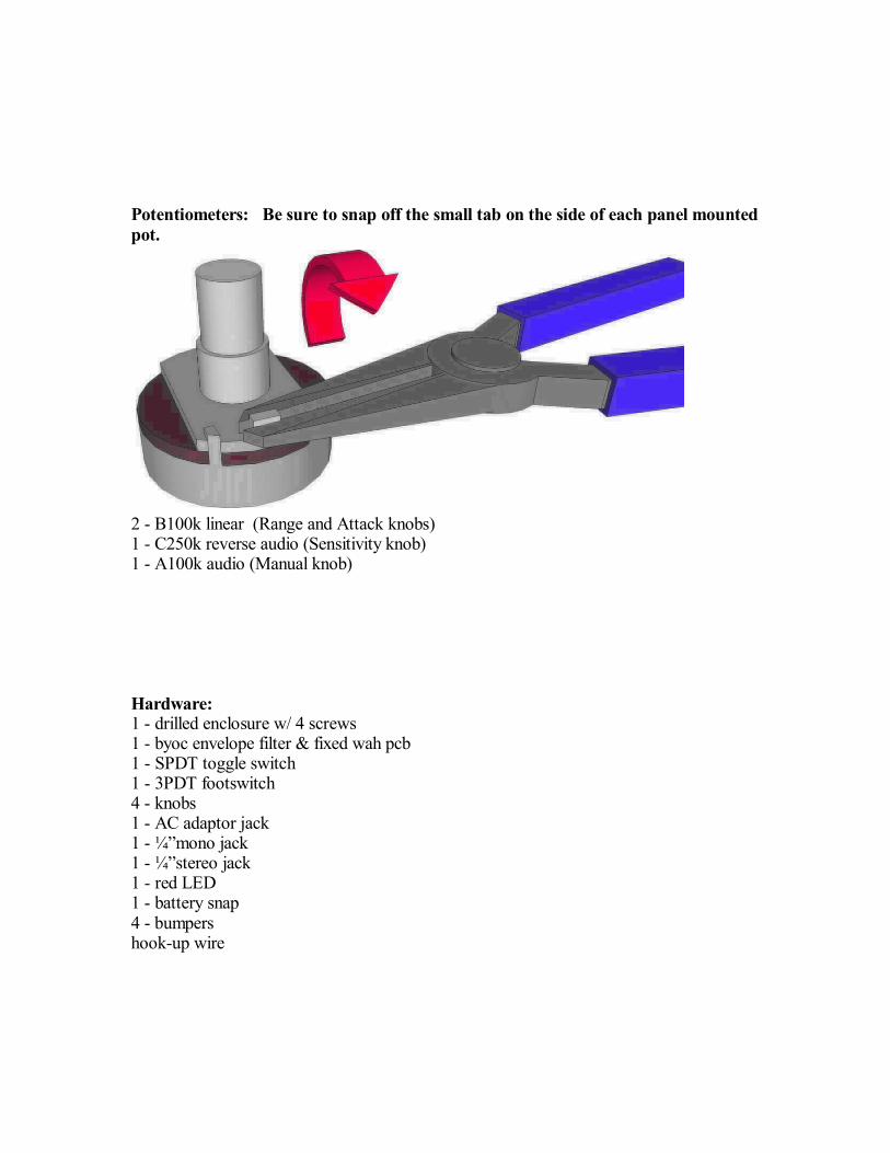
Potentiometers: Be sure to snap off the small tab on the side of each panel mountedpot.
2 - B100k linear (Range and Attack knobs)1 - C250k reverse audio (Sensitivity knob)1 - A100k audio (Manual knob)
Hardware:1 - drilled enclosure w/ 4 screws1 - byoc envelope filter & fixed wah pcb1 - SPDT toggle switch1 - 3PDT footswitch4 - knobs1 - AC adaptor jack1 - ¼ mono jack1 - ¼ stereo jack1 - red LED1 - battery snap4 - bumpershook-up wire
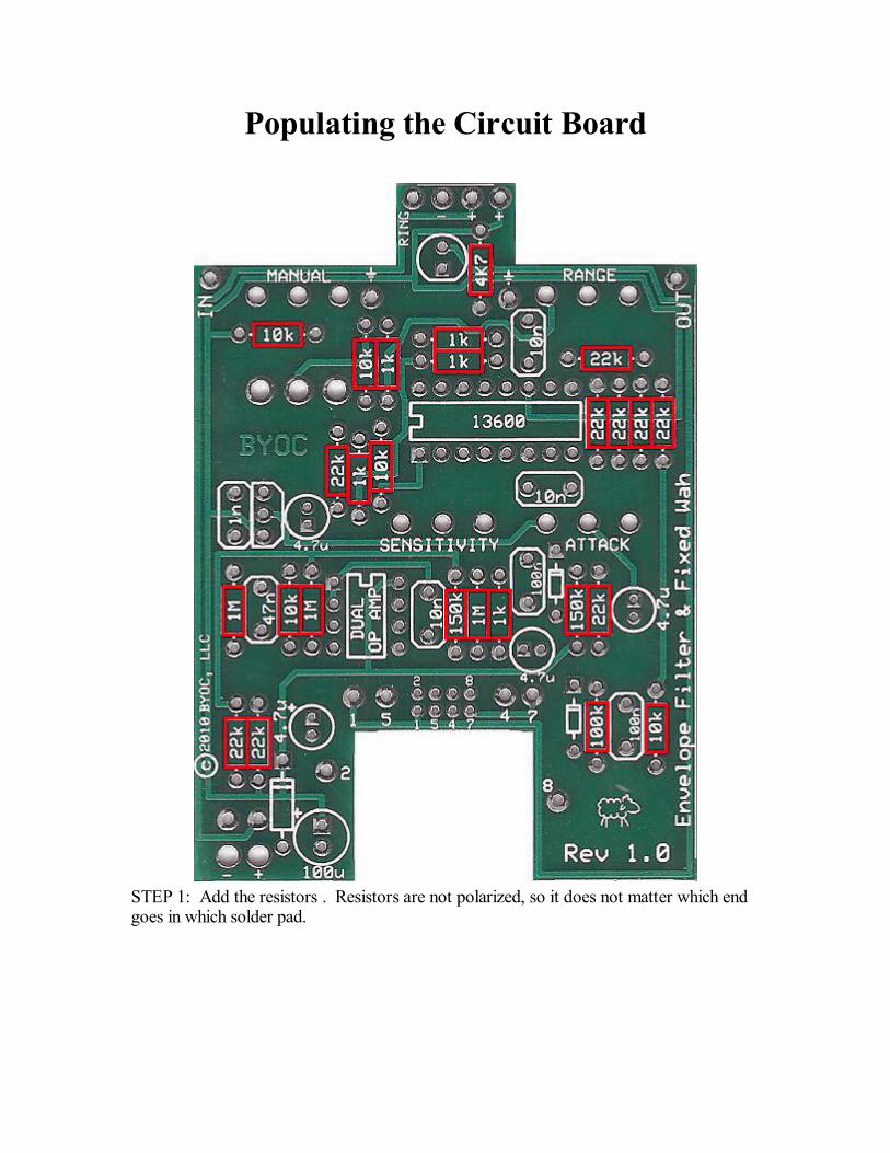
Populating the Circuit Board
STEP 1: Add the resistors . Resistors are not polarized, so it does not matter which endgoes in which solder pad.
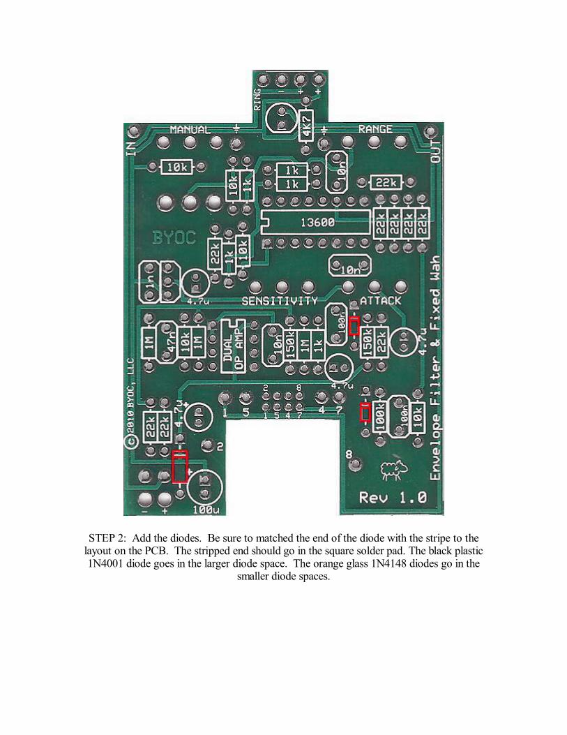
STEP 2: Add the diodes. Be sure to matched the end of the diode with the stripe to thelayout on the PCB. The stripped end should go in the square solder pad. The black plastic1N4001 diode goes in the larger diode space. The orange glass 1N4148 diodes go in the
smaller diode spaces.
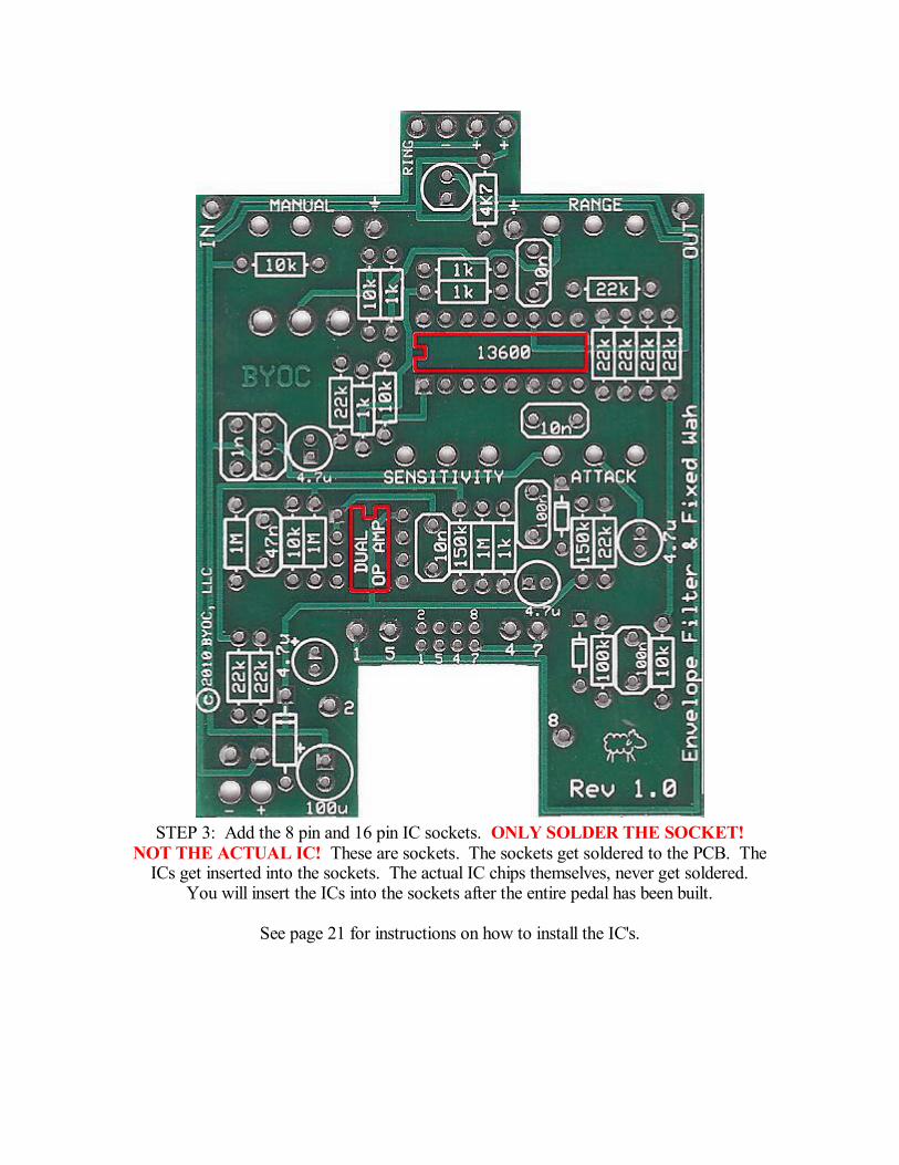
STEP 3: Add the 8 pin and 16 pin IC sockets. ONLY SOLDER THE SOCKET!NOT THE ACTUAL IC! These are sockets. The sockets get soldered to the PCB. The
ICs get inserted into the sockets. The actual IC chips themselves, never get soldered.You will insert the ICs into the sockets after the entire pedal has been built.
See page 21 for instructions on how to install the IC's.
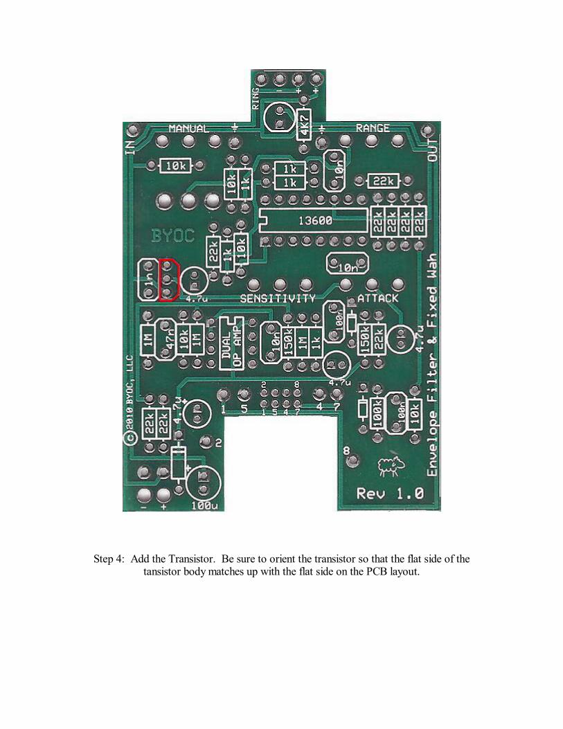
Step 4: Add the Transistor. Be sure to orient the transistor so that the flat side of thetansistor body matches up with the flat side on the PCB layout.
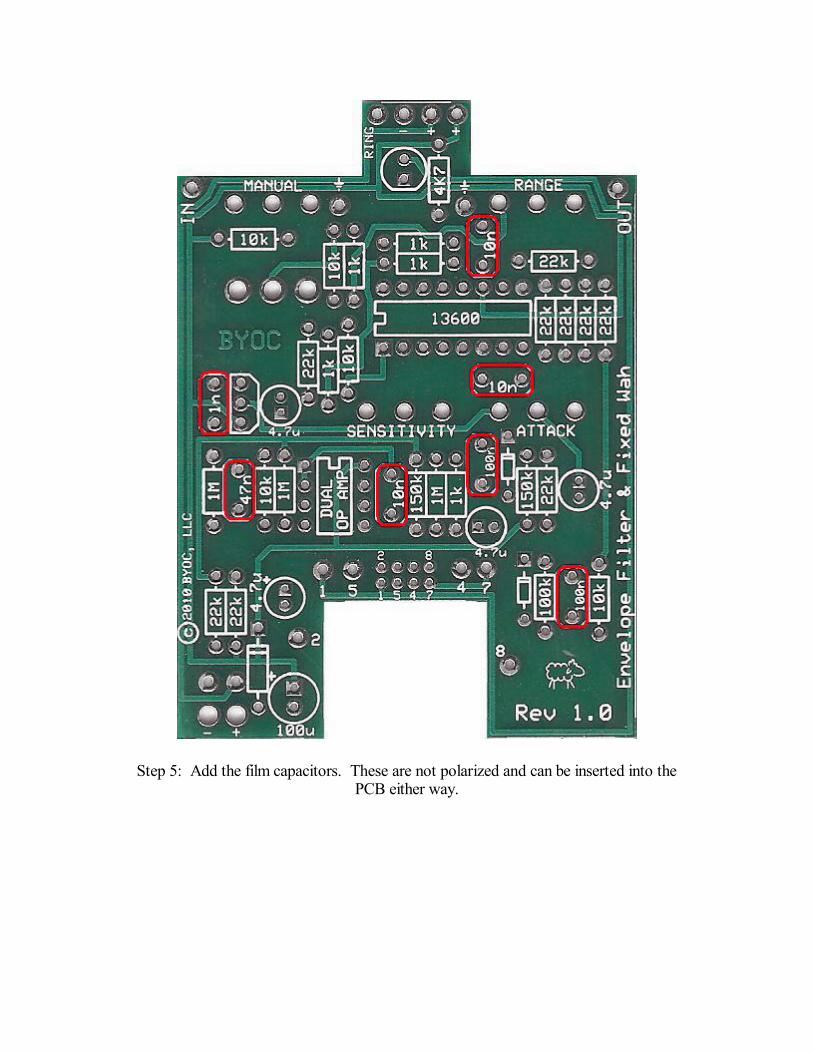
Step 5: Add the film capacitors. These are not polarized and can be inserted into thePCB either way.
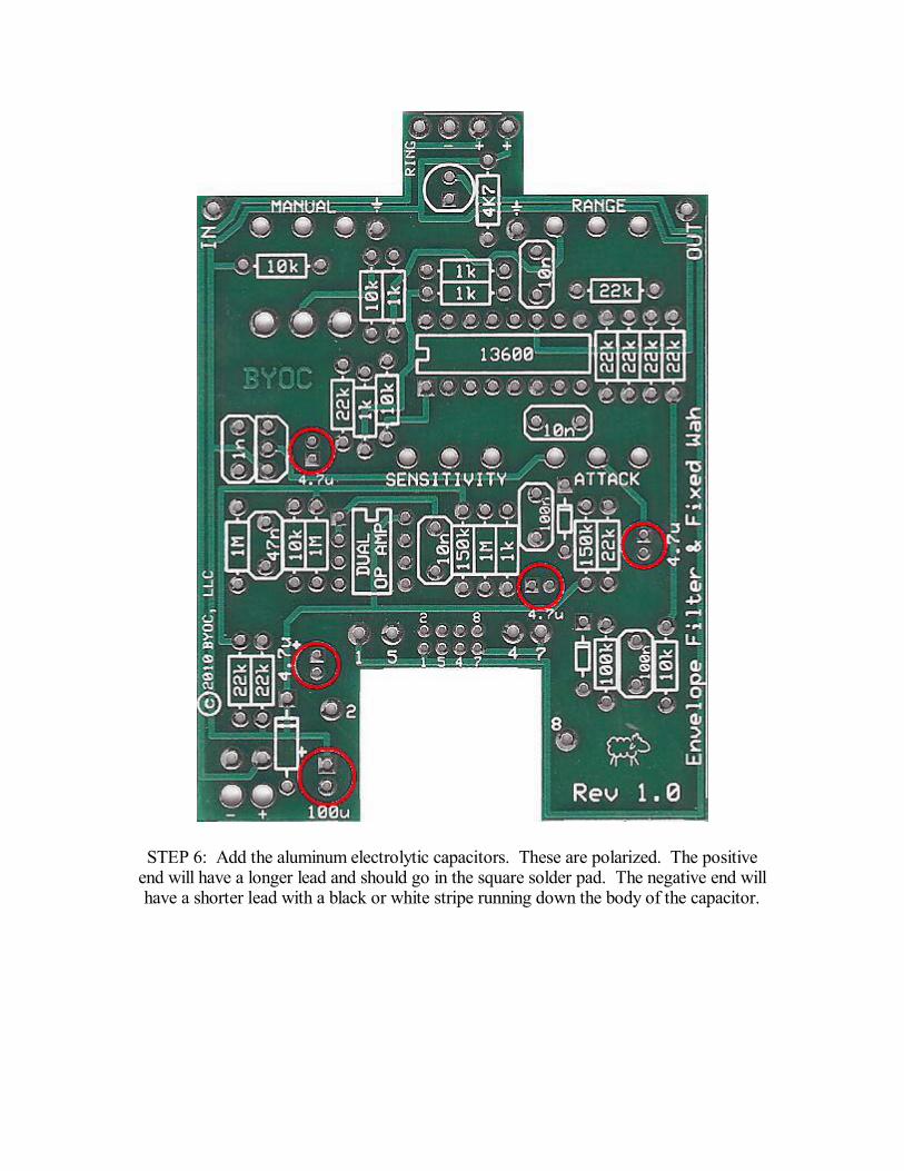
STEP 6: Add the aluminum electrolytic capacitors. These are polarized. The positiveend will have a longer lead and should go in the square solder pad. The negative end willhave a shorter lead with a black or white stripe running down the body of the capacitor.
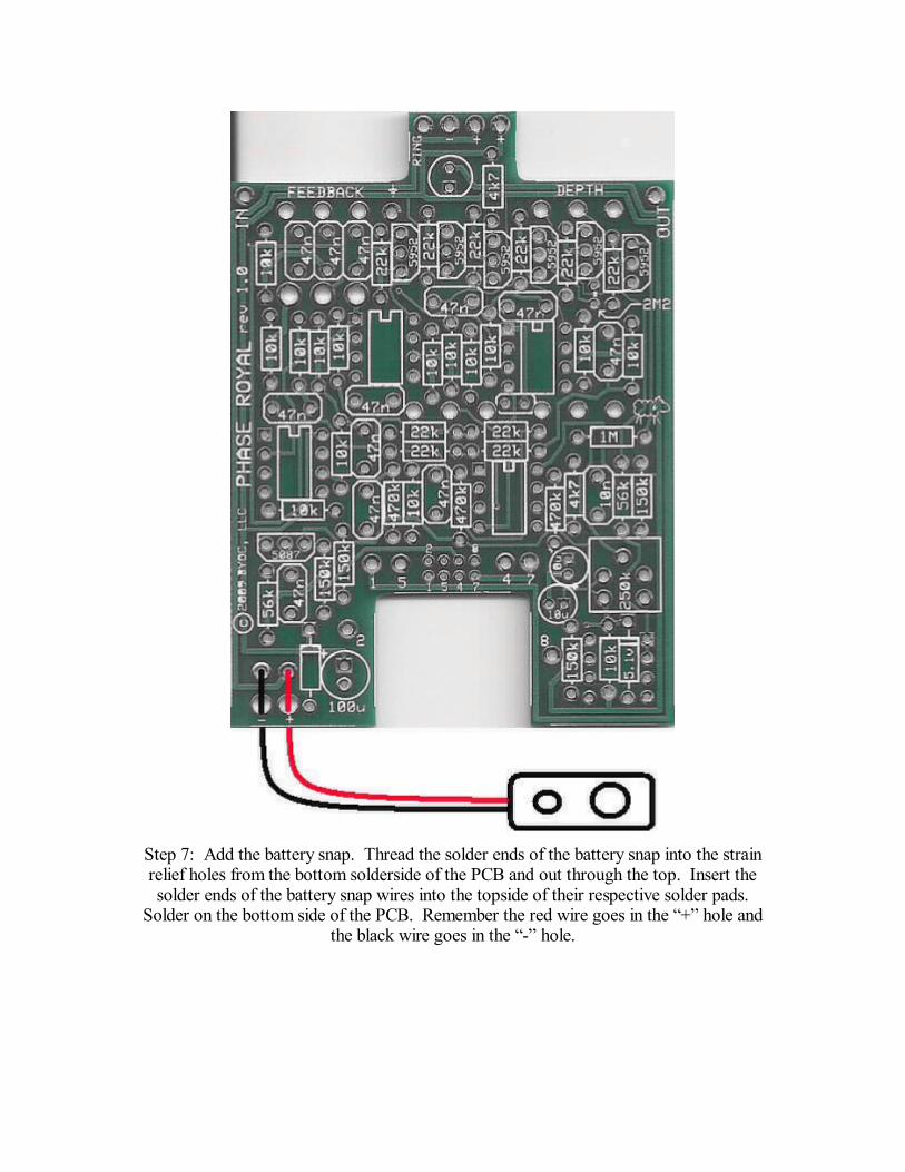
Step 7: Add the battery snap. Thread the solder ends of the battery snap into the strainrelief holes from the bottom solderside of the PCB and out through the top. Insert thesolder ends of the battery snap wires into the topside of their respective solder pads.
Solder on the bottom side of the PCB. Remember the red wire goes in the + hole andthe black wire goes in the - hole.
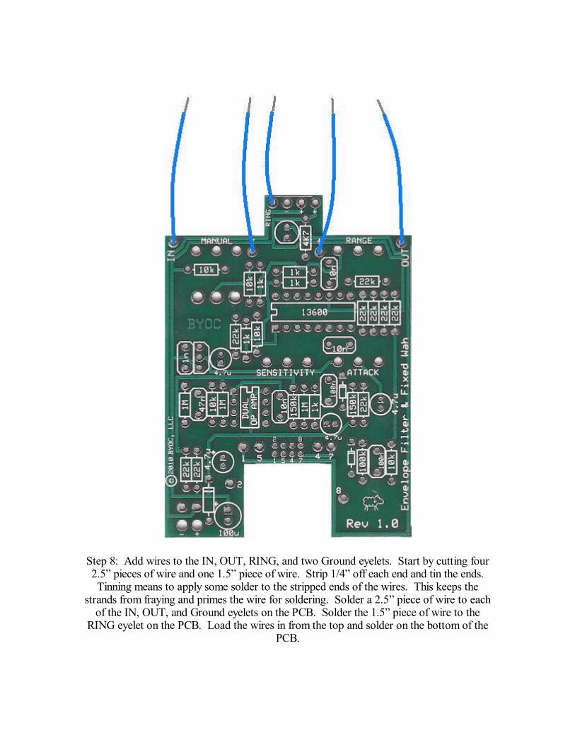
Step 8: Add wires to the IN, OUT, RING, and two Ground eyelets. Start by cutting four2.5 pieces of wire and one 1.5 piece of wire. Strip 1/4 off each end and tin the ends.Tinning means to apply some solder to the stripped ends of the wires. This keeps the
strands from fraying and primes the wire for soldering. Solder a 2.5 piece of wire to eachof the IN, OUT, and Ground eyelets on the PCB. Solder the 1.5 piece of wire to the
RING eyelet on the PCB. Load the wires in from the top and solder on the bottom of thePCB.
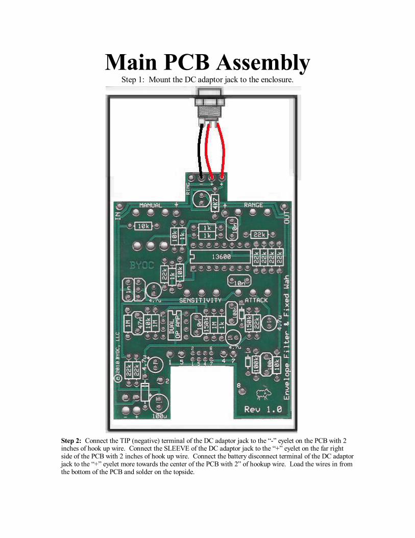
Main PCB AssemblyStep 1: Mount the DC adaptor jack to the enclosure.
Step 2: Connect the TIP (negative) terminal of the DC adaptor jack to the - eyelet on the PCB with 2inches of hook up wire. Connect the SLEEVE of the DC adaptor jack to the + eyelet on the far rightside of the PCB with 2 inches of hook up wire. Connect the battery disconnect terminal of the DC adaptorjack to the + eyelet more towards the center of the PCB with 2 of hookup wire. Load the wires in fromthe bottom of the PCB and solder on the topside.
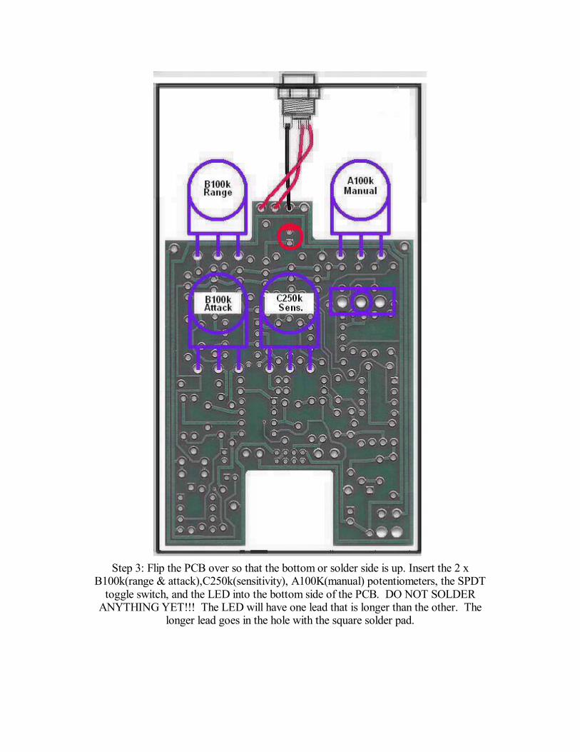
Step 3: Flip the PCB over so that the bottom or solder side is up. Insert the 2 xB100k(range & attack),C250k(sensitivity), A100K(manual) potentiometers, the SPDT
toggle switch, and the LED into the bottom side of the PCB. DO NOT SOLDERANYTHING YET!!! The LED will have one lead that is longer than the other. The
longer lead goes in the hole with the square solder pad.
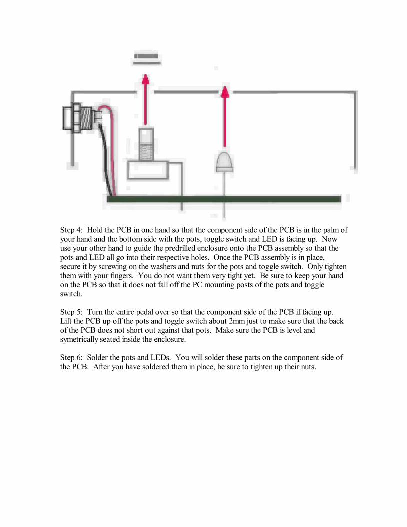
Step 4: Hold the PCB in one hand so that the component side of the PCB is in the palm ofyour hand and the bottom side with the pots, toggle switch and LED is facing up. Nowuse your other hand to guide the predrilled enclosure onto the PCB assembly so that thepots and LED all go into their respective holes. Once the PCB assembly is in place,secure it by screwing on the washers and nuts for the pots and toggle switch. Only tightenthem with your fingers. You do not want them very tight yet. Be sure to keep your handon the PCB so that it does not fall off the PC mounting posts of the pots and toggleswitch.
Step 5: Turn the entire pedal over so that the component side of the PCB if facing up.Lift the PCB up off the pots and toggle switch about 2mm just to make sure that the backof the PCB does not short out against that pots. Make sure the PCB is level andsymetrically seated inside the enclosure.
Step 6: Solder the pots and LEDs. You will solder these parts on the component side ofthe PCB. After you have soldered them in place, be sure to tighten up their nuts.
Wiring
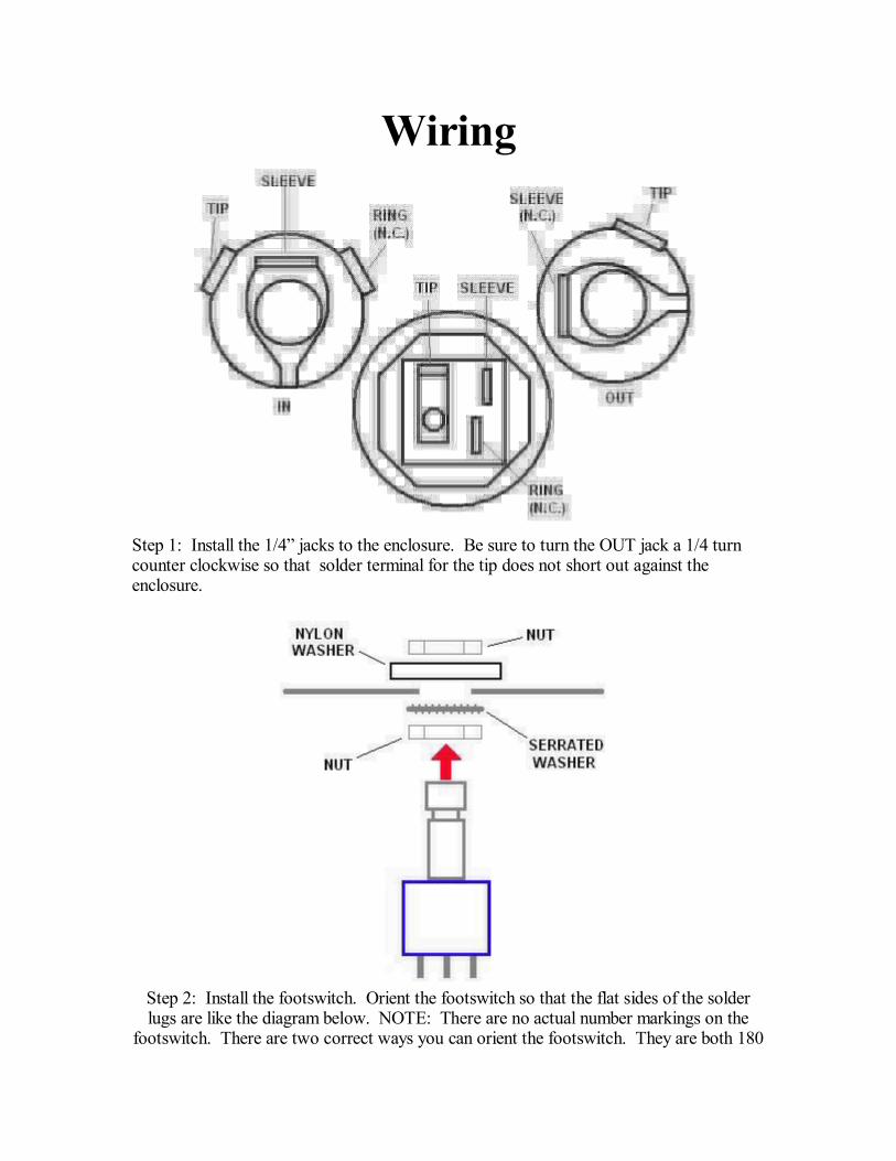
Step 1: Install the 1/4 jacks to the enclosure. Be sure to turn the OUT jack a 1/4 turncounter clockwise so that solder terminal for the tip does not short out against theenclosure.
Step 2: Install the footswitch. Orient the footswitch so that the flat sides of the solderlugs are like the diagram below. NOTE: There are no actual number markings on the
footswitch. There are two correct ways you can orient the footswitch. They are both 180

degrees of each other. Either way is fine. It does not matter as long as the flat sides ofthe solder lugs are running horizontal, not vertical.
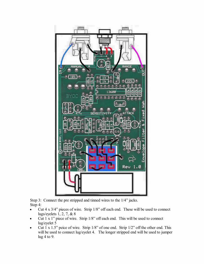
Step 3: Connect the pre stripped and tinned wires to the 1/4 jacks.Step 4:· Cut 4 x 3/4 pieces of wire. Strip 1/8 off each end. These will be used to connect
lugs/eyelets 1, 2, 7, & 8· Cut 1 x 1 piece of wire. Strip 1/8 off each end. This will be used to connect
lug/eyelet 5· Cut 1 x 1.5 peice of wire. Strip 1/8 of one end. Strip 1/2 off the other end. This
will be used to connect lug/eyelet 4. The longer stripped end will be used to jumperlug 4 to 9.
· Cut 3 x 2 pieces of wire. Strip 1/4 off each end. These will be used to connect thetip and sleeve of the IN jack and the tip of the OUT jack to the PCB.
· Cut 1 x 1.5 peice of wire. Strip 1/4 off each end. This will be used to connect thering of the IN jack to the ring eyelet on the PCB.
Step 5: Solder one end of the pre-cut and pre-stripped wires to the footswitch.
Step 6: Insert the other remaining ends of the pre-cut and pre-stripped wires into thetopside of the PCB and solder. You can can solder these on the topside as well. It iseasier this way, but you may burn a small amount of the PVC coating on the wires. This ispurely asthetic and won't damage the wires in anyway. But you can avoid this byremoving the PCB assembly and footswitch from the enclosure entirely (the PCBassembly will still be attached to the enclosure via the DC jack wiring) so that you haveaccess to solder the underside of the PCB.
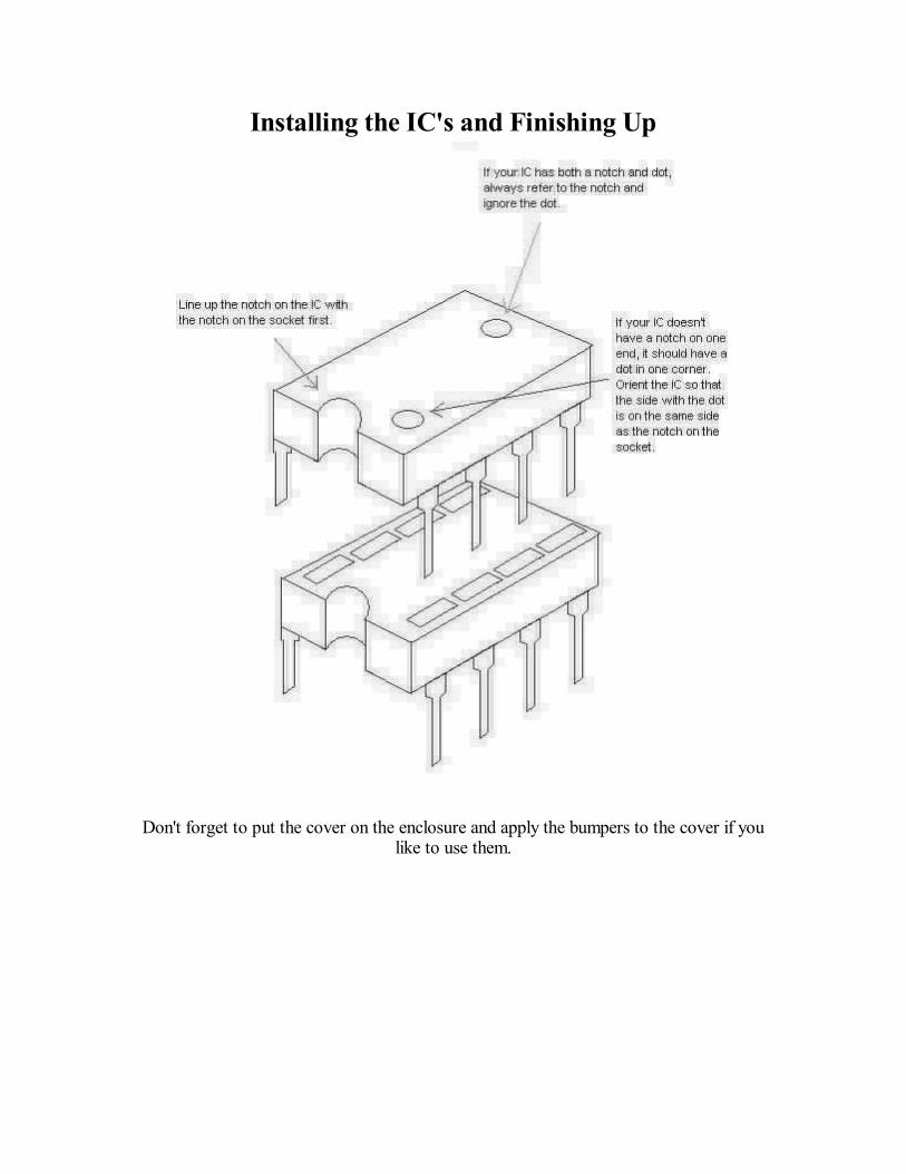
Installing the IC's and Finishing Up
Don't forget to put the cover on the enclosure and apply the bumpers to the cover if youlike to use them.
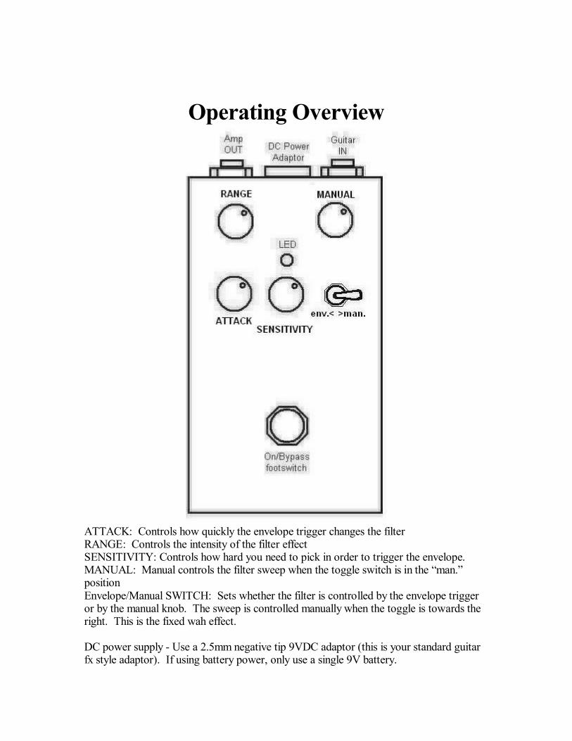
Operating Overview
ATTACK: Controls how quickly the envelope trigger changes the filterRANGE: Controls the intensity of the filter effectSENSITIVITY: Controls how hard you need to pick in order to trigger the envelope.MANUAL: Manual controls the filter sweep when the toggle switch is in the man.positionEnvelope/Manual SWITCH: Sets whether the filter is controlled by the envelope triggeror by the manual knob. The sweep is controlled manually when the toggle is towards theright. This is the fixed wah effect.
DC power supply - Use a 2.5mm negative tip 9VDC adaptor (this is your standard guitarfx style adaptor). If using battery power, only use a single 9V battery.

Current Draw - 5.5mA
Input Impedance - 1M ohms
Output Impedance - 100k ohms

Please visithttp://buildyourownclone.com/board
for any technical support
copyright 2010B.Y.O.C., LLC