building a mission-critical communications network
TRANSCRIPT

Building a Mission-critical communications network Network transformation for IP CCTV
A P P L I C A T I O N N O T E

Table of contents
Introduction / 1
IP CCTV system architecture / 2
The Alcatel-Lucent mission-critical network for IP CCTV / 3
Building the Backhaul Network for CCTV Backhaul / 4
Ethernet pseudowire for cost-effective access with redundancy / 6
Delivering video stream in the core network / 8
Delivering mobile video stream / 9
The Alcatel-Lucent advantage / 10
Summary / 10
Abbreviations / 10
IntroductionIndustries and governments have long used closed-circuit television (CCTV) systems in their mission-critical operations to monitor sites and industrial processes, as well as protect assets and human lives. The application transmits video signal from cameras mounted in areas that need monitoring, such as rail and metro stations; airports and ports facilities; oil rigs and pipelines; utility substations and other remote stations. Today, with public safety being a top concern, it is no longer just the operators who need to view the video feeds. Other government agencies, such as municipal police, regional and even national agencies also need to increase situational awareness when responding to incidents and use video analytics applications for incident investigations.
CCTV systems have evolved from purely analog to today’s IP-based digital systems, which comprise the following major components:
• IP video cameras: installed at strategic remote locations to encode, compress and packetize video signals and send the IP packets across the network, typically over an Ethernet port
¬ Many older-generation analog cameras remain deployed, retrofitted with an external IP encoder
• Video management systems and storage: dedicated servers and storage that run video management applications for video control and storage; camera management controls, including pan, tilt and zoom; and services for video clients, from which operators can view the video stream and perform analytics, if necessary
• Video clients: computers capable of accessing services from video servers, such as live feed from a specific camera or a section of archived footage; there can be multiple video clients, one in the network operations center (NOC) and others in control and command center, each watching the same video streams at the same time
Carrying the exploding volume of IP video traffic, however, along with traffic from other operational applications, such as SCADA and signaling, as well as IT applications including e-mail and other enterprise applications, has become a challenge for networks that still use traditional best-effort IP and Ethernet networks. If not designed and built with the right architecture and technology, adding video traffic into an unprepared network will severely impact all services on the network.
It is, therefore, crucial for operators to select a network technology and architecture that can address their CCTV requirements. They need a reliable, always-on, highly resilient solution that can handle many high-quality video streams, and accommodate the convergence of video, voice, operational real-time and best-effort data traffic with deterministic quality of service (QoS). The network architecture must also be optimized to handle the current traffic volume and future growth.
Alcatel-Lucent has an advanced, mission-critical communications solution that can meet the requirements for deterministic delivery of IP video surveillance traffic and concurrent support for other critical operations applications, including voice traffic, on a single converged network.
1
Building a Mission-critical communications network
Alcatel-Lucent Application Note

IP CCTV system architectureAs outlined in the introduction, extensive deployment of video surveillance places heavy demands on network resources. The mission-critical network must, therefore, be able to support the high bandwidth required by video traffic efficiently, with multiple stringent QoS levels. The bandwidth required for video surveillance traffic is affected by many factors, including:
• Number of IP cameras in the network
• Number of existing analog cameras to migrate to the new IP network
• Frame rate and size
• Level of motion
• Light intensity
• Video compression algorithm
• Optional audio channels
• Video camera remote control
• Number of control rooms in the network
• Number of storage locations in the network
Although compromises can be made to minimize the required bandwidth, there is increasing pressure to ensure video captured is high enough quality for security and protection purposes. For example, an image must be sufficiently clear for investigative purposes and for submission as court evidence. Also, as video analytics software is becoming an indispensable tool for automated anomaly detection, it requires high-quality video to work properly. High-quality video may require several Mb/s per stream. In addition, the video surveillance network must also be able to handle the jitter and latency requirements of video traffic for real-time monitoring, as situations arise.
A typical CCTV system architecture is show in Figure 1. IP cameras are installed in remote sites. Video signals, encoded in IP packets, are backhauled to the video control and storage system in the NOC. There are also video clients for operators to monitor and analyze video streams. As in most mission-critical networks, to provide redundancy protection for the equipment as well as for the site (also known as geo-diversity), there is an active NOC and a standby NOC, each with its own set of video systems. In addition, network connectivity is required to allow video clients from other organizations – such as law enforcement control and command centers or municipal emergency centers – to receive video streams for situational awareness when serious incidents occur. All the locations are connected by a core network that transports video traffic with resiliency and high QoS.
Figure 1. Typical IP video surveillance system architecture
Municipalemergency center
Sites undersurveillance
Video management system
ActiveNOC
Video client IP cameraAnalog camera withexternal encoder
StandbyNOC
Policecommand center
2
Building a Mission-critical communications network
Alcatel-Lucent Application Note
Depending on the CCTV system deployed and its configuration, IP video traffic can be carried in unicast or multicast IP packets. IP multicast packets are encoded with a multicast group address in the IP header’s Destination Address field. The IP multicast address is distinguished from its unicast peer by the leading addressing bits of 0b11101. When using IP unicast technology, the video source must send individual streams to each recipient (also called the listener in IP multicast terminology). This multiplies the amount of bandwidth required in the network. IP multicast can improve bandwidth efficiency by allowing the source to send one stream and use the network to replicate the stream, as required.
The Alcatel-Lucent mission-critical network for IP CCTVIP and Ethernet networks have grown significantly in recent years, but they often lack the necessary ability to deliver traffic from multiple critical applications that require deterministic QoS levels other than best effort, and SONET/SDH-like resiliency. Traditional IP and Ethernet networks, limited by routing convergence speeds and spanning tree protocol-based recovery, also lack the ability to recover from network failures fast enough to guarantee end-to-end delivery without degrading performance.
The Alcatel-Lucent mission-critical communications network adopts a service-oriented approach that focuses on service scalability and quality, per-service operations, administration and maintenance (OAM) under the supervision of the service-aware network manager, the Alcatel-Lucent 5620 Service Aware Manager (SAM), plus advanced, flexible, hierarchical QoS. With a service-aware infrastructure, network operators can tailor traffic priority, parameters, and path for each application, so mission-critical applications always have enough committed bandwidth to meet peak requirements and non-critical applications have sufficient bandwidth to meet an acceptable pre-engineered performance level.
The components of the mission-critical network include the Alcatel-Lucent 7750 Service Router (SR)2 product family for core networks, the 7705 Service Aggregation Router (SAR)3, and the 7210 Service Access Switch (SAS)4 for aggregation and access connectivity. The Alcatel-Lucent IP/MPLS service routing products are also available in compact, ruggedized and full outdoor form factors, so operators can extend their network to the most remote locations, in rough terrain, with unparalleled reliability.
The administration and management of the Alcatel-Lucent IP/MPLS network is handled by the 5620 SAM5, which simplifies and automates routine tasks while facilitating the introduction and maintenance of new services.
The Alcatel-Lucent mission-critical network has been successfully deployed in industries, governments, and enterprises for mission- and business-critical voice, data and video services. The solution was designed to deliver differentiated multiservice to users, while maintaining QoS for each type of application. This differentiated multiservice capability is crucial for supporting video surveillance systems, because it enables the delivery of thousands of video streams, along with other data and voice applications simultaneously, without performance degradation. This is made possible through
1 For details of IP multicast address assignments, please see IETF RFC5771 (http://tools.ietf.org/html/rfc5771)2 http://www.alcatel-lucent.com/products/7750-service-router3 http://www.alcatel-lucent.com/products/7705-service-aggregation-router4 http://www.alcatel-lucent.com/products/7210-service-access-switch5 http://www.alcatel-lucent.com/products/5620-service-aware-manager-details
3
Building a Mission-critical communications network
Alcatel-Lucent Application Note

a comprehensive set of QoS and traffic-engineering capabilities to meet the stringent delay and jitter requirements of IP video traffic. This capability is especially important if the network is being used to deliver a multitude of other services with different characteristics. The Alcatel-Lucent 7750 SR product family, the 7210 SAS and the 7705 SAR have the traffic-management capabilities to meet these QoS requirements.
The essential attributes of a QoS system capable of providing this level of service include:
• Rich, wire-rate packet classification at Layers 2, 3 and 4
• Fine-grained range of packet priorities, each with an associated service queue, to ensure user traffic is handled in accordance with the required precedence (priority of importance)
• Packet buffering dedicated to traffic in each service queue
• Ingress and egress hierarchical traffic shaping and rate-scheduling, so each service has its own service profile and is segregated from other services for zero cross-impact
Due to the specificity of different mission-critical network operators and the IP video surveillance system chosen, options are available to optimize the network architecture and operations. What follows is a blueprint architecture to illustrate a general solution.
Building the Backhaul Network for CCTV BackhaulA video surveillance system can consist of thousands of high-quality video cameras, each generating an IP video stream. These video streams can consume bandwidth at rates of up to several Mb/s, which must be transported in real time to multiple locations for multiple listeners. To optimize the network architecture, it is important to understand the traffic flow patterns from the video camera to all the video clients in the network.
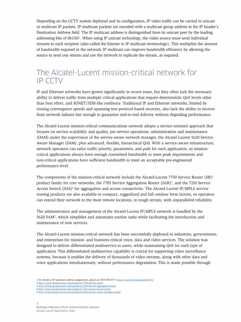
While the actual network design varies depending on each network operator’s requirement and topology constraints, this application note attempts to build a blueprint architecture (Figure 2) as a reference network model. The network can be divided into the backhaul network connecting remote sites with the NOCs and the core network, which enables communications among the NOCs and other video client locations.
In this blueprint architecture, individual video cameras installed at remote sites continuously stream video traffic traversing the mission-critical backhaul network to the video manage-ment system in the NOC. A few other entities, such as municipal governments and public safety organizations will also be interested in viewing the streams from time to time, particularly when incidents occur and a response team needs to be dispatched. Connectivity to those command centers is usually provided by the core network.
This flow pattern is very different from what is seen in a residential triple-play network delivering IPTV service to home users, in which the video source is in the core and delivers traffic to many subscribers at the outer access network. Furthermore, the handful of listeners – the operational staff monitoring sites – are typically located in the network core. This is the opposite of an IPTV multicast network, in which the listeners – the television viewers – are situated in multiple locations across various access domains.
4
Building a Mission-critical communications network
Alcatel-Lucent Application Note
A comparison between IP CCTV traffic and IPTV traffic is found in Table 1.
Figure 2. Video surveillance traffic flow pattern
Public safetycommand center
Active NOC Standby NOC
Municipalemergency center
IP/M
PLS
mis
sion-c
riti
cal
bac
khau
l net
work
IP/M
PLS
core
net
work
Table 1. Traffic flow pattern comparison
TRAFFIC CHARACTERISTIC IPTV IP VIDEO SURVEILLANCE
Number of flows or channels Range from hundreds to thousands Range from hundreds to thousands
Flow duration Depends on viewers Permanent
Number of listeners From thousands to more than tens of thousands
A handful only
Listeners’ location In the network core In the network access
Traffic replication point In the network core In the network access
The seemingly simplest way deliver IP video traffic is to deploy an interior gateway protocol (IGP), such as Intermediate System to Intermediate System (IS-IS) or Open Shortest Path First (OSPF), plus an IP multicast protocol if the video traffic is encoded in IP multicast packets. The most commonly deployed IP multicast protocol is Protocol-Independent Multicast (PIM).6 PIM is responsible for setting up individual multicast trees (one for each IPTV channel) to deliver the traffic from the access network cameras to both the video systems in the NOC and command centers in the network core. Each video camera would be configured to use a different IP multicast address, so would belong to a different multicast group. Internet Group Multicast Protocol (IGMP)7 is used by video clients to signal to the connected router which channel the operator is requesting.
6 PIM can operate in several modes; the most common ones are: • Sparse mode (SM) http://tools.ietf.org/html/rfc460 • Source-specific mode (SSM) http://tools.ietf.org/html/rfc35697 The prevalent IGMP versions are IGMPv2 (https://www.ietf.org/rfc/rfc2236.txt) and IGMPv3 (https://tools.ietf.org/html/rfc3376)
5
Building a Mission-critical communications network
Alcatel-Lucent Application Note

There are, however, challenges associated with this pure IP approach, some of which may cause unacceptable delays when network failures occur. Using PIM multicast trees in the backhaul network to deliver traffic from the camera to the NOC could have a significant negative impact on network resiliency, since the backhaul network topology is usually comprised of rings. IP convergence in a ring topology requires full convergence of all ring nodes before full IP connectivity is restored. Depending on the size of the ring network and the routing table, the convergence time could range from a few seconds to tens of seconds, resulting in an interruption in monitoring.
Even though there is new technology to improve recovery speed, such as IP fast reroute, it cannot be readily applied in a ring topology without having to compute and establish tunnels to bypass failed links in the first place.8 Furthermore, extending PIM to access part of the backhaul network significantly increases operational costs, because it adds to the complexity of the network. Debugging problems in a sparse multicast network is also challenging and can lead to significant periods of downtime.
In light of these issues, a pure IP approach is not considered to be optimal to transport IP CCTV traffic in the backhaul network. An alternate architecture based on Ethernet pseudowire will now be evaluated.
Ethernet pseudowire for cost-effective access with redundancyEthernet pseudowire9 (PW) is an IP/MPLS-based point-to-point service for carrying Ethernet frames over a MPLS network. It is also known as E-Line service.10 It is ideal for providing point-to-point delivery across an IP/MPLS-based backhaul network (Figure 3).
Figure 3. Ethernet pseudowire over a mission-critical backhaul network
Active NOC
IP/M
PLS
mis
sion-c
riti
cal
bac
khau
l net
work
Ethernetpseudowires
8 http://tools.ietf.org/html/draft-ietf-rtgwg-remote-lfa-089 For details of Ethernet pseudowire, please see IETF RFC4448 (http://tools.ietf.org/html/rfc4448)10 For details of E-line, please see Metro Ethernet Forum Technical Specification MEF 6.1
(http://metroethernetforum.org/PDF_Documents/technical-specifications/MEF6-1.pdf)
6
Building a Mission-critical communications network
Alcatel-Lucent Application Note

Ethernet pseudowire is ideal for mission critical backhaul for the following reasons:
1. As explained in Table 1, video clients that view the streams are located outside the backhaul network; video stream replication is not required in the backhaul network. A simple point-to-point delivery can, therefore, optimize the network architecture and operations
2. Ethernet pseudowire rides over an IP/MPLS network which, by leveraging mechanism such as fast re-route and secondary LSP protection, provides resiliency protection on par with SONET/SDH transport networks. For a more detailed discussion of deploying IP/MPLS for mission-critical networks, please refer to the Alcatel-Lucent Technology Whitepaper “MPLS for Mission-Critical Networks”.11
3. Operators often adopt dual-NOC architectures to provide geo-diversity protection – if a disaster strikes the active NOC site, the operation staff can quickly move to the standby NOC site. Ethernet pseudowire can leverage pseudowire redundancy capability,12 which allows video streams to be automatically switched from the active NOC to the standby NOC. The remote site router has an active and a passive pseudowire connected to the two NOCs (Figure 4). Under normal circumstances, video traffic flows via the active pseudowire to the active NOC. In a disaster scenario, instead of requiring operation staff to manually switch hundreds or thousands of pseudowire wires, all remote site routers switch automatically, usually in under a few seconds.
Figure 4. Dual NOC architecture with pseudowire redundancy
Active NOC
IP/M
PLS
mis
sion-c
riti
cal
bac
khau
l net
work
Active Ethernet pseudowire
Standby NOC
Standby Ethernet pseudowire
Once the traffic reaches the NOC in the core network via the Ethernet pseudowire, it can take advantage of IP multicast for optimal distributions to multiple video clients.
11 http://resources.alcatel-lucent.com/asset/17209712 http://tools.ietf.org/html/rfc6718
7
Building a Mission-critical communications network
Alcatel-Lucent Application Note

Delivering video stream in the core networkAs shown in Table 1, video clients are located in the NOCs and operating centers of other official agencies. Video traffic must, therefore, be replicated in the core network to optimize network bandwidth and resources. There are two prevalent options to replicate video traffic: 1) the video server streams to clients in IP multicast packets and relies on the network to perform replication functions; and 2) the video server replicates the traffic for each client view request and streams individually in IP unicast packets. This blueprint architecture assumes the former.
Figure 5 illustrates the delivery of a video stream from the video camera at the far edge, to video control at the NOC, and subsequently to all requesting clients with IP multicast protocol PIM in source-specific mode PIM-SSM). PIM-SSM is ideal for this architecture, as the source IP addresses of cameras are known in advance. Below are the high-level steps:
1. When a camera is powered up, it streams video to the site access router, which forwards the traffic over the Ethernet pseudowire that reaches the NOC core router, which subsequently forwards the traffic to the video management system.
2. Interested video clients send IGMP requests to the first-hop router. PIM-SSM works best with clients that support IGMPv3. For IGMPv2-only clients, the router can perform translation to IGMPv3.
3. Upon receiving IGMPv3 requests, the router sends PIM message to join the multicast tree, which traces its root back to the NOC router.
4. Once the tree is formed, video traffic will stream to all requesting clients.
Figure 5. Video stream walkthrough in the core network
Public safetycommand center
Active NOC
Municipalemergency center
IP/M
PLS
core
net
work
1a1b
2
2 2
3
3 3
44
44
4 4
8
Building a Mission-critical communications network
Alcatel-Lucent Application Note

Delivering mobile video streamAs fourth generation (4G) wireless technology – also known as Long Term Evolution (LTE) – is evaluated and adopted by mission-critical operators, video traffic could now travel over 4G wireless links to 4G base stations, known as enhanced Node B (eNB). A potential use case is a public safety organization deploying a mobile command and control center, typically in a truck, when responding to a serious incident (Figure 6).
Figure 6. Backhauling mobile video traffic
Public safetycommand center
Active NOC Standby NOC
Municipalemergency center
IP/M
PLS
mis
sion-c
riti
cal
bac
khau
l net
work
IP/M
PLS
core
net
work
EPC
eNodeB
4
4
2
2
3
1
The blueprint architecture can readily be applied to support this use case, as follows:
1. IP video traffic is transmitted over LTE airwaves, received by the eNB and sent to the IP/MPLS router at the cell site
2. The cell site router sends traffic to the Evolved Packet Core (EPC), the LTE traffic gateway, via the backhaul network and core network
3. After processing the eNB traffic, EPC sends traffic to the NOC router
4. The NOC router then multicast to all video clients
9
Building a Mission-critical communications network
Alcatel-Lucent Application Note

The Alcatel-Lucent advantageAlcatel-Lucent is a world leader in building mission-critical networks. Its unique, comprehensive communications equipment portfolio of IP/MPLS, microwave, optics, and network management enables customers to flexibly build end-to-end managed converged networks. Its wide support of legacy interfaces allows customers to migrate deployed legacy applications smoothly. Coupled with advanced MPLS networking and QoS capabilities, all services can be delivered deterministically, without compromise. The innovative management system for IP/MPLS, microwave and optics layers further optimizes network provisioning and operations.
SummaryOrganizations requiring CCTV must ensure their mission-critical networks are built to support consolidated voice, data and video applications without performance degradation. The networks must be able to scale to accommodate traffic growth, and support advanced QoS to attain deterministic delivery and high resiliency. Adopting a network architecture based on Ethernet pseudowire backhaul into an IP multicast core network has been shown to overcome the challenges and meet all necessary requirements.
AbbreviationsCAPEX Capital expenditure
CCTV Closed circuit television
eNB Enhanced Node B
EPC Evolved Packet Core
IGMP Internet Group Management Protocol
IGP Interior Gateway Protocol
IP/MPLS Internet Protocol/Multiprotocol Label Switching
IP-VPN Internet Protocol Virtual Private Network
IS-IS Intermediate System to Intermediate System
IT Information technology
LAN Local area network
LTE Long Term Evolution
MAC Media access control
NOC Network operations center
OAM Operations, administration and maintenance
OPEX Operating expenditure
OSPF Open Shortest Path First
PIM Protocol-Independent Multicast
PIM-SM Protocol-Independent Multicast – Sparse Mode
PIM-SSM Protocol-Independent Multicast – Source Specific Mode
PW Pseudowire
QoS Quality of service
TDM Time-division multiplexing
VPLS Virtual private LAN service
WAN Wide area network
www.alcatel-lucent.com Alcatel, Lucent, Alcatel-Lucent and the Alcatel-Lucent logo are trademarks of Alcatel-Lucent. All other trademarks are the property of their respective owners. The information presented is subject to change without notice. Alcatel-Lucent assumes no responsibility for inaccuracies contained herein. Copyright © 2015 Alcatel-Lucent. All rights reserved. PR1502008788 (March)