building an on30 black bear deck bridge
TRANSCRIPT
7/29/2019 Building an On30 Black Bear Deck Bridge
http://slidepdf.com/reader/full/building-an-on30-black-bear-deck-bridge 1/6
conomics drive the decisions about building bridges on theprototype railroads. If a bridge is deemed necessary and moreeconomical than a large fill, the trestle is the first choice becauseof lower cost and ease of construction. But a deck bridge will be
used if a “long span” bridge is needed or the area is subject to wash-outs
If you find you need to cross such a area on your railroad, I suggestusing the O scale Deck Bridge Kit (DBK-O) from Black Bear ConstructionCo. The main component of the kit is a set of laser cut acrylic construc-tion jigs. The kit allows the building of a deck bridge from five inches(20 scale feet) to seventeen inches (70 scale feet) long. The kit containsa package of materials needed to build the bridge and a full size draw-ing. The jigs can be reused by purchasing more materials.
Before beginning construction, stain all the wood, treat the steel rods with Blacken-It and paint the nut-bolt-washer castings (NBW) and theiron straps. For each iron strap, you need about 7 ⁄ 8" of the .030" x .188”styrene stock enclosed with the materials pack. Our bridge needs 12iron straps. Paint only what you need. The rest of the styrene is used to
shim the braces in the jig while the bridge is being assembled. (Referto Figures 1 and 2 for the names, sizes, and locations of all the bridgemembers.)
Bridge construction has four basic parts:A. Build two identical side panels.B. Determine the spacing between the side panels and build the
end panels.C. Join the side panels together using floor beams and end panels.D. Install the iron rods, beams, braces and stringers.
PART A - BUILDING THE SIDE PANELS
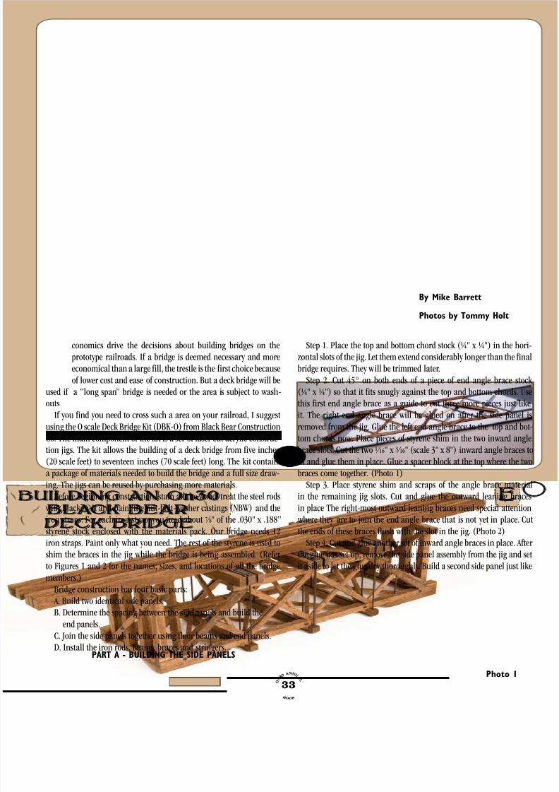
Step 1. Place the top and bottom chord stock (¼" x ¼") in the horzontal slots of the jig. Let them extend considerably longer than the finbridge requires. They will be trimmed later.
Step 2. Cut 45° on both ends of a piece of end angle brace sto(¼" x ¼") so that it fits snugly against the top and bottom chords. Uthis first end angle brace as a guide to cut three more pieces just lik
it. The right end angle brace will be glued on after the side panelremoved from the jig. Glue the left end angle brace to the top and btom chords now. Place pieces of styrene shim in the two inward angbrace slots. Cut the two 1 ⁄ 16" x 3 ⁄ 16" (scale 3" x 8") inward angle bracesfit and glue them in place. Glue a spacer block at the top where the twbraces come together. (Photo 1)
Step 3. Place styrene shim and scraps of the angle brace materin the remaining jig slots. Cut and glue the outward leaning bracin place The right-most outward leaning braces need special attentio where they are to join the end angle brace that is not yet in place. Cthe ends of these braces flush with the slot in the jig. (Photo 2)
Step 4. Cut and glue another set of inward angle braces in place. Aft
the glue has set up, remove the side panel assembly from the jig and sit aside to let the glue dry thoroughly. Build a second side panel just li
O n 3 0
an n u a
l
2 0 0 8 33
By Mike Barrett
Photos by Tommy Holt
Photo 1

7/29/2019 Building an On30 Black Bear Deck Bridge
http://slidepdf.com/reader/full/building-an-on30-black-bear-deck-bridge 2/6
the first. Take one of the extra end angle braces you cut in the beginningand glue it in place at the right end of the side panel assembly. Do thisoutside the jig. Repeat these steps to make two side panel assemblies.(Photo 3)
5. Place the two side panels side by side and mark where the top andbottom chords are to be cut off. Typical cut distances beyond the endangle brace are ¼" (12" scale) for the top chord and 1" (4' scale) for thebottom chord. Ours is cut shorter so the bottom chords do not interfere
with the first trestle bent.6. Cut and glue in place the end stops and side plate shoes, or corbels.
Stack the side panels together. Orient them symmetrically with thebetter side facing out. Mark the panels so you can always keep themoriented the same way.
7. Mark the locations of the lateral tension rods on one of the sidepanel assemblies. Take into account where the end panel is going to belocated. Stack the side panels together and drill the holes for the lateraltension rods in the bottom chords. (Photo 4)
8. The NBW on top of the knee brace rod is located in a notch thatmust be carved into the end angle brace. Drill a hole for the knee bracerod. Carve and counter bore the hole in the end angle brace but do not
yet drill a hole in the bottom chord. Consider skipping this step andeliminating the knee brace rod because of the difficulty in carving thenotch. (Photo 5)
PART B - BUILD THE END PANEL ASSEMBLIES
1. The end panel assemblies set the width of the bridge. The Black Bear jig set includes end panel jigs for standard gauge and narrow gauge. We will use the narrow gauge end panels. The bridge can bemade a little wider than a standard On30/On3 bridge if the location ison a curve.
2. Cut the end panel cap and place in the end panel jig. (Photo 6)3. Determine the length of the end panel posts. This is not as easy as
it seems. Lay one of the side panel assemblies on its side and place apiece of the ¼" x 3 ⁄ 8" (scale 12" x 18") material you will use for the topmain beams along the top chord. Place a piece of ¼" x ¼" (scale 12" x12" end panel top cap material on top of the top main beam material.Place another piece of ¼" x ¼" (scale 12" x 12") end panel post materialsquare to the top main beam. Mark the post where it lines up with thebottom of the bottom chord. Cut the post material at this point. (Note: If the bridge mounts on a stone or concrete abutment rather than a trestlebent, cut the end post at the top of the bottom chord.
4. Construct two end panel assemblies, complete with diagonal bracesand NBW’s.
PART C - JOIN SIDE PANELS USING BEAMS & END PANELS.1. Cut a piece of ¼" x ¼" (scale 12" x 12") bottom beam stock ½" (2
scale feet) longer than the outside of the bridge assembly. Drill holesin the bottom beam that locate vertical tension rods 1 ⁄ 8" (scale 6") oneither side of the top chord and 1 ⁄ 8" from the end of the beam. Build a jigthat consistently locates the tension rod holes near the ends of the topmain beams and the lower beams. Use this jig to drill holes for the ironrods in one piece of the bottom beam material. Trial fit it to make surethe holes are located correctly. When you locate the endmost beams,make sure there is room for the top secondary beams on both sides.
O n 3 0 an n u
a l
2 0 0 8 34
Photo 3
Photo 2
Photo 5
Photo 4

7/29/2019 Building an On30 Black Bear Deck Bridge
http://slidepdf.com/reader/full/building-an-on30-black-bear-deck-bridge 3/6
(Photo 7)2. Install all but the endmost lateral tension rods in both side panels.
Locate the end panels between the side panels and place the assembly upside down on a work surface with parallel lines or a grid pattern.Hold the end panels in place with rubber bands. Be sure to keep the sidepanels upright and parallel. Rotate the end panels out of the way so they don’t interfere with the installation of the top and bottom beams.
3. Place the vertical tension rods in the bottom beams. Place the
beams and rods in their approximate locations. Make sure all the rodsare spaced evenly from the chords and all the beams are parallel. Linethe tension rods up with the brace intersections. Glue the bottom beamsin place against the bottom chords. (Photo 8)
4. Cut the top main beams to the same length as the bottom beams.Use the same hole-drilling jig to drill the vertical tension rod holes inthe top main beams like you did in the bottom beams. Thread the verti-cal tension rods into the holes in the top main beams. Make sure thetension rods and beams are parallel. Glue the top main beams in place.Rubber bands help hold the members in place while you check that they are square. (Photo 9)
PART D - INSTALL THE IRON RODS AND BRACES1. It is now time to install the diagonal bracing, or struts. Start with
the upper bottom diagonal braces. You will probably have to groovethese braces for the lateral tension rods. Notice that the tension rodsmay be easily removed to gain access to the diagonal bracing becausethey are not yet glued in place. (Photo 10)
2. Next, install the lower bottom diagonal braces, the inner diagonalbraces, and the lower top diagonal braces, in that order.
3. Finish building the upper beams by installing a 1 ⁄ 16" x 3 ⁄ 16" (scale3" x 8") spacer against the sides of the top main beams. Before gluingthe spacers in place use a black felt tip pen to darken the edges so they are not visible after assembly. Glue the top secondary beams to these
spacers. (Photo 11)4. Glue in the upper top diagonal braces.5. Build the cross brace assemblies by notching two pieces of
1 ⁄ 8" x ¼" (scale 6" x 12"). Install the cross brace assembly and NBW’s.(Photo 12)
6. Install the iron straps and NBW’s so they trap the iron tension rodsin place. (Photo 13)
7. Stringers are made by laminating three pieces of 12" x 18" stock and several 2" x 10" spacers. The spacers simulate the 2" washers that were used to space the stringers apart. Darken the edges of the spacersso they are not visible later.
8. Gluing the end panels and stringers in place completes the con-
struction of the bridge. (Photo 14)
O n 3 0
an n u a
l
2 0 0 8 35
Photo 7
Photo 6
Photo 9
Photo 8
Author Mike Barrett is the owner and founder of
Black Bear Construction Co. He and his original part-
ner developed their jig system as they built bridges
for their model railroad club. Black Bear was started
to share their methods.

7/29/2019 Building an On30 Black Bear Deck Bridge
http://slidepdf.com/reader/full/building-an-on30-black-bear-deck-bridge 4/6
Helpful HintsBlack Bear Construction Co., Inc. www.blackbearcc.com
DBK-O (O Scale Deck Bridge kit)
Tips On Using The Jig
When you first cut a set of braces that fit, label them
and use them to cut other braces for the same size slots.
This is very helpful if you are building several bridges.
Place the shim in the slots only when they are needed.
This way you can turn the jig over and clean up the glue
joints without the shims falling out.
Tips For Cutting Wood
Mark the wood in the jig with a hobby knife.
Cut the wood outside the jig. Smaller woods (1/8” and
thinner) can be cut with a hobby knife, hand cutter, or
North West Short Line Chopper. Thicker woods are better
cut with a miter saw, cut off saw, large hand cutter, or
small table saw.Use a sanding stick to clean up the burrs and square
up the cut surface.
Tips For Installing Nut-Bolt-Washer Castings
& The Iron Rods
Drill the holes from both sides to meet in the middle
of the wood piece.
Trap the iron rod by gluing an NBW over the hole.
Tips For Fitting & Installing The Struts
Cut one strut and see where else it will fit. Use that
one as a gauge to cut the others.
The upper bottom diagonal braces and the lower top
diagonal braces are about the same size.
Make sure the end most braces don’t interfere with
where the end panels are going to go.
For added strength, glue the braces where they cross.
If an iron rod interferes with a brace, remove the rod,
and glue in the brace. Then use a drill to put a hole
through the brace for the rod.
For More Bridge Building Ideas and Plans See:
Bridge & Trestle Handbook by Paul Mallery,
Carstens Publishing, Inc.
Jack Work’s article, “A Timber Deck Truss Bridge”,
reprinted in Model Railroad Bridges and Trestles, Kalmbach
Publishing.
Photo 11
Photo 10
Photo 13
Photo 12
O n 3 0 an n u
a l
2 0 0 8 36
Photo 14

7/29/2019 Building an On30 Black Bear Deck Bridge
http://slidepdf.com/reader/full/building-an-on30-black-bear-deck-bridge 5/6
O n 3 0
an n u a
l
2 0 0 8 37
6" x 6"
NBW
2" Dia. Rod
12" x 18"
12" x 12"
6" x 12"
Prototype Size
© Black Bear Construction Co.
1993-95, 2003 2005
8" x 18"
3" x 8"
For O Scale, Use:Black Bear Construction Co. Deck Bridge
CROSS BRACES
(6 X 12)
BOTTOM BEAM
(12 X 12)INNER DIAGONAL BRACE
(6 X 6)
LOWER BOTTOM DIAGONAL BRACE
(6 X 6)
UPPER BOTTOM DIAGONAL BRACE
(6 X 6)
LATERAL TENSION ROD
(2" DIA.)
VERTICAL TENSION ROD
(2" DIA.)
LOWER TOP DIAGONAL BRACE
(6 X 6)
UPPER TOP DIAGONAL BRACE
(6 X 6)
END PANEL DIAGONAL
(6 X 12)
END STOP(6 X 12)
END PANEL SHOE*
(12 X 12)
END PANEL BASE
(12 X 12)
SIDE PLATE SHOE
(12 X 12)
BOTTOM CHORD
(12 X 12)
END PANEL POST
(12 X 12)
END PANEL CAP
(12 X 12)
TOP MAIN BEAM
(12 X 18)
TOP SECONDARY BEAM
(8 X 18)
TOP CHORD
(12 X 12) STRINGER
(8 X 18-3X)
END ANGLE BRACE
(12 X 12)
INWARD ANGLE BRACE
(3 X 8)
OUTWARD ANGLE BRACE
(3 X 8)
1/8" x 1/4"
.047" Wire
GRANDT LINE #16
1/4" x 1/4"
3/16" x 3/8"
1/8" x 1/8"
1/16" x 3/16"
1/4" x 3/8"
KNEE BRACE
(3 X 8)
KNEE BRACE ROD
(2" DIA.)
*End Panel Shoe is used when bridge is supported on abutments rather than trestle bents.
Drawn By: M. C. Barrett
STRINGER SPACER
(2 X 10)
IRON STRAP
(1 X 9)
1" x 9" IRON .030" x .188" STYRENE
2" x 10" .041" x .208"
Figure 1 - Wood sizes and part names for the Black Bear Construction Co., Inc., O scale Deck Bridge.

7/29/2019 Building an On30 Black Bear Deck Bridge
http://slidepdf.com/reader/full/building-an-on30-black-bear-deck-bridge 6/6
O n 3 0 an n u
a l
2 0 0 8 38
On30/On3 (Narrow Gauge)
4 3 ' - 4 "
1 2 'Figure 2 - Plan drawings for the Black Bear Construction Co., Inc., O scale Deck Bridge.
Black Bear Construction Co.
Deck Bridge
Scale: ½ size "O" Scale
Drawn By: M. C. Barrett
© 2005 Black Bear Construction Co.,