building connections that last - 主頁 ... treated, oval-neck track head bolts conforming to sae...
TRANSCRIPT

B U I L D I N G C O N N E C T I O N S T H AT L A S T
pipe to pipe and people to people.
We pride ourselves in providing the finest-quality pipe products and
services with integrity and dedication to superior customer service at all levels.
oil and gas. Our comprehensive line of products includes: grooved pipe
help you determine the most effective and cost-efficient piping solutions.
and delivering solutions.

Durable. Flexible. Safe. Easy to install. Easy to maintain. That’s Anvil’s
Gruvlok® product line. Gruvlok gives your building the toughest, simplest, and
most adaptable piping system possible.
Through a combination of roll-grooving and two-bolt coupling design, this
innovative product line joins piping and other components into a single
rugged yet flexible system. This makes Gruvlok products ideal for a variety of
applications — particularly in tight spaces such as subfloors, UFAD systems,
crawlspaces, trenches, and tunnels.
Gruvlok products eliminate the need for traditional expansion joints, allowing
your system to expand and contract with your needs. With a Gruvlok union at
every joint, you have the freedom to make on-site tweaks without altering the
overall design of your system.
Maintenance is as simple and flexible as installation. Every component in a
Gruvlok system is easily replaceable and easily accessed, so that you can
make repairs without resorting to a total shut-down.
Building Green with Anvil
Anvil manufactures an extensive line of
products composed of 90% recycled
materials, visit www.anvilintl.com for
current certificates related to recycled
material. Anvil is a member of the
United States Green Building Council.
Products include:
® Couplings, Fittings, and Flanges
® Cast and Malleable Threaded Fittings
® Tee-Lets and Drop Nipples
MechanicalPiping Products
Anvil's Gruvlok product line is now available in 3-D CAD Models,
as well as the standard 2-D drawings, at www.anvilintl.com. Anvil
New 3-D CAD Library
GL-6.11

8400Rigid Coupling Gr8LOK by
REV. 2.15.13Gr8LOK by
The 8400 Coupling is our standard coupling and isdesigned for rigid piping applications. The 8400 is specially designed to provide a rigid, locked-in pipe connection to meet the specific demands of rigid design steel pipe.
For the latest UL/ULC listed, LPCB, VdS and FM Approvedpressure ratings versus pipe schedule, contact your local Anvil Representative.
MATERIAL SPECIFICATIONS
HOUSING:Ductile Iron conforming to ASTM A-536, Grade 65-45-12
ANSI BOLTS & HEAVY HEX NUTS:Heat treated, oval-neck track head bolts conforming to SAE J429 Grade 5 with a minimum tensile strength of 120,000 psi and heavy hex nuts of carbon steel conforming to ASTM A-563 Grade A or B, or SAE J995 Grade 2. Bolts and nuts are provided zinc electroplated as standard.
METRIC BOLTS & HEAVY HEX NUTS:Heat treated, zinc electroplated oval-neck track head bolts made of carbon steel with mechanical properties per ISO 898-1 Class 8.8. Hex nuts and bolts are zinc electroplated followed by a yellow chromate dip.
COATINGS:Rust inhibiting paint – Color: Red (standard)Hot Dipped Zinc Galvanized (optional)For other coating requirements contact an Anvil Representative.
GASKETS
Properties as designated in accordance with ASTM D-2000
GRADE ”E” EPDM (Green Stripe)Working Temperature Range is -30°F to 230°F (-34°C to 110°C)Recommended for water service, diluted acids, alkalies solu-tions, oil-free air and many chemical services.
NOT FOR USE IN PETROLEUM APPLICATIONS OR WITH HYDROCARBONS.

8400Rigid Coupling Gr8LOK by
REV. 2.15.13Gr8LOK by
Nominal Sizemm/in
Pipe O.D.mm/in
WorkingPressure
MPa/PSI
Dimensions Bolt Size
Amm/in
Bmm/in
Cmm/in
No.-Sizemm
25 33.7 3.45 59 100 442 - M10 x 57
1 1.327 500 2.32 3.94 1.73
32 42.4 3.45 66 105 452 - M10 x 57
11/4 1.669 500 2.60 4.13 1.77
40 48.3 3.45 72 112 452 - M10 x 57
11/2 1.900 500 2.83 4.41 1.77
50 60.3 3.45 85 130 452 - M10 x 57
2 2.375 500 3.35 5.12 1.77
65 73.0 3.45 98 140 452 - M10 x 57
21/2 2.875 500 3.86 5.51 1.77
65 76.1 3.45 101 145 452 - M10 x 57
21/2 3.000 500 3.98 5.71 1.77
80 88.9 3.45 115 168 462 - M12 x 70
3 3.500 500 4.53 6.61 1.81
100 108.0 3.45 140 197 522 - M12 x 70
4 4.250 500 5.51 7.76 2.05
100 114.3 3.45 146 200 522 - M12 x 70
4 4.500 500 5.75 7.87 2.05
125 133.0 3.10 165 226 522 - M16 x 85
5 5.250 450 6.50 8.90 2.05
125 139.7 3.10 170 235 522 - M16 x 85
5 5.500 450 6.69 9.25 2.05
125 141.3 3.10 172 233 522 - M16 x 85
5 5.563 450 6.77 9.17 2.05
150 159.0 3.10 190 254 522 - M16 x 85
6 6.250 450 7.48 10.00 2.05
150 165.1 3.10 198 263.5 522 - M16 x 85
6 6.500 450 7.80 10.37 2.05
150 168.3 3.10 202 265 522 - M16 x 85
6 6.625 450 7.95 10.43 2.05
200 219.1 3.10 260 342 622 - M20 x 115
8 8.625 450 10.24 13.46 2.44
250 273.0 2.07 327 420 632 - M22 x 125
10 10.750 300 12.87 16.54 2.48
300 323.9 2.07 378 466.5 632 - M22 x 140
12 12.750 300 14.88 18.37 2.48
1. Working pressure and/or end load are total allowable, based on standard weight steel pipe, roll or cut grooved.
2. One time field test pressure may be increased to 1.5 times the figures listed above.
Working Pressure Ratings are for reference only and based on Sch. 40 pipe. For the latest UL/ULC, FM, VdS and LPCB pressure ratings versus
pipe schedule, please contact your local Anvil Representative.

8400Rigid Coupling Gr8LOK by
REV. 2.15.13Gr8LOK by
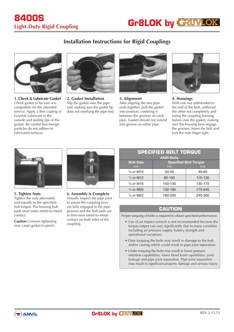
Installation Instructions for Rigid Couplings
1. Check & Lubricate GasketCheck gasket to be sure it is compatible for the intended service. Apply a thin coating of Gruvlok Lubricant to the outside and sealing lips of the gasket. Be careful that foreign particles do not adhere to lubricated surfaces.
2. Gasket InstallationSlip the gasket over the pipe end, making sure the gasket lip does not overhang the pipe end.
3. AlignmentAfter aligning the two pipe ends together, pull the gasket into position, centering it between the grooves on each pipe. Gasket should not extend into groove on either pipe.
4. HousingsWith one nut unthreaded to the end of the bolt, unthread the other nut completely and swing the coupling housing halves over the gasket, making sure the housing keys engage the grooves. Insert the bolt and turn the nuts finger tight.
5. Tighten NutsTighten the nuts alternately and equally to the specified bolt torque. The housing bolt pads must make metal-to-metal contact.
Caution: Uneven tightening may cause gasket to pinch.
6. Assembly is CompleteVisually inspect the pipe joint to assure the coupling keys are fully engaged in the pipe grooves and the bolt pads are in firm even metal-to-metal contact on both sides of the coupling.
CAUTION
Proper torquing of bolts is required to obtain specified performance.
torque output can vary significantly due to many variables including air pressure supply, battery strength and operational variations.
and/or casting which could result in pipe joint separation.
retention capabilities, lower bend load capabilities, joint leakage and pipe joint separation. Pipe joint separation may result in significant property damage and serious injury.
SPECIFIED BOLT TORQUEANSI Bolts
Bolt Size Specified Bolt TorqueInch ft-lb N-M
3⁄8 or M10 30-45 40-60
1⁄2 or M12 80-100 110-135
5⁄8 or M16 100-130 135-175
3⁄4 or M20 130-180 175-245
7⁄8 or M22 180-220 245-300

8400SLight-Duty Rigid Coupling Gr8LOK by
REV. 2.15.13Gr8LOK by
The 8400S Coupling is specially designed to provide a rigid, locked-in pipe connection to meet the specific demands of rigid design steel pipe systems. Fast and easy swing-over installation of the rugged lightweight housing produces a secure, rigid pipe joint.
For the latest UL/ULC listed, LPCB, VdS and FM Approvedpressure ratings versus pipe schedule, contact your local Anvil Representative.
MATERIAL SPECIFICATIONS
HOUSING:Ductile Iron conforming to ASTM A-536, Grade 65-45-12
ANSI BOLTS & HEAVY HEX NUTS:Heat treated, oval-neck track head bolts conforming to SAE J429 Grade 5 with a minimum tensile strength of 120,000 psi and heavy hex nuts of carbon steel conforming to ASTM A-563 Grade A or B, or SAE J995 Grade 2. Bolts and nuts are provided zinc electroplated as standard.
METRIC BOLTS & HEAVY HEX NUTS:Heat treated, zinc electroplated oval-neck track head bolts made of carbon steel with mechanical properties per ISO 898-1 Class 8.8. Hex nuts and bolts are zinc electroplated followed by a yellow chromate dip.
COATINGS:Rust inhibiting paint – Color: Red (standard)Hot Dipped Zinc Galvanized (optional)For other coating requirements contact an Anvil Representative.
GASKETS
Properties as designated in accordance with ASTM D-2000
GRADE ”E” EPDM (Green Stripe)Working Temperature Range is -30°F to 230°F (-34°C to 110°C)Recommended for water service, diluted acids, alkalies solu-tions, oil-free air and many chemical services.
NOT FOR USE IN PETROLEUM APPLICATIONS OR WITH HYDROCARBONS.

8400SLight-Duty Rigid Coupling Gr8LOK by
REV. 2.15.13Gr8LOK by
Nominal Sizemm/in
Pipe O.D.mm/in
WorkingPressure
MPa/PSI
Dimensions Bolt Size
Amm/in
Bmm/in
Cmm/in
No.-Sizemm
65 76.1 2.07 100 140 452 - M10 x 57
21/2 3.000 300 3.94 5.51 1.77
80 88.9 2.07 114 160 452 - M10 x 57
3 3.500 300 4.49 6.30 1.77
100 108.0 2.07 135 185 502 - M12 x 70
4 4.250 300 5.31 7.28 1.97
100 114.3 2.07 140 192 502 - M12 x 70
4 4.500 300 5.51 7.56 1.97
125 139.7 2.07 168 225 502 - M12 x 76
5 5.500 300 6.61 8.86 1.97
125 141.3 2.07 170 225 502 - M12 x 76
5 5.563 300 6.69 8.86 1.97
150 159.0 2.07 190 250 502 - M16 x 85
6 6.250 300 7.48 9.84 1.97
150 165.1 2.07 195 250 502 - M12 x 76
6 6.500 300 7.68 9.84 1.97
150 168.3 2.07 200 255 502 - M12 x 76
6 6.625 300 7.87 10.04 1.97
200 219.1 2.07 255 323 582 - M16 x 85
8 8.625 300 10.04 12.72 2.28
250 273.0 2.07 318 410 632 - M20 x 115
10 10.750 300 12.52 16.14 2.48
1. Working pressure and/or end load are total allowable, based on standard weight steel pipe, roll or cut grooved.
2. One time field test pressure may be increased to 1.5 times the figures listed above.
Working Pressure Ratings are for reference only and based on Sch. 40 pipe. For the latest UL/ULC, FM, VdS and LPCB pressure ratings versus
pipe schedule, please contact your local Anvil Representative.
8400SLight-Duty Rigid Coupling Gr8LOK by
REV. 2.15.13Gr8LOK by
Installation Instructions for Rigid Couplings
1. Check & Lubricate GasketCheck gasket to be sure it is compatible for the intended service. Apply a thin coating of Gruvlok Lubricant to the outside and sealing lips of the gasket. Be careful that foreign particles do not adhere to lubricated surfaces.
2. Gasket InstallationSlip the gasket over the pipe end, making sure the gasket lip does not overhang the pipe end.
3. AlignmentAfter aligning the two pipe ends together, pull the gasket into position, centering it between the grooves on each pipe. Gasket should not extend into groove on either pipe.
4. HousingsWith one nut unthreaded to the end of the bolt, unthread the other nut completely and swing the coupling housing halves over the gasket, making sure the housing keys engage the grooves. Insert the bolt and turn the nuts finger tight.
5. Tighten NutsTighten the nuts alternately and equally to the specified bolt torque. The housing bolt pads must make metal-to-metal contact.
Caution: Uneven tightening may cause gasket to pinch.
6. Assembly is CompleteVisually inspect the pipe joint to assure the coupling keys are fully engaged in the pipe grooves and the bolt pads are in firm even metal-to-metal contact on both sides of the coupling.
CAUTION
Proper torquing of bolts is required to obtain specified performance.
torque output can vary significantly due to many variables including air pressure supply, battery strength and operational variations.
and/or casting which could result in pipe joint separation.
retention capabilities, lower bend load capabilities, joint leakage and pipe joint separation. Pipe joint separation may result in significant property damage and serious injury.
SPECIFIED BOLT TORQUEANSI Bolts
Bolt Size Specified Bolt TorqueInch ft-lb N-M
3⁄8 or M10 30-45 40-60
1⁄2 or M12 80-100 110-135
5⁄8 or M16 100-130 135-175
3⁄4 or M20 130-180 175-245
7⁄8 or M22 180-220 245-300

8000Flexible Coupling Gr8LOK by
REV. 2.6.13Gr8LOK by
The 8000 Coupling is a flexible light weight style which isideal for fire protection services and other services where low pressure and ambient temperature conditions are expected.
For the latest UL/ULC listed, LPCB, VdS and FM Approvedpressure ratings versus pipe schedule, contact your local Anvil Representative.
MATERIAL SPECIFICATIONS
HOUSING:Ductile Iron conforming to ASTM A-536, Grade 65-45-12
ANSI BOLTS & HEAVY HEX NUTS:Heat treated, oval-neck track head bolts conforming to SAE J429 Grade 5 with a minimum tensile strength of 120,000 psi and heavy hex nuts of carbon steel conforming to ASTM A-563 Grade A or B, or SAE J995 Grade 2. Bolts and nuts are provided zinc electroplated as standard.
METRIC BOLTS & HEAVY HEX NUTS:Heat treated, zinc electroplated oval-neck track head bolts made of carbon steel with mechanical properties per ISO 898-1 Class 8.8. Hex nuts and bolts are zinc electroplated followed by a yellow chromate dip.
COATINGS:Rust inhibiting paint – Color: Red (standard)Hot Dipped Zinc Galvanized (optional)For other coating requirements contact an Anvil Representative.
GASKETS
Properties as designated in accordance with ASTM D-2000
GRADE ”E” EPDM (Green Stripe)Working Temperature Range is -30°F to 230°F (-34°C to 110°C)Recommended for water service, diluted acids, alkalies solu-tions, oil-free air and many chemical services.
NOT FOR USE IN PETROLEUM APPLICATIONS OR WITH HYDROCARBONS.
GASKET TYPE:Standard C StyleEPDM F

8000Flexible Coupling Gr8LOK by
REV. 2.6.13Gr8LOK by
Nominal Sizemm/in
Pipe O.D.mm/in
WorkingPressure
MPa/PSI
Dimensions Bolt Size Approx.Wt. Ea.
Kg/lbs
Amm/in
Bmm/in
Cmm/in
No.-Sizemm
25 33.7 3.45 55 92 422 - M10 x 57
0.401 1.327 500 2.17 3.62 1.65 0.88
32 42.4 3.45 65 104 442 - M10 x 57
0.4511/4 1.669 500 2.56 4.14 1.74 1.00
40 48.3 3.45 70 110 442 - M10 x 57
0.5611/2 1.900 500 2.75 4.33 1.74 1.24
50 60.3 3.45 83 124 442 - M10 x 57
0.602 2.375 500 3.27 4.88 1.74 1.33
65 73.0 3.45 96 143 452 - M10 x 57
0.6521/2 2.875 500 3.78 5.63 1.78 1.44
65 76.1 3.45 100 145 452 - M10 x 57
0.8421/2 3.000 500 3.94 5.71 1.78 1.85
80 88.9 3.45 115 160 452 - M12 x 70
0.863 3.500 500 4.53 6.30 1.78 1.89
100 108.0 3.45 138 190 502 - M12 x 70
1.214 4.250 500 5.43 7.48 1.97 2.66
100 114.3 3.45 145 198 502 - M12 x 70
1.694 4.500 500 5.71 7.80 1.97 3.73
125 133 3.10 162 225 512 - M16 x 85
1.755 5.250 450 6.38 8.86 2.01 3.87
125 139.7 3.10 169 230 522 - M16 x 85
2.375 5.500 450 6.65 9.06 2.05 5.22
125 141.3 3.10 170 232 512 - M16 x 85
2.525 5.563 450 6.69 9.13 2.01 5.56
150 159.0 3.10 190 254 522 - M16 x 85
2.276 6.250 450 7.48 10.00 2.05 5.01
150 165.1 3.10 196 260 522 - M16 x 85
2.646 6.500 450 7.72 10.24 2.05 5.82
150 168.3 3.10 200 265 522 - M16 x 85
2.656 6.625 450 7.87 10.43 2.05 5.85
200 219.1 3.10 262 340 602 - M20 x 115
3.098 8.625 450 10.31 13.39 2.37 6.81
250 273.0 2.07 327 420 63.52 - M22 x 140
5.4410 10.750 300 12.87 16.54 2.50 11.98
300 323.9 2.07 378 462.5 652 - M22 x 140
10.7912 12.750 300 14.88 18.21 2.56 23.78
1. Working pressure and/or end load are total allowable, based on standard weight steel pipe, roll or cut grooved.
2. One time field test pressure may be increased to 1.5 times the figures listed above.
Working Pressure Ratings are for reference only and based on Sch. 40 pipe. For the latest UL/ULC, FM, VdS and LPCB pressure ratings versus
pipe schedule, please contact your local Anvil Representative.

8000Flexible Coupling Gr8LOK by
REV. 2.6.13Gr8LOK by
Installation Instructions for Flexible Couplings
1. Check & Lubricate GasketCheck gasket to be sure it is compatible for the intended service. Apply a thin coating of Gruvlok lubricant to the ex-terior surface and sealing lips of the gasket. Be careful that foreign particles do not adhere to lubricated surfaces.
2. Gasket InstallationSlip the gasket over the pipe end, making sure the gasket lip does not overhang the pipe end.
3. AlignmentAfter aligning the two pipe ends together, pull the gasket into position, centering it between the grooves on each pipe. Gasket should not extend into groove on either pipe.
4. HousingsWith one nut unthreaded to the end of the bolt, unthread the other nut completely and swing the coupling housing halves over the gasket, making sure the housing keys engage the grooves. Insert the bolt and turn the nuts finger tight.
5. Tighten NutsTighten the nuts alternately and equally to the specified bolt torque. The housing bolt pads must make metal-to-metal contact.
Caution: Uneven tightening may cause gasket to pinch.
6. Assembly is CompleteVisually inspect the pipe joint to assure the coupling keys are fully engaged in the pipe grooves and the bolt pads are in firm even metal-to-metal contact on both sides of the coupling.
CAUTION
Proper torquing of bolts is required to obtain specified performance.
torque output can vary significantly due to many variables including air pressure supply, battery strength and operational variations.
and/or casting which could result in pipe joint separation.
retention capabilities, lower bend load capabilities, joint leakage and pipe joint separation. Pipe joint separation may result in significant property damage and serious injury.
SPECIFIED BOLT TORQUEANSI Bolts
Bolt Size Specified Bolt TorqueInch ft-lb N-M
3⁄8 or M10 30-45 40-60
1⁄2 or M12 80-100 110-135
5⁄8 or M16 100-130 135-175
3⁄4 or M20 130-180 175-245
7⁄8 or M22 180-220 245-300

8450Short Style 90˚ Elbow Gr8LOK by
REV. 5.7.14Gr8LOK by
MATERIAL SPECIFICATIONS
CAST FITTINGS:Ductile Iron conforming to ASTM A-536
FINISH:Rust inhibiting paint – Color: Red (standard)Hot Dipped Zinc Galvanized conforming to ASTM A-153 (optional)For other coating requirements contact an Anvil Representative.
NominalSizemm/in
Pipe O.D.mm/in
Max.WorkingPressure
MPa/PSI
DimensionsL
mm/in
50 60.3 2.07 70.02 2.375 300 2.76
65 73.0 2.07 76.021/2 2.875 300 2.9965 76.1 2.07 76.021/2 3.000 300 2.9980 88.9 2.07 85.53 3.500 300 3.37
100 108.0 2.07 101.04 4.250 300 3.98
100 114.3 2.07 101.04 4.500 300 3.98
125 139.7 2.07 124.05 5.500 300 4.88
150 159.0 2.07 140.06 6.250 300 5.51
150 165.1 2.07 140.06 6.500 300 5.51
150 168.3 2.07 140.06 6.625 300 5.51
200 216.3 2.07 175.08 8.516 300 6.89
200 219.1 2.07 165.08 8.625 300 6.50

805090˚ Elbow
Gr8LOK by
REV. 2.6.13Gr8LOK by
MATERIAL SPECIFICATIONS
CAST FITTINGS:
Ductile Iron conforming to ASTM A-536
FINISH:
Rust inhibiting paint – Color: Red (standard)Hot Dipped Zinc Galvanized conforming to ASTM A-153 (optional)For other coating requirements contact an Anvil Representative.
NominalSizemm/in
Pipe O.D.mm/in
Max.WorkingPressure
MPa/PSI
Centerto End
mm/in
Approx.Weight Ea.
Kg/lbs
25 33.7 3.45 57 0.241 1.327 500 2.24 0.52
32 42.4 3.45 70 0.4111/4 1.669 500 2.75 0.91
40 48.3 3.45 70 0.4811/2 1.900 500 2.75 1.06
50 60.3 3.45 82.5 0.652 2.375 500 3.25 1.44
65 73.0 3.45 95 1.1021/2 2.875 500 3.74 2.42
65 76.1 3.45 95 1.1521/2 3.000 500 3.74 2.54
80 88.9 3.45 108 1.613 3.500 500 4.25 3.54
100 114.3 3.45 127 2.664 4.500 500 5.00 5.87
125 139.7 3.45 140 4.095 5.500 500 5.50 9.02
125 141.3 3.45 140 4.235 5.563 500 5.50 9.33
150 165.1 3.45 165 5.996 6.500 500 6.50 13.21
150 168.3 3.45 165 6.076 6.625 500 6.50 13.38
200 219.1 3.45 197 11.128 8.625 500 7.75 24.51
250 273.0 3.45 229 24.5810 10.750 500 9.00 54.19
300 323.9 3.45 254 35.5212 12.750 500 10.00 78.31

805145˚ Elbow
Gr8LOK by
REV. 2.7.13Gr8LOK by
MATERIAL SPECIFICATIONS
CAST FITTINGS:
Ductile Iron conforming to ASTM A-536
FINISH:
Rust inhibiting paint – Color: Red (standard)Hot Dipped Zinc Galvanized conforming to ASTM A-153 (optional)For other coating requirements contact an Anvil Representative.
NominalSizemm/in
Pipe O.D.mm/in
Max.WorkingPressure
MPa/PSI
DimensionsL
mm/in
25 33.7 3.45 44.5
1 1.327 500 1.75
32 42.4 3.45 44.5
11/4 1.669 500 1.75
40 48.3 3.45 44.5
11/2 1.900 500 1.75
50 60.3 3.45 51.0
2 2.375 500 2.00
65 73.0 3.45 57.0
21/2 2.875 500 2.24
65 76.1 3.45 57.0
21/2 3.000 500 2.24
80 88.9 3.45 63.5
3 3.500 500 2.50
100 108.0 3.45 76.0
4 4.250 500 3.00
100 114.3 3.45 76.0
4 4.500 500 3.00
125 133.0 3.45 82.5
5 5.250 500 3.25
125 139.7 3.45 82.5
5 5.500 500 3.25
125 141.3 3.45 82.5
5 5.563 500 3.25
150 159.0 3.45 89.0
6 6.250 500 3.50
150 165.1 3.45 89.0
6 6.500 500 3.50
150 168.3 3.45 89.0
6 6.625 500 3.50
200 216.3 3.45 108.0
8 8.516 500 4.25
200 219.1 3.45 108.0
8 8.625 500 4.25
250 267.4 3.45 120.5
10 10.528 500 4.75
250 273.0 3.45 120.5
10 10.750 500 4.75
300 318.5 3.45 133.0
12 12.750 500 5.25
300 323.9 3.45 133.0
12 12.750 500 5.25
350 377.0 2.07 122.0
14 14.840 300 4.80

8052221/2˚ Elbow
Gr8LOK by
REV. 2.6.13Gr8LOK by
MATERIAL SPECIFICATIONS
CAST FITTINGS:
Ductile Iron conforming to ASTM A-536
FINISH:
Rust inhibiting paint – Color: Red (standard)Hot Dipped Zinc Galvanized conforming to ASTM A-153 (optional)For other coating requirements contact an Anvil Representative.
NominalSizemm/in
Pipe O.D.mm/in
Max.WorkingPressure
MPa/PSI
DimensionsL
mm/in
32 42.4 3.45 45
11/4 1.669 500 1.77
40 48.3 3.45 45
11/2 1.900 500 1.77
50 60.3 3.45 48
2 2.375 500 1.89
65 73.0 3.45 51
21/2 2.875 500 2.00
65 76.1 3.45 51
21/2 3.000 500 2.00
80 88.9 3.45 57
3 3.500 500 2.24
100 108.0 3.45 73
4 4.250 500 2.87
100 114.3 3.45 73
4 4.500 500 2.87
125 139.7 3.45 73
5 5.500 500 2.87
150 159.0 3.45 79
6 6.250 500 3.11
150 165.1 3.45 79
6 6.500 500 3.11
150 168.3 3.45 79
6 6.625 500 3.11
200 219.1 3.45 98
8 8.625 500 3.86

8053111/4˚ Elbow
Gr8LOK by
REV. 2.12.13Gr8LOK by
MATERIAL SPECIFICATIONS
CAST FITTINGS:
Ductile Iron conforming to ASTM A-536
FINISH:
Rust inhibiting paint – Color: Red (standard)Hot Dipped Zinc Galvanized conforming to ASTM A-153 (optional)For other coating requirements contact an Anvil Representative.
NominalSizemm/in
Pipe O.D.mm/in
Max.WorkingPressure
MPa/PSI
DimensionsL
mm/in
32 42.4 3.45 35
11/4 1.669 500 1.38
40 48.3 3.45 35
11/2 1.900 500 1.38
50 60.3 3.45 35
2 2.375 500 1.38
65 76.1 3.45 38
21/2 3.000 500 1.50
80 88.9 3.45 38
3 3.500 500 1.50
100 108.0 3.45 44
4 4.250 500 1.73
100 114.3 3.45 44
4 4.500 500 1.73
125 139.7 3.45 51
5 5.500 500 2.00
150 159.0 3.45 51
6 6.250 500 2.00
150 165.1 3.45 51
6 6.500 500 2.00
150 168.3 3.45 51
6 6.625 500 2.00
200 219.1 3.45 51
8 8.625 500 2.00

8460Short Style Tee Gr8LOK by
REV. 5.7.14Gr8LOK by
MATERIAL SPECIFICATIONS
CAST FITTINGS:Ductile Iron conforming to ASTM A-536
FINISH:Rust inhibiting paint – Color: Red (standard)Hot Dipped Zinc Galvanized conforming to ASTM A-153 (optional)For other coating requirements contact an Anvil Representative.
NominalSizemm/in
Pipe O.D.mm/in
Max.WorkingPressure
MPa/PSI
DimensionsL
mm/in
50 60.3 2.07 70.02 2.375 300 2.75
65 73.0 2.07 76.021/2 2.875 300 3.0065 76.1 2.07 76.021/2 3.000 300 3.0080 88.9 2.07 85.53 3.500 300 3.37
100 108.0 2.07 101.04 4.250 300 3.98
100 114.3 2.07 101.04 4.500 300 3.98
125 139.7 2.07 124.05 5.500 300 4.88
150 159.0 2.07 140.06 6.250 300 5.50
150 165.1 2.07 140.06 6.500 300 5.50
150 168.3 2.07 140.06 6.625 300 5.50
200 216.3 2.07 175.08 8.516 300 6.89
200 219.1 2.07 175.08 8.625 300 6.89

8060Tee
Gr8LOK by
REV. 2.6.13Gr8LOK by
MATERIAL SPECIFICATIONS
CAST FITTINGS:
Ductile Iron conforming to ASTM A-536
FINISH:
Rust inhibiting paint – Color: Red (standard)Hot Dipped Zinc Galvanized conforming to ASTM A-153 (optional)For other coating requirements contact an Anvil Representative.
NominalSizemm/in
Pipe O.D.mm/in
Max.WorkingPressure
MPa/PSI
DimensionsL
mm/in
25 33.7 3.45 57.0
1 1.327 500 2.24
32 42.4 3.45 70.0
11/4 1.669 500 2.75
40 48.3 3.45 70.0
11/2 1.900 500 2.75
50 60.3 3.45 82.5
2 2.375 500 3.25
65 73.0 3.45 95.0
21/2 2.875 500 3.74
65 76.1 3.45 95.0
21/2 3.000 500 3.74
80 88.9 3.45 108.0
3 3.500 500 4.25
100 114.3 3.45 127.0
4 4.500 500 5.00
125 133.0 3.45 122.0
5 5.250 500 4.80
125 139.7 3.45 140.0
5 5.500 500 5.50
125 141.3 3.45 140.0
5 5.563 500 5.50
150 165.1 3.45 165.0
6 6.500 500 6.50
150 168.3 3.45 165.0
6 6.625 500 6.50
200 219.1 3.45 197.0
8 8.625 500 7.75
250 267.4 3.45 229.0
10 10.528 500 9.00
250 273.0 3.45 229.0
10 10.750 500 9.00
300 318.5 3.45 254.0
12 12.539 500 10.00
300 323.9 3.45 254.0
12 12.750 500 10.00
350 377.0 2.07 279.0
14 14.840 300 10.98
400 426.0 2.07 305.0
16 16.770 300 12.00
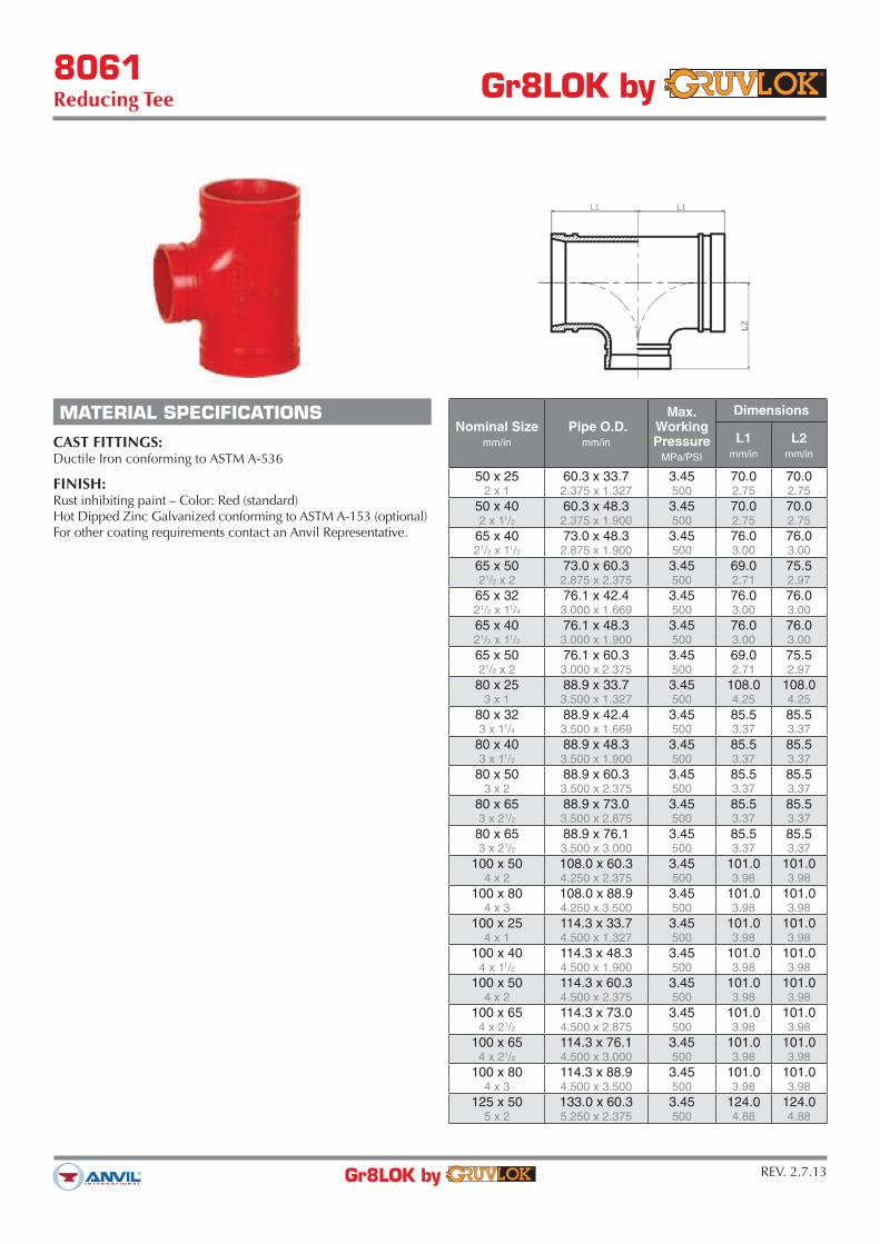
8061Reducing Tee Gr8LOK by
REV. 2.7.13Gr8LOK by
MATERIAL SPECIFICATIONS
CAST FITTINGS:Ductile Iron conforming to ASTM A-536
FINISH:Rust inhibiting paint – Color: Red (standard)Hot Dipped Zinc Galvanized conforming to ASTM A-153 (optional)For other coating requirements contact an Anvil Representative.
Nominal Sizemm/in
Pipe O.D.mm/in
Max.WorkingPressure
MPa/PSI
Dimensions
L1mm/in
L2mm/in
50 x 25 60.3 x 33.7 3.45 70.0 70.0
2 x 1 2.375 x 1.327 500 2.75 2.75
50 x 40 60.3 x 48.3 3.45 70.0 70.0
2 x 11/2 2.375 x 1.900 500 2.75 2.75
65 x 40 73.0 x 48.3 3.45 76.0 76.0
21/2 x 11/2 2.875 x 1.900 500 3.00 3.00
65 x 50 73.0 x 60.3 3.45 69.0 75.5
21/2 x 2 2.875 x 2.375 500 2.71 2.97
65 x 32 76.1 x 42.4 3.45 76.0 76.0
21/2 x 11/4 3.000 x 1.669 500 3.00 3.00
65 x 40 76.1 x 48.3 3.45 76.0 76.0
21/2 x 11/2 3.000 x 1.900 500 3.00 3.00
65 x 50 76.1 x 60.3 3.45 69.0 75.5
21/2 x 2 3.000 x 2.375 500 2.71 2.97
80 x 25 88.9 x 33.7 3.45 108.0 108.0
3 x 1 3.500 x 1.327 500 4.25 4.25
80 x 32 88.9 x 42.4 3.45 85.5 85.5
3 x 11/4 3.500 x 1.669 500 3.37 3.37
80 x 40 88.9 x 48.3 3.45 85.5 85.5
3 x 11/2 3.500 x 1.900 500 3.37 3.37
80 x 50 88.9 x 60.3 3.45 85.5 85.5
3 x 2 3.500 x 2.375 500 3.37 3.37
80 x 65 88.9 x 73.0 3.45 85.5 85.5
3 x 21/2 3.500 x 2.875 500 3.37 3.37
80 x 65 88.9 x 76.1 3.45 85.5 85.5
3 x 21/2 3.500 x 3.000 500 3.37 3.37
100 x 50 108.0 x 60.3 3.45 101.0 101.0
4 x 2 4.250 x 2.375 500 3.98 3.98
100 x 80 108.0 x 88.9 3.45 101.0 101.0
4 x 3 4.250 x 3.500 500 3.98 3.98
100 x 25 114.3 x 33.7 3.45 101.0 101.0
4 x 1 4.500 x 1.327 500 3.98 3.98
100 x 40 114.3 x 48.3 3.45 101.0 101.0
4 x 11/2 4.500 x 1.900 500 3.98 3.98
100 x 50 114.3 x 60.3 3.45 101.0 101.0
4 x 2 4.500 x 2.375 500 3.98 3.98
100 x 65 114.3 x 73.0 3.45 101.0 101.0
4 x 21/2 4.500 x 2.875 500 3.98 3.98
100 x 65 114.3 x 76.1 3.45 101.0 101.0
4 x 21/2 4.500 x 3.000 500 3.98 3.98
100 x 80 114.3 x 88.9 3.45 101.0 101.0
4 x 3 4.500 x 3.500 500 3.98 3.98
125 x 50 133.0 x 60.3 3.45 124.0 124.0
5 x 2 5.250 x 2.375 500 4.88 4.88
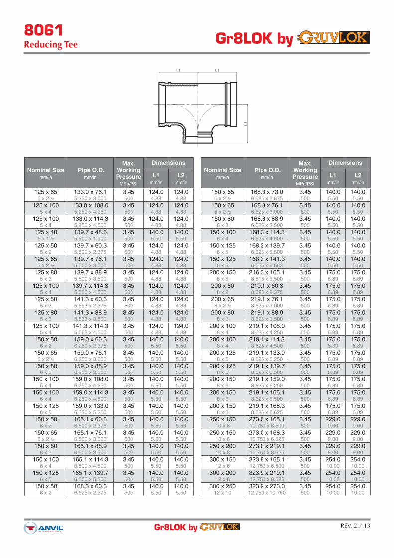
8061Reducing Tee Gr8LOK by
REV. 2.7.13Gr8LOK by
Nominal Sizemm/in
Pipe O.D.mm/in
Max.WorkingPressure
MPa/PSI
Dimensions
L1mm/in
L2mm/in
125 x 65 133.0 x 76.1 3.45 124.0 124.0
5 x 21/2 5.250 x 3.000 500 4.88 4.88
125 x 100 133.0 x 108.0 3.45 124.0 124.0
5 x 4 5.250 x 4.250 500 4.88 4.88
125 x 100 133.0 x 114.3 3.45 124.0 124.0
5 x 4 5.250 x 4.500 500 4.88 4.88
125 x 40 139.7 x 48.3 3.45 140.0 140.0
5 x 11/2 5.500 x 1.900 500 5.50 5.50
125 x 50 139.7 x 60.3 3.45 124.0 124.0
5 x 2 5.500 x 2.375 500 4.88 4.88
125 x 65 139.7 x 76.1 3.45 124.0 124.0
5 x 21/2 5.500 x 3.000 500 4.88 4.88
125 x 80 139.7 x 88.9 3.45 124.0 124.0
5 x 3 5.500 x 3.500 500 4.88 4.88
125 x 100 139.7 x 114.3 3.45 124.0 124.0
5 x 4 5.500 x 4.500 500 4.88 4.88
125 x 50 141.3 x 60.3 3.45 124.0 124.0
5 x 2 5.563 x 2.375 500 4.88 4.88
125 x 80 141.3 x 88.9 3.45 124.0 124.0
5 x 3 5.563 x 3.500 500 4.88 4.88
125 x 100 141.3 x 114.3 3.45 124.0 124.0
5 x 4 5.563 x 4.500 500 4.88 4.88
150 x 50 159.0 x 60.3 3.45 140.0 140.0
6 x 2 6.250 x 2.375 500 5.50 5.50
150 x 65 159.0 x 76.1 3.45 140.0 140.0
6 x 21/2 6.250 x 3.000 500 5.50 5.50
150 x 80 159.0 x 88.9 3.45 140.0 140.0
6 x 3 6.250 x 3.500 500 5.50 5.50
150 x 100 159.0 x 108.0 3.45 140.0 140.0
6 x 4 6.250 x 4.250 500 5.50 5.50
150 x 100 159.0 x 114.3 3.45 140.0 140.0
6 x 4 6.250 x 4.500 500 5.50 5.50
150 x 125 159.0 x 133.0 3.45 140.0 140.0
6 x 5 6.250 x 5.250 500 5.50 5.50
150 x 50 165.1 x 60.3 3.45 140.0 140.0
6 x 2 6.500 x 2.375 500 5.50 5.50
150 x 65 165.1 x 76.1 3.45 140.0 140.0
6 x 21/2 6.500 x 3.000 500 5.50 5.50
150 x 80 165.1 x 88.9 3.45 140.0 140.0
6 x 3 6.500 x 3.500 500 5.50 5.50
150 x 100 165.1 x 114.3 3.45 140.0 140.0
6 x 4 6.500 x 4.500 500 5.50 5.50
150 x 125 165.1 x 139.7 3.45 140.0 140.0
6 x 5 6.500 x 5.500 500 5.50 5.50
150 x 50 168.3 x 60.3 3.45 140.0 140.0
6 x 2 6.625 x 2.375 500 5.50 5.50
Nominal Sizemm/in
Pipe O.D.mm/in
Max.WorkingPressure
MPa/PSI
Dimensions
L1mm/in
L2mm/in
150 x 65 168.3 x 73.0 3.45 140.0 140.0
6 x 21/2 6.625 x 2.875 500 5.50 5.50
150 x 65 168.3 x 76.1 3.45 140.0 140.0
6 x 21/2 6.625 x 3.000 500 5.50 5.50
150 x 80 168.3 x 88.9 3.45 140.0 140.0
6 x 3 6.625 x 3.500 500 5.50 5.50
150 x 100 168.3 x 114.3 3.45 140.0 140.0
6 x 4 6.625 x 4.500 500 5.50 5.50
150 x 125 168.3 x 139.7 3.45 140.0 140.0
6 x 5 6.625 x 5.500 500 5.50 5.50
150 x 125 168.3 x 141.3 3.45 140.0 140.0
6 x 5 6.625 x 5.563 500 5.50 5.50
200 x 150 216.3 x 165.1 3.45 175.0 175.0
8 x 6 8.516 x 6.500 500 6.89 6.89
200 x 50 219.1 x 60.3 3.45 175.0 175.0
8 x 2 8.625 x 2.375 500 6.89 6.89
200 x 65 219.1 x 76.1 3.45 175.0 175.0
8 x 21/2 8.625 x 3.000 500 6.89 6.89
200 x 80 219.1 x 88.9 3.45 175.0 175.0
8 x 3 8.625 x 3.500 500 6.89 6.89
200 x 100 219.1 x 108.0 3.45 175.0 175.0
8 x 4 8.625 x 4.250 500 6.89 6.89
200 x 100 219.1 x 114.3 3.45 175.0 175.0
8 x 4 8.625 x 4.500 500 6.89 6.89
200 x 125 219.1 x 133.0 3.45 175.0 175.0
8 x 5 8.625 x 5.250 500 6.89 6.89
200 x 125 219.1 x 139.7 3.45 175.0 175.0
8 x 5 8.625 x 5.500 500 6.89 6.89
200 x 150 219.1 x 159.0 3.45 175.0 175.0
8 x 6 8.625 x 6.250 500 6.89 6.89
200 x 150 219.1 x 165.1 3.45 175.0 175.0
8 x 6 8.625 x 6.500 500 6.89 6.89
200 x 150 219.1 x 168.3 3.45 175.0 175.0
8 x 6 8.625 x 6.625 500 6.89 6.89
250 x 150 273.0 x 165.1 3.45 229.0 229.0
10 x 6 10.750 x 6.500 500 9.00 9.00
250 x 150 273.0 x 168.3 3.45 229.0 229.0
10 x 6 10.750 x 6.625 500 9.00 9.00
250 x 200 273.0 x 219.1 3.45 229.0 229.0
10 x 8 10.750 x 8.625 500 9.00 9.00
300 x 150 323.9 x 165.1 3.45 254.0 254.0
12 x 6 12.750 x 6.500 500 10.00 10.00
300 x 200 323.9 x 219.1 3.45 254.0 254.0
12 x 8 12.750 x 8.625 500 10.00 10.00
300 x 250 323.9 x 273.0 3.45 254.0 254.0
12 x 10 12.750 x 10.750 500 10.00 10.00

8068Cross
Gr8LOK by
REV. 2.6.13Gr8LOK by
MATERIAL SPECIFICATIONS
CAST FITTINGS:
Ductile Iron conforming to ASTM A-536
FINISH:
Rust inhibiting paint – Color: Red (standard)Hot Dipped Zinc Galvanized conforming to ASTM A-153 (optional)For other coating requirements contact an Anvil Representative.
NominalSizemm/in
Pipe O.D.mm/in
Max.WorkingPressure
MPa/PSI
DimensionsL
mm/in
32 42.4 3.45 70.0
11/4 1.669 500 2.75
40 48.3 3.45 70.0
11/2 1.900 500 2.75
50 60.3 3.45 70.0
2 2.375 500 2.75
65 73.0 3.45 76.0
21/2 2.875 500 3.00
65 76.1 3.45 76.0
21/2 3.000 500 3.00
80 88.9 3.45 85.5
3 3.500 500 3.37
100 108.0 3.45 101.0
4 4.250 500 3.98
100 114.3 3.45 101.0
4 4.500 500 3.98
125 139.7 3.45 124.0
5 5.500 500 4.88
125 141.3 3.45 124.0
5 5.563 500 4.88
150 159.0 3.45 140.0
6 6.250 500 5.50
150 165.1 3.45 140.0
6 6.500 500 5.50
150 168.3 3.45 140.0
6 6.625 500 5.50
200 219.1 3.45 175.0
8 8.625 500 6.89
250 273.0 3.45 229.0
10 10.750 500 9.00
300 323.9 3.45 254.0
12 12.750 500 10.00

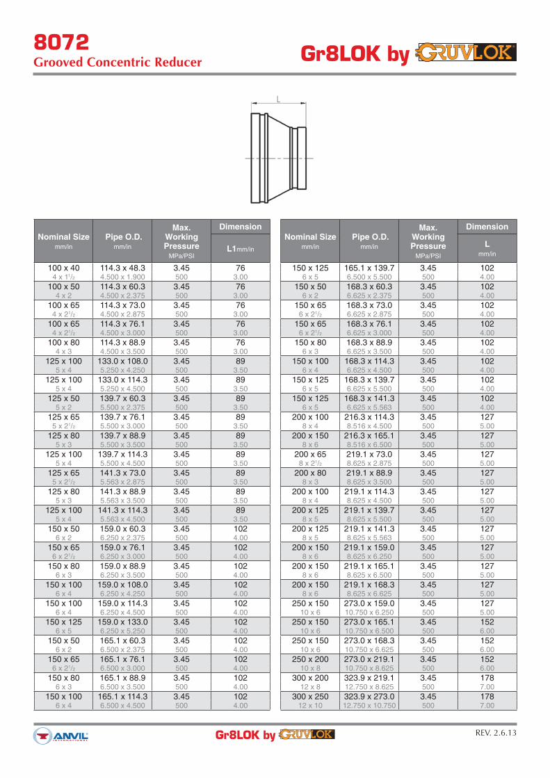
8072Grooved Concentric Reducer
Gr8LOK by
REV. 2.6.13Gr8LOK by
MATERIAL SPECIFICATIONS
CAST FITTINGS:
Ductile Iron conforming to ASTM A-536
FINISH:
Rust inhibiting paint – Color: Red (standard)Hot Dipped Zinc Galvanized conforming to ASTM A-153 (optional)For other coating requirements contact an Anvil Representative.
Nominal Sizemm/in
Pipe O.D.mm/in
Max.WorkingPressure
MPa/PSI
Dimension
Lmm/in
32 x 25 42.4 x 33.7 3.45 64
11/4 x 1 1.669 x 1.327 500 2.50
40 x 25 48.3 x 33.7 3.45 64
11/2 x 1 1.900 x 1.327 500 2.50
40 x 32 48.3 x 42.4 3.45 64
11/2 x 11/4 1.900 x 1.669 500 2.50
50 x 25 60.3 x 33.7 3.45 64
2 x 1 2.375 x 1.327 500 2.50
50 x 32 60.3 x 42.4 3.45 64
2 x 11/4 2.375 x 1.669 500 2.50
50 x 40 60.3 x 48.3 3.45 64
2 x 11/2 2.375 x 1.900 500 2.50
65 x 32 73.0 x 42.4 3.45 64
21/2 x 11/4 2.875 x 1.669 500 2.50
65 x 40 73.0 x 48.3 3.45 64
21/2 x 11/2 2.875 x 1.900 500 2.50
65 x 50 73.0 x 60.3 3.45 64
21/2 x 2 2.875 x 2.375 500 2.50
65 x 25 76.1 x 33.7 3.45 64
21/2 x 1 3.000 x 1.327 500 2.50
65 x 32 76.1 x 42.4 3.45 64
21/2 x 11/4 3.000 x 1.669 500 2.50
65 x 40 76.1 x 48.3 3.45 64
21/2 x 11/2 3.000 x 1.900 500 2.50
65 x 50 76.1 x 60.3 3.45 64
21/2 x 2 3.000 x 2.375 500 2.50
80 x 25 88.9 x 33.7 3.45 64
3 x 1 3.500 x 1.327 500 2.50
80 x 40 88.9 x 48.3 3.45 64
3 x 11/2 3.500 x 1.900 500 2.50
80 x 50 88.9 x 60.3 3.45 64
3 x 2 3.500 x 2.375 500 2.50
80 x 65 88.9 x 73.0 3.45 64
3 x 21/2 3.500 x 2.875 500 2.50
80 x 65 88.9 x 76.1 3.45 64
3 x 21/2 3.500 x 3.000 500 2.50
100 x 50 108.0 x 60.3 3.45 76
4 x 2 4.250 x 2.375 500 3.00
100 x 65 108.0 x 73.0 3.45 76
4 x 21/2 4.250 x 2.875 500 3.00
100 x 80 108.0 x 88.9 3.45 76
4 x 3 4.250 x 3.500 500 3.00
100 x 32 114.3 x 42.4 3.45 76
4 x 11/4 4.500 x 1.660 500 3.00
8072Grooved Concentric Reducer
Gr8LOK by
REV. 2.6.13Gr8LOK by
Nominal Sizemm/in
Pipe O.D.mm/in
Max.WorkingPressure
MPa/PSI
Dimension
L1mm/in
100 x 40 114.3 x 48.3 3.45 76
4 x 11/2 4.500 x 1.900 500 3.00
100 x 50 114.3 x 60.3 3.45 76
4 x 2 4.500 x 2.375 500 3.00
100 x 65 114.3 x 73.0 3.45 76
4 x 21/2 4.500 x 2.875 500 3.00
100 x 65 114.3 x 76.1 3.45 76
4 x 21/2 4.500 x 3.000 500 3.00
100 x 80 114.3 x 88.9 3.45 76
4 x 3 4.500 x 3.500 500 3.00
125 x 100 133.0 x 108.0 3.45 89
5 x 4 5.250 x 4.250 500 3.50
125 x 100 133.0 x 114.3 3.45 89
5 x 4 5.250 x 4.500 500 3.50
125 x 50 139.7 x 60.3 3.45 89
5 x 2 5.500 x 2.375 500 3.50
125 x 65 139.7 x 76.1 3.45 89
5 x 21/2 5.500 x 3.000 500 3.50
125 x 80 139.7 x 88.9 3.45 89
5 x 3 5.500 x 3.500 500 3.50
125 x 100 139.7 x 114.3 3.45 89
5 x 4 5.500 x 4.500 500 3.50
125 x 65 141.3 x 73.0 3.45 89
5 x 21/2 5.563 x 2.875 500 3.50
125 x 80 141.3 x 88.9 3.45 89
5 x 3 5.563 x 3.500 500 3.50
125 x 100 141.3 x 114.3 3.45 89
5 x 4 5.563 x 4.500 500 3.50
150 x 50 159.0 x 60.3 3.45 102
6 x 2 6.250 x 2.375 500 4.00
150 x 65 159.0 x 76.1 3.45 102
6 x 21/2 6.250 x 3.000 500 4.00
150 x 80 159.0 x 88.9 3.45 102
6 x 3 6.250 x 3.500 500 4.00
150 x 100 159.0 x 108.0 3.45 102
6 x 4 6.250 x 4.250 500 4.00
150 x 100 159.0 x 114.3 3.45 102
6 x 4 6.250 x 4.500 500 4.00
150 x 125 159.0 x 133.0 3.45 102
6 x 5 6.250 x 5.250 500 4.00
150 x 50 165.1 x 60.3 3.45 102
6 x 2 6.500 x 2.375 500 4.00
150 x 65 165.1 x 76.1 3.45 102
6 x 21/2 6.500 x 3.000 500 4.00
150 x 80 165.1 x 88.9 3.45 102
6 x 3 6.500 x 3.500 500 4.00
150 x 100 165.1 x 114.3 3.45 102
6 x 4 6.500 x 4.500 500 4.00
Nominal Sizemm/in
Pipe O.D.mm/in
Max.WorkingPressure
MPa/PSI
Dimension
Lmm/in
150 x 125 165.1 x 139.7 3.45 102
6 x 5 6.500 x 5.500 500 4.00
150 x 50 168.3 x 60.3 3.45 102
6 x 2 6.625 x 2.375 500 4.00
150 x 65 168.3 x 73.0 3.45 102
6 x 21/2 6.625 x 2.875 500 4.00
150 x 65 168.3 x 76.1 3.45 102
6 x 21/2 6.625 x 3.000 500 4.00
150 x 80 168.3 x 88.9 3.45 102
6 x 3 6.625 x 3.500 500 4.00
150 x 100 168.3 x 114.3 3.45 102
6 x 4 6.625 x 4.500 500 4.00
150 x 125 168.3 x 139.7 3.45 102
6 x 5 6.625 x 5.500 500 4.00
150 x 125 168.3 x 141.3 3.45 102
6 x 5 6.625 x 5.563 500 4.00
200 x 100 216.3 x 114.3 3.45 127
8 x 4 8.516 x 4.500 500 5.00
200 x 150 216.3 x 165.1 3.45 127
8 x 6 8.516 x 6.500 500 5.00
200 x 65 219.1 x 73.0 3.45 127
8 x 21/2 8.625 x 2.875 500 5.00
200 x 80 219.1 x 88.9 3.45 127
8 x 3 8.625 x 3.500 500 5.00
200 x 100 219.1 x 114.3 3.45 127
8 x 4 8.625 x 4.500 500 5.00
200 x 125 219.1 x 139.7 3.45 127
8 x 5 8.625 x 5.500 500 5.00
200 x 125 219.1 x 141.3 3.45 127
8 x 5 8.625 x 5.563 500 5.00
200 x 150 219.1 x 159.0 3.45 127
8 x 6 8.625 x 6.250 500 5.00
200 x 150 219.1 x 165.1 3.45 127
8 x 6 8.625 x 6.500 500 5.00
200 x 150 219.1 x 168.3 3.45 127
8 x 6 8.625 x 6.625 500 5.00
250 x 150 273.0 x 159.0 3.45 127
10 x 6 10.750 x 6.250 500 5.00
250 x 150 273.0 x 165.1 3.45 152
10 x 6 10.750 x 6.500 500 6.00
250 x 150 273.0 x 168.3 3.45 152
10 x 6 10.750 x 6.625 500 6.00
250 x 200 273.0 x 219.1 3.45 152
10 x 8 10.750 x 8.625 500 6.00
300 x 200 323.9 x 219.1 3.45 178
12 x 8 12.750 x 8.625 500 7.00
300 x 250 323.9 x 273.0 3.45 178
12 x 10 12.750 x 10.750 500 7.00

8074Grooved Cap Gr8LOK by
REV. 2.12.13Gr8LOK by
MATERIAL SPECIFICATIONS
CAST FITTINGS:Ductile Iron conforming to ASTM A-536
FINISH:Rust inhibiting paint – Color: Red (standard)Hot Dipped Zinc Galvanized conforming to ASTM A-153 (optional)For other coating requirements contact an Anvil Representative.
Nominal Sizemm/in
Pipe O.D.mm/in
Max.WorkingPressure
MPa/PSI
DimensionL
mm/in
25 33.7 3.45 22.5
1 1.327 500 0.88
32 42.4 3.45 23.5
11/4 1.669 500 0.93
40 48.3 3.45 23.5
11/2 1.900 500 0.93
50 60.3 3.45 23.5
2 2.375 500 0.93
65 73.0 3.45 23.5
21/2 2.875 500 0.93
65 76.1 3.45 24.0
21/2 3.000 500 0.94
80 88.9 3.45 24.0
3 3.500 500 0.94
100 108.0 3.45 27.0
4 4.250 500 1.06
100 114.3 3.45 27.0
4 4.500 500 1.06
125 133.0 3.45 25.5
5 5.250 500 1.00
125 139.7 3.45 25.5
5 5.500 500 1.00
125 141.3 3.45 25.5
5 5.563 500 1.00
150 159.0 2.07 25.5
6 6.250 300 1.00
150 165.1 2.07 26.0
6 6.500 300 1.02
150 168.3 2.07 24.5
6 6.625 300 0.97
200 219.1 2.07 30.0
8 8.625 300 1.18
250 273.0 2.07 32
10 10.750 300 1.26
300 323.9 2.07 32
12 12.750 300 1.26
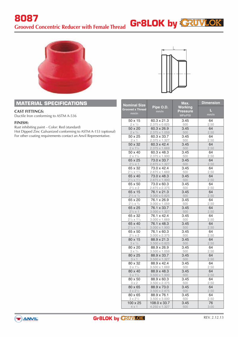
8087Grooved Concentric Reducer with Female Thread
Gr8LOK by
REV. 2.12.13Gr8LOK by
MATERIAL SPECIFICATIONS
CAST FITTINGS:
Ductile Iron conforming to ASTM A-536
FINISH:
Rust inhibiting paint – Color: Red (standard)Hot Dipped Zinc Galvanized conforming to ASTM A-153 (optional)For other coating requirements contact an Anvil Representative.
Nominal SizeGrooved x Thread
mm/in
Pipe O.D.mm/in
Max.WorkingPressure
MPa/PSI
Dimension
Lmm/in
50 x 15 60.3 x 21.3 3.45 64
2 x 1/2 2.375 x 0.825 500 2.50
50 x 20 60.3 x 26.9 3.45 64
2 x 3/4 2.375 x 1.059 500 2.50
50 x 25 60.3 x 33.7 3.45 64
2 x 1 2.375 x 1.327 500 2.50
50 x 32 60.3 x 42.4 3.45 64
2 x 11/4 2.375 x 1.669 500 2.50
50 x 40 60.3 x 48.3 3.45 64
2 x 11/2 2.375 x 1.900 500 2.50
65 x 25 73.0 x 33.7 3.45 64
21/2 x 1 2.875 x 1.327 500 2.50
65 x 32 73.0 x 42.4 3.45 64
21/2 x 11/4 2.875 x 1.669 500 2.50
65 x 40 73.0 x 48.3 3.45 64
21/2 x 11/2 2.875 x 1.900 500 2.50
65 x 50 73.0 x 60.3 3.45 64
21/2 x 2 2.875 x 2.375 500 2.50
65 x 15 76.1 x 21.3 3.45 64
21/2 x 1/2 3.000 x 0.825 500 2.50
65 x 20 76.1 x 26.9 3.45 64
21/2 x 3/4 3.000 x 1.059 500 2.50
65 x 25 76.1 x 33.7 3.45 64
21/2 x 1 3.000 x 1.327 500 2.50
65 x 32 76.1 x 42.4 3.45 64
21/2 x 11/4 3.000 x 1.669 500 2.50
65 x 40 76.1 x 48.3 3.45 64
21/2 x 11/2 3.000 x 1.900 500 2.50
65 x 50 76.1 x 60.3 3.45 64
21/2 x 2 3.000 x 2.375 500 2.50
80 x 15 88.9 x 21.3 3.45 64
3 x 1/2 3.500 x 0.825 500 2.50
80 x 20 88.9 x 26.9 3.45 64
3 x 3/4 3.500 x 1.059 500 2.50
80 x 25 88.9 x 33.7 3.45 64
3 x 1 3.500 x 1.327 500 2.50
80 x 32 88.9 x 42.4 3.45 64
3 x 11/4 3.500 x 1.669 500 2.50
80 x 40 88.9 x 48.3 3.45 64
3 x 11/2 3.500 x 1.900 500 2.50
80 x 50 88.9 x 60.3 3.45 64
3 x 2 3.500 x 2.375 500 2.50
80 x 65 88.9 x 73.0 3.45 64
3 x 21/2 3.500 x 2.875 500 2.50
80 x 65 88.9 x 76.1 3.45 64
3 x 21/2 3.500 x 3.000 500 2.50
100 x 25 108.0 x 33.7 3.45 76
4 x 1 4.250 x 1.327 500 3.00
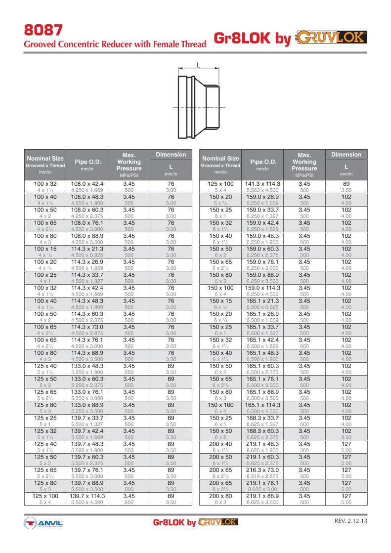
8087Grooved Concentric Reducer with Female Thread
Gr8LOK by
REV. 2.12.13Gr8LOK by
Nominal SizeGrooved x Thread
mm/in
Pipe O.D.mm/in
Max.WorkingPressure
MPa/PSI
Dimension
Lmm/in
100 x 32 108.0 x 42.4 3.45 76
4 x 11/4 4.250 x 1.669 500 3.00
100 x 40 108.0 x 48.3 3.45 76
4 x 11/2 4.250 x 1.900 500 3.00
100 x 50 108.0 x 60.3 3.45 76
4 x 2 4.250 x 2.375 500 3.00
100 x 65 108.0 x 76.1 3.45 76
4 x 21/2 4.250 x 3.000 500 3.00
100 x 80 108.0 x 88.9 3.45 76
4 x 3 4.250 x 3.500 500 3.00
100 x 15 114.3 x 21.3 3.45 76
4 x 1/2 4.500 x 0.825 500 3.00
100 x 20 114.3 x 26.9 3.45 76
4 x 3/4 4.500 x 1.059 500 3.00
100 x 25 114.3 x 33.7 3.45 76
4 x 1 4.500 x 1.327 500 3.00
100 x 32 114.3 x 42.4 3.45 76
4 x 11/4 4.500 x 1.669 500 3.00
100 x 40 114.3 x 48.3 3.45 76
4 x 11/2 4.500 x 1.900 500 3.00
100 x 50 114.3 x 60.3 3.45 76
4 x 2 4.500 x 2.375 500 3.00
100 x 65 114.3 x 73.0 3.45 76
4 x 21/2 4.500 x 2.875 500 3.00
100 x 65 114.3 x 76.1 3.45 76
4 x 21/2 4.500 x 3.000 500 3.00
100 x 80 114.3 x 88.9 3.45 76
4 x 3 4.500 x 3.500 500 3.00
125 x 40 133.0 x 48.3 3.45 89
5 x 11/2 5.250 x 1.900 500 3.50
125 x 50 133.0 x 60.3 3.45 89
5 x 2 5.250 x 2.375 500 3.50
125 x 65 133.0 x 76.1 3.45 89
5 x 21/2 5.250 x 3.000 500 3.50
125 x 80 133.0 x 88.9 3.45 89
5 x 3 5.250 x 3.500 500 3.50
125 x 25 139.7 x 33.7 3.45 89
5 x 1 5.500 x 1.327 500 3.50
125 x 32 139.7 x 42.4 3.45 89
5 x 11/4 5.500 x 1.669 500 3.50
125 x 40 139.7 x 48.3 3.45 89
5 x 11/2 5.500 x 1.900 500 3.50
125 x 50 139.7 x 60.3 3.45 89
5 x 2 5.500 x 2.375 500 3.50
125 x 65 139.7 x 76.1 3.45 89
5 x 21/2 5.500 x 3.000 500 3.50
125 x 80 139.7 x 88.9 3.45 89
5 x 3 5.500 x 3.500 500 3.50
125 x 100 139.7 x 114.3 3.45 89
5 x 4 5.500 x 4.500 500 3.50
Nominal SizeGrooved x Thread
mm/in
Pipe O.D.mm/in
Max.WorkingPressure
MPa/PSI
Dimension
Lmm/in
125 x 100 141.3 x 114.3 3.45 89
5 x 4 5.563 x 4.500 500 3.50
150 x 20 159.0 x 26.9 3.45 102
6 x 3/4 6.250 x 1.059 500 4.00
150 x 25 159.0 x 33.7 3.45 102
6 x 1 6.250 x 1.327 500 4.00
150 x 32 159.0 x 42.4 3.45 102
6 x 11/4 6.250 x 1.669 500 4.00
150 x 40 159.0 x 48.3 3.45 102
6 x 11/2 6.250 x 1.900 500 4.00
150 x 50 159.0 x 60.3 3.45 102
6 x 2 6.250 x 2.375 500 4.00
150 x 65 159.0 x 76.1 3.45 102
6 x 21/2 6.250 x 3.000 500 4.00
150 x 80 159.0 x 88.9 3.45 102
6 x 3 6.250 x 3.500 500 4.00
150 x 100 159.0 x 114.3 3.45 102
6 x 4 6.250 x 4.500 500 4.00
150 x 15 165.1 x 21.3 3.45 102
6 x 1/2 6.500 x 0.825 500 4.00
150 x 20 165.1 x 26.9 3.45 102
6 x 3/4 6.500 x 1.059 500 4.00
150 x 25 165.1 x 33.7 3.45 102
6 x 1 6.500 x 1.327 500 4.00
150 x 32 165.1 x 42.4 3.45 102
6 x 11/4 6.500 x 1.669 500 4.00
150 x 40 165.1 x 48.3 3.45 102
6 x 11/2 6.500 x 1.900 500 4.00
150 x 50 165.1 x 60.3 3.45 102
6 x 2 6.500 x 2.375 500 4.00
150 x 65 165.1 x 76.1 3.45 102
6 x 21/2 6.500 x 3.000 500 4.00
150 x 80 165.1 x 88.9 3.45 102
6 x 3 6.500 x 3.500 500 4.00
150 x 100 165.1 x 114.3 3.45 102
6 x 4 6.500 x 4.500 500 4.00
150 x 25 168.3 x 33.7 3.45 102
6 x 1 6.625 x 1.327 500 4.00
150 x 50 168.3 x 60.3 3.45 102
6 x 2 6.625 x 2.375 500 4.00
200 x 40 219.1 x 48.3 3.45 127
8 x 11/2 8.625 x 1.900 500 5.00
200 x 50 219.1 x 60.3 3.45 127
8 x 11/2 8.625 x 2.375 500 5.00
200 x 65 216.3 x 73.0 3.45 127
8 x 21/2 8.516 x 2.875 500 5.00
200 x 65 219.1 x 76.1 3.45 127
8 x 21/2 8.625 x 3.00 500 5.00
200 x 80 219.1 x 88.9 3.45 127
8 x 3 8.625 x 3.500 500 5.00

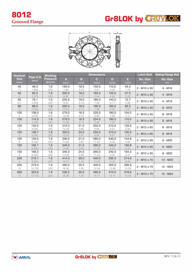
8012Grooved Flange Gr8LOK by
REV. 7.26.13Gr8LOK by
The Model 8012 Grooved Flange makes it possible for a direct connection of flanged components to a grooved piping system. The two interlocking halves of the Gr8LOK Grooved Flange are hinged for ease of handling, and are drawn together by a latch bolt which eases assembly on the pipe.
For the latest UL/ULC listed, LPCB, VdS and FM Approvedpressure ratings versus pipe schedule, contact your local Anvil Representative.
MATERIAL SPECIFICATIONS
HOUSING:Ductile Iron conforming to ASTM A-536, Grade 65-45-12
ANSI BOLTS & HEAVY HEX NUTS:Heat treated, oval-neck track head bolts conforming to SAE J429 Grade 5 with a minimum tensile strength of 120,000 psi and heavy hex nuts of carbon steel conforming to ASTM A-563 Grade A or B, or SAE J995 Grade 2. Bolts and nuts are provided zinc electroplated as standard.
METRIC BOLTS & HEAVY HEX NUTS:Heat treated, zinc electroplated oval-neck track head bolts made of carbon steel with mechanical properties per ISO 898-1 Class 8.8. Hex nuts and bolts are zinc electroplated followed by a yellow chromate dip.
COATINGS:Rust inhibiting paint – Color: Red (standard)Hot Dipped Zinc Galvanized (optional)For other coating requirements contact an Anvil Representative.
GASKETS
Properties as designated in accordance with ASTM D-2000
GRADE ”E” EPDM (Green Stripe)Working Temperature Range is -30°F to 230°F (-34°C to 110°C)Recommended for water service, diluted acids, alkalies solu-tions, oil-free air and many chemical services.
NOT FOR USE IN PETROLEUM APPLICATIONS OR WITH HYDROCARBONS.
8012Grooved Flange Gr8LOK by
REV. 7.26.13Gr8LOK by
Nominal Sizemm/in
Pipe O.D.mm/in
WorkingPressure
MPa/PSI
Dimensions Latch Bolt Mating Flange Bolt
Amm/in
Bmm/in
Cmm/in
Dmm/in
Emm/in
No.-Sizemm
No.-Sizemm
40 48.3 1.6 195.0 18.5 150.0 110.0 45.42 - M10 x 50 4 - M16
11/2 1.900 225 7.68 0.73 5.91 4.33 1.79
50 60.3 1.6 220.0 18.5 165.0 125.0 57.52 - M10 x 50 4 - M16
2 2.375 225 8.66 0.73 6.50 4.92 2.26
65 76.1 1.6 235.0 18.5 185.0 145.0 72.72 - M10 x 50 4 - M16
21/2 3.000 225 9.25 0.73 7.28 5.71 2.86
80 88.9 1.6 255.0 18.5 195.0 160.0 85.52 - M10 x 50 8 - M16
3 3.500 225 10.04 0.73 7.68 6.30 3.37
100 108.0 1.6 279.0 18.5 220.0 180.0 104.52 - M10 x 50 8 - M16
4 4.250 225 10.98 0.73 8.66 7.09 4.11
100 114.3 1.6 279.0 18.5 224.0 180.0 110.52 - M10 x 50 8 - M16
4 4.500 225 10.98 0.73 8.82 7.09 4.35
125 133.0 1.6 312.0 21.5 250.0 210.0 129.22 - M12 x 65 8 - M16
5 5.250 225 12.28 0.85 9.84 8.27 5.09
125 139.7 1.6 320.0 23.0 250.0 210.0 135.52 - M12 x 65 8 - M16
5 5.500 225 12.60 0.91 9.84 8.27 5.33
150 159.0 1.6 346.0 21.5 280.0 240.0 154.82 - M12 x 65 8 - M20
6 6.250 225 13.62 0.85 11.02 9.45 6.09
150 165.1 1.6 346.0 21.5 280.0 240.0 160.82 - M12 x 65 8 - M20
6 6.500 225 13.62 0.85 11.02 9.45 6.33
150 168.3 1.6 346.0 24.0 280.0 240.0 164.32 - M12 x 65 8 - M20
6 6.625 225 13.62 0.94 11.02 9.45 6.47
200 219.1 1.6 414.3 30.0 340.0 295.0 214.92 - M10 x 70 12 - M20
8 8.625 225 16.31 1.18 13.39 11.61 8.46
250 273.0 1.6 480.0 25.5 405.0 355.0 268.92 - M10 x 70 12 - M24
10 10.750 225 18.90 1.00 15.94 13.98 10.59
300 323.9 1.6 530.5 25.5 460.0 410.0 318.92 - M10 x 70 12 - M24
12 12.750 225 20.89 1.00 18.11 16.14 12.56
8012Grooved Flange Gr8LOK by
REV. 7.26.13Gr8LOK by
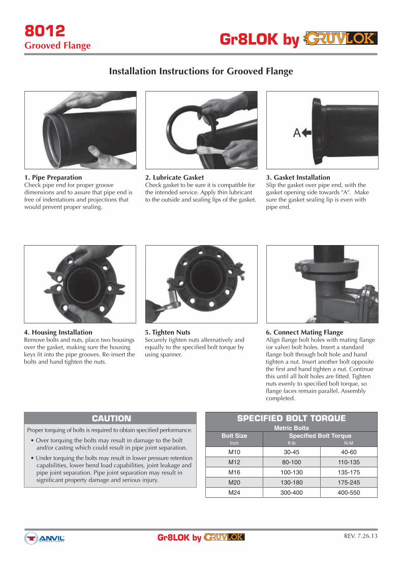
Installation Instructions for Grooved Flange
1. Pipe PreparationCheck pipe end for proper groove dimensions and to assure that pipe end is free of indentations and projections that would prevent proper sealing.
2. Lubricate GasketCheck gasket to be sure it is compatible for the intended service. Apply thin lubricant to the outside and sealing lips of the gasket.
3. Gasket InstallationSlip the gasket over pipe end, with the gasket opening side towards "A". Make sure the gasket sealing lip is even with pipe end.
4. Housing InstallationRemove bolts and nuts, place two housings over the gasket, making sure the housing keys fit into the pipe grooves. Re-insert the bolts and hand tighten the nuts.
CAUTION
Proper torquing of bolts is required to obtain specified performance.
and/or casting which could result in pipe joint separation.
capabilities, lower bend load capabilities, joint leakage and pipe joint separation. Pipe joint separation may result in significant property damage and serious injury.
SPECIFIED BOLT TORQUEMetric Bolts
Bolt Size Specified Bolt TorqueInch ft-lb N-M
M10 30-45 40-60
M12 80-100 110-135
M16 100-130 135-175
M20 130-180 175-245
M24 300-400 400-550
5. Tighten NutsSecurely tighten nuts alternatively and equally to the specified bolt torque by using spanner.
6. Connect Mating FlangeAlign flange bolt holes with mating flange (or valve) bolt holes. Insert a standard flange bolt through bolt hole and hand tighten a nut. Insert another bolt opposite the first and hand tighten a nut. Continue this until all bolt holes are fitted. Tighten nuts evenly to specified bolt torque, so flange faces remain parallel. Assembly completed.

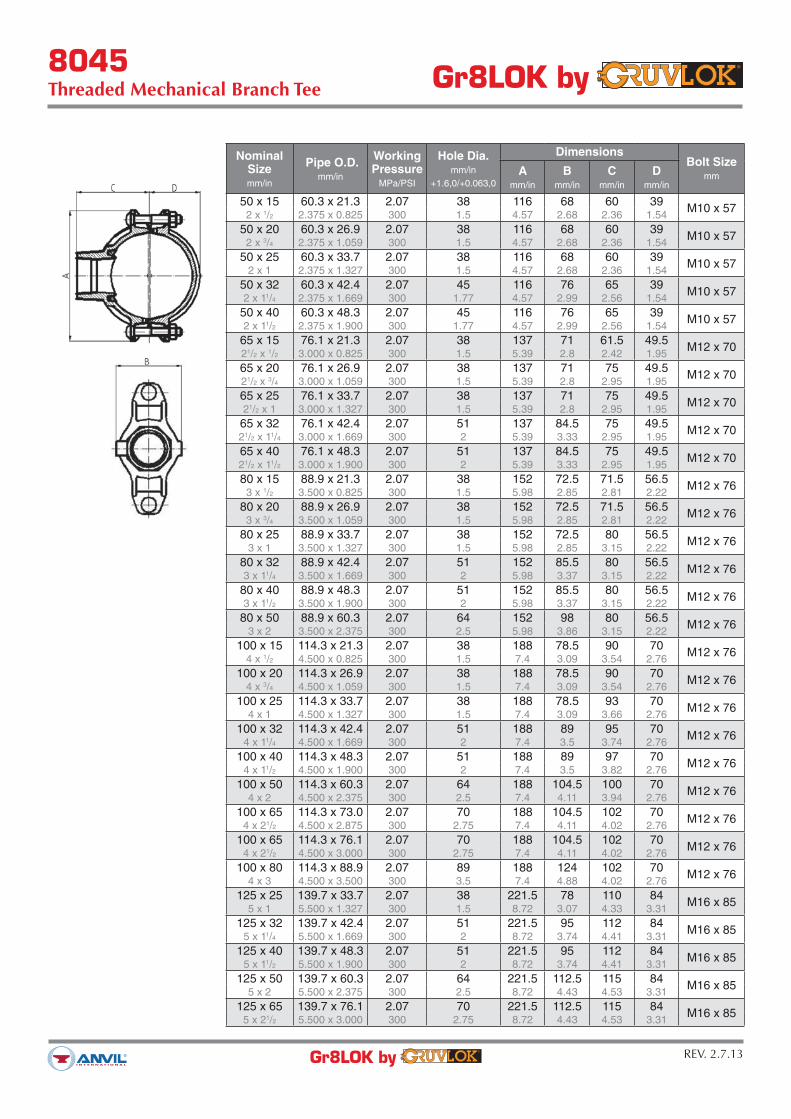
8045Threaded Mechanical Branch Tee Gr8LOK by
REV. 2.7.13Gr8LOK by
Mechanical branch connections for reducing branch outlets without welding. The 8045 is a bolted saddle type fitting with BSP female threaded outlets. Design assures superior sealing, full pipe support, excellent stability and easy installation.
For the latest UL/ULC listed, LPCB, VdS and FM Approvedpressure ratings versus pipe schedule, contact your local Anvil Representative.
MATERIAL SPECIFICATIONS
HOUSING:Ductile Iron conforming to ASTM A-536, Grade 65-45-12
ANSI BOLTS & HEAVY HEX NUTS:Heat treated, oval-neck track head bolts conforming to SAE J429 Grade 5 with a minimum tensile strength of 120,000 psi and heavy hex nuts of carbon steel conforming to ASTM A-563 Grade A or B, or SAE J995 Grade 2. Bolts and nuts are provided zinc electroplated as standard.
METRIC BOLTS & HEAVY HEX NUTS:Heat treated, zinc electroplated oval-neck track head bolts made of carbon steel with mechanical properties per ISO 898-1 Class 8.8. Hex nuts and bolts are zinc electroplated followed by a yellow chromate dip.
COATINGS:Rust inhibiting paint – Color: Red (standard)Hot Dipped Zinc Galvanized (optional)For other coating requirements contact an Anvil Representative.
GASKETS
Properties as designated in accordance with ASTM D-2000
GRADE ”E” EPDM (Green Stripe)Working Temperature Range is -30°F to 230°F (-34°C to 110°C)Recommended for water service, diluted acids, alkalies solutions, oil-free air and many chemical services.
NOT FOR USE IN PETROLEUM APPLICATIONS OR WITH HYDROCARBONS.
8045Threaded Mechanical Branch Tee Gr8LOK by
REV. 2.7.13Gr8LOK by
NominalSizemm/in
Pipe O.D.mm/in
WorkingPressure
MPa/PSI
Hole Dia.mm/in
+1.6,0/+0.063,0
DimensionsBolt Size
mmA
mm/in
Bmm/in
Cmm/in
Dmm/in
50 x 15 60.3 x 21.3 2.07 38 116 68 60 39M10 x 57
2 x 1/2 2.375 x 0.825 300 1.5 4.57 2.68 2.36 1.54
50 x 20 60.3 x 26.9 2.07 38 116 68 60 39M10 x 57
2 x 3/4 2.375 x 1.059 300 1.5 4.57 2.68 2.36 1.54
50 x 25 60.3 x 33.7 2.07 38 116 68 60 39M10 x 57
2 x 1 2.375 x 1.327 300 1.5 4.57 2.68 2.36 1.54
50 x 32 60.3 x 42.4 2.07 45 116 76 65 39M10 x 57
2 x 11/4 2.375 x 1.669 300 1.77 4.57 2.99 2.56 1.54
50 x 40 60.3 x 48.3 2.07 45 116 76 65 39M10 x 57
2 x 11/2 2.375 x 1.900 300 1.77 4.57 2.99 2.56 1.54
65 x 15 76.1 x 21.3 2.07 38 137 71 61.5 49.5M12 x 70
21/2 x 1/2 3.000 x 0.825 300 1.5 5.39 2.8 2.42 1.95
65 x 20 76.1 x 26.9 2.07 38 137 71 75 49.5M12 x 70
21/2 x 3/4 3.000 x 1.059 300 1.5 5.39 2.8 2.95 1.95
65 x 25 76.1 x 33.7 2.07 38 137 71 75 49.5M12 x 70
21/2 x 1 3.000 x 1.327 300 1.5 5.39 2.8 2.95 1.95
65 x 32 76.1 x 42.4 2.07 51 137 84.5 75 49.5M12 x 70
21/2 x 11/4 3.000 x 1.669 300 2 5.39 3.33 2.95 1.95
65 x 40 76.1 x 48.3 2.07 51 137 84.5 75 49.5M12 x 70
21/2 x 11/2 3.000 x 1.900 300 2 5.39 3.33 2.95 1.95
80 x 15 88.9 x 21.3 2.07 38 152 72.5 71.5 56.5M12 x 76
3 x 1/2 3.500 x 0.825 300 1.5 5.98 2.85 2.81 2.22
80 x 20 88.9 x 26.9 2.07 38 152 72.5 71.5 56.5M12 x 76
3 x 3/4 3.500 x 1.059 300 1.5 5.98 2.85 2.81 2.22
80 x 25 88.9 x 33.7 2.07 38 152 72.5 80 56.5M12 x 76
3 x 1 3.500 x 1.327 300 1.5 5.98 2.85 3.15 2.22
80 x 32 88.9 x 42.4 2.07 51 152 85.5 80 56.5M12 x 76
3 x 11/4 3.500 x 1.669 300 2 5.98 3.37 3.15 2.22
80 x 40 88.9 x 48.3 2.07 51 152 85.5 80 56.5M12 x 76
3 x 11/2 3.500 x 1.900 300 2 5.98 3.37 3.15 2.22
80 x 50 88.9 x 60.3 2.07 64 152 98 80 56.5M12 x 76
3 x 2 3.500 x 2.375 300 2.5 5.98 3.86 3.15 2.22
100 x 15 114.3 x 21.3 2.07 38 188 78.5 90 70M12 x 76
4 x 1/2 4.500 x 0.825 300 1.5 7.4 3.09 3.54 2.76
100 x 20 114.3 x 26.9 2.07 38 188 78.5 90 70M12 x 76
4 x 3/4 4.500 x 1.059 300 1.5 7.4 3.09 3.54 2.76
100 x 25 114.3 x 33.7 2.07 38 188 78.5 93 70M12 x 76
4 x 1 4.500 x 1.327 300 1.5 7.4 3.09 3.66 2.76
100 x 32 114.3 x 42.4 2.07 51 188 89 95 70M12 x 76
4 x 11/4 4.500 x 1.669 300 2 7.4 3.5 3.74 2.76
100 x 40 114.3 x 48.3 2.07 51 188 89 97 70M12 x 76
4 x 11/2 4.500 x 1.900 300 2 7.4 3.5 3.82 2.76
100 x 50 114.3 x 60.3 2.07 64 188 104.5 100 70M12 x 76
4 x 2 4.500 x 2.375 300 2.5 7.4 4.11 3.94 2.76
100 x 65 114.3 x 73.0 2.07 70 188 104.5 102 70M12 x 76
4 x 21/2 4.500 x 2.875 300 2.75 7.4 4.11 4.02 2.76
100 x 65 114.3 x 76.1 2.07 70 188 104.5 102 70M12 x 76
4 x 21/2 4.500 x 3.000 300 2.75 7.4 4.11 4.02 2.76
100 x 80 114.3 x 88.9 2.07 89 188 124 102 70M12 x 76
4 x 3 4.500 x 3.500 300 3.5 7.4 4.88 4.02 2.76
125 x 25 139.7 x 33.7 2.07 38 221.5 78 110 84M16 x 85
5 x 1 5.500 x 1.327 300 1.5 8.72 3.07 4.33 3.31
125 x 32 139.7 x 42.4 2.07 51 221.5 95 112 84M16 x 85
5 x 11/4 5.500 x 1.669 300 2 8.72 3.74 4.41 3.31
125 x 40 139.7 x 48.3 2.07 51 221.5 95 112 84M16 x 85
5 x 11/2 5.500 x 1.900 300 2 8.72 3.74 4.41 3.31
125 x 50 139.7 x 60.3 2.07 64 221.5 112.5 115 84M16 x 85
5 x 2 5.500 x 2.375 300 2.5 8.72 4.43 4.53 3.31
125 x 65 139.7 x 76.1 2.07 70 221.5 112.5 115 84M16 x 85
5 x 21/2 5.500 x 3.000 300 2.75 8.72 4.43 4.53 3.31

8045Threaded Mechanical Branch Tee Gr8LOK by
REV. 2.7.13Gr8LOK by
NominalSizemm/in
Pipe O.D.mm/in
WorkingPressure
MPa/PSI
Hole Dia.mm/in
+1.6,0/+0.063,0
DimensionsBolt Size
mmA
mm/in
Bmm/in
Cmm/in
Dmm/in
125 x 80 139.7 x 88.9 2.07 89 221.5 132 120 84M16 x 85
5 x 3 5.500 x 3.500 300 3.5 8.72 5.2 4.72 3.31
125 x 100 139.7 x 114.3 2.07 114 221.5 156 125 84M16 x 85
5 x 4 5.500 x 4.500 300 4.5 8.72 6.1 4.92 3.31
150 x 15 165.1 x 21.3 2.07 38 244 78 110 97.5M16 x 108
6 x 1/2 6.500 x 0.825 300 1.5 9.6 3.07 4.33 3.84
150 x 20 165.1 x 26.9 2.07 38 244 78 110 97.5M16 x 108
6 x 3/4 6.500 x 1.059 300 1.5 9.6 3.07 4.33 3.84
150 x 25 165.1 x 33.7 2.07 38 244 78 118 97.5M16 x 108
6 x 1 6.500 x 1.327 300 1.5 9.6 3.07 4.65 3.84
150 x 32 165.1 x 42.4 2.07 51 244 93 118 97.5M16 x 108
6 x 11/4 6.500 x 1.669 300 2 9.6 3.66 4.65 3.84
150 x 40 165.1 x 48.3 2.07 51 244 93 118 97.5M16 x 108
6 x 11/2 6.500 x 1.900 300 2 9.6 3.66 4.65 3.84
150 x 50 165.1 x 60.3 2.07 64 244 112.5 128.5 97.5M16 x 108
6 x 2 6.500 x 2.375 300 2.5 9.6 4.43 5.06 3.84
150 x 65 165.1 x 76.1 2.07 70 244 112.5 128.5 97.5M16 x 108
6 x 21/2 6.500 x 3.000 300 2.75 9.6 4.43 5.06 3.84
150 x 80 165.1 x 88.9 2.07 89 244 132 128.5 97.5M16 x 108
6 x 3 6.500 x 3.500 300 3.5 9.6 5.2 5.06 3.84
150 x 100 165.1 x 114.3 2.07 114 244 154 135 97.5M16 x 108
6 x 4 6.500 x 4.500 300 4.5 9.6 6.06 5.32 3.84
150 x 32 168.3 x 42.4 2.07 51 247 95 130 98.5M16 x 108
6 x 11/4 6.625 x 1.669 300 2 9.72 3.74 5.12 3.88
150 x 40 168.3 x 48.3 2.07 51 247 95 122 98.5M16 x 108
6 x 11/2 6.625 x 1.900 300 2 9.72 3.74 4.8 3.88
150 x 50 168.3 x 60.3 2.07 64 247 112.5 132 98.5M16 x 108
6 x 2 6.625 x 2.375 300 2.5 9.72 4.43 5.2 3.88
150 x 65 168.3 x 73.0 2.07 70 247 112.5 132 98.5M16 x 108
6 x 21/2 6.625 x 2.875 300 2.75 9.72 4.43 5.2 3.88
150 x 80 168.3 x 88.9 2.07 89 247 132 140 98.5M16 x 108
6 x 3 6.625 x 3.500 300 3.5 9.72 5.2 5.51 3.88
150 x 100 168.3 x 114.3 2.07 114 247 156.5 140 98.5M16 x 108
6 x 4 6.625 x 4.500 300 4.5 9.72 6.16 5.51 3.88
200 x 25 219.1 x 33.7 2.07 38 322 79.5 150 125M20 x 115
8 x 1 8.625 x 1.327 300 1.5 12.68 3.13 5.91 4.92
200 x 32 219.1 x 42.4 2.07 51 320 96.5 150 125M20 x 115
8 x 11/4 8.625 x 1.669 300 2 12.60 3.8 5.91 4.92
200 x 40 219.1 x 48.3 2.07 51 320 96.5 150 125M20 x 115
8 x 11/2 8.625 x 1.900 300 2 12.60 3.8 5.91 4.92
200 x 50 219.1 x 60.3 2.07 64 322 117 160 125M20 x 115
8 x 2 8.625 x 2.375 300 2.5 12.68 4.61 6.3 4.92
200 x 65 219.1 x 76.1 2.07 70 322 118 158.5 125M20 x 115
8 x 21/2 8.625 x 3.000 300 2.75 12.68 4.65 6.24 4.92
200 x 80 219.1 x 88.9 2.07 89 322 136.5 160 125M20 x 115
8 x 3 8.625 x 3.500 300 3.5 12.68 5.37 6.3 4.92
200 x 100 219.1 x 114.3 2.07 114 322 164 160 125M20 x 115
8 x 4 8.625 x 4.500 300 4.5 12.68 6.46 6.3 4.92
250 x 40 273.0 x 48.3 2.07 51 376 95.5 180 155M20 x 115
10 x 11/2 10.750 x 1.900 300 2 14.8 3.76 7.09 6.1
250 x 50 273.0 x 60.3 2.07 64 376 118 185 155M20 x 115
10 x 2 10.750 x 2.375 300 2.5 14.8 4.65 7.28 6.1
250 x 65 273.0 x 76.1 2.07 70 376 118 190 155M20 x 115
10 x 21/2 10.750 x 3.000 300 2.75 14.8 4.65 7.48 6.1
250 x 80 273.0 x 88.9 2.07 89 376 136.5 190 155M20 x 115
10 x 3 10.750 x 3.500 300 3.5 14.8 5.37 7.48 6.1
250 x 100 273.0 x 114.3 2.07 114 376 164 190 155M20 x 115
10 x 4 10.750 x 4.500 300 4.5 14.8 6.46 7.48 6.1

8045Threaded Mechanical Branch Tee Gr8LOK by
REV. 2.7.13Gr8LOK by
Installation Instructions for Threaded Mechanical Tees
1. Pipe PreparationCut the appropriate size hole in the pipe and remove any burrs. Be sure to remove the slug from inside the pipe. Clean the gasket sealing surface within 16 mm of the hole and visually inspect the sealing surface for defects that may prevent proper sealing of the gasket.
2. Check & Lubricate GasketCheck the gasket to be sure it is compatible for the intended service. Apply a thin layer of Gruvlok lubricant to the back surface of the gasket. Be careful that foreign particles do not adhere to the lubricated surfaces. Insert the gasket back into the outlet housing making sure the tabs in the gasket line up with the tab recesses in the housing.
3. Gasket InstallationLubricate the exposed surface of the gasket. Align the outlet housing over the pipe hole making sure that the locating collar is in the pipe hole.
4. AlignmentAlign the strap around the pipe, insert the bolts and tighten the nuts finger tight.
SPECIFIED BOLT TORQUEANSI Bolts
Bolt Size Specified Bolt TorqueInch ft-lb N-M
3⁄8 30-45 40-60
1⁄2 80-100 110-135
5⁄8 100-130 135-175
3⁄4 – –
7⁄8 – –
5. Tighten NutsAlternately and evenly tighten the nuts to the specified bolt torque.
6. Assembly CompletedThere should be even gaps on two sides between upper and lower housing.
CAUTION
Proper torquing of bolts is required to obtain specified performance.
torque output can vary significantly due to many variables including air pressure supply, battery strength and operational variations.
and/or casting which could result in pipe joint separation.
retention capabilities, lower bend load capabilities, joint leakage and pipe joint separation. Pipe joint separation may result in significant property damage and serious injury.

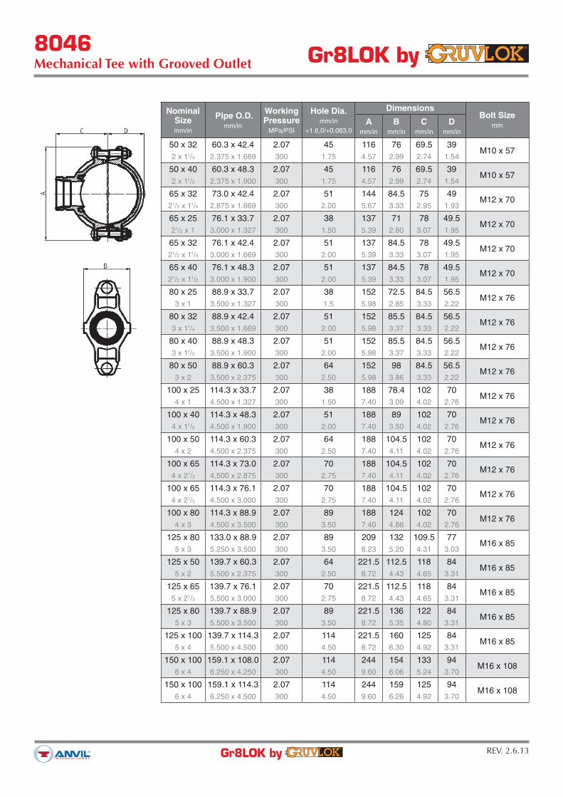
8046Mechanical Tee with Grooved Outlet Gr8LOK by
REV. 2.6.13Gr8LOK by
Mechanical branch connections for reducing branch outlets without welding. The 8046 is a bolted saddle type fitting with grooved outlets. Design assures superior sealing, full pipe support, excellent stability and easy installation.
For the latest UL/ULC listed, LPCB, VdS and FM Approvedpressure ratings versus pipe schedule, contact your local Anvil Representative.
MATERIAL SPECIFICATIONS
HOUSING:Ductile Iron conforming to ASTM A-536, Grade 65-45-12
ANSI BOLTS & HEAVY HEX NUTS:Heat treated, oval-neck track head bolts conforming to SAE J429 Grade 5 with a minimum tensile strength of 120,000 psi and heavy hex nuts of carbon steel conforming to ASTM A-563 Grade A or Grade B, or SAE J995 Grade 2. Bolts and nuts are provided zinc electroplated as standard.
METRIC BOLTS & HEAVY HEX NUTS:Heat treated, zinc electroplated oval-neck track head bolts made of carbon steel with mechanical properties per ISO 898-1 Class 8.8. Hex nuts and bolts are zinc electroplated followed by a yellow chromate dip.
COATINGS:Rust inhibiting paint – Color: Red (standard)Hot Dipped Zinc Galvanized (optional)For other coating requirements contact an Anvil Representative.
GASKETS
Properties as designated in accordance with ASTM D-2000
GRADE ”E” EPDM (Green Stripe)Working Temperature Range is -30°F to 230°F (-34°C to 110°C)Recommended for water service, diluted acids, alkalies solutions, oil-free air and many chemical services.
NOT FOR USE IN PETROLEUM APPLICATIONS OR WITH HYDROCARBONS.
8046Mechanical Tee with Grooved Outlet Gr8LOK by
REV. 2.6.13Gr8LOK by
NominalSizemm/in
Pipe O.D.mm/in
WorkingPressure
MPa/PSI
Hole Dia.mm/in
+1.6,0/+0.063,0
DimensionsBolt Size
mmA
mm/in
Bmm/in
Cmm/in
Dmm/in
50 x 32 60.3 x 42.4 2.07 45 116 76 69.5 39M10 x 57
2 x 11/4 2.375 x 1.669 300 1.75 4.57 2.99 2.74 1.54
50 x 40 60.3 x 48.3 2.07 45 116 76 69.5 39M10 x 57
2 x 11/2 2.375 x 1.900 300 1.75 4.57 2.99 2.74 1.54
65 x 32 73.0 x 42.4 2.07 51 144 84.5 75 49M12 x 70
21/2 x 11/4 2.875 x 1.669 300 2.00 5.67 3.33 2.95 1.93
65 x 25 76.1 x 33.7 2.07 38 137 71 78 49.5M12 x 70
21/2 x 1 3.000 x 1.327 300 1.50 5.39 2.80 3.07 1.95
65 x 32 76.1 x 42.4 2.07 51 137 84.5 78 49.5M12 x 70
21/2 x 11/4 3.000 x 1.669 300 2.00 5.39 3.33 3.07 1.95
65 x 40 76.1 x 48.3 2.07 51 137 84.5 78 49.5M12 x 70
21/2 x 11/2 3.000 x 1.900 300 2.00 5.39 3.33 3.07 1.95
80 x 25 88.9 x 33.7 2.07 38 152 72.5 84.5 56.5M12 x 76
3 x 1 3.500 x 1.327 300 1.5 5.98 2.85 3.33 2.22
80 x 32 88.9 x 42.4 2.07 51 152 85.5 84.5 56.5M12 x 76
3 x 11/4 3.500 x 1.669 300 2.00 5.98 3.37 3.33 2.22
80 x 40 88.9 x 48.3 2.07 51 152 85.5 84.5 56.5M12 x 76
3 x 11/2 3.500 x 1.900 300 2.00 5.98 3.37 3.33 2.22
80 x 50 88.9 x 60.3 2.07 64 152 98 84.5 56.5M12 x 76
3 x 2 3.500 x 2.375 300 2.50 5.98 3.86 3.33 2.22
100 x 25 114.3 x 33.7 2.07 38 188 78.4 102 70M12 x 76
4 x 1 4.500 x 1.327 300 1.50 7.40 3.09 4.02 2.76
100 x 40 114.3 x 48.3 2.07 51 188 89 102 70M12 x 76
4 x 11/2 4.500 x 1.900 300 2.00 7.40 3.50 4.02 2.76
100 x 50 114.3 x 60.3 2.07 64 188 104.5 102 70M12 x 76
4 x 2 4.500 x 2.375 300 2.50 7.40 4.11 4.02 2.76
100 x 65 114.3 x 73.0 2.07 70 188 104.5 102 70M12 x 76
4 x 21/2 4.500 x 2.875 300 2.75 7.40 4.11 4.02 2.76
100 x 65 114.3 x 76.1 2.07 70 188 104.5 102 70M12 x 76
4 x 21/2 4.500 x 3.000 300 2.75 7.40 4.11 4.02 2.76
100 x 80 114.3 x 88.9 2.07 89 188 124 102 70M12 x 76
4 x 3 4.500 x 3.500 300 3.50 7.40 4.88 4.02 2.76
125 x 80 133.0 x 88.9 2.07 89 209 132 109.5 77M16 x 85
5 x 3 5.250 x 3.500 300 3.50 8.23 5.20 4.31 3.03
125 x 50 139.7 x 60.3 2.07 64 221.5 112.5 118 84M16 x 85
5 x 2 5.500 x 2.375 300 2.50 8.72 4.43 4.65 3.31
125 x 65 139.7 x 76.1 2.07 70 221.5 112.5 118 84M16 x 85
5 x 21/2 5.500 x 3.000 300 2.75 8.72 4.43 4.65 3.31
125 x 80 139.7 x 88.9 2.07 89 221.5 136 122 84M16 x 85
5 x 3 5.500 x 3.500 300 3.50 8.72 5.35 4.80 3.31
125 x 100 139.7 x 114.3 2.07 114 221.5 160 125 84M16 x 85
5 x 4 5.500 x 4.500 300 4.50 8.72 6.30 4.92 3.31
150 x 100 159.1 x 108.0 2.07 114 244 154 133 94M16 x 108
6 x 4 6.250 x 4.250 300 4.50 9.60 6.06 5.24 3.70
150 x 100 159.1 x 114.3 2.07 114 244 159 125 94M16 x 108
6 x 4 6.250 x 4.500 300 4.50 9.60 6.26 4.92 3.70

8046Mechanical Tee with Grooved Outlet Gr8LOK by
REV. 2.6.13Gr8LOK by
NominalSizemm/in
Pipe O.D.mm/in
WorkingPressure
MPa/PSI
Hole Dia.mm/in
+1.6,0/+0.063,0
DimensionsBolt Size
mmA
mm/in
Bmm/in
Cmm/in
Dmm/in
150 x 50 165.1 x 60.3 2.07 64 244 112.5 127 97.5M16 x 108
6 x 2 6.500 x 2.375 300 2.50 9.60 4.43 5.00 3.84
150 x 65 165.1 x 76.1 2.07 70 244 112.5 127 97.5M16 x 108
6 x 21/2 6.500 x 3.000 300 2.75 9.60 4.43 5.00 3.84
150 x 80 165.1 x 88.9 2.07 89 244 132 141 97.5M16 x 108
6 x 3 6.500 x 3.500 300 3.50 9.60 5.20 5.55 3.84
150 x 100 165.1 x 114.3 2.07 114 244 154 135 97.5M16 x 108
6 x 4 6.500 x 4.500 300 4.50 9.60 6.06 5.32 3.84
150 x 40 168.3 x 48.3 2.07 51 247 95 128 98.5M16 x 108
6 x 11/2 6.625 x 1.900 300 2.00 9.72 3.74 5.04 3.88
150 x 50 168.3 x 60.3 2.07 64 247 114 134 98.5M16 x 108
6 x 2 6.625 x 2.375 300 2.50 9.72 4.49 5.28 3.88
150 x 65 168.3 x 73.0 2.07 70 247 115 134 98.5M16 x 108
6 x 21/2 6.625 x 2.875 300 2.75 9.72 4.53 5.28 3.88
150 x 80 168.3 x 88.9 2.07 89 247 132 141 98.5M16 x 108
6 x 3 6.625 x 3.500 300 3.50 9.72 5.20 5.55 3.88
150 x 100 168.3 x 114.3 2.07 114 247 156.5 138 98.5M16 x 108
6 x 4 6.625 x 4.500 300 4.50 9.72 6.16 5.43 3.88
200 x 50 219.1 x 60.3 2.07 64 322 118 158 125M20 x 115
8 x 2 8.625 x 2.375 300 2.50 12.68 4.65 6.22 4.92
200 x 65 219.1 x 76.1 2.07 70 322 118 158 125M20 x 115
8 x 21/2 8.625 x 3.000 300 2.75 12.68 4.65 6.22 4.92
200 x 80 219.1 x 88.9 2.07 89 322 136.5 161 125M20 x 115
8 x 3 8.625 x 3.500 300 3.50 12.68 5.37 6.34 4.92
200 x 100 219.1 x 114.3 2.07 114 322 164 161 125M20 x 115
8 x 4 8.625 x 4.500 300 4.50 12.68 6.46 6.34 4.92
250 x 100 273.0 x 114.3 2.07 114 376 164 189 155M20 x 115
10 x 4 10.750 x 4.500 300 4.50 14.80 6.46 7.44 6.10
8046Mechanical Tee with Grooved Outlet Gr8LOK by
REV. 2.6.13Gr8LOK by
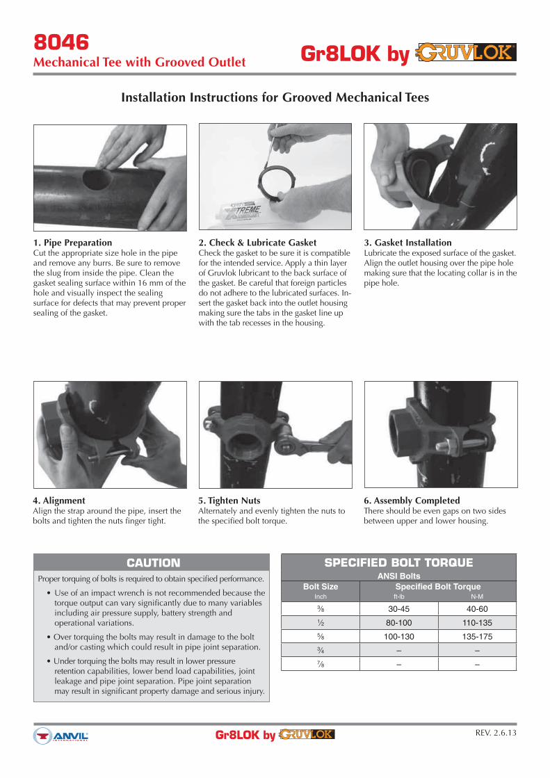
Installation Instructions for Grooved Mechanical Tees
1. Pipe PreparationCut the appropriate size hole in the pipe and remove any burrs. Be sure to remove the slug from inside the pipe. Clean the gasket sealing surface within 16 mm of the hole and visually inspect the sealing surface for defects that may prevent proper sealing of the gasket.
2. Check & Lubricate GasketCheck the gasket to be sure it is compatible for the intended service. Apply a thin layer of Gruvlok lubricant to the back surface of the gasket. Be careful that foreign particles do not adhere to the lubricated surfaces. In-sert the gasket back into the outlet housing making sure the tabs in the gasket line up with the tab recesses in the housing.
3. Gasket InstallationLubricate the exposed surface of the gasket. Align the outlet housing over the pipe hole making sure that the locating collar is in the pipe hole.
4. AlignmentAlign the strap around the pipe, insert the bolts and tighten the nuts finger tight.
SPECIFIED BOLT TORQUEANSI Bolts
Bolt Size Specified Bolt TorqueInch ft-lb N-M
3⁄8 30-45 40-60
1⁄2 80-100 110-135
5⁄8 100-130 135-175
3⁄4 – –
7⁄8 – –
5. Tighten NutsAlternately and evenly tighten the nuts to the specified bolt torque.
6. Assembly CompletedThere should be even gaps on two sides between upper and lower housing.
CAUTION
Proper torquing of bolts is required to obtain specified performance.
torque output can vary significantly due to many variables including air pressure supply, battery strength and operational variations.
and/or casting which could result in pipe joint separation.
retention capabilities, lower bend load capabilities, joint leakage and pipe joint separation. Pipe joint separation may result in significant property damage and serious injury.

TECHNICAL DATA
GRUVLOK
WATER & AIR
Service Gasket Grade
E/EP
L
T
E/EP/T
E
Water, Acid Mine E/T
Water, Chlorine
Water, Deionized E/EP/T
Water, Seawater E/EP/T
Water, Waste E/EP/T
Water, Lime E/EP/T
STANDARD GASKETS
GradeTemp. Range
CompoundColor Code
General Service Applications
E
-40°F to
+230°F
110°C)
EPDM Green
Water, dilute acids, alkalies, salts, and many chemical
services not involving hydrocarbons, oils, or gases.
Excellent oxidation resistance.
NOT FOR USE WITH HYDROCARBONS
EP
-40°F to
+250°F
121°C)
EPDMGreen
and Red
Water, dilute acids, alkalies, salts, and many chemical
services not involving hydrocarbons, oils, or gases.
Excellent oxidation resistance.
NOT FOR USE WITH HYDROCARBONS
T
-20°F to
+180°F
82°C)
Nitrile Petroleum products, vegetable oils, mineral
oils, and air contaminated with petroleum oils.
NOT FOR USE IN HOT WATER SERVICES
GASKET GRADE INDEX & GASKET
RECOMMENDATION
GASKET GRADE INDEX
GASKET RECOMMENDATION LISTING
VACUUM SERVICE
Where more than one gasket grade is shown the preferred gasket grade is listed first. Where the
gasket grade is shown in parentheses, Contact an Anvil Representative for an engineering evaluation
and recommendation. Specify gasket grade when ordering. Use Gruvlok lubricant on gasket. Check
gasket color code to be certain it is recommended for the service intended.
service conditions.
For services not listed, contact an Anvil Representative for recommendation.
*Contact an Anvil Representative for service evaluation.
LARGER SIZES: Contact an Anvil
Representative for more information.
SPECIAL GASKETS
GradeTemp. Range
CompoundColor Code
General Service Applications
O
+20°F to
+300°F
149°C)
Fluoro Elastomer
BlueHigh temperature resistance to oxidizing acids,
petroleum oils, hydraulic fluids, halogenated,
hydrocarbons and lubricants
L
-40°F to
+350°F
177°C)
SiliconeRed
GasketDry, hot air and some high temperature chemical
services.
E Type
A
-40°F to
+150°F
66°C)
Pre- Lubricated
Violet
Systems. For dry pipe systems, Gruvlok Xtreme™
Temperature Lubricant is required.
PETROLEUM PRODUCTS
Service Gasket Grade
T
T
T
Gasoline, Leaded T
Gasoline, Unleaded*
T
JP-3, JP-4 and JP-5
Kerosene T
T
T
T
Transmission Fluid —Type A
VACUUM SERVICE
Size Vacuum Level Gasket Recommendation
0" - 10" Hg Standard or Flush Gap
11⁄2 10" - 29.9" Hg Flush Gap
The lists are provided as an aid in selecting the optimum gasket grade for a specific application to assure the maximum service life.
The recommendations have been developed from current information supplied by manufacturers of the elastomers, technical publications, and industry applications. The information supplied should be considered as a basis for evaluation but not as a guarantee.
Selection of the optimum gasket grade for a specific service requires the consideration of many factors; primarily temperature, fluid concentration, and continuity of service. Unless otherwise noted, all gasket recommendations are based on 100°F (38°C) maximum temperature service condition. Where more than one gasket grade is shown, the preferred grade is listed first.
Combinations of fluids should be referred to an Anvil Representative for an engineering evaluation and recommendation. In unusual or severe services, gasket materials should be subjected to simulated service conditions to determine the most suitable gasket grade.
Gasket recommendations apply only to Gruvlok gaskets. Contact an Anvil Representative for recommendations for services not listed. These listings
do not apply to Gruvlok Butterfly Valves.
All Gruvlok products marked with UL/ULC Listed, FM approved VdS and/or LPC
symbols are Listed/Approved with EPDM material. For other Listed/Approved
materials, please contact an Anvil Representative for more information.


Gr8LOK Standard Roll Groove Specificationfor VDS - Approved Product Applications Gr8LOK by
REV. 7.11.13Gr8LOK by
Groove Diameter
TABLE 1: GR8LOK STANDARD ROLL GROOVE SPECIFICATION
FOR VDS - APPROVED PRODUCT APPLICATIONS
-1- -2- -3- -4- -5- -6- -7- -8- -9-
DN(mm) mm mm mm mm mm mm mm mm mm mm mm
25 33.7 +0.41 -0.68 15.88 7.14 30.23 -0.38 1.60 1.5 1.8 34.5
(1 in.)
32 42.4 +0.54 -0.61 15.88 7.14 38.99 -0.38 1.60 1.5 1.8 43.3
(11/4 in.)
40 48.3 +0.48 -0.48 15.88 7.14 45.09 -0.38 1.60 1.5 1.8 49.4
(11/2 in.)
50 60.3 +0.61 -0.61 15.88 8.74 57.15 -0.38 1.60 2.0 1.8 62.2
(2 in.)
65 76.1 +0.76 -0.76 15.88 8.74 72.26 -0.46 1.93 2.0 2.3 77.7
(3 in. OD)
80 88.9 +0.89 -0.79 15.88 8.74 84.94 -0.46 1.98 2.0 2.3 90.6
(3 in.)
100 114.3 +1.14 -0.79 15.88 8.74 110.08 -0.51 2.11 2.0 2.3 116.2
(4 in.)
125 139.7 +1.40 -0.79 15.88 8.74 135.48 -0.51 2.11 2.0 2.9 141.7
(51/2 in. OD)
150 168.3 +1.60 -0.79 15.88 8.74 163.96 -0.56 2.16 2.0 2.9 170.7
(6 in.)
200 219.1 +1.60 -0.79 19.05 11.91 214.40 -0.64 2.34 2.5 2.9 221.5
(8 in.)
250 273.1 +1.60 -0.79 19.05 11.91 268.27 -0.69 2.39 2.5 3.6 275.4
(10 in.)
300 323.9 +1.60 -0.79 19.05 11.91 318.29 -0.76 2.77 2.5 4.0 326.2
(12 in.)
Nominal
IPS Pipe
Size
Pipe OD
Actual Tolerance
“C”
Actual “C” Tol.
+0.000
Actual
Groove
Depth
“D”
(Ref. Only)
Groove
Corner
“E”
(max)
Min.
Allow.
Wall
Thick.
“T”
Max.
Flare
Dia.
Gasket
Seat
“A” +0.76
Groove
Width
“B” +0.76
COLUMN 1
Nominal IPS Pipe Size.
COLUMN 2
IPS outside diameter.
COLUMN 3
Gasket seat must be free from
scores, seams, chips, rust or scale
which may interfere with proper
sealing of the gasket. Gasket seat
width is to be measured from the
pipe end to the vertical flank in the
groove wall.
COLUMN 4
Groove width is to be measured
between vertical flank of the groove
size walls.
COLUMN 5
The groove must be uniform depth
around the entire pipe circumference.
(See column 6).
COLUMN 6
Groove depth: for reference only.
Groove must conform to the groove
diameter “C” listed in column 5.
COLUMN 7
Groove Corner “E”: the distance
between points (1) and (2) as
indicated in the illustration above.
Dimension “E” starts at the
reduction of pipe outside diameter
(O.D.) (point 1) and ends at the
bottom of the groove (point 2).
COLUMN 8
Minimum allowable wall thickness
which may be roll grooved.
COLUMN 9
Maximum allowable pipe end flare
diameter. Measured at the most
extreme pipe end diameter of the
gasket seat area.
NOTES
Out of roundness: Difference between maximum OD and minimum OD measured at 90° must not exceed
total OD tolerance listed.
Square cut ends: the maximum allowable tolerance from square cut ends is 0.76 mm for sizes 25mm-80mm;
1.15mm for sizes 100mm-150mm; and 1.52mm for sizes 200mm and above, measured from a true square line.
Beveled End Pipe in conformance with ANSI B16.25 (371/2°) is acceptable, however square cut is preferred.
Weld Seams must be ground flush with the pipe OD and ID prior to roll grooving. Failure to do so may
result in damage to the roll grooving machine and unacceptable roll grooves may be produced.

Gr8LOK Standard Roll Groove Specificationfor VDS - Approved Product Applications Gr8LOK by
REV. 7.11.13Gr8LOK by
Step 1Measure groove with a diameter tape or
a circummeter to ensure that the Groove
Diameter “C” is within the tolerance specified in
column 5, Table 1.
Step 2Using a ruler, measure the Gasket Seat length
“A”, Groove Width “B”, and Groove Corner “E”.
The Gasket Seat length “A” and Groove Width
“B” must be within the tolerance specified in
Table 1. Groove Corner “E” must not exceed the
dimension given in Table 1.
STEPS TO VERIFYING A PROPER ROLL GROOVE