building energy codes program · building energy codes program – energy codes and standards set...
TRANSCRIPT

BUILDING ENERGY CODES PROGRAM www.energycodes.gov
BUILDING ENERGY CODES PROGRAM
PNNL-SA-133052
2018 IECC Commercial Mechanical Requirements
BUILDING ENERGY CODES PROGRAM www.energycodes.gov
– Energy codes and standards set minimum efficiency requirements for new and renovated buildings, assuring reductions in energy use and emissions over the life of the building. Energy codes are a subset of building codes, which establish baseline requirements and govern building construction.
– Code buildings are more comfortable and cost-effective to operate, assuring energy, economic and environmental benefits.
Why Care About IECC?

BUILDING ENERGY CODES PROGRAM www.energycodes.gov
Commercial Compliance Options
2 C402 - EnvelopeC403 - MechanicalC404 - SWHC405 - Lighting
ANDPick At Least One C406:
C406.2 – Eff. HVAC Performance
C406.3 – Reduced Lighting Power
C406.4 – Enhanced Lighting Controls
1 ASHRAE 90.1-2016
3 C407 – Total Building PerformanceC402.5 – Air LeakageC403.2 – Provisionsapplicable to all mechanical systemsC404 - SWHLighting Mandatory Sections
C405.2C405.3C405.4C405.6
Building energy cost to be ≤ 85% of standard reference design building
2018 IECC - Prescriptive 2018 IECC - Performance
C406.5 – On-site Supply of Renewable energy
C406.6 – Dedicated Outdoor Air System
C406.7 – High Eff. Service Water Heating
C406.8 – Enhanced Envelope Performance
C406.9 – Reduced Air Infiltration

BUILDING ENERGY CODES PROGRAM www.energycodes.gov
• One additional efficiency feature must be selected to comply with the IECC– More efficient HVAC
performance, OR– Reduced lighting power
density system, OR– Enhanced lighting controls,
OR– On-site supply of renewable
energy– Dedicated outdoor air
system, OR– More efficient SWH
High Efficiency HVAC
Additional Efficiency Package OptionsSection C406
More Efficient Lighting System
Onsite Renewables

BUILDING ENERGY CODES PROGRAM www.energycodes.gov
All Buildings Other Than: One- and two-family
residential R-2, R-3, R-4 three
stories or less in height
Does My Project Need to Comply with the IECC?

BUILDING ENERGY CODES PROGRAM www.energycodes.gov
Codes and standards listed in Chapter 6 are considered part of the requirements of this code to the “prescribed extent of each such reference and as further regulated in Sections C107.1.1 and C107.1.2”• Conflicts, C107.1.1 – where differences occur between
this code and the referenced codes and standards, provisions of this code apply
• Provisions in reference codes and standards, C107.1.2 –“where the extent of the reference to a referenced code or standard includes subject matter that is within the scope of this code, the provisions of this code, as applicable, shall take precedence over the provisions in the referenced code or standard”
Referenced Codes and StandardsSection C107.1

BUILDING ENERGY CODES PROGRAM www.energycodes.gov
Climate Zones - 2018 IECC

BUILDING ENERGY CODES PROGRAM www.energycodes.gov
Systems and equipment serving the building heating, cooling, and ventilation needs to comply with C403.2 and Sections C403.3 and C403.4 based on the equipment and systems provided
Walk-in coolers, walk-in freezers, refrigerated warehouse coolers and refrigerated warehouse freezers shall comply with Section 403.10.1 or 403.10.2
Building Mechanical Systems

BUILDING ENERGY CODES PROGRAM www.energycodes.gov
Single Zone Systems

BUILDING ENERGY CODES PROGRAM www.energycodes.gov
Multiple Zone Systems
BUILDING ENERGY CODES PROGRAM www.energycodes.gov
Section C403 Reorganization
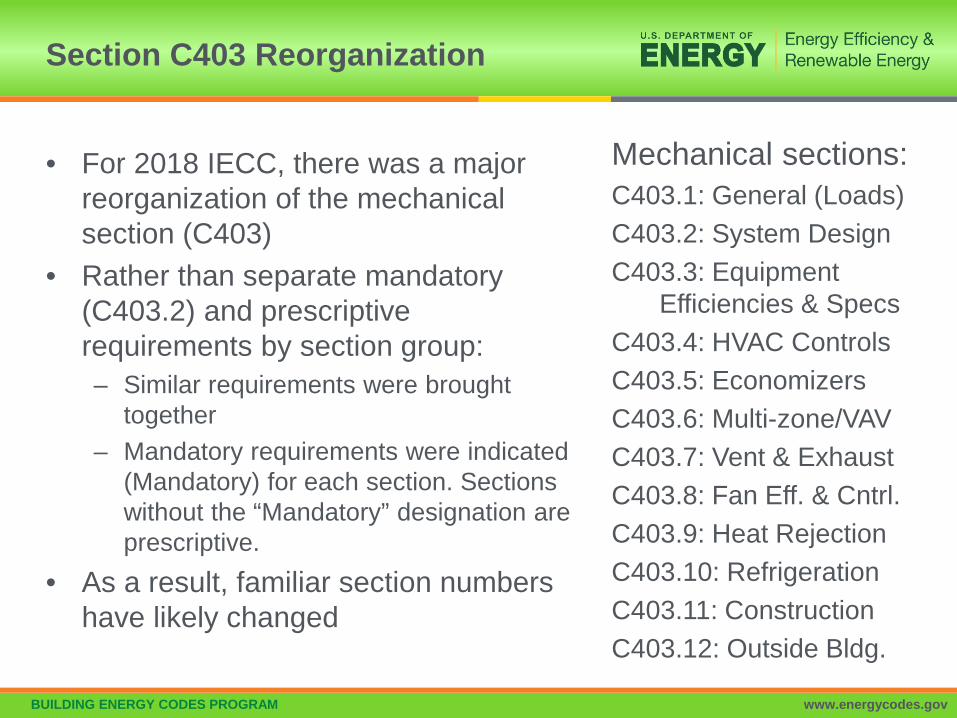
Mechanical sections:C403.1: General (Loads)C403.2: System DesignC403.3: Equipment
Efficiencies & SpecsC403.4: HVAC ControlsC403.5: EconomizersC403.6: Multi-zone/VAVC403.7: Vent & ExhaustC403.8: Fan Eff. & Cntrl.C403.9: Heat RejectionC403.10: RefrigerationC403.11: ConstructionC403.12: Outside Bldg.
• For 2018 IECC, there was a major reorganization of the mechanical section (C403)
• Rather than separate mandatory (C403.2) and prescriptive requirements by section group:– Similar requirements were brought
together– Mandatory requirements were indicated
(Mandatory) for each section. Sections without the “Mandatory” designation are prescriptive.
• As a result, familiar section numbers have likely changed

BUILDING ENERGY CODES PROGRAM www.energycodes.gov
Mandatory Provisions Now Spread through many Sections
Provisions Applicable to ALL Mechanical Systems
Duct and Plenum Insulation and Sealing
Piping Insulation HVAC System Commissioning
and Completion Air System Design and Control Heating Outside a Building Refrigeration Equipment
Performance Walk-in Coolers and Freezers,
Refrigerated Warehouse Coolers and Freezers
Site-built walk-in Coolers and Walk-in Freezers
HVAC Load Calculations Equipment and System Sizing HVAC Equipment Performance
Requirements HVAC System Controls Guestroom HVAC Controls Hot Water Boiler Outdoor
Temp. Set-back Control Ventilation & Vent. Control Energy Recovery Ventilation
Systems Kitchen Exhaust Systems

BUILDING ENERGY CODES PROGRAM www.energycodes.gov
Heating and cooling load sizing calculations required
HVAC Load Calculations Section C403.1.1 (Mandatory)
ASHRAE/ACCA Standard 183 OR Other approved computation procedures – defined in
Chapter 3• Interior design conditions
– Specified by Section C302 of the IECC• ≤ 72oF for heating load• ≥ 75oF for cooling load
Loads reduced from energy recovery systems utilized in the HVAC system shall be accounted for in accordance with the ASHRAE HVAC Systems and Equipment Handbook

BUILDING ENERGY CODES PROGRAM www.energycodes.gov
Divided into isolation areas:• HVAC systems serving zones > 25,000 ft2 in floor area OR • Span > one floor and are designed to operate or be occupied
nonsimultaneouslyIsolation areas:• Isolation devices and controls configured to automatically
shut off the supply of conditioned air and outdoor air to and exhaust air from the isolation area
• Controlled independently by a device meeting C403.4.2.2• Central systems and plants provided with controls and
devices that will allow system and equipment operation for any length of time while serving the smallest isolation area served by system or plant
Zone Isolation (Mandatory)Section C403.2.1

BUILDING ENERGY CODES PROGRAM www.energycodes.gov
Exceptions:• Exhaust air and outdoor air connections to isolation
areas where the fan system to which they connect is < 5,000 cfm
• Exhaust airflow from a single isolation area of < 10% of the design airflow of the exhaust system to which it connects
• Isolation areas intended to operate continuously or intended to be inoperative only when all other isolation areas in a zone are inoperative
Zone Isolation (Mandatory) – Cont’dSection C403.2.1

BUILDING ENERGY CODES PROGRAM www.energycodes.gov
• Natural and mechanical ventilation to be provided in accordance with Chapter 4 of the IMC– If mechanical – system to provide the capability to reduce
outdoor air supply to minimum required by IMC Chapter 4
Ventilation (Mandatory)Section C403.2.2

BUILDING ENERGY CODES PROGRAM www.energycodes.gov
Equipment and System Sizing (Mandatory)Section C403.3.1
Output capacity of heating and cooling equipment only SHALL NOT be greater than calculated loads Select the system which serves the greater load,
heating or cooling– Exceptions:
• Standby Equipment with Required Controls• Multiple Units with Combined Capacities Exceeding Loads
– Sequencing Controls Required

BUILDING ENERGY CODES PROGRAM www.energycodes.gov
Applies to all equipment used in heating and cooling of buildings
Where components from different manufacturers are used• calculations and supporting data demonstrating combined efficiency meets
requirements
Must comply with all listed efficiencies
HVAC Equipment Performance (Mandatory)Section C403.3.2

BUILDING ENERGY CODES PROGRAM www.energycodes.gov
Table C403.3.2(2) Efficiency Requirements (Mandatory)
EQUIPMENT TYPE SIZE CATEGORY HEATING SECTION TYPE
SUBCATEGORY OR RATING CONDITION
MINIMUM EFFICIENCY TEST PROCEDURE
Air cooled (cooling mode) < 65,000 Btu/h All
Split system 14.0 SEER
AHRI 210/240
Single packaged 14.0 SEER
Through-the-wall air cooled ≤ 30,000 Btu/h All
Split system 12.0 SEER
Single packaged 12.0 SEER
Single-duct high-velocity air cooled
< 65,000 Btu/h All Split system11.0 SEER
(partial table; similar to other efficiency tables not shown)

BUILDING ENERGY CODES PROGRAM www.energycodes.gov
• Equipment not designed for operation at AHRI Standard 550/590 test conditions of 44°F leaving chilled-water temperature and 2.4 gpm/ton evaporator fluid flow and 85°F entering condenser water temperature with 3 gpm/ton condenser water flow– To have maximum full-load kW/ton and NPLV ratings adjusted
using Equations 4-6 and 4-7
• The FLadj and PLVadj values are only applicable for centrifugal chillers meeting all of these full-load design ranges– Evaporator leaving temperature ≥ 36°F– Condenser leaving temperature ≤ 115°F– 20°F < LIFT < 80°F
Water-Cooled Centrifugal Chilling PackagesSection C403.3.2.1 (Mandatory)

BUILDING ENERGY CODES PROGRAM www.energycodes.gov
• Equipment with a leaving fluid temperature > 32°F and water-cooled positive displacement chilling packages with a condenser leaving fluid temperature < 115°F to meet Table C403.3.2(7) – when tested or certified with water at standard rating conditions,
in accordance with the referenced test procedure
Positive Displacement (Air- and Water-Cooled Chilling Packages)Section C403.3.2.2

BUILDING ENERGY CODES PROGRAM www.energycodes.gov
Hot Gas Bypass Section C403.3.3
Cooling systems can’t use unless system designed with multiple steps of unloading OR Continuous capacity modulation
Capacity limited per Table C403.3.3 as limited by Section C403.5.1
Rated CapacityMaximum Hot Gas Bypass
Capacity (% of total capacity)
≤ 240,000 Btu/h 50%
> 240,000 Btu/h 25%

BUILDING ENERGY CODES PROGRAM www.energycodes.gov
Boiler systems with design input ≥ 1,000,000 Btu/h to comply with turndown ratio specified in Table C403.3.4
System turndown requirement must be met through the use of
– multiple single input boilers OR– > 1 modulating boilers OR– combination of single input and modulating boilers
Boiler TurndownSection C403.3.4

BUILDING ENERGY CODES PROGRAM www.energycodes.gov
Thermostatic Controls (Mandatory) Section C403.4.1
Control required for each system if zoned for each zone
Exceptions: Independent perimeter systems that are designed to offset only building envelope heat losses or gains or both serving one or more perimeter zones also served by an interior system provided:
1. The perimeter system includes at least one thermostatic control zone for each building exposure having exterior walls facing only one orientation (within +/- 45 degrees) (0.8 rad) for more than 50 contiguous feet (15.2 m); and
2. The perimeter system heating and cooling supply is controlled by a thermostat(s) located within the zone(s) served by the system.

BUILDING ENERGY CODES PROGRAM www.energycodes.gov
Heat pump systems Heat pump thermostat required
when supplying electric resistance heating
Control must prevent supplemental heat demand when heat pump can meet the heating load.
• Except during defrost Can be met by outside air
temperature lockout set to • lock out resistance heat when the
heat pump can meet load• Typically around 35°F
Heat Pump Supplementary Heat (Mandatory) Section C403.4.1.1

BUILDING ENERGY CODES PROGRAM www.energycodes.gov
Thermostats must have at least a 5°F deadband between operation of heating and cooling
Exception:• Thermostats requiring manual change over between heating and
cooling• Occupancies or applications requiring precision in indoor
temperature control as approved by code official
Deadband (Mandatory) Section C403.4.1.2
BUILDING ENERGY CODES PROGRAM www.energycodes.gov
• Where separate thermostatic control devices for heating and cooling in a zone:– Limit switch– Mechanical stop OR– Direct digital control system with software programming shall be
configured to prevent heating set point from exceeding cooling set point to maintain deadband
Set Point Overlap Restriction (Mandatory) Section C403.4.1.3
BUILDING ENERGY CODES PROGRAM www.energycodes.gov
• Heating system for heated vestibules and air curtains with integral heating– Controls configured to shut off heat when outdoor air
temperature is > 45°F
• Heating and cooling systems controlled by thermostat in vestibule configured to limit heating to < 60°F and cooling to >85°F
Exception: control of heating or cooling provided by • site-recovered energy or • transfer air that would otherwise be exhausted
Heated or Cooled Vestibules (Mandatory) Section C403.4.1.4

BUILDING ENERGY CODES PROGRAM www.energycodes.gov
• Hot water boilers that supply heat to the building through one or two-pipe heating systems to have an outdoor setback control that lowers the boiler water temperature based on the outdoor temperature
Hot Water Boiler Outdoor Temp. Set-back Control (Mandatory)Section C403.4.1.5
BUILDING ENERGY CODES PROGRAM www.energycodes.gov
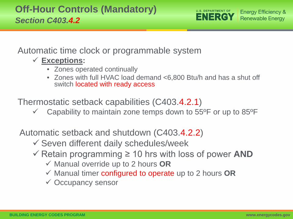
Automatic time clock or programmable system Exceptions:
• Zones operated continually• Zones with full HVAC load demand <6,800 Btu/h and has a shut off
switch located with ready access
Thermostatic setback capabilities (C403.4.2.1) Capability to maintain zone temps down to 55ºF or up to 85ºF
Automatic setback and shutdown (C403.4.2.2)Seven different daily schedules/weekRetain programming ≥ 10 hrs with loss of power AND Manual override up to 2 hours OR Manual timer configured to operate up to 2 hours OR Occupancy sensor
Off-Hour Controls (Mandatory) Section C403.4.2

BUILDING ENERGY CODES PROGRAM www.energycodes.gov
Automatic start controls for each HVAC system
Configured to automatically adjust daily start time to bring each space to desired occupied temperature immediately prior to scheduled occupancy
Automatic Start Capabilities (Mandatory) Section C403.4.2.3

BUILDING ENERGY CODES PROGRAM www.energycodes.gov
Limit reheat/recool of fluids Multiple boiler heating plants must include automatic
controls configured to sequence operation of the boilers Single boilers > 500,000 Btu/h input design capacity must
include multi-staged or modulating burner
Hydronic System ControlsSection C403.4.3

BUILDING ENERGY CODES PROGRAM www.energycodes.gov
3-Pipe System – not allowed (C403.4.3.1) Can’t use a common return
2-Pipe Changeover System (C403.4.3.2) Dead band between changeover ≥ 15ºF outside temperature
Hydronic Systems Section C403.4.3
Diagram Courtesy of Ken Baker

BUILDING ENERGY CODES PROGRAM www.energycodes.gov
Temperature dead band configured to at least 20ºF (C403.4.2.3.1)
Exception:• Where system loop temp optimization controller is installed and can
determine the most efficient operating temp based on real time conditions of demand and capacity
Hydronic Water Loop Heat Pump Systems Section C403.4.3.1
Diagram Courtesy of Ken Baker
Example:Heat rejection off below 75ºF loop temperature.Boiler off above 55ºF loop temperature
75ºF - 55ºF = 20ºF dead band

BUILDING ENERGY CODES PROGRAM www.energycodes.gov
Heat rejection equipment in Climate Zones 3 - 8 Closed-circuit cooling tower used directly in heat pump loop
• Install either automatic valve to bypass flow of water around tower, except for minimal freeze protection flow OR lower leakage positive closure dampers to be provided
Open-circuit tower used directly in heat pump loop• Install automatic valve to bypass all heat pump water flow around
tower Open- or closed-circuit tower used in conjunction with separate
heat exchanger to isolate cooling tower from heat pump loop• Heat loss controlled by shutting down the circulation pump on cooling
tower loop
Exception: Where it can be demonstrated that a heat pump system will be required to reject heat throughout the year
Note: requirement allowing only the heat exchanger option in climate zones 5-8 has been removed; all three options can be used in 3-8 now.
Hydronic Water Loop Heat Pump Systems Section C403.4.3.3.2
BUILDING ENERGY CODES PROGRAM www.energycodes.gov
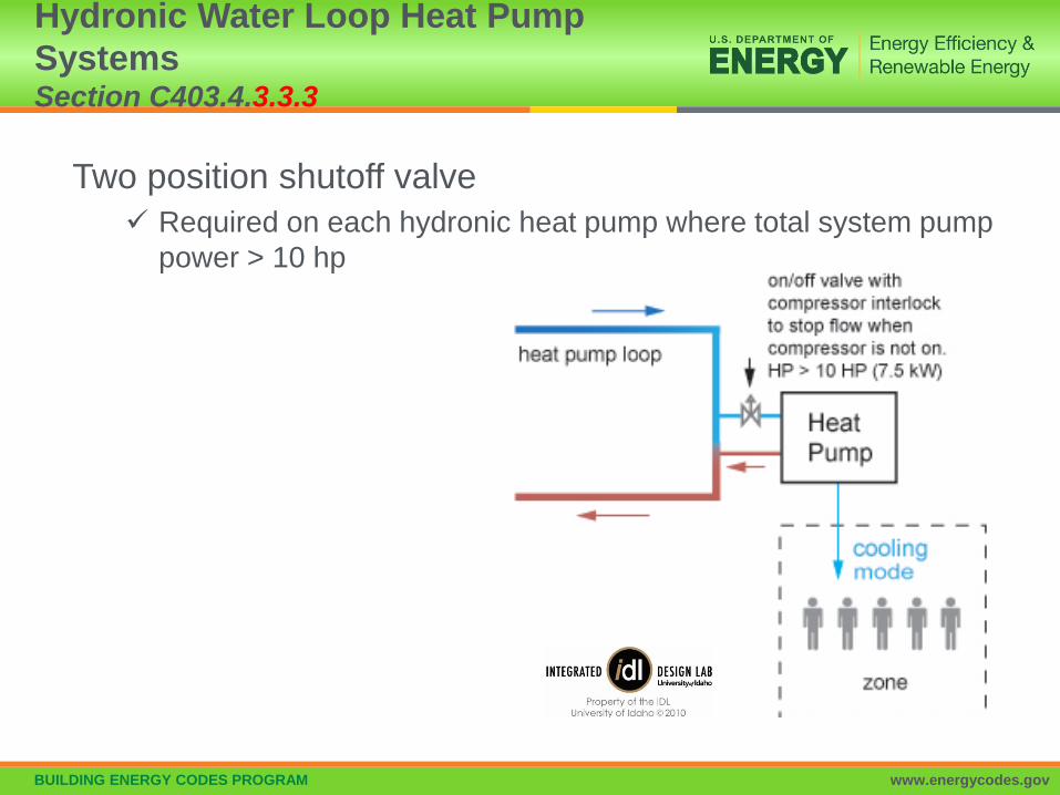
Two position shutoff valve Required on each hydronic heat pump where total system pump
power > 10 hp
Hydronic Water Loop Heat Pump Systems Section C403.4.3.3.3

BUILDING ENERGY CODES PROGRAM www.energycodes.gov
System ≥ 300,000 Btu/h heating or cooling must include Temperature reset and variable flow
• Configured automatic resets for supply water temperature by at least 25% of design supply-to-return temperature differences and
• Automatic vary fluid flow if a combined motor capacity ≥ 2 hp with ≥ 3 control valves or other devices:
Must reduce system design flow rate by > 50% by designed valves or pumps that modulate flow:– Modulating valves or VSD on pumps,– Valves that step open and close OR– Sequencing pumps or valves turn on and of as function of load
Hydronic System Part Load Control Section C403.4.4

BUILDING ENERGY CODES PROGRAM www.energycodes.gov
• Automatic vary pump flow on heating-water systems, chilled-water systems and heat rejection loops serving cooled unitary air conditioners
– Where pumps operate continuously or based on a time schedule, pumps with nominal output hp of ≥ 2hp to have a variable speed drive
– Where pumps have automatic direct digital control configured to operate pumps only when zone heating or cooling is required, a variable speed drive to be provided for pumps with motors having the same or greater nominal output power per Table C403.4.4 based on climate zone and system served
• Where a variable speed drive is required per above bullet, pump motor power input to be not more than 30% of design wattage at 50% of design water flow. Pump flow rate to be controlled to maintain one control valve nearly wide open Or to satisfy the minimum differential pressure.
Hydronic System Part Load Control Section C403.4.4 – Cont’d

BUILDING ENERGY CODES PROGRAM www.energycodes.gov
Exceptions:• Supply-water temp. reset for chilled-water
systems supplied by off-site district chilled water or chilled water from ice storage systems
• Variable pump flow not required on• dedicated coil circulation pumps for freeze protection• dedicated equipment circulation pumps where
configured in primary/secondary design to provide the minimum flow requirements of the equipment manufacturer for proper operation of equipment
• Variable speed drives not required on heating water pumps where more than 50% of annual heat is generated by electric boiler
Hydronic System Part Load Control Section C403.4.4

BUILDING ENERGY CODES PROGRAM www.energycodes.gov
Multiple chiller chilled water plants
Capable and configured to reduce flow through the chiller automatically when chiller is shut down
Chillers piped in series considered one chiller
Multiple boiler plants Capable and configured to
reduce flow through the boiler system automatically when boiler is shut down
Pump Isolation Section C403.4.5
What to look for:Separate pumps for each boiler or chiller with check valves, ORA variable flow pump with isolation valves for each boiler or chiller

BUILDING ENERGY CODES PROGRAM www.energycodes.gov
EconomizersSection C403.5
CLIMATE ZONES ECONOMIZER REQUIREMENT
1A No economizer requirement2A, 2B, 3A, 3B, 3C, 4A, 4B, 4C, 5A, 5B, 5C, 6A, 6B, 7, 8
Economizers on individual DX cooling units ≥ 54,000 Btu/ha
Except for climate zone 1BEconomizer (usually central water economizer) on any chilled water cooling unit if total cooling meets table C403.3 limits
Total supply capacity of all fan-cooling units not provided with economizers shall not exceed 20% of the total supply capacity of all fan-cooling units in the building or 1,500,000 Btu/h, whichever is greater, unless otherwise excepted

BUILDING ENERGY CODES PROGRAM www.energycodes.gov
Climate Zones(Cooling)
Total Chilled-Water System Capacity < Capacity of Cooling Units with Air Economizers
Local Water-cooled Chilled-water Systems
Air-cooled Chilled-water Systems or District Chilled-water Systems
1A No economizer requirement No economizer requirement
1B, 2A, 2B 960,000 Btu/h 1,250,000 Btu/h
3A, 3B, 3C, 4A, 4B, 4C
720,000 Btu/h 940,000 Btu/h
5A, 5B, 5C, 6A, 6B, 7, 8
1,320,000 Btu/h 1,720,000 Btu/h
Economizers – Table C403.5(1)Section C403.5
Example: Hotel with guest room chilled water fan coil units totaling 1,500 MBH of cooling capacity in climate zone 5A• Central water economizer or individual fan coil air
economizers required if a water-cooled chiller• No economizer requirement if all air-cooled chillers or district
chilled water source outside of building

BUILDING ENERGY CODES PROGRAM www.energycodes.gov
Economizer ExceptionsSection C403.5
Exceptions: (economizers not required)
Individual fan systems not served by chilled water in Climate Zones 1A and 1B
Where > 25% of air designed to be supplied by the system is to spaces that are designed to be humidified> 35°F dew-point temperature to satisfy process needs
Systems expected to operate < 20 hours/week Systems serving supermarket areas with open
refrigerated casework systems Where cooling efficiency meets of exceeds efficiency
requirements in Table C403.5(2) Systems that include a heat recovery system in
accordance with Section C403.9.5
BUILDING ENERGY CODES PROGRAM www.energycodes.gov
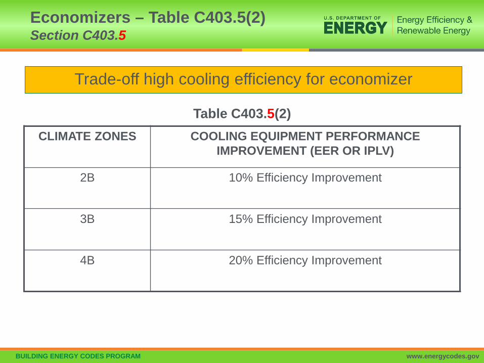
CLIMATE ZONES COOLING EQUIPMENT PERFORMANCE IMPROVEMENT (EER OR IPLV)
2B 10% Efficiency Improvement
3B 15% Efficiency Improvement
4B 20% Efficiency Improvement
Trade-off high cooling efficiency for economizer
Table C403.5(2)
Economizers – Table C403.5(2)Section C403.5

BUILDING ENERGY CODES PROGRAM www.energycodes.gov
• Systems to be integrated with the mechanical cooling system and be configured to provide partial cooling even where additional mechanical cooling is required to provide the remainder of the cooling load
• Controls shall not be capable of creating a false load in the mechanical cooling systems by limiting or disabling the economizer or any other means, such as hot gas bypass, except at the lowest stage of mechanical cooling
Integrated Economizer ControlSection C403.5.1

BUILDING ENERGY CODES PROGRAM www.energycodes.gov
Units that include an air economizer to comply with the following:• Unit controls are configured so the mechanical cooling
capacity control interlocked with the air economizer controls such that the outdoor air damper is at the 100% open position when mechanical cooling is on and the outdoor air damper does not begin to close to prevent coil freezing due to minimum compressor run time until the leaving air temp. < 45°F
• Direct expansion (DX) units that control >75,000 Btu/h of rated capacity of the capacity of the mechanical cooling directly based on occupied space temp. shall have not fewer than two stages of mechanical cooling capacity
• Other DX units including those that control space temp. by modulating the airflow to the space be in accordance with Table C403.5.1
Integrated Economizer ControlSection C403.5.1 – Cont’d

BUILDING ENERGY CODES PROGRAM www.energycodes.gov
HVAC system design and economizer controls shall be such that economizer operation does not increase building heating energy use during normal operations
Exception: Economizers on variable air volume (VAV) systems that cause zone level heating to increase due to a reduction in supply air temperature
Heating System ImpactSection C403.5.2

BUILDING ENERGY CODES PROGRAM www.energycodes.gov
Configured to modulate outdoor air and return air dampers to provide up to 100% of design supply air quantity as outdoor air for cooling
Air Economizers – Design CapacitySection C403.5.3.1
BUILDING ENERGY CODES PROGRAM www.energycodes.gov
Economizer dampers to be configured to sequence with mechanical cooling equipment and not be controlled by only mixed air temperature
Exception: Can use mixed air temperature limit control for systems
controlled from space temperatureExample: single-zone systems
Air Economizers – Control SignalSection C403.5.3.2

BUILDING ENERGY CODES PROGRAM www.energycodes.gov
Air Economizers – High-Limit ShutoffSection C403.5.3.3
Air economizers to be configured to automatically reduce outdoor air intake to design minimum outdoor air quantity when outdoor air intake will no longer reduce cooling energy usage
High-limit shutoff control types to be chosen from Table C403.5.3.3 for specific climates
Specifications for high-limit shutoff control type settings per Table C403.5.3.3

BUILDING ENERGY CODES PROGRAM www.energycodes.gov
Air Economizers – Relief of Excess Outdoor AirSection C403.5.3.4
Systems to be capable of relieving excess outdoor air during air economizer operation to prevent over-pressurizing the building
Relief air outlet to be located to avoid recirculation into the building

BUILDING ENERGY CODES PROGRAM www.energycodes.gov
Return, exhaust/relief and outdoor air dampers used in economizers shall comply with Section C403.7.7 (Shut Off Dampers)
Air Economizers – DampersSection C403.5.3.5
BUILDING ENERGY CODES PROGRAM www.energycodes.gov
Configured to cool supply air by indirect evaporation and provide up to 100% of expected system cooling load at outdoor air temperatures < 50ºF dry bulb/45ºF wet bulb
Exceptions:• Systems primarily serving computer rooms in which 100% of
expected system cooling load at 40ºF dry bulb/35ºF wet bulb is met with evaporative water economizers
• Systems primarily serving computer rooms with dry cooler water economizers which satisfy 100% of the expected system cooling load at 35ºF dry bulb
• Systems where dehumidification requirements cannot be met using outdoor air temps of 50ºF dry bulb/45ºF web bulb and where 100% of expected system cooling load at 45ºF dry bulb/40ºF wet bulb is met with evaporative water economizers
Water-side Economizers – Design CapacitySection C403.5.4.1

BUILDING ENERGY CODES PROGRAM www.energycodes.gov
Precooling coil and water-to-water heat exchangers used as part of a water economizer system to have either a:• water side pressure drop < 15 feet of water OR• secondary loop created so that the coil or heat exchanger pressure
drop is not seen by the circulating pumps when the system is in normal cooling (non-economizer) mode
Water-side Economizers – Maximum Pressure DropSection C403.5.4.2

BUILDING ENERGY CODES PROGRAM www.energycodes.gov
• Air cooled unitary direct-expansion units (listed in Tables C403.3.2(1-3) and variable refrigerant flow (VRF) units that are equipped with an economizer per C403.5 to C403.5.4 to include a fault detection and diagnostics (FDD) system complying with the following:– Temperature sensors permanently installed to monitor system
operation• Outside air• Supply air• Return air
– Temperature sensors have an accuracy of +2°F over the range of 40°F - 80°F
– Refrigerant pressure sensors, where used, have an accuracy of +3% of full scale
Economizer Fault Detection and Diagnostics (Mandatory)Section C403.5.5

BUILDING ENERGY CODES PROGRAM www.energycodes.gov
• Unit controller configured to provide system status by indicated the following:– Free cooling available– Economizer enabled– Compressor enabled– Heating enabled– Mixed air low limit cycle active– Current value of each sensor
• Unit controller capable of manually initiating each operating mode so that the operation of compressors, economizers, fans and heating system can be independently tested and verified
Economizer Fault Detection and Diagnostics (Mandatory)Section C403.5.5 – Cont’d

BUILDING ENERGY CODES PROGRAM www.energycodes.gov
• Unit configured to report faults to a fault management application accessible by day-to-day operating or service personnel, or annunciated locally on zone thermostats
• The FDD system configured to detect the following faults:– Air temperature sensor failure/fault– Not economizing when the unit should be economizing– Economizing when the unit should not be economizing– Damper not modulating– Excess outdoor air
Economizer Fault Detection and Diagnostics (Mandatory)Section C403.5.5 – Cont’d

BUILDING ENERGY CODES PROGRAM www.energycodes.gov
• Supply air systems serving multiple-zones shall be VAV systems with zone controls to reduce reheated air to one of the following:– 20% of zone peak supply for DDC (30% others)– DDC with 20% air in deadband, first stage heating at 20%, second
stage heating up to 50% zone airflow– Airflow required to meet IMC ventilation requirements– A higher rate shown to use less energy through system OA
reduction– Airflow required for accreditation standards
• Exceptions:– Zones or supply air systems where not less than 75% of the energy for
reheating or for providing warm air in mixing systems is provided from a site-recovered energy source.
– Systems that prevent reheating, recooling, mixing or simultaneous supply of air that has been previously cooled (mechanically or economizer) and heated air.
VAV & Multiple-zone SystemsSection C403.6.1

BUILDING ENERGY CODES PROGRAM www.energycodes.gov
Single duct VAV systems to use terminal devices capable of and configured to reduce the supply of primary supply air before reheating or recooling takes place
Single Duct VAV Systems, Terminal Devices Section C403.6.2

BUILDING ENERGY CODES PROGRAM www.energycodes.gov
Systems with one warm air duct and one cool air duct to use terminal devices configured to reduce flow from one duct to a minimum before mixing of air from the other duct takes place
Dual Duct and Mixing VAV Systems, Terminal Devices Section C403.6.3
BUILDING ENERGY CODES PROGRAM www.energycodes.gov
Individual dual duct or mixing reheating and cooling systems with a single fan and with total capacities > 90,000 Btu/h (7.5 tons) should not have economizers
Single Fan Dual Duct and Mixing VAV Systems, Economizers Section C403.6.4

BUILDING ENERGY CODES PROGRAM www.energycodes.gov
Multiple zone HVAC systems to have controls to automatically reset supply-air temperature in response to building loads or outdoor air temperature
Controls to be configured to reset supply air temperature at least 25% of difference between design supply-air temperature and design room air temperature
Exceptions: Systems that prevent reheating, recooling or mixing of heated
and cooled supply air 75% of energy for reheating is from site-recovered or site solar
energy sources Zones with peak supply air quantities of ≤ 300 cfm
Supply-Air Temperature Reset Controls Section C403.6.5

BUILDING ENERGY CODES PROGRAM www.energycodes.gov
• Multiple-zone VAV systems with direct digital control of individual zone boxes reporting to central control panel– Automatic controls configured to reduce outdoor air intake flow
below design rates in response to changes in system ventilation efficiency (Ev) as defined by IMC
• Exceptions:– VAV systems with zonal transfer fans that recirculate air from other
zones without directly mixing it with outdoor air, dual-duct dual-fan VAV systems, and VAV systems with fan-powered terminal units
– Systems where total design exhaust airflow is > 70% of total design outdoor air intake flow requirements
Multiple-zone VAV System Ventilation Optimization ControlSection C403.6.6

BUILDING ENERGY CODES PROGRAM www.energycodes.gov
• Parallel fan-powered VAV zone terminal units shall be configured to operate as follows:– Turn off the terminal fan except when space heating is required
or where required for ventilation.– Turn on the terminal fan as the first stage of heating before the
heating coil is activated.– During heating for warmup or setback temperature control,
either:• Operate the terminal fan and heating coil without primary air.• Reverse the terminal damper logic and provide heating from the
central air handler by primary air.
Parallel fan-powered VAV zone controlSection C403.6.7

BUILDING ENERGY CODES PROGRAM www.energycodes.gov
• Systems with direct digital control of individual reporting to the central control panel– Static pressure set point to be reset based on the zone requiring
the most pressure (i.e., the set point is reset lower until one zone damper is nearly wide open)
– Direct digital controls capable of monitoring zone damper positions or have an alternative method of indication the need for static pressure configured to provide all of the following:
• Automatically detecting any zone that excessively drives the reset logic
• Generating an alarm to the system operational location• Allowing an operator to readily remove > 1 zones from the reset
algorithm
Setpoints for Direct Digital ControlSection C403.6.8

BUILDING ENERGY CODES PROGRAM www.energycodes.gov
Sensors used to control VAV fans– Placed so that the controller setpoint is ≤ 1.2 inches w.c.
Sensors installed downstream of major duct splits– At least one sensor to be located on each major branch so that
static pressure can be maintained in each branch
Static Pressure Sensor LocationSection C403.6.9

BUILDING ENERGY CODES PROGRAM www.energycodes.gov
DCV must be provided for each zone with spaces > 500 ft² and the average occupant load ≥ 25 people/1000 ft² of floor area (per IMC table 403.3.1.1) where the HVAC system has:
An air-side economizer, or Automatic modulating control of the outdoor air damper, or A design outdoor airflow > 3,000 cfm
Demand Controlled Ventilation (Mandatory)Section C403.7.1
Demand control ventilation (DCV): a ventilation system capability that provides for the automatic reduction of outdoor air intake below design
rates when the actual occupancy of spaces served by the system is less than design occupancy.

BUILDING ENERGY CODES PROGRAM www.energycodes.gov
Exceptions: Systems with energy recovery per C403.7.4 Multiple zone systems without direct digital control of
single zones communicating with central control panel Systems with design outdoor airflow < 1,200 cfm Spaces where supply airflow rate minus any makeup or
outgoing transfer air requirement < 1,200 cfm Ventilation provided only for process loads
Demand Controlled Ventilation (Mandatory) Section C403.7.1 – Cont’d
BUILDING ENERGY CODES PROGRAM www.energycodes.gov
• Garages for storing or handling automobiles operating under their own power shall employ contamination-sensing devices and automatic controls configured to stage fans or modulate fan average airflow rates to < 50% of design capacity, or intermittently operate fans < 20% of occupied time or as required to maintain acceptable contaminant levels in accordance with IMC provisions
• Failure of these devices shall cause the exhaust fans to operate continuously at design airflow
Exceptions:– Garages with total exhaust capacity < 22,500 cfm with ventilation
systems that do not utilize heating or mechanical cooling– Garages that have garage area to ventilation system motor
nameplate power ratio >1,125 cfm/hp and do not utilize heating or mechanical cooling
Enclosed Parking Garage Ventilation Controls (Mandatory)Section C403.7.2
BUILDING ENERGY CODES PROGRAM www.energycodes.gov
• Units providing ventilation air to multiple zones and operating in conjunction with zone heating and cooling systems to not use heating or heat recovery to warm supply air to a temperature > 60ºF when representative building loads or outdoor air temperatures indicate majority of zones require cooling.
Things to look for:• Applies to DOAS systems with or without heating or cooling
capability• HRV or ERV systems will require bypass of flat plate exchangers or
speed control of heat wheels• “Neutral air” control is not allowed
Ventilation Air Heating Control (Mandatory)Section C403.7.3

BUILDING ENERGY CODES PROGRAM www.energycodes.gov
Applies to fan systems with supply airflow rates > values in Tables C403.7.4(1-2)Note that prior 0 cfm values in tables have been increased
Exhaust air total recovery efficiency must be ≥ 50%When an air economizer is required
– include a bypass or controls that permit operation of economizer per C403.5
Energy Recovery Ventilation Systems (Mandatory)Section C403.7.4
Energy recovery ventilation (ERV) systems: employ air-to-air heat exchangers to recover energy from exhaust air for the purpose of preheating, precooling,
humidifying or dehumidifying outdoor ventilation air prior to supplying the air to a space, either directly or as part of an HVAC system.

BUILDING ENERGY CODES PROGRAM www.energycodes.gov
Exceptions: Where energy recovery ventilation systems prohibited by the IMC Lab fume hood system with at least one of the following:
– VAV hood exhaust and room supply systems configured to reduce exhaust and makeup air volume to ≤ 50% of design values
– Direct makeup (auxiliary) air supply equal to at least 75% of exhaust rate, heated no warmer than 2ºF below room setpoint, cooled to no cooler than 3ºF above room setpoint, with no humidification added, and no simultaneous heating and cooling use for dehumidification control
Systems serving uncooled spaces and heated to < 60ºF Where > 60% of outdoor heating energy is from site-recovered or site solar
energy Heating energy recovery in Climate Zones 1-2 Cooling energy recovery in Climate Zones 3C, 4C, 5B, 5C, 6B, 7, and 8 Systems requiring dehumidification that employ energy recovery in series
with the cooling coil Where largest source of air exhausted at a single location at building exterior
is < 75% of design outside air flow rate Systems expected to operate < 20 hours/week at outdoor air % covered by
Table C403.7.4(1) Systems exhausting toxic, flammable, paint or corrosive fumes or dust Commercial kitchen hoods used for collecting and removing grease vapors
and smoke
Energy Recovery Ventilation Systems (Mandatory)Section C403.7.4 – Cont’d

BUILDING ENERGY CODES PROGRAM www.energycodes.gov
• Replacement air introduced directly into the exhaust hood cavity shall not be > 10% of the hood exhaust airflow rate
• Conditioned supply air delivered to any space shall not exceed the greater of the following:– Ventilation rate required to meet the space heating or cooling
load– Hood exhaust flow minus the available transfer air from adjacent
space where available transfer air is considered to be that portion of outdoor ventilation air not required to satisfy other exhaust needs, such as restrooms, and not required to maintain pressurization of adjacent spaces
Kitchen Exhaust Systems (Mandatory)Section C403.7.5

BUILDING ENERGY CODES PROGRAM www.energycodes.gov
• Total kitchen hood exhaust flow rate >5,000 cfm, each hood be a factory built commercial exhaust hood listed by nationally recognized testing laboratory in compliance with UL 710
• Each hood shall have a maximum exhaust rate as specified in Table C403.7.5Where a single hood, or hood section, is installed over appliances with different duty ratings, the maximum allowable flow rate for the hood or hood section shall be based on the requirements for the highest appliance duty rating under the hood or hood section
• Exception: where at least 75% of the replacement air is transfer air that would otherwise be exhausted
Kitchen Exhaust Systems (Mandatory)Section C403.7.5 – Cont’d

BUILDING ENERGY CODES PROGRAM www.energycodes.gov
• Each kitchen exhaust hood shall comply with one of the following:– Not < 50% of all replacement air shall be transfer air that would
otherwise be exhausted– Demand ventilation systems on not < 75% of the exhaust air that
are configured to provide not less than 50% reduction in exhaust and replacement air system airflow rates including controls necessary to modulate airflow in response to appliance operation and maintain full capture and containment of smoke, effluent and combustion products during cooking and idle
– Listed energy recovery devices with a sensible heat recovery effectiveness not <40% on not <50% of the total exhaust airflow
Kitchen Exhaust Systems (Mandatory)Section C403.7.5 – Cont’d

BUILDING ENERGY CODES PROGRAM www.energycodes.gov
• In Group R-1 buildings with > 50 guestrooms, each guestroom to be provided with controls complying with C403.7.6.1 and C403.7.6.2.
– For these systems room occupancy sensing can be either:• Occupant sensors, or • Card key controls
– For these systems unrented rooms can be determined either:• With a signal from a networked reservation, or• After 16 hours of continuous vacancy
Automatic Control of HVAC Systems Serving Guestrooms (Mandatory)Section C403.7.6
BUILDING ENERGY CODES PROGRAM www.energycodes.gov
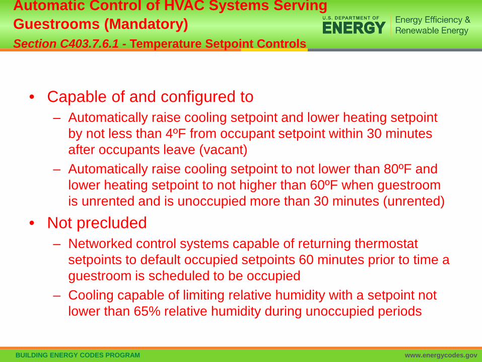
• Capable of and configured to– Automatically raise cooling setpoint and lower heating setpoint
by not less than 4ºF from occupant setpoint within 30 minutes after occupants leave (vacant)
– Automatically raise cooling setpoint to not lower than 80ºF and lower heating setpoint to not higher than 60ºF when guestroom is unrented and is unoccupied more than 30 minutes (unrented)
• Not precluded– Networked control systems capable of returning thermostat
setpoints to default occupied setpoints 60 minutes prior to time a guestroom is scheduled to be occupied
– Cooling capable of limiting relative humidity with a setpoint not lower than 65% relative humidity during unoccupied periods
Automatic Control of HVAC Systems Serving Guestrooms (Mandatory)Section C403.7.6.1 - Temperature Setpoint Controls
BUILDING ENERGY CODES PROGRAM www.energycodes.gov
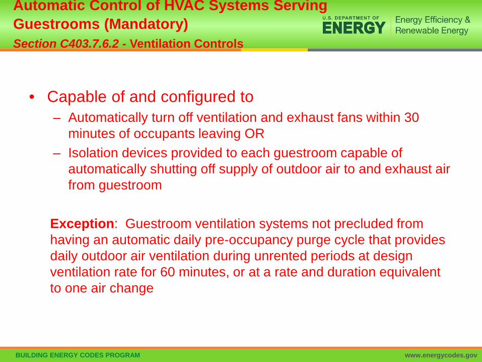
• Capable of and configured to– Automatically turn off ventilation and exhaust fans within 30
minutes of occupants leaving OR– Isolation devices provided to each guestroom capable of
automatically shutting off supply of outdoor air to and exhaust air from guestroom
Exception: Guestroom ventilation systems not precluded from having an automatic daily pre-occupancy purge cycle that provides daily outdoor air ventilation during unrented periods at design ventilation rate for 60 minutes, or at a rate and duration equivalent to one air change
Automatic Control of HVAC Systems Serving Guestrooms (Mandatory)Section C403.7.6.2 - Ventilation Controls

BUILDING ENERGY CODES PROGRAM www.energycodes.gov
• Outdoor air intake and exhaust openings and stairway and shaft vents provided with Class I motorized dampers
• Dampers with air leakage rate < 4 cfm ft2 of damper surface at 1.0 inch water gauge (249 Pa) and labeled and approved in accordance with AMCA 500D
• Outdoor air intake and exhaust dampers with automatic controls configured to close the systems or spaces served when not in use or during unoccupied period warm-up and setback operation • Unless systems served require outdoor or exhaust air per IMC
OR• Dampers are opened to provide intentional economizer cooling
Shutoff Dampers (Mandatory) Section C403.7.7

BUILDING ENERGY CODES PROGRAM www.energycodes.gov
• Stairway and shaft vent dampers installed with automatic controls configured to open up on activation of any fire alarm initiating device of the building’s fire alarm system or the interruption of power to the damper Exceptions non-motorized gravity dampers permitted :
• in buildings < 3 stories• for buildings of any height located in Climate Zones 1-3• outside air intake or exhaust airflows of 300 cfm (0.14m3/s) or less
Shutoff Dampers (Mandatory) Section C403.7.7 – Cont’d

BUILDING ENERGY CODES PROGRAM www.energycodes.gov
• Gravity motorized dampers shall have an air leakage rate:– < 20 cfm/ft2 where > 24 inches in either dimension – 40 cfm/ft2 where < 24 inches in either dimension
• Air leakage rate determined at 1.0 inch water gauge (249 Pa) when tested in accordance with AMCA 500D
• Dampers labeled by an approved agency
Shutoff Dampers (Mandatory) Section C403.7.7 – Cont’d
BUILDING ENERGY CODES PROGRAM www.energycodes.gov
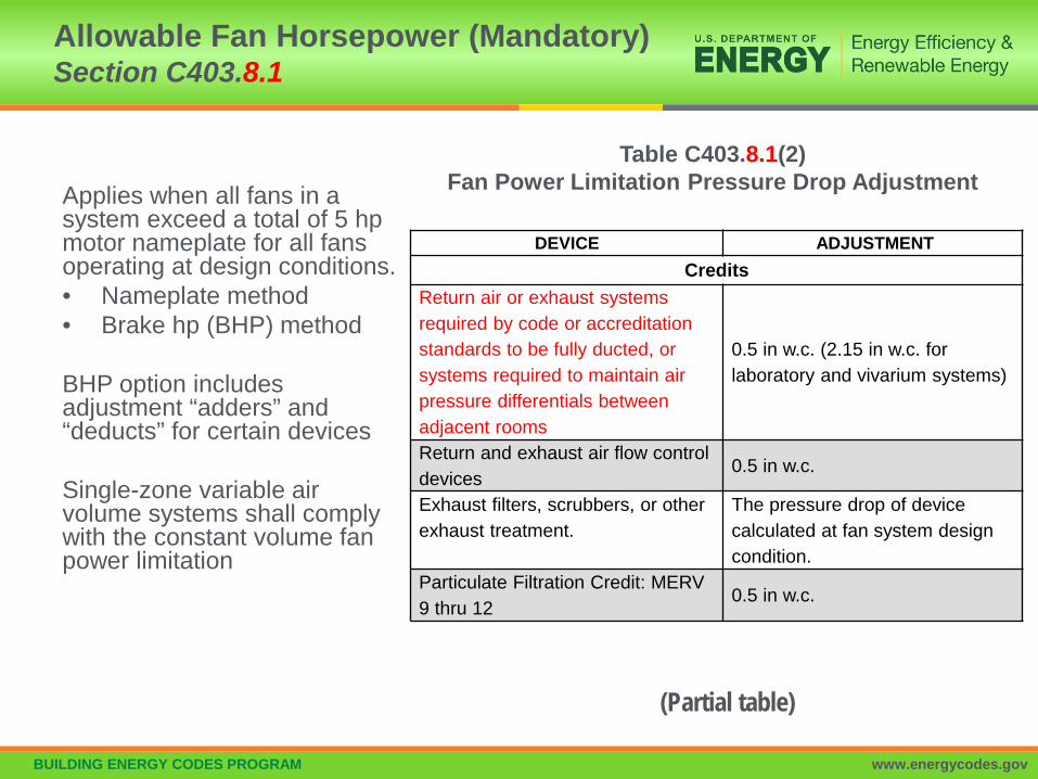
Applies when all fans in a system exceed a total of 5 hpmotor nameplate for all fans operating at design conditions.• Nameplate method• Brake hp (BHP) method
BHP option includes adjustment “adders” and “deducts” for certain devices
Single-zone variable air volume systems shall comply with the constant volume fan power limitation
Allowable Fan Horsepower (Mandatory)Section C403.8.1
DEVICE ADJUSTMENT Credits
Return air or exhaust systems required by code or accreditation standards to be fully ducted, or systems required to maintain air pressure differentials between adjacent rooms
0.5 in w.c. (2.15 in w.c. for laboratory and vivarium systems)
Return and exhaust air flow control devices
0.5 in w.c.
Exhaust filters, scrubbers, or other exhaust treatment.
The pressure drop of device calculated at fan system design condition.
Particulate Filtration Credit: MERV 9 thru 12
0.5 in w.c.
(Partial table)
Table C403.8.1(2)Fan Power Limitation Pressure Drop Adjustment

BUILDING ENERGY CODES PROGRAM www.energycodes.gov
Exceptions: Hospital, vivarium, and laboratory systems using flow control
devices on exhaust and/or return for health and safety or environmental control permitted to use variable fan power limitation
Individual exhaust fans with motor nameplate ≤ 1 hp
Allowable Fan Horsepower (Mandatory)Section C403.8.1 – Cont’d

BUILDING ENERGY CODES PROGRAM www.energycodes.gov
Selected fan motor to be no larger than first available motor size greater than bhp
Fan bhp on design documents
Exceptions Fans < 6 bhp, where first available motor larger than bhp has
nameplate rating within 50% of bhp, next larger nameplate motor size may be selected
Example: 5.2 Bhp; next size of 7.5 is within 1.5 * Bhp (7.8) so may upsize to 10 HP, or next size after 7.5 HP
Fans ≥ 6 bhp, where first available motor larger than bhp has nameplate rating within 30% of bhp, next larger nameplate motor size may be selected
Fans with motor nameplate hp < 1 hp
Motor Nameplate Horsepower (Mandatory)Section C403.8.2
bhp = brake horsepower

BUILDING ENERGY CODES PROGRAM www.energycodes.gov
• Have a fan efficiency grade (FEG) < 67 as determined in accordance with AMCA 205 by an approved independent testing laboratory or labeled by the manufacturer
• Total efficiency at the design point of operation be within 15 percentage points of the max. total efficiency of the fan
• Exceptions:– Fans of < 5 hp
• Individual fans with a motor nameplate horsepower of <5 hp UNLESS
• Multiple fans in a series or parallel that have a combined motor nameplate horsepower < 5hp and are operated as the functional equivalent of a single fan
Fan Efficiency (Mandatory)Section C403.8.3

BUILDING ENERGY CODES PROGRAM www.energycodes.gov
Exceptions (cont’d)• Fans that are part of the equipment covered in Section
C403.3.2• Fans included in an equipment package certified by an
approved agency for air or energy performance• Powered wall/roof ventilators• Fans outside the scope of AMCA 205• Fans that are intended to operate only during emergency
conditions
Fan Efficiency (Mandatory)Section C403.8.3 – Cont’d

BUILDING ENERGY CODES PROGRAM www.energycodes.gov
• Motors for fan ≥ 1/12 hp and < 1 hp shall be electronically commutated motors OR have a minimum motor efficiency of 70% rated in accordance with DOE 10 CFR 431
• Motors must have the means to adjust motor speed for either balancing or remote control
• The use of belt-driven fans with sheave adjustments for airflow balancing instead of a varying motor speed is permitted
Exceptions:– Motors in the airstream within fan coils and terminal units that only
provide heating to the space served– Motors in space-conditioning equipment that comply with Section
C403.3.2 or C403.8.1 through C403.8.3– Motors that comply with Section C405.7
Fractional hp Fan Motors Section C403.8.4

BUILDING ENERGY CODES PROGRAM www.energycodes.gov
Each cooling system listed in Table C403.8.5.1(DX ≥65 MBH capacity & chilled water or evaporative with fan ≥ ¼ hp)to be designed to vary the indoor fan airflow as a function of load and comply with the following:• Direct expansion (DX) and chilled water cooling units that
control capacity of mechanical cooling directly based on space temp to have not fewer than 2 stages of fan control– Low or minimum speed < 66% full speed
• fan to draw < 40% of fan power at full fan speed• Used during period of low cooling load and ventilation-only operation
• Other units including DX cooling and chilled water that control the space temp. by modulating the airflow to the space have modulation fan control (usually a variable speed drive)– Minimum speed < 50% of full speed
• Fan to draw < 30% of fan power at full fan speed– Low or minimum speed used during period of low cooling load and
ventilation-only operation
Fan Airflow ControlSection C403.8.5.1
BUILDING ENERGY CODES PROGRAM www.energycodes.gov
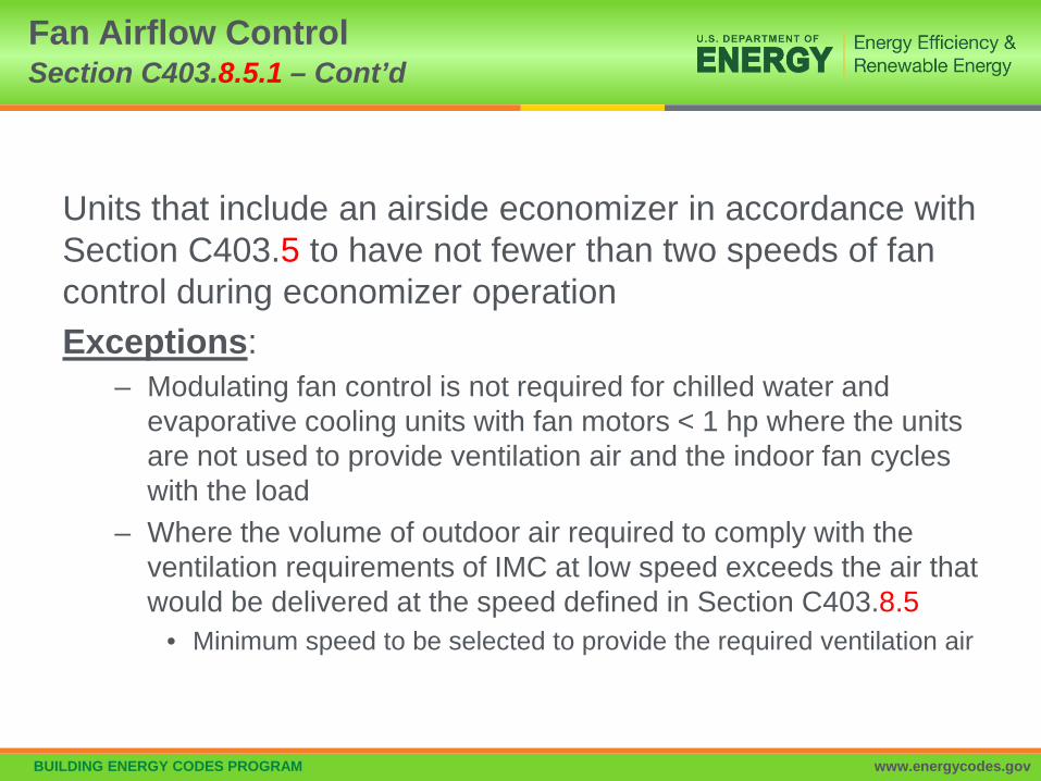
Units that include an airside economizer in accordance with Section C403.5 to have not fewer than two speeds of fan control during economizer operationExceptions:
– Modulating fan control is not required for chilled water and evaporative cooling units with fan motors < 1 hp where the units are not used to provide ventilation air and the indoor fan cycles with the load
– Where the volume of outdoor air required to comply with the ventilation requirements of IMC at low speed exceeds the air that would be delivered at the speed defined in Section C403.8.5
• Minimum speed to be selected to provide the required ventilation air
Fan Airflow ControlSection C403.8.5.1 – Cont’d

BUILDING ENERGY CODES PROGRAM www.energycodes.gov
Each tower fan powered by a motor ≥ 7.5 hp must include variable speed or two speed fanHave controls to automatically change the fan speed to control the
leaving fluid temperature or condensing temperature/pressure of the heat rejection deviceException:
• Heat rejection devices where energy usage is included in the ratings in accordance with Tables C403.3.2(6) and C403.3.2(7)
Heat Rejection Equipment Section C403.9
BUILDING ENERGY CODES PROGRAM www.energycodes.gov
• Air-cooled condensers, dry coolers, open-circuit cooling towers, closes-circuit cooling towers, and evaporative condensers used for comfort cooling applications must comply with Section C403.9
– Exception: heat rejection devices where energy usage is included in the equipment efficiency ratings listed in Tables C403.3.2(6) and C403.3.2(7)
Heat Rejection Equipment Section C403.9 – General
BUILDING ENERGY CODES PROGRAM www.energycodes.gov
Fan motors > 5hp must have• Controls that automatically modulate fan speed to control
the leaving fluid temp. or condensing temp./pressure of the heat rejection device
• Fan motor power input to be not more than 30% of design wattage or 50% of design airflow
Exception:• Condenser fans serving multiple refrigerant or fluid
cooling circuits• Condenser fans serving flooded condensers
Heat Rejection Equipment Section C403.9.1 – Fan Speed Control

BUILDING ENERGY CODES PROGRAM www.energycodes.gov
Multiple-cell heat rejection equipment with variable speed fan drives to be controlled in both manners:• Operate the maximum number of fans allowed that
comply with manufacturer’s requirements for all system components
• So all fans can operate at the same fan speed required for the instantaneous cooling duty, as opposed to staged (on/off) operation
Minimum fan speed must be the minimum allowable speed of the fan drive system in accordance with manufacturer’s recommendations
Heat Rejection Equipment Section C403.9.2 – Multiple-cell

BUILDING ENERGY CODES PROGRAM www.energycodes.gov
Centrifugal fan open-circuit cooling towers with combined rated capacity > 1,100 gpm at 95ºF condenser water return, 85ºF condenser water supply, 75ºF outdoor air wet-bulb temperature must meet the energy efficiency requirement for axial fan open-circuit cooling towers listed in Table C403.3.2(8)
Exception:Centrifugal open-circuit cooling towers that are designed with inlet or discharge ducts or require external sound attenuation
Heat Rejection Equipment Section C403.9.3 – Limitation on Centrifugal Fan Open-circuit Cooling Towers

BUILDING ENERGY CODES PROGRAM www.energycodes.gov
Open-circuit cooling towers used on water-cooled chiller system that are configured with multiple or variable-speed condenser water pumps • Designed that all open circuit cooling tower cells can be
run in parallel with the larger of • the flow that is produced by the smallest pump at its minimum
expected flow rate OR• 50% of the design flow for the cell
Heat Rejection Equipment Section C403.9.4 – Tower Flow Turndown

BUILDING ENERGY CODES PROGRAM www.energycodes.gov
CW InHW In
Storage Tank
Condenser
Evaporator
Heat Recovery Heat Pump
Cooling TowerWater Loop
To Chiller Condenser or Water-Loop Heat Pump
System
CW InHW In
Storage Tank
Condenser
Evaporator
Heat Recovery Heat Pump
Cooling TowerWater Loop
To Chiller Condenser or Water-Loop Heat Pump
System
Condenser heat recovery required for heating/reheating of SWH provided:
Facility operates 24 hours/day Total installed heat capacity of the
heat rejection of water-cooled systems >6,000,000 Btu/hr
Design SWH load >1,000,000 Btu/hr
Capacity to provide the smaller of 60% of peak heat rejection load at
design conditions OR Preheating to raise peak SWH to
85ºF
Exceptions: Recovered heat is used for space
heating or when 60% of SWH is heated by renewables or site recovered energy sources
Heat Recovery for Service Hot Water Heating Section C403.9.5

BUILDING ENERGY CODES PROGRAM www.energycodes.gov
Note: the following are generally in line with federal manufacturing requirements.• Equipment have an energy use in kWh/day ≤ the values
of Tables C403.10(1-2) when tested and rated in accordance with AHRI Standard 1200
• Energy use shall be verified through certification under an approved certification program or where a certification program does not exist, the energy use shall be supported by data furnished by the equipment manufacturer
Refrigeration Equipment Performance (Mandatory)Section C403.10
BUILDING ENERGY CODES PROGRAM www.energycodes.gov
• Be equipped with automatic door-closers that firmly close walk-in doors that have been closed to within 1” of full closure– Exception – automatic closers are not required for doors >45” in
width or > 7ft in height
• Doorways have strip doors, curtain, spring hinged doors or other approved method of minimizing infiltration when doors are open
• Walk-in coolers and refrigerated warehouse coolers shall have wall, ceiling, and door insulation of > R-25 and walk-in freezers and refrigerated warehouse freezers > R-32– Exception – glazed portions of doors or structural members
need not be insulated
Walk-in Coolers, Walk-in Freezers, Refrigerated Warehouse Coolers/Freezers (Mandatory) Section C403.10.1

BUILDING ENERGY CODES PROGRAM www.energycodes.gov
• Walk-in freezers contain floor insulation > R-28• Transparent reach-in doors for walk-in freezers and
windows in walk-in freezer doors shall be of triple-pane glass, either filled with inert gas or with heat-reflective treated glass
• Windows and transparent reach-in doors for walk-in coolers, doors shall be of double-pane or triple pane, inert gas-filled, heat-reflective treated glass
• Evaporator fan motors that are < 1hp and < 460 volts use electronically commutated motors, brushless direct-current motors, or 3-phase motors
• Condenser fan motors < 1hp use electronically commutated motors, permanent split capacitor-type motors or 3-phase motors
Walk-in Coolers, Walk-in Freezers, Refrigerated Warehouse Coolers/Freezers (Mandatory)Section C403.10.1 – Cont’d

BUILDING ENERGY CODES PROGRAM www.energycodes.gov
• Antisweat heaters without antisweat heater controls:limit total door rail, glass and frame heater power draw < 7.1W/ft2 of door opening for walk-in freezers and 3.0 W/ft2 of door opening for walk-in coolers
• Where antisweat heater controls are providedreduce the energy use of the antisweat heater as a function of the relative humidity in the air outside the door or of the condensation on the inner glass plane
Walk-in Coolers, Walk-in Freezers, Refrigerated Warehouse Coolers/Freezers (Mandatory) Section C403.10.1 – Cont’d

BUILDING ENERGY CODES PROGRAM www.energycodes.gov
Site assembled or site constructed walk-ins have very similar provisions to pre-manufactured walk-ins covered under C403.10.1 with the following differences (underlined):
• Exception to item 3: insulation is not required for glazed portions of doors or at structural members associated with the walls, ceiling or door frame
• Exception to item 8: Fan motors in walk-in coolers and walk-in freezers combined in a single enclosure greater than 3,000 square feet (279 m2) in floor area are exempt.
• C403.10.2.1 Performance standards (Mandatory). Effective January 1, 2020, walk-in coolers and walk-in freezers shall meet the requirements of Tables C403.10.2.1(1), C403.10.2.1(2) and C403.10.2.1(3).
Walk-in Coolers and Walk-in Freezers (Mandatory)Section C403.10.2

BUILDING ENERGY CODES PROGRAM www.energycodes.gov
Site-assembled or site-constructed refrigerated display cases shall comply with the following:• Lighting and glass doors controlled by one of the following:
– Time switch controls to turn off lights during nonbusiness hours. Timed overrides for display case shall turn the lights on for up to 1 hour and automatically time out to turn the lights off
– Motion sensor controls on each display case section that reduce lighting power by at least 50% within 3 minutes after the area within the sensor range is vacated
• Low-temp. display cases incorporate temp.-based defrost termination control with a time-limit default. The defrost cycle shall terminate first on an upper temp. limit breach and second upon a time limit breach.
• Antisweat heater controls to reduce the energy use of the antisweat heater as a function of the relative humidity in the air outside the door or to the condensation on the inner glass pane
Refrigerated Display Cases (Mandatory)Section C403.10.3

BUILDING ENERGY CODES PROGRAM www.energycodes.gov
• Display cases, walk-in coolers or walk-in freezers served by remote compressors and remote condensers not located in a condensing unit must comply with Sections C403.10.4.1 and C403.10.4.2
• Exception: Systems where the working fluid in the refrigeration cycle goes through both subcritical and supercritical states (transcritical) or that use ammonia refrigerant
Refrigeration SystemsSection C403.10.4

BUILDING ENERGY CODES PROGRAM www.energycodes.gov
Fan-Powered Condensers
• Design saturated condensing temperatures for air-cooled condenser not to exceed– design dry-bulb temp. plus 10ºF for low-temp. refrigeration
systems– Design dry-bulb temp. plus 15ºF for medium temp. refrigeration
systems where saturated condensing temp. for blend refrigerants should be determined using the average of liquid vapor temps. as converted from the condenser drain pressure
• Condenser fan motors < 1 hp use electronically commutated motors, permanent split-capacitor-type motors or 3-phase motors
Condensers Serving Refrigeration SystemsSection C403.10.4.1

BUILDING ENERGY CODES PROGRAM www.energycodes.gov
• Air-cooled condensers, evaporatively cooled condensers, air- or water-cooled fluid coolers or cooling towers must reduce fan motor demand ≤ 30% of design wattage at 50% of design air volume, and incorporate one of the following continuous variable speed fan control approaches:– Control for air-cooled condensers must use variable setpoint
control logic to reset the condensing temp. setpoint in response to ambient dry-bulb temp.
– Control for evaporatively cooled condensers must use variable setpoint control logic to reset the condensing temp. setpoint in response to ambient wet-bulb temp.
• Multiple fan condensers to be controlled in unison• Minimum condensing temp. setpoint ≤ 70ºF
Condensers Serving Refrigeration SystemsSection C403.10.4.1 – Cont’d

BUILDING ENERGY CODES PROGRAM www.energycodes.gov
• Compressors and multiple-compressor system suction groups must include control systems that use floating suction pressure control logic to reset the target suction pressure temp. based on the temp. requirements of the attached refrigeration display cases or walk-ins:Exception: controls are not required for:– Single-compressor system that do not have variable capacity
capability– Suction groups that have:
• a design saturated suction temp. of > 30ºF, • comprise the high stage of a two-stage or cascade system OR• primarily serve chillers for secondary cooling fluids
Compressor SystemsSection C403.10.4.2

BUILDING ENERGY CODES PROGRAM www.energycodes.gov
• Liquid subcooling must be provided for all low-temp. compressor systems with a design cooling capacity > 100,000 Btu/hr with a design-saturated suction temp. < -10ºF – Sub-cooled liquid temp. to be controlled at max. temp. setpoint of
50ºF at the exit of the subcooler using either compressor economizer ports or a separate compressor suction group operating at a saturated suction temp. >18ºF
• Insulation for liquid lines with a fluid operating temp. < 60ºF must comply with Table C403.11.3
• Compressors that incorporate internal or external crankcase heaters must provide a means to cycle the heaters off during compressor operation
Compressor SystemsSection C403.10.4.2 – Cont’d
BUILDING ENERGY CODES PROGRAM www.energycodes.gov
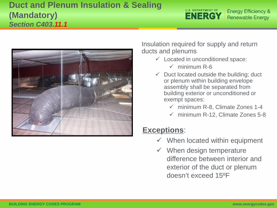
Insulation required for supply and return ducts and plenums
Located in unconditioned space: minimum R-6
Duct located outside the building; duct or plenum within building envelope assembly shall be separated from building exterior or unconditioned or exempt spaces: minimum R-8, Climate Zones 1-4 minimum R-12, Climate Zones 5-8
Duct and Plenum Insulation & Sealing (Mandatory) Section C403.11.1
Exceptions: When located within equipment When design temperature
difference between interior and exterior of the duct or plenum doesn’t exceed 15ºF
BUILDING ENERGY CODES PROGRAM www.energycodes.gov
C403.11.2.1 Low Pressure: Ducts designed to operate at static pressures ≤ 2 in. w.g.
Securely fastened and sealedException: Locking-type longitudinal joints and seams, other than the snap-lock and button-lock types, need not be sealed as specified in this section.
C402.11.2.2 Medium Pressure: Ducts designed to operate at static pressures > 2 in. w.g. but < 3 in. w.g.
Insulated and sealed in accordance with Section C403.11.1
Low & Medium Pressure Duct Systems (Mandatory)Sections C403.11.2.1 and C403.11.2.2

BUILDING ENERGY CODES PROGRAM www.energycodes.gov
Ducts and plenums designed to operate at static pressures > 3 in. w.g. to be
– insulated and sealed– be leak tested in accordance with SMACNA HVAC Air Duct
Leakage Test Manual with the following result Air leakage rate (CL) ≤ 4.0CL = F/P0.65
Where:F = leakage rate cfm per 100 sf of duct surface areaP = the static pressure of the test
Must document test of ≥ 25% of the duct area and meet the requirements
High Pressure Duct Systems (Mandatory)Section C403.11.2.3

BUILDING ENERGY CODES PROGRAM www.energycodes.gov
Piping Insulation (Mandatory) Section C403.11.3
All piping serving heating or cooling system must be insulated in accordance with Table C403.11.3
Minimum Pipe Insulation(thickness in inches)
(Partial table)
11.3.1: Piping insulation exposed to weather shall be protected from sun or moisture damage

BUILDING ENERGY CODES PROGRAM www.energycodes.gov
Exceptions to pipe insulation requirements: Piping internal to HVAC equipment (including fan coil
units) factory installed and tested Piping for fluid in temperature range
60 °F< temp < 105°F Piping for fluid not heated or cooled by electricity or
fossil fuels Strainers, control valves, and balancing valves
associated with piping ≤ 1” in diameter Direct buried piping for fluids ≤ 60°F
Piping Insulation (Mandatory) Section C403.11.3 – Cont’d

BUILDING ENERGY CODES PROGRAM www.energycodes.gov
Systems are to be radiant systems
Controlled by an occupancy sensing device or timer switch So system is automatically deenergized when no occupants are
present
Heating Outside a Building Section C403.12.1 (Mandatory)

BUILDING ENERGY CODES PROGRAM www.energycodes.gov
Snow- and ice-melting systems, supplied through energy service to the building, shall include
automatic controls configured to shut off the system when the pavement temperature is above 50°F (10°C) and no precipitation is falling
an automatic or manual control configured to shut off when the outdoor temperature is above 40°F (4°C)
Snow Melt Systems (Mandatory) Section C403.12.2
Photo courtesy of Ken Baker, K energy

BUILDING ENERGY CODES PROGRAM www.energycodes.gov
Systems such as heat tracing of outdoor piping and heat exchangers, including self-regulated heat tracing to include:• Automatic controls configured to shut off the system when outdoor
air temperatures are > 40°F (4°C) OR• When conditions of the protected fluid will prevent freezing
Freeze Protection System (Mandatory) Section C403.12.3

BUILDING ENERGY CODES PROGRAM www.energycodes.gov
Table C404.2 Minimum Performance of Water-Heating Equipment
Water Heater Types Covered• Electric Storage• Gas and Oil Storage• Instantaneous Water Heaters – Gas and Oil• Hot water boilers – gas and oil• Pool heaters• Unfired storage tanks
Heat Traps (C404.3)Piping Insulation (C404.4)Heated Water Supply Piping(C404.5)Circulation & Temperature Maintenance (C404.6)Demand Recirculation (C404.7)Drain Heat Recovery(C404.8)Pools and Spas (C404.9)Portable Spas (C404.10)All service water heating items are mandatory
Service Water Heating (Mandatory)Section C404

BUILDING ENERGY CODES PROGRAM www.energycodes.gov
• Water-heating equipment and hot water storage tanks must meet Table C404.2
• Efficiency verified through data furnished by manufacturer of equipment or through certification under an approved certification program
• Water-heating equipment intended to be used to provide space heating must meet Table C404.2
Service Water-heating Equipment Performance (Mandatory)Section C404.2

BUILDING ENERGY CODES PROGRAM www.energycodes.gov
• Gas-fired equipment installed in new buildings • Single piece serves entire building with input rating
≥ 1,000,000 Btu/h– Thermal efficiency ≥90%
• Multiple pieces with combined input rating ≥ 1,000,000 Btu/h– Combined input-capacity-weighted-average thermal efficiency ≥90%
Exceptions:• 25% of annual SWH requirement is provided by on-site
renewable energy or site-recovered energy• Input rating of water heaters installed in individual dwelling
units• Individual units with input rating ≤ 100,000 Btu/h not
considered part of building SWH equipment
High Input-rated SWH Systems (Mandatory)Section C404.2.1

BUILDING ENERGY CODES PROGRAM www.energycodes.gov
• Storage tank-type water heaters and hot water storage tanks that have vertical water pipes connecting to inlet and outlet to be provided integral heat traps at those inlets and outlets or have pipe-configured heat traps in piping connected to those inlets and outlets
• Tank inlets and outlets associated with solar water heating system circulation loops not required to have heat traps
Heat Traps (Mandatory)Section C404.3

BUILDING ENERGY CODES PROGRAM www.energycodes.gov
Insulation of Piping (Mandatory) Section C404.4
• Piping from water heater to termination of heated water fixture supply pipe (all recirculation piping) to be insulated per Table C403.11.3
• Both inlet and outlet piping of storage water heater or heated water storage tank• Piping to a heat trap or first 8 ft. of piping, whichever is less
• Piping that is heat traced per Table C403.11.3 or heat trace manufacturer instructions
• Tubular piping insulation installed in accordance with insulation manufacturer’s instructions
• Insulation to be continuous• Except where piping passes through a framing member
• Minimum insulation thickness not to supersede any greater insulation thickness requirements necessary for the protection of piping from freezing temps. or personnel against external surface temps. on the insulation

BUILDING ENERGY CODES PROGRAM www.energycodes.gov
Exceptions to SHW piping insulation:• Tubing from the connection at the termination of the fixture
supply piping to a plumbing fixture or plumbing appliance• Valves, pumps, strainers and threaded unions in piping that is
≤1” in nominal diameter• Piping from user-controlled shower and bath mixing valves to
the water outlets• Cold-water piping of demand recirculation water system• Tubing form hot drinking-water heating unit to the water outlet• Piping at locations where a vertical support of the piping is
installed• Piping surrounded by building insulation with a thermal
resistance ≥ R-3
Insulation of Piping (Mandatory) Section C404.4 – Cont’d

BUILDING ENERGY CODES PROGRAM www.energycodes.gov
For piping from the nearest source of heated water (from the water heater or from the recirculation or trace heated loop) to fixture requires either maximum pipe length (C404.5.1) or maximum pipe volume (C404.5.2) and has maximum flow rated by size• Flow rate through ¼” piping should be ≤ 0.5 gpm• Flow rate through 5/16” piping should be ≤ 1.0 gpm• Flow rate through 3/8” piping should be ≤ 1.5 gpm
Intent is to reduce wasting previously-heated water that has cooled in pipes that do not require insulation
Heated Water Supply Piping (Mandatory)Section C404.5

BUILDING ENERGY CODES PROGRAM www.energycodes.gov
Maximum allowed piping length from nearest source of heated water to termination of the fixture supply pipe:
Where piping contains more than one size, the largest size of pipe within the piping shall be used for determining the max. allowable length of piping in Table C404.5.1• Public lavatory faucet, use “Public Lavatory faucets”
column in Table C404.5.1• All other plumbing fixtures and plumbing appliances use
“Other fixtures and appliances” column in Table C404.5.1
Maximum Allowable Pipe Length Method (Mandatory)Section C404.5.1

BUILDING ENERGY CODES PROGRAM www.energycodes.gov
• Water heaters, circulating water systems, and heat trace temp. maintenance systems to be considered sources of heated water
• Volume from the nearest source of heated water to the termination of the fixture supply pipe as follows:– Public lavatory facet: ≤ 2 ounces– Other plumbing fixtures or plumbing appliances: ≤ 0.5 gallon
Maximum Allowable Pipe Volume Method (Mandatory)Section C404.5.2

BUILDING ENERGY CODES PROGRAM www.energycodes.gov
• Volume to be the sum of the internal volumes of pipe, fittings, valves, meters and manifolds between the nearest source of heated water and the termination of the fixture supply pipe
• Volume determined from the “Volume” column in Table• Volume contained with fixture shutoff valves, within
flexible water supply connectors to a fixture fitting and within a fixture fitting should not be included in the water volume determination
• Heated water supplied by recirculating system or heat-traced piping, the volume should include the portion of the fitting on the branch pipe that supplies water to the fixture
Water Volume Determination (Mandatory)Section C404.5.2.1

BUILDING ENERGY CODES PROGRAM www.energycodes.gov
• Circulation Systems– Controlled pump(s) required– Demand control required (see C404.7)– Gravity and thermosyphon not allowed
• Heat Trace Systems– Energy input adjusted to maintain temperature– Timed or demand automatic controls
• Controls for Hot Water Storage Tank Pumps– Automatic controls limit pump operation to no more than 5
minutes after heater operation• Automatic controls, temperature sensors and pumps
shall be in a location with access.• Manual controls shall be in a location with ready access
Heated-water Circulating and Temperature Maintenance Sys. (Mandatory)Section C404.6

BUILDING ENERGY CODES PROGRAM www.energycodes.gov
• Systems with >1 recirculation pumps that pump water from a heated-water supply pipe back to the heated-water source through a cold-water supply pipe must be a demand recirculation water system
• Demand recirculation water systems to have controls that:– Start pump upon receiving a signal from the action of a user of a
fixture or sensing the flow of hot or tempered water to a fixture fitting or appliance
– Limit the temp. of water entering the cold-water piping (used as a recirculation return) to ≤104ºF
Demand Recirculation Controls (Mandatory)Section C404.7

BUILDING ENERGY CODES PROGRAM www.energycodes.gov
• Must comply with CSA B55.2• Potable water-side pressure loss < 10 psi at maximum
design flow• Group R occupancies, units must meet efficiency in
accordance with CSA B55.1
Note that this provision does not require the use of drain water heat recovery units; it just specifies their performance if used
Drain Water Heat Recovery Units (Mandatory)Section C404.8

BUILDING ENERGY CODES PROGRAM www.energycodes.gov
Heaters (C404.9.1) Readily accessible on-off switch, that is an integral part of heater, mounted
on the exterior of heater or external to within 3 feet of heater in a location with ready access
Switch should not change the setting of the heater thermostat Switches to be in addition to a circuit breaker for the power to the heater Natural gas or LPG fired pool heaters will not have continuously burning
pilot lights
Time switches or other control method (C404.9.2) Automatic controls required to control heaters and pumps on a preset
schedule Exceptions:
• Where public health standards require 24 hour operation• Where pumps are required to operate solar and waste heat recovery pool heating
systems
Note: heaters, pumps and motors with built-in timers meet this requirement
Energy Consumption of Pools and Permanent Spas (Mandatory)Section C404.9

BUILDING ENERGY CODES PROGRAM www.energycodes.gov
Outdoor heated pools and outdoor permanent spas required to have a cover
Cover must be vapor-retardant Or other approved vapor-retardant means
Exception: Pools deriving > 75% of operating season (of not fewer than 3
calendar months) energy for heating from site-recovered such as from heat pump or on-site renewable energy system
Covers (Mandatory) Section C404.9.3
BUILDING ENERGY CODES PROGRAM www.energycodes.gov
Building operations and maintenance information Documents provided to owner and consist of
Manufacturers’ information Specifications and recommendations Programming procedures and data points Narratives And other means of illustrating how the building, equipment and
systems are intended to be installed, maintained and operated
Required regular maintenance actions for equipment and systems to be clearly stated on a readily visible label Label to include title or publication number for the operation and
maintenance manual for that particular model and type of product
Maintenance Information and System CommissioningSection C408.1.1
BUILDING ENERGY CODES PROGRAM www.energycodes.gov
Prior to passing final mechanical and plumbing inspection– Registered design profession to provide evidence of
commissioning and completion
Construction document notes to clearly indicate provisions for commissioning and completion requirements– Permitted to refer to specifications
Copies of all documents to be provided to the owner and made available to code official upon request
Mechanical Systems and SWH Commissioning and CompletionSection C408.2

BUILDING ENERGY CODES PROGRAM www.energycodes.gov
These systems are exempt from commissioning requirements– In buildings where total mechanical equipment capacity is
< 480,000 Btu/h (40 tons) cooling capacity and < 600,000 Btu/h combined service water heating and space-heating capacity
– Included in Section C403.3 that serve individual dwelling units and sleeping units
Mechanical Systems Commissioning and Completion RequirementsSection C408.2 Exceptions

BUILDING ENERGY CODES PROGRAM www.energycodes.gov
Developed by registered design professional or approved agency and include: Narrative description of activities to be accomplished during
each phase of commissioning Including personnel who will do each activity
Listing of specific equipment, appliances or systems to be tested and description of tests to be performed
Functions to be tested, including, but not limited to calibrations and economizer controls
Conditions under which test will be performed At a minimum, testing will affirm winter and summer design
conditions and full outside air conditions Measurable criteria for performance
Commissioning PlanSection C408.2.1
BUILDING ENERGY CODES PROGRAM www.energycodes.gov
HVAC systems balanced per generally accepted engineering standards
Air and water flow rates measured and adjusted to deliver final flow rates within tolerances in product specifications
Test and balance activities to include air system and hydronic system balancing
Systems Adjusting and BalancingSection C408.2.2

BUILDING ENERGY CODES PROGRAM www.energycodes.gov
Each supply air outlet and zone terminal device equipped with means for air balancing per Chapter 6 of the IMC
No discharge dampers used for air-system balancing on constant volume fans and variable volume fans with motors ≥ 10 hp
Air systems balanced in a manner to first minimize throttling losses, then, for fans with system power > 1hp, fan speed adjusted to meet design flow conditions
Exception – fans with motors ≤ 1hp are not required to have a means for air balancing
Air Systems BalancingSection C408.2.2.1

BUILDING ENERGY CODES PROGRAM www.energycodes.gov
Individual hydronic heating and cooling coils equipped with means for balancing and measuring flow
Hydronic systems proportionately balanced in a manner to first minimize throttling losses, then pump impeller to be trimmed or pump speed to be adjusted to meet design flow conditions
Each hydronic system to have either capability to measure pressure across the pump, or test ports at each side of each pump
Exceptions with a means for balancing or measuring flow: Pumps with pump motors ≤ 5hp Where throttling results in ≤ 5% of nameplate hp draw above that
required if the impeller were trimmed
Hydronic Systems BalancingSection C408.2.2.2

BUILDING ENERGY CODES PROGRAM www.energycodes.gov
To demonstrate the installation and operation of components, systems, and system-to-system interfacing relationships in accordance with approved plans and specifications, such that operation, function, and maintenance serviceability for each of the commissioned systems is confirmed
Testing to include all modes and sequence of operation, including under full-load, part-load and the following emergency conditions: All modes as described in the sequence of operation Redundant or automatic back-up mode Performance of alarms, and Mode of operation upon a lost off power and restoration of power
Exception – unitary or packaged HVAC equipment listed in Tables C403.2.3(1) through C403.2.3(3) that don’t require supply air economizers
Functional Performance Testing -EquipmentSection C408.2.3.1

BUILDING ENERGY CODES PROGRAM www.energycodes.gov
HVAC and SWH control systems to be tested to document that control devices, components, equipment, and systems are calibrated, adjusted and operate in accordance with approved plans and specifications
Sequences of operation to be functionally tested to document they operate in accordance with approved plans and specifications
Air economizers to undergo a functional test to determine they operate in accordance with manufacturer’s specifications
Functional Performance Testing –Controls & EconomizersSections C408.2.3.2 & C408.2.3.3

BUILDING ENERGY CODES PROGRAM www.energycodes.gov
Registered design professional or approved agency to complete, certify, and submit to the building owner or owner’s authorized agent
Report to be organized with mechanical and service hot water findings in separate sections to allow independent review. Report shall include Commissioning Compliance Checklist (Figure C408.2.4) and be identified as “Preliminary Commissioning Report” and will identify: Itemization of deficiencies found during testing that haven’t been
corrected at the time of report preparation Deferred tests that can’t be performed at the time of report
preparation due to climatic conditions Climatic conditions required for performance of deferred tests Results of functional performance tests Functional performance test procedures used during commissioning
process, including measurable criteria for test acceptance
Preliminary Commissioning ReportSection C408.2.4

BUILDING ENERGY CODES PROGRAM www.energycodes.gov
Buildings or portions of buildings can’t pass final mechanical inspection until code official has received the Preliminary Commissioning Report from the building owner or owner’s authorized agent
Preliminary Commissioning Report –Acceptance and Copy of ReportSections C408.2.4.1, C408.2.4.2

BUILDING ENERGY CODES PROGRAM www.energycodes.gov
Construction documents to specify that documents described in C408.2.5 be provided to building owner or owner’s authorized agent within 90 days of receipt of certificate of occupancy C408.2.5.1 System balancing report per Section C408.2.2
descriptions of the activities and measurements completed
C408.2.5.2 Final commissioning report with Functional test resultsDisposition of deficiencies found during testing Functional performance test proceduresException – deferred tests which can’t be performed at time of report preparation due to climatic conditions
Documentation RequirementsSection C408.2.5