building finite element analysis programs as...
TRANSCRIPT
Building Finite Element Analysis Programs in
Distributed Services Environment
Jun Peng1 and Kincho H. Law2
Abstract
Traditional finite element analysis (FEA) programs are typically built as standalone desktop software.
This paper describes an Internet-enabled framework that facilitates building a FEA program as distributed
web services. The framework allows users easy access to the FEA core service and the analysis results by
using a web-browser or other application programs. In addition, the framework enables new as well as
legacy codes to be incorporated from disparate sites in a dynamic and distributed manner. To provide
flexible project management and data access, a database system is employed to store project-related
information and selected analysis results. The prototype framework demonstrates that the Internet can
potentially enhance the flexibility and extendibility of traditional FEA programs.
Keywords
Engineering web services; Internet-enabled computing; Finite element program; Engineering database;
Object serialization; Project Management
1 Research Associate, Department of Civil and Environmental Engineering, Stanford University, Stanford, CA 94305. E-mail: [email protected] Professor, Department of Civil and Environmental Engineering, Stanford University, Stanford, CA 94305. Tel: +1-650-725-3154, Fax: +1-650-723-7514, E-mail: [email protected]
1.
1. Introduction
It is well recognized that a significant gap exists between the advances in computing technologies and the
state-of-practice in structural engineering software development. Practicing engineers today usually
perform finite element structural analyses on a dedicated computer using the developments offered by a
finite element analysis (FEA) program. Typically, a FEA program bundles all the procedures and
program kernels that are developed by an individual organization. As technologies and structural theories
continue to advance, FEA programs need to be able to accommodate new developments such as element
formulation, material relations, analysis algorithms, and solution strategies. The need to develop and
maintain large complex software systems in a dynamic environment has driven interest in new
approaches to FEA software design and development. Object-oriented design principles and
programming have been utilized in FEA software development to support better data encapsulation and to
facilitate code reuse. However, most existing object-oriented FEA programs are still rigidly structured.
Extending and upgrading these programs to incorporate new developments and legacy codes remain to be
a difficult task. Moreover, there is no easy way to access computing resources and structural analysis
services distributed in remote sites.
With the advances of computing facilities and the development of communication network in which
computing resources are connected and shared, the programming environment has migrated from relying
on single and local computing environment to developing software in a distributed environment. With
the maturation of information and communication technologies, the concept of building collaborative
systems to distribute web services over the Internet is becoming a reality [14]. Simply defined, web
services are a combination of application and data that can be accessed from any Internet-enabled device
[33]. Using a set of standardized communication protocol, web services can be universally accessed and
deployed, independent of the underlying operation environment. The basic idea behind web services is to
adopt the loosely coupled web programming model to facilitate software component integration. The
2.
goal is to provide a platform for building distributed applications that utilize software components
running on different operating systems and devices. Web services, acting as the adapter for complicated
process components and legacy applications, allow disparate systems to work together.
Following the web services model, we have designed and prototyped an Internet-enabled framework for
the usage and development of a FEA program [26, 28]. The framework adopts distributed service model
to enhance and improve the capability and performance of a FEA program by seamlessly integrating
legacy code and new developments. Developments can be incorporated by directly integrating with the
core as a local module and/or by implementing as a web service. Using the Internet as a communication
channel, the framework provides users the ability to pick and choose the most appropriate methods and
software services for solving a problem. The framework also includes data and project management
functionalities. A database system is employed to store selected analysis results and to provide flexible
data management and data access. Project management functions allow users to access information about
previous analyses of related models stored distributed in different sites. The Internet is utilized as a data
delivery vehicle and a data query language is developed to provide an easy-to-use mechanism to access
the needed analysis results from readily accessible sources.
In the prototype implementation of the Internet-enabled framework, OpenSees [22] is utilized as the finite
element analysis core. OpenSees (Open System for Earthquake Engineering Simulation) is an object-
oriented program for the seismic simulation of structural and geotechnical systems. It is sponsored by
PEER (Pacific Earthquake Engineering Research) center, and is intended to serve as the computational
platform for research in performance-based earthquake engineering. While the prototype implementation
is using OpenSees as the FEA core, the framework is sufficiently general to be incorporated by other FEA
programs. The framework described herein intends to extend FEA programs, such as OpenSees, to better
utilize the Internet as a communication vehicle.
3.

This paper gives a description of the architecture of the Internet-enabled services framework. A modular
design of the framework is introduced and the details of each module are presented. Details of several
software modules have been described elsewhere; for example, element services module is described in
[28] and the database interface module is discussed in [29]. The objective of this paper is to present a
more complete picture of the framework and its application in facilitating FEA program development.
We present two examples to show the flexibility and performance of the Internet-enabled framework.
2. Distributed Services Framework
The distributed engineering service framework is designed to provide developers and users with easy
access to an analysis platform and to incorporate new element technologies, new algorithms, and solution
strategies for structural analyses. By adopting the services model, the FEA program development can
shift the focus from coding to the integration of engineering services.
2.1. Software Integration with Services
Traditionally, large programs are partitioned into subtasks of manageable sizes. The subtasks are
assigned to programmers who code the instructions in certain programming languages. The resulting
program segments are subsequently submitted for integration. As more and more program segments are
pre-constructed and packaged, larger portion of the overall software development effort needs to be spent
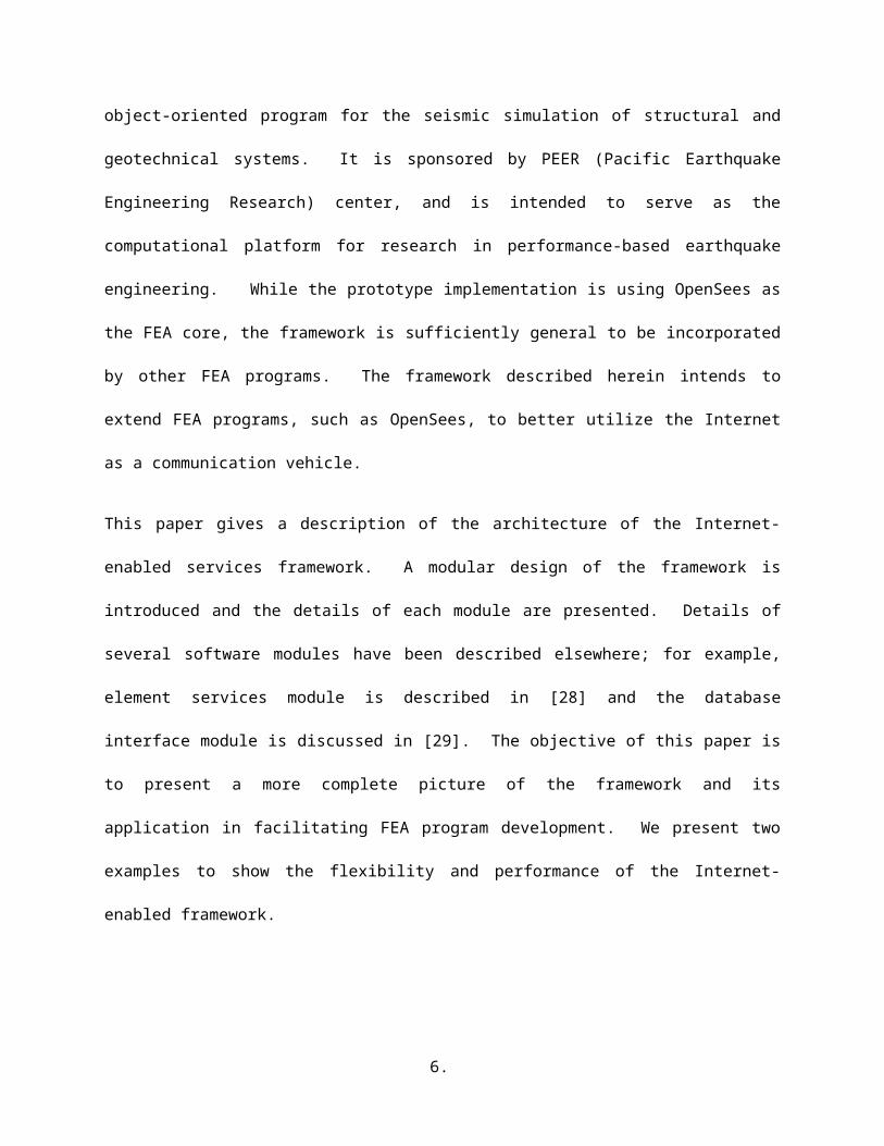
on integration. Such trend is illustrated in Figure 1.
Software integration takes place in many forms. The early attempts are based on code reuse. The
simplest method is to copy the source code to wherever the desired functionality is needed. There are
significant drawbacks to this approach, ranging from compiler incompatibility to difficulty in maintaining
duplicate copies of code. Generally speaking, software integration based on code reuse assumes that the
ownership of the reused software components belongs to the users of the software components. In
addition, the software components are executed on the same machine as the invoker (client) of the
4.
components. To deal with the drawbacks of code reuse, shared libraries are used in place of copied code.
Software components written in a programming language are compiled into shared libraries. The shared
libraries have public interfaces, through which the users can invoke the functions contained in the
libraries.
Coding
Integration
1970 1990 2010
Figure 1. The trend of software development (courtesy of G. Wiederhold, Stanford University)
The development of network computing, especially the emergence of the Internet, allows software
components to be distributed to multiple machines. Each software component runs as a separate process,
communicating with each other by exchanging messages. This software integration model is called the
distributed component model [11]. Assorted tools and standards for assembling distributed computing
applications have been developed over the years. They started as low-level data transmission APIs and
protocols, such as TCP/IP and RPC [2] and have evolved into object-oriented distribution schemes, such
as Object Management Group’s (OMG) Common Object Request Broker Architecture (CORBA) [32],
Microsoft’s Distributed Component Object Model (DCOM) [10] and Sun Microsystems’ Java Remote
Method Invocation (RMI) [30]. These programming tools essentially provide a protocol for transmitting
structured data (and, in some case, actual running code) over a network connection.
As the distributed component model evolves, software components are required to have well-defined
interfaces and constraints, and are normally managed in a decentralized manner. The distributed
components whose interfaces are published on the web are generally referred to as web services [33].
5.
Web services can be regarded as the atomic building blocks for service integration. The functionalities
provided by the web services are composed together to form an integrated service. Although the web
services are distributed and heterogeneous, they are utilized as if they were locally available to the users.
An infrastructure is needed to provide the support for the composition of the service functionalities.
Communication messages are exchanged among the web services to coordinate the execution of the web
services and to exchange data among the web services.
2.2. Framework for FEA Services
The web services model is applied to the development of a FEA program to facilitate software
integration. Certain portions of the FEA program are developed as separate software services, and they
are integrated with the framework through a set of pre-defined protocol.
The design of the framework is focused on the interaction of services and provides the system with a
plug-and-play character [6]. Generally speaking, a service can be viewed as a black-box entity that
provides and/or requires a set of functions (via interfaces) [31]. For a finite element program, element
code is a natural candidate for building as a service. Since there are continuing new developments in
element technologies, developing an element as a separate service can facilitate concurrent development
and eventual incorporation of the new element into the core. In the prototype framework, a database is
used for efficient data storage and flexible post-processing. Since the database module is loosely coupled
with the core program, it can also be constructed as a service. As presented in Figure 2, the current
implementation of the Internet-enabled structural analysis framework has the following modules:
The Analysis Core module consists of a set of basic functional units of a finite element structural
analysis program. Element and material models, solvers, as well as analysis strategies and solution
strategies, are brought into this module to improve the functionality of the core.
6.
The User-Interaction Interface module provides an interface to facilitate the access to the
software platform for the users and developers. The platform can be accessed from either a web-
based interface or other application programs.
The Registration and Naming Service is provided for online application services to register to
the core so that these services can be found and accessed during analysis. The users can obtain
references to certain online application services by querying the Registration and Naming Service.
Two approaches are provided for remote access to element services residing in different
locations. The Distributed Element Service is intended to provide a communication link to remote
element services where the element code is executed. The Dynamic Linked Element Service is
implemented to load the element code, which is built as a dynamic shared library, from a remote
element service site and to link and bind the code with the core at runtime.
The Project and Data Service is built to link with a database system, which can provide
selective data storage and efficient data access, and to facilitate post-processing tasks. Project
management and version control are also supported by the project and data service.
7.
User-InteractionInterface
Registration andNaming Service
DistributedElement ServiceDynamic LinkedElement Service
Analysis Core
Project and DataService
REGISTRY
FTPClient
HttpClient
DynamicShared Library
for Element
RealElementObjects
StubObject
RPC, Java RMI
CORBA
ODBC, JDBC
LAN orInternet 2
Parallel and/ orDistributed Computing
DATABASE
Web Interface
ServerParallelComputer
Workstation
Figure 2. The services of the finite element analysis framework
In this framework, the structural analysis core model, in this case OpenSees [22], is running on a central
server as a compute engine to provide finite element analysis service. A compute engine is a remote
software program that takes a set of tasks from clients, runs them, and returns the result. Parallel and
distributed computing environment, if available, can be employed in the central server to improve the
system performance and makes it more suitable for large-scale engineering simulations [8, 20]. New
analysis strategies and solution strategies can be incorporated into the core to improve the capabilities and
performance of the server. The following present detailed description of other modules of the framework.
3. User-Interaction Services
As shown in Figure 2, the framework can offer users access to the analysis core, as well as the associated
supporting services via the Internet. This client/server computing environment consists of two logical
parts: a server that provides services and a client that requests services from the server. Together, the two
parts form a complete computing framework with a very distinct division of responsibility [18]. One
benefit of this model is the transparency of software services. From a user’s perspective, the user deals
8.
with a single service from a single point-of-contact – even though the actual structural analysis may be
performed in a distributed and collaborative manner. Another benefit is that this framework can widen
the reach of the FEA core program to the users and external developers. The core platform offering the
FEA service stays at the provider’s site, where the software core is developed, kept securely, operated,
maintained and updated.
In the framework, Java Servlet [15] technology is employed to implement the server interface, which
serves as the wrapper to the FEA core. Java Servlets provide a component-based, platform-independent
method for building web-based application, without the performance limitations of CGI (Common
Gateway Interface) programs. For the client application, commercial off-the-shelf (COTS) software
packages would be preferred as the user interface. There are at least two reasons for favoring COTS
software packages as user interfaces than developing a new GUI (Graphical User Interface). First, COTS
software packages generally provide a friendly and easy-to-use interface to the users. The users are
usually more familiar with the interfaces of popular software packages than other interfaces.
Furthermore, many COTS software packages normally have built-in facilities for developers to customize
them. The facilities can make the development process more economical in terms of both development
time and efforts.
3.1. Web-Based User Interface
Client browser programs such as the Internet Explorer and Netscape Navigator allow users to navigate
and access data across machine boundaries. Web browser programs can access certain contents from the
web servers via HTTP (hypertext transfer protocol). The forms in the browsers can provide interactive
capabilities and make dynamic content generation possible. Java effectively takes the presentation
capabilities at the browser beyond simple document display and provides animation and more complex
interactions. In the distributed services framework, a standard World Wide Web browser can be utilized
to interact with the FEA core. Although the use of a web browser is not mandatory for the functionalities
9.
of the framework, using a standard browser interface leverages the most widely available Internet
environment, as well as being a convenient means of quick prototyping.
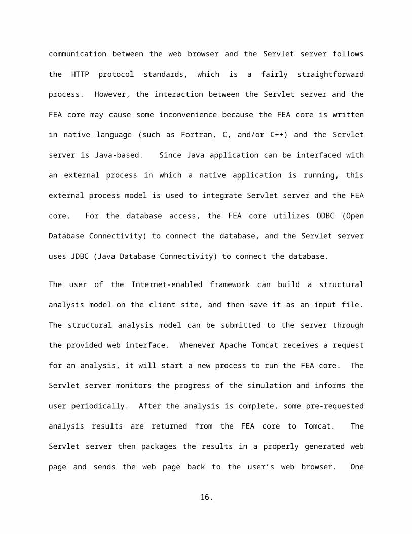
The architecture of the distributed services system with web-based interface is depicted in Figure 3,
which shows the interaction between the web browser and the FEA core. Apache Tomcat [13] is
customized to serve as the Servlet server, which is a middleware to enable the virtual link between the
web browser and the FEA core. Since Java Servlets have built-in supports for web applications, the
communication between the web browser and the Servlet server follows the HTTP protocol standards,
which is a fairly straightforward process. However, the interaction between the Servlet server and the
FEA core may cause some inconvenience because the FEA core is written in native language (such as
Fortran, C, and/or C++) and the Servlet server is Java-based. Since Java application can be interfaced
with an external process in which a native application is running, this external process model is used to
integrate Servlet server and the FEA core. For the database access, the FEA core utilizes ODBC (Open
Database Connectivity) to connect the database, and the Servlet server uses JDBC (Java Database
Connectivity) to connect the database.
The user of the Internet-enabled framework can build a structural analysis model on the client site, and
then save it as an input file. The structural analysis model can be submitted to the server through the
provided web interface. Whenever Apache Tomcat receives a request for an analysis, it will start a new
process to run the FEA core. The Servlet server monitors the progress of the simulation and informs the
user periodically. After the analysis is complete, some pre-requested analysis results are returned from
the FEA core to Tomcat. The Servlet server then packages the results in a properly generated web page
and sends the web page back to the user’s web browser. One feature of this model is that Java Servlet
supports multithreading, so that several users can send requests for analysis simultaneously and the server
is still able to handle them without severe performance degradation.
10.
Web Browser ServletServer
FEA CoreInterface
Internet
Virtual Link
HTTP Protocol
ODBC JDBC
Java NativeInterface
Database
Figure 3. Interaction diagram for the web-based interface
3.2. MATLAB-Based User Interface
For web-based services, all too often analysis result is downloaded from the computational server as a
file, and then put manually (cut and paste plus maybe some cumbersome conversions) into another
program, e.g. a spreadsheet, to perform post processing. For example, if we want to plot a time history
response from a dynamic analysis, we might have to download the response in a data file and then use
MATLAB, Excel, or other software packages to generate a graphical representation. This ad hoc manual
process might also involve data format conversion and software system configuration. It would be more
convenient to directly utilize some popular application software packages to enhance the user interaction
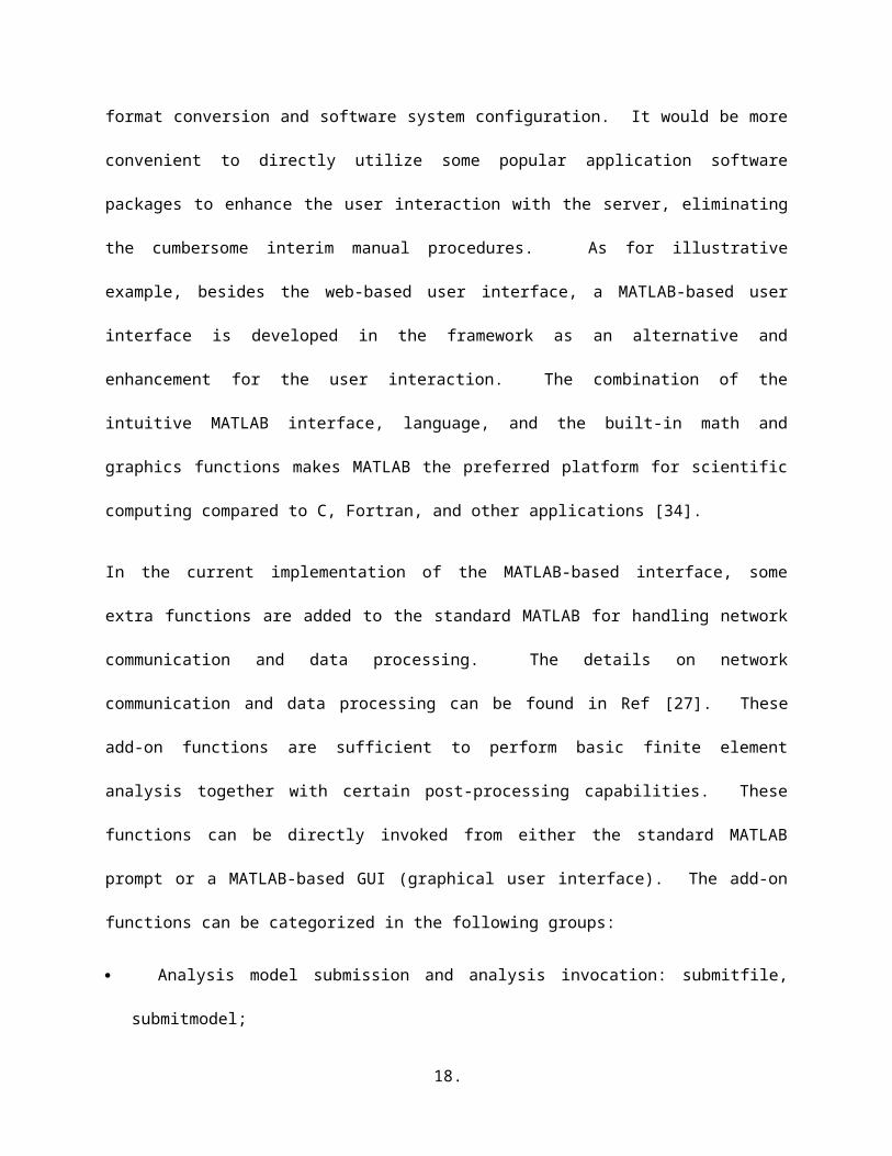
with the server, eliminating the cumbersome interim manual procedures. As for illustrative example,
besides the web-based user interface, a MATLAB-based user interface is developed in the framework as
an alternative and enhancement for the user interaction. The combination of the intuitive MATLAB
interface, language, and the built-in math and graphics functions makes MATLAB the preferred platform
for scientific computing compared to C, Fortran, and other applications [34].
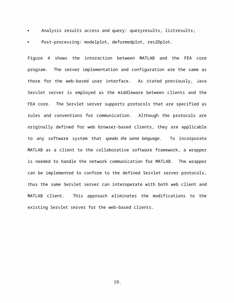
In the current implementation of the MATLAB-based interface, some extra functions are added to the
standard MATLAB for handling network communication and data processing. The details on network
communication and data processing can be found in Ref [27]. These add-on functions are sufficient to
11.
perform basic finite element analysis together with certain post-processing capabilities. These functions
can be directly invoked from either the standard MATLAB prompt or a MATLAB-based GUI (graphical
user interface). The add-on functions can be categorized in the following groups:
Analysis model submission and analysis invocation: submitfile, submitmodel;
Analysis results access and query: queryresults, listresults;
Post-processing: modelplot, deformedplot, res2Dplot.
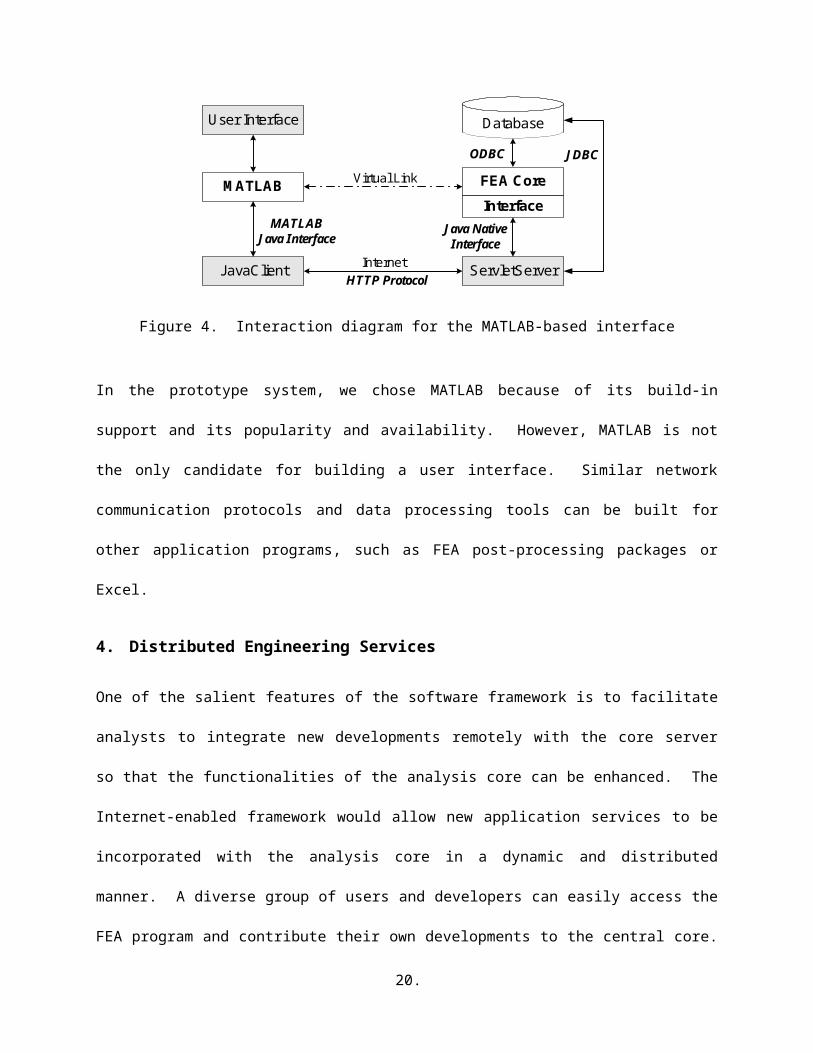
Figure 4 shows the interaction between MATLAB and the FEA core program. The server
implementation and configuration are the same as those for the web-based user interface. As stated
previously, Java Servlet server is employed as the middleware between clients and the FEA core. The
Servlet server supports protocols that are specified as rules and conventions for communication.
Although the protocols are originally defined for web browser-based clients, they are applicable to any
software system that speaks the same language. To incorporate MATLAB as a client to the collaborative
software framework, a wrapper is needed to handle the network communication for MATLAB. The
wrapper can be implemented to conform to the defined Servlet server protocols, thus the same Servlet
server can interoperate with both web client and MATLAB client. This approach eliminates the
modifications to the existing Servlet server for the web-based clients.
JavaClient ServletServer
FEA CoreMATLABInterface
Internet
Virtual Link
User Interface
ODBC
HTTP Protocol
JDBC
MATLABJava Interface
Java NativeInterface
Database
Figure 4. Interaction diagram for the MATLAB-based interface
12.
In the prototype system, we chose MATLAB because of its build-in support and its popularity and
availability. However, MATLAB is not the only candidate for building a user interface. Similar network
communication protocols and data processing tools can be built for other application programs, such as
FEA post-processing packages or Excel.
4. Distributed Engineering Services
One of the salient features of the software framework is to facilitate analysts to integrate new
developments remotely with the core server so that the functionalities of the analysis core can be
enhanced. The Internet-enabled framework would allow new application services to be incorporated with
the analysis core in a dynamic and distributed manner. A diverse group of users and developers can
easily access the FEA program and contribute their own developments to the central core. By providing a
modular infrastructure, services can be added or updated without the recompilation or reinitialization of
the existing services.
The distributed services integration can be roughly categorized as coarse-grained integration or fine-
grained integration. Each message between distributed services has certain performance overhead, such
as the time for parameter marshalling and unmarshalling, the initialization cost, the network latency, and
other types of associated performance penalties. Since coarse-grained integration bundles communication
messages between distributed services, it generally has better performance than fine-grained integration
for composition of the same services. For illustration purpose, this paper focuses on the service
integration of elements to the analysis core. There are two types of online element services: namely
distributed element service (fine-grained integration) and dynamic shared library element service (coarse-
grained integration). Which form of services to be used for linking the element with the core is up to the
developers for their convenience and other considerations. As long as the new element conforms to the
standard interface, it will be able to communicate with the analysis core. As opposed to the traditional
statically linked element library, the online element services will not expose the source code to the core.
13.
Therefore, the framework allows the building of proprietary element services and facilitates the linking of
legacy applications. The infrastructure for supporting the integration of these two types of online element
service is presented in this paper. Similar infrastructure and communication protocol can be designed and
implemented to link other types of online modular services, e.g. material services, solution algorithms
services, and analysis strategies services, etc.
4.1. Registration and Naming Service
To support distributed services with many participants, the core server must be able to differentiate the
services and locate appropriate services for specific tasks. One approach to achieve this goal is to create a
Registration and Naming Service (RANS), where an agent or participant could register its service with a
unique service name and location. The RANS allows names to be associated with services, and would be
responsible for mapping the named services to the physical locations. With the RANS, the users can
obtain references to the services they wish to use. Clients may query the RANS to obtain the associated
service and the description of the service. Figure 5 shows a distributed service registering its name and
property to the RANS server. Clients can then query the RANS using a predetermined name to obtain the
associated distributed service.
<name_1, property_1>. . .
<name_n, property_n>
<name_1, property_1>. . .
<name_n, property_n>
RANS
Client
DistributedService
register(name, property)
query(name)
property
Figure 5. Registering and resolving names in RANS
The RANS is a service located on the central server to handle the user requests for registering or querying
for a distributed service. In the prototype system, the RANS is implemented in Java, and a Java class
Identity is defined to record the service identity. Each service is identified by a name property and an id
14.
property. The string name property is a descriptive name that can be used to specify the service. The
integer id is an internal identifier generated to uniquely tag each service. We have designed the Identity
class to implement the Java Serializable interface [4], so that Identity objects can be passed back and forth
on the network as a data stream. One important method of the Identity class is equals(), which can be
used to identify if two identities are the same. Besides the name and id fields, the Identity class also
stores other service-related information, for example, the service type, IP address, the port number, and
the owner of the service, etc.
In the framework, after a distributed element service is developed and tested, the author of the element
may release the element for other users. To make the element accessible to others, the first step the
developer needs to perform is to register the element service to the RANS server. The registration can be
done through a web-based interface, which sends the service information to the Java Servlet server, and in
turn invokes certain methods of the RANS service.
4.2. Distributed Element Services
A key feature of the framework is the interchangeability of components and the ability to integrate
existing libraries and new components into the analysis core without the need to dramatically change the
existing code. In an object-oriented FEA program, introducing a new type of element generally consists
of creating a new subclass for a specific element [23]. This local object-computing paradigm can be
extended to support distributed services. Instead of only using the objects that reside exclusively on one
local computer, the framework also utilizes distributed objects to allow the building of a distributed
application to facilitate new element development.
The essential requirements in a distributed object system are the ability to create and invoke objects on a
remote host or process, and interact with them as if they were objects within the same local process. To
do so, some kind of message protocol is needed for sending requests to remote services to create new
objects, to invoke methods on these objects, and to delete the objects when they are done. As discussed
15.
earlier, assorted tools and protocols are provided to transmit structured data over the network, such as
CORBA [32], DCOM [10], and Java RMI [30]. There are also web services technologies for facilitating
distributed service composition, for example, Microsoft .NET [16] and SOAP [3].
In the prototype implementation, Java’s Remote Method Invocation (RMI) is chosen to handle
communication for the distributed element services over the Internet. Java RMI enables a program in one
Java Virtual Machine (VM) to make method calls on an object located on a remote server machine. RMI
allows distributing computational tasks across a networked environment and thus enables a task to be
performed on the machine most appropriate for the task [12]. The design goal for the RMI architecture is
to create a Java distributed object model that integrates naturally into the local object model. The easy-to-
use interface and the language features in Java help programmer to write client/server components that
can interoperate easily. Java RMI also provides a high level of security and reliability in developing a
distributed environment. Therefore, Java RMI is chosen as a convenient environment to build the
prototype system. However, compared with distributed computing environment with a design goal of
supporting heterogeneous systems (such as CORBA and Microsoft .NET), there is one challenge for
building distributed element service by using Java RMI: incorporating legacy systems in the Java
infrastructure. The original FEA core system is written in C++, and partly written in C and Fortran
(referred to as native language in Java terminology). A communication support between Java and other
languages needs to be provided by using Java Native Interface (JNI) [19]. By programming through the
JNI, we can use Java objects to access native methods and libraries. However, JNI has fairly complicated
interfaces and a devious invocation mechanism. As a result, JNI may incur certain performance overhead
to the overall system.
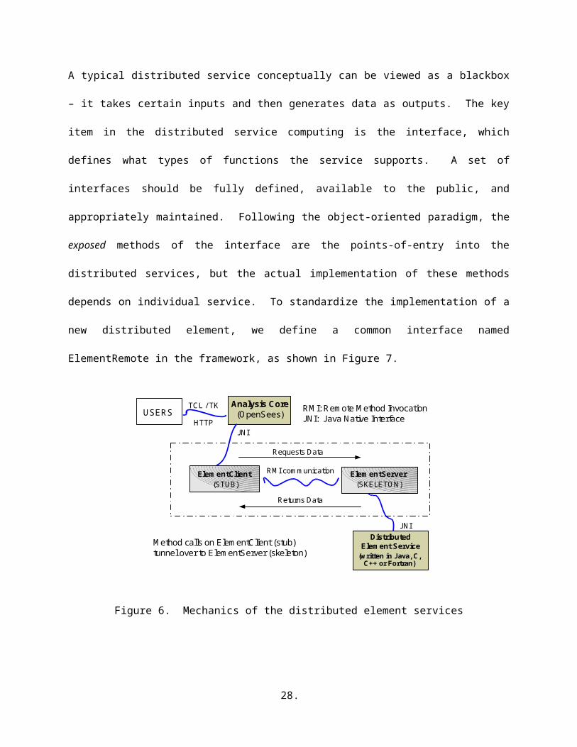
Figure 6 illustrates the mechanics of the distributed element services infrastructure. Within the
infrastructure, an element service can be written in any popular programming languages: Java, C, C++, or
Fortran. As long as the element service conforms to the defined protocol, the service can participate in
the framework. The skeleton, which is the object at the server site, receives method invocation requests
16.
from the client. The skeleton then makes a call to the actual object implemented on the server. The stub
is the client’s proxy representing the remote object and defines all the interfaces that the remote object
supports. The actual element code of a distributed element service resides in the service provider’s site.
The developed element service communicates with the analysis core through a communication layer,
which consists of a stub and a skeleton. A remote method call initiated by the analysis core invokes
certain method on the element service via the communication layer. For example, the analysis core may
issue a remote method invocation to send the input data of an element (e.g. geometry, nodal coordinates,
Young’s modulus, and Poisson ratio, etc.) to the element service. Later on, when the core needs certain
element data, for example a stiffness matrix, the analysis core requests the service provider through a
sequence of remote method invocations. The computation (e.g. the forming of the stiffness matrix of an
element) is performed at the service provider’s site and the results are then sent back to the core as the
return value of the remote method invocations.
A typical distributed service conceptually can be viewed as a blackbox – it takes certain inputs and then
generates data as outputs. The key item in the distributed service computing is the interface, which
defines what types of functions the service supports. A set of interfaces should be fully defined, available
to the public, and appropriately maintained. Following the object-oriented paradigm, the exposed
methods of the interface are the points-of-entry into the distributed services, but the actual
implementation of these methods depends on individual service. To standardize the implementation of a
new distributed element, we define a common interface named ElementRemote in the framework, as
shown in Figure 7.
17.
USERS
ElementClient(STUB)
ElementServer(SKELETON)
RMI communication
DistributedElement Service
(written in Java, C,C++ or Fortran)
JNI
JNI
Requests Data
Returns Data
Analysis Core(OpenSees)
RMI: Remote Method InvocationJ NI: J ava Native InterfaceHTTP
TCL / TK
Method calls on ElementClient (stub)tunnel over to ElementServer (skeleton)
Figure 6. Mechanics of the distributed element services
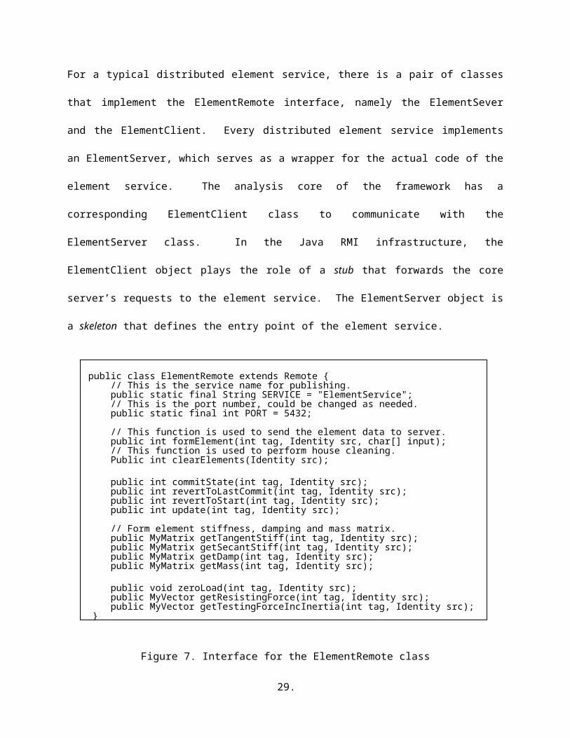
For a typical distributed element service, there is a pair of classes that implement the ElementRemote
interface, namely the ElementSever and the ElementClient. Every distributed element service
implements an ElementServer, which serves as a wrapper for the actual code of the element service. The
analysis core of the framework has a corresponding ElementClient class to communicate with the
ElementServer class. In the Java RMI infrastructure, the ElementClient object plays the role of a stub that
forwards the core server’s requests to the element service. The ElementServer object is a skeleton that
defines the entry point of the element service.
public class ElementRemote extends Remote { // This is the service name for publishing. public static final String SERVICE = "ElementService"; // This is the port number, could be changed as needed. public static final int PORT = 5432;
// This function is used to send the element data to server. public int formElement(int tag, Identity src, char[] input); // This function is used to perform house cleaning. Public int clearElements(Identity src);
public int commitState(int tag, Identity src); public int revertToLastCommit(int tag, Identity src); public int revertToStart(int tag, Identity src); public int update(int tag, Identity src);
// Form element stiffness, damping and mass matrix.
18.
public MyMatrix getTangentStiff(int tag, Identity src); public MyMatrix getSecantStiff(int tag, Identity src); public MyMatrix getDamp(int tag, Identity src); public MyMatrix getMass(int tag, Identity src);
public void zeroLoad(int tag, Identity src); public MyVector getResistingForce(int tag, Identity src); public MyVector getTestingForceIncInertia(int tag, Identity src);}
Figure 7. Interface for the ElementRemote class
4.3. Dynamic Shared Library Element Services
The distributed element service model described in the previous section is flexible and convenient.
However, this approach does carry some overhead on remote method invocation, which is generally more
expensive than a local method procedure call. The system performance decreases because a remote
method has to be invoked for accessing every distributed element. A dynamic shared library (or simply a
shared library) element service is designed to improve the system performance without losing the
flexibility and other benefits of the distributed services. Instead of being compiled to a static library and
merged to the core server, an element service is built as a dynamic shared library and located on the
element service provider’s site. During the system runtime, the installed shared library can be
automatically downloaded to the core server and linked with the FEA core. The shared library element
service allows the replacement of an element service without reinitiating the core server.
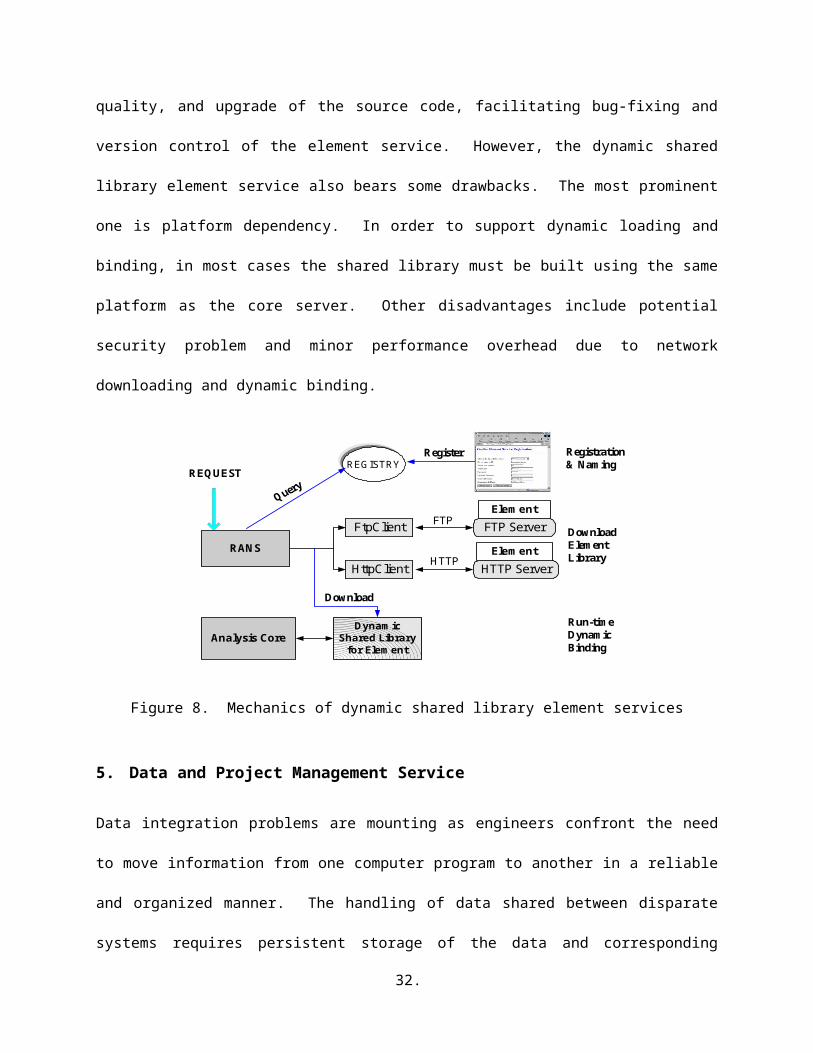
The mechanics of the dynamic shared library element service is depicted in Figure 8. In this approach,
the element code is built in the form of a dynamic shared library conforming to a standard interface. The
developed shared library can be placed on an FTP server or an HTTP server on the element service
provider’s site; and the service needs to be registered to the analysis core’s RANS server. During a
structural analysis, if the core needs the element, the RANS server will be queried to find the pertinent
information about this element service. After the location of the element service is found, the shared
library is downloaded from the service provider’s site and is placed on a predetermined location on the
19.
core’s computer. The downloaded shared library can then be dynamically accessed at runtime by the
analysis core whenever the element is needed. Since the RANS server keeps track of the modifications
and versioning of the shared library element services, the replacement of an element service can be easily
achieved by downloading the updated copy of the shared library.
There are many advantages for the shared library element services. One advantage of linking
dynamically with shared libraries over linking statically with static libraries is that the shared library can
be loaded at runtime, so that different services can be replaced at runtime without re-compilation and re-
linking with the application. Another benefit of using dynamic shared library is that the shared library is
in binary format. The binary format guarantees that the source code of the element will not be exposed to
the core server, making the building of proprietary software components easier. This also implies that the
element developer controls the maintenance, quality, and upgrade of the source code, facilitating bug-
fixing and version control of the element service. However, the dynamic shared library element service
also bears some drawbacks. The most prominent one is platform dependency. In order to support
dynamic loading and binding, in most cases the shared library must be built using the same platform as
the core server. Other disadvantages include potential security problem and minor performance overhead
due to network downloading and dynamic binding.
FTP Server
HTTP Server
REGISTRY
FtpClient
HttpClient
RANS
DynamicShared Library
for Element
Element
Element
Analysis Core
Register Registration& Naming
DownloadElementLibrary
Run-timeDynamicBinding
FTP
HTTP
REQUEST
Download
Figure 8. Mechanics of dynamic shared library element services
20.
5. Data and Project Management Service
Data integration problems are mounting as engineers confront the need to move information from one
computer program to another in a reliable and organized manner. The handling of data shared between
disparate systems requires persistent storage of the data and corresponding interfaces to access the data.
As shown in Figure 2, a project and data service is designed as one module of the Internet-enabled
framework to provide users with easy and efficient access to project information and structural analysis
results [29]. The data management service would allow the users to query the core server for useful
analysis results, and the information retrieved from the database through the core server is returned to the
users in a standard format. The project management service facilitates the users to manage and to
collaborate on the analysis of a structure.
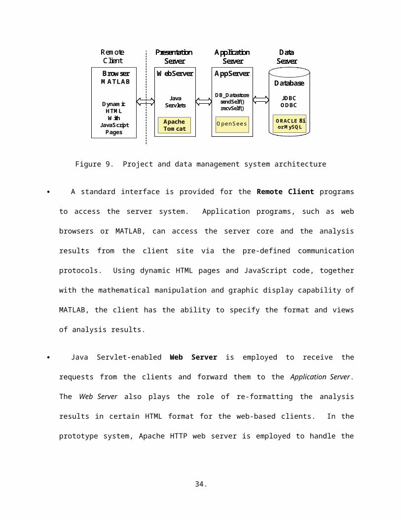
5.1. Multi-Tiered Architecture
Figure 9 depicts the architecture of the data management service. A multi-tiered architecture is employed
instead of the traditional two-tier client-server architecture. The multi-tiered architecture provides a
flexible mechanism to organize distributed services. Since components in the system are modular and
self-contained, they could be designed and developed separately. The multi-tiered data management
system has the following components:
Browser WebServerDatabase
AppServer
J avaServlet
OpenSees
DynamicHTMLWith
JavaScriptPages
ORACLE8i
ApacheWith
TomcatStored
Procedure
ODBCJDBC
PresentationServer
ApplicationServer
DataServer
Browser WebServerDatabase
AppServer
J avaServlet
OpenSees
DynamicHTMLWith
JavaScriptPages
ORACLEApacheWith
TomcatStored
Procedure
RemoteClient
PresentationServer
ApplicationServer
DataServer
BrowserMATLAB
JavaServlets
WebServer
JDBCODBC
DatabaseDB_Datastore
sendSelf()recvSelf()
AppServer
ApacheTomcat
OpenSees
DynamicHTMLWith
JavaScriptPages
ORACLE 8ior MySQL
PresentationServer
ApplicationServer
DataServer
Browser WebServerDatabase
AppServer
J avaServlet
OpenSees
DynamicHTMLWith
JavaScriptPages
ORACLE8i
ApacheWith
TomcatStored
Procedure
ODBCJDBC
PresentationServer
ApplicationServer
DataServer
Browser WebServerDatabase
AppServer
J avaServlet
OpenSees
DynamicHTMLWith
JavaScriptPages
ORACLEApacheWith
TomcatStored
Procedure
RemoteClient
PresentationServer
ApplicationServer
DataServer
BrowserMATLAB
JavaServlets
WebServer
JDBCODBC
DatabaseDB_Datastore
sendSelf()recvSelf()
AppServer
ApacheTomcat
OpenSees
DynamicHTMLWith
JavaScriptPages
ORACLE 8ior MySQL
PresentationServer
ApplicationServer
DataServer
Figure 9. Project and data management system architecture
21.
A standard interface is provided for the Remote Client programs to access the server system.
Application programs, such as web browsers or MATLAB, can access the server core and the
analysis results from the client site via the pre-defined communication protocols. Using dynamic
HTML pages and JavaScript code, together with the mathematical manipulation and graphic display
capability of MATLAB, the client has the ability to specify the format and views of analysis results.
Java Servlet-enabled Web Server is employed to receive the requests from the clients and
forward them to the Application Server. The Web Server also plays the role of re-formatting the
analysis results in certain HTML format for the web-based clients. In the prototype system, Apache
HTTP web server is employed to handle the requests from the users, and Apache Tomcat is employed
as the Java Servlet server.
The Application Server is the middle layer for handling communication between the Web Server
and the Data Server. The Application Server also provides the core functionalities for performing
analyses and generating analyses results. In the Internet-enabled framework, the FEA core is situated
in the Application Server.
A COTS database system is utilized as the Data Server for the storage and retrieval of selected
analysis results. Examples of COTS database systems include Oracle [17], Access [1], and MySQL
[9]. The communication between the Application Server and the Database is handled via the
standard data access interfaces based on Open Database Connectivity (ODBC) that most COTS
database systems provide. ODBC makes it possible to access different database systems with a
common language.
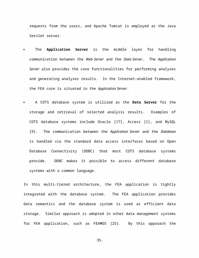
In this multi-tiered architecture, the FEA application is tightly integrated with the database system. The
FEA application provides data semantics and the database system is used as efficient data storage.
Similar approach is adopted in other data management systems for FEA application, such as FEAMOS
22.

[25]. By this approach the application internally gains access to general database capabilities, tightly
coupled to the application itself.
5.2. Selective Data Storage
A typical finite element analysis generates large volume of data. The analysis results can be saved and
retrieved in two ways. One approach is to pre-define all the required data and save only those pre-defined
data during the analysis. However, if analysis results other than the pre-defined ones are needed, a
complete re-analysis is needed to generate those analysis results. For a nonlinear dynamic analysis of a
large structural model, the analysis needs to be restarted from scratch, which is an expensive process in
terms of both processing time and storage requirement. The other approach is simply dumping all the
interim and final analysis data into files, which are then utilized later to retrieve the required results as a
postprocessing task. The drawbacks of this approach are the substantial amount of storage space and the
potential poor performance due to the expensive search on the large data files.
There is an alternative to store only selected data. Many approaches can be adopted for selecting the data
to be stored during an analysis. The objective is to minimize the amount of storage space without
severely sacrificing performance. For many commercial FEA packages, such as ANSYS and ABAQUS,
two types of output files can be created during an analysis. One type is a results file containing results for
postprocessing. The results file is the primary medium for storing results in computer readable form. The
results file can also be used as a convenient medium for importing analysis results into other
postprocessing programs. Users are able to specify in the analysis input the kind of data to be saved in
the results file. The other type of output file is a restart file containing results for continuing an analysis.
The restart file essentially stores the state of an analysis model so that it can be used for subsequent
continuation of an analysis. For a nonlinear dynamic analysis, users are allowed to specify the frequency
at which results will be written to the restart file.
23.
In the data management service proposed in this work, these two types of data storage (results and restart)
are also supported. However, they are carried out in a different fashion. The data management service
allows the collection of certain information to be saved as the analysis progresses, e.g. the maximum
nodal displacement at a node or the time history response of a nodal displacement. A new type of class,
e.g. a Recorder, is introduced to facilitate recording and storing data during an analysis. The purpose is to
keep track of the progress of an analysis and output the users’ pre-specified results. Besides the recording
functionalities, the data access system also has the restart capability. Certain selected data are stored
during the analysis that allows the analysis results to be restored as needed. The selected data need to be
sufficient for the re-computation during postprocessing. In the data access system, we use object
serialization [4] to facilitate the restart function. Ordinarily, an object lasts no longer than the program
that creates it. In this context, persistence is the ability of an object to record its state so that the object
can be reproduced in the future, even in another runtime environment. Object serialization allows the
internal data structures of an object to be mapped to a serialized representation that can be sent, stored,
and retrieved by other applications. Through object serialization, the object can be shared outside the
address space of an application by other application programs. A persistent object might store its state in
a file or a database, which is then used to restore the object in a different runtime environment. Consider
a Truss element as an example, its nodes, dimension, number of DOFs, length, area, and material
properties can be saved in a file or a database system during an analysis. Based on these stored data, a
copy of the Truss object can be restored, and the stiffness matrix of the Truss element can then be re-
generated.
The restart function introduced in the framework is different from those supported by current commercial
FEA programs (e.g. ANSYS, ABAQUS, etc.). For most commercial FEA programs, the data saved in the
restart file must conform to certain pre-defined data format. The restart function in the framework, on the
other hand, relies on object serialization. As long as a replica of an object can be recreated with the saved
data, the developer of the class can freely decide what kind of data to be saved and manipulate the saved
24.

data. This decentralized development control provides great flexibility and extendibility to the
developers, especially in a distributed and collaborative development environment. Furthermore, the
restart file of most commercial FEA programs is organized as a sequential file. On the other hand, the
restart data saved in the framework can be retrieved randomly, i.e., the state of a particular object is
accessed through a key value. Therefore, a particular object or a sub-model of the finite element model
can be easily restored without retrieving unnecessary data.
5.3. Data Storage Scheme
In the data access system, a COTS database system is associated with the FEA core to provide data
storage and facilitate data query. Because COTS database systems generally have indexing capability to
support key-based searching, the required data retrieval mechanism of the data management service is one
reason that makes COTS database systems preferable to file systems. For a typical structural analysis, the
analysis core stores selected data into the database. During the post-processing phase, a request from a
client for certain analysis result is submitted to the analysis core instead of directly querying the database.
Upon receiving the request, the analysis core automatically queries the database for saved data to
instantiate the required new objects. If necessary, these objects are initialized to restart the analysis to
generate the requested results. Compared with re-performing the entire analysis to obtain the data that are
not pre-defined, re-computation is more efficient since only a small portion of the program is executed
with the goal of fulfilling the request. As opposed to storing all the data needed to answer all queries, the
selective storage strategy can significantly reduce the amount of data to be stored in the data management
system.
One example to reduce the storage space is a strategy named Sampling At a Specified Interval (SASI),
which can be applied to nonlinear incremental analyses to dramatically reduce the storage space
requirement. Both incremental single-step methods and some of the incremental-iterative methods (such
as Newton-Raphson scheme) are common for nonlinear incremental analysis [21]. From these nonlinear
25.
analysis methods, it can be seen that the state of the model at a certain step is only dependent on the state
of the model at the immediate previous step. Based on this observation, a discrete storage strategy can be
applied to nonlinear structural analysis. More specifically, instead of storing all the analysis results, the
state information of a nonlinear analysis is saved at a specified interval (e.g. every 10 steps or other
appropriate number of steps, instead of every step). The key requirement is that the saved information
needs to be sufficient to restore the analysis model to that particular step. As discussed earlier, object
serialization can be used to guarantee this requirement.
During the postprocessing phase, the data requests are forwarded from the remote client site to the
analysis core. After receiving the requests, the analysis core will search the database to find the closest
sampled point that is less than or equal to the queried step. The core then fetches the data from the
database to obtain the necessary state information for that step. These fetched data will be sufficient to
restore the model to that sampled step. After the model restores itself to the required step, the core can
progress itself to reach the queried time or incremental step. Once the information of the queried step is
restored, data queries regarding information at that step can be processed by calling the corresponding
functions of the restored model objects. Since the information is only saved at the sampled steps, the total
storage space is dramatically reduced as opposed to saving the entire analysis results at all the steps.
Compared with restarting the analysis from the original step, the processing time needed by using SASI
(i.e. restarting the analysis from a sampled step) can potentially be reduced significantly. The same
strategy can also be designed for other types of analyses (such as for time dependent problems).
5.4. Data Query Processing
For finite element programs, the post-processing functions need to allow the recovery of analysis results
and provide extensive graphical and numerical tools for gaining an understanding of results. In this
sense, querying the analysis results is an important aspect and query languages need to be constructed to
26.
retrieve the analysis results. In the data management service, a data query processing system is provided
to support the interaction with both humans and other application programs.
A data query language is defined to facilitate data retrieval as well as invoking post-processing
functionalities. A query language can be used to define, manipulate, and retrieve information from a
database. For instance, for retrieving some particular result of an analysis, a query can be formed in the
high-level and declarative query language that satisfies the specified syntax and conditions. In the data
management service, the DQL (data query language) is defined to query the analysis results together with
invoking certain post-processing computation. Combining general query language constructs with
domain-related representations provides a more problem-oriented communication. [24]. The defined
DQL and the programmed procedures have at least two features:
It provides a unified data query language. No matter what kind of form the data is presented
(whether a relation or a matrix), the data is treated in the same way. It is also possible to make query
on specific entries in a table or individual elements of a matrix.
The DQL language provides the same syntax for both terminal users (from command lines) and
for those who use the DQL within a programmed procedure. This leads to the ease of communication
between the client and the server, and can save programming efforts when linking the data access
system with other application programs.
As discussed earlier, a hybrid storage strategy is utilized for storing nonlinear dynamic simulation results.
For different type of stored data (results regarding a certain time step or time history responses), different
query commands are needed and different actions are taken. These query commands can be issued using
the web browser interface or directly from an application program such as MATLAB. Several commonly
used features of the DQL are illustrated below.
27.
First, we will illustrate the queries related to a particular time step. To query the data related to a
specified time step, the information needs to be restored to that time step. For example, we can use
command
RESTORE 462
which will trigger the restoration of the information to time step 462.
After the model has been restored to the time step, queries can be issued for detailed information. As an
example, we can query the displacement from Node number 4,
SELECT disp FROM node=4;
The analysis result can also be queried from other objects, such as Element, Constraint, and Load. For
example,
SELECT tangentStiff FROM element=2;
returns the stiffness matrix of Element number 2.
Besides the general queries, two wildcards are provided. One is the wildcard ‘*’ that represents all
values. For instance, if we want to obtain the displacement from all the nodes, we can use
SELECT disp FROM node=*;
The other wildcard ‘?’ can be used on certain object to find out what kind of queries it can support. For
example, the following query
SELECT ? FROM node=1;
returns
Node 1:: numDOF crds disp vel accel load mass *
Another class of operations is aggregation. By aggregation, we mean an operation that forms a single
value from a list of related values. The following are five common operators that apply to a list of related
values and produce a summary or aggregation of that list:
28.
SUM, the sum of the values in the list;
AVG, the average of values in the list;
MIN, the least value in the list;
MAX, the greatest value in the list;
COUNT, the number of values in the list.
The aggregation operators are particularly convenient for producing simple summary results.
The second type of queries is used to access the pre-defined analysis results, especially the time history
responses. The users can specify in the input file what kind of information they want to keep track of.
During the structural analysis, these pre-defined data are stored in files in the central server site. The files
saved in the server can be queried and downloaded by the clients. The queried time history responses can
then be saved into files in the client site for future post-processing applications. For instance, if we want
to save the displacement time history response of a particular node, the following query command can be
issued to the server
SELECT time disp FROM node=1 AND dof=1
SAVEAS node1.out;
If the data are pre-defined in the input file and saved during the analysis phase, the query can return the
corresponding saved analysis results. Otherwise, a re-computation is triggered to generate the requested
time history response.
5.5. Project Management
In nonlinear dynamic analysis, extensive study of a structure involves numerous simulations to be
performed. Typically, model calibration requires several analysis models to be constructed with different
model characteristics. To conduct a probability analysis, earthquake records with different magnitudes
29.
are applied to the same analysis model. Since there are numerous simulations for the same structure, a
project management mechanism is needed to store and manage model information and simulation results.
The Internet-enabled framework provides users with a project management service that enables
collaborative work on a specific structure model. In this work, we refer to project as a particular analysis
model, case as a specific simulation, and owner as the user who performs simulation on a case and
manages the simulation results. Following this terminology, a structure could potentially result in several
projects, with each representing one analysis model. Each project could incorporate many cases by
applying different earthquake records or using different analysis strategy on the same model.
Due to the large amount of model data and simulation results of a structure, it is infeasible to store all
analysis related data in a single computer. Therefore, a centralized control-distributed data storage
scheme is adopted in the project management service. Specifically, a central server stores all of the
project background information (such as size of the model, the types of finite elements, specific boundary
conditions, etc.) and the locations of projects and cases. The actual analysis data (such as finite element
models, documents, simulation results, etc.) of each case resides on disparate sites and managed by
different owner. The distributed nature of data storage allows the owner to perform simulation and
manage the results locally.
There are several other capabilities of the project management service in the framework. One important
feature among others is network transparency, which results in a unified front-end representation to users,
regardless of where the data is stored. The project management service provides a web interface for
retrieval of project background information, documents, messages, and simulation results. By doing so,
the project management service creates an environment where users only need to deal with a single
server. The complexity of the distributed data storage is hidden from the users. Besides network
transparency, other features of the project management service are access control and version control
capabilities. Access control is incorporated to differentiate users and to allow them access projects based
30.
on their privileges. For instance, owner of a project has full control on all the project data, while some
users are only allowed to access the data without the ability to modify. Version control is implemented
with the project management service to keep track of the modifications to the analysis models and to
present the difference between projects.
6. Examples
A prototype of the collaborative framework for structural analysis is implemented using Sun workstations
as the hardware platform. The FEA core is based on OpenSees (a C++ program), and the employed
database system is Oracle 8i. Apache HTTP server is served as the web server, and Apache Tomcat 4.0 is
utilized as the Java Servlet server. MATLAB 6.0 and a standard web-browser are employed as the user
interfaces for accessing the analysis results and project-related information.
6.1. Example 1: An Eighteen-Story One-Bay Frame
The first example is a structural model of 18 story two-dimensional one bay frame. The story heights are
all 12 feet and the span is 24 feet. Figure 10 shows a sketch of the structural model. As illustrated in the
figure, all the beams and columns are modeled as ElasticBeamColumn elements and the hinging is
modeled with zero-length elasto-plastic rotational element. A nonlinear dynamic analysis is performed
on the model using Newton-Raphson analysis algorithm. The input earthquake record is from the 1994
Northridge earthquake recorded at the Saticoy St. Station, California. A time history plot of the
earthquake record is also shown in Figure 10.
31.
-0.4
-0.3
-0.2
-0.1
0
0.1
0.2
0.3
0 5 10 15 20 25
Time (second)
Acc
eler
atio
n (g
)
12'
24'
zero-lengthelement
ElasticBeamColumn
1994 Northridge Earthquake Record(Recorded at the Saticoy St. Station)
Figure 10. The example model and the Northridge earthquake record
The prototype framework is employed to conduct a nonlinear dynamic analysis on the example model.
As an example, the ElasticBeamColumn element in the example model is built as an element service.
Both distributed element service and shared library element service are implemented. Figure 11
illustrates the interaction among the distributed services during a simulation of the model. The analysis
core is running on a central server computer called opensees.stanford.edu. The web server and Java
Servlet server are also running on this computer. The developed ElasticBeamColumn element services
are running on a computer named galerkin.stanford.edu. As we indicated before, users only need to
know the location of the central server (opensees.Stanford.edu) without the awareness of the underlying
distributed framework. Although in the figure we only illustrate the usage of the web-based interface, the
users can also communicate with the server via a MATLAB-based interface, or other types of user
interfaces.
32.
opensees.stanford.edu epic21.stanford.edugalerkin.stanford.eduElement Service
(ElasticBeamColumn)Postprocessing Service
(Matlab Software)Core Server(OpenSees)
Client1 3
2 4
5
Figure 11. Interaction of distributed services
Figure 12(a) shows the web form for the submission of an input file in the web-based user interface.
After the user submits an analysis model to the Servlet server, the model is forwarded to the FEA core to
trigger the analysis. During the structural analysis, some selected analysis results are saved in the
database or in the server file system to facilitate future post-processing. Some user pre-requested data
(specified in the input file) are returned to the user whenever they are generated by the FEA core. The
Servlet server can properly wrap the data in certain format and return the dynamically generated web
pages to the user’s browser. These data can be used to indicate the progress of the analysis, as shown in
Figure 12(b).
The web-based user interface also supports post-processing. It allows the user to query the analysis
results and to download certain results into files. Figure 12(c) shows the web interface for downloading
time history response files. Besides transmitting the analysis results in data file format, the server can
also automatically generate a graphical representation of the result and send the graph to the user. Figure
12(d) shows the graphical representation of the time history response of Node 19, which is the left node
on the 9th floor of the structural model. The plotting is performed by a stand-alone MATLAB post-
processing service (in this case, running on epic21.Stanford.edu) that is connected with the framework.
33.
Once the post-processing service receives the request, it automatically starts a MATLAB process to plot
the time history response and then save it in a file of PNG (Portable Network Graphics) format. In
responding to the user’s request, this plot can be sent to the client.
(a) Analysis model submission (b) Analysis progress report
(c) Analysis result query (d) Time history response of node 19
Figure 12. Sample web pages generated at the client site
34.
To assess the relative performance of the online element services, we compare three types of
ElasticBeamColumn element services developed for the analysis model: static element library, distributed
element service, and dynamic shared library element service. The static element library is the traditional
way of incorporating new elements, and the static ElsticBeamColumn element runs on the same computer
(opensees.Stanford.edu) as the core server. On the other hand, the distributed element service and shared
library element service are located on a separate computer named galerkin.Stanford.edu. Table 1 lists the
total analysis time for the simulations with different types of element services. The number of time steps
shown on the table indicates the number of data points used in the input earthquake record.
Table 1. System performance using different element services
Number of time steps
Static library Element Service
Distributed Element Service
Shared library Element Service
50 4.25 s 108.06 s 8.91 s300 38.24 s 856.95 s 51.53 s
1500 204.47 s 6245.6 s 284.82 s
From Table 1, we can see that the distributed element service has performance overhead. This is mainly
because the network communication is fine-grained. For every action on every element (sending input
data, obtaining stiffness, etc.), a remote method is invoked. Compared with a local method call, a remote
method invocation has higher cost, which involves the time for parameter marshalling and unmarshalling,
the initialization cost, the network latency, the communication cost, and other types of associated
performance penalties. One avenue to improve the performance is to bundle the network communication.
Instead of using the fine-grain element level communication, both sides of the element service can set up
a buffer for temporarily storing element data. The element data will then be sent out when there is
enough number (say, 20) of elements saved in the buffer. This method would be able to reduce the cost
associated with remote method initialization and network latency.
35.

The shared library element service has better performance than the distributed element service. However,
the shared library element service does incur performance overhead compared with the static element
service. The performance overhead is primarily associated with the downloading of library files and the
runtime dynamic binding of libraries. To reduce these costs, two types of caching techniques could be
utilized: one is related to file caching, the other is runtime shared library caching. As we discussed
earlier, the RANS sever has a simple versioning mechanism to keep track of the modifications to element
services. If there are no major changes to a shared library service, the downloaded copy of the shared
library can be reused. During the analysis core server’s initialization phase, the registered shared libraries
are loaded and bound with the analysis core. If there are no newer versions of the libraries, these shared
libraries will stay loaded on the server. By adopting these caching techniques, the performance gap
between using shared library element service and using static element service can be reduced.
6.2. Example 2: Humboldt Bay Middle Channel Bridge
The second example is an ongoing research effort within the Pacific Earthquake Engineering Research
(PEER) center to investigate the seismic performance of the Humboldt Bay Middle Channel Bridge. The
Humboldt Bay Middle Channel Bridge is located at Eureka in northern California. The bridge is a 330
meters long, 9-span composite structure with precast and prestressed concrete I-girders and cast-in-place
concrete slabs to provide continuity. It is supported on eight pile groups, each of which consists of 5 to
16 prestressed concrete piles. The foundation soil is mainly composed of dense fine-to-medium sand
(SP/SM), organic silt (OL), and stiff clay layers. In addition, thin layers of loose and soft clay (OL/SM)
are located near the ground surface.
A two-dimensional FEA model of the Middle Channel Bridge, including the superstructure, piers, and
supporting piles, was developed as shown in Figure 13 [7]. The bridge piers are modeled using 2-D fiber
beam-column elements and the abutment joints are modeled using zero-length elasto-plastic gap-hook
36.
elements. A four-node quadrilateral element is used to discretize the soil domain. The soil below the
water table is modeled as an undrained material, and the soil above as dry.
Figure 13. Finite element model for Humboldt Bay Bridge (from [7])
To conduct probability analysis, approximately sixty ground motion records are applied to the bridge
model for damage simulation. The ground motion records are divided into three hazardous levels based
on their probability of occurrence, which are 2%, 10%, and 50% in fifty years respectively. Many
simulations are conducted on the bridge model by applying different ground motion records. Figure 14
shows a partial list of the Humboldt Bay Bridge cases. When using the project management service
developed in this work, a web interface is a single point-of-entry for all the project related background
information, documents, messages, and simulation results. Adding a new simulation to the system is
simple. For instance, if a new simulation is to be performed on an existing model with a new earthquake
record, the user can first download the analysis model from the project management service. After
performing a simulation on the analysis model with the new earthquake record, the owner can put all the
project related data and simulation results in a local website, and then register the simulation to the central
server. Once the registration process is completed, the central web page will be updated to reflect the
modification. For example, Figure 15 shows that a new case (case Rinaldi of project X1) is added to the
server. The new case essentially uses the same model as case NF15 of project X1.
37.
Figure 14. The list of Humboldt Bay Bridge cases
Figure 15. The list of updated Humboldt Bay Bridge cases
Detailed information of a particular simulation can be retrieved by clicking on the project name, which is
a hyperlink to the project website located in the owner’s computer. We will use case Rinaldi of project
X1 (see Figure 15) as an illustration. The ground motion applied to this case is the 1994 Northridge
earthquake recorded at the Rinaldi station (PGA = 0.89g, PGV = 1.85 m/sec, PGD = 0.60 m), with a
probability of 2% occurrence in fifty years. We have conducted a nonlinear dynamic analysis on the
38.
model under three different conditions: without any intermediate storage, using Oracle database to save
the information at every 20 time steps, and using file system to save the information at every 20 time
steps. Table 2 shows the solution time for the nonlinear dynamic analysis. Since the model is fairly large
and some expensive elements (fiber element) and materials (nonlinear) are used in the model, the
nonlinear dynamic analysis requires a significant amount of computational time. As shown in Table 2,
the usage of Oracle database and file system to store the selected model states further reduces the analysis
performance.
Although there are performance penalties for using database or file system to save selected information
during a nonlinear dynamic analysis, using data storage can improve the performance of re-computation
during the post-processing phase. Table 3 shows some solution time for re-computation that restores the
model to certain time steps. If there is no information archived during the analysis phase, we have to start
the analysis again from the scratch, which can take a long time. On the other hand, with the selected
information saved in the database or file system, we can restore the analysis to certain archived state and
then progress the analysis to the requested time step. For example, in order to restore the analysis to the
time step 105, we can retrieve the saved information at time step 100 and then progress the analysis to
time step 105 by using Newton-Raphson scheme. The solution time shown in Table 3 clearly
demonstrated that the usage of data storage dramatically improves the performance of re-computation.
The experimental results also show that the use of commercial database system, such as Oracle, is
generally more efficient than the direct use of file systems.
Table 2. Solution time (in minutes) for nonlinear dynamic analysis
Time Steps Analysis Time (mins)
Analysis Time (mins)(With Database)
Analysis Time (mins)(With Files)
100 262.6 321.6 314.5500 1249.4 1663.8 1701.1
600 1437.3 1914.3 2026.7
39.
Table 3. Solution time (in minutes) for re-computation
Time Steps Analysis Time (mins)
Re-analysis Time (mins)(With Database)
Re-analysis Time (mins)(With Files)
105 281.7 39.4 46.9539 1309.5 67.9 85.6
612 1464.8 55.7 71.4
7. Conclusions
This paper has described an Internet-enabled framework that can facilitate the development of structural
analysis services and the access to simulation results. The main design principle of this framework is to
keep the software kernel flexible and extendible, so that a diverse group of users and developers can
easily access the platform and attach their own developments to the core server. The web service
architecture would allow new services to be remotely incorporated into the modular FEA platform.
Users can select appropriate services and can easily replace one service by another without having to
recompile or reinitialize the existing services. The Internet is utilized in the software framework as a
communication channel to link distributed software services and to access simulation results. One
important feature of the Internet-enabled framework is network transparency, which makes it indifferent
to users whether code is running locally or remotely. The software framework described in this paper
provides an execution environment that users only deal with a single server. The end users do not need to
be aware of the complexity of the core server in terms of both its hardware and software configurations.
Component-based modular design is adopted in the framework to enhance the usability, flexibility,
interoperability, and scalability of the FEA software. The framework for finite element structural analysis
described consists of six distinct components modules. Each module in the system is well-defined and
encapsulated. In addition, each component module provides and/or requires a set of services interacting
with the core via well-defined interfaces. The modules are loosely coupled, and the loose connectivity
among components allows each component to be implemented separately, which can facilitate concurrent
40.
software development. Another benefit of component-based design is that the code changes tend to be
localized. The localized code change can substantially reduce the efforts of service integration and
minimize the potential of bugs being introduced.
A data and project management service is provided to manage simulation results and other pertinent
information. This research has illustrated the usage of a database system that addresses some of the
issues associated with traditional engineering data processing. A selective data storage scheme is
introduced to provide flexible support for the tradeoffs between the time used for reconstructing analysis
model and the space used for storing the analysis results. The data management service also defines a
data query language to support the interaction with both humans and other application programs. This
research has presented the potentials of using a project management system to archive project-related data
and to perform access and revision control. The project management system allows the usage of a
database system to manage the information related to projects. The actual project data is stored in
distributed machines. The project management service can also facilitate users to collaboratively working
together on a specific project model.
Performance of the collaborative framework remains to be a key challenge for the wide adoption of the
collaborative system for engineering practice. The performance penalties imposed by distributed services
can potentially be high. The scalability of the system should also be further improved. The current
implementation relies on Java’s multithreading feature to handle simultaneous requests from uses. The
performance might be substantially degraded when there are a large number of services that are
geographically dispersed or where there are numerous clients access the server simultaneously. This
scalability problem could be tackled by improving both hardware and software. Multiple core servers and
more powerful computers can be deployed; especially the locally distributed web-server systems are very
promising to improve the performance and scalability [5]. Another possibility to enhance the framework
is to utilize parallel and distributed computing environment [8] and better fault-tolerance and fault-
recovery techniques for distributed applications.
41.
Acknowledgements
The authors would like to thank Dr. Frank McKenna and Prof. Gregory Fenves of UC, Berkeley for their
collaboration and support of this research. The authors are also grateful to Dr. Zhaohui Yang, Mr. Yuyi
Zhang, Prof. Ahmed Elgamal, and Prof. Joel Conte for providing the Humboldt Bay Bridge model. This
work has been supported in part by the Pacific Earthquake Engineering Research Center through the
Earthquake Engineering Research Centers Program of the National Science Foundation under Award
number EEC-9701568, and in part by NSF Grant Number CMS-0084530. The authors would also like to
acknowledge an equipment grant from Intel Corporation for the support of this research.
References
42.