building freeform: a workshop experiment from design to
TRANSCRIPT
HAL Id: hal-02165903https://hal-enpc.archives-ouvertes.fr/hal-02165903
Submitted on 26 Jun 2019
HAL is a multi-disciplinary open accessarchive for the deposit and dissemination of sci-entific research documents, whether they are pub-lished or not. The documents may come fromteaching and research institutions in France orabroad, or from public or private research centers.
L’archive ouverte pluridisciplinaire HAL, estdestinée au dépôt et à la diffusion de documentsscientifiques de niveau recherche, publiés ou non,émanant des établissements d’enseignement et derecherche français ou étrangers, des laboratoirespublics ou privés.
Building freeform: a workshop experiment from designto fabrication
Cyril Douthe, Marine Bagnéris, Lionel Du Peloux, Romain Mesnil
To cite this version:Cyril Douthe, Marine Bagnéris, Lionel Du Peloux, Romain Mesnil. Building freeform: a workshopexperiment from design to fabrication. EUCEET 2018 - 4th International Conference on Civil Engi-neering Education: Challenges for the Third Millennium, International center for numerical Methodsin engineering (CIMNE), Sep 2017, Barcelone, Spain. pp.252-261. �hal-02165903�
IV International Conference on Civil Engineering Education
EUCEET 2018
J. Turmo, & J.A. Lozano (Eds)
BUILDING FREEFORM: A WORKSHOP EXPERIMENT
FROM DESIGN TO FABRICATION
C. DOUTHE¹, M. BAGNÉRIS², L. DU PELOUX¹ AND R. MESNIL¹
¹Ecole des Ponts ParisTech, Laboratoire Navier
6&8 avenue Blaise Pascal, Cité Descartes, F-77455 MLV Cedex 2
²ENSA Marseille
Key words: Workshop, structural design, Design/build.
Abstract. In the following of an already old tradition of design/build workshops in architecture,
the works presented here illustrate an attempt of introducing design/build teaching experiments
in structural engineering education. This one-week experiment was conducted yearly during
the last nine years at the Ecole des Ponts ParisTech, France. The workshop, called “Building
free-form”, is organised by founding members of the thin[k]shell project, an academic initiative
for mixing advanced research, teaching and practical realisations with industrial partners. This
project will be first detailed, because it is essential to the framework and objectives of the
workshop. Then the evolution throughout the years of the pedagogy and of the supporting
objects (first textile structures, then elastic gridshells) will be detailed. Finally, last year
experiment centred on the use of robotic fabrication and its impact on the whole design process
will be presented. Main aspects of workshop programs, teaching material and financial issues
will be given for each type of structures, as well as some feedback on the various editions.
1 THE THIN[K]SHELL PROJECT
In the following of an already old tradition of design/build workshops in architecture (see
for example the experiments of M. Vrontissi [1] in Volos Greece, those of J. Ramon in Talca
Chile [2], M. Kawaguchi in Tokyo-Japan [3]), we present here feedback on an attempt of
introducing design/build teaching experiments in structural engineering education at the Ecole
des Ponts. We focus on a one-week workshop called “Building freeform”, hold yearly during
the last nine years.
This workshop is a typical illustration of initiatives hold in the framework of the thin[k]shell
project at the Ecole des Ponts. Or, to be more accurate, the educational principles of the
thin[k]shell project are a direct emanation of the experience gained in the teaching of the
“building freeform” workshop. The spectrum of the project is however wider and extends to
expeditions in the field of structural engineering beyond education. It promotes an integrated
vision of research, education and fabrication which embraces the whole design process from
the very first sketches to the construction of full scale buildings, from material/assembly testing
to the development of original numerical tools. The team (about 15 persons) gathered around
the development of the first prototypes of elastic gridshells in composite materials [4].

C. Douthe, M. Bagnéris, L. du Peloux and R. Mesnil
2
Nowadays, it combines expertise in the field of architecture, material science, structural
engineering, historical buildings, architectural geometry and numerical fabrication.
The thin[k]shell project was initiated by members of the laboratoire Navier, but is now
developing with fruitful collaborations with partner laboratories (the Geometry and Curvature
group of LAMA, the IMAGINE group from Laboratoire d’Informatique Gaspard Monge
(LIGM), or the laboratoire Géométrie et Structures pour l’Architecture (GSA) from the School
of Architecture Paris-Malaquais) and many industrial partners.
This integrated vision of research, education and fabrication is promoted throughout the
courses taught by the members of the project at the Ecole des Ponts (especially the “Structural
design” and “Advanced structural design” courses, the “Design by Data” postgraduate program,
and the workshops “Crossing my bridge”, “Fold me a shelter” or “Building an arch”, see
figure 1) and in other higher education programs in the schools of Architecture of Grenoble,
Paris-Malaquais, Marne-la-vallée.
Figure 1: Design built workshop at Ecole des Ponts: crossing my bridge (left) and fold me a shelter (right),
photo by courtesy C.Douthe (left) and A. Lebee (right)
About eight PhD candidates are currently concerned by the design of structures and provide
regularly small scale projects related to their research to master students for exploration,
experimentation or numerical development. This is beneficial to the candidates who can hence
test ideas, process, tools or methodologies before they might be introduced in a larger scale
workshop or prototype (this, of course, helps also improving the academic productivity of the
team and academic publications). This is also beneficial to the master students who get initiated
with up-to-date research, digital fabrication processes or metrological advances and who may
then apply for PhD funding.
The concepts with the highest potential get then further developed and come out with full
scale realizations associating clients and/or industrial partners. The 3 days’ temporary pavilion
of the Solidays festival 2011 (see figure 2 left) was led by a group of 8 final year students (a
two-semesters adventure with “officially” a half day per week dedicated to the project) and the
design office T/E/S/S [4]. The temporary cathedral of Créteil had to hold for two years and
therefore required deeper investigation and was thus designed by T/E/S/S and the laboratoire
Navier [5]. Last realization is an exploration of the possibilities offered by developable surfaces
for the construction of freeform without formwork or scaffolding (see figure 2 right).

C. Douthe, M. Bagnéris, L. du Peloux and R. Mesnil
3
Figure 2: Full scale prototype: Solidays forum 2011 (left) and Metal Euplectela Folie (right),
photo by courtesy LdPeloux (left) and C. Douthe (right)
2 THE “BUILDING FREEFORM” WORKSHOP: PAST RECORDS
2.1 Pedagogical objectives
The “Building freeform” workshop was thus initiated by a group of academics working in
the field of structural design and pretty much influenced by the thoughts of the structural
morphology group of the International Association of Shell and Spatial Structures, especially
by R. Motro [6]. In this founder paper, R. Motro explains that structural design is at the frontier
of: form (geometry), forces (static), structure (topology and relations between elements),
material (mechanical behaviour) and technology (fabrication process). The general idea of the
workshop was thus to get the students initiated with the constant compromise that exists in
structural design between those five fields and how much it has become necessary to embrace
those five fields to succeed in the design of contemporary freeform architecture.
Indeed, this branch of architecture which denotes fascinating doubly curved structures and
envelop, seems to be within easy reach thanks to contemporary digital fabrication tools.
However, they remain enigmatic and hard to comprehend by the designers, who are often
extremely dependent on a technological process in comparison with “classic” buildings where
they can really explore various design alternatives. The workshop organization has evolved
throughout the years, but it always started with an overview of the possibilities offered by
doubly curved structures, both from technological and conceptual perspectives. The major part
of the week being then devoted to the design and fabrication of medium to full scale pavilions,
with various typologies: tensile structures, then elastic gridshells and finally rigid gridshells.
2.2 The tensile structure years
During the first years, the workshop focused hence on the construction of a tensile pavilion
with a 10 m² to 30 m² covered surface (see figure 3). Tensile structures were chosen for their
didactic aspect because they are very hierarchic structures that allow to address every steps of
the design process and every fields of structural design, as well as their interactions:
1. Definition of a form in equilibrium under self-stress (form-force interaction),
2. Definition of the supporting members (force-structure interaction),

C. Douthe, M. Bagnéris, L. du Peloux and R. Mesnil
4
3. Dimensioning of members (introduction of material parameters),
4. Definition of the cutting pattern (form-material-technology interaction),
5. Design of details (forces-material-technology interaction),
6. Mounting of the structure (structure-technology interaction).
Especially, tensile structures offer the possibility to address all these issues at real scale, to
work with the real materials, with realistic details (although knocked up) and with structures
larger than human. The physical experiment is thus not biased by any scaling and students
encounter all problems linked with structural design from design to fabrication, including
control of geometry, management of tolerances and the necessity of tuning.
Practically, the week was organized as shown in table 1. After some introductory
conferences, the students start working in groups of three and to prepare pavilion proposals
based on physical models and drawings on scale. They defend then their proposal and make
critics on the other proposals in order to choose collegially the prize-winners that will be built
at full scale. This collective evaluation of proposals was very effective and forced them to stand
back to assess the feasibility of the structures that they will all have to build together, based on
what they have just learnt about the design of free-form structures. By orienting some questions
and explaining clearly the learning objectives of the workshop, democracy always brought an
acceptable solution, except once where authority was necessary to rebut a proposal which would
have directed all the design effort toward a post design instead of toward tensile architecture…
Then, in the second part of the week, the students work all together on one or two structures
and experience the necessity for tasks separation, coordination and interoperability of tools or
procedures, which is really key in free-form architecture.
Figure 3: “El paraiso de la siesta”: Lycra model and final structure (photo by courtesy C. Douthe)
The workshop started with 15 students in 2009 and ended with 32 in 2015, all final year
students (one third from architecture school, the rest from the Civil Engineering department).
Supports included experimental facilities, one full time academic per 10 students and about
1000 € consumable: the PVC textile was kindly offered by Serge Ferrari textile. The form-
finding and cutting pattern were done with dedicated codes, for Sketch-up and Autocad
respectively, provided by the teaching staff.
C. Douthe, M. Bagnéris, L. du Peloux and R. Mesnil
5
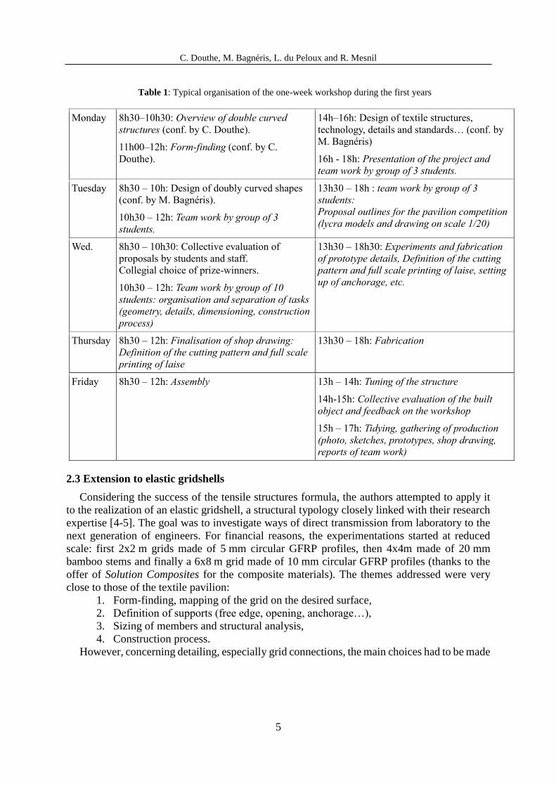
Table 1: Typical organisation of the one-week workshop during the first years
Monday 8h30–10h30: Overview of double curved
structures (conf. by C. Douthe).
11h00–12h: Form-finding (conf. by C.
Douthe).
14h–16h: Design of textile structures,
technology, details and standards… (conf. by
M. Bagnéris)
16h - 18h: Presentation of the project and
team work by group of 3 students.
Tuesday 8h30 – 10h: Design of doubly curved shapes
(conf. by M. Bagnéris).
10h30 – 12h: Team work by group of 3
students.
13h30 – 18h : team work by group of 3
students:
Proposal outlines for the pavilion competition
(lycra models and drawing on scale 1/20)
Wed. 8h30 – 10h30: Collective evaluation of
proposals by students and staff.
Collegial choice of prize-winners.
10h30 – 12h: Team work by group of 10
students: organisation and separation of tasks
(geometry, details, dimensioning, construction
process)
13h30 – 18h30: Experiments and fabrication
of prototype details, Definition of the cutting
pattern and full scale printing of laise, setting
up of anchorage, etc.
Thursday 8h30 – 12h: Finalisation of shop drawing:
Definition of the cutting pattern and full scale
printing of laise
13h30 – 18h: Fabrication
Friday 8h30 – 12h: Assembly 13h – 14h: Tuning of the structure
14h-15h: Collective evaluation of the built
object and feedback on the workshop
15h – 17h: Tidying, gathering of production
(photo, sketches, prototypes, shop drawing,
reports of team work)
2.3 Extension to elastic gridshells
Considering the success of the tensile structures formula, the authors attempted to apply it
to the realization of an elastic gridshell, a structural typology closely linked with their research
expertise [4-5]. The goal was to investigate ways of direct transmission from laboratory to the
next generation of engineers. For financial reasons, the experimentations started at reduced
scale: first 2x2 m grids made of 5 mm circular GFRP profiles, then 4x4m made of 20 mm
bamboo stems and finally a 6x8 m grid made of 10 mm circular GFRP profiles (thanks to the
offer of Solution Composites for the composite materials). The themes addressed were very
close to those of the textile pavilion:
1. Form-finding, mapping of the grid on the desired surface,
2. Definition of supports (free edge, opening, anchorage…),
3. Sizing of members and structural analysis,
4. Construction process.
However, concerning detailing, especially grid connections, the main choices had to be made
C. Douthe, M. Bagnéris, L. du Peloux and R. Mesnil
6
before the workshop, so that the consumables could be supplied on time. In comparison with
the tensile pavilion, an essential part of structural design could not be investigated by the
students. This is why the size of the prototype was progressively increased, trying to find a size
at which one will shift from mock-up to realistic detailing, with little success (the small size of
the grid members did not allow for knocked up details and most of the time pluming pipe
connectors were used) until 2016. It is worth mentioning here the “SheltAir pavilion” built by
G. Quinn et al in Berlin 2018 where very convincing details with similar circular composite
profiles were designed and will certainly inspire future editions of the workshops.
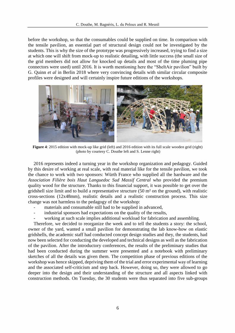
Figure 4: 2015 edition with mock-up like grid (left) and 2016 edition with its full scale wooden grid (right)
(photo by courtesy C. Douthe left and S. Lenne right)
2016 represents indeed a turning year in the workshop organization and pedagogy. Guided
by this desire of working at real scale, with real material like for the tensile pavilion, we took
the chance to work with two sponsors: Würth France who supplied all the hardware and the
Association Filière bois Haut Languedoc Sud Massif Central who provided the premium
quality wood for the structure. Thanks to this financial support, it was possible to get over the
gridshell size limit and to build a representative structure (50 m² on the ground), with realistic
cross-sections (12x48mm), realistic details and a realistic construction process. This size
change was not harmless to the pedagogy of the workshop:
- materials and consumable still had to be supplied in advanced,
- industrial sponsors had expectations on the quality of the results,
- working at such scale implies additional workload for fabrication and assembling.
Therefore, we decided to reorganize the week and to tell the students a story: the school,
owner of the yard, wanted a small pavilion for demonstrating the lab know-how on elastic
gridshells, the academic staff had conducted concept design studies and they, the students, had
now been selected for conducting the developed and technical designs as well as the fabrication
of the pavilion. After the introductory conferences, the results of the preliminary studies that
had been conducted during the summer were presented and a notebook with preliminary
sketches of all the details was given them. The competition phase of previous editions of the
workshop was hence skipped, depriving them of the trial and error experimental way of learning
and the associated self-criticism and step back. However, doing so, they were allowed to go
deeper into the design and their understanding of the structure and all aspects linked with
construction methods. On Tuesday, the 30 students were thus separated into five sub-groups
C. Douthe, M. Bagnéris, L. du Peloux and R. Mesnil
7
(each supervised by an academic) which had all the charge of some aspect of the final design
and had to experiment fabrication to be able then to systematize it:
- form and structure (definition of the final form and structural analysis)
- bracing (distribution over the structure and design of the tensioning system),
- foundation (design of anchorage, including slab characterization and setting-up),
- wooden grid (material characterization, framing, connection verification),
- covering (design and fabrication of covering casket system in PEHD)
Then on Wednesday, a general coordination meeting was organized before producing shop
drawings and launching fabrication. Thursday was dedicated to the assembling of the grid, then
Friday to the forming, bracing and covering.
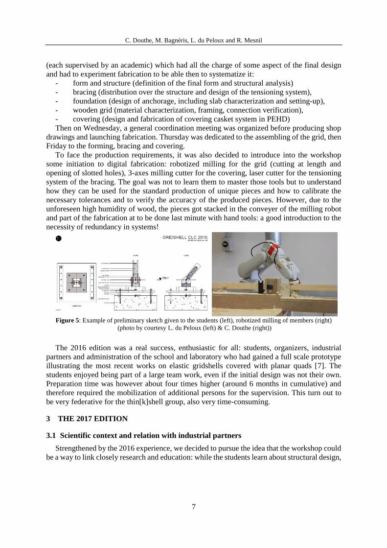
To face the production requirements, it was also decided to introduce into the workshop
some initiation to digital fabrication: robotized milling for the grid (cutting at length and
opening of slotted holes), 3-axes milling cutter for the covering, laser cutter for the tensioning
system of the bracing. The goal was not to learn them to master those tools but to understand
how they can be used for the standard production of unique pieces and how to calibrate the
necessary tolerances and to verify the accuracy of the produced pieces. However, due to the
unforeseen high humidity of wood, the pieces got stacked in the conveyer of the milling robot
and part of the fabrication at to be done last minute with hand tools: a good introduction to the
necessity of redundancy in systems!
Figure 5: Example of preliminary sketch given to the students (left), robotized milling of members (right)
(photo by courtesy L. du Peloux (left) & C. Douthe (right))
The 2016 edition was a real success, enthusiastic for all: students, organizers, industrial
partners and administration of the school and laboratory who had gained a full scale prototype
illustrating the most recent works on elastic gridshells covered with planar quads [7]. The
students enjoyed being part of a large team work, even if the initial design was not their own.
Preparation time was however about four times higher (around 6 months in cumulative) and
therefore required the mobilization of additional persons for the supervision. This turn out to
be very federative for the thin[k]shell group, also very time-consuming.
3 THE 2017 EDITION
3.1 Scientific context and relation with industrial partners
Strengthened by the 2016 experience, we decided to pursue the idea that the workshop could
be a way to link closely research and education: while the students learn about structural design,

C. Douthe, M. Bagnéris, L. du Peloux and R. Mesnil
8
they can also take part in the thoughts of the laboratory on the possibilities offered by digital
fabrication to the design of curved envelops. Indeed, in the last three years, considerable effort
has been made by the members of the thin[k]shell group to re-appropriate geometry and to
integrate the most recent developments of the new born field called “architectural geometry”
into practical tools for designers. The close collaboration with Prof. L. Hauswirth from the
UPEM helped a lot and has still extremely promising prospects, including the organization of
workshops for the mathematic students around applications to structural engineering. In parallel
to these theoretical developments, the Ecole des Ponts ParisTech invested in two robotic cells
for building a Co-Innovation Lab around digital fabrication applied to civil engineering. And
hence came naturally the idea that the workshop should illustrate the knowledge of the members
on advanced discrete geometry, structural design and robotic fabrication.
The 2017 pavilion is thus based on an original structural system, called shell-nexorade
hybrid, which derives from a surface initially meshed by planar quads which is transformed so
that members are only connected by pairs [8] (see figure 6). The pavilion hence tackles main
fabrication constraints of free form architecture: covering with quadrilateral panels, straight
members, simple T-joints for connection. To achieve this, an intricate game of eccentricities
between members (beam-beam and beam-panel) is necessary and realised by the machining by
collaborative 6-axes robots of the extremities and the top surfaces of the members.
Figure 6: Initial PQ-mesh (left), structure obtained by translation of the edges: the opposite edges of the quads
remain co-planar (middle), zoom on resulting eccentricities between members (right)
Industrial partners are really key to the project and were associated upstream of the design.
As a matter in fact, the authors believe that successful realisations of freeform structures require
a collaboration of all actors of the construction process: owner, designer and contractor, from
the beginning. All roles are here endorsed by the academic staff of the week, especially that of
the contractor which relies on a tailor made production process, but precisely this is where
industrial partners were indispensable:
- Simonin SAS, supplied the wood and served as consultant for wood machining,
- HAL Robotics, developed the software linking geometry to machine control command,
- ABB, set the robotic cell, helped calibrating the robots, guarantying process accuracy,
- Würth France, supplied hardware and served as consultant for connection design.
All partners attended the workshop and could explain their contribution to the pavilion
design and more generally their role into the design process of complex structures. For example,
for connections, a screw that goes beyond Eurocode 5 was used because it allows to transmit
normal forces along the grain of the wooden member. It was hence an opportunity to introduce
in the teaching the procedure of European Technical Agreement and the method for bringing
innovation in structural engineering practice.

C. Douthe, M. Bagnéris, L. du Peloux and R. Mesnil
9
3.2 Pedagogical objectives
Pedagogically, the principle remains the same: the academic staff (2 professors, 5 PhD
students and 3 technicians) does the concept and development designs while the students are in
charge of the technical design and fabrication/assembly of the pavilion. The week starts with
one day conferences about double curved structures, digital fabrication and the concept design
of the pavilion. On Tuesday and Wednesday, the students separate in sub-groups:
- geometry and structural analysis (interaction between form and forces)
- connection (experimental characterization of material and connection capacity,
verification of each connection),
- construction process and geometric control (3d photogrammetric reconstruction,
plumblines as well as triangulation with double decametres) design of anchorage
plates, including concrete slab characterization and setting-up),
- robotized manufacturing applied to wood machining (analysis of the production
process and fabrication of the last members and panels).
Each group is co-supervised by an academic and an external partner, which again allows for
experience sharing between students, researchers and private industries. Thursday and Friday
are then devoted to the assembly of the pavilion.
Contrary to the 2016 edition, no notebook with connection drawings is given to the students,
because the 2017 workflow is fully integrated numerically into the 3d modelling environment
of Rhinoceros/grasshopper. No shop drawings are produced or printed: the geometry being
completely three dimensional, it is directly transformed into machine commands for the robots
who mill the beams and bore inclined predrilling holes for screws (see figure 7). This
disappearing of drawing is not obvious, and we insisted all the week on the necessity to introdu-
ce geometric control procedure and on the difficulty linked with the interoperability of all the
numerical developments, which is another key issue for the successful realization of freeform
architecture.
Figure 7: [right] Workflow in the robotic cell: fixed feeder (1), stationary circular saw (2), milling (3-7), fixed
wood rooter (8). [left] First row: tool collision detection and second row: toolpath and robot simulation.
It must be noticed here that the ambition of building in one week a pavilion that should last
for one year and illustrate actual research developments goes beyond a one-week workshop.
Time spent for the pavilion was evaluated to approximately 18 months of a full time person,
without counting the time of the 32 students during the week. This is a fantastic adventure that
truly united the research group and helped progressing technically all the involved PhD

C. Douthe, M. Bagnéris, L. du Peloux and R. Mesnil
10
students. Students were immersed in an enthusiastic framework and never complained being
only a wheel of a complex organization. As a matter in fact, one month after the completion of
the workshop, the school celebrated the 20 years of its settlement on the campus and the students
of the workshop were the only ones who had the chance to present their work in pecha-kucha
plenary session, which they have done brilliantly.
4 CONCLUSIONS
We presented here a feedback on a design/build workshop lead over the last nine years. This
workshop is about structural design with application to doubly curved structures. It aims at
experimenting the necessary compromise between form, forces, structure, material and
technology in the design process. We insisted on the interest of working at full scale, with the
real material (or at least realistic material) for the relevance of the work on detailing and
construction process. We explored various situation scenarios to make the students familiar
with the various phases from design to fabrication.
Figure 7: Photo of participants (staff, partners on side, students in the middle) in front of the 2017 pavilion.
REFERENCES
[1] Vrontissi M, Architectural Design Methodology informing Structural Design, PhD thesis
ETHZ 2018
[2] Adria M et al, Talca: Matter of education, Arquine, Mexico City, 2013. 208 pp.
[3] Kawaguchi M, Plenary lecture, Symposium of IASS 2004, From Models to realization.
[4] Caron JF et al, Gridshells in composite materials: Construction of a 300 m² Forum for the
Solidays' Festival in Paris, Struct. Eng. Int., 2013 22 (3), 408-414
[5] Du Peloux L. et al, Construction of a large composite gridshell structure: a lightweight
structure made with pultruded GFRP tubes, Struct. Eng. Int 26 (2), 160-167
[6] Bagnéris M. et al, Structural morphology issues in free form design , International Journal
of Space Structures, Vol. 23, n°2, pp. 79-87, 2008.
[7] Douthe C. et al, Isoradial meshes: covering elastic gridshells with planar facets,
Automation in Construction (2017), 83 pp 222-236
[8] Mesnil R. et al Form-finding of reciprocal frames with the method of translations.
Automation in Construction, accepted 2018.