building permit required -...
TRANSCRIPT

1-8 ON-SITE SEWAGE SYSTEMS 2012 © QUEEN’S PRINTER FOR ONTARIO 2013
MODULE 1 INITIAL SCREENING AND BACKGROUND
INSTRUCTIONSRead Steps 1 and 2; complete the questions at the end of Step 2; then do the group activity. Do not go past STOP.
BUILDING PERMIT REQUIREDBefore any installation, extension or alteration of material or material repair of a sewage system can take place, a building permit must be obtained from the principal authority (local authority or the municipality, board of health or conservation authority under agreement with the local municipality or the board of health or conservation authority listed in Division C Table 1.7.1.1.) in the municipalities and the territory without municipal organization of the Districts of Northern Ontario before any installation, extension, or alteration of material or material repair of a sewage system can take place. Permit applications are typically associated with the construction of a new sewage system or the replacement of an existing system. A building permit is also required to conduct an upgrade, repair, or a material alteration of an existing sewage system.
According to Subsection 8(1) of the Building Code Act, no person shall construct or demolish a sewage system without a building permit. Division C, Article 1.3.1.2., states that the owner of the property or the authorized agent may apply for a building permit. They are obliged to make sure that the necessary permits are obtained prior to starting any work. The permit application process provides the inspector with a description of the proposed installation, existing lot and soil conditions, and ensures that the sewage system conforms to Provincial regulations. It also allows the inspector to review the adequacy of the design.
INFORMATION REQUIREDThe principal authority provides a permit application package to the property owner. Installers and inspectors should be familiar with the requirements of the application. The application for a building permit should be submitted by a person specified in the Code and using the prescribed form in the regulation. A complete application will typically include
• the name, address, and telephone number of the owner of the property
Step 1 Permit RequirementsKnowing when a permit is required, and how to submit an application for a building permit.
Step 2 Submission of an ApplicationKnowing what information is required for completion of the application.,

© QUEEN’S PRINTER FOR ONTARIO 2013 ON-SITE SEWAGE SYSTEMS 2012 1-9
MODULE 1 INITIAL SCREENING AND BACKGROUND
1
• the name, address, telephone number, and Building Code Identification license number (BCIN) of the person installing the sewage system
• a site evaluation report – Article 8.2.1.2.
The property owner or agent must sign the completed application. The inspector may require additional information such as a soil percolation test, a soil classification analysis or the excavation of test pits.

1-20 ON-SITE SEWAGE SYSTEMS 2012 © QUEEN’S PRINTER FOR ONTARIO 2013
MODULE 1 INITIAL SCREENING AND BACKGROUND
to settle to the bottom, and the lighter oils and greases rise to the top (Figure 1.4.7).
Baffle or T-ConnectionBaffle or T-Connection
SanitarySewer
Effluent
FIGURE 1.4.7 TYPICAL SEPTIC TANK
Bacteria in the septic tank decompose or liquefy some of the solid matter retained in the tank. The effluent passes from the tank to the leaching bed, and into the underlying soil where the final treatment occurs.
The receiving soil is the most important component of the septic system. It is the primary means by which the effluent is treated, and helps to minimize contamination of the groundwater. Once the effluent passes into the soil, the remaining nutrients are removed by bacterial action, and any remaining solids and microorganisms are filtered through a combination of physical, chemical, and biological reactions within the soil mass. For example, some of the nutrients may be used by vegetation, such as grasses; some may become fixed to soil particles; and other nutrients, percolating down towards the water table, are gradually diluted to acceptable levels. For treatment in soil to occur, the effluent must pass through unsaturated soils. Therefore, it is very important that there be a sufficiently thick layer of unsaturated soil above the high groundwater table (Figure 1.4.8).

© QUEEN’S PRINTER FOR ONTARIO 2013 ON-SITE SEWAGE SYSTEMS 2012 1-21
MODULE 1 INITIAL SCREENING AND BACKGROUND
1
FIGURE 1.4.8 THE TREATMENT OF SEWAGE BY THE SOIL
DESIGN PARAMETERS AFFECTING A CLASS 4 SYSTEM DESIGNThe design criteria for Class 4 sewage systems are detailed in Sections 8.6 and 8.7 of the Building Code. The basic design of a Class 4 sewage system depends on the estimated flow (volume of sanitary sewage) from a building, the soil permeability (ability of the soil to accept the effluent) and the effluent quality. The flow volume estimate, called the total daily design sanitary sewage flow, takes into account several factors, such as
• the type and size of building or residential occupancy
• the number of bedrooms and fixture units
• the amount of sanitary sewage generated by the occupants of the building (residents, employees, patrons, etc.)
The characteristics of the receiving soil determines its ability to receive the applied effluent. The quality of the effluent applied to the soil (septic tank or other treatment unit’s effluent) would affect the size of the leaching bed.
Step 2 Design CriteriaKnowing the criteria contained in the Code that affect the design of on-site Class 4 sewage systems.
1-22 ON-SITE SEWAGE SYSTEMS 2012 © QUEEN’S PRINTER FOR ONTARIO 2013
MODULE 1 INITIAL SCREENING AND BACKGROUND
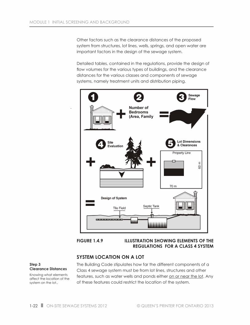
Other factors such as the clearance distances of the proposed system from structures, lot lines, wells, springs, and open water are important factors in the design of the sewage system.
Detailed tables, contained in the regulations, provide the design of flow volumes for the various types of buildings, and the clearance distances for the various classes and components of sewage systems, namely treatment units and distribution piping.
Number ofBedrooms(Area, Family
FIGURE 1.4.9 ILLUSTRATION SHOWING ELEMENTS OF THE REGULATIONS FOR A CLASS 4 SYSTEM
SYSTEM LOCATION ON A LOTThe Building Code stipulates how far the different components of a Class 4 sewage system must be from lot lines, structures and other features, such as water wells and ponds either on or near the lot. Any of these features could restrict the location of the system.
Step 3 Clearance DistancesKnowing what elements affect the location of the system on the lot.,

© QUEEN’S PRINTER FOR ONTARIO 2013 ON-SITE SEWAGE SYSTEMS 2012 1-23
MODULE 1 INITIAL SCREENING AND BACKGROUND
1
These clearance distances are described in more detail in Modules 2 and 5.
QUESTIONSComplete the questions below.
1. Name the two main components of a Class 4 sewage system and state their functions.
receives the final treatment.
2. Which of the following occurs in the septic tank?
a) Oils and grease float to the top, forming a scum layer.
b) Solids settle at the bottom forming the sludge.
c) Solids and liquids are separated.
d) All of the above.
3. Explain how the effluent is further treated after it moves out of the septic tank, through the leaching bed, and into the soil.
4. What are the two most important things that affect the design of a Class 4 sanitary sewage system?
GroupCompare your answer with your group. Write the group answers on the flipchart. Be prepared to discuss your group results with the rest of the class.
STOP
INSTRUCTIONSRead Steps 4 and 5 of Learning Task 1.4, following; complete the questions at the end of Step 5; and then do the group activity. Proceed only to the STOP indicator.
SIZING THE SEPTIC TANKThe minimum size of a septic tank required depends on the total daily design sanitary sewage flow. According to OBC Sentence 8.2.2.3.(1) , the minimum working capacity of a septic tank cannot be less than twice the total daily design sanitary sewage flow for residential occupancies, three times for non-residential occupancies, and not less than 3 600 L.
Step 4 The Septic TankKnowing the regulations and other elements that determine tank size and connection of multiple tanks.
•

1-24 ON-SITE SEWAGE SYSTEMS 2012 © QUEEN’S PRINTER FOR ONTARIO 2013
MODULE 1 INITIAL SCREENING AND BACKGROUND
The septic tank is composed of at least two compartments. The size of the first compartment must be at least 1.3 times the total daily design sanitary sewage flow, and not less than 2,400 L. The size of the second compartment must be at least 50% of the first compartment [Sentence 8.2.2.3.(3)]. In addition, the tank should be sized to handle peak sanitary sewage discharges that may occur from time to time during periods of heavy use.
Occasionally, the installation of multiple septic tanks may be necessary to handle estimated high flow volumes. Where several tanks are used, they are connected in series. In accordance with the regulations, the first tank must have a working capacity equal to 1.3 times the total daily design sanitary sewage flow or 3,600 Litres as explained by Clause 8.2.2.3.(4)(a) and the second and each subsequent tank shall have a working capacity equal to at least 50% of the first tank, as provided by Clause 8.2.2.3.(4)(b) of the regulations. According to Sentence 8.2.2.2.(1), a tank used as a treatment unit in a Class 4 sewage system must conform to the requirements of CSA-B66, “Design, Material and Manufacturing Requirements for Prefabricated Septic Tanks and Sewage Holding Tanks”. The referenced standard provides design criteria for liquid level drops between compartments, for partitions within the tank and for tank connections and piping. The criteria are intended to ensure the structural integrity of septic tanks, and to aid movement of sanitary sewage to the outlet.
TYPES OF LEACHING BEDSThe next component of the sewage system is the leaching bed which is the most important component of a Class 4 sewage system. In the leaching bed effluent is treated to become an acceptable liquid before it reaches the high ground water table.
A conventional in-ground leaching bed is a system of absorption trenches and distribution pipes set in a layer of stone within the native soil into which effluent from the septic tank is distributed.
Conventional in-ground leaching beds are normally installed where• the high ground water table or bedrock is not close to the
ground surface, and
• the percolation rate of the soil ranges between 1 and 50 min/cm (Figure 1.4.10).
Step 5 Leaching Bed TypesKnowing the different types of leaching beds.

© QUEEN’S PRINTER FOR ONTARIO 2013 ON-SITE SEWAGE SYSTEMS 2012 2-5
MODULE 2 SITE EVALUATION
2
FIGURE 2.1.2 THE IMPORTANCE OF DRAINAGE
To ensure that the regulations are met, you should assess the following, using your visual observations and judgment to estimate
• site grades—to evaluate the possible need for grading or importation of leaching bed fill for the construction
• the presence of drainage swales and the direction of overland flow—to ensure that the final design will divert surface runoff away from the leaching bed
• a slope greater than one vertical unit to 10 horizontal units (a 10% grade)—to determine if the lot would require excessive grading. It may be un economical to construct a standard leaching bed on such a lot, even though the regulations stipulate that a leaching bed may be built on slopes of a grade up to 25% (four horizontal units to one vertical unit), except for Type B dispersal where the slope must not exceed 15%.

2-46 ON-SITE SEWAGE SYSTEMS 2012 © QUEEN’S PRINTER FOR ONTARIO 2013
MODULE 2 SITE EVALUATION
Fine-Grained (more than 50% passing a #200 sieve)
ML Inorganic silts and very fine sands, rock flour, silty or clayey fine sands, clayey silts with slight plasticity
10–5–10–6 20–50 Medium to low permeability
CL Inorganic clays of low-to-medium plasticity, gravelly clays, sandy clays, silty clays, lean clays
≤10–6 >50 Unacceptable
OL Organic silts, organic silty clays of low plasticity; liquid limit less than 50
≤10–5 20–50 Acceptable, if clay content low enough
MH Inorganic silts, micaceous or diatomaceous fine sandy or silty soils, elastic silts
≤10–6 >50 Unacceptable
CH Inorganic clays of medium-to-high plasticity; organic silts
≤10–7 >50 Unacceptable
OH Organic clays of medium-to-high plasticity; organic silts; liquid limit over 50
≤10–6 >50 Unacceptable
QUESTIONSComplete the questions below. Provide the Code references where appropriate.
1. If you do not use a percolation test to estimate the T-time, what would you use?

© QUEEN’S PRINTER FOR ONTARIO 2013 ON-SITE SEWAGE SYSTEMS 2012 2-51
MODULE 2 SITE EVALUATION
2
1. Figure 2.3.4. illustrates four types of Class 4 leaching beds. For each illustration, identify the Ontario Building Code Subsection(s) that govern the respective construction.
a) in-ground absorption trenches
b) raised (filled based) absorption trenches and mantle
c) raised filter bed
d) shallow buried (pressurized system) trenches
2. If the T-time in the soil underlying the proposed leaching bed is 55 minutes per centimeter, which of the following can you do? (Daily design sanitary sewage flow exceeds 1,000 L/day)
a) consider the design of a conventional leaching bed
b) consider the design of a raised leaching bed, (absorption trench or filter bed)
c) consider the use of shallow buried trenches
3. Name a site condition that prohibits the installation of an in-ground leaching bed.
4. What is the only system that may be constructed in soils with T time that exceeds 50 min/cm?
Group
Compare your answers with those of others in your group. Write the group answers on the flipchart. Be prepared to discuss your group results with the rest of the class.
STOP

2-52 ON-SITE SEWAGE SYSTEMS 2012 © QUEEN’S PRINTER FOR ONTARIO 2013
MODULE 2 SITE EVALUATION
LEARNING TASK 2.4 FINAL ASSESSMENT OF SITE EVALUATION
Knowing what decisions must be made based on a review of all the information collected from the site evaluation.
INSTRUCTIONSRead Step 1; answer the question at the end of Step 1; then do the group activity.Based on a complete site evaluation, you should be able to answer the following questions:
• Which class of system (1 through 5) is suitable for the lot?
• Are there any problems with lot size, soil type, or clearance requirements that may prohibit the construction of the sewage system?
• What is the most appropriate system that can be installed? A standard in-ground leaching, a raised bed, a filter bed, a shallow buried trench (pressurized) bed, or a dispersal bed?
For example, if the soils are estimated to have a T-time greater than 50 min/cm, or if bedrock or the high ground water table is within 900 mm of the bottom of the absorption trench, the site will probably require a raised leaching bed. In the case of a raised bed, the minimum clearance distances from distribution piping must be increased by twice the height that the leaching bed was raised above the original ground. Sentences 8.2.1.6.(2) and 8.7.4.2.(11). If the percolation time is between 1 and 50 min/cm, then a traditional in-ground leaching bed may be considered.
Based on your findings, are you satisfied that there is sufficient room to accommodate the proposed design for an on-site sanitary sewage system on the lot?
QUESTIONAnswer the question below.
1. What is the importance of the final assessment of the site evaluation?

5.1
ON-SITE SEWAGE SYSTEMS 2012
MODULE 5.1
CLASS 4 SEWAGE SYSTEMSModule time: 7 hours and 15 minutes

© QUEEN’S PRINTER FOR ONTARIO 2013 ON-SITE SEWAGE SYSTEMS 2012 5.1-13
MODULE 5.1 CLASS 4 SEWAGE SYSTEMS
5.1
INSTRUCTIONSRead Step 4 of Learning Task 5.2, following; complete the questions at the end of Step 4; then do the group activity.
As you learned in Learning Task 5.1, Step 1, there are two pre-treatment systems:
• septic tank
• Other treatment units
• Level II treatment unit
• Level III treatment unit
• Level IV treatment unit
Maximum permitted effluent concentrations are different for each of these levels. They are detailed in Subsection 8.6.2., “Treatment Units”.
The effluent filter must be either an integral part of the outlet device or contained within a separate tank or compartment, which may also be an integral part of the septic tank structure. Effluent filters must be sized to filter particles of 1.6 mm, have a minimum flow area of 550 cm2 and be installed in accordance with the manufacturer’s recommendation [Sentences 8.6.2.1.(1) and (2)].
The treatment unit, other than a septic tank, shall be designed such that the effluent does not exceed the contaminants’ levels in Columns 2 and 3 of Table 8.6.2.2.: [Sentence 8.6.2.2.(1)].
Step 4 Effluent CharacteristicsKnowing the acceptable concentration levels for effluent from different treatment systems.

5.1-14 ON-SITE SEWAGE SYSTEMS 2012 © QUEEN’S PRINTER FOR ONTARIO 2013
MODULE 5.1 CLASS 4 SEWAGE SYSTEMS
Table 8.6.2.2. Other Treatment Unit Effluent Quality Criteria
Forming Part of Sentences 8.6.2.2.(1) and (2)
Item Column 1 Column 2 Column 3Classification of Treatment Unit(1)
Suspended Solids(2)
CBOD5(2)
1. Level II 30 25
2. Level III 15 15
3. Level IV 10 10
Note to Table 8.6.2.2.:(1) The classifications of treatment units specified in Column 1 correspond
to the levels of treatment described in CAN/BNQ 3680-600, “Onsite
Residential Wastewater Treatment Technologies”.(2) Maximum concentration in mg/L based on a 30 day average.
A treatment unit that is used in conjunction with a leaching bed constructed as a shallow buried trench, Type A dispersal bed or Type B dispersal bed must be designed such that the effluent does not exceed the maximum concentrations set out opposite a Level IV treatment unit in Columns 2 and 3 of Table 8.6.2.2. [Sentences 8.6.2.2.(2)].
BOD5 is the five-day biochemical oxygen demand and CBOD5 is the five-day carbonaceous biochemical oxygen demand.
All treatment units, other than septic tanks, must permit sampling of the effluent [Sentence 8.6.2.2.(4)].
QUESTIONSComplete the following questions.
1. Will the effluent coming from a septic tank and a septic tank with a filter be of the same quality or of a different quality? Give a reason for your answer.
the retention of more solids in the septic tank, thus it will be clearer than effluent from a septic tank without an effluent filterIn what units are maximum effluent concentrations measured?
© QUEEN’S PRINTER FOR ONTARIO 2013 ON-SITE SEWAGE SYSTEMS 2012 5.1-15
MODULE 5.1 CLASS 4 SEWAGE SYSTEMS
5.1
2. What should you know about CBOD5, and suspended solids?
3. How should septic tank filters be sized and installed?
GroupCompare answers within your group. Write the group answers on the flipchart. Be prepared to discuss your group results with the rest of the class.
STOP
LEARNING TASK 5.3 GENERAL INFORMATION ON LEACHING BEDS
Knowing the treatment and sub-surface adsorption capabilities of the different types of Class 4 leaching bed systems.
INSTRUCTIONSRead Step 1; complete the questions at the end of Step 1; then do the group activity.
The leaching bed is a critical part of the Class 4 sewage system. The performance of the leaching bed is measured by its ability to perform the following functions:
• the treatment of effluent in the soil, and
• the absorption of the treated effluent by the underlying and surrounding soils without it breaking to surface.
The application of effluent to a soil surface over a long period of time results in the formation of a biomat at the soil/effluent interface. Bacteria in the biomat feed on the organic matter in the effluent. Therefore, biomat plays an important role in the treatment process. Treatment of the effluent also takes place in the soil layer underneath the biomat as it percolates downward and is exposed to bacterial action in the soil pores (voids). This process must permit sufficient time for effluent to be in contact with soil particles in order to achieve an acceptable level of treatment to occur before effluent reaches groundwater. Inground absorption trench leaching bed could be installed only when the percolation time of the soil is between 1 min/cm and 50 min/cm, as required by Clause 8.7.2.1.(1)(b), unless the leaching bed system is a shallow buried trench where T-time of the soil could be as high as 125 min/cm. The clearance
Step 1 Treatment of Sanitary SewageKnowing what affects the operation of a leaching bed.

5.1-16 ON-SITE SEWAGE SYSTEMS 2012 © QUEEN’S PRINTER FOR ONTARIO 2013
MODULE 5.1 CLASS 4 SEWAGE SYSTEMS
distances stipulated in Article 8.2.1.6. include allowances for the necessary treatment to take place [Article 8.2.1.6.].
QUESTIONSComplete the following questions.
1. What happens in the biomass layer?
2. Where is the biomat formed?
3. What happens to the effluent when it percolates down into the soil?
takes place where aerobic bacteria feed on the contaminants in the effluent providing the final treatment of the effluent.
4. Why are clearance and minimum distances important in this treatment?
be in contact with soil particles so adequate treatment can take place before effluent reaches water sources
5. What type of bacteria in soil feed on the contaminant in the effluent, and what do they need to perform this function?
Aerobic bacteria feeds on the contaminants in the effluent and need oxygen to survive.Group
Compare answers within your group. Write the group answers on the flipchart. Be prepared to discuss your group results with the rest of the class.
STOP

© QUEEN’S PRINTER FOR ONTARIO 2013 ON-SITE SEWAGE SYSTEMS 2012 5.1-17
MODULE 5.1 CLASS 4 SEWAGE SYSTEMS
5.1
INSTRUCTIONSRead Step 2 of Learning Task 5.3, following; complete the questions at the end of Step 2; then do the group activity.
INSPECTION CONSIDERATIONSThere are several important considerations to be aware of, when you are inspecting or evaluating a proposed leaching bed site [Article 8.7.2.1.]:
1. The area must be sufficient for the soil to absorb effluent on a continuing basis without clogging at the soil–effluent interface.
2. The area of the soil surface is related to the daily design sanitary sewage flow, the percolation time of the soil, and the effluent quality. Effluent must be applied as evenly as possible over the entire soil surface. Article 8.7.3.1. stipulates the required length of distribution piping according to the sanitary sewage flow and the percolation time of the soil.
3. Effluent usually passes too quickly through coarse-grained soils to receive adequate treatment. A minimum percola tion time of 1 min/cm is stipulated in Clause 8.7.2.1.(1)(b). Where natural soils are coarse-grained, it may be necessary to add finer-grained soil to the leaching bed, to increase the percolation time. It may also be necessary to increase clearance distances from the Code minimum, especially when dealing with shoreline properties on sensitive lakes [Sentence 8.2.1.4.(2)].
4. In fine-grained soils, percolation of effluent is slow. Once these soils are saturated, they do not drain readily. Replenishment of oxygen in the treatment area is slowed, and treatment is either slowed, or stops altogether. The maximum percolation time for a soil to be used for an in-ground absorption trench system is 50 min/cm, as stipulated in the Code. For shallow buried trench systems, the T-time is increased to 125 minutes [Clause 8.7.2.1.(1)(b)].
Step 2 Inspecting and Evaluating the Leaching Bed SiteKnowing what to look for, when inspecting or evaluating the site of a proposed leaching bed.

5.1-18 ON-SITE SEWAGE SYSTEMS 2012 © QUEEN’S PRINTER FOR ONTARIO 2013
MODULE 5.1 CLASS 4 SEWAGE SYSTEMS
5. The most suitable soil for a leaching bed should possess the advantages of both fine-grained and coarse-grained soils, and have none of the disadvantages. The advantage of fine-grained soils is their high degree of effluent treatment. However, their disadvantage is their very low permeability, which prevents the effluent from actually moving through the soil mass. On the other hand, effluent can move quite freely through very coarse-grained soils; however, their treatment performance is very poor. A leaching bed with a percolation time between 10 and 20 min/cm usually represents ideal conditions.
6. Leaching beds cannot be placed in or on an area that is subject to flooding and that may be expected to cause damage to or to impair the operation of the bed.
7. Leaching beds are not permitted in an area where the average slope exceeds one unit vertically to four units horizontally except for Type B dispersal beds where the maximum allowable slope is one unit vertically to seven units horizontally.
QUESTIONSComplete the following questions.
1. How do the soil characteristics affect the area of the leaching bed?
2. How might you slow down the percolation time in coarse-grained soils?
3. Why are fine-grained soils not necessarily good soils for the construction of leaching beds?
4. What percolation time will provide the best treatment of sewage in the soil?
GroupCompare answers within your group. Write the group answers on the flipchart. Be prepared to discuss your group results with the rest of the class.
STOP
INSTRUCTIONSRead Step 3 of Learning Task 5.3, following; complete the questions at the end of Step 3; then do the group activity.

© QUEEN’S PRINTER FOR ONTARIO 2013 ON-SITE SEWAGE SYSTEMS 2012 5.1-19
MODULE 5.1 CLASS 4 SEWAGE SYSTEMS
5.1
Continued acceptance of effluent by the underlying soil is vital to the continued functioning of a leaching bed. If the input of effluent into the soil exceeds its capacity to receive and transmit the effluent, mushy ground or surface breakout of sanitary sewage will occur. This is a common cause of failure in sewage systems, especially in large systems where the problem increases in proportion to increasing daily sanitary sewage flow.74 Therefore, it is very important to follow regulations about sanitary sewage flow designs, percolation times, and clearance distances.
When the percolating effluent reaches the level of the water table, bedrock, or impermeable soil, the sanitary sewage will mound on top of this level. (Refer to Module 2, Learning Task 2.2, Step 5, and Figure 2.2.8). Mounding will continue until sufficient pressure is reached to force a downward or lateral (sideways) movement. The greater the resistance of the underlying soil to this move ment, the greater the portion of the liquid that will move laterally, forming a plume (refer to Module 2, Learning Task 2.2, Step 6, and Figure 2.2.10). In addition, the greater the resistance to movement, the higher the sanitary sewage will mound toward the surface. If it mounds to a level that will flood the soil–sewage interface, it will remove the oxygen from the soil and inhibit the natural treatment of the sewage. In extreme cases, it can cause a backup of the sanitary sewage system, and could result in surface breakout of the effluent.
The capacity of the leaching bed to safely receive and transmit the applied effluent, without mounding or breakout, is one of the major factors in the design of either a single leaching bed, or a concentration of separate leaching beds in any one given area, such as in a housing subdivision.
In summary, the following are the major steps in the treatment of sanitary sewage by a properly designed on-site Class 4 sewage system.
1. Sanitary sewage enters the septic tank, where treatment begins. In general, the tanks are designed to retain the sewage for 48 hours, to allow solids to settle and treatment to take place.
2. The sanitary sewage exits the tank as effluent. In some cases, this effluent is given additional treatment by a treatment unit which lowers the suspended solids and CBOD5 in the effluent.
Step 3 Subsurface Absorption of EffluentKnowing what affects the capacity of a leaching bed.
5.1-20 ON-SITE SEWAGE SYSTEMS 2012 © QUEEN’S PRINTER FOR ONTARIO 2013
MODULE 5.1 CLASS 4 SEWAGE SYSTEMS
3. Level II, III or IV treatment units are required if the effluent is to be discharged to a filter bed when the total daily design sanitary sewage flow exceeds 5 000 L, and a Level IV treatment unit is required if the effluent is directed to a shallow buried trench system and Type A or Type B dispersal beds. [Sentences 8.7.5.1.(1) and 8.6.2.2.(2)].
4. Once the effluent enters the absorption trenches, it percolates down through soil which must be unsaturated for the treatment to take place.
5. If there is at least 900 mm of unsaturated soil above the high ground water table, the bacteria in the voids of the soil mass will treat the effluent and make it safe to be discharged to the ground water without causing contamination.
6. Impairment and contamination of the environment are possible if:
• the treatment tanks are not properly designed
• the treatment tanks malfunction
• the leaching bed is not properly designed or constructed
• the leaching bed malfunctions
• minimum clearance distances are not maintained
• minimum vertical separation above the high groundwater table, bedrock, or clay soils are not met
7. In summary, sanitary sewage passes through:
• treatment tanks where the sanitary sewage becomes effluent
• a leaching bed where the effluent is transported into the soil
• the unsaturated subsoil where the effluent is naturally treated to levels acceptable for introduction into the environment.
8. From sanitary sewage → effluent → acceptable liquid.
QUESTIONSComplete the following questions.
1. What does mushy ground or surface breakout of sewage tell you about the leaching bed? What might cause these conditions?

© QUEEN’S PRINTER FOR ONTARIO 2013 ON-SITE SEWAGE SYSTEMS 2012 5.1-21
MODULE 5.1 CLASS 4 SEWAGE SYSTEMS
5.1
2. Mounding of the groundwater table beneath a leaching bed may cause
a) the effluent from the leaching bed reaches the groundwater without adequate treatment
b) an increase in the natural treatment by allowing the effluent to be mixed with water, thus diluting the sanitary sewage impact on the groundwater
c) the effluent to move laterally instead of downward
d) flooding of the soil/ effluent interface, thus removing oxygen from the soil and inhibiting natural treatment
GroupCompare answers within your group. Write the group answers on the flipchart. Be prepared to discuss your group results with the rest of the class.
STOP
LEARNING TASK 5.4 DISTRIBUTION OF EFFLUENT TO THE LEACHING BED
Knowing the different types of distribution systems and how they work.
INSTRUCTIONSRead Steps 1 and 2; complete the questions at the end of Step 2; then do the group activity.
Effluent from a septic tank or other treatment unit flows from the distribution system into the leaching bed. The purpose of the distribution system is to evenly distribute the effluent throughout the leaching bed area. Components of the system may include
• the piping that connects the septic tank to either a distribution box or a header, and from the distribution system to each of the individual distribution pipes
• a pumping system to dose the leaching bed
• distribution boxes or headers to split the flow to segments of the leaching bed or directly to each line of the distribution pipe
• the lines of distribution pipes
There are three main types of distribution systems:
Step 1 Distribution SystemKnowing the components of a distribution system.
Step 2 Gravity, Dosed, and Pressurized SystemsKnowing how the different sanitary sewage distribution systems work.

5.1-22 ON-SITE SEWAGE SYSTEMS 2012 © QUEEN’S PRINTER FOR ONTARIO 2013
MODULE 5.1 CLASS 4 SEWAGE SYSTEMS
• gravity flow
• dosed
• pressurized
GRAVITY FLOW DISTRIBUTION SYSTEMThe gravity flow distribution system is the most common method of effluent distribution. The effluent is pushed from the tank by hydraulic displacement, and then trickles by gravitational pull from the septic tank to the individual distribution pipes. Usually, the treatment tank is a flow-through design that displaces, to the leaching bed, a volume of effluent equal to the volume of sanitary sewage flowing into the tank. Effluent flows by gravity from the tank to the leaching bed. You will learn about some of the requirements concerning distribution pipes later in this Module.
DOSED DISTRIBUTION SYSTEMA dosed distribution system is required when the total length of the distribution pipe required is 150 m or more. A pump or a siphon is used to send a specified volume of effluent to the leaching bed in a single dose. Article 8.6.1.3. of the Code stipulates the regulations regarding the use of pumps and siphons.
With this type of system, either the pumping chamber or the siphon tank is usually located immediately down gradient of the treatment unit, and generally receives gravity flow from the treatment system. The regulations state that the siphon or pump tank may be a separate compartment within the tank structure [Sentence 8.6.1.3.(1)].
Within a 15-minute time frame, the pump or siphon periodically conveys a measured amount of effluent under pressure from the treatment unit to the distribution lines [Sentence 8.6.1.3.(4)]. The distribution lines themselves are not usually under pressure; the effluent flows through them by gravity. The effluent is forced (dosed) into the distribution pipes at a rate equal to 75% of the lines’ total volume. This periodic dosing of the leaching bed provides a more even distribution of the effluent over the entire bed area than the gravity discharge. It also allows the bed to drain between doses, promoting strong bacterial action in the biomat. Care should be taken to avoid freezing of the distribution lines in the winter.

© QUEEN’S PRINTER FOR ONTARIO 2013 ON-SITE SEWAGE SYSTEMS 2012 5.1-23
MODULE 5.1 CLASS 4 SEWAGE SYSTEMS
5.1
PRESSURIZED DISTRIBUTION SYSTEMSA shallow buried trench system and Type B dispersal bed are pressurized distribution systems. In these systems, a minimal pressure is maintained at the terminal end of all the lines of distribution pipe. These systems should be professionally designed, and maintained.
QUESTIONSComplete the following questions.
1. What are the distribution system components of a Class 4 System, and what are their purpose?
2. Explain how effluent reaches the leaching bed in a gravity flow system.
3. What is a dosed system? When is it required?
4. What is the purpose of dosing?
GroupCompare answers within your group. Write the group answers on the flipchart. Be prepared to discuss your group results with the rest of the class.
STOP
INSTRUCTIONSRead Step 3 of Learning Task 5.4, following; complete the questions at the end of Step 3; then do the group activity.

5.1-28 ON-SITE SEWAGE SYSTEMS 2012 © QUEEN’S PRINTER FOR ONTARIO 2013
MODULE 5.1 CLASS 4 SEWAGE SYSTEMS
The regulation goes on to state that:• a leaching bed shall not be covered with any material
having a hydraulic conductivity of less than 0.01 m/day [Sentence 8.7.2.1.(2)].
Hydraulic conductivity is a measure of the permeability of the soil. The covering material should be permeable to ensure some percolation from the ground surface, and evaporation through the leaching bed.
Article 8.7.2.1. of the Building Code further stipulates that:• the surface of the leaching bed shall be shaped to shed
water, and together with the side slopes of any raised portion, shall be protected against erosion in such a manner as to not inhibit the evaporation and transpiration of waters from the soil or leaching bed fill, and to not cause plugging of the distribution pipes [Sentence 8.7.2.1.(3)].
• no part of a leaching bed shall be sloped steeper than 1 unit vertically to 4 units horizontally [Sentence 8.7.2.1.(4)].
• the leaching bed shall be designed to be protected from compaction or any stress or pressure that may result in the impairment or destruction of any pipe in the leaching bed, or that may result in the smearing of the soil or leaching bed fill [Sentence 8.7.2.1.(5)].
QUESTIONSComplete the following questions.
1. What is the range of percolation time allowed for a shallow buried trench system?
2. Why do you think that the regulations stipulate that hydraulic conductivity of the covering material must not be less than 0.01 m/day?
3. During construction, how do you prevent the distribution pipes from settling?

© QUEEN’S PRINTER FOR ONTARIO 2013 ON-SITE SEWAGE SYSTEMS 2012 5.1-29
MODULE 5.1 CLASS 4 SEWAGE SYSTEMS
5.1
4. A leaching bed may be placed in an area subject to flooding
a) if the area is only flooded once every 25 years
b) if banks of soil are placed around the leaching bed to protect it from flood waters
c) if flooding is not expected to cause damage to the leaching bed that would result in the impairment of its operations
d) a leaching bed may never be placed in an area subject to flooding
GroupCompare answers within your group. Write the group answers on the flipchart. Be prepared to discuss your group results with the rest of the class.
STOP
LEARNING TASK 5.6 CONSTRUCTION OF THE ABSORPTION TRENCH
Knowing the Code requirements that affect construction of an absorption trench.
INSTRUCTIONSRead Steps 1 and 2; complete the questions at the end of Step 2; then do the group activity.
The length of the distribution pipe is based on two parameters that have already been discussed in Modules 2 and 3. These parameters are the total daily design sanitary sewage flow (Q) and the percolation time (T) and is affected by the quality of the effluent.
Q is obtained from Tables 8.2.1.3.A and 8.2.1.3.B. T is obtained from either an estimation of the percolation time from the grain size analysis or from the on-site percolation tests referred to in Sentence 8.2.1.2.(2) of the Code.
The total length of the distribution piping must be at least 40 m unless it is a shallow buried trench, which must be at least 30 m [Clauses 8.7.3.1.(1)(a) and (b)]. The following equations are used to calculate the total length of the distribution pipe for the different types of leaching beds (as stipulated in Article 8.7.3.1.).
Step 1 Distribution PipeUsing the Code to calculate the length of distribution pipe required.

5.1-34 ON-SITE SEWAGE SYSTEMS 2012 © QUEEN’S PRINTER FOR ONTARIO 2013
MODULE 5.1 CLASS 4 SEWAGE SYSTEMS
• back-filled, after the installation of the piping with leaching bed fill, so as to ensure that after the fill settles, the surface of the leaching bed will not form any depressions [Clause 8.7.3.2.(1)(f)]
The absorption trenches for shallow buried trench leaching beds must be:
• approximately the same length and not more than 30 m in length [Clause 8.7.3.2.(2)(a)]
• at least 300 mm and not more than 600 mm in width [Clause 8.7.3.2.(2)(b)]
• at least 300 mm and not more than 600 mm in depth [Clause 8.7.3.2.(2)(c)]
• centred at least 2 000 mm apart [Clause 8.7.3.2.(2)(d)]
• at least 900 mm at all points on the bottom of the trench above the high groundwater table or rock [Clause 8.7.3.2.(2)(e)]
• backfilled, after the installation of the piping with leaching bed fill, so as to ensure that after the fill settles, the surface of the leaching bed will not form any depression. [Clause 8.7.3.2.(2)(f)]
QUESTIONSComplete the following questions.
1. The maximum length of a distribution pipe in an absorption trench in a shallow buried trench system is
a) 40 metres
b) 30 metres
c) the same as a raised leaching bed
d) it does not matter how long it is
2. Name two ways in which the absorption trench requirements for conventional and raised leaching beds differ from those required for a shallow buried trench system.
3. Name two requirements for the absorption trenches that are the same for conventional/raised leaching beds as for shallow buried trench systems.
must be approximately the same length and not more than 30 m in lengthGroup

© QUEEN’S PRINTER FOR ONTARIO 2013 ON-SITE SEWAGE SYSTEMS 2012 5.1-35
MODULE 5.1 CLASS 4 SEWAGE SYSTEMS
5.1
Compare answers within your group. Write the group answers on the flipchart. Be prepared to discuss your group results with the rest of the class.
STOP
LEARNING TASK 5.7 CLEARANCE DISTANCES AND LOCATION OF THE LEACHING BED
Knowing the minimum clearance distances from the leaching bed to existing features either on the site, or on an adjacent property.
INSTRUCTIONSRead Steps 1, 2, and 3; complete the questions at the end of Step 3; then do the group activity.
MINIMUM CLEARANCE TO WATER SOURCESIn accordance with Article 8.2.1.4., distribution piping must be at least 15 m away from any of the following (Figure 5.7.1):
• a well, THAT it has a watertight casing to a depth of at least 6 m
• a spring, THAT is used only as a source of water that is not potable
• a lake, pond, reservoir, river, or stream
Distribution piping must be at least 30 m from a well without a watertight casing to a depth of at least 6 m.
There are also issues of good practice to keep in mind. Although the Code stipulates acceptable minimum clearance distances, there are situations where greater distances are required to provide a safety margin to protect the environment or adjacent users. As Article 8.2.1.4. states,
If T-time is less than 10 minutes per centimetre, greater clearance distances are required unless it can be shown to be unnecessary.
For example, if a leaching bed will be installed near the shoreline of a sensitive lake, and the soil (which is over bedrock) consists of coarse sands with a T-time of 3 min/cm, it is expected that the leaching bed be located further away from the lake than the minimum 15 m acceptable to the Building Code
Step 1 Clearance Distances to a Source of WaterKnowing the different sources of water that are affected by a minimum clearance distance, and why the clearance distance is important.
© QUEEN’S PRINTER FOR ONTARIO 2013 ON-SITE SEWAGE SYSTEMS 2012 5.1-37
MODULE 5.1 CLASS 4 SEWAGE SYSTEMS
5.1
MINIMUM CLEARANCES FOR RAISED LEACHING BEDSFor raised leaching beds, the 5 m clearance distance must be increased by twice the height that the leaching bed is raised above the ground between the bed and the structure.
MINIMUM DISTANCES TO LOT LINESDistribution piping must be at least 3 m away from all property lines [Sentence 8.2.1.6.(2)]. In the case of a raised leaching bed, this distance must be increased by twice the height that the leaching bed is raised above the ground between the bed and the property line [Sentence 8.7.4.2.(11)].
The location and construction of a raised leaching bed should not cause any problems to neighbouring properties if Code clearances are followed. The leaching bed must be located wholly within the property to be serviced and within the OBC mandatory clearances; and as a matter of good practice, the bed should not block any natural surface swales or direct water onto any part of a neighbouring property. The Code states that surface drainage must be directed away from the leaching bed.
QUESTIONSComplete the following questions.
1. The percolation time for the soil beneath a proposed leaching bed is 25 min/cm. This bed can be located
a) 15 metres from an uncased well
b) 15 metres from a reservoir
c) 1.5 metres from a property line
d) All of the above
2. What is the clearance distance of distribution piping to a structure? Why is it necessary?
3. Calculate the clearance distances for a leaching bed that has been raised 1.5 metres above the original grade, from
a) a structure
b) a property line
c) an uncased well
d) a river
Step 3 Clearance Distances to Property LinesAvoiding problems on adjacent property.

5.1-38 ON-SITE SEWAGE SYSTEMS 2012 © QUEEN’S PRINTER FOR ONTARIO 2013
MODULE 5.1 CLASS 4 SEWAGE SYSTEMS
4. Can one leaching bed service two adjoining properties?
GroupCompare answers within your group. Write the group answers on the flipchart. Be prepared to discuss your group results with the rest of the class.
STOP
INSTRUCTIONSRead Steps 4, 5, and 6 of Learning Task 5.7, following; complete the questions at the end of Step 6; then do the group activity.
The Building Code [Subclause 8.7.2.1.(1)(b)(ii)] prohibits leaching beds in any soil with a percolation time exceeding 50 min/cm. Soils with percolation times of more than 50 min/cm are unacceptable for the construction of a conventional, in-ground, absorption-trench leaching bed. For shallow buried trench systems, however, the permissible T-time can be increased to 125 min/cm [Subclause 8.7.2.1.(1)(b)(i).]. The bottom of the absorp tion trench in any part of the conventional leaching bed must be at least 90 cm above bedrock, high groundwater table, or soil with percolation times of more than 50 min/cm [Clause 8.7.3.2.(1)(e)].
If the effluent reaches a bedrock surface that is fissured and fractured, before it is completely treated, the effluent will flow through these fractures without adequate treatment. This could result in contamination of the groundwater. Therefore, you should be aware of these rock conditions and ensure that the leaching bed is not the cause of potential contamination, even if the minimum requirements of the OBC are being met.
If 900 mm of soil is not available on the property, a raised leaching bed is an option. However, if a raised bed cannot meet the increased clearances necessary, then the property may not be suitable for the installation of a standard Class 4 system. If these conditions are encountered, you should consider consulting a third-party designer to see if there is an alternative Class 4 design that will meet the Code.
The Building Code states that in all parts of the leaching bed, the bottom of the absorption trench must be at least 90 cm above the high groundwater table. The current groundwater table at any
Step 4 Clearance Distances to Bedrock and Soils with T-time Greater than 50 min/cmEnsuring adequate percolation time for sanitary sewage treatment.
Step 5 Clearance Distance to the High Groundwater TableKnowing what affects the level of the groundwater.

5.2-2 ON-SITE SEWAGE SYSTEMS 2012 © QUEEN’S PRINTER FOR ONTARIO 2013
MODULE 5.2 CLASS 4 SEWAGE SYSTEMS
LEARNING TASK 5.8 RAISED LEACHING BED SYSTEMS
Knowing when a raised leaching bed is required and the Building Code requirements related to the construction of a raised leaching bed.
INSTRUCTIONSRead Steps 1 and 2; complete the questions at the end of Step 2; then do the group activity.
A fill-based absorption trench leaching bed is generally used when the depth of acceptable soil is insufficient for the construction of a conventional in-ground bed. This occurs in soils
• having a percolation time of more than 50 min/cm or less than 1 min/cm,
• in areas of a high groundwater table; or
• in areas where bedrock is close to the surface.
In these cases, acceptable leaching bed fill may be imported to construct the bed, raising it above the existing ground level (Subsection 8.7.4.).
MAXIMUM DAILY LOADING RATERaised leaching bed fill consists of the mantle, imported fill that is placed over the area where the leaching bed will be constructed, and the absorption trenches. The mantle extends beyond the absorption trenches to allow for the effluent to seep laterally into the less permeable underlying soils without breakup to the surface.
The area covered by the leaching bed fill must not receive a daily loading rate of more than the maximum values set in Table 8.7.4.1. Division A, Article 1.4.1.2. of the Building Code defines a loading rate as:
the volume, in litres, of effluent per square metre applied in a single day to the soil or leaching bed fill.
Where the unsaturated soil has a T-Time greater than 15, any additional fill material used to build the mantle must have a percolation time of at least 75% of that of the unsaturated leaching bed soil. The absorption trenches will be placed in this leaching bed
Step 1 The Raised BedKnowing the site conditions that determine the need for a raised bed.
Step 2 Leaching Bed Fill Materials and Clearance DistancesKnowing the requirements and regulations for raised bed construction.

© QUEEN’S PRINTER FOR ONTARIO 2013 ON-SITE SEWAGE SYSTEMS 2012 5.2-3
MODULE 5.2 CLASS 4 SEWAGE SYSTEMS
5.2
fill. It is the percolation time of this fill that is used in the design of the trenches and distribution piping. Sentence 8.7.4.2.(2).
Ideally, the backfill above the stone layer in the trenches and any topsoil placed above the stone layer should be porous soil. It is not permitted to use a clay soil over the imported sand.
© QUEEN’S PRINTER FOR ONTARIO 2013 ON-SITE SEWAGE SYSTEMS 2012 5.2-5
MODULE 5.2 CLASS 4 SEWAGE SYSTEMS
5.2
The Code stipulates the requirements for the design and construction of a raised leaching bed [Sentence 8.7.4.2.(1)]:
• Except for shallow buried trenches, which are not to be constructed with fill material, the fill material used in construction of the fill based systems must have a percolation rate of not less than 1 min/cm and not more than 50 min/cm. The depth of the fill material covering the leaching bed area must not be less than 250 mm and must be extended to at least 15 m beyond the outer distribution pipes in any direction in which the effluent entering the soil will move horizontally [Clauses 8.7.4.2.(1)(a) and (b)].
• If the percolation time of the underlying soil exceeds 15 min/cm, the percolation time of the fill material or additional leaching bed fill in which the absorption trenches will be constructed may not be less than 75% of the percolation time of the underlying soil. For example, if the percolation time of the soil is 30 min/cm, then the leaching bed fill material should have a percolation time of not less than 75% times 30, which equals 22.5 min/cm. The reason is to avoid placing highly permeable fill material on top of a slowly permeable soil which may result in hydraulic under-sizing of the bed area. [Sentence 8.7.4.2.(2)].
• A leaching bed fill that does not meet the 75% rule may be used to form the leaching bed if the depth of this fill material from the bottom of the absorption trench to the native soil is not less than 900 mm. If this depth is less than 900 mm, the “T” time of the least permeable soil or leaching bed fill within the 900 mm from the bottom of the absorption trench should be used to calculate the length of the distribution pipe. [Sentence 8.7.4.2.(3) ].
• All leaching bed fill added shall be stabilized against erosion, and the sides of the raised bed shall be sloped to ensure stability, but in any case may not be more than 1 unit vertically for every 4 units horizontally. The site to which the leaching bed fill is added shall be generally clear of vegetation [Sentences 8.7.4.2.(5), (6), and (9)].
• When placing the leaching bed fill, it should be compacted in layers in such a manner as to avoid uneven settlement of the distribution pipes [Sentence 8.7.4.2.(7)].
• Any distribution boxes, header lines, absorption trenches, or distribution pipe shall be installed only after the proper compaction of the fill material has been completed [Sentence 8.7.4.2.(8)].
• The clearance distances shall be increased by twice the height that the leaching bed has been raised above the original grade [Sentence 8.7.4.2.(11)].

© QUEEN’S PRINTER FOR ONTARIO 2013 ON-SITE SEWAGE SYSTEMS 2012 5.2-7
MODULE 5.2 CLASS 4 SEWAGE SYSTEMS
5.2
The longevity of a raised leaching bed depends on the proper preparation of the site, and upon the placement and compaction of the imported leaching-bed fill material. This should be done in such a way that the characteristics of the on-site soils are maintained without over-compaction of the materials or smearing of the native soils. Remove any vegetation and organic topsoil before placing the fill, and scarify the existing soils in a direction at a right angle to the lateral flow of effluent in the leaching bed. Consider the following when designing and constructing a Class 4 sewage system:
• If the existing upper 250 mm of soil underlying the raised bed is acceptable mantle material, the fill for the leaching bed can be placed directly on it without prior leveling, provided that the slopes on the site do not exceed 10%. For steeper slopes between 10% and 25%, the area of the leaching bed should be leveled or benched.
• It is not good practice to create a leveled area by cutting into the slope and placing fill. This may result in a “bathtub” effect in which surface water may flow into the bed area and become trapped.
• The removal of vegetation and topsoil from the fill area should be done with light-weight tracked equipment, to minimize compaction of the underlying soils. The more compaction that occurs, the less permeable underlying soils will become. In soils of low permeability, such as clay, it is particularly important to maintain as much of the natural soil structure as possible, to promote maximum sanitary sewage infiltration.
• After scarification of the base, the imported leaching bed fill should be dumped to the side with light-weight tracked equipment and pushed progressively over the prepared site area until the top level of the trench is reached.
• It may be necessary to fill the hollows in uneven or fissured rock prior to placing an imported fill of clay soils. If there are excessive fissures, it may not be a suitable location for a leaching bed.
• Compaction by the spreading equipment will usually be sufficient, if fill is spread and compacted in layers of not more than 25 cm. Depending on the fill material and the overall depth of fill, it may be desirable to leave the fill in place for a time before preparing the absorption trenches. This allows for natural settling of the fill materials. The longer the settling period, the less settlement is likely to occur after the pipes are installed.

5.2-12 ON-SITE SEWAGE SYSTEMS 2012 © QUEEN’S PRINTER FOR ONTARIO 2013
MODULE 5.2 CLASS 4 SEWAGE SYSTEMS
FIGURE 5.9.3. GRAIN-SIZE ENVELOPE FOR FILTER SAND
4. The surface of the filter media to which the effluent is applied must be at least 900 mm above rock and the high groundwater table, or soil with a percolation time greater than 50 min/cm. The sand filter shall be unsaturated for its entire depth [Sentence 8.7.5.3.(4)].
5. The base of the sand filter shall extend horizontally a minimum thickness of 250 mm to cover an area meeting the requirements of the following formula:
A = QT 850
where
A = contact area in m2 between the filter media and the underlying soil
Q = the total daily design sanitary sewage flow in litresT = the lesser of 50 or the percolation time of the underlying soil
[Sentence 8.7.5.3.(6)]
6. Filter beds must be between 10 m2 and 50 m2 in size. Where the total daily design sanitary sewage flow exceeds 3 000 L, more than one filter bed is required and these should be spaced so that they are separated by at least 5 m between the distribution pipes of the two filter beds. [Sentences 8.7.5.2.(1) and 8.7.5.3.(4)].

© QUEEN’S PRINTER FOR ONTARIO 2013 ON-SITE SEWAGE SYSTEMS 2012 5.2-13
MODULE 5.2 CLASS 4 SEWAGE SYSTEMS
5.2
Where the total daily design flow exceeds 3 000 L, the area of the bed is such that the loading on the surface of the sand filter does not exceed 50 L/m2 per day [Clause 8.7.5.2.(4)(a)]. Unless a Level II, III or IV treatment unit as described in Table 8.6.2.2. is used, in such case, the loading on the surface of the filter bed shall not exceed 100 L/m2 [Sentence 8.7.5.2.(5)].
Where the total daily design sanitary sewage flow does not exceed 3 000 L, the area is such that the loading on the surface of the sand filter does not exceed 75 L/m2 per day [Sentence 8.7.5.2.(3)]. Unless a Level II, III or IV treatment unit as described in Table 8.6.2.2. is used, in such case, the loading on the surface of the filter bed shall not exceed 100 L/m2 [Sentence 8.7.5.2.(5)].
7. When the filter bed is raised, the imported fill shall cover an area that is calculated based on the loading rates given in Table 8.7.4.1.
QUESTIONSComplete the following questions.
1. Under what condition is a filter bed usually installed?
2. What is the main difference between a conventional absorption bed and a filter bed?
3. What is the total daily design sanitary sewage flow above which a treatment unit must be used with a filter bed system?
4. What does the following formula represent?
QT850
5. What are the two main terms that the Building Code uses to define the size of sand filter material?

5.2-14 ON-SITE SEWAGE SYSTEMS 2012 © QUEEN’S PRINTER FOR ONTARIO 2013
MODULE 5.2 CLASS 4 SEWAGE SYSTEMS
GroupCompare answers within your group. Write the group answers on the flipchart. Be prepared to discuss your group results with the rest of the class.
STOP
GroupAt the facilitator’s discretion, you may now be called upon to watch a videotape and do an exercise together. Be prepared to discuss your group results with the rest of the class. Use the area below for notes.
STOP
LEARNING TASK 5.10 SHALLOW BURIED TRENCH SYSTEMS
Knowing what a shallow buried trench system is, when it can be used, and the Code requirements that affect the construction of a shallow buried trench system.
INSTRUCTIONSRead Step 1; complete the questions at the end of Step 1; then do the group activity.
The shallow buried trench system is a pressurized system and has the following charcteristics:
• designed to produce an effluent quality, as indicated in Table 8.6.2.2.for a Level IV treatment unit;
• the effluent being discharged to the trench is time-dosed; and
• the percolation time of the soil receiving the pre-treated water is between 1 and 125 min/cm.
An important design feature of the system is that the pressure distribution pipes drain after each timed dose, so there is minimal chance of freezing. The system also requires a very small area compared to conventional systems.
Step 1 Use RestrictionsKnowing the elements that affect the use of a shallow buried trench system.

© QUEEN’S PRINTER FOR ONTARIO 2013 ON-SITE SEWAGE SYSTEMS 2012 5.2-15
MODULE 5.2 CLASS 4 SEWAGE SYSTEMS
5.2
QUESTIONSComplete the following questions.
1. Under what conditions should a shallow buried trench system be considered?
2. A shallow buried trench system is the only system that can be used when:
a) the treatment unit has been designed to produce a Level IV effluent.
b) the percolation time of the soil is between 1 minute and 125 minutes per centimetre.
c) the wastewater being discharged is fed by gravity to the distribution pipes.
GroupCompare answers within your group. Write the group answers on the flipchart. Be prepared to discuss your group results with the rest of the class.
STOP
INSTRUCTIONSRead Step 2 of Learning Task 5.10, following; complete the questions at the end of Step 2; then do the group activity.
A shallow buried trench system allows effluent to percolate into the soil more quickly than from a conventional leaching bed. This is mainly because biomat formation is largely eliminated. The effluent that flows from a Class IV treatment unit required for this system contains less contaminants than the effluent from septic tanks. This quality of effluent makes the formation of the biomat less likely. Thus, the effluent flows into the soil at an accelerated rate over effluent from a conventional septic tank.
A shallow buried trench system consists of a chamber with a polyvinyl chloride (PVC) pipe, be not less than 1 inch trade size in diameter with an arrangement of distribution holes (orifices). Sentence 8.7.3.3(4) of the Code stipulate that these orifices must be spaced equally along the entire length of the pipe and must be at least 3 mm in diameter. Their even spacing allows for an even distribution of the effluent to the trench surface. Effluent is distributed under
Step 2 Operation of the SystemKnowing the components of the system and how the system works.

5.2-16 ON-SITE SEWAGE SYSTEMS 2012 © QUEEN’S PRINTER FOR ONTARIO 2013
MODULE 5.2 CLASS 4 SEWAGE SYSTEMS
pressure to the soil through the distribution holes in the PVC pressure distribution pipe.
Effluent from a treatment unit flows to a pump chamber. The pump chamber contains the pump that is controlled by a timer to pump out the effluent to the trenches at a rate that avoids soil saturation (pump on short, pump off long, pump on short, etc.).
Sentences 8.7.6.2.(2), (4) and (5) state that• the pressure distribution system must have a pressure head
of not less than 600 mm when measured to the most distant point from the pump
• the soil or fill must be sufficiently dry to resist compaction and smearing during excavation of the trenches
• every chamber must be as wide as the trench in which it is contained
• the cross-sectional height of the chamber, at its centre point, must not be less than half the width of the trench
The chamber is the structure containing the pressurized distribution pipes. It is similar to a culvert that has been cut in half and installed over the trench that contains the pressurized pipes (Figure 5.10.1).

© QUEEN’S PRINTER FOR ONTARIO 2013 ON-SITE SEWAGE SYSTEMS 2012 5.2-19
MODULE 5.2 CLASS 4 SEWAGE SYSTEMS
5.2
INSTRUCTIONSRead Step 3 of Learning Task 5.10, following; complete the questions at the end of Step 3; then do the group activity. Allow 15 minutes.
DETERMINATION OF TRENCH LENGTHAs there is no biomat formation with effluent from a Level IV treatment unit, a shallow buried trench system need not be as long as a conventional leaching bed trench in similar site conditions.
The length (L) of the shallow buried trench needed is determined by one of the following formulas based on the percolation time of the soil. These formulas are provided in Article 8.7.3.1. of the Code.
• T >1 and <20 min/cm or less, use L = Q 75
• T >20 and <50 min/cm but less than 125 min/cm, use
L = Q 50
• T >50 and <125 min/cm but less than 125 min/cm, use
L = Q 30
In these formulae,
L = total length of distribution pipe, in metresQ = total daily design sanitary sewage flow, in litres
The absorption trenches constructed as shallow buried trenches must be
• approximately the same length
• not more than 30 m in length
• 30 to 60 cm in width
• 30 cm to 60 cm in depth
• centred at least 2 m apart
• at least 90 cm above the high groundwater table or rock at all points on the bottom of the absorption trench
backfilled with leaching bed fill after the installation of the distribution pipe, so as to ensure that after the leaching bed fill settles, the surface of the leaching bed will not form any depressions
Step 3 ConstructionKnowing the requirements for the construction of the trenches.

5.2-20 ON-SITE SEWAGE SYSTEMS 2012 © QUEEN’S PRINTER FOR ONTARIO 2013
MODULE 5.2 CLASS 4 SEWAGE SYSTEMS
QUESTIONSComplete the following questions.
1. What is the advantage of pressure distribution of effluent?
2. Why can the piping in a shallow buried trench system be less than in a conventional leaching bed?
GroupCompare answers within your group. Write the group answers on the flipchart. Be prepared to discuss your group results with the rest of the class.
STOP
GroupAt the facilitator’s discretion, you may now be called upon to watch a videotape and do an exercise together. Be prepared to discuss your group results with the rest of the class. Use the next page for notes.
STOP

© QUEEN’S PRINTER FOR ONTARIO 2013 ON-SITE SEWAGE SYSTEMS 2012 5.2-21
MODULE 5.2 CLASS 4 SEWAGE SYSTEMS
5.2
LEARNING TASK 5.11 TYPE A DISPERSAL BEDS
Knowing what a type A dispersal bed is, when it can be used, and the Code requirements that affect the construction of a type A dispersal beds. Subsection 8.7.7. Division B of the Building Code
INSTRUCTIONSRead Step 1; complete the questions at the end of Step 1; then do the group activity.
The Type A dispersal bed is a leaching bed that receives effluent from a Level IV treatment unit as described in Table 8.6.2.2. The bed is comprised of a stone layer above an unsaturated sand layer as described in Subsection 8.7.7. of the Code.
A treatment unit that is used in conjunction with a Type A dispersal bed must be designed such that effluent does not exceed the maximum concentrations of 10 mg/L for suspended solids and 10 CBOD5. both based on a 30 day average.
Step 1 Use RestrictionsKnowing the definition of a Type A Dispersal Bed and the maximum concentrations and quality of effluent
5.2-28 ON-SITE SEWAGE SYSTEMS 2012 © QUEEN’S PRINTER FOR ONTARIO 2013
MODULE 5.2 CLASS 4 SEWAGE SYSTEMS
described in Table 8.6.2.2. of Division B to the underlying soil, as defined in Part 8 of Division B, through a set of distribution pipes installed in a bed comprised of septic stone.
A treatment unit that is used in conjunction with a Type B dispersal bed must be designed such that effluent does not the maximum concentrations of 10 mg/L for suspended solids and 10 CBOD5 mg/L both based on 30 day average.
QUESTIONSComplete the following questions.
1. A Type B dispersal bed receives effluent from what type of treatment unit?
2. What are the maximum concentrations of effluent permitted when a leaching bed is constructed as a Type B dispersal bed?
3. List the components of a Type B dispersal bed.
GroupCompare answers within your group. Write the group answers on the flipchart. Be prepared to discuss your group results with the rest of the class.
STOP

© QUEEN’S PRINTER FOR ONTARIO 2013 ON-SITE SEWAGE SYSTEMS 2012 5.2-29
MODULE 5.2 CLASS 4 SEWAGE SYSTEMS
5.2
INSTRUCTIONSRead Step 2 of Learning Task 5.12, following; complete the questions at the end of Step 2; then do the group activity.
A Type B dispersal bed must conform to the general requirements stipulated in Article 8.9.2.1. as applicable. In addition, Type B dispersal beds must not constructed in an area that exceeds 15% (one unit vertically to seven units horizontally)
This dispersal bed is subject to the other requirements governing the construction of leaching beds. Type B dispersal beds must not be covered with any material having a hydraulic conductivity less than 0.01 m/day. The surface of the leaching bed must be shaped to shed water and together with the side slopes of any raised portion, must be protected against erosion in such a manner as to not inhibit the evaporation and transpiration of water from the soil or leaching bed fill, and to not cause plugging of the distribution pipe. A leaching bed must be designed to be protected from compaction or any stress or pressure that may result in,
• the impairment or destruction of any pipe in the leaching bed, or
• the smearing of the soil or leaching bed fill
CONSTRUCTION REQUIREMENTSThe treatment unit used in conjunction with a leaching bed constructed as a Type B dispersal bed must provide an effluent quality that does not exceed the maximum concentrations set out opposite a Level IV treatment unit in Columns 2 and 3 of Table 8.6.2.2.
A Type B dispersal be must be,• rectangular in shape with the long dimension to the site
contours,
• not more than 1 000 mm in depth measured from the bottom of the stone layer to the finished grade when installed in soil with a percolation time that exceeds 15 minute, and
• backfilled with leaching bed fill so as to ensure that, after the leaching bed fill settles, the surface of the leaching bed will not form any depressions.
Step 2 Design and ConstructionKnowing the general requirements for and the components of the dispersal bed and their design requirements.

© QUEEN’S PRINTER FOR ONTARIO 2013 ON-SITE SEWAGE SYSTEMS 2012 5.2-33
MODULE 5.2 CLASS 4 SEWAGE SYSTEMS
5.2
QUESTIONSComplete the following questions.
1. What is the minimum thickness of the stone layer of a Type B dispersal bed?
2. Where the underlying soil has a percolation time of 20 minutes, what is the minimum area of a Type B dispersal bed if the total daily design flow is 1 600 L?
3. What shape is required by the Code for a Type B dispersal bed and how should the bed be installed with respect to the site slope?
4. List some of the differences between Type A and Type B dispersal beds.
5. What is the advantage of using pressure distribution and what advantages are there to imposing a maximum width of the bed?
GroupCompare answers within your group. Write the group answers on the flipchart. Be prepared to discuss your group results with the rest of the class.
STOP

6-2 ON-SITE SEWAGE SYSTEMS 2012 © QUEEN’S PRINTER FOR ONTARIO 2013
MODULE 6 CLASS 5 SEWAGE SYSTEMS
A Class 5 system is a holding tank, and in the three learning tasks in this module you will learn how the regulations affect the limitation of use, design, and construction of holding tanks.
LEARNING OBJECTIVESAt the end of this module you will know
• the limitations of Class 5 systems and the Code requirements that affect the use of a Class 5 system;
• the Code requirements related to the design and construction of a holding tank; and
• the Code requirements related to the location and safe operation of a holding tank.
• the Code requirements related to the OPERATION AND MAINTENANCE OF ALL SEWAGE SYSTEMS
LEARNING TASK 6.1 A CLASS 5 SEWAGE SYSTEM (HOLDING TANK)
Understanding what a Class 5 system is and when it may be used.
INSTRUCTIONSRead Step 1; complete the questions at the end of Step 1; then do the group activity.
HOLDING TANKS: DESCRIPTION OF A CLASS 5 SYSTEMA Class 5 system consists of a holding tank that is designed and positioned to accept sanitary sewage until the capacity of the tank is reached. Accumulated sanitary sewage in the holding tank is pumped out and hauled away by a licensed waste haulage operator, on a regular basis or when the tank is full.
ACCEPTABLE USES OF A CLASS 5 SYSTEMThe installation of a Class 5 sewage system is prohibited exept in certain conditions listed in the Code. Article 8.8.1.2. of the Code describes the acceptable conditions where a holding tank may be used. A holding tank may be used only:
• when the tank will be used on a temporary basis (not more than 12 months), excluding a seasonal, recreational use (a holding tank is therefore not permitted for seasonal recreational uses)
Step 1 Class 5 Sanitary Sewage SystemsKnowing what a Class 5 system is and when it may be used

© QUEEN’S PRINTER FOR ONTARIO 2013 ON-SITE SEWAGE SYSTEMS 2012 6-3
MODULE 6 CLASS 5 SEWAGE SYSTEMS
6
• when an existing system is causing unsafe situation and the remediation of this unsafe condition by the installation of Class 4 system is impracticable
• when a sub-standard sewage system needs upgrading and the lot is not large enough to accomodate a Class 4 system
• when a property will eventually be serviced by municipal sewers, provided that the municipality ensures the continued operation of an approved waste haulage service until the municipal sewers are available
In all the above cases, a written agreement must exist with a licensed waste haulage operator for regular removal of the accumulated sanitary sewage from the tank.
QUESTIONSComplete the questions below. As always, note the appropriate Code reference wherever possible.
1. What does a Class 5 sanitary sewage system consist of?
sanitary sewageWhat must the municipality do if they approve the installation of a holding tank?
The municipality must undertake to ensure the continued operations of the system by way of a contract between the property owner and a licensed hauler to regularly pump out the sewage. Clause 8.8.1.2.(1)(e) and Sentence 8.8.1.2.(2).Site conditions are such that a Class 4 sanitary sewage system cannot be installed on a new property. The owner wants to construct a Class 5 sewage system. Would a Class 5 system be permitted under the Building Code in this situation?
No, because the installation of a Class 5 sewage system is prohibited except in certain conditions listed in the Code. This case does not meet any of those conditions. Sentences 8.8.1.1.(1) and 8.8.1.2.(1)Group
Compare answers within your group. Write the group answers on the flipchart. Be prepared to discuss your group results with the rest of the class.
STOP
© QUEEN’S PRINTER FOR ONTARIO 2013 ON-SITE SEWAGE SYSTEMS 2012 6-5
MODULE 6 CLASS 5 SEWAGE SYSTEMS
6
• the tank must be securely anchored when it is located in an area subject to flooding or when the groundwater level may cause hydrostatic pressure [Sentence 8.2.2.2.(7)].
QUESTIONSComplete the questions below.
1. Why must there be access to the inside of the tank?
2. If the tank is to be installed in an area with a high groundwater table, what special precautions must be taken?
GroupCompare answers within your group. Write the group answers on the flipchart. Be prepared to discuss your group results with the rest of the class.
STOP
LEARNING TASK 6.3 INSTALLATION OF THE HOLDING TANK
Knowing what is required for the use, and for determining the location and use of the holding tank.
INSTRUCTIONSRead Steps 1 and 2; complete the questions at the end of Step 2; then do the group activity.
CLEARANCES FOR HOLDING TANKSHolding tanks must be located on the lot containing the structure where the sanitary sewage originates, and within the following minimum clearance distances (Table 8.2.1.6.C):
• 1.5 m from a structure
• 15 m from a well.
• 15 m from a spring
• 3 m from a property line
Step 1 Location of the Holding TankKnowing the minimum clearance distances.
6-8 ON-SITE SEWAGE SYSTEMS 2012 © QUEEN’S PRINTER FOR ONTARIO 2013
MODULE 6 CLASS 5 SEWAGE SYSTEMS
QUESTIONSComplete the questions below.
1. What must happen when a holding tank is almost full?
2. Name three things that you must take into consideration when determining the elevation of the float switch of the alarm for a Class 5 sewage system.
3. Should an inspector approve the following system? A holding tank is sited on a property with the following clearances:
• 10 m from an uncased water supply well
• 7 m from the house
• 5 m from the property line, and
• 35 m from a natural spring source.
GroupCompare answers within your group. Write the group answers on the flipchart. Be prepared to discuss your group results with the rest of the class.
STOP
LEARNING TASK 7 OPERATION AND MAINTENANCE
Ensuring that sewage system is operated and maintained in accordance with the Code requirements
The Building Code has certain requirements within which a sewage system must be operated and maintained. These requirements are stipulated in Section 8.9 of the Code. These operation and maintenance requirements apply to all types of sewage systems new and existing.
In addition to the general operation and maintenance requirements that apply all sewage systems, the Code also provide specific requirements for each system based on its design and function.
General Requirements that apply to all systems stipulated in Article 8.9.1.2. requires that sewage systems be operated and maintained such that
Step 1 General

© QUEEN’S PRINTER FOR ONTARIO 2013 ON-SITE SEWAGE SYSTEMS 2012 7-9
MODULE 7 CONSTRUCTION
7
FIGURE 7.2.3 ACCEPTABLE SAND FILTER GRADATION ENVELOPE
QUESTIONSComplete the questions below.
1. What do you think is the purpose of placing stone below and immediately above the distribution pipes?
and to provide storage capacity of effluent during high use periods
2. How do you prevent the fine material in the backfill from entering the stone around the distribution pipe?
3. When constructing a raised leaching bed, is it more preferable to use uniform fine sand or well graded medium sand? Why?
4. Why is it considered good practice to use the same sand materials for both the mantle and the leaching bed in raised beds?
5. Why is it good practice not to use soils with T-times of over 20 min/cm, even though they are allowed in the Building Code?

8-2 ON-SITE SEWAGE SYSTEMS 2012 © QUEEN’S PRINTER FOR ONTARIO 2013
MODULE 8 OCCUPATIONAL HEALTH AND SAFETY
Even though this is a short module, it is important for all installers and inspectors to be aware of safety requirements when working on sewage systems. This module highlights those aspects of the Occupational Health and Safety Act that apply to the installation of on-site sewage systems.
LEARNING OBJECTIVEAt the end of this module, you will know how the requirements stipulated in the Occupational Health and Safety Act affect safety on a sewage system construction site.
LEARNING TASK 8.1 THE OCCUPATIONAL HEALTH AND SAFETY ACT
Knowing how the requirements stipulated in the act affect safety on the sewage system construction site.
INSTRUCTIONSRead Steps 1 to 7; complete the questions at the end of Step 7; then do the group activity.
The installation, inspection, and maintenance of on-site sewage systems are also subject to the requirements of the Ontario Occupational Health and Safety Act (OHSA). Ontario Regulation 632/05 under OHSA addresses confined spaces and prescribes measures for entering and exiting of these spaces and the safety standards that should be followed. Ontario Regulation 213/91 also addresses construction projects and applies to the construction of onsite sewage systems.
OHSA outlines the minimum duties and safety requirements for employers, constructors, and workers. All persons involved in the installation and inspection of on-site sewage systems must be familiar with the regulations that relate to their duties.
Under OHSA regulations, on a project every worker must wear protective headgear and protective footwear at all times. Hard hats and safety boots are widely available from safety equipment suppliers.
Step 1 General BackgroundKnowing that the OHSA regulates safety standard for installation and inspection of on-site systems.
Step 2 Protective Clothing and EquipmentEnsuring that everyone on the site complies with the regulations for protective clothing and equipment

© QUEEN’S PRINTER FOR ONTARIO 2013 ON-SITE SEWAGE SYSTEMS 2012 8-3
MODULE 8 OCCUPATIONAL HEALTH AND SAFETY
8
The sewage system installer is considered a “constructor” under the OHSA, and is therefore required to ensure that all persons on the project conform to OHSA requirements and regulations for construction projects. Thus, the installer must ensure that all people on the installation site wear the required safety gear. This responsibility extends to persons, such as the inspector, who are not employed by the constructor, but who are on the site.
Prior to excavating a site, the installer is required to identify the locations of all underground services such as gas lines, electrical conduits, and waterlines. If these services pose a hazard to the persons on the site, then the services should be shut off or disconnected during the construction of the sewage system.
The installer is also responsible for protecting structures or underground utilities located on properties adjacent to the lot to be excavated.
Consultation with a professional engineer where excavations may adversely affect an adjacent structure or an underground utility.
Ontario Regulation 213/91 under OHSA requires that any excavation which is more than 1 200 mm deep and unsupported, or supported by an engineered system, must be properly sloped if a worker will enter the excavation. In most soils, the angle of the slope must not be more than 1 vertical to 1 horizontal. Where loose, soft or wet soils are encountered, the angle of the slope must not be more than 1 vertical to 3 horizontal.
For most sewage system installations, the depth of the excavation is usually less than 1 200 mm. Therefore, the stability of the sidewalls is not an issue. However, in the case of an excavation deeper than 1 200 mm, both the installer and the inspector must comply with the OHSA safety requirements prior to entering the excavation.
Ontario Regulation 632/05 under OHSA defines a confined space as having restricted access or exit and, due to its construction, location, contents, or the work activity inside the space is subject to an oxygen deficient atmosphere caused by hazardous gas, vapour, dust, or fumes.
According to the OHSA, a septic tank, a holding tank, and an aerobic treatment unit are considered to be confined spaces.
Step 3 Trenches and ExcavationsBeing aware of hazards and taking the precautions required.
Step 4 Working in a Confined SpaceBeing aware of the regulations concerning confined spaces and taking the precautions required when working in a confined space.

8-4 ON-SITE SEWAGE SYSTEMS 2012 © QUEEN’S PRINTER FOR ONTARIO 2013
MODULE 8 OCCUPATIONAL HEALTH AND SAFETY
Because of the danger of accumulated gases generated by the breakdown of organic materials in the sanitary sewage, entry to a septic tank should only be undertaken in strictly controlled circumstances.
Some of the gases that can accumulate in septic, holding, and sanitary sewage treatment tanks from the breakdown of organic materials in the waste are heavier than air and may remain in the tank after it is pumped, even if the tank is open to the environment. It is strongly recommended that entry to septic tanks be avoided. Where entry is necessary, it must be carried out under the requirements of OHSA as stipulated in Ontario Regulation 632/05. The regulation needs to be reviewed to determine whether an entry permit is required. When entry to the tank is necessary, the regulation requires that:
• the air within the confined space be tested prior to entry by a worker.
• the confined space be purged and ventilated to provide an atmosphere that does not endanger workers.
• when a worker is inside the tank, a second person must remain outside of the confined space at all times. If fumes overcome the worker inside the tank, the second worker should not enter the tank to attempt a rescue, unless he/she is wearing a self-contained breathing apparatus.
The installer should be aware of electrical codes that may apply when working with electrical components, especially in association with water. The following precautions are recommended to prevent the dangers of shock hazards:
• All equipment must be properly grounded with a third wire.
• All hand tools must be double-insulated or properly grounded.
• Ground fault interrupters should be used on circuits with potential exposure to water.
• The worker must be aware of the location of electrical wires, to avoid cutting through the insulation of a live wire.
• Any wire should be handled as a live wire, unless it is positively known to be dead and it is impossible for it to become accidentally live.
• The worker must never work alone on energized equipment that operates at 440 volts.
Step 5 Electrical WorkTaking precautions when working with on-site electricity.

9-8 ON-SITE SEWAGE SYSTEMS 2012 © QUEEN’S PRINTER FOR ONTARIO 2013
MODULE 9 EVALUATION OF MALFUNCTIONING SYSTEMS, REMEDIAL WORK, AND ...
INSTRUCTIONSRead Step 4 of Learning Task 9.2, following; complete the questions at the end of Step 1; then do the group activity.
WATER CONTAMINATIONContamination of groundwater from on-site sewage systems occurs when the effluent is not properly treated before it enters the groundwater system. It results
• when mounding of the groundwater table occurs (see Module 2, Learning Task 2.2, Figure 2.2.8)
• when the leaching bed has been installed in soils with percolation times less than 1 min/cm
• when the leaching bed has been installed too close to the high groundwater table
The result is a groundwater plume of contaminated effluent that moves in the direction of groundwater flow (see Figure 2.2.10, Module 2, Learning Task 2.2). Such contamination is often difficult to trace, and only becomes evident when it contaminates a nearby well or affects the surface water or a nearby body of water.
This is a particularly serious problem if drinking water is obtained from a shallow, uncased well. Therefore, wells should be tested on a regular basis for the presence of nitrates and bacteria, which are indicators of contamin ation from a sewage system. Chlorination or other treatment of the water supply and an investigation of the source of contamination must immediately address any evidence of contamination.
Improperly installed sewage systems may also cause contamination of surface waters, such as lakes, ponds, rivers and creeks. The contamin ation may be contained within a groundwater plume that eventually reaches a body of water, or it may result from the direct runoff or discharge of untreated or partially treated effluent into the water. A common cause of groundwater contamination is the improper installation of a raised leaching bed above bare bedrock (Figure 9.2.3), permitting inadequately treated or untreated sewage to flow to the bedrock and then into the body of water. The phosphates and nitrates in the contaminating waste-water can cause excessive growth of aquatic vegetation, such as algae, in the body of water.
Step 4 Groundwater and Surface Water ContaminationUnderstanding how contamination occurs.

© QUEEN’S PRINTER FOR ONTARIO 2013 ON-SITE SEWAGE SYSTEMS 2012 9-15
MODULE 9 EVALUATION OF MALFUNCTIONING SYSTEMS, REMEDIAL WORK, AND ...
9
QUESTIONSComplete the questions below.
1. What is one of the first things to do if you suspect a hydraulic overload to a leaching bed? Why would you do this?
2. What is the name of the formation that may cause soil clogging?
3. What is the most natural way to unclog the soil pores of a malfunctioning leaching bed?
4. What, in many instances, is the cause of hydraulic overloading of a leaching bed? What must be done to fix it?
GroupCompare answers within your group. Write the group answers on the flipchart. Please be prepared to discuss your group results with the rest of the class.
STOP
INSTRUCTIONSRead Step 4 of Learning Task 9.3, following; complete the questions at the end of Step 4; then do the group activity.
Contamination of the groundwater is very difficult and expensive to remedy. The best solution is prevention: install systems that meet all the Code regulations.
The main cause of groundwater contamination by a leaching bed occurs when the bed has been installed too close to the high groundwater table. In this case, there is inadequate depth of soil to treat the effluent before it reaches the groundwater table.
For treatment in the leaching bed to take place, the effluent must be retained in the pore spaces (voids) between the soil particles long enough to allow aerobic digestion of the organic materials, prior to the downward migration of the waste-water into the groundwater table. When this does not happen, and the groundwater table is too close to the leaching bed, groundwater contamination occurs.
Step 4 Groundwater ContaminationKnowing the cause of groundwater contamination.

A-2 ON-SITE SEWAGE SYSTEMS 2012 © QUEEN’S PRINTER FOR ONTARIO 2013
ANSWERS
MODULE 1 INITIAL SCREENING AND BACKGROUND
LEARNING TASK 1.1 THE BUILDING CODEStep 1 RegulationsStep 2 Related PublicationsComplete the questions below. As always, note the appropriate OBC reference wherever possible.
1. What is the Ontario Building Code?
The Building Code is an Ontario Regulation which provides minimum requirements for the safety of buildings with respect to public health, fire protection, and structural sufficiency, by applying uniform standards.
2. Which of the following systems can accept both human waste and greywater waste?
a) a Class 3 system – 8.5.1.2.(2) From Class 1 8.3.1.2.(1) human body waste only
b) a Class 5 system – 8.1.2.1.(1)(e) hauled sewage 1.4.1.2.(1) – sanitary sewage includes human body waste and grey water from fixtures.
c) a Class 1 system – 8.3.1.2.(1) human body waste only
d) a Class 2 system – 8.1.2.1.(1)(b) grey water only 8.4.1.2.(1)
e) a Class 4 system
b) and e)
3. How do Class 1, 2, and 3 systems differ from a Class 4 system in the way they dispose of waste?
Classes 1, 2 and 3 do not have leaching beds, whereas a Class 4 does have a leaching beds.

© QUEEN’S PRINTER FOR ONTARIO 2013 ON-SITE SEWAGE SYSTEMS 2012 A-3
ANSWERS
ANS
4. What is the purpose (scope of application) outlined in the following Parts of the Building Code ?
• Part 1 of Division A
• Part 1 of Division C
• Part 8 of Division B
• Part 10 of Division B
• Part 11 of Division B
• Part 1 of Division A, Compliance and General (Including Definitions)
• Part 1 of Division C, Administrative Provisions
• Part 8 of Division B, Minimum Design Construction and Maintenance Operations for Sewage Systems
• Part 10 of Division B, Change of Use
• Part 11 of Division B, Renovations
LEARNING TASK 1.2 THE BUILDING PERMITStep 1 Permit RequirementsStep 2 Submission of an ApplicationComplete the questions below.
1. When must a building permit for an on-site sewage system be obtained? Provide the appropriate legal references.
a) before the system can be put into use
b) after the system is installed, but before the final cover is put over the leaching bed
c) before installation of a new system on a lot Section 8 of the BCA
d) before doing a material repair or alteration of an existing system BCA 8(1) and 1(1) construct.
(c) and (d): 8(1) and definition of “construct” in the BCA

A-4 ON-SITE SEWAGE SYSTEMS 2012 © QUEEN’S PRINTER FOR ONTARIO 2013
ANSWERS
2. Who must sign the application for a building permit for an on-site sanitary sewage system?
a) the building inspector
b) the sanitary sewage system designer
c) the owner of the property
d) the agent for the owner
(c) or (d)
3. You are an agent for a property owner. The owner wants to build a two-bedroom cottage 100 m from the shore of a lake in Muskoka. There will be one complete three-piece bathroom, a double kitchen sink, a washing machine, and a single laundry tub. A Class 4 sewage system constructed as absorption trench system is proposed. On the application form provided (Figure 1.2.1), identify all of the items that you will have to complete in order to have the application considered for a building permit.
See application form in manual.
LEARNING TASK 1.3 RESPONSIBILITIESStep 1 Property OwnersStep 2 InstallersStep 3 InspectorsIndicate your answers to the multiple-choice questions below.
1. Whose responsibility is it to provide for the design of a Class 4 sewage system?
The property owner, or the agent of the property owner (installer/designer)
Which of the following people are not permitted to design a Class 4 system?
a) the inspector
b) the owner
c) the installer
d) a consultant
e) all of the above
f) none of the above
a) the inspector

© QUEEN’S PRINTER FOR ONTARIO 2013 ON-SITE SEWAGE SYSTEMS 2012 A-5
ANSWERS
ANS
2. Who investigates complaints about malfunctioning systems?
a) the installer
b) the designer
c) the inspector
c) the inspector
LEARNING TASK 1.4 THE SEPTIC SYSTEM CONCEPTStep 1 Operating PrinciplesStep 2 Design CriteriaStep 3 Clearance DistancesComplete the questions below.
1. Name the two main components of a Class 4 sewage system and state their functions.
A treatment unit [8.6.2.] in which sanitary sewage is collected and digested, and a leaching bed [8.7], where the effluent from the treatment receives the final treatment.
2. Which of the following occurs in the septic tank?
a) Oils and grease float to the top, forming a scum layer.
b) Solids settle at the bottom forming the sludge.
c) Solids and liquids are separated.
d) All of the above.
c) Solids and liquids are separated. See Figure 1.4.7.
3. Explain how the effluent is further treated after it moves out of the septic tank, through the leaching bed, and into the soil.
Once the effluent passes into the soil, the remaining nutrients are removed by bacterial action; any remaining solids and micro-organisms are filtered through a combination of physical, chemical, and biological reactions within the soil mass. See Figure 1.4.8.
4. What are the two most important things that affect the design of a Class 4 sanitary sewage system?
The total daily design sanitary sewage flow [8.2.1.3] and the ability of the soil to accept the applied effluent [8.7.2.1.(1)(b)] which includes consideration of clearances [8.2.1.4 to 8.2.1.6.].

© QUEEN’S PRINTER FOR ONTARIO 2013 ON-SITE SEWAGE SYSTEMS 2012 A-7
ANSWERS
ANS
MODULE 2 SITE EVALUATION
LEARNING TASK 2.1 GENERAL SITE CONDITIONSStep 1 General Site EvaluationComplete the questions below. As always, note the appropriate Code reference wherever possible.
1. The maximum slope of the area upon which a leaching bed can be built is
a) a 20% slope
b) a slope of 2 vertical units to 1 horizontal unit
c) a 10% slope
d) a slope of 1 vertical unit to 4 horizontal units
d) a slope of 1 vertical unit to 4 horizontal units Clause 8.7.2.1.(1)(a)
2. Drainage around a leaching bed should be
a) directed toward the bed to help flush the sanitary sewage into the ground
b) directed away from the bed
b) directed away from the bed Sentence 8.7.2.1.(3)
3. The site being evaluated has a natural slope to the land of 12%. To install a conventional leaching bed, the best construction practice may involve:
a) grading (cutting) into the ground to level the leaching bed area.
b) adding fill to even out and provide a level leaching bed area.
c) a combination of the above
d) none of the above
a) grading (cutting) into the ground to level the leaching bed area.

A-18 ON-SITE SEWAGE SYSTEMS 2012 © QUEEN’S PRINTER FOR ONTARIO 2013
ANSWERS
1. Figure 2.3.4. illustrates four types of Class 4 leaching beds. For each illustration, identify the Ontario Building Code Subsection(s) that govern the respective construction.
a) in-ground absorption trenches
b) raised (filled based) absorption trenches and mantle
c) raised filter bed
d) shallow buried (pressurized system) trenches
a) in-ground absorption trenches 8.7.2. and 8.7.3.
b) raised (filled based) absorption trenches and mantle 8.7.2., 8.7.3. and 8.7.4.
c) raised filter bed 8.7.2., and 8.7.5.
d) shallow buried (pressurized system) trenches 8.7.2., 8.7.3. and 8.7.6.
2. If the T-time in the soil underlying the proposed leaching bed is 55 minutes per centimeter, which of the following can you do? (Daily design sanitary sewage flow exceeds 1,000 L/day)
a) consider the design of a conventional leaching bed
b) consider the design of a raised leaching bed, (absorption trench or filter bed)
c) consider the use of shallow buried trenches
b) and c), Clause 8.7.2.1.(1)(b)
3. Name a site condition that prohibits the installation of an in-ground leaching bed.
In soils when the T-time is < 1 min/cm, or > 50 min/cm unless it is constructed as a shallow buried trench, in such case the T time must not exceed 125 min/cm — Subclause 8.2.7.1.(1)(b)(ii), and 8.2.7.1.(1)(b)(i).
4. What is the only system that may be constructed in soils with T time that exceeds 50 min/cm?
The shallow buried trench system which may be installed in soils with T time equal to or less than 125 min/cm.

A-24 ON-SITE SEWAGE SYSTEMS 2012 © QUEEN’S PRINTER FOR ONTARIO 2013
ANSWERS
MODULE 4 CLASS 1, 2 AND 3 SEWAGE SYSTEMS
LEARNING TASK 4.1 CLASS 1 SANITARY SEWAGE SYSTEMS (PRIVIES)Step 1 Use of a Class 1 SystemComplete the questions below. As always, note the appropriate OBC reference wherever possible.
1. Name eight different privies or toilets that are allowed under a Class 1 system.
• Earth pit privy,
• Chemical toilet
• Privy vault,
• Incinerating toilet
• Pail privy,
• Recirculating toilet
• Portable privy,
• Composting toilet Clause 8.1.2.1.(1)(a)
2. What can go into a Class 1 system?
Human body waste only, except (under certain conditions) biodegradable kitchen wastes. Sentence 8.3.1.2.(2)
3. What cannot go into a Class 1 system?
Greywater or any other waste water. Sentence 8.3.1.2.(1)
4. Does a Class 1 system require a building permit?
No. Division C Part 1 Clause 1.3.1.1.(c)
5. What are the limitations of a Class 1 system?
They do not provide for greywater disposal and cannot accommodate water supply systems. They are best suited for seasonal use.
6. Give an example of where a Class 1 system might be used.
Remote areas, such as at a seasonal cottage or park, and for temporary purposes such as at a construction site.

© QUEEN’S PRINTER FOR ONTARIO 2013 ON-SITE SEWAGE SYSTEMS 2012 A-31
ANSWERS
ANS
Step 4 Effluent CharacteristicsComplete the following questions.
1. Will the effluent coming from a septic tank and a septic tank with a filter be of the same quality or of a different quality? Give a reason for your answer.
A different quality, because the filter allows for the retention of more solids in the septic tank, thus it will be clearer than effluent from a septic tank without an effluent filter.
2. In what units are maximum effluent concentrations measured?
Milligrams per litre (mg/L), 30-day averages. Table 8.6.2.2.
3. What should you know about CBOD5, and suspended solids?
Their concentrations. Note that the lower the numbers, the better the effluent quality Article 1.1.4.2.
4. How should septic tank filters be sized and installed?
To filter particles 1.6 mm and have a minimum flow area of 550 cm². Sentence 8.6.2.1.(2)
LEARNING TASK 5.3 GENERAL INFORMATION ON LEACHING BEDSStep 1 Treatment of Sanitary SewageComplete the following questions.
1. What happens in the biomass layer?
Bacteria in the biomass feed on the effluent, effecting treatment.
2. Where is the biomat formed?
At the soil–effluent interface, which is basically at the bottom of the trench
A-32 ON-SITE SEWAGE SYSTEMS 2012 © QUEEN’S PRINTER FOR ONTARIO 2013
ANSWERS
3. What happens to the effluent when it percolates down into the soil?
Bacterial action in the soil pores (voids) takes place where aerobic bacteria feed on the contaminants in the effluent providing the final treatment of the effluent.
Why are clearance and minimum distances important in this treatment?
They allow enough time for the effluent to be in contact with soil particles so adequate treatment can take place before effluent reaches water sources.
What type of bacteria in soil feed on the contaminant in the effluent, and what do they need to perform this function?
Aerobic bacteria feeds on the contaminants in the effluent and need oxygen to survive.Step 2 Inspecting and Evaluating the Leaching Bed Site
Complete the following questions.
1. How do the soil characteristics affect the area of the leaching bed?
For the same effluent volume and quality, fine grained soils would require a larger area than those required by course grained soils because they are slower in the absorption of the effluent.
2. How might you slow down the percolation time in coarse-grained soils?
By adding finer-grained soils to the coarse-grained soils.
3. Why are fine-grained soils not necessarily good soils for the construction of leaching beds?
They resist percolation because of their small pore spaces, and therefore, require a larger area to affect treatment without breakouts.
4. What percolation time will provide the best treatment of sewage in the soil?
Between 10 and 20 min/cm.
Step 3 Subsurface Absorption of EffluentComplete the following questions.

© QUEEN’S PRINTER FOR ONTARIO 2013 ON-SITE SEWAGE SYSTEMS 2012 A-33
ANSWERS
ANS
1. What does mushy ground or surface breakout of sewage tell you about the leaching bed? What might cause these conditions?
It tells you that the leaching bed is not functioning properly. These conditions are caused because the input of effluent into the soil exceeds the capacity of the soil to receive and transmit the effluent.
2. Mounding of the groundwater table beneath a leaching bed may cause
a) the effluent from the leaching bed reaches the groundwater without adequate treatment
b) an increase in the natural treatment by allowing the effluent to be mixed with water, thus diluting the sanitary sewage impact on the groundwater
c) the effluent to move laterally instead of downward
d) flooding of the soil/ effluent interface, thus removing oxygen from the soil and inhibiting natural treatment
(c) and (d)
LEARNING TASK 5.4 DISTRIBUTION OF SANITARY SEWAGE EFFLUENT TO THE LEACHING BEDStep 1 Distribution SystemStep 2 Gravity, Dosed and Pressurized SystemsComplete the following questions.
1. What are the distribution system components of a Class 4 System, and what are their purpose?
1. Piping that connects the septic tank to a distribution box or a header.
2. A pumping system to dose the bed.
3. Distribution box or headers to split the flow.
4. Lines of the distribution pipes.
2. Explain how effluent reaches the leaching bed in a gravity flow system.
The volume of sewage entering the tank forces a similar volume to flow to the beds through gravity.

A-34 ON-SITE SEWAGE SYSTEMS 2012 © QUEEN’S PRINTER FOR ONTARIO 2013
ANSWERS
3. What is a dosed system? When is it required?
A dosed system is where a pump or a siphon is used to send a specified volume of effluent into the distribution lines. It may be used in lieu of the gravity system, however, it is required by the Code when the total length of distribution piping is greater than 150 m. Sentence 8.6.1.3.(1)
4. What is the purpose of dosing?
The purpose of the system is to ensure even distribution of effluent over the entire bed area.
Step 3 Distribution Boxes and HeadersComplete the following questions.
1. What is the main difference between a distribution box and a distribution header?
A distribution box involves using a box to distribute effluent from an inlet pipe to several outlet pipes. A distribution header involves using a T-connection to distribute effluent from an inlet pipe to several outlet pipes.
2. On a sloping site, with slopes of 3 horizontal to 1 vertical, would you use a distribution box or a header?
Neither, since a system cannot be installed on a site with slopes greater than 4 horizontal to 1 vertical. Clause 8.7.2.1.(1)(a) deals with sloping sites. Sentence 8.7.2.1.(4) deals with max. slope for leaching bed or any part of a leaching bed.
3. A distribution box for the distribution of effluent to the absorption bed pipes is preferred when
a) the effluent has had additional treatment other than that supplied by the septic tank
b) there are more than 8 lines of distribution piping
c) there are more than 10 lines of distribution piping
d) the effluent has to be pumped up from the tank to the leaching bed
b) Note to the class that this is only a better building practice.
LEARNING TASK 5.5 LOCATION AND CONSTRUCTION OF THE LEACHING BEDStep 1 General RequirementsComplete the following questions.
© QUEEN’S PRINTER FOR ONTARIO 2013 ON-SITE SEWAGE SYSTEMS 2012 A-35
ANSWERS
ANS
1. What is the range of percolation time allowed for a shallow buried trench system?
Between 1 min/cm and 125 min/cm. Subclause 8.7.2.1.(1)(b)(i)
2. Why do you think that the regulations stipulate that hydraulic conductivity of the covering material must not be less than 0.01 m/day?
So as not to inhibit evaporation or transpiration of water from the bed. Note: The Unified classification System would give a “ballpark” comparison, although arithmetic is needed to make the units compatible.
3. During construction, how do you prevent the distribution pipes from settling?
By providing optimum compaction to the material in which the piping is placed. Sentence 8.7.4.2.(7).
4. A leaching bed may be placed in an area subject to flooding
a) if the area is only flooded once every 25 years
b) if banks of soil are placed around the leaching bed to protect it from flood waters
c) if flooding is not expected to cause damage to the leaching bed that would result in the impairment of its operations
d) a leaching bed may never be placed in an area subject to flooding
c) Clause 8.7.2.1.(1)(c). Note: As an inspector, you may want to get a third-party analysis (i.e., from a professional engineer).
LEARNING TASK 5.6 CONSTRUCTION OF THE ABSORPTION TRENCHStep 1 Distribution PipeStep 2 Specifications for Distribution PipeComplete the following questions.
1. How do you calculate Q for a residential occupancy?
Obtain it from Table 8.2.1.3.A and/or calculated as noted at the bottom of the Table.

A-38 ON-SITE SEWAGE SYSTEMS 2012 © QUEEN’S PRINTER FOR ONTARIO 2013
ANSWERS
3. Name two requirements for the absorption trenches that are the same for conventional/raised leaching beds as for shallow buried trench systems.
The trenches must be approximately the same length and not more than 30 m in length and must be at least 90 cm above the high groundwater table. Sentences 8.7.3.2.(1) and (2)
LEARNING TASK 5.7 CLEARANCE DISTANCES AND LOCATION OF THE LEACHING BEDStep 1 Clearance Distance to a Source of WaterStep 2 Clearance Distance to a Building or Other StructureStep 3 Clearance Distances to Property LinesComplete the following questions.
1. The percolation time for the soil beneath a proposed leaching bed is 25 min/cm. This bed can be located
a) 15 metres from an uncased well
b) 15 metres from a reservoir
c) 1.5 metres from a property line
d) All of the above
(b) Table 8.2.1.6.B
2. What is the clearance distance of distribution piping to a structure? Why is it necessary?
5 m. It is necessary to reduce the possibility of contamination of basements or footing drainage tiles. Table 8.2.1.6.B
3. Calculate the clearance distances for a leaching bed that has been raised 1.5 metres above the original grade, from
a) a structure
b) a property line
c) an uncased well
d) a river
a) a structure, 5 m + (2 × 1.5) = 8 m
b) a property line, 3 m + (2 × 1.5) = 6 m
c) an uncased well, 30 m + (2 × 1.5) = 33 m
d) a river, 15 m + (2 × 1.5) = 18 m Sentence 8.7.4.2.(11)

A-40 ON-SITE SEWAGE SYSTEMS 2012 © QUEEN’S PRINTER FOR ONTARIO 2013
ANSWERS
5. What types of vegetation might indicate a high groundwater table?
Bulrushes and cattails.
6. What types of vegetation should not be located adjacent to a leaching bed?
Trees with rapid growth, high water consumption, and root proliferation, such as willow, silver maple, and poplar, as well as other vegetation having extensive root systems.
LEARNING TASK 5.8 RAISED LEACHING BED SYSTEMSStep 1 The Raised BedStep 2 Leaching Bed Fill Materials and Clearance DistancesComplete the following questions.
1. In which case from those listed below is a raised leaching bed required?
a) When the bed is within 15 m of an uncased well?
b) When the high groundwater table is less than 900 mm from the ground surface?
c) When the T-time is 45 min/cm?
b) Clause 8.7.3.2.(1)(e)
2. What T time should be used to design the trenches for a fully raised leaching bed:
a) the percolation time of the raised leaching bed fill
b) the underlying natural receiving soil
a) Subclause 8.7.2.1.(1)(b)(ii)
3. What is the mantle, and what is its purpose in a raised leaching bed?
The mantle is the fill that is placed beyond the trenches. Its purpose is to allow additional area for the effluent to seep laterally into the less permeable underlying soils.
4. If the percolation time of the mantle soil is 30 min/cm, what should be the lowest percolation time of the leaching bed fill material?
The T-time should be 75% of the mantle percolation time, or 0.75 × 30 = 22.5 min/cm. Sentence 8.7.4.2.(2)

© QUEEN’S PRINTER FOR ONTARIO 2013 ON-SITE SEWAGE SYSTEMS 2012 A-41
ANSWERS
ANS
5. What is the easiest way to overcome having different percolation times for the raised bed and the mantle soils?
Construct a fully raised system where the fill and the mantle are of the same sand material.
Step 3 Construction ConsiderationsComplete the following questions.
1. What are the most important factors in the longevity of a raised leaching bed?
The proper preparation of the site and the placement and compaction of the imported leaching bed fill.
2. When is it good practice to bench the underlying soil?
When the slope of the site is between 10% and 25%.
3. If there are excessive fissures (cracks) in the bedrock underlying the raised bed, what might you do?
Either fill these with clay or imported fill material, or recommend that the site may not be suitable for a leaching bed.
4. If you need 1 m of imported fill, how should you compact it?
You should apply the fill in layers, each one not being more than 0.25 m thick, and each one being compacted by the spreading equipment.
5. Why is it not advisable, from a good practice standpoint, to place the minimum raised bed fill onto bald rock where there is no soil sustaining growth in the surrounding area, even if the Code requirements are met? Explain your answer.
Effluent may not be properly treated and absorbed.
LEARNING TASK 5.9 FILTER BED SYSTEMSStep 1 Use of a Filter BedStep 2 RequirementsComplete the following questions.
1. Under what condition is a filter bed usually installed?
When the lot size is too small to accommodate a conventional leaching bed.

A-42 ON-SITE SEWAGE SYSTEMS 2012 © QUEEN’S PRINTER FOR ONTARIO 2013
ANSWERS
2. What is the main difference between a conventional absorption bed and a filter bed?
1) In a conventional system each distribution pipe is in a separate trench, whereas in a filter bed a series of pipes are set into a common layer of stone.
2) In a filter bed the effluent is treated by passing through a specific filter medium (sand). In a conventional absorption trench system, the effluent is treated by passing through soil or leaching bed fill.
3. What is the total daily design sanitary sewage flow above which a treatment unit must be used with a filter bed system?
A treatment unit must be used when the flow exceeds 5 000 L. Sentence 8.7.5.1.(1)
4. What does the following formula represent?
QT850
It represents the contact area, in square metres, between the filter media and the underlying soil. Sentence 8.7.5.3.(6)
5. What are the two main terms that the Building Code uses to define the size of sand filter material?
The effective size of the material.
The uniformity coefficient, as derived from the particle size distribution (grain size) curve of the material. Sentence 8.7.5.3.(3)
LEARNING TASK 5.10 SHALLOW BURIED TRENCH SYSTEMSStep 1 Use RestrictionsComplete the following questions.
1. Under what conditions should a shallow buried trench system be considered?
Consider the system if the T-times of the soil are between 1 and 125 min/cm. Clause 8.7.2.1.(1)(b)(ii)

© QUEEN’S PRINTER FOR ONTARIO 2013 ON-SITE SEWAGE SYSTEMS 2012 A-43
ANSWERS
ANS
2. A shallow buried trench system is the only system that can be used when:
a) the treatment unit has been designed to produce a Level IV effluent.
b) the percolation time of the soil is between 1 minute and 125 minutes per centimetre.
c) the wastewater being discharged is fed by gravity to the distribution pipes.
(b) Sentence 8.7.2.1.(1)
Step 2 Operation of the SystemComplete the following questions.
1. Why would biomat formation be reduced using a shallow buried trench system?
Because the effluent from the treatment unit used in conjunction with this system contains fewer elements that form the biomat.
2. Why do you think that the Code requires that the orifices of the distribution pipe be spaced equally along its length?
To allow for an even distribution of the waste-water along the trench. Sentence 8.7.3.3.(4)
3. What is the purpose of the timer on the pump in a pressurized system?
To switch the pump on and off at specified times so that the effluent discharged to the trench will not saturate the receiving soil.
4. What is the minimum pressure head required on a shallow buried trench system?
600 mm, to the most distant point from the pump. Sentence 8.7.6.2.(2)

A-44 ON-SITE SEWAGE SYSTEMS 2012 © QUEEN’S PRINTER FOR ONTARIO 2013
ANSWERS
Step 3 ConstructionComplete the following questions.
1. What is the advantage of pressure distribution of effluent?
Pressure distribution ensures that effluent is evenly distributed over the entire are of the leaching bed and avoids localized overloading.
2. Why can the piping in a shallow buried trench system be less than in a conventional leaching bed?
Because the effluent is highly treated and there is no biomat formed; therefore, the soil can accept more effluent compared to septic tank effluent.
LEARNING TASK 5.11 TYPE A DISPERSAL BEDSStep 1 Use RestrictionsComplete the following questions.
1. A Type A dispersal bed receives effluent from what class of treatment unit?
Class IV treatment unit
2. What are the maximum concentrations of effluent permitted when a leaching bed is constructed as a Type A dispersal bed?
A unit that is used in conjunction with a Type A dispersal bed must be designed such that effluent does not exceed the maximum concentrations of 10 mg/L for suspended solids and 10 CBOD5 mg/L. both based on a 30 day average.
3. What is the main components of the Type A dispersal bed?
• A treatment unit
• A gravel layer
• A sand layer
Step 2 Design and ConstructionComplete the following questions.
1. What is the minimum thickness of the sand layer and stone layer of a Type A dispersal bed?
Minimum thickness of the sand layer is 300 mm
Minimum thickness of the stone layer is 200 mm

A-46 ON-SITE SEWAGE SYSTEMS 2012 © QUEEN’S PRINTER FOR ONTARIO 2013
ANSWERS
2. Where the underlying soil has a percolation time of 20 minutes, what is the minimum area of a Type B dispersal bed if the total daily design flow is 1 600 L?
A= QT/400 = 1 600 x 20/400 = 80 m2
3. What shape is required by the Code for a Type B dispersal bed and how should the bed be installed with respect to the site slope?
Type B dispersal beds must be rectangular in shape with a width that is calculated and must not exceed 4 m. The bed must be installed perpendicular to the site slope.
4. List some of the differences between Type A and Type B dispersal beds.
Type B requires pressure distribution; Type A does not
Type B has a maximum bed width; Type A does not
Type B cannot be installed in a slope that exceeds 15% while Type A can be installed in slopes up to 25%
5. What is the advantage of using pressure distribution and what advantages are there to imposing a maximum width of the bed?
1) Pressure distribution ensures even application of the effluent over the entire bed area and avoids localized overloading which may affect treatment.
2) Limiting the width of the bed results in expanding the length of the trench perpendicular to the slope, hence taking advantage of a larger area and minimizing the potential of breakout of effluent.
MODULE 6 CLASS 5 SEWAGE SYSTEMS
LEARNING TASK 6.1 CLASS 5 SANITARY SEWAGE SYSTEM (HOLDING TANK)Step 1 Class 5 SystemsComplete the questions below. As always, note the appropriate Code reference wherever possible.

© QUEEN’S PRINTER FOR ONTARIO 2013 ON-SITE SEWAGE SYSTEMS 2012 A-47
ANSWERS
ANS
1. What does a Class 5 sanitary sewage system consist of?
A holding tank designed, sized, and positioned to accept sanitary sewage. Clause 8.1.2.1.(1)(e)
What must the municipality do if they approve the installation of a holding tank?
The municipality must undertake to ensure the continued operations of the system by way of a contract between the property owner and a licensed hauler to regularly pump out the sewage. Clause 8.8.1.2.(1)(e) and Sentence 8.8.1.2.(2).
Site conditions are such that a Class 4 sanitary sewage system cannot be installed on a new property. The owner wants to construct a Class 5 sewage system. Would a Class 5 system be permitted under the Building Code in this situation?
No, because the installation of a Class 5 sewage system is prohibited except in certain conditions listed in the Code. This case does not meet any of those conditions. Sentences 8.8.1.1.(1) and 8.8.1.2.(1)
LEARNING TASK 6.2 DESIGN AND CONSTRUCTION
Step 1 Criteria for Design and ConstructionComplete the questions below.
1. Why must there be access to the inside of the tank?
To enable sanitary sewage to be pumped from the tank, and to service the components. Sentence 8.2.2.2.(5)
2. If the tank is to be installed in an area with a high groundwater table, what special precautions must be taken?
The tank must be secured (i.e. anchored) against the hydrostatic pressures. Sentence 8.2.2.2.(7)
LEARNING TASK 6.3 INSTALLATION OF THE HOLDING TANKStep 1 Location of the Holding TankStep 2 General RequirementsComplete the questions below.
1. What must happen when a holding tank is almost full?
An audible alarm and a light must come on to warn the occupants of the dwelling that they must call the hauler to pump the tank out. Sentence 8.8.2.1.(1)

A-48 ON-SITE SEWAGE SYSTEMS 2012 © QUEEN’S PRINTER FOR ONTARIO 2013
ANSWERS
2. Name three things that you must take into consideration when determining the elevation of the float switch of the alarm for a Class 5 sewage system.
• The total daily design sanitary sewage flow, Clause 8.8.2.1.(2)(a)
• The location of the tank, Clause 8.8.2.1.(2)(b)
• The response time of the hauler, Clause 8.8.2.1.(2)(c)
3. Should an inspector approve the following system? A holding tank is sited on a property with the following clearances:
• 10 m from an uncased water supply well
• 7 m from the house
• 5 m from the property line, and
• 35 m from a natural spring source.
No, since it is located too close to the uncased water supply well. Table 8.2.1.6.C
LEARNING TASK 7.0 OPERATION AND MAINTENANCEStep 1 General
1. To what class of sewage systems do the operation and maintenance requirements apply?
The operation and maintenance requirements apply to all classes of sewage systems, Sentence 8.9.1.1.(1)
2. What are the general requirements under which all sewage systems should be operated and maintained?
The sewage system shall not emit or discharge effluent onto the surface of the ground, a piped water supply, a well water supply, a watercourse, ground water, or surface water.
LEARNING TASK 7.1 OPERATIONStep 1 Operation
1. What are the basis upon which a sewage system must be operated?
Every sewage system must be operated in accordance with the basis on which the construction and use of the system was approved or required under the Act or predecessor legislation, and with the requirements of the manufacturer of the sewage system. Sentence 8.9.2.2.(1).

© QUEEN’S PRINTER FOR ONTARIO 2013 ON-SITE SEWAGE SYSTEMS 2012 A-49
ANSWERS
ANS
2. What are the conditions set up by the Code for a person who operates a treatment unit other than a septic tank?
This person must enter into an agreement with an authorized person to service and maintain the treatment unit and its related components. Sentence 8.9.2.3. (2).
3. The person servicing the treatment unit has to contact the Chief Building Official in certain circumstances. What are these circumstances and what is the Code reference?
The person operating the treatment unit shall notify the Chief Building Official if the agreement is terminated or if the access for service and maintenance of the treatment unit is denied. Sentence 8.9.2.3.(3).
Step 2 Sampling
1. List the systems that require annual sampling of the effluent.
Shallow buried trench
Type A dispersal bed
Type B dispersal bed
2. What are the parameters that should be checked?
CBOD5 and suspended solids
3. What are the levels of contaminants that are deemed to be acceptable when grab samples are used?
20 mg/l CBOD5,
20 mg/l suspended solids
4. What is the time frame within which a resampling must occur if the sample results exceed the acceptable concentration?
Resampling the effluent must be carried out within 6 months after the previous sampling has been completed.
LEARNING TASK 7.2 MAINTENANCEStep 1 Maintenance
1. What is the basis upon which a treatment unit should be maintained?
The sewage system shall be maintained in accordance with the basis on which the system was approved, and the requirements of the manufacturer of the sewage system

A-50 ON-SITE SEWAGE SYSTEMS 2012 © QUEEN’S PRINTER FOR ONTARIO 2013
ANSWERS
2. At what point must a septic tank and/or a treatment unit be pumped out ?
Septic tanks and other treatment units shall be cleaned whenever sludge and scum occupy one-third of the working capacity of the tank.
3. How often the pressure head of a pressurized system need to be checked for compliance?
At least every 36 months.
MODULE 7 CONSTRUCTION
LEARNING TASK 7.1 PLANS AND SPECIFICATIONSStep 1 The Building Code RegulationsComplete the questions below. As always, note the appropriate Code reference wherever possible.
1. As an installer, what would you do if there was no building permit for the Class 4 sewage system that you had been asked to install? State the appropriate legal references.
Follow the requirements as set out in the Building Code pertaining to on-site sewage systems and do not proceed without a permit. Building Code Act 8.(1)
2. When checking the plans and specifications for a system that an installer has been asked to install, what should the installer look for?
The installer should look to ensure that a building permit is being issued and that the drawings and specifications comply with the Building Code requirements pertaining to on-site sewage systems.
What should plans and specifications for the installation of a Class 4 system contain?
They should contain sufficient detail to allow the installer to locate the components of the system on the lot, to know their relative elevations, and list the materials to be used in the installation.