building service project2
TRANSCRIPT

BUILDING SERVICE (BLD 60903)
Project 2: Application of Building Services
Building Services Diary:
Electrical Supply System
Water Supply System
Sewerage and Sanitary System
Rainwater/ Surface Drainage System
Prepare By:
LIM ZIA HUEI
0321031
Tutor:
Mr. Azim
Content
Introduction of project
Electrical Supply
Introduction & Function Components of System Materials, fitting, equipment, components, parts Operation of System *UBBL requirement or related regulations Images and diagrams of the system
Water Supply
Introduction & Function Components of System Materials, fitting, equipment, components, parts Operation of System *UBBL requirement or related regulations Images and diagrams of the system
Sewerage and Sanitary System
Introduction & Function Components of System Materials, fitting, equipment, components, parts Operation of System *UBBL requirement or related regulations Images and diagrams of the system
Rainwater/ Surface Water Management
Introduction & Function Components of System Materials, fitting, equipment, components, parts Operation of System *UBBL requirement or related regulations Images and diagrams of the system
Drawings
Conclusion
References
INTRODUCTION
A building is very similar to a human body. Both house important complex operating systems and organ-
like pieces of vital equipment, both take in fuel and produce waste, and both require regular check -ups and a good maintenance program to stay healthy and thriving.
Just like humans need to see doctors regularly for updates on the heart, lungs and eyes; buildings also
need to have examinations of its systems as well. Checkups are required for HVAC chillers, plumbing,
electricity, and the building envelope.
There are many different types of systems that are needed in a building. However, I will focus on
electrical supply system, water supply system, sewerage and sanitary system as well as stormwater and drainage system in this report.
ELECTRICAL SUPPLY SYSTEM
INTRODUCTION AND FUNCTION
Electric supply system can be known as the conveyance of electric power from a power station to
consumers’ premises. Basically, an electric supply system consists of three principal components which are the power station, the transmission lines and the distribution system.
According to the Tenaga Nasional Berhad (TNB), if any irregularities or sign meter tampering, legal
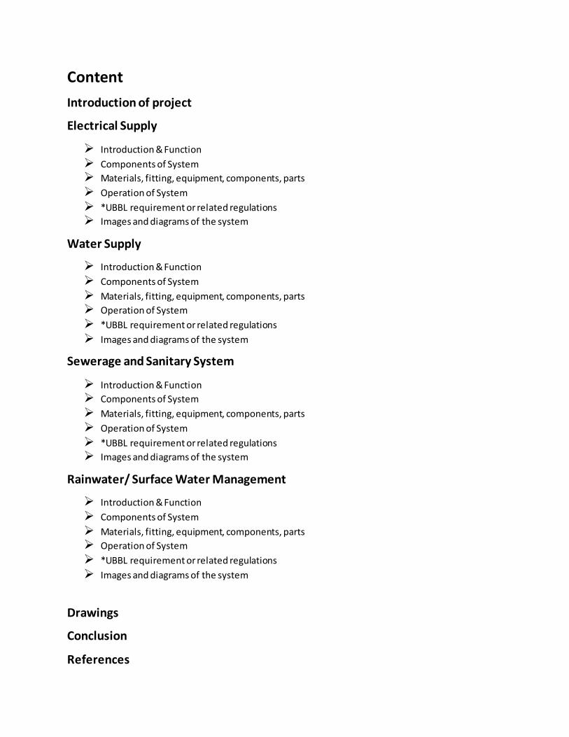
action can be taken as provided under the Electricity Supply Act 1990. The following image shows the
process of the electricity generated from the generating station and transferred to the customers’ places.
Diagram of electric supply system from generating station
Electricity provides electrical power to various parts, such as electric outlets, lighting, HVAC equipment,
communications equipment, transport systems, and as well as fire system. Electric power in a building is
very important as failure could paralyze a facility in a building. It is very crucial that proper emergency
equipment that would supply temporary electrical needs to the building is provided to the facility.
Electricity suppliers in Malaysia are differrent according to areas of the country. Electricity is distributed
by Tenaga National Berhad (TNB) in Peninsular Malaysia, whereas in Sabah and Sarawak electricity is
distributed by Sabah Electricity Sdn. Bhd. and Sarawak Energy Bhd. respectively. These electrical utility

company provides generation, transmission and distribution of electricity throughout the country. They
are involved in the services such as repairs, testing and maintenance of each equipment, as well as
construction and manufacturing of power plants to produce high voltage electricity for transmi ssion and distribution.
COMPONENTS OF SYSTEM
Electric Meter
A device used to measure the amount of electric energy consumed by a building and for billing purpose.
It can be called electricity meter, electric meter or electrical meter. The basic unit of measure of electric power is the Watt.
Image of electric meter
Distribution Box
It is also known as panelboard, breaker panel, or electric panel. It functions as a component of an
electricity supply system that divides an electrical power feed into subsidiary circuits, while providing a
protective fuse or circuit breaker for each circuit in a common enclosure.
Image of distribution box

13A Power Plug Point
A power plug point or socket outlet is the familiar item mounted on the wall into which a plug can be
inserted. It is a device that allows electrically operated equipment to be connected to the primary alternating current(AC) power supply in a building. A single socket outlet is rated 13amps.
Image of power plug point
3 Gang Switch
Switches of light fixtures and fan.
Image of 3 gang switch
Down Light
Down light is a lamp, often a light bulb set in a metal cylinder, mounted on or recessed into the ceiling
so that a beam of light is directed downward. It provides more concentrated and pleasant ambient lighting and also easy to install on the ceiling hole.
Image of down light

Ceiling Fan
A ceiling fan is a mechanical fan, usually electrically powered, suspended from the ceiling of a room, that
uses hub-mounted rotating paddles to circulate air or cool the room efficiently. It is lower in cost.
Image of ceiling fan
OPERATION OF SYSTEM
There are two types of electrical supply system, off-site power system and on-site power system. On-site
power system which is used in the school contains normal power sources such as transformers, auxiliary
power supply, cables and emergency power supply (generator). The grid, generators, transmission and distribution systems are included in the power system.
The school is considered as a small building. Hence, electrical system for this building consists of a
simple power distribution system. Electrical supply from TNB is firstly distributed to the high voltage
(HV) room of a building. Lower voltage (LV)room then receives electrical supply from HV room and
transmits electricity to risers on each floor of a building. The risers then distribute electrical supply
throughout the floors. Generator rooms can only be found in private buildings which acts as an
emergency power system. Newly developed buildings such as the school adapt the Building Automatic
System (BAS). It monitors and controls facilities through a centralized system, such as lighting, air
handling units, switchboards and CCTV.

Diagram of distribution of electricity in a building
The electricity is transmitted through an electric meter to panels, wiring and devices that are owned and
operated by the building owner. Measurement of electricity usage is done by meters, usually in kilowatt
per hour. Safety devices such as fuses and circuit breakers are used to prevent fire or damage of devices
due to over usage of electricity. Fuses have a disadvantage where it operates once and must be
replaced, unlike circuit breakers where it can be reset to function normally. Circuit breakers functions
both as a protective device as well as a switch. It allows electricity to pass through, while ensuring to
break the circuit when overloaded or short circuit. There are various types of circuit breakers to cater for
different needs. Distribution boards receives current which is then distributed through a branch circuit.
Branch circuits are commonly used due to its safety purposes. It contains a reserve capacity which
protects the circuit from over usage and short circuit. There are 3 different types of outlets used such as
single, multiple and general multiple circuits. They are generally used for appliances, small devices and
lighting respectively. Some electrical appliances such as lighting and ceiling fan require a small load, while some appliances such as air conditioners require a heavier load.
UBBL REQUIREMENT OR RELATED REGULATIONS
Electrical Supply Act 1997 Act-477
Regulation 15- Apparatus, Conductor, Accessory, etc.
1.Any conductor or apparatus that is exposed to weather, water, corrosion under heating or used in
inflammation surroundings or in an explosive atmosphere shall be constructed or protected in such a manner as to prevent danger.
Electrical Supply Act 1997 Act-477
Regulation 16- Switch, Switch Fuse, Circuit Breaker, Contractor, Fuse, etc.
3.a) Fuse and circuit breakers are arranged in such a manner as to break the current when it exceeds a
given value of sufficient time to prevent danger.
b) Constructed, guarded or placed in a manner to prevent danger of overheating and arching from the scattering of hot metals or other substances.
WATER SUPPLY SYSTEM
INTRODUCTION AND FUNCTION
A water supply system is a system that supplies the water to the water outlets such as water faucets,
shower, water closet WC and ect. This supply system includes the heating mechanism, the water
pumping mechanism, and the piping network that transports the hot and cold water throughout the
building including the valves and fittings used in the process. Water supply system starts with a water
supplier that provide water to a home, through a water main, then branch off.
COMPONENTS OF SYSTEM
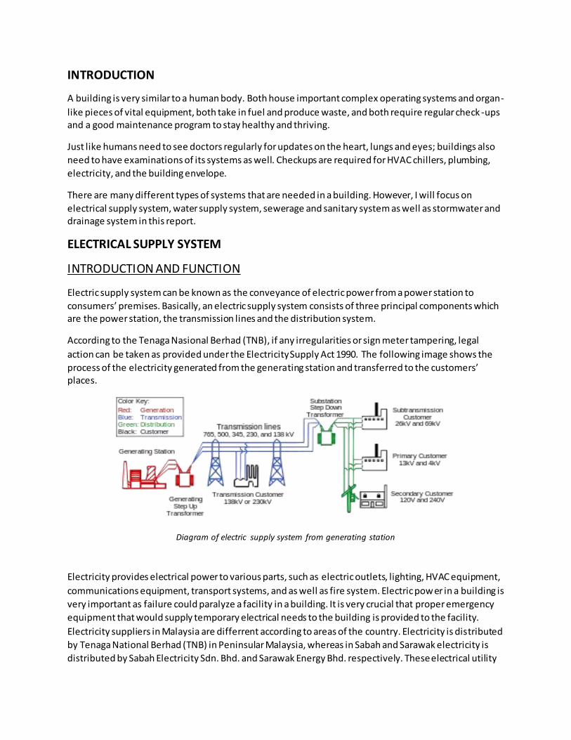
Water meter
Measure the volume of water used by residential and commercial building that are supplied with water
by a public water.
Image of water meter
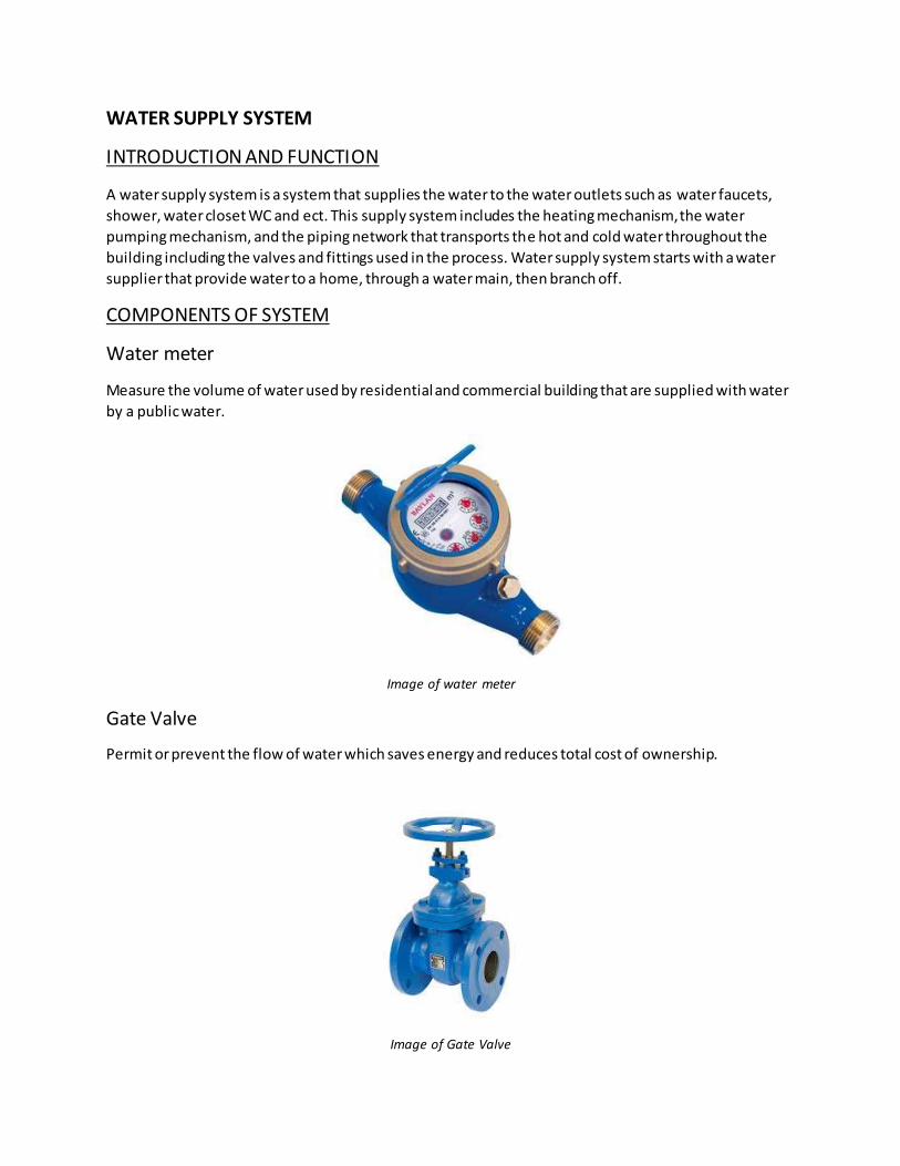
Gate Valve
Permit or prevent the flow of water which saves energy and reduces total cost of ownership.
Image of Gate Valve

Water main
This is a pipe that brings cold water directly from the water pipe in the street to the stop tap in your
building.
Image of water main
Stop tap
This component also can be called as stopcock or stop valve. It turns off the cold water into your house,
from the water coming in from the street. Stop taps are located at multiple fittings for easy maintenance
and repairs. It controls the flow of water through the pipes.
Image of stop tap
HDPE Water Tank
High density polyethylene (HDPE) tank helps to overcome persistent corrosion problems and specifically
for storing water before the distribution to other appliances. Components in the water tank:
Float operated valve - This is commonly known as a ball valve. It is a mechanical valve that automatically
opens and closes as water is removed and added to a cistern, and they come in all shapes and sizes and materials.
The warning pipe - This is commonly referred to as the overflow. It will advise the occupier that a cistern
is full and the valve is not turning off water and ‘warning’ that it could spill over the cistern sides.
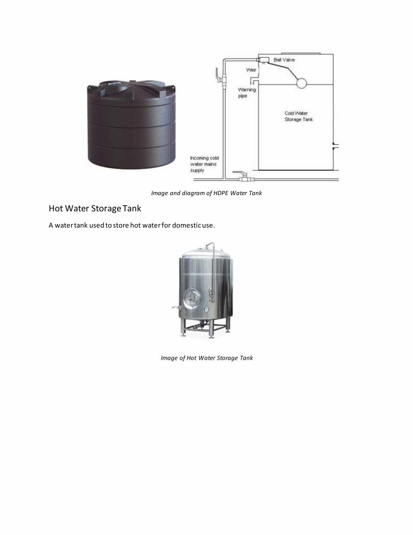
Image and diagram of HDPE Water Tank
Hot Water Storage Tank
A water tank used to store hot water for domestic use.
Image of Hot Water Storage Tank

Water Heater
Provides hot water and stored in hot water storage tank.
Image of water heater
uPVC Pipe
Conveyance and distribution heating or domestic use by potable water. Light weight and durable material.
Image of uPVC pipe
Copper Tube
To channel hot water as its surface is able to withstand impact and abrasion.
Image of Copper Tube

OPERATION OF SYSTEM
The distribution pipes of the water supply system are generally laid below the road pavements, and
their layouts generally follow the layouts of roads. In general, there are four different types of pipe networks that can be used which are dead end system, radial system, grid iron system and ring system.
Diagrams of four different types of pipe networks
The pipe network system that is used in my school is the ring system which is laid along the peripheral
roads and sub mains branch out from the mains. This system also follows the grid iron system with the
flow pattern similar in character to that of dead end system. In this way, the determination of the size of
pipes will be easier. Not only that, the water can be supplied to any point in minimum two directions.

The methods of water distribution depend on the level of source, topography of the area and other local
conditions. The few ways of methods of water distribution are gravity system, pumping system and
combined gravity and pumping system.
Diagram of gravity system
Diagram of pumping system

Diagram of combined gravity and pumping system
Gravity system is used for the school since the source of the supply is at sufficient height and this
method is the most reliable and economical distribution system.
UBBL REQUIREMENT OR RELATED REGULATIONS
UBBL Section 84
Prevention of Dampness
Suitable measures shall be taken to prevent the penetration of dampness into the building.
UBBL Section 89
Chase
A chase made in a wall for pipes and other service facilities shall leave the wall at the back of the chase
not less than 100mm thick in external walls and party walls and not wider than 200 mm.
UBBL Section 123
Pipes and Service Ducts
1.a) adequate for the accommodation of pipes, cables and conduits and for crossing of branches and mains.
b) sufficiently large to permit access to cleaning eyes, stop cocks and other controls to enable repairs and modifications.
SEWERAGE AND SANITARY SYSTEM
INTRODUCTION AND FUNCTION
Sewerage system is a system consists of sewers, pumping mains, pumping stations, sewage treatment
plants and treatment works for the collection, treatment and disposal of sewage and recovery of
industrial water and includes any industrial water main and pipe, drain-line, grease trap, cesspit, septic tank, privy and any appurtenance thereof.
Sanitary plumbing system is a system consists of sanitary pipework above the ground comprising one or
more discharge pipes, discharge stacks, ventilating pipes, ventilating stacks and fittings for the
conveyance of sewage from premises to a sanitary drainage system.
A building can be served by an internal sanitary plumbing and drainage system. This internal sanitary
plumbing and drainage system shall be connected to public sewers by an internal drain-line maintained by the owner or occupier of the development.
COMPONENTS OF SYSTEM
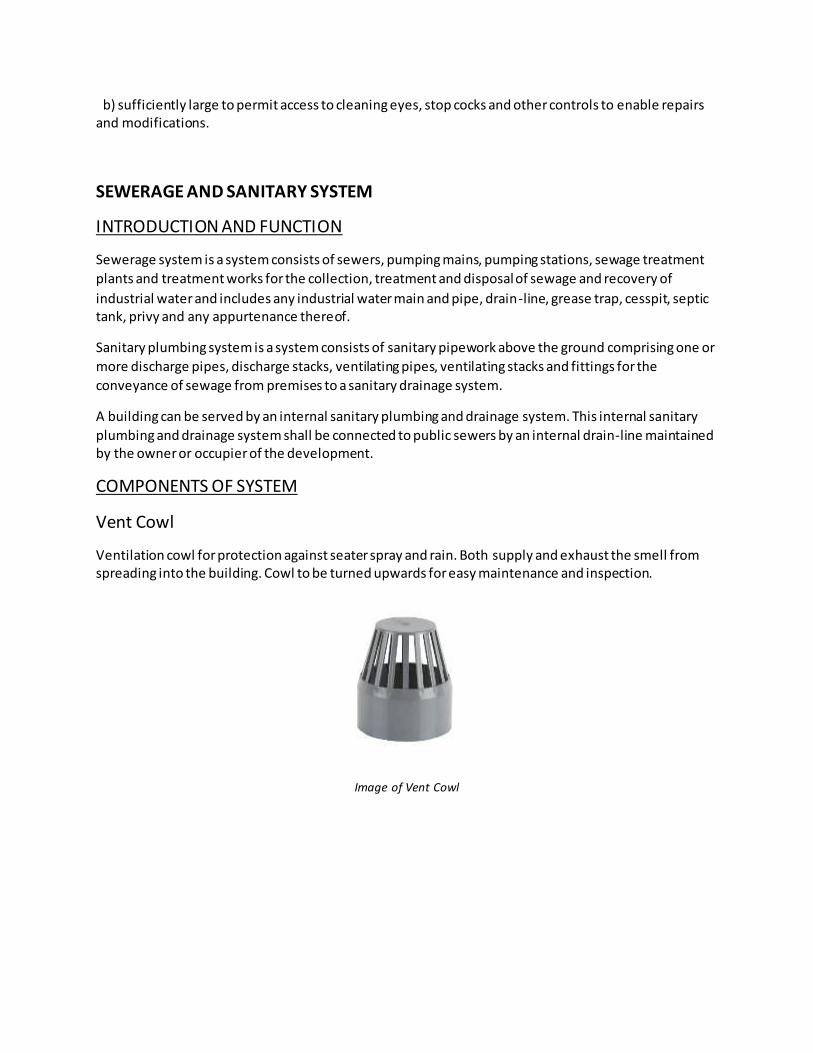
Vent Cowl
Ventilation cowl for protection against seater spray and rain. Both supply and exhaust the smell from spreading into the building. Cowl to be turned upwards for easy maintenance and inspection.
Image of Vent Cowl
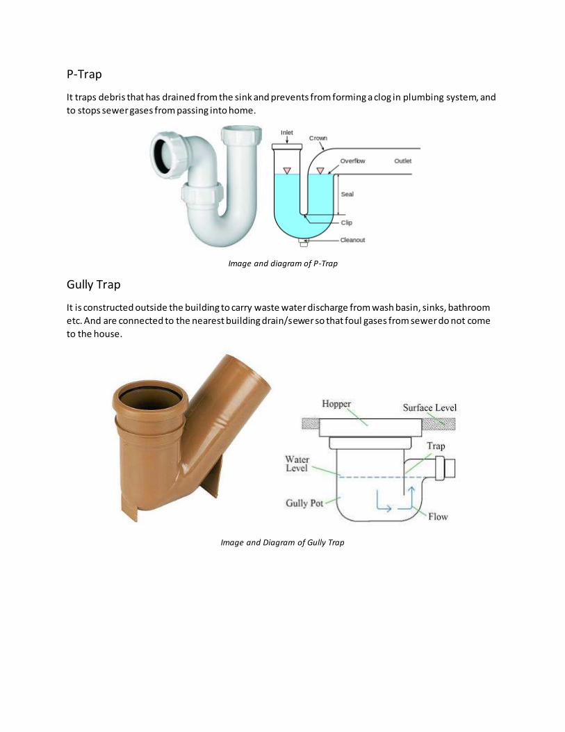
P-Trap
It traps debris that has drained from the sink and prevents from forming a clog in plumbing system, and
to stops sewer gases from passing into home.
Image and diagram of P-Trap
Gully Trap
It is constructed outside the building to carry waste water discharge from wash basin, sinks, bathroom
etc. And are connected to the nearest building drain/sewer so that foul gases from sewer do not come
to the house.
Image and Diagram of Gully Trap
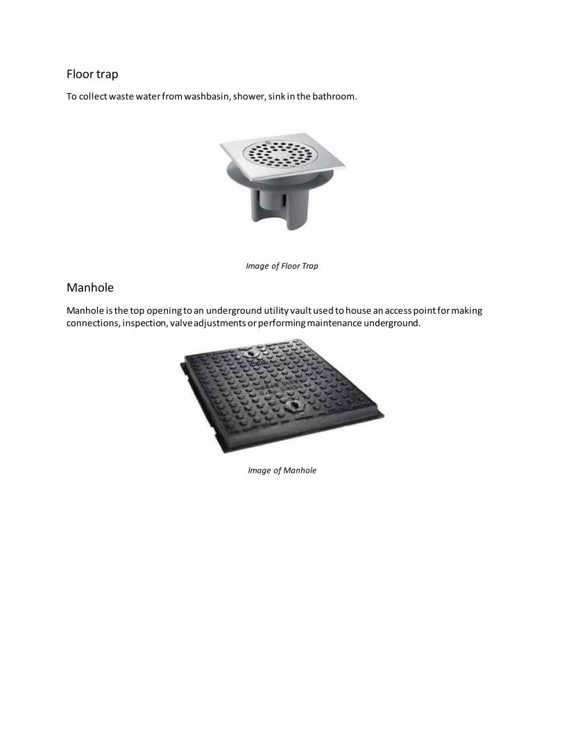
Floor trap
To collect waste water from washbasin, shower, sink in the bathroom.
Image of Floor Trap
Manhole
Manhole is the top opening to an underground utility vault used to house an access point for making connections, inspection, valve adjustments or performing maintenance underground.
Image of Manhole
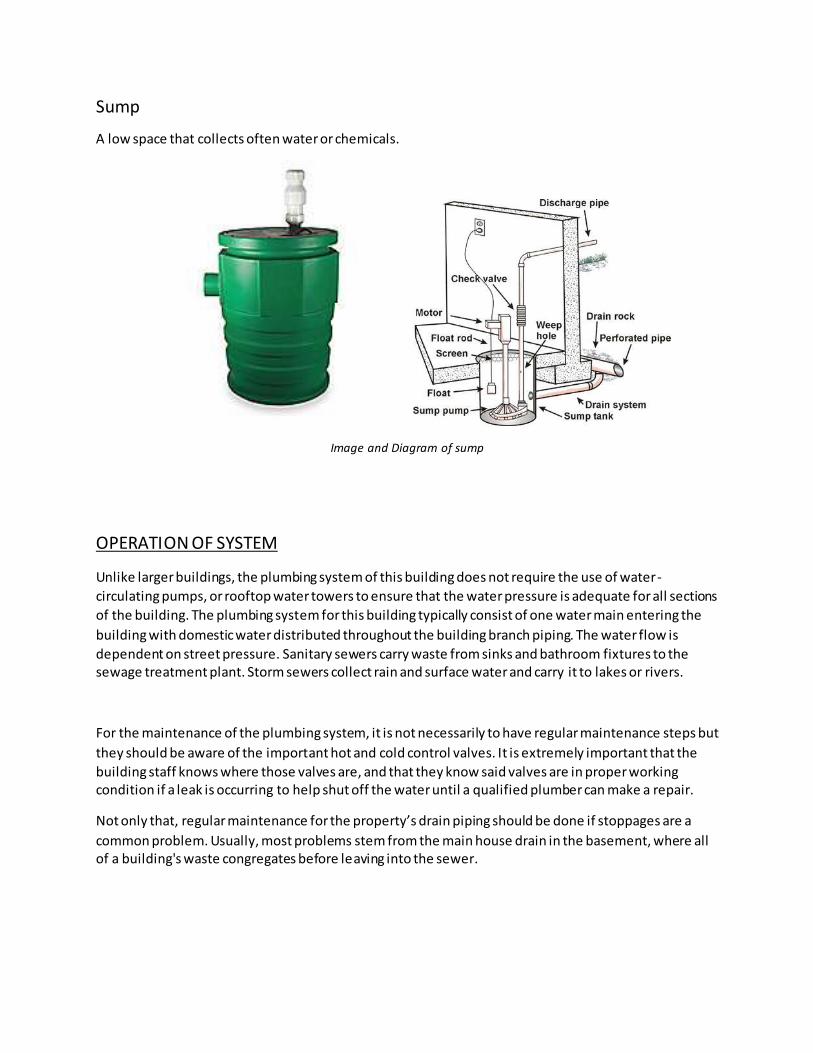
Sump
A low space that collects often water or chemicals.
Image and Diagram of sump
OPERATION OF SYSTEM
Unlike larger buildings, the plumbing system of this building does not require the use of water-
circulating pumps, or rooftop water towers to ensure that the water pressure is adequate for all sections
of the building. The plumbing system for this building typically consist of one water main entering the
building with domestic water distributed throughout the building branch piping. The water flow is
dependent on street pressure. Sanitary sewers carry waste from sinks and bathroom fixtures to the sewage treatment plant. Storm sewers collect rain and surface water and carry it to lakes or rivers.
For the maintenance of the plumbing system, it is not necessarily to have regular maintenance steps but
they should be aware of the important hot and cold control valves. It is extremely important that the
building staff knows where those valves are, and that they know said valves are in proper working condition if a leak is occurring to help shut off the water until a qualified plumber can make a repair.
Not only that, regular maintenance for the property’s drain piping should be done if stoppages are a
common problem. Usually, most problems stem from the main house drain in the basement, where all of a building's waste congregates before leaving into the sewer.
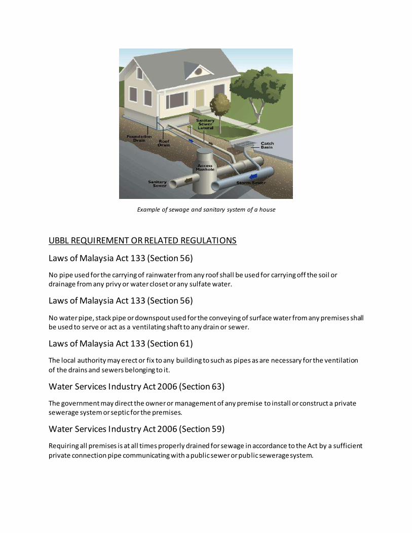
Example of sewage and sanitary system of a house
UBBL REQUIREMENT OR RELATED REGULATIONS
Laws of Malaysia Act 133 (Section 56)
No pipe used for the carrying of rainwater from any roof shall be used for carrying off the soil or drainage from any privy or water closet or any sulfate water.
Laws of Malaysia Act 133 (Section 56)
No water pipe, stack pipe or downspout used for the conveying of surface water from any premises shall be used to serve or act as a ventilating shaft to any drain or sewer.
Laws of Malaysia Act 133 (Section 61)
The local authority may erect or fix to any building to such as pipes as are necessary for the ventilation
of the drains and sewers belonging to it.
Water Services Industry Act 2006 (Section 63)
The government may direct the owner or management of any premise to install or construct a private sewerage system or septic for the premises.
Water Services Industry Act 2006 (Section 59)
Requiring all premises is at all times properly drained for sewage in accordance to the Act by a sufficient
private connection pipe communicating with a public sewer or public sewerage system.

RAINWATER/SURFACE WATER DRAINAGE SYSTEM
INTRODUCTION AND FUNCTION
Rainwater or surface water drainage happens when rainwater falls on a property and drains away. The
design of the rainwater or surface water drainage system has to consider about the flow of the water, suitable dimensions of the components of system as well as the materials of the components used.
COMPONENTS OF SYSTEM
Rainwater Downpipe
Downpipes are usually vertical and usually extend down to ground level. The water is directed away
from the building’s foundation to protect the foundations from water drainage. The water is usually
piped to a sewer, or let into the ground.
Image and Diagram of Rainwater Downpipe

Gutter
Installed on the eaves of the roof. Which collects rainwater from the roof of a building and diverts away
from the rainwater downpipe to the drain.
Image of Gutter
Drain Sump
Drain sump is a pit or reservoir serving as a drain or receptacle for liquids. It locates at the lowest point
in a circulating or drainage system.
Image of Drain Sump

Drainage
Drainage is the natural or artificial removal of a surfaces and its sub-surface water from an area.
Image of Perimeter Drainage
200mm Subsoil UPVC Pipe
Pipe placed slightly below the soil level.
Image of a subsoil UPVC pipe
OPERATION OF SYSTEM
There are two systems of drainage which are 'foul' and 'surface water' and these two systems should be
kept separate. Each of these systems has above-ground and underground elements.
For foul drainage, it carries the used water from toilets, sinks, basins, baths, showers, bidets,
dishwashers and washing machines. The above-ground pipework is referred to as sanitary pipework; the
underground pipework is referred to as foul drains and foul sewers. And this drainage is concluded in
sanitary system.
Surface water drainage carries rainwater from hard surfaces. The above-ground system of gutters and
rainwater pipes is referred to as roof drainage; the underground pipework is referred to as surface water drains and surface water sewers.
To compare drainage and sewer, we can conclude that a drain serves a single property whereas a sewe r
serves more than one property

The system of the school works by piping using gravity. Pipes are positioned, selected and laid so that
the natural fall of the land helps transport the stormwater. Stormwater is usually transported by a kerb
and gutter system or an underground stormwater drain. The component pipe sizes are chosen according
to the area over which the rain is collected and the rainfall intensity. Rainfall intensity is defined as how
much rain falls over a given period of time. Piping for stormwater drains is usually constructed from PVC,
reinforced concrete or Fibre Reinforced Cement (FRC)
Open channels also are used in this system. Open drainage channel is used in preference to piping
because it is cheaper and more effective in areas prone to flooding. As a common example, the concrete
kerb and channel at the side of a street. They use the natural fall of the land for the flow. The depth and
width of the channel will depend on the volume of stormwater that it is expected to handle. Channels
may be made of concrete, brick or other solid and durable materials. It is not recommended to use soil channels as these are very prone to erosion.
Diagram of Storm Drain system
UBBL REQUIREMENT OR RELATED REGULATIONS
Laws of Malaysia Act 133 (Section 56)
No pipe used for the carrying of rainwater from any roof shall be used for carrying off the soil or
drainage from any privy or water closet or any sulfate water.
Laws of Malaysia Act 133 (Section 56)
No water pipe, stack pipe or downspout used for the conveying of surface water from any premises shall be used to serve or act as a ventilating shaft to any drain or sewer.
UBBL Section 115
All roof of building shall be constructed to drain effectively and sufficient channel shall be provided in
accordance with the requirement of these laws for receiving and conveying all water which may fell on and from the roof.

SUMMARY/CONCLUSION
After completing this assignment, I learned to identify relevant information related to water and
electrical supply, liquid waste disposal, sanitary as well as rainwater management system. After this, I
able to describe the planning of building services within the design and construction peripheries. I learned to propose the more suitable systems for a specific type of a building.
REFERENCES
1. Chudley, Roy. 1988. Building Finishes, Fittings and Domestic Services. 2nd Edition. Longman.
2. Soh Shing Follow. (2014, December 05). Building services report. Retrieved July 05, 2017, from
https://www.slideshare.net/sohshing/building-services-report
3. How Do Our Water Systems Work? (n.d.). Retrieved July 05, 2017, from
http://www.valueofwater.ca/water-facts/how-do-our-water-systems-work/
4. Ashikin Follow. (2015, April 13). Cold water supply system & Components. Retrieved July 05,
2017, from https://www.slideshare.net/manshe82/t2-cold-water-supply-system
5. Syafiq Zariful Follow. (2015, June 27). Hot Water Supply Report BS1. Retrieved July 05, 2017,
from https://www.slideshare.net/syafiqzariful/hot-water-supply-report-bs1
6. Groundwork. (n.d.). Retrieved July 05, 2017, from
https://www.dlsweb.rmit.edu.au/toolbox/plumbing/toolbox12_01/units/cpcpdr4002a_stormw
ater/00_groundwork/page_003.htm
7. Keeping Basements Dry. (n.d.). Retrieved July 05, 2017, from
http://www.ashireporter.org/homeinspection/articles/keeping-basements-dry/1048