building the pool of available cloud resources
TRANSCRIPT

Administrator Portal Guide, Release 1.1, Part: CCAMCP-CNAP-Admin1-1.1
C H A P T E R 3
Building the Pool of Available Cloud ResourcesYou have to add a variety of resources to Cisco CNAP to form the pool of devices and addresses that you can use in your clouds. This involves:
• Configuring Data Center Devices
• Configuring Network Pools and Configuring Address Pools
You use Cisco CNAP to specify your IP addressing scheme details so that those IP addresses, VLAN pools, subnets, etc. are available during container creation.
You must specify:
– The VLAN ranges and their associated VLAN pools that you will be utilizing when creating network plans. When you add a VLAN range, Cisco CNAP populates the VLAN pool.
– How IP subnets and their associated IP address pools will be utilized, such as for Infrastructure, Management, NAT, Shared Services, or Tier.
You can also configure access to Shared Services, such as Database as a Service (DBaaS), Disaster Recovery as a Service (DRaaS), etc., that you want to be available as options when you are creating and configuring network container plans. For more information, see Configuring Access to Shared Services.
Note Since Cisco CNAP is also pushing configurations for the automation of work flows on devices, certain precautions need to be followed when manually configuring devices to avoid disrupting Cisco CNAP-based automation. Changing configurations pushed from Cisco CNAP will cause the automated provisioning system to malfunction, which in some cases could cause all automated provisioning to stop until the error conditions are manually remediated. In general on the data center provider edge, all configurations under the tenant VRFs pushed by Cisco CNAP should not be edited or changed, including sub-interfaces and routing. Similarly on the Cisco APIC, the Cisco APIC tenants configured by Cisco CNAP should only be changed by Cisco CNAP. Any configurations pushed by Cisco CNAP should not be manually edited. For more information, see Installing Cisco Cloud Network Automation Provisioner for the Microsoft Cloud Platform, Release 1.1.
Configuring Data Center DevicesYou add network devices to form the pool of infrastructure resources available to a cloud. Network devices are associated with a specific cloud. In the current release, only one cloud is supported.
3-1Cisco Cloud Network Automation Provisioner

Chapter 3 Building the Pool of Available Cloud Resources Configuring Data Center Devices
Note Enter device information carefully. In the current release, you cannot modify device information once you have added it. If you want to make changes after you have added a device, you must delete the device and add it again.
You must initially add the following three devices before you can perform network provisioning:
• Cisco Network Services Orchestrator Enabled by Tail-f
• Cisco Aggregation Services Router—Cisco ASR 9000 or Cisco ASR 1000 (WAN Gateway)
Note If you are manually provisioning WAN Edge/PE, you do not have to add a Cisco ASR 9000 or ASR 1000. For more information on manual provisioning, see Understanding the Difference Between Auto-provisioning and Manually Provisioning WAN Gateways in Chapter 5, “Managing Container Plans.”
• Cisco Application Policy Infrastructure Controller (APIC)—SDN switching fabric
Note Before you add the Cisco APIC, you must create a directory to store the Cisco APIC configurations. As the admin user (or ensure the admin user has read and write access to the directory), create the directory:/home/admin/cisco-apicdc
If you are going to configure access to Shared Services, such as DBaaS, DRaaS, etc., you should add a:
• Cisco Adaptive Security Appliance 5585 (Cisco ASA 5585) firewall to be used as the security access point to the Shared Services. The firewall context defined on the Cisco ASA 5585 must be preconfigured. For more information, see Cisco Cloud Architecture for the Microsoft Cloud Platform: Infrastructure Foundation Guide, Release 1.0.
You can also delete devices if necessary. Virtual network devices that are created by Cisco CNAP are displayed but cannot be deleted.
Adding a Cisco Network Services Orchestrator Enabled by Tail-fYou should have performed this step as part of the Cisco CNAP installation because the Cisco NSO should be the first network device you add.
For more information, see the section Connecting Cisco Cloud Network Automation Provisioner to the Cisco Network Services Orchestrator in Installing Cisco Cloud Network Automation Provisioner for the Microsoft Cloud Platform, Release 1.1.
Adding a Cisco ASR, Cisco APIC, and Cisco ASA 5585After you add the Cisco NSO, the next two devices you should add are:
• Cisco Aggregation Services Router—Cisco ASR 9000 or Cisco ASR 1000 (WAN Gateway)
• Cisco Application Policy Infrastructure Controller (APIC)—SDN switching fabric
3-2Cisco Cloud Network Automation Provisioner
Administrator Portal Guide, Release 1.1, Part: CCAMCP-CNAP-Admin1-1.1

Chapter 3 Building the Pool of Available Cloud Resources Configuring Data Center Devices
Note Before you add the Cisco APIC, you must create a directory to store the Cisco APIC configurations. As the admin user (or ensure the admin user has read and write access to the directory), create the directory:/home/admin/cisco-apicdc
Note When used with Cisco CNAP, the Cisco APIC cluster should be front-ended by a Server Load Balancer (SLB) and you should set up an HTTPS bridging session, which allows registration of one IP address on Cisco CNAP for the Cisco APIC cluster (basically the SLB VIP). Cisco CNAP expects a single IP address for the Cisco APIC cluster, which may have three or more nodes.
To add a Cisco ASR and Cisco APIC:
Step 1 On the Network Devices Tab screen, in the Cloud drop-down, click the cloud service to which you want to add a device, as shown in the following screen.
Figure 3-1 Network Devices Tab Screen
Step 2 Click Add.
You see the Add Network Device screen.
3-3Cisco Cloud Network Automation Provisioner
Administrator Portal Guide, Release 1.1, Part: CCAMCP-CNAP-Admin1-1.1

Chapter 3 Building the Pool of Available Cloud Resources Configuring Data Center Devices
Figure 3-2 Add Network Device Screen
The Type pull-down menu displays the devices you can add, as shown in the following screen.
3-4Cisco Cloud Network Automation Provisioner
Administrator Portal Guide, Release 1.1, Part: CCAMCP-CNAP-Admin1-1.1
Chapter 3 Building the Pool of Available Cloud Resources Configuring Data Center Devices
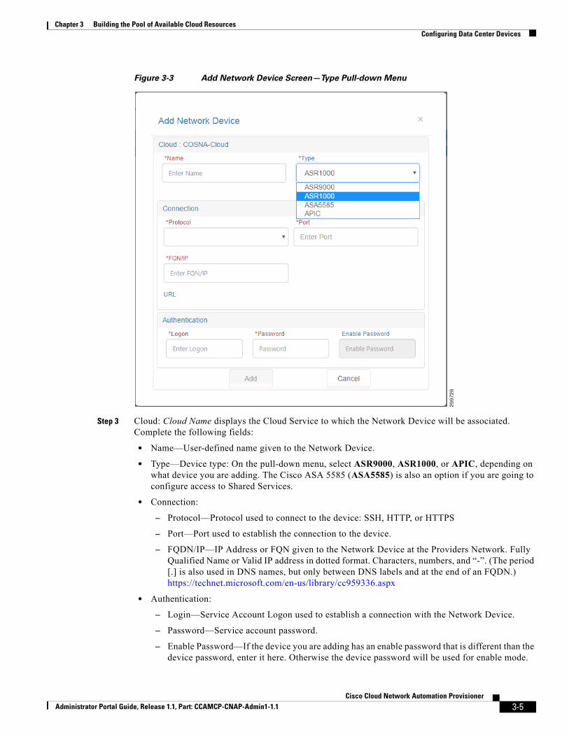
Figure 3-3 Add Network Device Screen—Type Pull-down Menu
Step 3 Cloud: Cloud Name displays the Cloud Service to which the Network Device will be associated. Complete the following fields:
• Name—User-defined name given to the Network Device.
• Type—Device type: On the pull-down menu, select ASR9000, ASR1000, or APIC, depending on what device you are adding. The Cisco ASA 5585 (ASA5585) is also an option if you are going to configure access to Shared Services.
• Connection:
– Protocol—Protocol used to connect to the device: SSH, HTTP, or HTTPS
– Port—Port used to establish the connection to the device.
– FQDN/IP—IP Address or FQN given to the Network Device at the Providers Network. Fully Qualified Name or Valid IP address in dotted format. Characters, numbers, and “-”. (The period [.] is also used in DNS names, but only between DNS labels and at the end of an FQDN.) https://technet.microsoft.com/en-us/library/cc959336.aspx
• Authentication:
– Login—Service Account Logon used to establish a connection with the Network Device.
– Password—Service account password.
– Enable Password—If the device you are adding has an enable password that is different than the device password, enter it here. Otherwise the device password will be used for enable mode.
3-5Cisco Cloud Network Automation Provisioner
Administrator Portal Guide, Release 1.1, Part: CCAMCP-CNAP-Admin1-1.1

Chapter 3 Building the Pool of Available Cloud Resources Configuring Data Center Devices
Step 4 Click Add to add the network device or Cancel to cancel the addition.
Step 5 Repeat the procedure for the other device(s) you must add, such as a Cisco ASR 9000, Cisco ASR 1000, Cisco ASR 5585, or Cisco APIC.
Deleting a Network Device
Step 1 On the Network Devices Tab Screen, in the Cloud tree on the left, click the cloud service containing the device you want to delete.
Note You can delete an existing Network Device only if the device is not being used by a network container, irrespective of whether the device is Active or Inactive.
Step 2 Click the specific device you want to delete, then click the Delete button.
You see the Delete Network Device screen.
Figure 3-4 Delete Network Device Screen
3-6Cisco Cloud Network Automation Provisioner
Administrator Portal Guide, Release 1.1, Part: CCAMCP-CNAP-Admin1-1.1

Chapter 3 Building the Pool of Available Cloud Resources Configuring Network Pools
Step 3 Click Remove to remove the network device or Cancel to cancel the deletion.
Configuring Network PoolsYou must specify the VLAN ranges and their associated VLAN pools that you will be utilizing when creating network plans. When you add a VLAN range, Cisco CNAP populates the VLAN pool.
For example, when you create a WAN Gateway, Cisco CNAP will acquire a VLAN ID from the VLAN pool and mark it as allocated.
On the Network Pool tab, you can:
• Add VLAN Ranges to the available Cloud resources.
• Once added, manage the VLAN ranges and VLAN IDs.
Important Considerations When Configuring Network PoolsYou must take into consideration the following configuration requirements and recommendations:
• You must add a VLAN pool for the Cisco ASR 9000 or ASR 1000 with the same range as the VLAN pool defined on the Cisco APIC for use with the Cisco ASR 9000 or ASR 1000. On the Cisco APIC, the VLAN pool for the Cisco ASR 9000 or ASR 1000 should be assigned to a Physical Domain so it can be used to configure the trunk between the Cisco ASR 9000 or ASR 1000 and the Cisco APIC.
• It is recommended to use separate VLAN pools in Cisco CNAP for auto-provisioned and manually-provisioned WAN Edge/PEs. This lets you allocate and unallocate the VLANs for manually-provisioned WAN Edge/PEs separate from auto-provisioned WAN Edge/PEs, thereby eliminating overlapping VLAN issues. Cisco APIC, however, can use a single VLAN pool for auto-provisioned and manually-provisioned WAN Edge/PEs.
Managing Network PoolsYou use the Network Pool tab to manage the VLANs that will be used during the orchestration of Network Containers. A group of VLANs make up each VLAN Range (on the Network Pool tab, the group of VLANs in a particular VLAN Range is also called the VLAN Pool). All of the VLAN Ranges collectively make up the Network Pool.
In the current release of Cisco CNAP, one VLAN Range must be created for WAN connectivity between data center PE routers and the Cisco ACI Fabric. Note that the VLAN Range entered into Cisco CNAP must be consistent with configurations on the Cisco ACI VLAN pools associated with the external in-terfaces to the data center PEs.
You can:
• Look at information about VLANs.
• Add a new VLAN Range.
• Mark a VLAN Range as available thereby automatically Unallocating all the VLANs in its VLAN Pool.
• Unallocate a VLAN ID.
• Remove a VLAN Range.
3-7Cisco Cloud Network Automation Provisioner
Administrator Portal Guide, Release 1.1, Part: CCAMCP-CNAP-Admin1-1.1

Chapter 3 Building the Pool of Available Cloud Resources Configuring Network Pools
Viewing Information about VLANs
Figure 3-5 Network Pool Tab Screen
If you click on a specific entry in the VLAN Range table, you see the associated VLAN Pool, as shown in the following screen.
3-8Cisco Cloud Network Automation Provisioner
Administrator Portal Guide, Release 1.1, Part: CCAMCP-CNAP-Admin1-1.1

Chapter 3 Building the Pool of Available Cloud Resources Configuring Network Pools
Figure 3-6 VLAN Pool for Selected VLAN Range Screen
The Network Pools tab contains the following:
• The VLAN Range table contains the following fields:
– Cloud—Name of the cloud.
– VLAN IDs—A range of VLAN IDs in the format: “Start Vlan ID - End Vlan ID”.
– State—State of the VLAN Range, which is either Available or Unavailable. A VLAN Range is said to be Available when it still has VLANs that are not yet Allocated. The VLAN Range is marked Unavailable once all the constituent VLANs have been allocated.
– Group—The VLAN Range group, which in the current release is Infrastructure for all VLANs. Infrastructure VLANs are used to “stitch” the provider edge (PE) to the customer edge (CE). In future releases, there may be container patterns that require these VLANs to be managed through Cisco CNAP by the user.
– Created On—Date and time when the VLAN Range was created.
– Modified On—Date and time when the VLAN Range was last modified.
• For the selected VLAN Range, the VLAN Pool table contains the following fields:
– VLAN ID—Numeric value representing a VLAN.
– Name—The Tenant Name.
3-9Cisco Cloud Network Automation Provisioner
Administrator Portal Guide, Release 1.1, Part: CCAMCP-CNAP-Admin1-1.1

Chapter 3 Building the Pool of Available Cloud Resources Configuring Network Pools
– State—State of the VLAN, which is either Allocated or Unallocated. A VLAN will be marked “Unallocated” as long as it has not been used by any network component in the backend. Once it has been consumed by the network, the backend will mark it as “Allocated”.
– Allocated On—Date and time when the VLAN was allocated.
– Modified On—Date and time when the VLAN was last modified.
• Add Button—Lets you add a new VLAN Range and its corresponding VLANs to the system.
• Available Button—Should only be used for emergency clean up. For example, if the system crashes and the configurations on the devices are corrupted or destroyed, but the database still reflects the VLAN Ranges as being unavailable. The Available button marks the selected VLAN Range as available and all the constituent VLANs as Unallocated. It does not decouple the constituent VLANs from the network components to which they may or may not be coupled (such as PE<—>CE stitching).
• Unallocate Button—Should only be used for emergency clean up. For example, if the system crashes and the configurations on the devices are corrupted or destroyed, but the database still reflects the VLANs as being Allocated. The Unallocate button marks the selected VLAN as Unallocated. It does not decouple the constituent VLANs from the network components to which they may or may not be coupled (such as PE<—>CE stitching).
• Delete Button—Lets you remove an existing VLAN Range from the system if it is not allocated to any tenant. and none of its VLANs are in the Allocated state.
Adding a New VLAN Range
Step 1 To add a new VLAN Range, select a Cloud in the VLAN Range table and click the Add button.
You see the Add VLAN Range screen.
Figure 3-7 Add VLAN Range Screen
Step 2 Enter information in the following fields:
• Range Info:
– Start—The Starting VLAN ID on the Range. Enter a numeric value in the range [0,4096].
– End—The Ending VLAN ID on the Range. Enter a numeric value in the range (Start, 4096].
3-10Cisco Cloud Network Automation Provisioner
Administrator Portal Guide, Release 1.1, Part: CCAMCP-CNAP-Admin1-1.1

Chapter 3 Building the Pool of Available Cloud Resources Configuring Network Pools
– Group—The VLAN Range group, which in the current release is Infrastructure for all VLANs. Infrastructure VLANs are used to “stitch” the provider edge (PE) to the customer edge (CE). In future releases, there may be container patterns that require these VLANs to be managed through Cisco CNAP by the user.
– Cloud—Name of the Cloud Service given to it in SCVMM.
• VLAN Blocks:
Note If you use VLAN blocks, the range should be an exact multiple of the block size. For example, VLAN range 101-300, block size of 10.
– Split Range in Blocks—Indicates whether or not the VLAN Range needs to be divided up into smaller VLAN Range blocks, which lets you add and delete in smaller blocks. If the value is true, then the VLAN Range defined by Start and End needs to be divided up into smaller VLAN Range blocks or else the VLAN Range will not be split.
– Size—Total number of VLANs on each block. Enter a numeric value ≤ (End - Start).
Step 3 Click Add to add the VLAN Range or Cancel to cancel the addition.
Making a VLAN Range and Specific VLAN Pool Available
Note New VLANs are Available by default. The Available button is active only if all the VLANs in a given range are allocated and the VLAN range itself is allocated.
Step 1 To make a VLAN Range and specific VLAN Pool available, on the Network Pool tab select a VLAN Range and a VLAN Pool, as shown in the following screen.
3-11Cisco Cloud Network Automation Provisioner
Administrator Portal Guide, Release 1.1, Part: CCAMCP-CNAP-Admin1-1.1

Chapter 3 Building the Pool of Available Cloud Resources Configuring Network Pools
Figure 3-8 Select VLAN Range and Pool
Step 2 Click Available.
You see the Make VLAN Range Available screen.
3-12Cisco Cloud Network Automation Provisioner
Administrator Portal Guide, Release 1.1, Part: CCAMCP-CNAP-Admin1-1.1

Chapter 3 Building the Pool of Available Cloud Resources Configuring Network Pools
Figure 3-9 Make VLAN Range Available Screen
Step 3 Click Available to make the VLAN Range available or Cancel to cancel the operation.
If you click Available, you see the following screen.
Figure 3-10 Make VLAN Range Available—Warning Screen
Step 4 To make the VLAN Range available, click Yes, continue!
3-13Cisco Cloud Network Automation Provisioner
Administrator Portal Guide, Release 1.1, Part: CCAMCP-CNAP-Admin1-1.1

Chapter 3 Building the Pool of Available Cloud Resources Configuring Network Pools
Unallocating a VLAN ID
Step 1 To unallocate a specific VLAN, on the Network Pool tab select a VLAN Pool, then click Unallocate.
Note On the Network Pools tab, you cannot de-couple a VLAN from the configurations in which it may be a part. Unallocating a VLAN merely resets a flag in the database and makes this VLAN available to Cisco CNAP. It does not actually remove it from any network configuration in which it may be a part.
You see the Unallocate VLAN screen.
Figure 3-11 Unallocate VLAN Screen
Step 2 Click Unallocate to unallocate the specified VLAN ID or Cancel to cancel the operation.
Removing a VLAN Range
Step 1 To remove a VLAN Range, on the Network Pool tab select a VLAN Range, then click Delete.
You see the Remove VLAN Range screen.
3-14Cisco Cloud Network Automation Provisioner
Administrator Portal Guide, Release 1.1, Part: CCAMCP-CNAP-Admin1-1.1

Chapter 3 Building the Pool of Available Cloud Resources Configuring Address Pools
Figure 3-12 Remove VLAN Range Screen
Step 2 Click Remove to remove the specified VLAN Range or Cancel to cancel the operation.
Configuring Address PoolsYou must specify how IP subnets and their associated IP address pools will be utilized, such as for In-frastructure, Management, NAT, Shared Services, or Tier.
You use the Address Pool tab to manage the IP addresses and IP subnets that are used during the orches-tration of network containers. IP addresses and IP subnets are associated with a specific cloud.
You can:
• Look at information about IP addresses and IP subnets
• Add a new IP subnet
• Remove an IP subnet
Important Considerations When Configuring Address PoolsYou should carefully consider your IP addressing scheme and how you plan to use it when configuring address pools.
Table 3-1 shows the various IP subnet groups and how they are used by Cisco CNAP. Each subnet group is described in more detail in the following sections.
3-15Cisco Cloud Network Automation Provisioner
Administrator Portal Guide, Release 1.1, Part: CCAMCP-CNAP-Admin1-1.1

Chapter 3 Building the Pool of Available Cloud Resources Configuring Address Pools
You must take into consideration the following configuration requirements and recommendations:
• You must create a separate Management IP subnet pool for each cloud.
• The IP subnet you plan to use to manage the Cisco CSR 1000Vs and the Citrix NetScaler VPXs must be assigned to the Management Group and must be large enough to accommodate the required number of Cisco CSR 1000Vs and Citrix NetScaler VPXs.
• You must define a Public Infrastructure subnet that will be used for BGP routing between the Cisco CSR 1000Vs and the Cisco ASR 9000 or ASR 1000.
• If you are configuring access to Shared Services, you must add a Public NAT subnet.
• If you are manually provisioning WAN Edge/PE for Shared Services, you must add a SharedService firewall subnet, which will be Private and the owner is provider auto. Since every tenant requires three (3) unique IP addresses, a subnet mask of /22 can provide addresses for 300 tenants.
• You can define a Private Infrastructure subnet for Layer 3 VPN, however you do not have to. If you do not, Cisco CNAP will allocate IP addresses for Private Infrastructure with /29 if none are configured.
• You can define a Tier subnet, however you do not have to. If you do not, Cisco CNAP will allocate IP addresses for Tier if none are configured.
Infrastructure Subnet Group
The Infrastructure subnet group consists of Private and Public IP subnets.
Table 3-1 IP Subnet Groups—Categories of IP Pools Consumed by Cisco CNAP
Subnet Group Description
Infrastructure
Group of subnets used for stitching core network elements of the container (Public or Private).
For example, the L3VPN interface on the Cisco CSR 1000V uses a Private IP subnet from this group. A Public IP subnet is used for the loopback address on the Cisco CSR 1000V.
TierGroup of subnets used in the provisioning of network segments in a tier (Private). Tier1, Tier2, Tier3, and DMZ have unique IP subnets from this group.
ManagementGroup of subnets used for device management and other management functions. The Cisco CSR 1000V and Citrix NetScaler VPX management IP addresses use this pool.
Internet (not available in current release)
Subnet used for Internet interface on Cisco CSR 1000V. This is typically a large subnet, such as /22, as each Zinc container would require three IP addresses for stitching the Cisco CSR 1000V to the shared Internet subnet.
NATGroup of subnets used for Dynamic and Static NATs. The NAT address pool uses public IP addresses. Each Cisco CSR 1000V is assigned a /32 address from this subnet pool.
VIP (not available in current release)
Group of subnets used for DMZ VIPs. This pool uses Public IP addresses.
SharedService
Group of subnets used for Shared Services firewall when manually provisioning WAN Edge/PE (i.e., subnets used for connecting Cisco CSR 1000V to a Shared Service firewall when the L3VPN path is not used for Shared Service access). This is a private IP subnet shared across multiple tenants. Each tenant requires three IP addresses from this pool.
3-16Cisco Cloud Network Automation Provisioner
Administrator Portal Guide, Release 1.1, Part: CCAMCP-CNAP-Admin1-1.1

Chapter 3 Building the Pool of Available Cloud Resources Configuring Address Pools
A Private subnet with /29 network mask is used for stitching the Cisco CSR 1000V to the PE devices. This subnet is overlapping across tenants. Cisco CNAP uses the IP addressing scheme in Table 3-2 for L3VPN connectivity when a Zinc container is provisioned.
The Loopback IP address is derived from an IP address pool of type Public. Each Cisco CSR 1000V will inherit an IP address from this pool with a /32 network mask.
Tier Subnet Group
Each workload tier by default requires a Private IP subnet with a mask of /26 or lower. The first 20 IP addresses are reserved by Cisco CNAP for various purposes, as shown in Table 3-3. A /24 subnet is used in this example.
Table 3-2 Infrastructure Subnet Group
Subnet IP address Purpose
10.5.0.0/29
10.5.0.0 Subnet Address
10.5.0.1 Cisco ASR 9000/ASR1000 Primary PE device
10.5.0.2 Cisco ASR 9000/ASR1000 Secondary PE device
10.5.0.3 L3VPN interface on Cisco CSR 1000V Primary
10.5.0.4 L3VPN interface on Cisco CSR 1000V Secondary
10.5.0.5 HSRP address on Cisco CSR 1000V
10.5.0.6 Not used
10.5.0.7 Broadcast Address
Table 3-3 Tier Subnet Group
Subnet IP address Purpose
192.168.1.0/24 192.168.1.0 Subnet Address
192.168.1.1 Cisco CSR 1000V Primary
192.168.1.2 Cisco CSR 1000V Secondary
192.168.1.3 Cisco CSR 1000V HSRP
192.168.1.4 Citrix NetScaler VPX Primary and Secondary
192.168.1.5 Citrix NetScaler VPX Source NAT
192.168.1.6-192.168.1.10 SLB VIP
192.168.1.11-192.168.1.20 Not used
192.168.1.21 First tenant VM in the subnet
…
192.168.1.254 Last tenant VM in the subnet
192.168.1.255 Broadcast Address
3-17Cisco Cloud Network Automation Provisioner
Administrator Portal Guide, Release 1.1, Part: CCAMCP-CNAP-Admin1-1.1

Chapter 3 Building the Pool of Available Cloud Resources Configuring Address Pools
Management Subnet Group
The Management subnet group is used for assigning management IP address to virtual devices, such as the Cisco CSR1000V and the Citrix NetScaler VPX load balancer. This is typically a Private subnet con-figured to access the management network of the cloud service provider. You may choose the size of the subnet depending on the number of virtual devices that are managed by Cisco CNAP.
Internet Subnet Group
The Internet IP subnet is a Private subnet that is shared across each tenant Cisco CSR 1000V requiring Internet access. Tenants with active and standby Cisco CSR 1000Vs would require three unique IP addresses from this pool. Table 3-4 shows a sample scheme used for the Internet subnet.
NAT Subnet Group
The NAT subnet is used by the Cisco CSR 1000V for dynamic NAT when Internet or Shared Service access is required. Each tenant will get a unique NAT address from this pool for their Cisco CSR 1000Vs. With a /24 mask, Cisco CNAP can generate NAT addresses for 254 tenants. Choose the subnet size depending on the number of tenants that the cloud service provider is planning to support.
VIP Subnet Group
The VIP subnet is a Public subnet used within the DMZ tier.
SharedService Subnet Group
The SharedService subnet group uses the same scheme as the Internet subnet except that the next hop is on a shared firewall context and it requires only one IP address. The Gig6 interface on the Cisco CSR 1000V is assigned with an IP and HSRP address from this subnet pool.
Table 3-4 Internet Subnet Group
Subnet IP address Purpose
10.5.8.0/22 10.5.8.0 Subnet Address
10.5.8.1 Tenant 1 Primary Cisco CSR 1000V
10.5.8.2 Tenant 1 Secondary Cisco CSR 1000V
10.5.8.3 Tenant 1 HSRP
10.5.8.4 Tenant 2 Primary Cisco CSR 1000V
10.5.8.5 Tenant 2 Secondary Cisco CSR 1000V
10.5.8.6 Tenant 2 HSRP
…..
10.5.11.251 Primary PE device (manually configured)
10.5.11.252 Secondary PE device (manually configured)
10.5.11.253 HSRP address on PE device (manually configured)
10.5.11.255 Broadcast Address
3-18Cisco Cloud Network Automation Provisioner
Administrator Portal Guide, Release 1.1, Part: CCAMCP-CNAP-Admin1-1.1

Chapter 3 Building the Pool of Available Cloud Resources Configuring Address Pools
Managing Address PoolsOn the Address Pool tab, you manage IP addresses and IP subnets:
• Look at information about IP addresses and IP subnets
• Add an IP subnet to the pool of available IP subnets.
• Delete an IP subnet from the pool of available IP subnets.
• Assign the IP subnet to a Group (Infrastructure, Management, NAT, SharedService, or Tier), which defines how it is utilized.
• Allocate an IP subnet to a tenant.
Viewing Information about IP Subnets
You can view information about IP subnets on the Address Pool tab, as shown in the following screen.
Table 3-5 SharedService Subnet Group
Subnet IP address Purpose
10.5.16.0/22 10.5.16.0 Subnet Address
10.5.16.1 Tenant 1 Primary Cisco CSR 1000V
10.5.16.2 Tenant 1 Secondary Cisco CSR 1000V
10.5.16.3 Tenant 1 HSRP
10.5.16.4 Tenant 2 Primary Cisco CSR 1000V
10.5.16.5 Tenant 2 Secondary Cisco CSR 1000V
10.5.16.6 Tenant 2 HSRP
…..
10.5.19.253 Shared Firewall context
10.5.19.255 Broadcast Address
3-19Cisco Cloud Network Automation Provisioner
Administrator Portal Guide, Release 1.1, Part: CCAMCP-CNAP-Admin1-1.1

Chapter 3 Building the Pool of Available Cloud Resources Configuring Address Pools
Figure 3-13 Address Pool Tab Screen
The Address Pool tab contains the following fields:
Subnets Table—Displays the IP subnets available for orchestration and automation of a Network Container or Network Service. The fields in the table are:
• Cloud—The associated cloud.
• Subscriber—The name of the tenant.
• Network—Subnet number in CDIR format.
• Gateway—The associated gateway for the subnet.
• Group—The subnet group:
– Infrastructure—Group of subnets used for stitching core network elements of the container
– Tier—Group of subnets used on the provisioning of network segments in a tier
– Management—Group of subnets used for the data center management of each cloud
– Internet—Group of subnets used for used for the Internet tier (not available in current release)
– NAT—Group of subnets used for dynamic and static NAT
– VIP—Group of subnets used for DMZ VIPs (not available in current release)
– SharedService—Group of subnets used for Shared Services when manually provisioning WAN Edge/PE.
3-20Cisco Cloud Network Automation Provisioner
Administrator Portal Guide, Release 1.1, Part: CCAMCP-CNAP-Admin1-1.1

Chapter 3 Building the Pool of Available Cloud Resources Configuring Address Pools
• Public—Whether the cloud is public or private.
• State—The subnet state (Allocated/Unallocated).
• Owner—The Owner (Provider, Provider Template, or Tenant).
• Allocated On—Date and time when the subnet was allocated.
• Modified On—Date and time when the subnet was last modified.
If you click a specific subnet, you see the corresponding IP Address Pool table, as shown in the following screen.
Figure 3-14 IP Address Pool Table Screen
IP Address Pool Table—For the selected subnet, displays the IP Addresses available for orchestration and automation of a Network Container or Network Service. The fields in the table are:
• IP-address—String representation of the IP Address in dotted format.
• State—The subnet state (Allocated/Unallocated).
• Assignee—The container with which the IP address is associated.
• Allocated-On—Date and time when the IP Address was allocated.
• Modified-On—Date and time when the IP Address was last modified.
At the bottom of the screen are the following buttons:
3-21Cisco Cloud Network Automation Provisioner
Administrator Portal Guide, Release 1.1, Part: CCAMCP-CNAP-Admin1-1.1

Chapter 3 Building the Pool of Available Cloud Resources Configuring Address Pools
• Add Button—Lets you add a new IP subnet and its corresponding IP Address Pool.
• Delete Button—Lets you remove an existing IP subnet from the system.
Adding a New IP Subnet
Step 1 On the Address Pool tab, to add a new IP subnet, click the Add button.
You see the Add New IP Subnet screen.
Figure 3-15 Add New IP Subnet Screen
Step 2 To create a new IP subnet, complete the following fields:
• Public—Indicates whether or not the IP Address subnet is a collection of public addresses. The value is true if the subnet and its IP Address Pool are Public and false otherwise.
• Version—IP Addressing Version. In this release, only IPv4 addresses are allowed.
• Network Address—Network Address in dotted format.
• Subnet Mask—A “/” followed by a numeric value in the range [0,32]. (CIDR prefix value). For example a subnet of size /29 will have eight IP Addresses in the pool it defines.
• Gateway—Only available for management IP addresses.
• Group—A group defined classification for the IP subnet that describes how the subnet will be used. For example, if the subnet is used on a VLAN on which VMs will be deployed, the subnet will belong to the Host Network. The format is a string representation of the IP group (Infrastructure, Management, NAT, Tier, or SharedService) as described above.
• Cloud—The cloud to which the IP subnet is associated.
3-22Cisco Cloud Network Automation Provisioner
Administrator Portal Guide, Release 1.1, Part: CCAMCP-CNAP-Admin1-1.1

Chapter 3 Building the Pool of Available Cloud Resources Configuring Access to Shared Services
Step 3 Click Add to add the subnet or Cancel to cancel the addition.
Removing an IP Subnet
Step 1 On the Address Pool tab, to remove an IP subnet, click the subnet you want to remove and then click the Delete button.
You see the Delete IP Subnet screen.
Figure 3-16 Delete IP Subnet Screen
Step 2 Click Delete to delete the subnet or Cancel to cancel the deletion.
Configuring Access to Shared ServicesYou can also configure access to Shared Services, such as Database as a Service (DBaaS), Disaster Recovery as a Service (DRaaS), etc., that you want to be available as options when you are creating and configuring network container plans.
3-23Cisco Cloud Network Automation Provisioner
Administrator Portal Guide, Release 1.1, Part: CCAMCP-CNAP-Admin1-1.1

Chapter 3 Building the Pool of Available Cloud Resources Configuring Access to Shared Services
Note Before you configure access to Shared Services, you should add a Cisco ASA 5585 firewall to be used as the security access point to the Shared Services. The firewall context defined on the Cisco ASA 5585 must be preconfigured. For more information, see Configuring Data Center Devices.
Note You should also add a Public NAT IP subnet. For more information, see Important Considerations When Configuring Address Pools.
Note If you are manually provisioning WAN Edge/PE for Shared Services, you must add a SharedService firewall IP subnet. For more information, see Important Considerations When Configuring Address Pools
For more information on configuration requirements for deploying various services over the CCA MCP architecture, see Configuring Specific Services in Chapter 4, “Developing Container Plans.” You can also refer to these documents; URLs are provided in the Preface:
• Cisco Cloud Architecture for the Microsoft Cloud Platform: DBaaS Configuration Guide, Release 1.0
Note A sample Database as a Service deployment is described in Appendix B, “Sample Database as a Service Deployment.”.
• Cisco Cloud Architecture for the Microsoft Cloud Platform: DRaaS Application Note, Release 1.0
• Cisco Cloud Architecture for the Microsoft Cloud Platform: Backup as a Service Implementation Guide, Release 1.0
On the Shared Services tab you can:
• Look at information about Shared Services
• Add a Shared Service
• Change a Shared Service
• Remove a Shared Service
3-24Cisco Cloud Network Automation Provisioner
Administrator Portal Guide, Release 1.1, Part: CCAMCP-CNAP-Admin1-1.1

Chapter 3 Building the Pool of Available Cloud Resources Configuring Access to Shared Services
Viewing Information about Shared Services
Figure 3-17 Shared Services Tab Screen
The Shared Services tab contains the following fields:
• Name—Name given to the Shared Service at the time the service was onboarded.
• Import RT—Import Route Target on the MPLS Network through which the Shared Service is accessible.
• Export RT—Export Route Target on the MPLS Network through which the Shared Service is accessible.
• Svc Subnet—IP subnet (Public) on which the Shared Service is available.
• Svc Mask—Subnet Mask associated with the Shared Service subnet.
• Description—Description of the Shared Service.
• Containers—Number of container instances that have activated access to the Shared Service.
• Created On—Date and time when the Shared Service configuration was created in Cisco CNAP.
• Modified On—Date and time when the Shared Service configuration was last modified in Cisco CNAP.
3-25Cisco Cloud Network Automation Provisioner
Administrator Portal Guide, Release 1.1, Part: CCAMCP-CNAP-Admin1-1.1
Chapter 3 Building the Pool of Available Cloud Resources Configuring Access to Shared Services
Adding a Shared Service
Step 1 On the Shared Services tab, to add a new Shared Service, click the Add button.
You see the Add Shared Service screen.
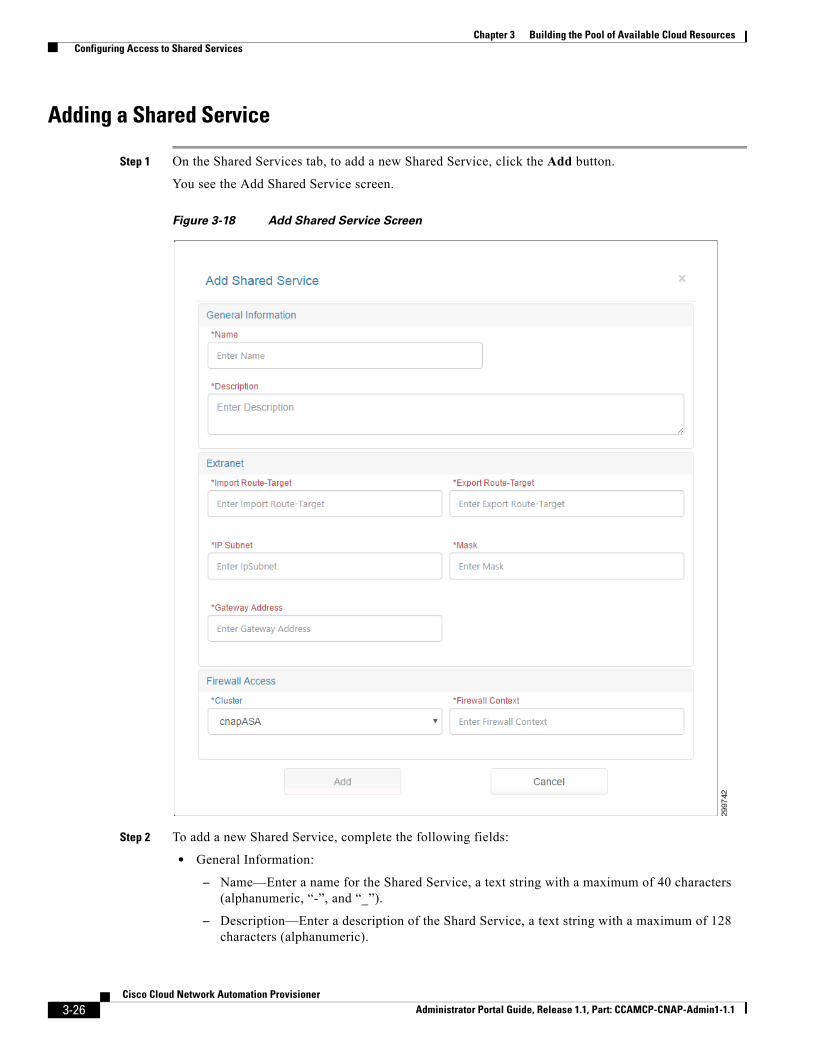
Figure 3-18 Add Shared Service Screen
Step 2 To add a new Shared Service, complete the following fields:
• General Information:
– Name—Enter a name for the Shared Service, a text string with a maximum of 40 characters (alphanumeric, “-”, and “_”).
– Description—Enter a description of the Shard Service, a text string with a maximum of 128 characters (alphanumeric).
3-26Cisco Cloud Network Automation Provisioner
Administrator Portal Guide, Release 1.1, Part: CCAMCP-CNAP-Admin1-1.1

Chapter 3 Building the Pool of Available Cloud Resources Configuring Access to Shared Services
• Extranet:
– Import Route-Target—Text String in the format: <number>:<number>; e.g., 99:999. Import Route Target on the MPLS Network through which the Shared Service is accessible.
– Export Route-Target—Text String in the format: <number>:<number>; e.g., 99:999. Export Route Target on the MPLS Network through which the Shared Service is accessible.
– IP Subnet—IP subnet (Public) in dotted format: A.B.C.D.
– Mask—Subnet Mask associated with the Shared Service subnet using the CIDR Notation: /<number>; e.g., /32.
• Gateway Address—Provider Edge (PE) gateway address in dotted format: A.B.C.D.
Note If you are using Shared Services with PE manual provisioning (VLAN hand-off mode), the gateway address is the inside interface of the shared service firewall context that connects to the outside interface of the Value Added Service (VAS) firewall context.
• Firewall Access:
– Cluster—List of the names of all Cisco ASA Firewall devices (DeviceType= ASA5585) registered in Cisco CNAP using the Network Devices tab. If no Cisco ASA devices have been registered, you see a message to onboard a new Cisco ASA device.
– Context—Text string with a maximum of 32 characters. The name of the firewall context defined in the Cisco ASA to handle the Shared Service.
Step 3 When you are finished, click Add.
The new Shared Service is shown on the Shared Services tab.
Changing a Shared Service
Note If the Shared Service has containers that have activated the service or the Shared Service is configured in a Cisco CNAP container plan, you cannot change it.
Step 1 To change a Shared Service, on the Shared Services tab, click the service you want to change to highlight it, then click Change.
If the Shared Service is configured in a plan or has active subscribers using the service, you see one of the following screens.
3-27Cisco Cloud Network Automation Provisioner
Administrator Portal Guide, Release 1.1, Part: CCAMCP-CNAP-Admin1-1.1

Chapter 3 Building the Pool of Available Cloud Resources Configuring Access to Shared Services
Figure 3-19 Shared Service Denied Operation Screen—Configured in Plan
Figure 3-20 Shared Service Denied Operation Screen—Service has Subscriber
If the service can be modified, you see the Add Shared Service screen with information about the existing Shared Service you selected.
3-28Cisco Cloud Network Automation Provisioner
Administrator Portal Guide, Release 1.1, Part: CCAMCP-CNAP-Admin1-1.1

Chapter 3 Building the Pool of Available Cloud Resources Configuring Access to Shared Services
Figure 3-21 Add Shared Service Screen—Modify Existing Information
Step 2 To change the Shared Service, modify the fields you want to change:
• General Information:
– Name—Enter a name for the Shared Service, a text string with a maximum of 40 characters.
– Description—Enter a description of the Shard Service, a text string with a maximum of 128 characters.
• Extranet:
Note If VLAN handoff is being used for Shared Services, the Extranet Route Targets are ignored.
3-29Cisco Cloud Network Automation Provisioner
Administrator Portal Guide, Release 1.1, Part: CCAMCP-CNAP-Admin1-1.1
Chapter 3 Building the Pool of Available Cloud Resources Configuring Access to Shared Services
– Import Route-Target—Text String in the format: <number>:<number>; e.g., 99:999. Import Route Target on the MPLS Network through which the Shared Service is accessible.
– Export Route-Target—Text String in the format: <number>:<number>; e.g., 99:999. Export Route Target on the MPLS Network through which the Shared Service is accessible.
– IP Subnet—IP subnet (Public) in dotted format: A.B.C.D.
– Mask—Subnet Mask associated with the Shared Service subnet using the CDIR Notation: /<number>; e.g., /32.
• Firewall Access:
– Cluster—List of the names of all Cisco ASA Firewall devices (DeviceType= ASA) registered in Cisco CNAP using the Cisco CNAP Network Devices tab. If no Cisco ASA devices have been registered, you see a message to onboard a new Cisco ASA device.
– Context—Text string with a maximum of 32 characters. The name of the firewall context defined in the Cisco ASA to handle the Shared Service.
Step 3 When you are finished, click Change.
Removing a Shared Service
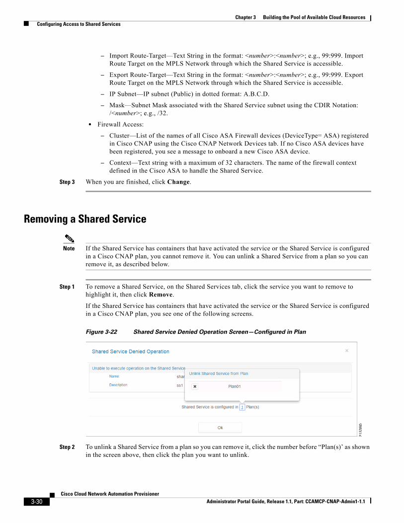
Note If the Shared Service has containers that have activated the service or the Shared Service is configured in a Cisco CNAP plan, you cannot remove it. You can unlink a Shared Service from a plan so you can remove it, as described below.
Step 1 To remove a Shared Service, on the Shared Services tab, click the service you want to remove to highlight it, then click Remove.
If the Shared Service has containers that have activated the service or the Shared Service is configured in a Cisco CNAP plan, you see one of the following screens.
Figure 3-22 Shared Service Denied Operation Screen—Configured in Plan
Step 2 To unlink a Shared Service from a plan so you can remove it, click the number before “Plan(s)’ as shown in the screen above, then click the plan you want to unlink.
3-30Cisco Cloud Network Automation Provisioner
Administrator Portal Guide, Release 1.1, Part: CCAMCP-CNAP-Admin1-1.1

Chapter 3 Building the Pool of Available Cloud Resources Configuring Access to Shared Services
Figure 3-23 Shared Service Denied Operation Screen—Service has Subscriber
If the Shared Service can be removed, you see the Remove Shared Service screen.
Figure 3-24 Remove Shared Service Screen
Step 3 To confirm the deletion, click Yes.
3-31Cisco Cloud Network Automation Provisioner
Administrator Portal Guide, Release 1.1, Part: CCAMCP-CNAP-Admin1-1.1
Chapter 3 Building the Pool of Available Cloud Resources Configuring Access to Shared Services
3-32Cisco Cloud Network Automation Provisioner
Administrator Portal Guide, Release 1.1, Part: CCAMCP-CNAP-Admin1-1.1