building timber-framed houses to resist wind documents/design_guide_40... · 40 technical design...
TRANSCRIPT
40
Technical Design Guide issued by Forest and Wood Products Australia
Building Timber-framed Houses to Resist Wind
WoodSolutions is an industry initiative designed to provide independent, non-proprietary information about timber and wood products to professionals and companies involved in building design and construction.
WoodSolutions is resourced by Forest and Wood Products Australia (FWPA – www.fwpa.com.au). It is a collaborative effort between FWPA members and levy payers, supported by industry bodies and technical associations.
This work is supported by funding provided to FWPA by the Commonwealth Government.
ISBN 978-1-925213-42-3
Prepared by: TimberED Services Pty Ltd Geoff Boughton Debbie Falck
Acknowledgements Author: Dr Geoff Boughton
Reviewed by: Colin MacKenzie (Technical consultant)
First Published: December 2016
© 2016 Forest and Wood Products Australia Limited. All rights reserved.
These materials are published under the brand WoodSolutions by FWPA.
IMPORTANT NOTICE
While all care has been taken to ensure the accuracy of the information contained in this publication, Forest and Wood Products Australia Limited (FWPA) and WoodSolutions Australia and all persons associated with them as well as any other contributors make no representations or give any warranty regarding the use, suitability, validity, accuracy, completeness, currency or reliability of the information, including any opinion or advice, contained in this publication. To the maximum extent permitted by law, FWPA disclaims all warranties of any kind, whether express or implied, including but not limited to any warranty that the information is up-to-date, complete, true, legally compliant, accurate, non-misleading or suitable.
To the maximum extent permitted by law, FWPA excludes all liability in contract, tort (including negligence), or otherwise for any injury, loss or damage whatsoever (whether direct, indirect, special or consequential) arising out of or in connection with use or reliance on this publication (and any information, opinions or advice therein) and whether caused by any errors, defects, omissions or misrepresentations in this publication. Individual requirements may vary from those discussed in this publication and you are advised to check with State authorities to ensure building compliance as well as make your own professional assessment of the relevant applicable laws and Standards.
The work is copyright and protected under the terms of the Copyright Act 1968 (Cwth). All material may be reproduced in whole or in part, provided that it is not sold or used for commercial benefit and its source (Forest and Wood Products Australia Limited) is acknowledged and the above disclaimer is included. Reproduction or copying for other purposes, which is strictly reserved only for the owner or licensee of copyright under the Copyright Act, is prohibited without the prior written consent of FWPA.
WoodSolutions Australia is a registered business division of Forest and Wood Products Australia Limited.
WoodSolutions Technical Design Guides
A growing suite of information, technical and training resources, the Design Guides have been created to support the use of wood in the design and construction of the built environment.
Each title has been written by experts in the field and is the accumulated result of years of experience in working with wood and wood products.
Some of the popular topics covered by the Technical Design Guides include:
• Timber-framed construction• Building with timber in bushfire-prone areas• Designing for durability• Timber finishes• Stairs, balustrades and handrails• Timber flooring and decking• Timber windows and doors• Fire compliance• Acoustics• Thermal performance
More WoodSolutions Resources
The WoodSolutions website provides a comprehensive range of resources for architects, building designers, engineers and other design and construction professionals.
To discover more, please visit www.woodsolutions.com.au The website for wood.
01
Technical Design Guide issued by Forest and Wood Products Australia
Timber-framed Constructionfor Townhouse Buildings Class 1aDesign and construction guide for BCA compliant sound and fire-rated construction
04
Technical Design Guide issued by Forest and Wood Products Australia
Building with Timber in Bushfire-prone AreasBCA Compliant Design and Construction Guide
09
Technical Design Guide issued by Forest and Wood Products Australia
Timber FlooringDesign guide for installation
Cover image: Beach House - Mornington, Clare Cousins Architects Photography: Shannon McGrath
Page 3Guide 40 • Building Timber-framed Houses to Resist Wind
1 Introduction 5
1.1 Scope ............................................................................................................................................................... 5
1.2 How to Use this Guide ...................................................................................................................................... 6
2 Building Codes and Standards 7
2.1 National Construction Code and Building Code of Australia .............................................................................. 7
2.2 Standards Used to Determine Wind Loads ........................................................................................................ 8
2.3 Residential Timber-framed Construction Standards ......................................................................................... 11
2.4 Residential Timber-framed Construction .......................................................................................................... 12
3 Wind Effects on Buildings 14
3.1 Pressure on Windward Walls ........................................................................................................................... 14
3.2 Internal Pressures ............................................................................................................................................ 15
3.3 Uplift on External Surfaces .............................................................................................................................. 16
3.4 Bracing Loads ................................................................................................................................................. 16
3.5 Design to Resist Wind Effects.......................................................................................................................... 17
4 Site Wind Classification 18
4.1 AS 4055 – Wind Loads for Housing ................................................................................................................ 18
4.2 AS/NZS 1170.2 ............................................................................................................................................... 26
5 Tie-downs 27
5.1 Corrosion Protection of Tie-down Connections ............................................................................................... 28
5.2 General, Edge and Corner Areas of Roofs ....................................................................................................... 29
5.3 Roof Cladding to Battens ................................................................................................................................ 29
5.4 Roof Members ................................................................................................................................................ 31
5.5 Connections between Structural Roof Members ............................................................................................. 31
5.6 Tie-down through Roof Structure to Walls ....................................................................................................... 34
5.7 Tie-down of Walls ............................................................................................................................................ 35
6 Bracing Houses to Resist Lateral Forces 36
6.1 Principles of Bracing in Houses ....................................................................................................................... 36
6.2 Calculation of Bracing Wall Requirements........................................................................................................ 38
6.3 Calculation of Bracing Resistance of the Walls ................................................................................................ 41
6.4 Connections for Bracing Walls ......................................................................................................................... 43
6.5 Temporary Bracing during Construction .......................................................................................................... 43
7 Construction of New Houses 44
7.1 Compliance to BCA ........................................................................................................................................ 44
7.2 Wind Classification .......................................................................................................................................... 44
7.3 Timber Framing ............................................................................................................................................... 44
7.4 Internal Pressure ............................................................................................................................................. 44
7.5 Installation of Windows and Doors .................................................................................................................. 45
7.6 Installation of Garage Doors ............................................................................................................................ 47
7.7 Tie-down of Stick-built Roofs to Masonry Walls ............................................................................................... 47
Contents
Page 4Guide 40 • Building Timber-framed Houses to Resist Wind
Contents
8 Tie-downs in Existing Houses 50
8.1 Replacing Roof Cladding and Other Renovations ............................................................................................ 50
8.2 Additions and Extensions ................................................................................................................................ 50
8.3 Repairs following Damage from Wind Events .................................................................................................. 51
References 53
Australian Standards ..................................................................................................................................................... 54
WoodSolutions Publications .......................................................................................................................................... 55
Additional Resources ..................................................................................................................................................... 55
Page 5Guide 40 • Building Timber-framed Houses to Resist Wind
Contents
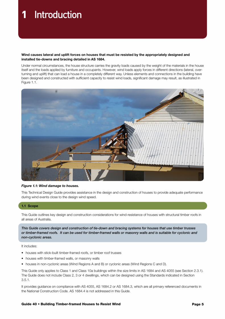
Wind causes lateral and uplift forces on houses that must be resisted by the appropriately designed and installed tie-downs and bracing detailed in AS 1684.
Under normal circumstances, the house structure carries the gravity loads caused by the weight of the materials in the house itself and the loads applied by furniture and occupants. However, wind loads apply forces in different directions (lateral, over-turning and uplift) that can load a house in a completely different way. Unless elements and connections in the building have been designed and constructed with sufficient capacity to resist wind loads, significant damage may result, as illustrated in Figure 1.1.
Figure 1.1: Wind damage to houses.
This Technical Design Guide provides assistance in the design and construction of houses to provide adequate performance during wind events close to the design wind speed.
1.1 Scope
This Guide outlines key design and construction considerations for wind-resistance of houses with structural timber roofs in all areas of Australia.
This Guide covers design and construction of tie-down and bracing systems for houses that use timber trusses or timber-framed roofs. It can be used for timber-framed walls or masonry walls and is suitable for cyclonic and non-cyclonic areas.
It includes:
• houses with stick-built timber-framed roofs, or timber roof trusses
• houses with timber-framed walls, or masonry walls
• houses in non-cyclonic areas (Wind Regions A and B) or cyclonic areas (Wind Regions C and D).
This Guide only applies to Class 1 and Class 10a buildings within the size limits in AS 1684 and AS 4055 (see Section 2.3.1). The Guide does not include Class 2, 3 or 4 dwellings, which can be designed using the Standards indicated in Section 3.5.1.
It provides guidance on compliance with AS 4055, AS 1684.2 or AS 1684.3, which are all primary referenced documents in the National Construction Code. AS 1684.4 is not addressed in this Guide.
1 Introduction
Page 6Guide 40 • Building Timber-framed Houses to Resist Wind
Some states may have additional regulatory requirements for timber-framed construction, which are published as state or territory variations in the National Construction Code (NCC) or via other state or territory Acts and Codes.
1.2 How to Use this Guide
1.2.1 Outline of the Guide
Section 2 contains background on the Codes and Standards used in designing houses and Section 3 contains background on wind loads on houses. These sections provide the context for the other sections in this Guide.
Section 4 provides guidance for determining the wind classification for a house. Even if someone else has responsibility for the evaluation of the wind classification, make sure you understand how it is selected, and develop a ‘feel’ for what is a sensible classification for each site. Determining the correct site wind classification is essential to ensure every house has the appropriate details to resist the wind loads.
Section 5 gives guidance on selecting the correct tie-down connections for the house. The tie-downs form a chain of strength from the roof cladding to the ground.
Section 6 gives guidance on evaluating bracing loads and capacity in the two principle directions – parallel and perpendicular to the main ridgeline.
Section 7 contains advice for selecting elements to resist wind in new houses. It covers structural framing elements such as rafters or trusses and connections, and provides some guidance on envelope elements such as windows and garage doors. It cross-references Sections 4, 5 and 6.
Section 8 contains useful information for planning repairs or renovations so that the resilience of the house to wind actions is improved. It also cross-references Sections 4, 5 and 6.
1.2.2 Other Documents
It is not possible to design for wind resistance using this Guide alone, but it explains the steps required to design and build houses that comply with relevant Codes and Standards.
This Guide is used in conjunction with AS 1684.2, AS 1684.3 and AS 4055.
To understand this Design Guide, it is essential to have access to copies of AS 1684 (Parts 2 or 3) and AS 4055.
This Guide is part of a suite of WoodSolutions resources, including Technical Guides and AS 1684 User Guides. Other appropriate resources to assist with the use of AS 1684 are listed in the References section.
Page 7Guide 40 • Building Timber-framed Houses to Resist Wind
Contents
2.1 National Construction Code and Building Code of Australia
All buildings must comply with the National Construction Code (NCC); Volume 1 for most buildings, and Volume 2 for houses only (Class 1 and class 10a). Volumes 1 and 2 of the NCC are the Building Code of Australia (BCA). Volume 3 of the NCC concerns plumbing and is not referred to in this Guide. Any reference to the BCA in this Guide includes the NCC.
AS 4055 and AS 1684.2 or AS 1684.3 are acceptable construction manuals and are used to design most houses in Australia.
The BCA provides Deemed-to-Satisfy provisions that reference Australian Standards and other documents. It represents a minimum standard for construction. In some cases, owners may want higher levels of performance than the minimum set out in the BCA.
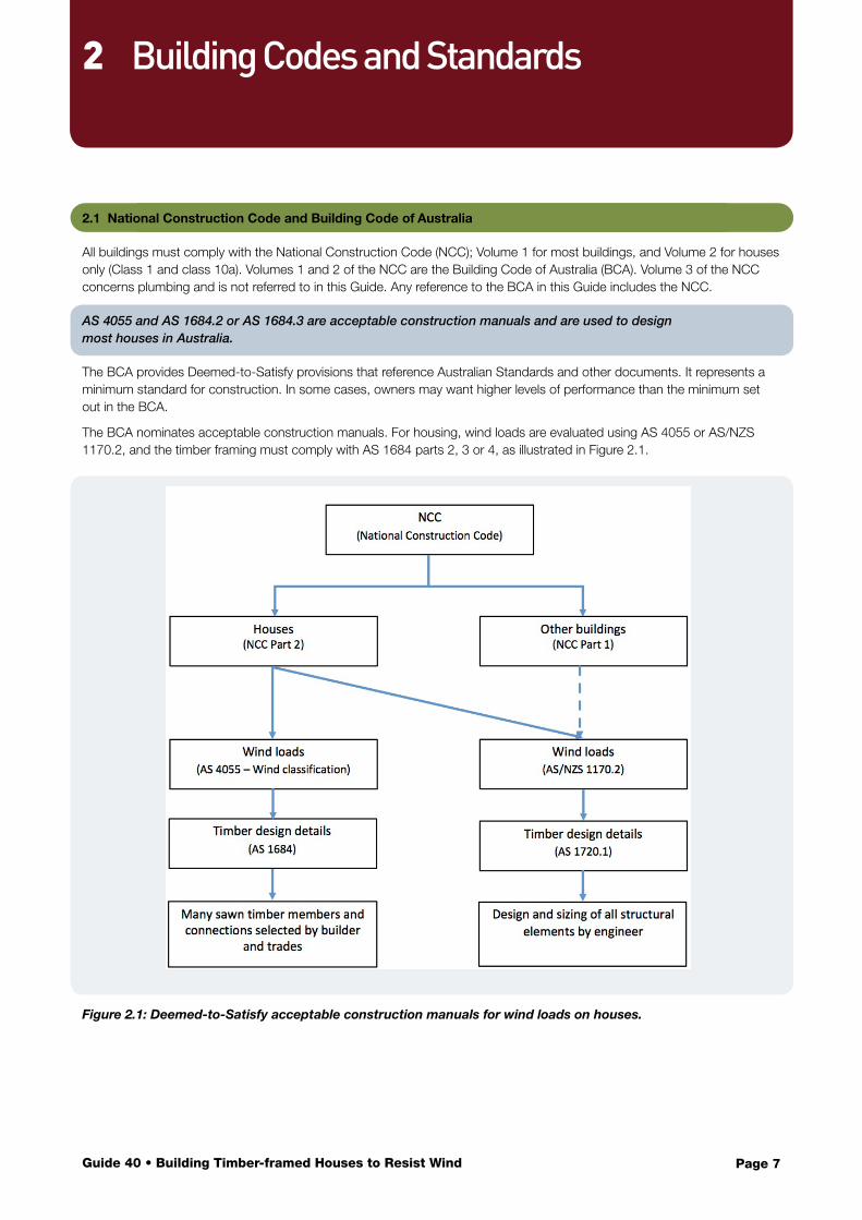
The BCA nominates acceptable construction manuals. For housing, wind loads are evaluated using AS 4055 or AS/NZS 1170.2, and the timber framing must comply with AS 1684 parts 2, 3 or 4, as illustrated in Figure 2.1.
Figure 2.1: Deemed-to-Satisfy acceptable construction manuals for wind loads on houses.
2 Building Codes and Standards
Page 8Guide 40 • Building Timber-framed Houses to Resist Wind
The BCA’s objectives relevant to wind loads are to:
• safeguard people from injury caused by structural failure• safeguard people from loss of amenity caused by structural failure• protect other property from physical damage caused by structural failure• safeguard people from injury that may be caused by failure of, or debris impact with, glazing.
To meet these objectives, the building must:
• remain stable and not collapse• prevent failure from progressing following minor damage• minimise loss of amenity• avoid causing damage to other properties.
The BCA requires all buildings to protect occupants by remaining stable, preventing failures, and avoiding loss of amenity and damage to other buildings.
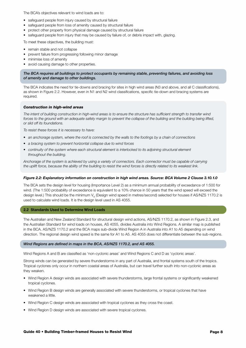
The BCA indicates the need for tie-downs and bracing for sites in high wind areas (N3 and above, and all C classifications), as shown in Figure 2.2. However, even in N1 and N2 wind classifications, specific tie-down and bracing systems are required.
Figure 2.2: Explanatory information on construction in high wind areas. Source: BCA Volume 2 Clause 3.10.1.0
The BCA sets the design level for housing (Importance Level 2) as a minimum annual probability of exceedance of 1:500 for wind. (The 1:500 probability of exceedance is equivalent to a 10% chance in 50 years that the wind speed will exceed the design level.) This should be the minimum VR (Design wind speed in metres/second) selected for houses if AS/NZS 1170.2 is used to calculate wind loads. It is the design level used in AS 4055.
2.2 Standards Used to Determine Wind Loads
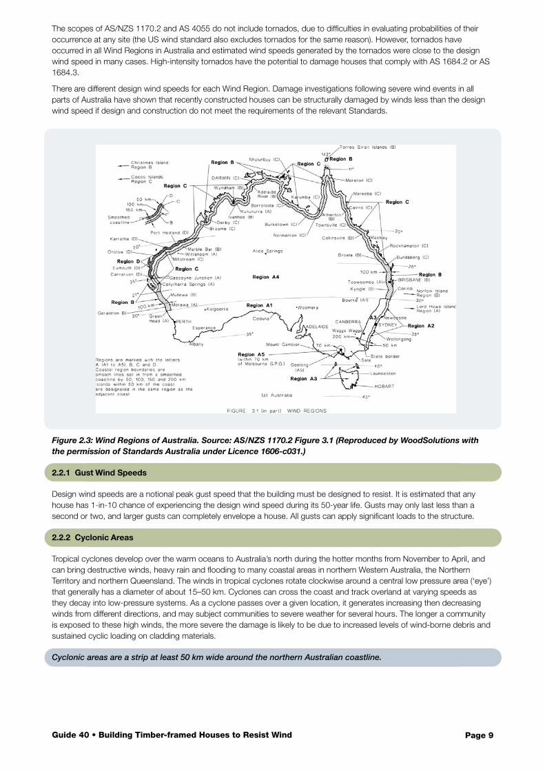
The Australian and New Zealand Standard for structural design wind actions, AS/NZS 1170.2, as shown in Figure 2.3, and the Australian Standard for wind loads on houses, AS 4055, divides Australia into Wind Regions. A similar map is published in the BCA. AS/NZS 1170.2 and the BCA maps sub-divide Wind Region A in Australia into A1 to A5 depending on wind direction. The regional design wind speed is the same for A1 to A5. AS 4055 does not differentiate between the sub-regions.
Wind Regions are defined in maps in the BCA, AS/NZS 1170.2, and AS 4055.
Wind Regions A and B are classified as ‘non-cyclonic areas’ and Wind Regions C and D as ‘cyclonic areas’.
Strong winds can be generated by severe thunderstorms in any part of Australia, and frontal systems south of the tropics. Tropical cyclones only occur in northern coastal areas of Australia, but can travel further south into non-cyclonic areas as they weaken.
• Wind Region A design winds are associated with severe thunderstorms, large frontal systems or significantly weakened tropical cyclones.
• Wind Region B design winds are generally associated with severe thunderstorms, or tropical cyclones that have weakened a little.
• Wind Region C design winds are associated with tropical cyclones as they cross the coast.
• Wind Region D design winds are associated with severe tropical cyclones.
Construction in high-wind areas
The intent of building construction in high-wind areas is to ensure the structure has sufficient strength to transfer wind forces to the ground with an adequate safety margin to prevent the collapse of the building and the building being lifted, or slid off its foundations.
To resist these forces it is necessary to have:
• an anchorage system, where the roof is connected by the walls to the footings by a chain of connections
• a bracing system to prevent horizontal collapse due to wind forces
• continuity of the system where each structural element is interlocked to its adjoining structural element throughout the building.
Anchorage of the system is achieved by using a variety of connectors. Each connector must be capable of carrying the uplift force, because the ability of the building to resist the wind forces is directly related to its weakest link.
Page 9Guide 40 • Building Timber-framed Houses to Resist Wind
The scopes of AS/NZS 1170.2 and AS 4055 do not include tornados, due to difficulties in evaluating probabilities of their occurrence at any site (the US wind standard also excludes tornados for the same reason). However, tornados have occurred in all Wind Regions in Australia and estimated wind speeds generated by the tornados were close to the design wind speed in many cases. High-intensity tornados have the potential to damage houses that comply with AS 1684.2 or AS 1684.3.
There are different design wind speeds for each Wind Region. Damage investigations following severe wind events in all parts of Australia have shown that recently constructed houses can be structurally damaged by winds less than the design wind speed if design and construction do not meet the requirements of the relevant Standards.
Figure 2.3: Wind Regions of Australia. Source: AS/NZS 1170.2 Figure 3.1 (Reproduced by WoodSolutions with the permission of Standards Australia under Licence 1606-c031.)
2.2.1 Gust Wind Speeds
Design wind speeds are a notional peak gust speed that the building must be designed to resist. It is estimated that any house has 1-in-10 chance of experiencing the design wind speed during its 50-year life. Gusts may only last less than a second or two, and larger gusts can completely envelope a house. All gusts can apply significant loads to the structure.
2.2.2 Cyclonic Areas
Tropical cyclones develop over the warm oceans to Australia’s north during the hotter months from November to April, and can bring destructive winds, heavy rain and flooding to many coastal areas in northern Western Australia, the Northern Territory and northern Queensland. The winds in tropical cyclones rotate clockwise around a central low pressure area (‘eye’) that generally has a diameter of about 15–50 km. Cyclones can cross the coast and track overland at varying speeds as they decay into low-pressure systems. As a cyclone passes over a given location, it generates increasing then decreasing winds from different directions, and may subject communities to severe weather for several hours. The longer a community is exposed to these high winds, the more severe the damage is likely to be due to increased levels of wind-borne debris and sustained cyclic loading on cladding materials.
Cyclonic areas are a strip at least 50 km wide around the northern Australian coastline.
Page 10Guide 40 • Building Timber-framed Houses to Resist Wind
Tropical cyclones are usually hundreds of kilometres wide, can travel hundreds of kilometres and can affect an area of hundreds of square kilometres. The highest winds are experienced just outside the eye, and the peak gust speed decreases with distance from the edge of the eye. The Bureau of Meteorology categorises cyclones as shown in Table 2.1 with increasing severity from Category 1 to 5 according to the maximum expected gust wind speed near the centre of the cyclone.
Table 2.1: Bureau of Meteorology Cyclone Categories.
Cyclone Category
Gust Wind Speed near the centre of the cyclone at 10 m height in flat open terrain
Bottom of wind speed range is within the design wind speed
Wind Regionskm/h Knots m/s
1 90–125 49–68 25–35 A, B, C, D
2 125–164 68–89 35–46 A, B, C, D
3 165–224 89–121 46–62 B, C, D
4 225–279 121–151 62–78 C, D
5 >280 >151 >78 D
For example, a Category 4 tropical cyclone crossing the coast may cause wind speeds near the centre that are close to the design wind speed for Wind Region C housing. At that time, the winds will be significantly lower for houses that are around 50 km from the centre, which may experience winds equivalent to a Category 3 event. The winds even further from the centre will be the equivalent of a Category 2 event or, hundreds of kilometres away, a Category 1 event.
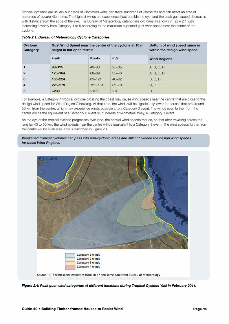
As the eye of the tropical cyclone progresses over land, the central wind speeds reduce, so that after travelling across the land for 40 to 50 km, the wind speeds near the centre will be equivalent to a Category 3 event. The wind speeds further from the centre will be even less. This is illustrated in Figure 2.4
Weakened tropical cyclones can pass into non-cyclonic areas and still not exceed the design wind speeds for those Wind Regions.
Figure 2.4: Peak gust wind categories at different locations during Tropical Cyclone Yasi in February 2011.
Page 11Guide 40 • Building Timber-framed Houses to Resist Wind
2.2.3 Non-cyclonic Areas
The design wind event in Wind Regions A and B is usually associated with a localised frontal weather system or severe thunderstorm, both of which typically last for less than an hour. Designers and builders should not underestimate the damage that even 120 km/h winds can inflict on houses with inadequate roof connections in these Wind Regions.
Weakened tropical cyclones often pass through Wind Regions B and A. Table 2.1 shows that houses in Wind Regions A and B are designed to resist wind speeds greater than those in Category 1 and most Category 2 tropical cyclones.
2.2.4 AS/NZS 1170.2 Structural Design Actions – Part 2: Wind Actions
This Standard is the primary wind loading Standard for Australia and New Zealand. It is a referenced document in the BCA and can be used by engineers to select wind loads for any structural members on buildings (see Section 3.5.1). If this Standard is used to evaluate wind loads on buildings, a wind classification (e.g. N1 or C2) is not given.
2.2.5 AS 4055 Wind Loads for Housing
This Standard is a simplified wind loading Standard restricted for use with houses. It is compatible with AS/NZS 1170.2 and gives similar wind load effects to AS/NZS 1170.2. Both AS 4055 and AS/NZS 1170.2 use the same Wind Regions shown in Figure 2.3. Either Standard can be used to select wind loads on houses. AS 1684 uses wind classifications consistent with AS 4055.
AS 4055 is compatible with AS/NZS 1170.2, but uses simplified calculations and is only suitable for design of houses.
AS 4055 presents methods for:
• evaluating the wind classification to be used in the design and construction of a house• calculating wind pressures on elements such as roofing, windows and wall cladding• determining the tie-down forces at the top of walls• evaluating racking loads to be resisted by bracing elements in the house.
The first two of these steps are detailed in Section 4, and the other two are presented in Section 5 and Section 6, respectively.
2.3 Residential Timber-framed Construction Standards
Australia has a suite of Standards that support the design and construction of timber-framed houses. Each contains:
• building practice notes on arrangements of members, connection methods and geometric limits• information on determining member sizes using span tables, the building plans, timber grade and wind classification• methods for calculating bracing loads on the house and establishing the bracing resistance of the walls in the house• tie-down requirements for all structural elements on the load path between the roof cladding and the ground.
AS 1684 is a suite of Standards that provides comprehensive specifications for the design of timber-framed housing.
2.3.1 Geometric Limitations
AS 1684 and AS 4055 have geometric limitations on houses that can be designed using these documents. These limitations ensure that the simplifying assumptions that enable the use of the deemed-to-satisfy construction manuals on the left hand path in Figure 2.1 are valid. If any house does not fall within these limitations, it must be designed using AS/NZS 1170.2 and AS 1720.1, as shown in the right hand path in Figure 2.1.
AS 1684 and AS 4055 can only be used to design houses within size and height limitations.
Limitations on the use of AS 4055 and AS 1684 include:
• maximum number of storeys anywhere in the building = two• maximum wall height under floors or under the lowest point of the ceiling = 3 m• maximum distance between external walls across a ridge line or under a skillion roof = 16 m• maximum distance between any two bracing walls in the same direction = 9 m• maximum roof slope = 35°.
2.3.2 AS 1684.2 Non-cyclonic Areas
This volume contains the information needed for design and construction of houses in Wind Regions A and B. The format of AS 1684.2 and its span table supplements is similar to that of AS 1684.3.
Page 12Guide 40 • Building Timber-framed Houses to Resist Wind
2.3.3 AS 1684.3 Cyclonic Areas
This volume contains the information needed for design and construction of houses in Wind Regions C and D. The higher wind speeds in these regions mean that the tie-downs and bracing must have higher capacity than those in Wind Regions A and B. The format of AS 1684.3 and its span table supplements is similar to that of AS 1684.2. AS 1684.3 only provides design solutions for wind classifications up to C3. Higher wind classifications are possible and will need to be engineer-designed and certified using AS/NZS 1170.2 and AS 1720.1, as shown in the right-hand compliance path in Figure 2.1.
2.3.4 AS 1684.4 Simplified – Non-cyclonic Areas
This document is applicable to houses with N1 or N2 classifications only. It is set out differently to the other parts of AS 1684 and has span tables in a different format. Because this part is restricted to very low-wind classifications, it has simplified tie-downs and bracing details. AS 1684.4 is not addressed in this Design Guide.
This Design Guide does not include the use of AS 1684.4.
2.4 Residential Timber-framed Construction
2.4.1 Different Construction Methods
Houses can be designed and constructed using a variety of different combinations of cladding and structural elements. Different Standards apply to different construction methods and materials:
• Timber floor frame, timber wall frames and timber-framed roof – AS 1684 applies.
• Timber floor cassette system, timber wall frames and timber-framed roof – AS 1684 applies to the wall and roof frames. Cassette floor manufacturers provide details on the floor system.
• Concrete slab, timber wall frames and timber-framed roof – AS 1684 applies to the wall frames and roof frames. Forces in tie-downs to the slab can be calculated using AS 1684.
• Concrete slab, solid masonry walls and timber-framed roof – AS 1684 applies to the roof frames only. Forces in tie-downs from the roof to the walls can be calculated using AS 1684.
• Timber floor frame, timber wall frames and timber-trussed roof – AS 1684 applies to all but the trusses (use AS 1720.5 and AS 4440 for the trusses).
• Concrete slab, timber wall frames and timber-trussed roof – AS 1684 applies to wall frames. Forces in tie-downs to the slab can be calculated using AS 1684. Use AS 1720.5 and AS 4440 for the trusses.
• Concrete slab, masonry walls and timber-trussed roof – AS 1684 does not apply. Use AS 1720.5 and AS 4440 for the trusses.
Lightweight timber-framed construction systems can be prefabricated off-site into wall frames, floor and roof trusses, or cassette floor modules, and then erected on-site. AS 1684 applies to timber wall frames and tie-down and bracing requirements for the whole house. AS 1720.5 and AS 4440 provide requirements for trusses.
2.4.2 Timber Materials
A number of different sawn and manufactured timber products are used in timber-framed house construction.
Sawn timber products
Sawn timber products include seasoned structural softwood (MGP10 and MGP12 with limited amounts of MGP15 available) and seasoned or unseasoned structural hardwood (typically F8 to F27 or A17). Commonly used thicknesses are 35 mm and 45mm for seasoned timber, and 38 mm, 50 mm and 75 mm for unseasoned timber.
AS 1684 includes span tables and construction practices that are based on commonly available stress-graded sawn timber.
Other timber materials used in domestic construction are shown in Figure 2.5.
AS 1684 span tables only include sawn timber products. Manufacturers of engineered wood products provide design support for their products.
Page 13Guide 40 • Building Timber-framed Houses to Resist Wind
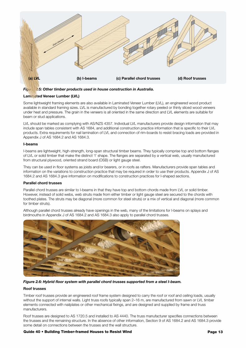
Figure 2.5: Other timber products used in house construction in Australia.
Laminated Veneer Lumber (LVL)
Some lightweight framing elements are also available in Laminated Veneer Lumber (LVL), an engineered wood product available in standard framing sizes. LVL is manufactured by bonding together rotary peeled or thinly sliced wood veneers under heat and pressure. The grain in the veneers is all oriented in the same direction and LVL elements are suitable for beam or stud applications.
LVL should be marked as complying with AS/NZS 4357. Individual LVL manufacturers provide design information that may include span tables consistent with AS 1684, and additional construction practice information that is specific to their LVL products. Extra requirements for nail lamination of LVL and connection of rim-boards to resist bracing loads are provided in Appendix J of AS 1684.2 and AS 1684.3.
I-beams
I-beams are lightweight, high-strength, long-span structural timber beams. They typically comprise top and bottom flanges of LVL or solid timber that make the distinct ‘I’ shape. The flanges are separated by a vertical web, usually manufactured from structural plywood, oriented strand board (OSB) or light gauge steel.
They can be used in floor systems as joists and/or bearers, or in roofs as rafters. Manufacturers provide span tables and information on the variations to construction practice that may be required in order to use their products. Appendix J of AS 1684.2 and AS 1684.3 give information on modifications to construction practices for I-shaped sections.
Parallel chord trusses
Parallel chord trusses are similar to I-beams in that they have top and bottom chords made from LVL or solid timber. However, instead of solid webs, web struts made from either timber or light gauge steel are secured to the chords with toothed plates. The struts may be diagonal (more common for steel struts) or a mix of vertical and diagonal (more common for timber struts).
Although parallel chord trusses already have openings in the web, many of the limitations for I-beams on splays and birdmouths in Appendix J of AS 1684.2 and AS 1684.3 also apply to parallel chord trusses.
Figure 2.6: Hybrid floor system with parallel chord trusses supported from a steel I-beam.
Roof trusses
Timber roof trusses provide an engineered roof frame system designed to carry the roof or roof and ceiling loads, usually without the support of internal walls. Light truss roofs typically span 2–16 m, are manufactured from sawn or LVL timber elements connected with nailplates or other mechanical fixings, and are designed and supplied by frame and truss manufacturers.
Roof trusses are designed to AS 1720.5 and installed to AS 4440. The truss manufacturer specifies connections between the trusses and the remaining structure. In the absence of other information, Section 9 of AS 1684.2 and AS 1684.3 provide some detail on connections between the trusses and the wall structure.
Grain direction
(a) LVL (b) I-beams (c) Parallel chord trusses (d) Roof trusses
!
Page 14Guide 40 • Building Timber-framed Houses to Resist Wind
Contents
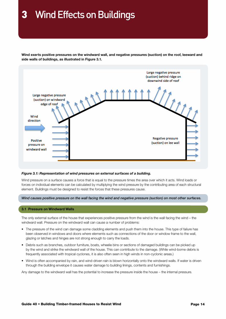
Wind exerts positive pressures on the windward wall, and negative pressures (suction) on the roof, leeward and side walls of buildings, as illustrated in Figure 3.1.
Figure 3.1: Representation of wind pressures on external surfaces of a building.
Wind pressure on a surface causes a force that is equal to the pressure times the area over which it acts. Wind loads or forces on individual elements can be calculated by multiplying the wind pressure by the contributing area of each structural element. Buildings must be designed to resist the forces that these pressures cause.
Wind causes positive pressure on the wall facing the wind and negative pressure (suction) on most other surfaces.
3.1 Pressure on Windward Walls
The only external surface of the house that experiences positive pressure from the wind is the wall facing the wind – the windward wall. Pressure on the windward wall can cause a number of problems:
• The pressure of the wind can damage some cladding elements and push them into the house. This type of failure has been observed in windows and doors where elements such as connections of the door or window frame to the wall, glazing or latches and hinges are not strong enough to carry the loads.
• Debris such as branches, outdoor furniture, boats, wheelie bins or sections of damaged buildings can be picked up by the wind and strike the windward wall of the house. This can contribute to the damage. (While wind-borne debris is frequently associated with tropical cyclones, it is also often seen in high winds in non-cyclonic areas.)
• Wind is often accompanied by rain, and wind-driven rain is blown horizontally onto the windward walls. If water is driven through the building envelope it causes water damage to building linings, contents and furnishings.
Any damage to the windward wall has the potential to increase the pressure inside the house – the internal pressure.
3 Wind Effects on Buildings
Page 15Guide 40 • Building Timber-framed Houses to Resist Wind
3.2 Internal Pressures
Figure 3.1 shows the pressures and suctions generated by the wind on the outside of the building. However, at the same time, there will also be positive or negative pressures on the inside of the house. These pressures are negative or positive depending on whether there are openings in the building envelope. Openings may be caused by:
• small gaps around doors and windows throughout the house• occupants leaving doors or windows open• wind pressure forcing a door, window or garage door open• wind-borne debris breaking cladding or glazing elements on the windward wall.
Where the openings are roughly the same on all walls (e.g. small gaps around all doors and windows, or if all of the windows are left open by the occupant), the internal pressures tend to be negative. This is because the majority of the building surfaces have negative external pressure (suction) on them, as shown in Figure 3.1.
Any opening in the building envelope will cause internal pressures that contribute to the loads on the structure.
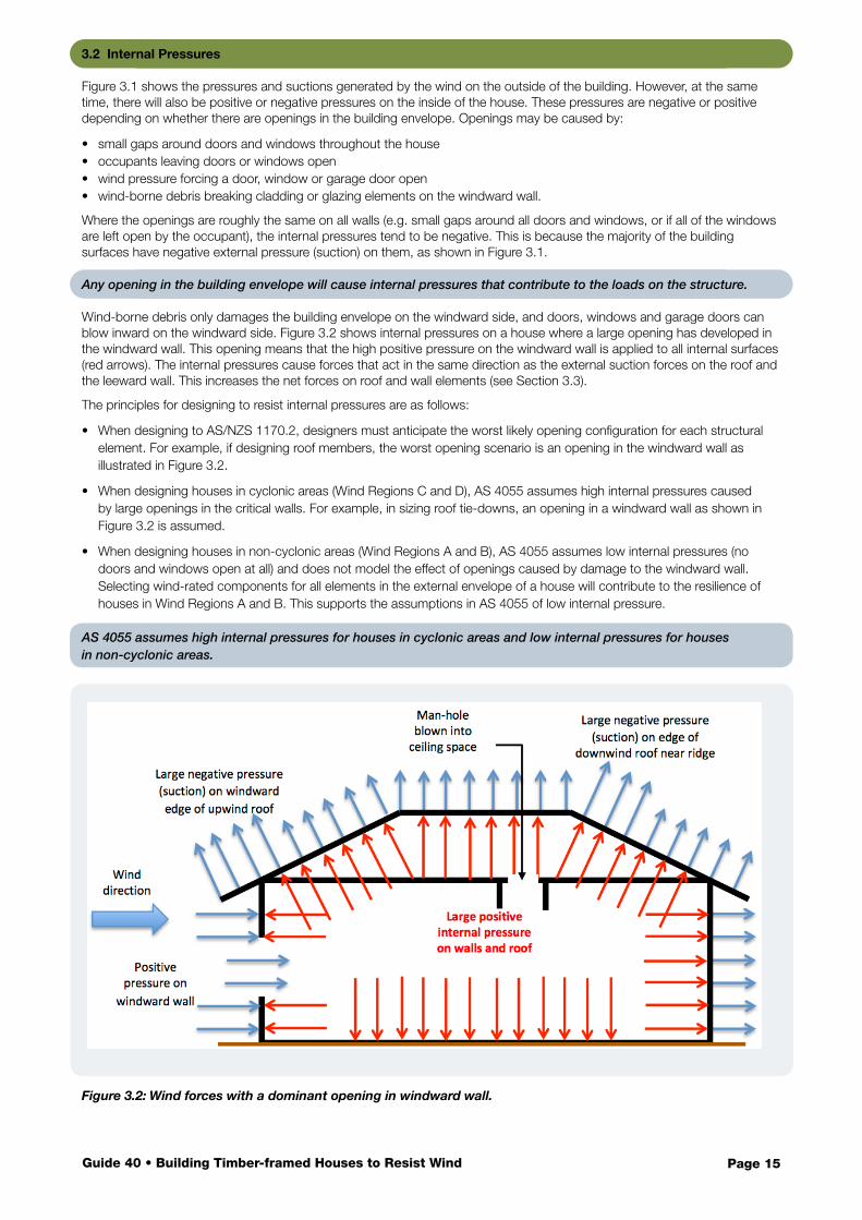
Wind-borne debris only damages the building envelope on the windward side, and doors, windows and garage doors can blow inward on the windward side. Figure 3.2 shows internal pressures on a house where a large opening has developed in the windward wall. This opening means that the high positive pressure on the windward wall is applied to all internal surfaces (red arrows). The internal pressures cause forces that act in the same direction as the external suction forces on the roof and the leeward wall. This increases the net forces on roof and wall elements (see Section 3.3).
The principles for designing to resist internal pressures are as follows:
• When designing to AS/NZS 1170.2, designers must anticipate the worst likely opening configuration for each structural element. For example, if designing roof members, the worst opening scenario is an opening in the windward wall as illustrated in Figure 3.2.
• When designing houses in cyclonic areas (Wind Regions C and D), AS 4055 assumes high internal pressures caused by large openings in the critical walls. For example, in sizing roof tie-downs, an opening in a windward wall as shown in Figure 3.2 is assumed.
• When designing houses in non-cyclonic areas (Wind Regions A and B), AS 4055 assumes low internal pressures (no doors and windows open at all) and does not model the effect of openings caused by damage to the windward wall. Selecting wind-rated components for all elements in the external envelope of a house will contribute to the resilience of houses in Wind Regions A and B. This supports the assumptions in AS 4055 of low internal pressure.
AS 4055 assumes high internal pressures for houses in cyclonic areas and low internal pressures for houses in non-cyclonic areas.
Figure 3.2: Wind forces with a dominant opening in windward wall.
Page 16Guide 40 • Building Timber-framed Houses to Resist Wind
3.3 Uplift on External Surfaces
All roofs (flat, pitched, hips, gables, simple or complex) experience wind uplift due to suctions created by the wind as it passes over the top of the roof surface. Figure 3.1 shows that the suctions on the roof create forces in an upward direction that tend to lift the roof off the walls. Figure 3.2 shows that an opening on the windward wall creates internal pressures acting in the same direction. The combination of positive internal pressure and external suction on roof surfaces can almost double the uplift loads on the roof. Many roof failures have been triggered by failure of elements on the windward wall of houses.
These upward forces can be large. For example, the lowest design wind speed for houses in AS 4055 produces a net upward force on a suburban house of 0.7 tonnes per 10 m2 of roof area. On other houses, the loads can be significantly more (e.g. up to 6.4 tonnes per 10 m2 of roof area for houses on hill tops in cyclone areas).
The upward forces from the wind exceed the weight of the materials in lightweight roofs, so tie-down systems are necessary to keep the roof on during high winds. The same is true for tiled roofs in many locations around Australia. The main cause of roof loss in strong wind events is inadequate connections between roof elements.
3.4 Bracing Loads
The combination of positive external pressures on the windward wall and negative pressures (suctions) on the opposite wall cause a net lateral force on the whole house. The blue arrows on the windward wall in Figure 3.1 and Figure 3.2 point to the right, and so do the blue arrows on the leeward or right hand wall. There is a net effect tending to push the whole house to the right. (Internal pressures act equally on windward and leeward walls and cancel each other out, i.e. internal pressures do not contribute to bracing loads.)
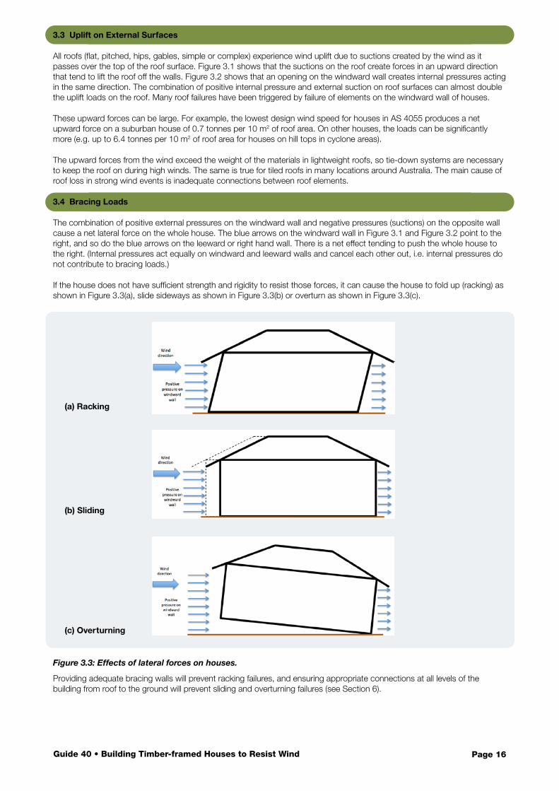
If the house does not have sufficient strength and rigidity to resist those forces, it can cause the house to fold up (racking) as shown in Figure 3.3(a), slide sideways as shown in Figure 3.3(b) or overturn as shown in Figure 3.3(c).
Figure 3.3: Effects of lateral forces on houses.
Providing adequate bracing walls will prevent racking failures, and ensuring appropriate connections at all levels of the building from roof to the ground will prevent sliding and overturning failures (see Section 6).
(a) Racking
(b) Sliding
(c) Overturning
Page 17Guide 40 • Building Timber-framed Houses to Resist Wind
3.5 Design to Resist Wind Effects
The process of designing to resist wind effects involves:
a) determining the design wind speed on the house
b) evaluating wind pressures on external and internal surfaces
c) calculating the tributary wind area for each structural element
d) calculating the wind force on each structural element
e) combining wind actions with other actions (self-weight, occupancy loads) on the element
f) selecting appropriate structural elements with sufficient capacity to resist the loads.
This is accomplished differently for the two design paths shown in Figure 2.1.
Designing to resist wind involves evaluating wind effects and loads, then detailing the structure to resist them.
3.5.1 AS/NZS 1170.2 and AS 1720.1
Structural engineers often use AS/NZS 1170.2 and AS 1720.1 to select and specify elements that have sufficient strength and stiffness to carry the required wind loads:
• AS/NZS 1170.2 is used to calculate the wind forces on each structural element used in Steps a) to d) in Section 3.5.
• AS/NZS 1170.0 is used to combine wind loads with other actions for Step e).
• AS 1720.1 gives member and connection capacities to match the combined loads for Step f).
Some elements such as windows and garage doors can be specified using the calculated net wind pressure from Step b).
Any building can be designed to resist wind actions using these two Standards. However, houses can also be designed using AS 4055 and AS 1684 (the left-hand pathway in Figure 2.1).
3.5.2 AS 4055 and AS 1684
AS 4055 and AS 1684 can be used together to select elements and members without the need for engineering calculations:
• Use the characteristics of the site to select a wind classification in AS 4055 – Step a).
• Use span tables in AS 1684 together with spacing and spans of elements to select members – Step f); and
• Use load tables in AS 1684 to establish tie-down or bracing loads – Step e) and combine with connection or bracing wall capacities also given in AS 1684 to select the elements required – Step f).
Using this approach, Steps b) to e) are incorporated into the tables in AS 1684.
For example, to design structural elements of houses:
• Use AS 4055 to select the wind classification (see Section 4).
• For windows, order by size, wind classification and consider whether the window is at an external corner.
• For structural timber members, look up appropriate span tables (wind classification and timber stress-grade) to select member sizes.
• For tie-down connections, look up net uplift forces from tables in AS 1684 and match with connection capacities also given in AS 1684 (see Section 5).
• For bracing walls, for the two different directions, look up racking pressures in tables in AS 1684 using the house configuration and wind classification, then convert this to a force by multiplying the pressure by the face area. Ensure that there is sufficient bracing wall capacity parallel to each direction to match the force calculated (see Section 6).
AS 4055 provides different wind speeds and pressures for:
• the ultimate limit state, which relates to the strength of structural elements
• the serviceability limit state, which relates to deflection of structural elements.
Prevention of failure in uplift or racking relates to the ultimate limit state, and the tables in Clauses 8 and 9 in AS 1684.2 or AS 1684.3 are based on ultimate limit states pressures from AS 4055.
Page 18Guide 40 • Building Timber-framed Houses to Resist Wind
Contents
For houses that satisfy the geometric limitations in AS 1684 and AS 4055 (see Section 2.3.1), it is possible to determine the wind classification using AS 4055. Both AS 4055 and AS/NZS 1170.2 make it clear that wind loads can be determined using either Standard, but not using a mixture of both.
If the house does not meet those geometric limitations or if the designer has chosen to follow the right hand Deemed-to-Satisfy path shown in Figure 2.1, engineers can use AS/NZS 1170.2 to determine the appropriate wind pressures to be resisted by structural elements.
4.1 AS 4055 – Wind Loads for Housing
The Wind Classification for the house is determined by following steps in AS 4055:
• select the Wind Region for the house
• evaluate the Terrain Category
• select the Topographic Class
• select the Shielding Class
• look up the Wind Classification.
4.1.1 Stage of Development
For home renovations, extensions and in-fill development, the characteristics of the surrounding properties will not change significantly in the future. The shielding (see Section 4.1.5) offered by neighbouring houses and the terrain category (see Section 4.1.3) of the surrounding suburb will remain much the same for decades.
Assess the terrain category and shielding based on expected development within 5 years.
However, houses built on a new subdivision may have no shielding at all when built, but will be surrounded by other houses within a few years. In order to make a reasonable assessment on the wind environment on a house over most of its life, assess the wind classification based on how the suburb is likely to be developed in five years’ time.
4.1.2 Wind Regions
Figure 2.3 shows the Wind Regions defined by both AS/NZS 1170.2 and AS 4055. (AS/NZS 1170.2 divides Wind Region A into sub-regions based on wind direction, but these are not used in AS 4055.)
Identify the Wind Region of the town or district in which the house will be built. In some cases, a town may be close to a border between two Wind Regions. In these cases, it is appropriate to choose the higher of the two Wind Regions.
Decide on Wind Region based on the location of the town or district that the house is to be built in.
4 Site Wind Classification
Page 19Guide 40 • Building Timber-framed Houses to Resist Wind
The primary Wind Regions are A, B, C or D:
• Wind Region D – within 50 km of a smoothed coast line in WA between latitudes 20°S and 25°S (e.g. Onslow and Port Hedland, WA)
• Wind Region C – within 50 km of a smoothed coastline between 20°S in WA and 25°S in Queensland (e.g. Darwin, NT, Townsville, Qld, and Broome, WA), within 50 km of a smoothed coastline between 25°S in WA and 27°S (e.g. Denham, WA), and between 50 km and 100 km of a smoothed coast line in WA between latitudes 20°S and 25°S (e.g. Pannawonica, WA)
• Wind Region B – between 50 km and 100 km of a smoothed coast line between latitudes 20°S in WA and 25°S in Queensland (e.g. Collinsville, Qld), within 100 km of a smoothed coast line between 25°S and 30°S in Queensland (e.g. Brisbane, Qld), within 100 km of a smoothed coast line between 27°S and 30°S in WA (e.g. Geraldton, WA), and between 100 km and 150 km of a smoothed coast line in WA between latitudes 20°S and 25°S (e.g. Nannutarra, WA)
• Wind Region A – everywhere else. All of Australia south of 30°S (e.g. Melbourne, Vic; Sydney, NSW; Launceston, Tas) and inland regions north of 30°S (e.g. Coober Pedy, SA; Katherine, NT).
4.1.3 Terrain Categories
The terrain category (TC) for a site is used to indicate the ‘aerodynamic roughness’ of the land within a radius of 500 m around the site. Aerodynamic roughness refers to objects between 2 m and 20 m high on the ground breaking up the wind flow and reducing the speed of the air moving at house height.
Select terrain category as the most open within a 500 m radius circle centred on the house site.
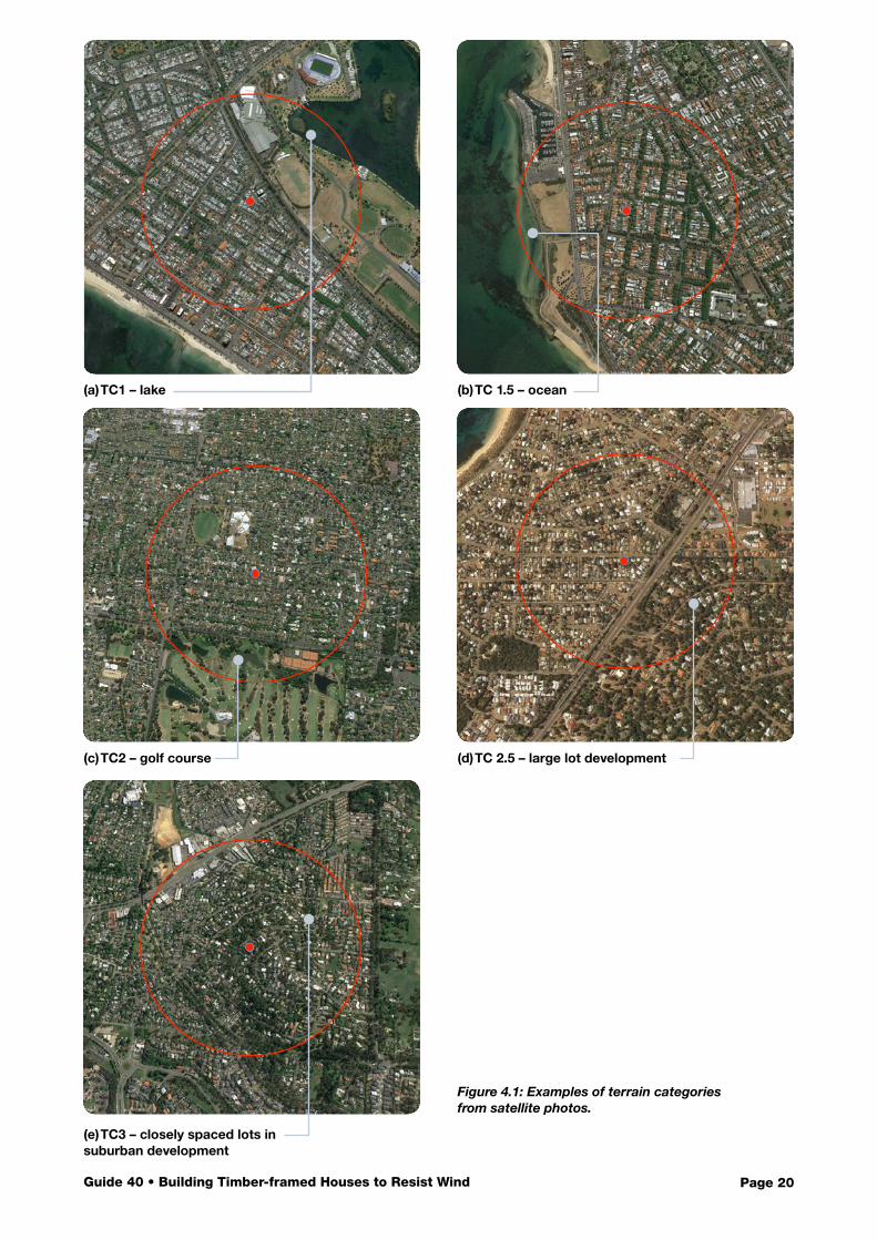
To assess the terrain category for a site, look at a satellite view of the suburb and overlay a 500 m radius circle centred on the house. This circle will have a diameter of 1 km on the ground (check with the scale on the satellite image). Examine the character of the most open section of land (at least 200 m wide) within the circle. Part of its width can extend outside of the circle, as shown in Figure 4.1(a), Figure 4.1(b) and Figure 4.1(c). This will indicate the TC for the site.
If the circle contains:
• any open water in lakes, canals, rivers, inlets, or small bays, then the terrain category is TC1. For this category, the water should extend for more than 200 m and less than 10 km, see Figure 4.1(a).
• any ocean, large harbour or a large bay, then the terrain category is TC1.5. For this category, the water should extend away from the house site by more than 10 km, see Figure 4.1(b).
• any open country typical of paddocks, ovals, playing fields, golf courses, cleared sub-divisions, then the terrain category is TC2. For this category, the open area should be wider than 200 m and have an area of roughly a quarter the size of the circle, see Figure 4.1(c).
• any large lot developments with fewer than 10 houses per hectare, then the terrain category is TC 2.5, see Figure 4.1(d).
• only suburban development with allotment sizes less than 1000 m2 that may also contain small parks, lakes, canals or road reserves (each less than 200 m wide), then the terrain category is TC3, see Figure 4.1(e). It is possible to include heavily wooded areas as TC3 in Wind Regions A and B only. (In Wind Regions C and D, heavily wooded areas should be considered as TC2).
The TC is based on the likely terrain in 5 years’ time, which allows for reasonable urban development early in the life of the house.
Page 20Guide 40 • Building Timber-framed Houses to Resist Wind
(a) TC1 – lake
(c) TC2 – golf course
(e) TC3 – closely spaced lots in suburban development
Figure 4.1: Examples of terrain categories from satellite photos.
(b) TC 1.5 – ocean
(d) TC 2.5 – large lot development
Page 21Guide 40 • Building Timber-framed Houses to Resist Wind
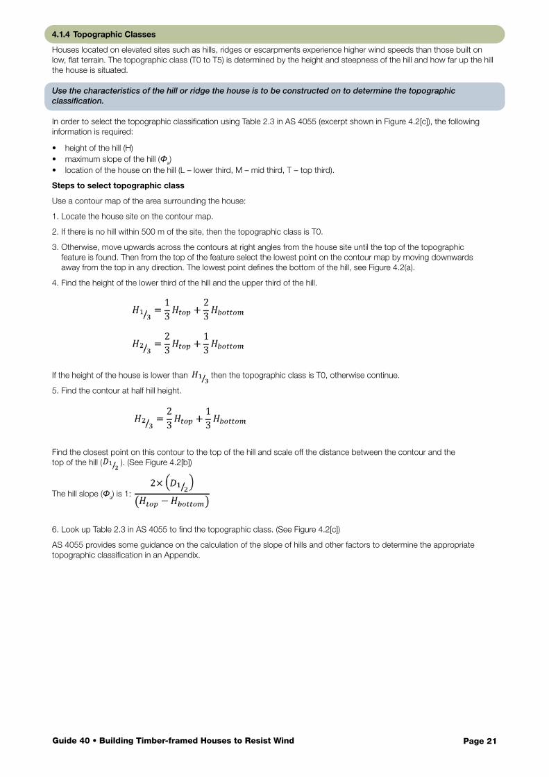
4.1.4 Topographic Classes
Houses located on elevated sites such as hills, ridges or escarpments experience higher wind speeds than those built on low, flat terrain. The topographic class (T0 to T5) is determined by the height and steepness of the hill and how far up the hill the house is situated.
Use the characteristics of the hill or ridge the house is to be constructed on to determine the topographic classification.
In order to select the topographic classification using Table 2.3 in AS 4055 (excerpt shown in Figure 4.2[c]), the following information is required:
• height of the hill (H)• maximum slope of the hill (Φa)• location of the house on the hill (L – lower third, M – mid third, T – top third).
Steps to select topographic class
Use a contour map of the area surrounding the house:
1. Locate the house site on the contour map.
2. If there is no hill within 500 m of the site, then the topographic class is T0.
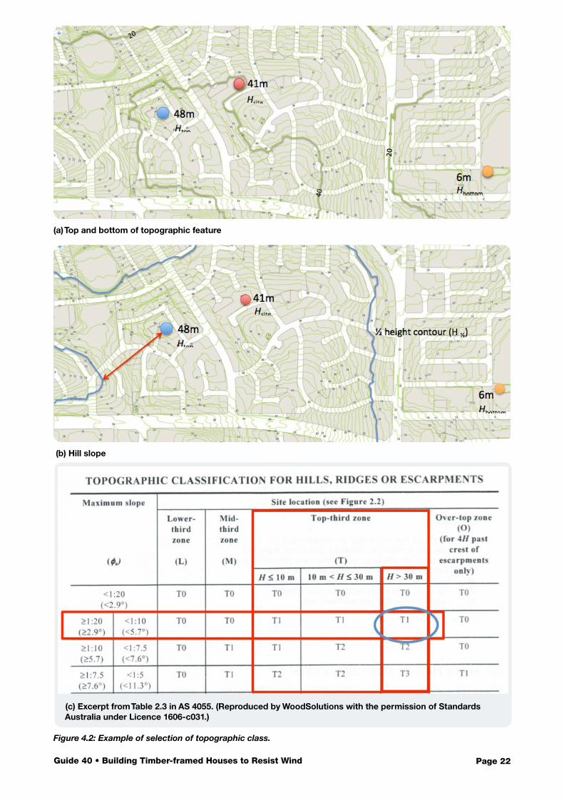
3. Otherwise, move upwards across the contours at right angles from the house site until the top of the topographic feature is found. Then from the top of the feature select the lowest point on the contour map by moving downwards away from the top in any direction. The lowest point defines the bottom of the hill, see Figure 4.2(a).
4. Find the height of the lower third of the hill and the upper third of the hill.
If the height of the house is lower than , then the topographic class is T0, otherwise continue.
5. Find the contour at half hill height.
Find the closest point on this contour to the top of the hill and scale off the distance between the contour and the top of the hill ( ). (See Figure 4.2[b]) The hill slope (Φa) is 1:
6. Look up Table 2.3 in AS 4055 to find the topographic class. (See Figure 4.2[c])
AS 4055 provides some guidance on the calculation of the slope of hills and other factors to determine the appropriate topographic classification in an Appendix.
Page 22Guide 40 • Building Timber-framed Houses to Resist Wind
(a) Top and bottom of topographic feature
(b) Hill slope
(c) Excerpt from Table 2.3 in AS 4055. (Reproduced by WoodSolutions with the permission of Standards Australia under Licence 1606-c031.)
Figure 4.2: Example of selection of topographic class.
Page 23Guide 40 • Building Timber-framed Houses to Resist Wind
Figure 4.2 illustrates an example using the steps above:
Steps 1 to 3:
The house is on a hill and the contour map indicates that
Htop = 48 m, Hbottom = 6 m, and the house site is at 41 m. (Figure 4.2[a])
The hill height (H) = 42 m.
Step 4:
H2/3 = 34 m, H1/3 = 20 m, so the house is in the top third of the hill.
Step 5:
Half height contour is 27 m and is marked in Figure 4.2(b).
The shortest distance between the H1/2 contour and the top of the hill is shown by the red arrow and scales to 280 m.
The slope of the hill = 21:280 = 1:13.
Step 6:
Table 2.3 in AS 4055 gives terrain classification T1, as shown in Figure 4.2(c).
Although the steps indicated above can be undertaken as a desk-top evaluation, the site should be visited to confirm the decisions made and conduct a rough check on whether the topographic classification for houses in suburban areas is appropriate.
It is recommended that an engineer is involved in all aspects of the structural design of houses on T5 sites.
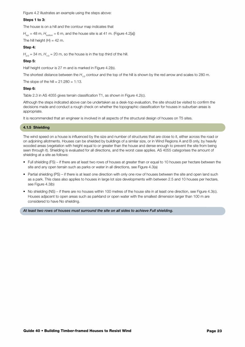
4.1.5 Shielding
The wind speed on a house is influenced by the size and number of structures that are close to it, either across the road or on adjoining allotments. Houses can be shielded by buildings of a similar size, or in Wind Regions A and B only, by heavily wooded areas (vegetation with height equal to or greater than the house and dense enough to prevent the site from being seen through it). Shielding is evaluated for all directions, and the worst case applies. AS 4055 categorises the amount of shielding at a site as follows:
• Full shielding (FS) – if there are at least two rows of houses at greater than or equal to 10 houses per hectare between the site and any open terrain such as parks or water in all directions, see Figure 4.3(a)
• Partial shielding (PS) – if there is at least one direction with only one row of houses between the site and open land such as a park. This class also applies to houses in large lot size developments with between 2.5 and 10 houses per hectare, see Figure 4.3(b)
• No shielding (NS) – if there are no houses within 100 metres of the house site in at least one direction, see Figure 4.3(c). Houses adjacent to open areas such as parkland or open water with the smallest dimension larger than 100 m are considered to have No shielding.
At least two rows of houses must surround the site on all sides to achieve Full shielding.
Page 24Guide 40 • Building Timber-framed Houses to Resist Wind
(a) Full shielding
(b) Partial shielding
(c) No shielding
Figure 4.3: Examples of selection of shielding class.
If, in any direction, there are no houses next to the site, then the site has No shielding.
Page 25Guide 40 • Building Timber-framed Houses to Resist Wind
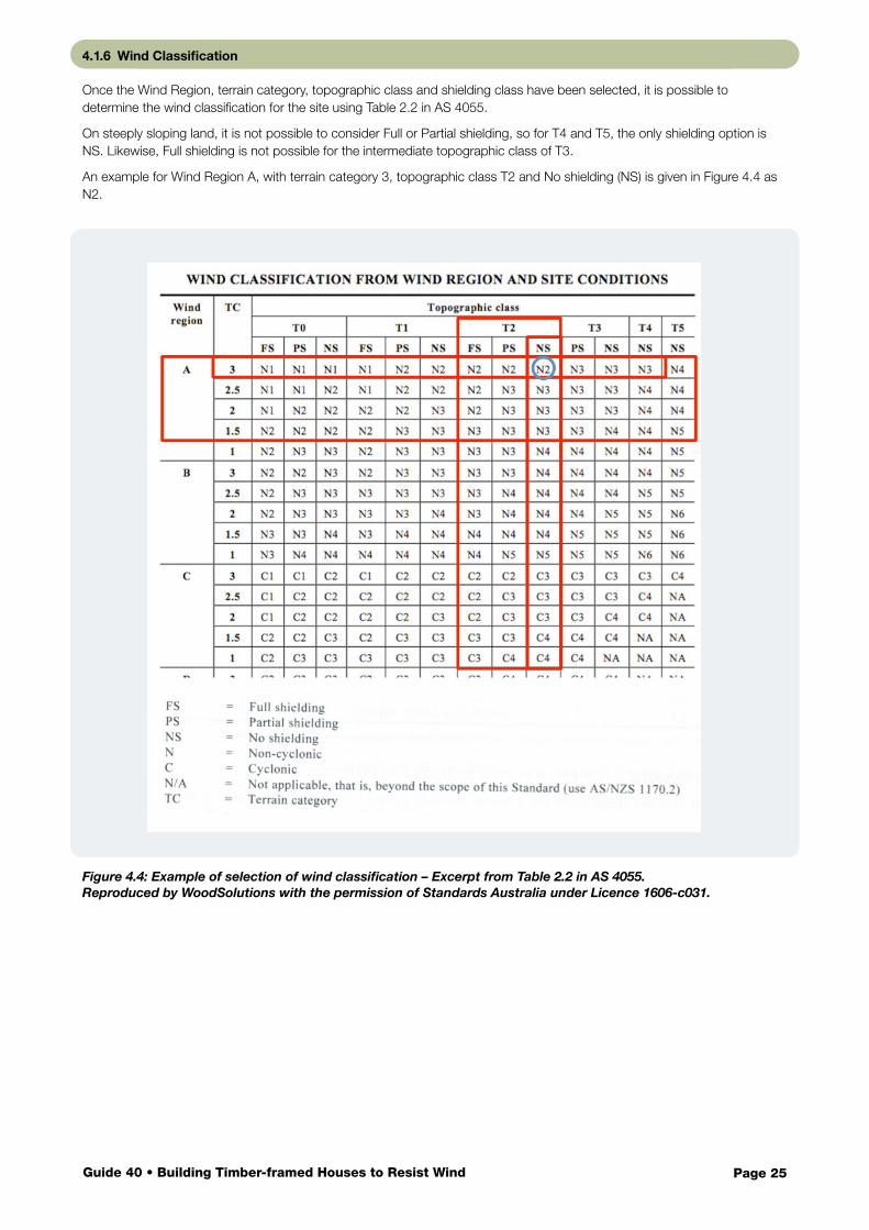
4.1.6 Wind Classification
Once the Wind Region, terrain category, topographic class and shielding class have been selected, it is possible to determine the wind classification for the site using Table 2.2 in AS 4055.
On steeply sloping land, it is not possible to consider Full or Partial shielding, so for T4 and T5, the only shielding option is NS. Likewise, Full shielding is not possible for the intermediate topographic class of T3.
An example for Wind Region A, with terrain category 3, topographic class T2 and No shielding (NS) is given in Figure 4.4 as N2.
Figure 4.4: Example of selection of wind classification – Excerpt from Table 2.2 in AS 4055. Reproduced by WoodSolutions with the permission of Standards Australia under Licence 1606-c031.
Page 26Guide 40 • Building Timber-framed Houses to Resist Wind
4.1.7 View Check of Wind Classification
More exposed sites have higher wind classifications. This includes homes close to the ocean or other open areas, high on hills or facing open areas such as parks. These houses usually enjoy good views. The view from the site can be used as a useful rough check on whether the wind classification specified on the plans for the house is likely to be correct:
• House has no view – generally N1 or C1
• House has a view past two rows of houses – generally N2 or C2
• House has a view over two suburban street blocks – usually N3 or C3
• House has a view beyond the suburb or out to sea – often N4 or higher, or C4 – an engineer should design all structural elements.
Houses with a great view generally have a high wind classification.
4.2 AS/NZS 1170.2
Where wind actions on a house are calculated using AS/NZS1170.2, engineers have to undertake a more detailed study to determine wind speeds and the pressures on building elements:
• The Wind Region for the site and a VR, regional design wind velocity is selected.
• Terrain category, topography and shielding are evaluated as velocity multipliers independently for eight cardinal wind directions centred on the site.
• These multipliers are used to determine eight directional design wind velocities.
• Appropriate design velocities are calculated for the face orientations of the house.
• The roof shape and wall configurations are used to evaluate pressure coefficients.
• Pressures on each external surface are calculated using the design wind velocity for the orientation and the appropriate pressure coefficient for the surface.
Page 27Guide 40 • Building Timber-framed Houses to Resist Wind
Contents
As discussed in Section 3.3, wind exerts significant uplift forces on a roof. Working to resist the wind uplift is the weight of the roof and the strength of all of the connections in the roof. For tiled roofs, the weight of the relatively heavy tiles helps to counteract the uplift forces. However, for lightweight roofs, the weight of the thin sheeting on its own is only just enough to resist the uplift created by a breeze, and high winds must be resisted by stronger connections within the roof system.
A continuous chain of tie-down details between the roofing and the ground is required for almost all wind classifications
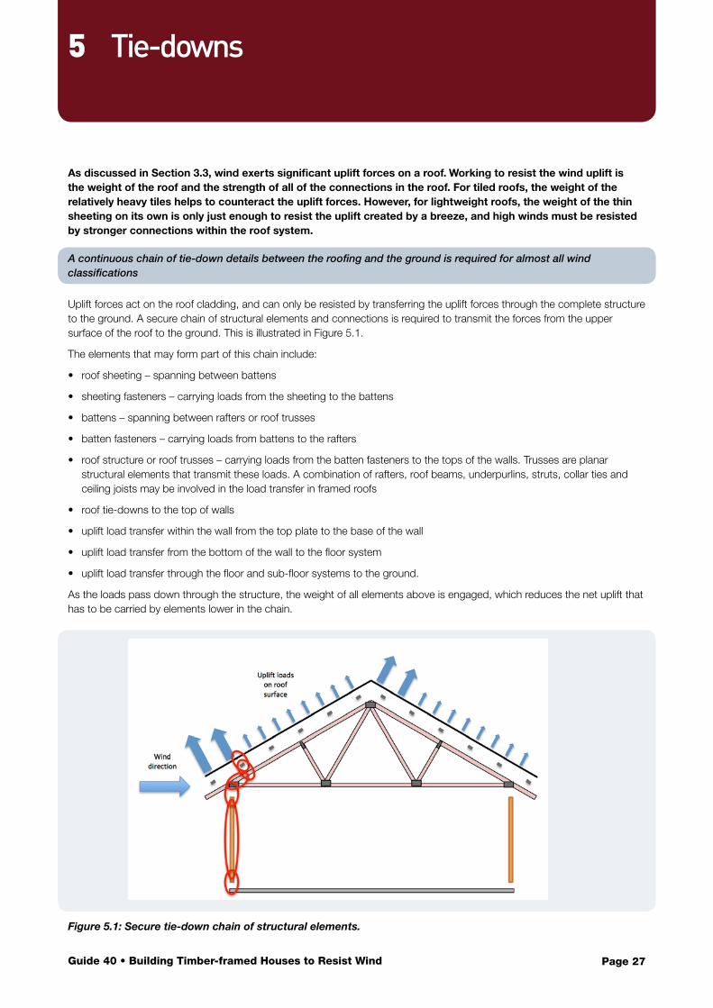
Uplift forces act on the roof cladding, and can only be resisted by transferring the uplift forces through the complete structure to the ground. A secure chain of structural elements and connections is required to transmit the forces from the upper surface of the roof to the ground. This is illustrated in Figure 5.1.
The elements that may form part of this chain include:
• roof sheeting – spanning between battens
• sheeting fasteners – carrying loads from the sheeting to the battens
• battens – spanning between rafters or roof trusses
• batten fasteners – carrying loads from battens to the rafters
• roof structure or roof trusses – carrying loads from the batten fasteners to the tops of the walls. Trusses are planar structural elements that transmit these loads. A combination of rafters, roof beams, underpurlins, struts, collar ties and ceiling joists may be involved in the load transfer in framed roofs
• roof tie-downs to the top of walls
• uplift load transfer within the wall from the top plate to the base of the wall
• uplift load transfer from the bottom of the wall to the floor system
• uplift load transfer through the floor and sub-floor systems to the ground.
As the loads pass down through the structure, the weight of all elements above is engaged, which reduces the net uplift that has to be carried by elements lower in the chain.
Figure 5.1: Secure tie-down chain of structural elements.
5 Tie-downs
Page 28Guide 40 • Building Timber-framed Houses to Resist Wind
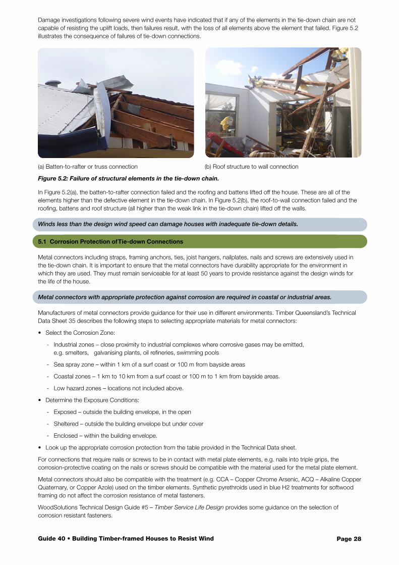
Damage investigations following severe wind events have indicated that if any of the elements in the tie-down chain are not capable of resisting the uplift loads, then failures result, with the loss of all elements above the element that failed. Figure 5.2 illustrates the consequence of failures of tie-down connections.
(a) Batten-to-rafter or truss connection (b) Roof structure to wall connection
Figure 5.2: Failure of structural elements in the tie-down chain.
In Figure 5.2(a), the batten-to-rafter connection failed and the roofing and battens lifted off the house. These are all of the elements higher than the defective element in the tie-down chain. In Figure 5.2(b), the roof-to-wall connection failed and the roofing, battens and roof structure (all higher than the weak link in the tie-down chain) lifted off the walls.
Winds less than the design wind speed can damage houses with inadequate tie-down details.
5.1 Corrosion Protection of Tie-down Connections
Metal connectors including straps, framing anchors, ties, joist hangers, nailplates, nails and screws are extensively used in the tie-down chain. It is important to ensure that the metal connectors have durability appropriate for the environment in which they are used. They must remain serviceable for at least 50 years to provide resistance against the design winds for the life of the house.
Metal connectors with appropriate protection against corrosion are required in coastal or industrial areas.
Manufacturers of metal connectors provide guidance for their use in different environments. Timber Queensland’s Technical Data Sheet 35 describes the following steps to selecting appropriate materials for metal connectors:
• Select the Corrosion Zone:
- Industrial zones – close proximity to industrial complexes where corrosive gases may be emitted, e.g. smelters, galvanising plants, oil refineries, swimming pools
- Sea spray zone – within 1 km of a surf coast or 100 m from bayside areas
- Coastal zones – 1 km to 10 km from a surf coast or 100 m to 1 km from bayside areas.
- Low hazard zones – locations not included above.
• Determine the Exposure Conditions:
- Exposed – outside the building envelope, in the open
- Sheltered – outside the building envelope but under cover
- Enclosed – within the building envelope.
• Look up the appropriate corrosion protection from the table provided in the Technical Data sheet.
For connections that require nails or screws to be in contact with metal plate elements, e.g. nails into triple grips, the corrosion-protective coating on the nails or screws should be compatible with the material used for the metal plate element.
Metal connectors should also be compatible with the treatment (e.g. CCA – Copper Chrome Arsenic, ACQ – Alkaline Copper Quaternary, or Copper Azole) used on the timber elements. Synthetic pyrethroids used in blue H2 treatments for softwood framing do not affect the corrosion resistance of metal fasteners.
WoodSolutions Technical Design Guide #5 – Timber Service Life Design provides some guidance on the selection of corrosion resistant fasteners.
Page 29Guide 40 • Building Timber-framed Houses to Resist Wind
5.2 General, Edge and Corner Areas of Roofs
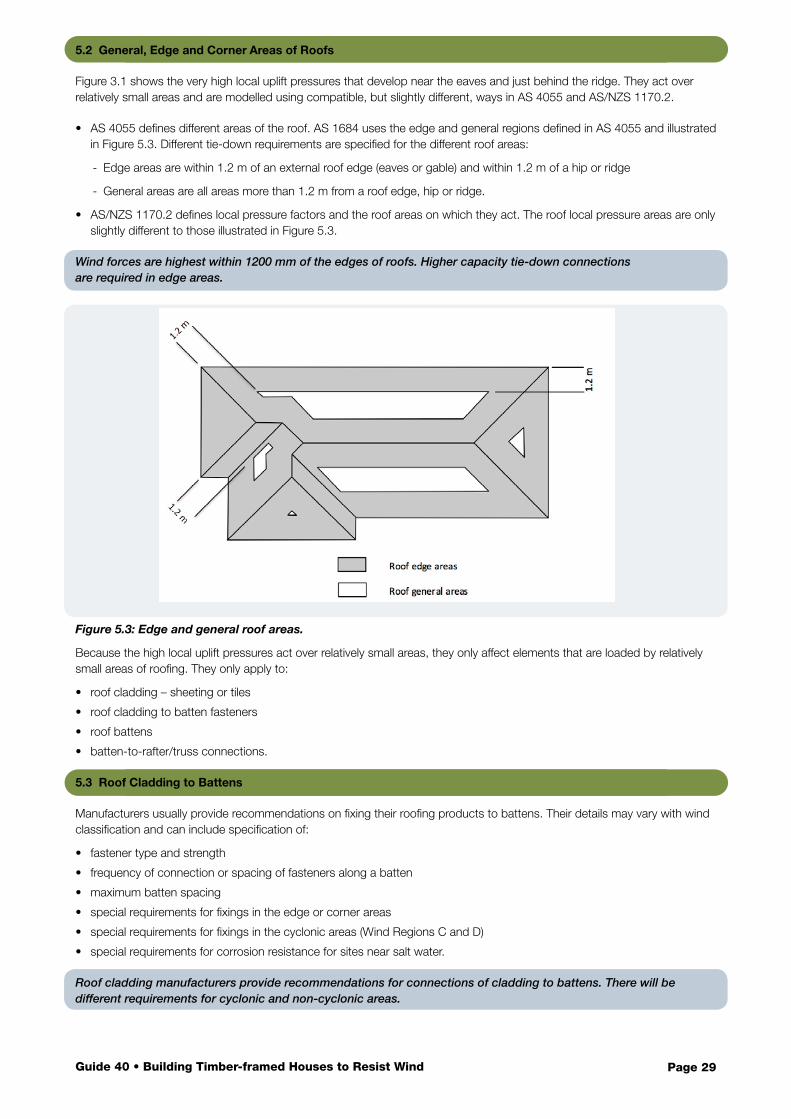
Figure 3.1 shows the very high local uplift pressures that develop near the eaves and just behind the ridge. They act over relatively small areas and are modelled using compatible, but slightly different, ways in AS 4055 and AS/NZS 1170.2.
• AS 4055 defines different areas of the roof. AS 1684 uses the edge and general regions defined in AS 4055 and illustrated in Figure 5.3. Different tie-down requirements are specified for the different roof areas:
- Edge areas are within 1.2 m of an external roof edge (eaves or gable) and within 1.2 m of a hip or ridge
- General areas are all areas more than 1.2 m from a roof edge, hip or ridge.
• AS/NZS 1170.2 defines local pressure factors and the roof areas on which they act. The roof local pressure areas are only slightly different to those illustrated in Figure 5.3.
Wind forces are highest within 1200 mm of the edges of roofs. Higher capacity tie-down connections are required in edge areas.
Figure 5.3: Edge and general roof areas.
Because the high local uplift pressures act over relatively small areas, they only affect elements that are loaded by relatively small areas of roofing. They only apply to:
• roof cladding – sheeting or tiles
• roof cladding to batten fasteners
• roof battens
• batten-to-rafter/truss connections.
5.3 Roof Cladding to Battens
Manufacturers usually provide recommendations on fixing their roofing products to battens. Their details may vary with wind classification and can include specification of:
• fastener type and strength
• frequency of connection or spacing of fasteners along a batten
• maximum batten spacing
• special requirements for fixings in the edge or corner areas
• special requirements for fixings in the cyclonic areas (Wind Regions C and D)
• special requirements for corrosion resistance for sites near salt water.
Roof cladding manufacturers provide recommendations for connections of cladding to battens. There will be different requirements for cyclonic and non-cyclonic areas.
Page 30Guide 40 • Building Timber-framed Houses to Resist Wind
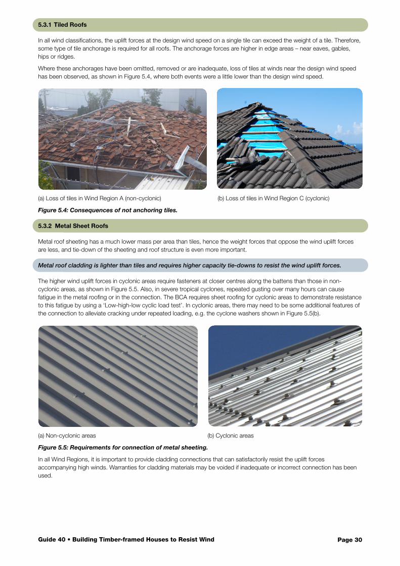
5.3.1 Tiled Roofs
In all wind classifications, the uplift forces at the design wind speed on a single tile can exceed the weight of a tile. Therefore, some type of tile anchorage is required for all roofs. The anchorage forces are higher in edge areas – near eaves, gables, hips or ridges.
Where these anchorages have been omitted, removed or are inadequate, loss of tiles at winds near the design wind speed has been observed, as shown in Figure 5.4, where both events were a little lower than the design wind speed.
(a) Loss of tiles in Wind Region A (non-cyclonic) (b) Loss of tiles in Wind Region C (cyclonic)
Figure 5.4: Consequences of not anchoring tiles.
5.3.2 Metal Sheet Roofs
Metal roof sheeting has a much lower mass per area than tiles, hence the weight forces that oppose the wind uplift forces are less, and tie-down of the sheeting and roof structure is even more important.
Metal roof cladding is lighter than tiles and requires higher capacity tie-downs to resist the wind uplift forces.
The higher wind uplift forces in cyclonic areas require fasteners at closer centres along the battens than those in non-cyclonic areas, as shown in Figure 5.5. Also, in severe tropical cyclones, repeated gusting over many hours can cause fatigue in the metal roofing or in the connection. The BCA requires sheet roofing for cyclonic areas to demonstrate resistance to this fatigue by using a ‘Low-high-low cyclic load test’. In cyclonic areas, there may need to be some additional features of the connection to alleviate cracking under repeated loading, e.g. the cyclone washers shown in Figure 5.5(b).
(a) Non-cyclonic areas (b) Cyclonic areas
Figure 5.5: Requirements for connection of metal sheeting.
In all Wind Regions, it is important to provide cladding connections that can satisfactorily resist the uplift forces accompanying high winds. Warranties for cladding materials may be voided if inadequate or incorrect connection has been used.
Page 31Guide 40 • Building Timber-framed Houses to Resist Wind
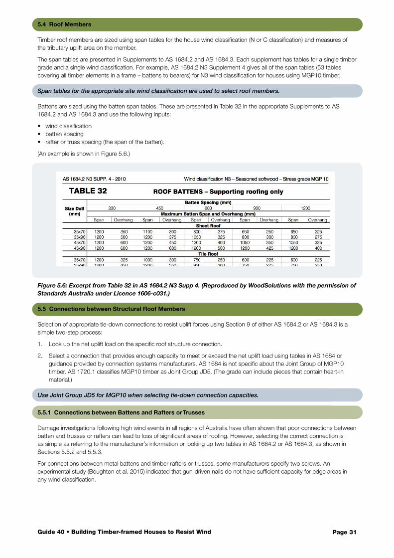
5.4 Roof Members
Timber roof members are sized using span tables for the house wind classification (N or C classification) and measures of the tributary uplift area on the member.
The span tables are presented in Supplements to AS 1684.2 and AS 1684.3. Each supplement has tables for a single timber grade and a single wind classification. For example, AS 1684.2 N3 Supplement 4 gives all of the span tables (53 tables covering all timber elements in a frame – battens to bearers) for N3 wind classification for houses using MGP10 timber.
Span tables for the appropriate site wind classification are used to select roof members.
Battens are sized using the batten span tables. These are presented in Table 32 in the appropriate Supplements to AS 1684.2 and AS 1684.3 and use the following inputs:
• wind classification• batten spacing• rafter or truss spacing (the span of the batten).
(An example is shown in Figure 5.6.)
Figure 5.6: Excerpt from Table 32 in AS 1684.2 N3 Supp 4. (Reproduced by WoodSolutions with the permission of Standards Australia under Licence 1606-c031.)
5.5 Connections between Structural Roof Members
Selection of appropriate tie-down connections to resist uplift forces using Section 9 of either AS 1684.2 or AS 1684.3 is a simple two-step process:
1. Look up the net uplift load on the specific roof structure connection.
2. Select a connection that provides enough capacity to meet or exceed the net uplift load using tables in AS 1684 or guidance provided by connection systems manufacturers. AS 1684 is not specific about the Joint Group of MGP10 timber. AS 1720.1 classifies MGP10 timber as Joint Group JD5. (The grade can include pieces that contain heart-in material.)
Use Joint Group JD5 for MGP10 when selecting tie-down connection capacities.
5.5.1 Connections between Battens and Rafters or Trusses
Damage investigations following high wind events in all regions of Australia have often shown that poor connections between batten and trusses or rafters can lead to loss of significant areas of roofing. However, selecting the correct connection is as simple as referring to the manufacturer’s information or looking up two tables in AS 1684.2 or AS 1684.3, as shown in Sections 5.5.2 and 5.5.3.
For connections between metal battens and timber rafters or trusses, some manufacturers specify two screws. An experimental study (Boughton et al, 2015) indicated that gun-driven nails do not have sufficient capacity for edge areas in any wind classification.
Page 32Guide 40 • Building Timber-framed Houses to Resist Wind
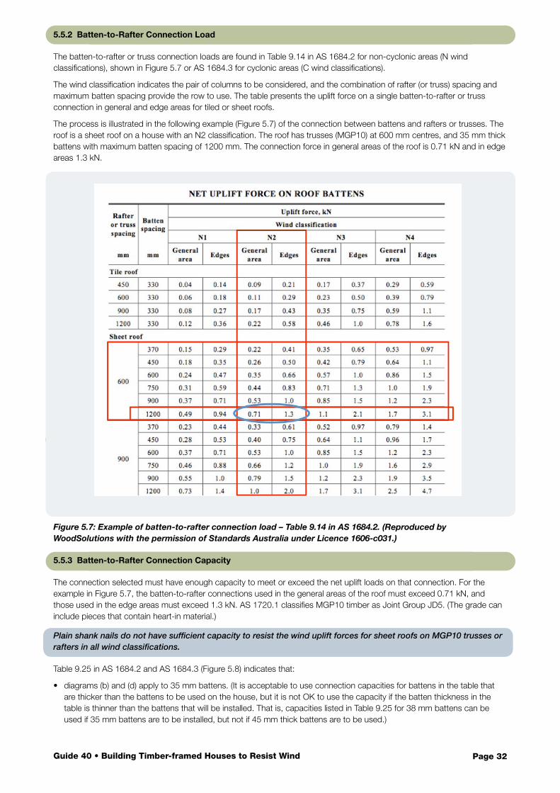
5.5.2 Batten-to-Rafter Connection Load
The batten-to-rafter or truss connection loads are found in Table 9.14 in AS 1684.2 for non-cyclonic areas (N wind classifications), shown in Figure 5.7 or AS 1684.3 for cyclonic areas (C wind classifications).
The wind classification indicates the pair of columns to be considered, and the combination of rafter (or truss) spacing and maximum batten spacing provide the row to use. The table presents the uplift force on a single batten-to-rafter or truss connection in general and edge areas for tiled or sheet roofs.
The process is illustrated in the following example (Figure 5.7) of the connection between battens and rafters or trusses. The roof is a sheet roof on a house with an N2 classification. The roof has trusses (MGP10) at 600 mm centres, and 35 mm thick battens with maximum batten spacing of 1200 mm. The connection force in general areas of the roof is 0.71 kN and in edge areas 1.3 kN.
Figure 5.7: Example of batten-to-rafter connection load – Table 9.14 in AS 1684.2. (Reproduced by WoodSolutions with the permission of Standards Australia under Licence 1606-c031.)
5.5.3 Batten-to-Rafter Connection Capacity
The connection selected must have enough capacity to meet or exceed the net uplift loads on that connection. For the example in Figure 5.7, the batten-to-rafter connections used in the general areas of the roof must exceed 0.71 kN, and those used in the edge areas must exceed 1.3 kN. AS 1720.1 classifies MGP10 timber as Joint Group JD5. (The grade can include pieces that contain heart-in material.)
Plain shank nails do not have sufficient capacity to resist the wind uplift forces for sheet roofs on MGP10 trusses or rafters in all wind classifications.
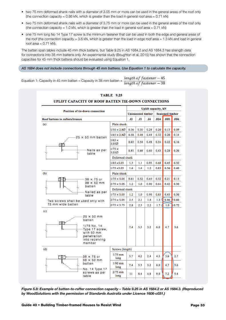
Table 9.25 in AS 1684.2 and AS 1684.3 (Figure 5.8) indicates that:
• diagrams (b) and (d) apply to 35 mm battens. (It is acceptable to use connection capacities for battens in the table that are thicker than the battens to be used on the house, but it is not OK to use the capacity if the batten thickness in the table is thinner than the battens that will be installed. That is, capacities listed in Table 9.25 for 38 mm battens can be used if 35 mm battens are to be installed, but not if 45 mm thick battens are to be used.)
Page 33Guide 40 • Building Timber-framed Houses to Resist Wind
• two 75 mm deformed shank nails with a diameter of 3.05 mm or more can be used in the general areas of the roof only (the connection capacity = 0.86 kN, which is greater than the load in general roof area = 0.71 kN)
• two 75 mm deformed shank nails with a diameter of 3.75 mm or more can be used in the general areas of the roof only (the connection capacity = 1.0 kN, which is greater than the load in general roof area = 0.71 kN)
• one 75 mm long No 14 Type 17 screw is the minimum fastener that can be used in both the edge and general areas of the roof (the connection capacity = 3.6 kN, which is greater than the load in edge roof area = 1.3 kN and load in general roof area = 0.71 kN).
The batten span tables include 45 mm thick battens, but Table 9.25 in AS 1684.2 and AS 1684.3 has strength data for connections into 38 mm battens only. An experimental study (Boughton et al, 2015) has shown that the connection capacities for 45 mm thick battens should be evaluated using Equation 1.
AS 1684 does not include connections through 45 mm battens. Use Equation 1 to calculate the capacity.
Equation 1: Capacity in 45 mm batten = Capacity in 38 mm batten ×
Figure 5.8: Example of batten-to-rafter connection capacity – Table 9.25 in AS 1684.2 or AS 1684.3. (Reproduced by WoodSolutions with the permission of Standards Australia under Licence 1606-c031.)
Page 34Guide 40 • Building Timber-framed Houses to Resist Wind
5.6 Tie-down through Roof Structure to Walls
Different tie-downs from the roof to the walls may be required, depending on the wall structure and material. In general, similar tie-downs can be used for houses with timber wall frames and cladding, and those with timber wall frames and brick veneer. AS 1684.2 and AS 1684.3 can be used for selecting tie-downs for both wall systems. However, houses with double brick walls or reinforced masonry require a connection from the timber roof structure to a masonry wall system which is not covered in AS 1684.2 and AS 1684.3.
5.6.1 Roof Trusses
Timber roof trusses are designed and manufactured (prefabricated off-site) to comply with AS 1720.5 and installed to comply with AS 4440. Trussed roof systems use the principle of triangulation to provide a rigid structural system that spans between the support points (usually the external walls). The trusses are loaded in uplift by the battens and transmit those loads to tie-downs at the support point. Trusses are designed using the wind classification for the house and design documentation provided by the manufacturer should outline the tie-down requirements at the support points.
Roof truss manufacturers provide information on tie-downs for trusses. Girder trusses require tie-downs with higher capacity.
Other tie-downs in the walls below the truss tie-downs must have the capacity to carry the uplift loads from the trusses.
If the tie-downs are not specified, then the uplift force in kN can be evaluated using Table 9.13 in AS 1684.2 or AS 1684.3. The Uplift Load Width (ULW) for a single tie-down point is half of the distance in plan between the tie-down points plus the width of any nearby overhang. A tie-down detail with the appropriate capacity can be selected using Table 9.21 in AS 1684.2 or AS 1684.3, and using the techniques outlined in Section 5.4.
Girder trusses
The wind uplift forces on girder trusses are significantly higher than those on standard trusses, due to the larger roof area supported by girder trusses. All girder trusses must have tie-downs with higher capacities than tie-downs for common trusses. All tie-downs through wall and floor systems below girder trusses must be sized for the higher uplift forces from the girder trusses.
Internal wall tie-down
In some situations, particularly in high wind locations, trusses may be designed to have tie- downs installed at intermediate support locations (i.e. not just at external walls, but at some internal walls as well). The capacity of tie-down required at these locations may be significantly higher than at the external wall tie-down points. The tie-down chain should transmit those forces all the way down to the foundations through the internal walls.
Internal support points will be marked on the truss and it is crucial to ensure that the internal walls line up with those points. If support for the truss is provided away from the marked location, the bottom chord of the truss may be damaged.
5.6.2 Stick-built Coupled Roofs
Elements for stick-built roofs, which include rafters, underpurlins, collar ties, struts and strutting beams, are assembled on-site. All members for stick-built roofs are sized using the appropriate span tables for the wind classification. There are some requirements that are different for coupled or non-coupled roofs. AS 1684 has definitions for these terms, but many houses seem to fall between the two categories. The explanatory material below helps identify the principle behind the classification.
Coupled roofs are defined in Clause 7.1.2.2 of AS 1684.2 and AS 1684.3.
“The roof pitch in a coupled roof construction shall be not less than 10o and ceiling joists and collar ties shall be fixed to opposing pairs of rafters, in accordance with Section 9.
Rafters shall be continuous in length from ridge to wall plate, or shall be lapped or spliced at their support points (see Clause 7.1.2.1). Rafters may be supported on underpurlins.”
The key point in the definition is that coupled roofs use triangulation to behave as pseudo trusses. The triangulation in the roof structure means that part of the roof uplift load can be carried using tension and compression in the roof members to the top of the external walls and tie-down connections can be similar to those for trussed roofs. Tie-downs for stick-built coupled roofs in wind classifications N1 and N2 can be evaluated using the AS 1684.2 tables for trusses (see Clause 9.6.3 in AS 1684.2).
Coupled roofs use collar ties and ceiling joists to achieve triangulation in the roof structure. Some special tie-down options can be used.
Page 35Guide 40 • Building Timber-framed Houses to Resist Wind
Some roofs may behave like coupled roofs although they do not meet the definition in Clause 7.1.2.2 of AS 1684.2 and AS 1684.3. For example, rafters at 900 mm spacings can only be tied to every second ceiling joist (at 600 mm spacings). While the definition uses the word “shall” for direct connection between rafters and ceiling joists, other references in the Standard indicate that it is possible to have some rafters that are not connected to ceiling joists within coupled roofs. The basic test of a coupled roof is that collar ties provide triangulation and there are good connections between rafters and ceiling joists where possible. So, if collar ties are installed on every pair of opposing rafters, the roof framing can still form a rigid structural system and may be considered to be a coupled roof. The tie-downs for coupled roofs can be used.
5.6.3 Stick-built Non-coupled Roofs
AS 1684 defines non-coupled roofs as:
“A non-coupled roof (including cathedral and skillion) shall have rafters (raking beams) supported off walls, ridge beams and/or intermediate beams. It may have ceilings in the same plane as the roof. Rafters, ridge and intermediate beams may be exposed internally.”
The ceiling configuration in some houses prevents the use of collar ties and ceiling joists in a separate plane to the rafters, making triangulation within the roof structure impossible. Although the roof system of coupled roofs can transfer the uplift forces through triangulation to the external walls, all individual elements in non-coupled roofs must have their own tie-down path to resist the uplift forces. For example, in roofs with cathedral ceilings, each connection between the rafters and the roof or intermediate beams must be selected using the appropriate tables in AS 1684 to resist the uplift forces. Each end of the roof and intermediate beams must also have appropriate tie-downs to transfer those forces through the walls to the ground. The process of selecting these connections is outlined in Section 5.5 and illustrated for batten connections.
Non-coupled roofs are typically in houses with cathedral ceilings, which prevent the use of triangulation in the roof structure. Each connection must be a tie-down connection.
5.6.4 Ribbon Plates
Ribbon plates can be nailed to the top of wall frame top plates. Tie-downs such as straps, triple grips or framing anchors should connect the truss or rafter to the top plate, not the ribbon plate. Connecting only to the ribbon plate will not provide load transfer to the wall.
5.7 Tie-down of Walls
For houses with tiled roofs and wind classifications of N3 and above, or sheet roofs and wind classifications of N2 and above, there is net wind uplift at the underside of the wall that requires continuation of the tie-down chain to the ground. The principles outlined in Section 5.5 can be extended to include the wall and floor systems.
Table 9.19 in AS 1684.2 and AS 1684.3 shows that tie-down forces can be carried through a timber wall frame using either connections between the studs and top and bottom plates or steel rods or plywood to carry uplift forces directly from the top plate to the bottom plate.
Plywood adjacent to openings cannot be used for tie-down at these locations, and other tie-down methods (see Table 9.20 in AS 1684.2 or AS 1684.3) are required. Plywood in structural bracing walls should not be used for tie-down.
5.7.1 Tie-down of Walls to Concrete Slab
Timber wall frames are tied-down to concrete slabs using either:
• hardened nails• cast-in bolts; or• chemical or other proprietary fasteners.
Tables 9.9 or 9.11 in AS 1684.2 and AS 1684.3 enable calculation of the tie-down forces required for connections between the walls and the slab and Table 9.18 in AS 1684.2 and AS 1684.3 provides capacities of connections.
5.7.2 Tie-down of Walls to Suspended Timber Floor Systems
Tie-down of walls to suspended timber floor systems requires the evaluation of forces and selection of connections for three positions in the floor system:
• walls to floor joists• floor joists to bearers• bearers to columns, posts or piers.
Appropriate connection details for all of these connections are presented in Clause 9 in AS 1684.2 and AS 1684.3. The connections of columns to their footings also have to transmit the net uplift force at the bottom of the floor system.
Page 36Guide 40 • Building Timber-framed Houses to Resist Wind
Contents
Bracing is required to enable the roof, wall and floor systems to resist net horizontal forces on the whole building from wind effects (See Section 3.4.) Appropriate materials and connections are required to transfer these forces through the timber frames to the foundations of the building.
Bracing is required to resist the net horizontal forces caused by wind on windward and leeward walls.
The magnitude of the total lateral wind force on the surface of a building depends on the wind classification, width of the building, the pitch of the roof and whether the house is single or two storeys. It will be different for winds parallel and perpendicular to the main ridge line.
6.1 Principles of Bracing in Houses
6.1.1 Bracing Load Paths
For design of bracing systems, two principle directions are considered:
• wind direction parallel to the larger dimension of the floor plan (generally parallel to the main ridge line in hip and gable roofs)
• wind direction perpendicular to the larger dimension of the floor plan.
Evaluate bracing and load capacity for wind in two directions.
For each of these wind directions, the net horizontal loads on the house are transferred to the ground as follows:
• Lateral loads caused by windward wall pressures put studs in the wall frames into bending. For upper storeys or single-storey houses, this transfers half of the load downward to the floor structure and half of it upward to the roof structure.
• The lateral loads in the roof structure are applied over the full length of the windward and leeward walls. The ceiling diaphragm (which structurally behaves as a plate or deep beam) transfers those loads to the top of walls that are parallel to the direction of the wind.
• The in-plane rigidity of the walls that are parallel to the wind transfers the horizontal forces in the ceiling diaphragm through the walls to the floor structure. Walls perpendicular to the wind direction are not counted as contributing to bracing in the house for that wind direction.
• On two-storey houses, the loads must then be added to the loads from the lower storey and transferred using bracing walls on the lower storey to the floor.
• Where the ground floor is a suspended floor, then the loads must be carried through the subfloor structure to the ground.
Figure 6.1 illustrates the load paths for one wind direction through two bracing walls in a single-storey house. It shows the critical role of the walls (both internal and external) in bracing the building against the horizontal forces generated by the wind.
6 Bracing Houses to Resist Lateral Forces
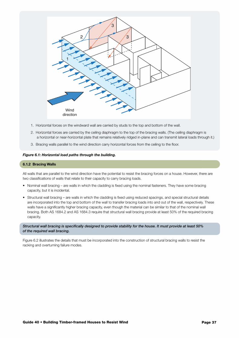
Page 37Guide 40 • Building Timber-framed Houses to Resist Wind
1. Horizontal forces on the windward wall are carried by studs to the top and bottom of the wall.
2. Horizontal forces are carried by the ceiling diaphragm to the top of the bracing walls. (The ceiling diaphragm is a horizontal or near-horizontal plate that remains relatively ridged in-plane and can transmit lateral loads through it.)
3. Bracing walls parallel to the wind direction carry horizontal forces from the ceiling to the floor.
Figure 6.1: Horizontal load paths through the building.
6.1.2 Bracing Walls
All walls that are parallel to the wind direction have the potential to resist the bracing forces on a house. However, there are two classifications of walls that relate to their capacity to carry bracing loads.
• Nominal wall bracing – are walls in which the cladding is fixed using the nominal fasteners. They have some bracing capacity, but it is incidental.
• Structural wall bracing – are walls in which the cladding is fixed using reduced spacings, and special structural details are incorporated into the top and bottom of the wall to transfer bracing loads into and out of the wall, respectively. These walls have a significantly higher bracing capacity, even though the material can be similar to that of the nominal wall bracing. Both AS 1684.2 and AS 1684.3 require that structural wall bracing provide at least 50% of the required bracing capacity.
Structural wall bracing is specifically designed to provide stability for the house. It must provide at least 50% of the required wall bracing.
Figure 6.2 illustrates the details that must be incorporated into the construction of structural bracing walls to resist the racking and overturning failure modes.
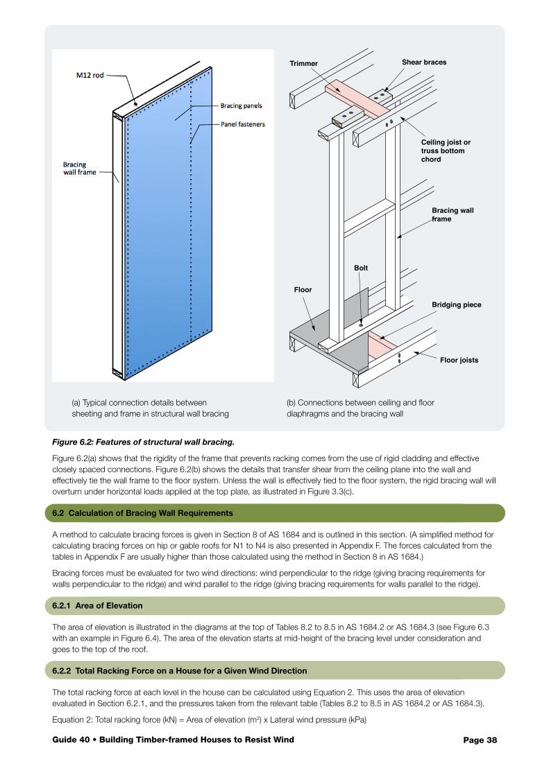
Page 38Guide 40 • Building Timber-framed Houses to Resist Wind
Figure 6.2: Features of structural wall bracing.
Figure 6.2(a) shows that the rigidity of the frame that prevents racking comes from the use of rigid cladding and effective closely spaced connections. Figure 6.2(b) shows the details that transfer shear from the ceiling plane into the wall and effectively tie the wall frame to the floor system. Unless the wall is effectively tied to the floor system, the rigid bracing wall will overturn under horizontal loads applied at the top plate, as illustrated in Figure 3.3(c).
6.2 Calculation of Bracing Wall Requirements
A method to calculate bracing forces is given in Section 8 of AS 1684 and is outlined in this section. (A simplified method for calculating bracing forces on hip or gable roofs for N1 to N4 is also presented in Appendix F. The forces calculated from the tables in Appendix F are usually higher than those calculated using the method in Section 8 in AS 1684.)
Bracing forces must be evaluated for two wind directions: wind perpendicular to the ridge (giving bracing requirements for walls perpendicular to the ridge) and wind parallel to the ridge (giving bracing requirements for walls parallel to the ridge).
6.2.1 Area of Elevation
The area of elevation is illustrated in the diagrams at the top of Tables 8.2 to 8.5 in AS 1684.2 or AS 1684.3 (see Figure 6.3 with an example in Figure 6.4). The area of the elevation starts at mid-height of the bracing level under consideration and goes to the top of the roof.
6.2.2 Total Racking Force on a House for a Given Wind Direction
The total racking force at each level in the house can be calculated using Equation 2. This uses the area of elevation evaluated in Section 6.2.1, and the pressures taken from the relevant table (Tables 8.2 to 8.5 in AS 1684.2 or AS 1684.3).
Equation 2: Total racking force (kN) = Area of elevation (m2) x Lateral wind pressure (kPa)
Floor joists
Bridging piece
Bolt
Floor
Bracing wall frame
Ceiling joist or truss bottom chord
Shear bracesTrimmer
(a) Typical connection details between sheeting and frame in structural wall bracing
(b) Connections between ceiling and floor diaphragms and the bracing wall
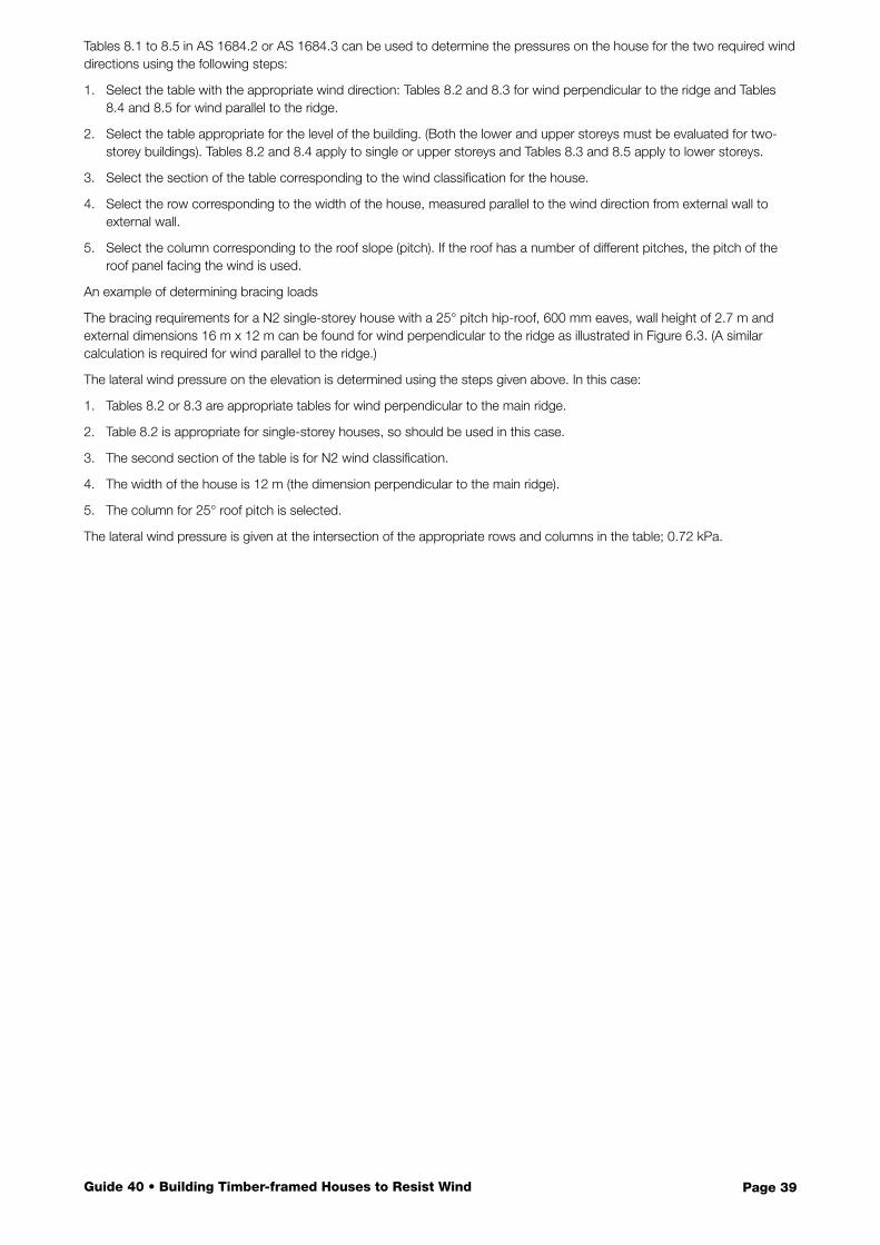
Page 39Guide 40 • Building Timber-framed Houses to Resist Wind
Tables 8.1 to 8.5 in AS 1684.2 or AS 1684.3 can be used to determine the pressures on the house for the two required wind directions using the following steps:
1. Select the table with the appropriate wind direction: Tables 8.2 and 8.3 for wind perpendicular to the ridge and Tables 8.4 and 8.5 for wind parallel to the ridge.
2. Select the table appropriate for the level of the building. (Both the lower and upper storeys must be evaluated for two-storey buildings). Tables 8.2 and 8.4 apply to single or upper storeys and Tables 8.3 and 8.5 apply to lower storeys.
3. Select the section of the table corresponding to the wind classification for the house.
4. Select the row corresponding to the width of the house, measured parallel to the wind direction from external wall to external wall.
5. Select the column corresponding to the roof slope (pitch). If the roof has a number of different pitches, the pitch of the roof panel facing the wind is used.
An example of determining bracing loads
The bracing requirements for a N2 single-storey house with a 25° pitch hip-roof, 600 mm eaves, wall height of 2.7 m and external dimensions 16 m x 12 m can be found for wind perpendicular to the ridge as illustrated in Figure 6.3. (A similar calculation is required for wind parallel to the ridge.)
The lateral wind pressure on the elevation is determined using the steps given above. In this case:
1. Tables 8.2 or 8.3 are appropriate tables for wind perpendicular to the main ridge.
2. Table 8.2 is appropriate for single-storey houses, so should be used in this case.
3. The second section of the table is for N2 wind classification.
4. The width of the house is 12 m (the dimension perpendicular to the main ridge).
5. The column for 25° roof pitch is selected.
The lateral wind pressure is given at the intersection of the appropriate rows and columns in the table; 0.72 kPa.
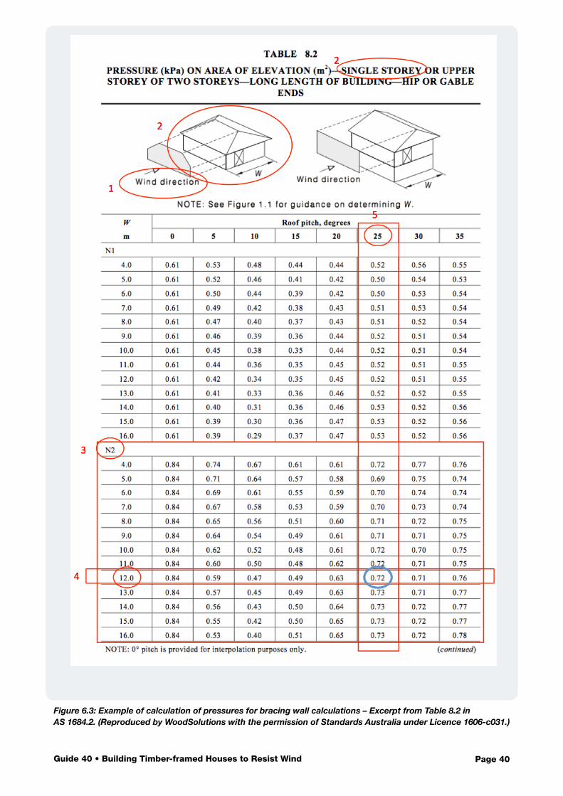
Page 40Guide 40 • Building Timber-framed Houses to Resist Wind
Figure 6.3: Example of calculation of pressures for bracing wall calculations – Excerpt from Table 8.2 in AS 1684.2. (Reproduced by WoodSolutions with the permission of Standards Australia under Licence 1606-c031.)
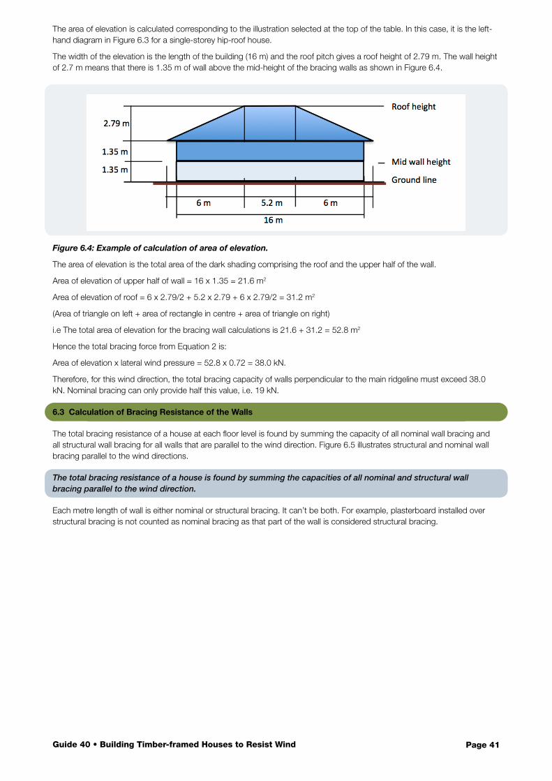
Page 41Guide 40 • Building Timber-framed Houses to Resist Wind
The area of elevation is calculated corresponding to the illustration selected at the top of the table. In this case, it is the left-hand diagram in Figure 6.3 for a single-storey hip-roof house.
The width of the elevation is the length of the building (16 m) and the roof pitch gives a roof height of 2.79 m. The wall height of 2.7 m means that there is 1.35 m of wall above the mid-height of the bracing walls as shown in Figure 6.4.
Figure 6.4: Example of calculation of area of elevation.
The area of elevation is the total area of the dark shading comprising the roof and the upper half of the wall.
Area of elevation of upper half of wall = 16 x 1.35 = 21.6 m2
Area of elevation of roof = 6 x 2.79/2 + 5.2 x 2.79 + 6 x 2.79/2 = 31.2 m2
(Area of triangle on left + area of rectangle in centre + area of triangle on right)
i.e The total area of elevation for the bracing wall calculations is 21.6 + 31.2 = 52.8 m2
Hence the total bracing force from Equation 2 is:
Area of elevation x lateral wind pressure = 52.8 x 0.72 = 38.0 kN.
Therefore, for this wind direction, the total bracing capacity of walls perpendicular to the main ridgeline must exceed 38.0 kN. Nominal bracing can only provide half this value, i.e. 19 kN.
6.3 Calculation of Bracing Resistance of the Walls
The total bracing resistance of a house at each floor level is found by summing the capacity of all nominal wall bracing and all structural wall bracing for all walls that are parallel to the wind direction. Figure 6.5 illustrates structural and nominal wall bracing parallel to the wind directions.
The total bracing resistance of a house is found by summing the capacities of all nominal and structural wall bracing parallel to the wind direction.
Each metre length of wall is either nominal or structural bracing. It can’t be both. For example, plasterboard installed over structural bracing is not counted as nominal bracing as that part of the wall is considered structural bracing.
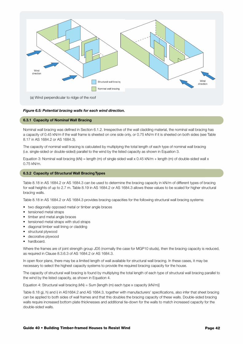
Page 42Guide 40 • Building Timber-framed Houses to Resist Wind
Figure 6.5: Potential bracing walls for each wind direction.
6.3.1 Capacity of Nominal Wall Bracing
Nominal wall bracing was defined in Section 6.1.2. Irrespective of the wall cladding material, the nominal wall bracing has a capacity of 0.45 kN/m if the wall frame is sheeted on one side only, or 0.75 kN/m if it is sheeted on both sides (see Table 8.17 in AS 1684.2 or AS 1684.3).
The capacity of nominal wall bracing is calculated by multiplying the total length of each type of nominal wall bracing (i.e. single-sided or double-sided) parallel to the wind by the listed capacity as shown in Equation 3.
Equation 3: Nominal wall bracing (kN) = length (m) of single sided wall x 0.45 kN/m + length (m) of double-sided wall x 0.75 kN/m.
6.3.2 Capacity of Structural Wall Bracing Types
Table 8.18 in AS 1684.2 or AS 1684.3 can be used to determine the bracing capacity in kN/m of different types of bracing for wall heights of up to 2.7 m. Table 8.19 in AS 1684.2 or AS 1684.3 allows these values to be scaled for higher structural bracing walls.
Table 8.18 in AS 1684.2 or AS 1684.3 provides bracing capacities for the following structural wall bracing systems:
• two diagonally opposed metal or timber angle braces• tensioned metal straps• timber and metal angle braces• tensioned metal straps with stud straps• diagonal timber wall lining or cladding• structural plywood• decorative plywood• hardboard.
Where the frames are of joint strength group JD5 (normally the case for MGP10 studs), then the bracing capacity is reduced, as required in Clause 8.3.6.3 of AS 1684.2 or AS 1684.3.
In open floor plans, there may be a limited length of wall available for structural wall bracing. In these cases, it may be necessary to select the highest capacity systems to provide the required bracing capacity for the house.
The capacity of structural wall bracing is found by multiplying the total length of each type of structural wall bracing parallel to the wind by the listed capacity, as shown in Equation 4.
Equation 4: Structural wall bracing (kN) = Sum [length (m) each type x capacity (kN/m)]
Table 8.18 g), h) and i) in AS1684.2 and AS 1684.3, together with manufacturers’ specifications, also infer that sheet bracing can be applied to both sides of wall frames and that this doubles the bracing capacity of these walls. Double-sided bracing walls require increased bottom plate thicknesses and additional tie-down for the walls to match increased capacity for the double-sided walls.
(a) Wind perpendicular to ridge of the roof
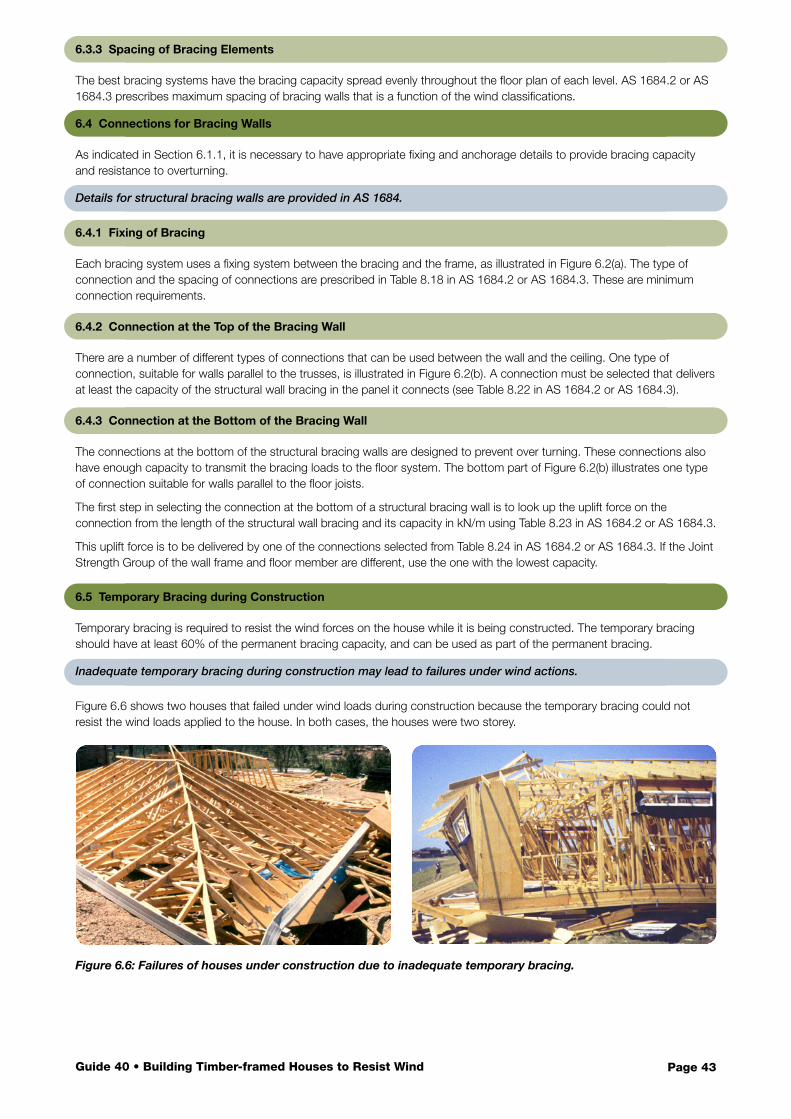
Page 43Guide 40 • Building Timber-framed Houses to Resist Wind
6.3.3 Spacing of Bracing Elements
The best bracing systems have the bracing capacity spread evenly throughout the floor plan of each level. AS 1684.2 or AS 1684.3 prescribes maximum spacing of bracing walls that is a function of the wind classifications.
6.4 Connections for Bracing Walls
As indicated in Section 6.1.1, it is necessary to have appropriate fixing and anchorage details to provide bracing capacity and resistance to overturning.
Details for structural bracing walls are provided in AS 1684.
6.4.1 Fixing of Bracing
Each bracing system uses a fixing system between the bracing and the frame, as illustrated in Figure 6.2(a). The type of connection and the spacing of connections are prescribed in Table 8.18 in AS 1684.2 or AS 1684.3. These are minimum connection requirements.
6.4.2 Connection at the Top of the Bracing Wall
There are a number of different types of connections that can be used between the wall and the ceiling. One type of connection, suitable for walls parallel to the trusses, is illustrated in Figure 6.2(b). A connection must be selected that delivers at least the capacity of the structural wall bracing in the panel it connects (see Table 8.22 in AS 1684.2 or AS 1684.3).
6.4.3 Connection at the Bottom of the Bracing Wall
The connections at the bottom of the structural bracing walls are designed to prevent over turning. These connections also have enough capacity to transmit the bracing loads to the floor system. The bottom part of Figure 6.2(b) illustrates one type of connection suitable for walls parallel to the floor joists.
The first step in selecting the connection at the bottom of a structural bracing wall is to look up the uplift force on the connection from the length of the structural wall bracing and its capacity in kN/m using Table 8.23 in AS 1684.2 or AS 1684.3.
This uplift force is to be delivered by one of the connections selected from Table 8.24 in AS 1684.2 or AS 1684.3. If the Joint Strength Group of the wall frame and floor member are different, use the one with the lowest capacity.
6.5 Temporary Bracing during Construction
Temporary bracing is required to resist the wind forces on the house while it is being constructed. The temporary bracing should have at least 60% of the permanent bracing capacity, and can be used as part of the permanent bracing.
Inadequate temporary bracing during construction may lead to failures under wind actions.
Figure 6.6 shows two houses that failed under wind loads during construction because the temporary bracing could not resist the wind loads applied to the house. In both cases, the houses were two storey.
Figure 6.6: Failures of houses under construction due to inadequate temporary bracing.
Page 44Guide 40 • Building Timber-framed Houses to Resist Wind
Contents
The Codes and Standards enable designers and builders to address all of the structural requirements that ensure new houses have the capacity to resist wind forces.
7.1 Compliance to BCA
The BCA specifies minimum requirements and assumes that all details will be designed and installed correctly. It makes no allowance for construction errors or omissions. A nation-wide study of houses under construction conducted by the CSIRO (Stewart, 2016) indicated that, in a survey of new houses under construction, almost all houses contained elements or connections that were incorrectly designed and/or installed. These included:
• incorrect wind classification for the site
• incorrect selection of fasteners for batten-to-rafter or truss connections (e.g. nails instead of screws used for batten-to-rafter or truss connections in edge regions of roofs)
• incorrectly installed connectors between trusses and top plates, or between rafters, underpurlins, struts and top plates
• insufficient tie-down in walls on either side of very large openings, or for beams in large outdoor areas under the main roof.
Houses will only perform well in high wind events if all details have been designed and installed correctly.
Damage investigations indicate that wind damage is more likely if there are errors in design or construction. Therefore, it is critical that designers and builders diligently apply the requirements of AS 4055 and AS 1684. If there is any doubt about a design or construction decision, then it is prudent to take a conservative approach.
7.2 Wind Classification
It is crucial that the wind classification for the house is correct. AS 4055 should be followed diligently and the classification checked using a site visit. If the classification is one level too low (e.g. classified as N1 when the site is actually N2), the wind loads on the tie-down connections will be almost double the value expected for the lower classification. This will lead to failure of connections and damage to the house in events with wind speeds lower than the design wind speed (see Section 4).
The correct wind classification for a house is vital to avoid failures in winds near the design wind event.
7.3 Timber Framing
Lightweight timber-framed houses are able to provide resistance to wind forces, provided that designers and builders correctly interpret and apply the tie-down requirements in AS 1684 (see Section 5).
Designers should specify details on the plans that enable tradespeople to install the correct tie-downs for each link in the tie-down chain. (Experience has shown that this approach is more effective than a standard note that refers to compliance with AS 1684.) Education in the industry and supervision during construction are required to focus on the importance of every single tie-down to the performance of the house under wind loads. Even small details matter, as any structural inadequacies have the potential to cause significant damage and compromise the safety of occupants.
Decisions about bracing are made at the design stage. Designating a wall as a structural bracing wall has implications for the adjoining roof and floor structure (see Section 6).
7.4 Internal Pressure
AS 1684.2 and AS 1684.3 span tables and connection loads incorporate assumptions on internal pressures consistent with AS 4055.
7 Construction of New Houses
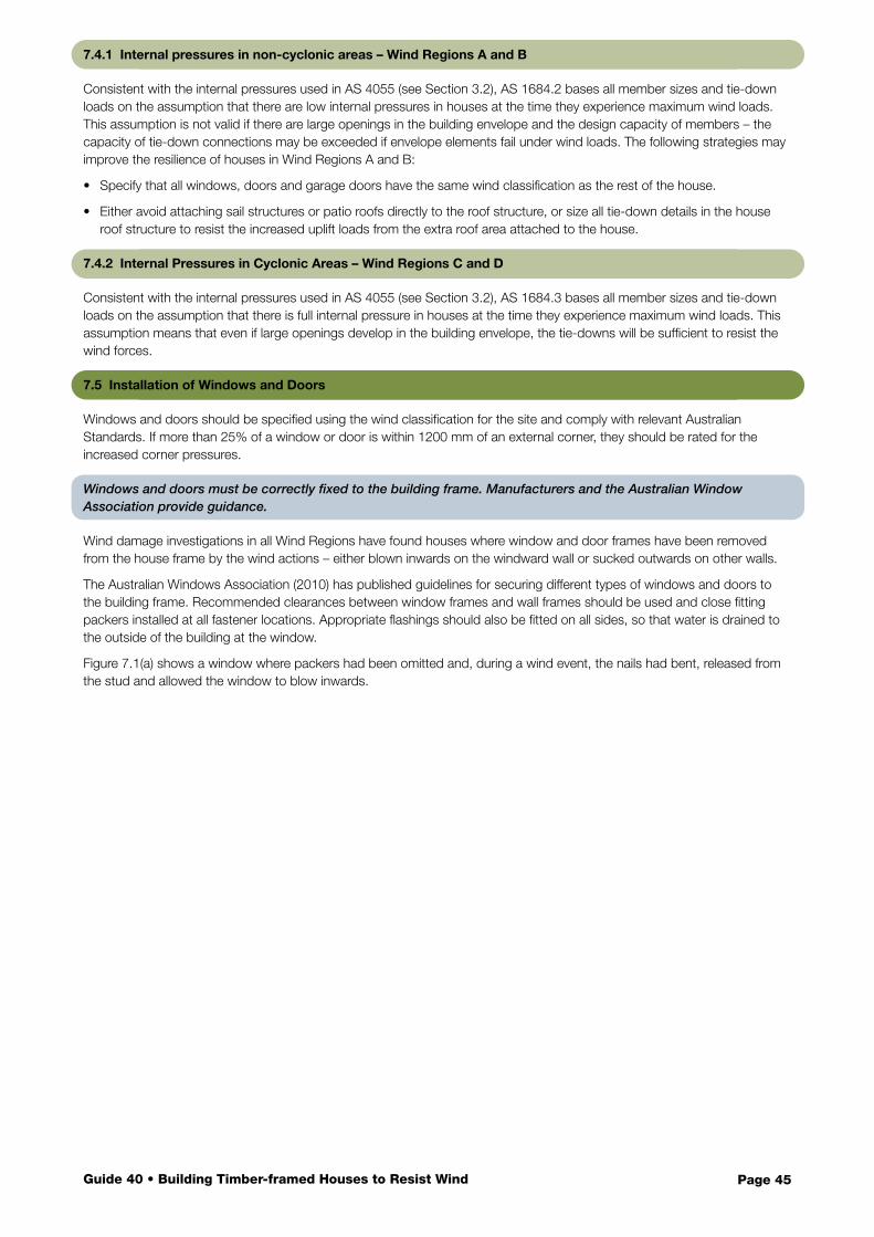
Page 45Guide 40 • Building Timber-framed Houses to Resist Wind
7.4.1 Internal pressures in non-cyclonic areas – Wind Regions A and B
Consistent with the internal pressures used in AS 4055 (see Section 3.2), AS 1684.2 bases all member sizes and tie-down loads on the assumption that there are low internal pressures in houses at the time they experience maximum wind loads. This assumption is not valid if there are large openings in the building envelope and the design capacity of members – the capacity of tie-down connections may be exceeded if envelope elements fail under wind loads. The following strategies may improve the resilience of houses in Wind Regions A and B:
• Specify that all windows, doors and garage doors have the same wind classification as the rest of the house.
• Either avoid attaching sail structures or patio roofs directly to the roof structure, or size all tie-down details in the house roof structure to resist the increased uplift loads from the extra roof area attached to the house.
7.4.2 Internal Pressures in Cyclonic Areas – Wind Regions C and D
Consistent with the internal pressures used in AS 4055 (see Section 3.2), AS 1684.3 bases all member sizes and tie-down loads on the assumption that there is full internal pressure in houses at the time they experience maximum wind loads. This assumption means that even if large openings develop in the building envelope, the tie-downs will be sufficient to resist the wind forces.
7.5 Installation of Windows and Doors
Windows and doors should be specified using the wind classification for the site and comply with relevant Australian Standards. If more than 25% of a window or door is within 1200 mm of an external corner, they should be rated for the increased corner pressures.
Windows and doors must be correctly fixed to the building frame. Manufacturers and the Australian Window Association provide guidance.
Wind damage investigations in all Wind Regions have found houses where window and door frames have been removed from the house frame by the wind actions – either blown inwards on the windward wall or sucked outwards on other walls.
The Australian Windows Association (2010) has published guidelines for securing different types of windows and doors to the building frame. Recommended clearances between window frames and wall frames should be used and close fitting packers installed at all fastener locations. Appropriate flashings should also be fitted on all sides, so that water is drained to the outside of the building at the window.
Figure 7.1(a) shows a window where packers had been omitted and, during a wind event, the nails had bent, released from the stud and allowed the window to blow inwards.
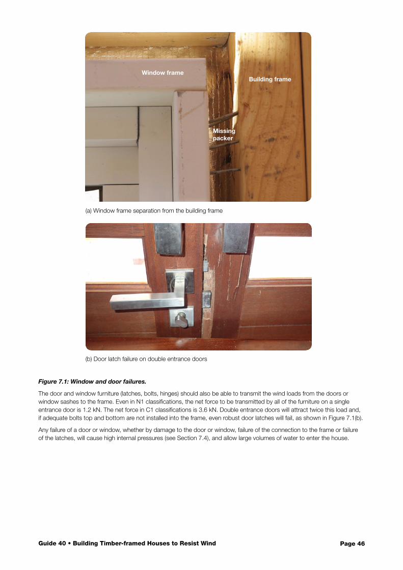
Page 46Guide 40 • Building Timber-framed Houses to Resist Wind
Figure 7.1: Window and door failures.
The door and window furniture (latches, bolts, hinges) should also be able to transmit the wind loads from the doors or window sashes to the frame. Even in N1 classifications, the net force to be transmitted by all of the furniture on a single entrance door is 1.2 kN. The net force in C1 classifications is 3.6 kN. Double entrance doors will attract twice this load and, if adequate bolts top and bottom are not installed into the frame, even robust door latches will fail, as shown in Figure 7.1(b).
Any failure of a door or window, whether by damage to the door or window, failure of the connection to the frame or failure of the latches, will cause high internal pressures (see Section 7.4), and allow large volumes of water to enter the house.
(a) Window frame separation from the building frame
(b) Door latch failure on double entrance doors
Building frameWindow frame
Missing packer
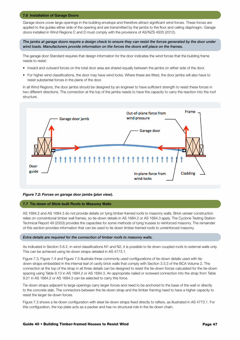
Page 47Guide 40 • Building Timber-framed Houses to Resist Wind
7.6 Installation of Garage Doors
Garage doors cover large openings in the building envelope and therefore attract significant wind forces. These forces are applied to the guides either side of the opening and are transmitted by the jambs to the floor and ceiling diaphragm. Garage doors installed in Wind Regions C and D must comply with the provisions of AS/NZS 4505 (2012).
The jambs at garage doors require a design check to ensure they can resist the forces generated by the door under wind loads. Manufacturers provide information on the forces the doors will place on the frames.
The garage door Standard requires that design information for the door indicates the wind forces that the building frame needs to resist:
• Inward and outward forces on the total door area are shared equally between the jambs on either side of the door.
• For higher wind classifications, the door may have wind locks. Where these are fitted, the door jambs will also have to resist substantial forces in the plane of the door.
In all Wind Regions, the door jambs should be designed by an engineer to have sufficient strength to resist these forces in two different directions. The connection at the top of the jambs needs to have the capacity to carry the reaction into the roof structure.
Figure 7.2: Forces on garage door jambs (plan view).
7.7 Tie-down of Stick-built Roofs to Masonry Walls
AS 1684.2 and AS 1684.3 do not provide details on tying timber-framed roofs to masonry walls. Brick veneer construction relies on conventional timber wall frames, so tie-down details in AS 1684.2 or AS 1684.3 apply. The Cyclone Testing Station Technical Report 49 (2003) provides the capacities for some methods of tying trusses to reinforced masonry. The remainder of this section provides information that can be used to tie down timber-framed roofs to unreinforced masonry.
Extra details are required for the connection of timber roofs to masonry walls.
As indicated in Section 5.6.2, in wind classifications N1 and N2, it is possible to tie down coupled roofs to external walls only. This can be achieved using tie-down straps detailed in AS 4773.1.
Figure 7.3, Figure 7.4 and Figure 7.5 illustrate three commonly used configurations of tie-down details used with tie-down straps embedded in the internal leaf of cavity brick walls that comply with Section 3.3.3 of the BCA Volume 2. The connection at the top of the strap in all three details can be designed to resist the tie-down forces calculated for the tie-down spacing using Table 9.13 in AS 1684.2 or AS 1684.3. An appropriate nailed or screwed connection into the strap from Table 9.21 in AS 1684.2 or AS 1684.3 can be selected to carry this force.
Tie-down straps adjacent to large openings carry larger forces and need to be anchored to the base of the wall or directly to the concrete slab. The connectors between the tie-down strap and the timber framing need to have a higher capacity to resist the larger tie-down forces.
Figure 7.3 shows a tie-down configuration with steel tie-down straps fixed directly to rafters, as illustrated in AS 4773.1. For this configuration, the top plate acts as a packer and has no structural role in the tie-down chain.
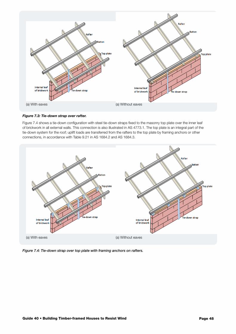
Page 48Guide 40 • Building Timber-framed Houses to Resist Wind
Figure 7.3: Tie-down strap over rafter.
Figure 7.4 shows a tie-down configuration with steel tie-down straps fixed to the masonry top plate over the inner leaf of brickwork in all external walls. This connection is also illustrated in AS 4773.1. The top plate is an integral part of the tie-down system for the roof; uplift loads are transferred from the rafters to the top plate by framing anchors or other connections, in accordance with Table 9.21 in AS 1684.2 and AS 1684.3.
Figure 7.4: Tie-down strap over top plate with framing anchors on rafters.
(a) With eaves
(a) With eaves
(a) Without eaves
(a) Without eaves
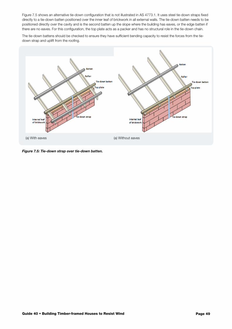
Page 49Guide 40 • Building Timber-framed Houses to Resist Wind
Figure 7.5 shows an alternative tie-down configuration that is not illustrated in AS 4773.1. It uses steel tie-down straps fixed directly to a tie-down batten positioned over the inner leaf of brickwork in all external walls. The tie-down batten needs to be positioned directly over the cavity and is the second batten up the slope where the building has eaves, or the edge batten if there are no eaves. For this configuration, the top plate acts as a packer and has no structural role in the tie-down chain.
The tie-down battens should be checked to ensure they have sufficient bending capacity to resist the forces from the tie-down strap and uplift from the roofing.
Figure 7.5: Tie-down strap over tie-down batten.
(a) With eaves (a) Without eaves
Page 50Guide 40 • Building Timber-framed Houses to Resist Wind
Contents
Investigations following high wind events in all regions of Australia have shown that many older buildings are damaged due to inadequacies in the tie-down system such as:
• deterioration of structural elements (e.g. corrosion of fasteners, rot or termites in timber elements)• weakening of connections during previous wind events• unauthorised additions• construction that would not meet the requirements of current Standards• damage from people walking on roofs.
Many structural tie-down connections can be difficult to access in completed houses. However, there are opportunities to check and improve the tie-downs when renovating, extending or repairing houses.
Where the roof structure was originally installed as unseasoned hardwood, it will have become seasoned over time and may split if screws are installed without pre-drilling. Seasoned hardwoods should be predrilled before installing all screws, including Type 17 screws. Care should also be used when nailing seasoned hardwoods to avoid splitting.
If existing timber members are split, or damaged by rot or insects, the member will be weakened and should be replaced.
8.1 Replacing Roof Cladding and Other Renovations
Replacement of roof cladding provides an ideal opportunity to check the structural connections between battens and rafters or trusses, and the roof structure to wall connections (see Sections 5.4 and 5.5). If Clause 9 of the current version of AS 1684 shows that the tie-down connections throughout the roof structure do not have the capacity to resist the wind loads for the site, then these connections should be upgraded to give the house sufficient strength to retain its new roofing in a design wind event.
When roof cladding is being replaced, take the opportunity to check and upgrade all tie-downs in the whole roof.
However, replacing a tiled roof with a sheet roof will require some upgrading to the roof tie-downs. The lighter mass of the sheet roofing dramatically increases the net uplift on the structure under wind actions, so the work has to include checks of the entire roof structure to ensure that each connection has the required tie-down capacity for the new cladding. The connections can often be strengthened using screws or straps once the tiles have been removed.
Other renovations that involve removal of at least part of the roof provide an opportunity to check and, if necessary, improve the tie-down chain in the roof structure. If problems are found in the part of the roof that has been inspected, it is advisable to make the same improvements to rest of the roof structure. This will mean that the renovated part of the house will not be endangered by failures in the original structure.
8.2 Additions and Extensions
Additions or extensions increase the size of a house and may mean that the completed house will not meet the geometric limitations in AS 4055 and AS 1684. If this is the case, then AS/NZS 1170:2 must be used to evaluate wind loads and AS 1720.1 used to design members and connections. Otherwise, AS 4055 and AS 1684 can be used as outlined in this Design Guide.
8.2.1 Check Wind Classification
If the wind classification is shown on plans for the existing house, then the wind classification for the site should also be checked (see Section 4) and revised if necessary. If the wind classification is not known, then it needs to be evaluated. Check if the new work requires a building permit. It is advisable that any new structural components comply with AS 1684.2 or AS 1684.3 for the correct wind classification. Although not mandatory, also check the tie-down capacity on the existing part of the house and upgrade if required to ensure the whole house can resist the design wind forces.
8 Tie-downs in Existing Houses
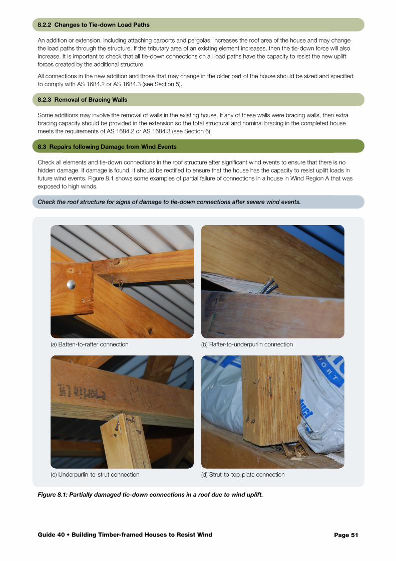
Page 51Guide 40 • Building Timber-framed Houses to Resist Wind
8.2.2 Changes to Tie-down Load Paths
An addition or extension, including attaching carports and pergolas, increases the roof area of the house and may change the load paths through the structure. If the tributary area of an existing element increases, then the tie-down force will also increase. It is important to check that all tie-down connections on all load paths have the capacity to resist the new uplift forces created by the additional structure.
All connections in the new addition and those that may change in the older part of the house should be sized and specified to comply with AS 1684.2 or AS 1684.3 (see Section 5).
8.2.3 Removal of Bracing Walls
Some additions may involve the removal of walls in the existing house. If any of these walls were bracing walls, then extra bracing capacity should be provided in the extension so the total structural and nominal bracing in the completed house meets the requirements of AS 1684.2 or AS 1684.3 (see Section 6).
8.3 Repairs following Damage from Wind Events
Check all elements and tie-down connections in the roof structure after significant wind events to ensure that there is no hidden damage. If damage is found, it should be rectified to ensure that the house has the capacity to resist uplift loads in future wind events. Figure 8.1 shows some examples of partial failure of connections in a house in Wind Region A that was exposed to high winds.
Check the roof structure for signs of damage to tie-down connections after severe wind events.
(a) Batten-to-rafter connection
(c) Underpurlin-to-strut connection
Figure 8.1: Partially damaged tie-down connections in a roof due to wind uplift.
(b) Rafter-to-underpurlin connection
(d) Strut-to-top-plate connection
Page 52Guide 40 • Building Timber-framed Houses to Resist Wind
Damage to part of a roof during a wind event is evidence of a structural deficiency, and it needs to be addressed anywhere it occurs in the whole roof, not just in the damaged section, as wind from a different direction may apply loads to connections that weren’t damaged in the original event.
If problems in the roof tie-downs are found in any part of the roof, check and upgrade all tie-downs throughout the roof.
Damage to a roof during a wind event could be caused by:
• a local structural deficiency such as a missing or poorly installed tie-down connection. In this case, the damage will be confined to a relatively small area. An inspection will show that other connections comply with AS 1684.2 or AS 1684.3 and do not need to be upgraded. Only the damaged portion of the roof needs to be repaired.
• a systematic weakness in a specific connection through the whole roof, e.g. batten-to-rafter connections with insufficient capacity. In this case, damage will be more widespread. All of the deficient connections, even those in parts of the roof that were not damaged, need to be upgraded to provide resilience for future wind events. It is also advisable to check the tie-down connections further into the structure to ensure they have the capacity to carry loads that will be successfully transferred to them by the upgraded connections. For example, if batten-to-rafter connections have failed, the connections below such as rafter-to-wall connections will not have been subjected to the full wind load during the event. Once the batten-to-rafter connections have been upgraded, then the full wind load can be transmitted to the rafter-to-wall connections in future events. If they haven’t been upgraded, they may now be ‘the weakest link’ in the chain and may fail.
• incorrect wind classification. In this case, other elements in the house such as windows and doors that may have been under-designed may also be damaged. This is particularly evident in houses on hills or in exposed locations where the original wind classification was taken as N1 or C1, but should have been higher. The wind classification should be checked (see Section 4) and the tie-down chain upgraded to match the new classification.
• deterioration of structural elements in the roof. In this case, the whole roof structure should be assessed and upgraded to meet the requirements of AS 1684.2 or AS 1684.3.
A number of useful references for repairing roofing after wind damage are available including:
• Planning for a stronger, more resilient North Queensland: Part 2 – Wind resistant housing – published by the Queensland Reconstruction Authority
• Tie-down details for repair of storm damaged roofs in south east Queensland – published on the Queensland Building and Construction Commission website: qbcc.qld.gov.au (appropriate for non-cyclonic areas)
• Repair of sheet metal roofs in cyclonic areas – published on the Queensland Building and Construction Commission website: qbcc.qld.gov.au (appropriate for cyclonic areas).
Page 53Guide 40 • Building Timber-framed Houses to Resist Wind
Contents
Australian Window Association (2010). Installation – An industry guide to the correct installation of windows and doors. Australian Window Association, Sydney, New South Wales.
Australian Window Association (2010). Fixing – An industry guide to the correct fixing of windows and doors. Australian Window Association, Sydney, New South Wales.
Australian Building Codes Board (2016). National Construction Code Series 2016 Volume Two – Building Code of Australia Class 1 and Class 10 Buildings. Australian Building Codes Board, Canberra.
Bureau of Meteorology. About tropical cyclones. Available from: http://www.bom.gov.au/cyclone/about/ [23 May 2016]
Boughton, GN (1999). Tropical Cyclone Vance – Damage to buildings in Exmouth. Department of Local Government, Western Australia.
Boughton, GN and Falck, DJ (2007). Tropical Cyclone George – Damage to buildings in the Port Hedland area, TR52. Cyclone Testing Station, James Cook University, Townsville.
Boughton, GN and Falck DJ (2008). Shoalwater and Roleystone WA tornadoes – wind damage to buildings, TR54. Cyclone Testing Station, James Cook University, Townsville.
Boughton GN, Henderson DJ, Ginger JD, Holmes JD, Walker GR, Leitch CJ, Somerville LR, Frye U, Jayasinghe NC, and Kim, PY (2011). Tropical Cyclone Yasi – Structural damage to buildings, TR57. Cyclone Testing Station, James Cook University, Townsville.
Boughton, GN and Falck DJ (2015). Tropical Cyclone Olwyn – Damage to buildings in Exmouth, Western Australia, TR61. Cyclone Testing Station, James Cook University, Townsville.
Boughton, GN, Falck, DJ, Duong, AVN, Pham, S, and Nguyen, A. (2015). Static testing of batten connections at University of Western Australia, TR62. Cyclone Testing Station, James Cook University, Townsville.
Duong, AVN (2015). Analysis of the Failure Behaviour of Screw Batten-to-Rafter Connections in Steel Clad Roof Structures, Thesis. University of Western Australia, Perth.
Henderson, DJ, and Leitch, C (2005). Damage investigation of buildings at Minjilang, Cape Don and Smith Point in NT following Cyclone Ingrid, TR50. Cyclone Testing Station, James Cook University, Townsville.
Henderson, DJ, Ginger, J, Leitch, C, Boughton, GN, and Falck, DJ (2006). Tropical Cyclone Larry – damage to buildings in the Innisfail area, TR51. Cyclone Testing Station, James Cook University, Townsville.
International Standards Organisation (2016) ISO 12122.5 Timber structures – determination of characteristic values Part 5 Mechanical connections. International Standards Organisation, Geneva, Switzerland.
Henderson, DJ, Ginger, J, Kim, P, and Sumant, B (2012). Investigation of Townsville tornado, 20 March 2012, TR58. Cyclone Testing Station, James Cook University, Townsville.
Leitch, C, Cummins, W, Henderson, D (2003). An investigation of bond beam truss hold down connections, TR49. Cyclone Testing Station, James Cook University, Townsville.
Leitch, C, Ginger, J, Harper, B, Kim, P, Jayasinghe, N, and Somerville, L (2009). Investigation of Performance of Housing in Brisbane following storms on 16 and 19 November 2008, TR55. Cyclone Testing Station, James Cook University, Townsville.
Lysaght (2014), Topspan design and installation guide for building professionals. Available from: <www.lysaght.com> [5 September, 2014].
Mahendran, M and Mahaarachchi, D (2002). Cyclic pull-out strength of screwed connections in steel roof and wall cladding systems using thin steel battens. Journal of Structural Engineering 10.1061 pp771-778.
Nguyen, A. (2015) Analysis of the Failure Behaviour of Screw Batten-to-Rafter Connections in Timber Roof Structures, Thesis. University of Western Australia, Perth.
Parackal, K, Mason, M, Henderson, D, Stark, G, Ginger, J, Somerville, L, Harper, B, Smith, D and Humphreys, M (2015). Investigation of Damage: Brisbane, 27 November 2014 severe storm event, TR60. Cyclone Testing Station, James Cook University, Townsville.
References
Page 54Guide 40 • Building Timber-framed Houses to Resist Wind
Pham, S (2015). Analysis of the Failure Behaviour of Nail Batten-to-Rafter Connections in Steel Clad Roof Structures, Thesis. University of Western Australia, Perth.
Prevatt, D, Shreyans, S, Kerr, A & Gurley, K. (2014). In Situ Nail Withdrawal Strengths in Wood Roof Structures. Journal of Structural Engineering, Vol. 140, No. 5, pp. 1-8.
Queensland Building and Construction Commission. Tie-down details for repair of storm damaged roofs in south east Queensland Available from: http://www.qbcc.qld.gov.au [20 June 2016].
Queensland Building and Construction Commission. Repair of sheet metal roofs in cyclonic areas Available from: http://www.qbcc.qld.gov.au [20 June 2016].
Queensland Reconstruction Authority (2011) Planning for a stronger, more resilient North Queensland Part 2 Wind resistant housing. Queensland Reconstruction Authority, Queensland Government. Brisbane, Queensland.
Reardon, G. F. (1979a). The strength of batten-to-rafter joints Part 1 – Test results and derivation of design loads, TR 2. Cyclone Testing Station, James Cook University, Townsville.
Reardon, GF (1979b) The strength of batten-to-rafter joints Part 2 – Recommendations for high wind areas, TR 3. Cyclone Testing Station, James Cook University, Townsville.
Reardon, GF, Henderson, DJ, and Ginger, J (1999). A structural assessment of the effects of Cyclone Vance on houses in Exmouth WA, TR48. Cyclone Testing Station, James Cook University, Townsville.
Stewart, M, Wang, X, Bradford, M, Ginger, J, Hao, H, Sanjayan, J, Willgoose, G, and Wilson, J (2016). Final Report – Climate adaptation engineering for extreme events cluster, CAEx Report 1/2016. CSIRO, Canberra, Australia, March 2016.
Timber Queensland (2015) Wind tie-down connections – Getting it right Technical Data Sheet 32. Timber Queensland Limited. Brisbane, Queensland.
Timber Queensland (2015) Corrosion resistance of metal connectors Technical Data Sheet 35. Timber Queensland Limited. Brisbane, Queensland.
Australian Standards
Standards Australia (2002). AS/NZS 1170.0:2002 Structural design actions Part 0: General principles. Standards Australia, Sydney, NSW, Australia.
Standards Australia (2011). AS/NZS 1170.2:2011 Structural design actions. Part 2: Wind actions. Standards Australia, Sydney, NSW, Australia.
Standards Australia (2001). AS 1649 Timber – Methods of test for mechanical fasteners and connectors – Basic working loads and characteristic strengths. Standards Australia, Sydney, NSW, Australia.
Standards Australia (2010a). AS 1684.2 Residential timber-framed housing, Part 2 Non-cyclonic areas. Standards Australia, Sydney, NSW, Australia.
Standards Australia (2010b). AS 1684.3 Residential timber-framed housing, Part 3 Cyclonic areas. Standards Australia, Sydney, NSW, Australia.
Standards Australia (2010c). AS 1684.2 N3 Supplement 4–2010 Residential timber-framed housing, Part 2 Non-cyclonic areas N3 Supplement 4: Timber framing span tables–Wind classification N3–Seasoned softwood–Stress Grade MGP 10 (Supplement to AS 1684.2–2010). Standards Australia, Sydney, NSW, Australia.
Standards Australia (2010d). AS 1720.1 Timber structures Part 1: Design methods. Standards Australia, Sydney, NSW, Australia.
Standards Australia (2015). AS 1720.5 Timber structures Part 5: Nailplated timber roof trusses. Standards Australia, Sydney, NSW, Australia.
Standards Australia (2012). AS 4055 Wind loads for housing. Standards Australia, Sydney, NSW, Australia.
Standards Australia (2010e). AS/NZS 4063.2 Characterization of structural timber Part 2: Determination of characteristic values. Standards Australia, Sydney, NSW, Australia.
Standards Australia (2005). AS 4357.0 Structural laminated veneer lumber Part 0: Specifications. Standards Australia, Sydney, NSW, Australia.
Standards Australia (2004). AS 4440 Installation of nailplated timber roof trusses. Standards Australia, Sydney, NSW, Australia.
Standards Australia (2012). AS/NZS 4505: Garage doors and other large access doors. Standards Australia, Sydney, NSW, Australia.
Standards Australia (2015). AS 4773.1 Masonry in small buildings Part 1: Design. Standards Australia, Sydney, NSW, Australia.
Page 55Guide 40 • Building Timber-framed Houses to Resist Wind
WoodSolutions Publications
The WoodSolutions website woodsolutions.com.au provides other User Guides and Technical Design Guides to support the use of AS 1684 and timber-framed construction:
WoodSolutions Technical Design Guide #1: Timber-framed construction for townhouse buildings Class 1a. Forest and Wood Products Australia, Melbourne, Australia, 2012.
WoodSolutions Technical Design Guide #5: Timber Service Life Design. Forest and Wood Products Australia, Melbourne, Australia
AS 1684 User Guide 1 – Nominal vs specific fixings. Forest and Wood Products Australia, Melbourne, Australia.
AS 1684 User Guide 2 – Temporary bracing. Forest and Wood Products Australia, Melbourne, Australia
AS 1684 User Guide 3 – Simplified tie-down details for coupled roofs. Forest and Wood Products Australia, Melbourne, Australia
AS 1684 User Guide 4 – External wall heights. Forest and Wood Products Australia, Melbourne, Australia
AS 1684 User Guide 5 – Fixing of top of bracing walls. Forest and Wood Products Australia, Melbourne, Australia
AS 1684 User Guide 6 – Roof truss tie-down. Forest and Wood Products Australia, Melbourne, Australia
AS 1684 User Guide 7 – Ridgeboard and hip rafter tie-down. Forest and Wood Products Australia, Melbourne, Australia
AS 1684 User Guide 8 – Masonry anchor tie-down. Forest and Wood Products Australia, Melbourne, Australia
AS 1684 User Guide 9 – Fixing of bottom of hardboard bracing walls. Forest and Wood Products Australia, Melbourne, Australia.
AS 1684 User Guide 10 – Distribution of racking forces via diaphragms. Forest and Wood Products Australia, Melbourne, Australia
Additional Resources
The Cyclone Testing Station website (www.cyclonetestingstation.com.au) provides information for builders, designers and home-owners on construction to resist wind loads. The resources include videos on:
• site wind classifications for houses
• a worked example to determine the wind classification for a house
• upgrading an older roof
• re-roofing after storm damage.

Page 56Guide 40 • Building Timber-framed Houses to Resist Wind
Discover more ways to build your knowledge of wood If you need technical information or inspiration on designing and building with wood, you’ll find WoodSolutions has the answers. From technical design and engineering advice to inspiring projects and CPD linked activities, WoodSolutions has a wide range of resources and professional seminars.
www.woodsolutions.com.auYour central resource for news about all WoodSolutions activities and access to more than three thousand pages of online information and downloadable publications.
Technical PublicationsA suite of informative, technical and training guides and handbooks that support the use of wood in residential and commercial buildings.
WoodSolutions TutorialsA range of practical and inspirational topics to educate and inform design and construction professionals. These free, CPD related, presentations can be delivered at your workplace at a time that suits you.
Seminars and EventsFrom one day seminars featuring presentations from leading international and Australian speakers to international tours of landmark wood projects, WoodSolutions offer a range of professional development activities.
What is WoodSolutions?Developed by the Australian forest and wood products industry for design and building professionals, WoodSolutions is a non-proprietary source of information from industry bodies, manufacturers and suppliers.