bulk electric system john d. martinsen, p.e. snohomish county public utility district (snpd)
TRANSCRIPT
Bulk Electric System
John D. Martinsen, P.E.Snohomish County Public Utility District (SNPD)
2
Summary
• Part 1• “Performance Based” Bulk Electric System
(“BES”) definition• BES definition(s)• NERC, WECC, and electric industry efforts in
defining the BES
• Part 2 • Examples of BPA Transmission and Distribution
systems
3
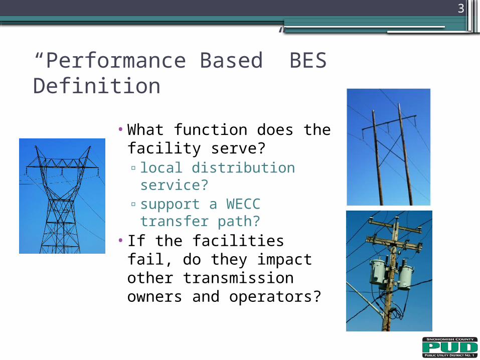
“Performance Based” BES Definition
• What function does the facility serve?▫ local distribution
service?▫support a WECC
transfer path?• If the facilities fail, do
they impact other transmission owners and operators?
4
• Western Interconnection development of a “performance based” standard▫ FERC support of WECC effort in Order 743-A
• BPA comments on the revision of the ERO definition of the BES (Docket No. RM09-18-000) ▫ “…Western Interconnection, utilities must use higher voltage facilities, i.e.,
115 kV, to accomplish what is effectively a distribution function with in the utility. Where demonstrated, these facilities should be categorized as distribution network components, not as bulk electric system facilities…”
▫ “… Bonneville urges the Commission to provide an additional option for the ERO to submit a Regional Entities material impact methodology for Commission approval…”
▫ “…Agrees with the need to exempt FAC that have low impact on the BES…”▫ “…Bonneville believes many facilities in the Western Interconnection rated
at 100kV and above should not be included in the BES because they have no material impact on the bulk power system reliability…”
Bulk Electric System Definition Task Force (“BESDTF”)
5
• NERC Bulk Electric System Glossary of Terms approved by both the EC and OC at the July 16, 1996 Joint EC/OC Meeting:▫ “A term commonly applied to the portion of an electric utility
system that encompasses the electrical generation resources and bulk transmission system” “Transmission — An interconnected group of lines and associated
equipment for the movement or transfer of electric energy between points of supply and points at which it is transformed for delivery to customers or is delivered to other electric systems” “Bulk Transmission — A functional or voltage classification relating
to the higher voltage portion of the transmission system” “Subtransmission — A functional or voltage classification relating to
the lower voltage portion of the transmission system.”
Historic BES Definition
6
•BES definition, NERC approved 2/8/2005, FERC approved 3/16/2007:▫“As defined by the Regional Reliability
Organization, the electrical generation resources, transmission lines, interconnections with neighboring systems, and associated equipment, generally operated at voltages of 100 kV or higher. Radial transmission facilities serving only load with one transmission source are generally not included in this definition”
Current BES Definition
7
•“Unless modified by the lists shown below, all Transmission Elements operated at 100 kV or higher and Real Power and Reactive Power resources connected at 100 kV or higher. This does not include facilities used in the local distribution of electric energy” ▫With inclusions & exclusions listed
•Approved by the electric industry’s NERC ballot body and the NERC Board of Trustees
Revised BES Definition at FERC
8
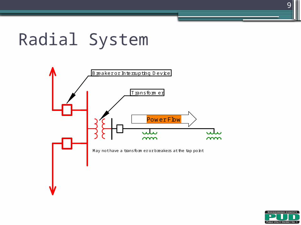
•Radial systems: A group of contiguous transmission Elements that emanates from a single point of connection of 100 kV or higher and: ▫a) Only serves Load. Or.. ▫Note - A normally open switching device
between radial systems, as depicted on prints or one-line diagrams for example, does not affect this exclusion
Load Service Exclusions
9
Radial System
Power FlowPower Flow
May not have a transformer or breakers at the tap point
Breaker or Interrupting Device
Transformer
10
•“Local Networks (LN): A group of contiguous transmission Elements operated at or above 100 kV but less than 300 kV that distribute power to Load rather than transfer bulk power across the interconnected system. LN’s emanate from multiple points of connection at 100 kV or higher to improve the level of service to retail customer Load and not to accommodate bulk power transfer across the interconnected system”
Load Service Exclusions
11
• The LN is characterized by all of the following: ▫b) Power flows only into the LN and the LN does not
transfer energy originating outside the LN for delivery through the LN; and
▫c) Not part of a Flowgate or transfer path: The LN does not contain a monitored Facility of a permanent Flowgate in the Eastern Interconnection, a major transfer path within the Western Interconnection, or a comparable monitored Facility in the ERCOT or Quebec Interconnections, and is not a monitored Facility included in an Interconnection Reliability Operating Limit (IROL).
LN Characteristics
12
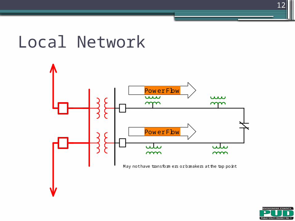
Local Network
Power Flow
Power Flow
May not have transformers or breakers at the tap point
Antitrust/Competition Commercial Damages Environmental Litigation and Regulation Forensic Economics Intellectual Property International Arbitration International Trade Product Liability Regulatory Finance and Accounting Risk Management Securities Tax Utility Regulatory Policy and Ratemaking Valuation Electric Power Financial Institutions Natural Gas Petroleum Pharmaceuticals, Medical Devices, and Biotechnology Telecommunications and Media Transportation
Copyright © 2012 The Brattle Group, Inc. www.brattle.com
FERC’s Seven-Factor Test
Presented by:Philip Hanser
June 13, 2012
14
Agenda
Overview of FERC’s Seven-Factor Test
Application of the Test by State Commissions
Application of the Test by FERC
Takeaways
15
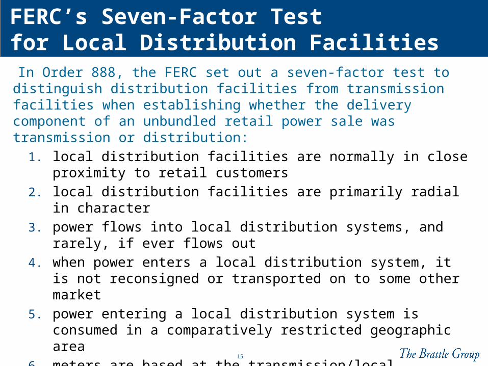
FERC’s Seven-Factor Test for Local Distribution Facilities In Order 888, the FERC set out a seven-factor test to distinguish distribution facilities from transmission facilities when establishing whether the delivery component of an unbundled retail power sale was transmission or distribution:
1. local distribution facilities are normally in close proximity to retail customers
2. local distribution facilities are primarily radial in character
3. power flows into local distribution systems, and rarely, if ever flows out
4. when power enters a local distribution system, it is not reconsigned or transported on to some other market
5. power entering a local distribution system is consumed in a comparatively restricted geographic area
6. meters are based at the transmission/local distribution interface to measure flow into the local distribution system
7. local distribution systems will be of reduced voltage
16
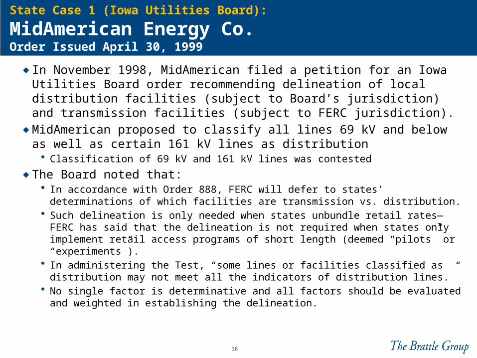
State Case 1 (Iowa Utilities Board):
MidAmerican Energy Co. Order Issued April 30, 1999
♦ In November 1998, MidAmerican filed a petition for an Iowa Utilities Board order recommending delineation of local distribution facilities (subject to Board’s jurisdiction) and transmission facilities (subject to FERC jurisdiction).
♦ MidAmerican proposed to classify all lines 69 kV and below as well as certain 161 kV lines as distribution
• Classification of 69 kV and 161 kV lines was contested
♦ The Board noted that:• In accordance with Order 888, FERC will defer to states’ determinations of
which facilities are transmission vs. distribution.• Such delineation is only needed when states unbundle retail rates—FERC
has said that the delineation is not required when states only implement retail access programs of short length (deemed “pilots” or “experiments”).
• In administering the Test, “some lines or facilities classified as distribution may not meet all the indicators of distribution lines.”
• No single factor is determinative and all factors should be evaluated and weighted in establishing the delineation.
17
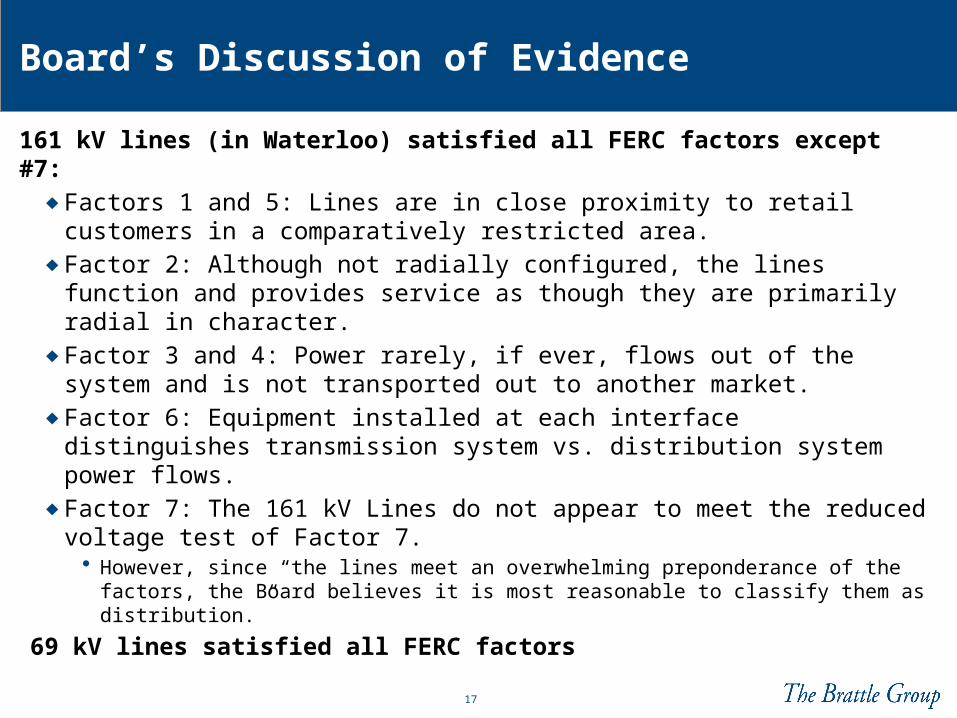
Board’s Discussion of Evidence
161 kV lines (in Waterloo) satisfied all FERC factors except #7: ♦ Factors 1 and 5: Lines are in close proximity to retail customers in
a comparatively restricted area. ♦ Factor 2: Although not radially configured, the lines function and
provides service as though they are primarily radial in character.♦ Factor 3 and 4: Power rarely, if ever, flows out of the system and
is not transported out to another market.♦ Factor 6: Equipment installed at each interface distinguishes
transmission system vs. distribution system power flows.♦ Factor 7: The 161 kV Lines do not appear to meet the reduced
voltage test of Factor 7. • However, since “the lines meet an overwhelming preponderance of the
factors, the Board believes it is most reasonable to classify them as distribution.”
69 kV lines satisfied all FERC factors
18
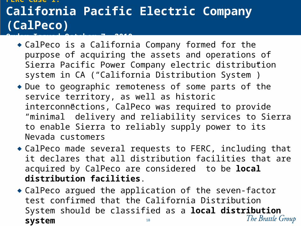
FERC Case 1:
California Pacific Electric Company (CalPeco) Order Issued October 7, 2010
♦ CalPeco is a California Company formed for the purpose of acquiring the assets and operations of Sierra Pacific Power Company electric distribution system in CA (“California Distribution System”)
♦ Due to geographic remoteness of some parts of the service territory, as well as historic interconnections, CalPeco was required to provide “minimal” delivery and reliability services to Sierra to enable Sierra to reliably supply power to its Nevada customers
♦ CalPeco made several requests to FERC, including that it declares that all distribution facilities that are acquired by CalPeco are considered to be local distribution facilities.
♦ CalPeco argued the application of the seven-factor test confirmed that the California Distribution System should be classified as a local distribution system
19
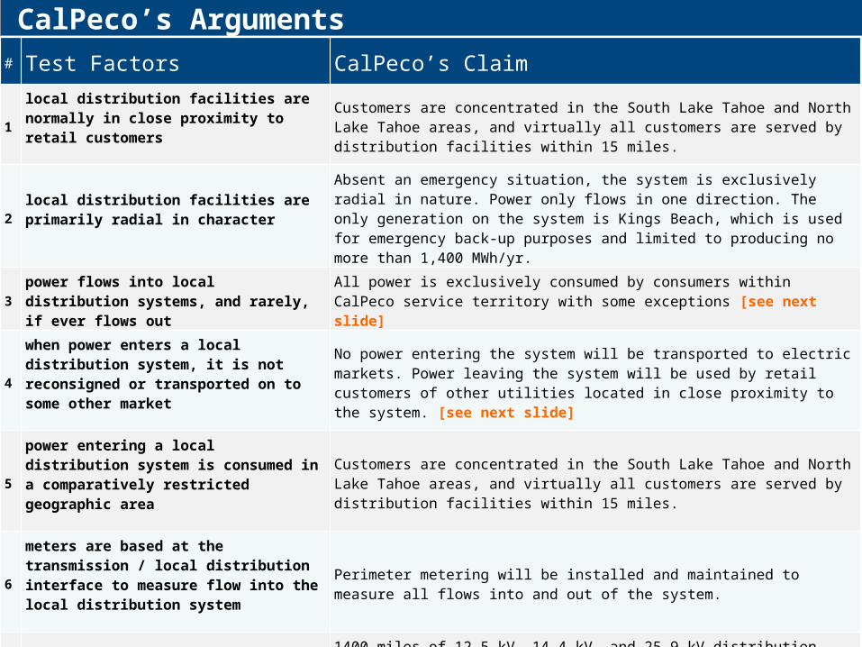
CalPeco’s Arguments# Test Factors CalPeco’s Claim
1local distribution facilities are normally in close proximity to retail customers
Customers are concentrated in the South Lake Tahoe and North Lake Tahoe areas, and virtually all customers are served by distribution facilities within 15 miles.
2local distribution facilities are primarily radial in character
Absent an emergency situation, the system is exclusively radial in nature. Power only flows in one direction. The only generation on the system is Kings Beach, which is used for emergency back-up purposes and limited to producing no more than 1,400 MWh/yr.
3power flows into local distribution systems, and rarely, if ever flows out
All power is exclusively consumed by consumers within CalPeco service territory with some exceptions [see next slide]
4
when power enters a local distribution system, it is not reconsigned or transported on to some other market
No power entering the system will be transported to electric markets. Power leaving the system will be used by retail customers of other utilities located in close proximity to the system. [see next slide]
5
power entering a local distribution system is consumed in a comparatively restricted geographic area
Customers are concentrated in the South Lake Tahoe and North Lake Tahoe areas, and virtually all customers are served by distribution facilities within 15 miles.
6
meters are based at the transmission / local distribution interface to measure flow into the local distribution system
Perimeter metering will be installed and maintained to measure all flows into and out of the system.
7local distribution systems will be of reduced voltage
1400 miles of 12.5 kV, 14.4 kV, and 25.9 kV distribution circuits, 75 miles of 60 kV distribution lines, and 19 miles of 120 kV distribution lines. FERC has not established a definition of what constitutes a reduced voltage distribution line. The limited nature of the three 120 kV distribution lines, combined with the fact that the remaining lines are 60kV or below, satisfies Factor 7.
20
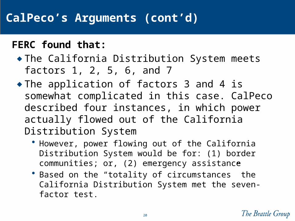
CalPeco’s Arguments (cont’d)
FERC found that:♦ The California Distribution System meets factors 1, 2, 5, 6,
and 7♦ The application of factors 3 and 4 is somewhat complicated
in this case. CalPeco described four instances, in which power actually flowed out of the California Distribution System
• However, power flowing out of the California Distribution System would be for: (1) border communities; or, (2) emergency assistance
• Based on the “totality of circumstances” the California Distribution System met the seven-factor test.
21
FERC Case 2:
City of Pella, IowaOrder Issued February 2, 2011
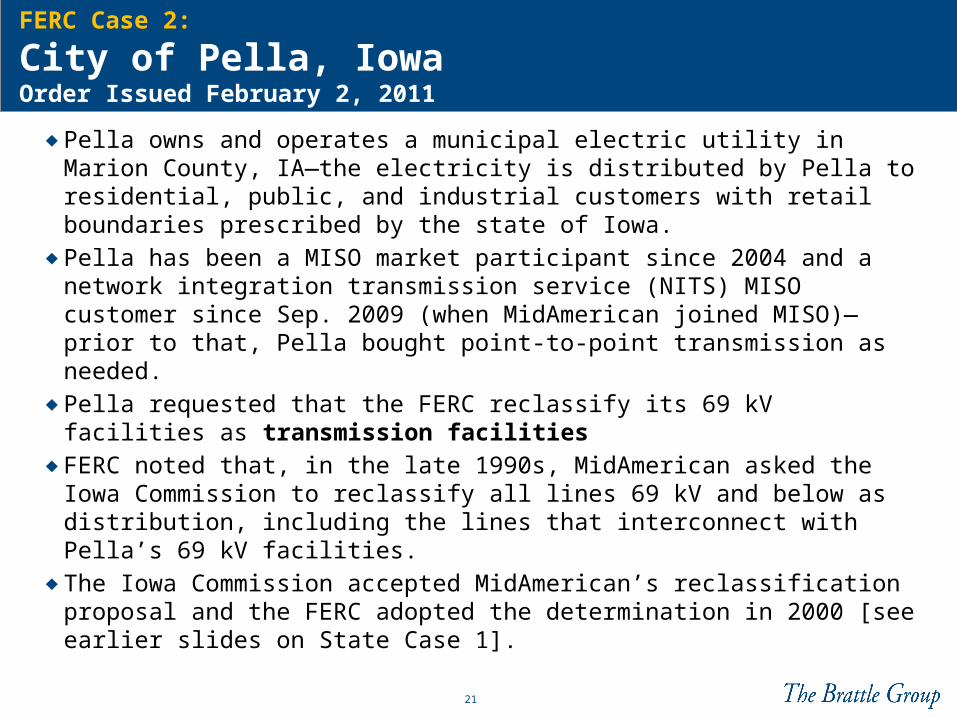
♦ Pella owns and operates a municipal electric utility in Marion County, IA—the electricity is distributed by Pella to residential, public, and industrial customers with retail boundaries prescribed by the state of Iowa.
♦ Pella has been a MISO market participant since 2004 and a network integration transmission service (NITS) MISO customer since Sep. 2009 (when MidAmerican joined MISO)—prior to that, Pella bought point-to-point transmission as needed.
♦ Pella requested that the FERC reclassify its 69 kV facilities as transmission facilities
♦ FERC noted that, in the late 1990s, MidAmerican asked the Iowa Commission to reclassify all lines 69 kV and below as distribution, including the lines that interconnect with Pella’s 69 kV facilities.
♦ The Iowa Commission accepted MidAmerican’s reclassification proposal and the FERC adopted the determination in 2000 [see earlier slides on State Case 1].
22
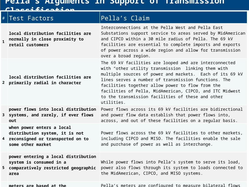
Pella’s Arguments in Support of Transmission Classification# Test Factors Pella’s Claim
1local distribution facilities are normally in close proximity to retail customers
Interconnections at the Pella West and Pella East Substations support service to areas served by MidAmerican and CIPCO within a 30 mile radius of Pella. The 69 kV facilities are essential to complete imports and exports of power across a wide region and allow for transmission over a broad region.
2local distribution facilities are primarily radial in character
The 69 kV facilities are looped and are interconnected with “other utility transmission” linking them with multiple sources of power and markets. Each of its 69 kV lines serves a number of transmission functions. The facilities together allow power to flow from the facilities of Pella, MidAmerican, CIPCO, and ITC Midwest to the transmission facilities of these and other utilities.
3power flows into local distribution systems, and rarely, if ever flows out
Power flows across its 69 kV facilities are bidirectional and power flow data establish that power flows into, across, and out of these facilities on a regular basis.
4
when power enters a local distribution system, it is not reconsigned or transported on to some other market
Power flows across the 69 kV facilities to other markets, including CIPCO and MISO. The facilities enable the sale and purchase of power as well as interchange.
5
power entering a local distribution system is consumed in a comparatively restricted geographic area
While power flows into Pella’s system to serve its load, power also flows through its system to loads connected to the MidAmerican, CIPCO, and MISO systems.
6
meters are based at the transmission / local distribution interface to measure flow into the local distribution system
Pella’s meters are configured to measure bilateral flows and used for billing for transmission by the local balancing authority. These meters are used to validate billing for wholesale transactions among utilities and to determine energy and ancillary services with MISO.
7local distribution systems will be of reduced voltage
Local distribution system operate at a reduced voltage (typically 12.47 kV) compared to Pella’s elevated 69 kV transmission facilities.
23
Pella’s Arguments (cont’d)
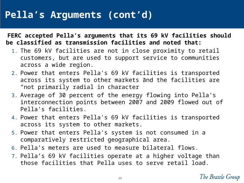
FERC accepted Pella’s arguments that its 69 kV facilities should be classified as transmission facilities and noted that:
1. The 69 kV facilities are not in close proximity to retail customers, but are used to support service to communities across a wide region.
2. Power that enters Pella's 69 kV facilities is transported across its system to other markets and the facilities are “not primarily radial in character”
3. Average of 30 percent of the energy flowing into Pella's interconnection points between 2007 and 2009 flowed out of Pella's facilities.
4. Power that enters Pella's 69 kV facilities is transported across its system to other markets.
5. Power that enters Pella's system is not consumed in a comparatively restricted geographical area.
6. Pella’s meters are used to measure bilateral flows.
7. Pella’s 69 kV facilities operate at a higher voltage than those facilities that Pella uses to serve retail load.
24
Takeaways
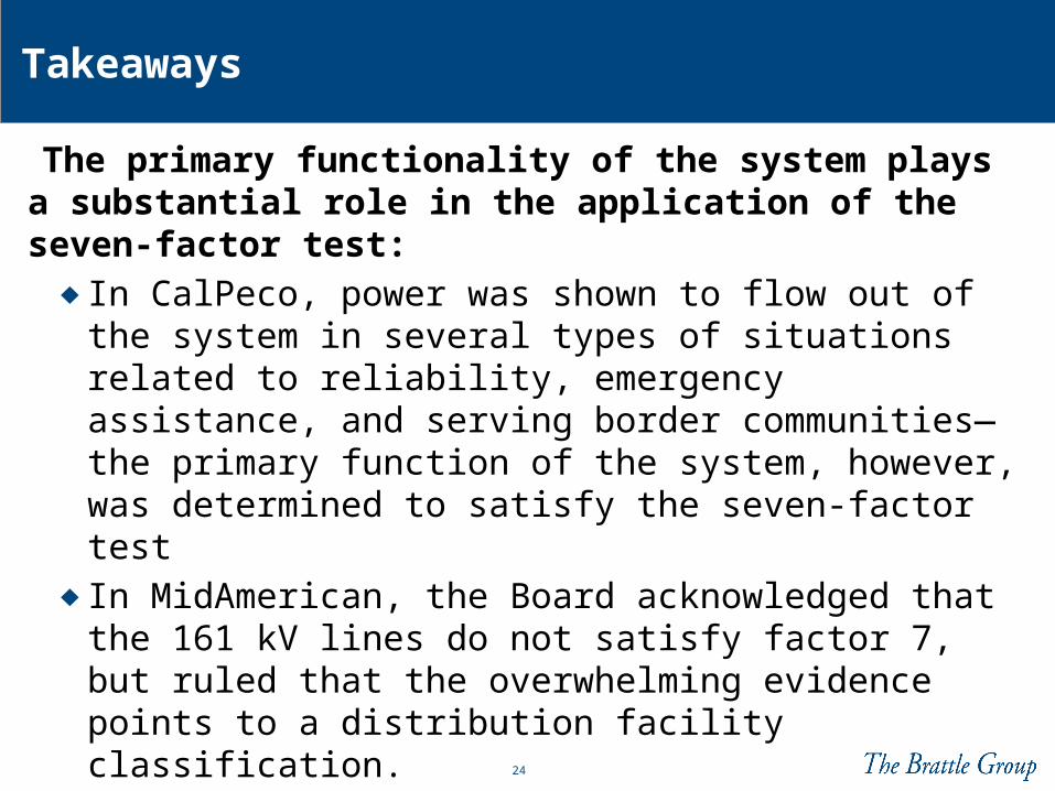
The primary functionality of the system plays a substantial role in the application of the seven-factor test:
♦ In CalPeco, power was shown to flow out of the system in several types of situations related to reliability, emergency assistance, and serving border communities—the primary function of the system, however, was determined to satisfy the seven-factor test
♦ In MidAmerican, the Board acknowledged that the 161 kV lines do not satisfy factor 7, but ruled that the overwhelming evidence points to a distribution facility classification.
♦ In Pella, FERC reclassified MidAmerican’s 69kV lines to transmission on the basis of Pella’s demonstrating they primarily performed transmission functions
25
•Examples of BPA Transmission and Distribution systems▫BPA Radial System▫BPA Radial (Open Loop)▫BPA LN (Radial in Character)▫BPA BES Network (Part of a Transfer Path)▫BPA BES Network or Distribution?
•Methodology for Consideration
PART 2
26
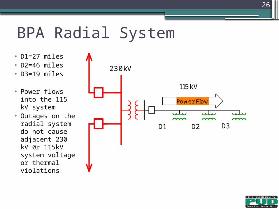
• D1=27 miles• D2=46 miles• D3=19 miles
• Power flows into the 115 kV system
• Outages on the radial system do not cause adjacent 230 kV 0r 115kV system voltage or thermal violations
BPA Radial System
Power Flow
230kV
115kV
D1 D2 D3
27
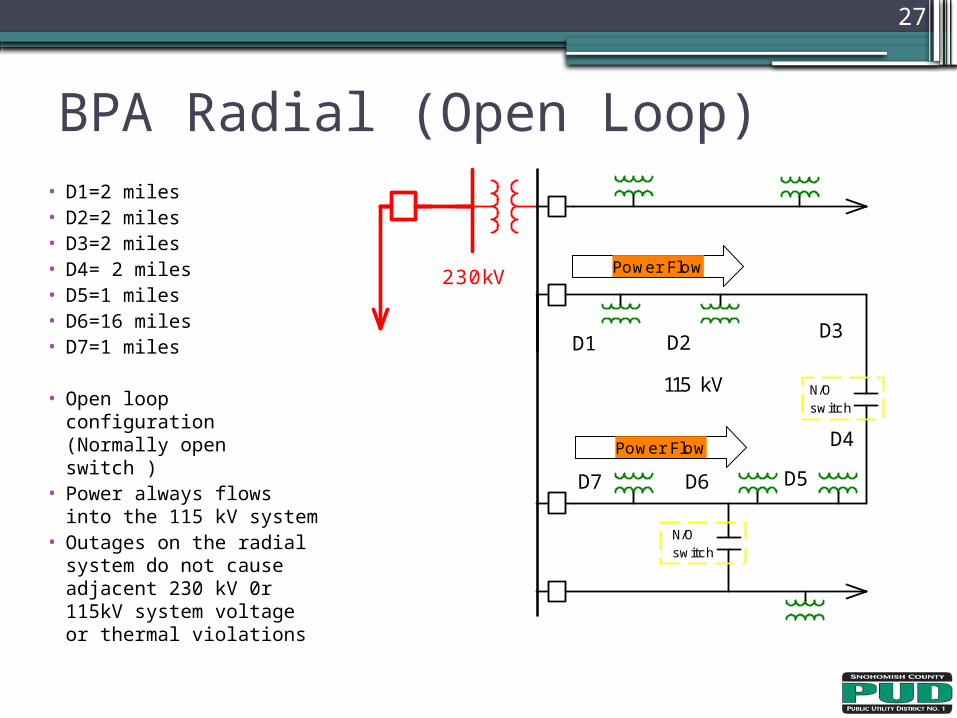
• D1=2 miles• D2=2 miles• D3=2 miles• D4= 2 miles• D5=1 miles• D6=16 miles• D7=1 miles
• Open loop configuration (Normally open switch )
• Power always flows into the 115 kV system
• Outages on the radial system do not cause adjacent 230 kV 0r 115kV system voltage or thermal violations
BPA Radial (Open Loop)
Power Flow
Power Flow
115 kV
N/Oswitch
N/Oswitch
D1 D2 D3
D5
D4
D7 D6
230kV
28
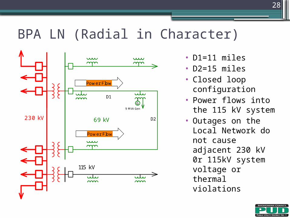
• D1=11 miles• D2=15 miles• Closed loop
configuration• Power flows into
the 115 kV system• Outages on the
Local Network do not cause adjacent 230 kV 0r 115kV system voltage or thermal violations
BPA LN (Radial in Character)
Power Flow
Power Flow
D1
D2230 kV
9 MVA Gen
G
69 kV
115 kV
29
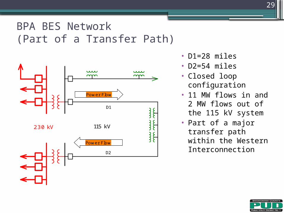
• D1=28 miles• D2=54 miles• Closed loop
configuration• 11 MW flows in and
2 MW flows out of the 115 kV system
• Part of a major transfer path within the Western Interconnection
BPA BES Network(Part of a Transfer Path)
Power Flow
Power Flow
D1
D2
230 kV 115 kV
30
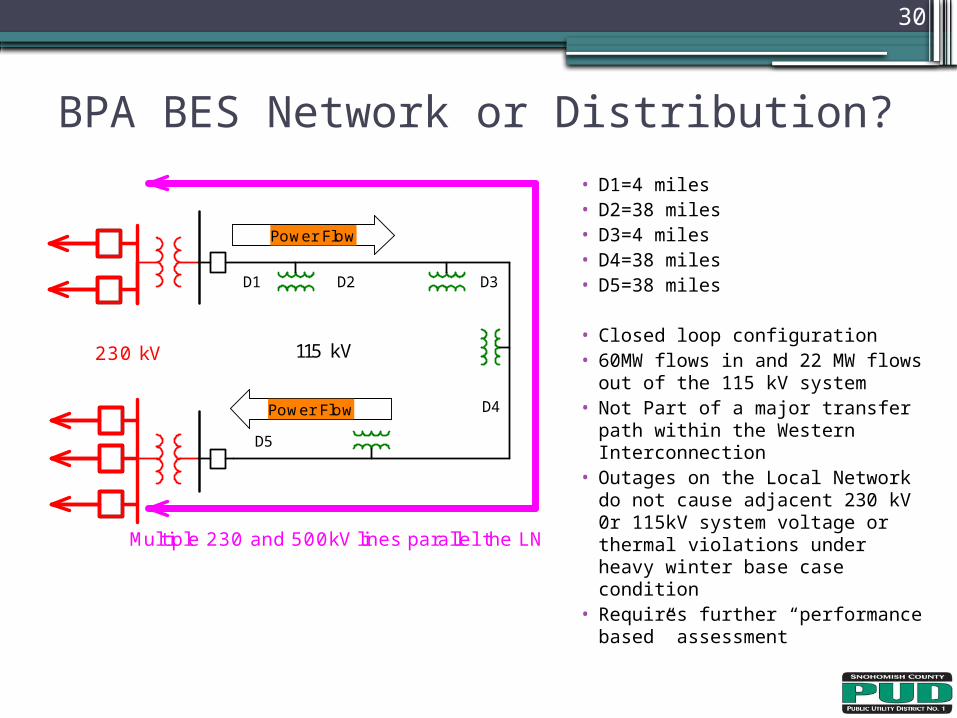
• D1=4 miles• D2=38 miles• D3=4 miles• D4=38 miles• D5=38 miles
• Closed loop configuration• 60MW flows in and 22 MW
flows out of the 115 kV system• Not Part of a major transfer
path within the Western Interconnection
• Outages on the Local Network do not cause adjacent 230 kV 0r 115kV system voltage or thermal violations under heavy winter base case condition
• Requires further “performance based” assessment
BPA BES Network or Distribution?
Power Flow
Power Flow
D2
230 kV 115 kV
D1 D3
D4
D5
Multiple 230 and 500kV lines parallel the LN
31
• Consistent methodology for reliability and commercial purposes▫ Can the facilities adversely or favorably impact neighboring
systems?• Radial systems that do not impact neighboring systems
▫ BPA Radial Systems▫ BPA Radial (Open Loop)▫ BPA Local Network (Radial in Character)
• Networked system that impact neighboring systems▫ BPA BES Network (Part of a Transfer Path)
• Networked system that may or may not impact neighboring systems▫ Use a “performance based” assessment
Methodology for Consideration

32
Thank You