bulk metal foil technology industrial grade miniature ... · bulk metal® foil technology...
TRANSCRIPT
Bulk Metal® Foil Technology Industrial GradeMiniature Voltage Divider with TCR Tracking of
1.5 ppm/°C and Ratio Stability of 0.001 % (10 ppm)
VSR144Vishay Foil Resistors
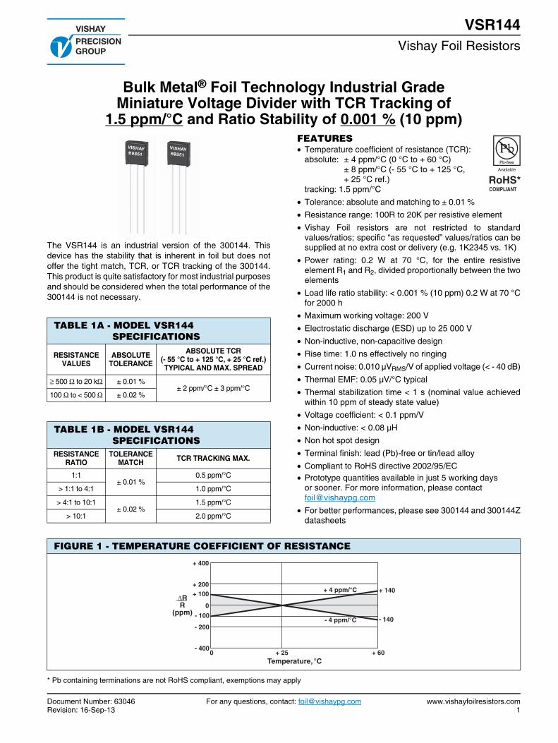
The VSR144 is an industrial version of the 300144. This device has the stability that is inherent in foil but does not offer the tight match, TCR, or TCR tracking of the 300144. This product is quite satisfactory for most industrial purposes and should be considered when the total performance of the 300144 is not necessary.
TABLE 1A - MODEL VSR144 SPECIFICATIONS
RESISTANCE VALUES
ABSOLUTE TOLERANCE
ABSOLUTE TCR(- 55 °C to + 125 °C, + 25 °C ref.)TYPICAL AND MAX. SPREAD
500 to 20 k ± 0.01 %± 2 ppm/°C ± 3 ppm/°C
100 to < 500 ± 0.02 %
TABLE 1B - MODEL VSR144 SPECIFICATIONS
RESISTANCE RATIO
TOLERANCE MATCH TCR TRACKING MAX.
1:1± 0.01 %
0.5 ppm/°C
> 1:1 to 4:1 1.0 ppm/°C
> 4:1 to 10:1± 0.02 %
1.5 ppm/°C
> 10:1 2.0 ppm/°C
FEATURES Temperature coefficient of resistance (TCR):
absolute: ± 4 ppm/°C (0 °C to + 60 °C)± 8 ppm/°C (- 55 °C to + 125 °C,+ 25 °C ref.)
tracking: 1.5 ppm/°C Tolerance: absolute and matching to ± 0.01 % Resistance range: 100R to 20K per resistive element Vishay Foil resistors are not restricted to standard
values/ratios; specific “as requested” values/ratios can be supplied at no extra cost or delivery (e.g. 1K2345 vs. 1K)
Power rating: 0.2 W at 70 °C, for the entire resistive element R1 and R2, divided proportionally between the two elements
Load life ratio stability: < 0.001 % (10 ppm) 0.2 W at 70 °C for 2000 h
Maximum working voltage: 200 V Electrostatic discharge (ESD) up to 25 000 V Non-inductive, non-capacitive design Rise time: 1.0 ns effectively no ringing Current noise: 0.010 µVRMS/V of applied voltage (< - 40 dB) Thermal EMF: 0.05 µV/°C typical Thermal stabilization time < 1 s (nominal value achieved
within 10 ppm of steady state value) Voltage coefficient: < 0.1 ppm/V Non-inductive: < 0.08 µH Non hot spot design Terminal finish: lead (Pb)-free or tin/lead alloy Compliant to RoHS directive 2002/95/EC Prototype quantities available in just 5 working days
or sooner. For more information, please contact [email protected]
For better performances, please see 300144 and 300144Z datasheets
FIGURE 1 - TEMPERATURE COEFFICIENT OF RESISTANCE
+ 400
+ 200
0
- 200
- 4000 + 25
- 140
Temperature, °C
+ 140+ 100
- 100
ΔRR
(ppm)
+ 60
+ 4 ppm/°C
- 4 ppm/°C
* Pb containing terminations are not RoHS compliant, exemptions may apply
Document Number: 63046 For any questions, contact: [email protected] www.vishayfoilresistors.comRevision: 16-Sep-13 1
VSR144Vishay Foil Resistors
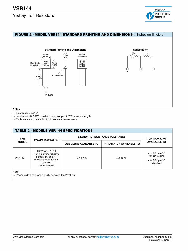
FIGURE 2 - MODEL VSR144 STANDARD PRINTING AND DIMENSIONS in inches (millimeters)
Schematic (2)
2
R2
1
R1
Standard Printing and Dimensions
VFR0125
VSR144 10K
000
0.01
%10
K00
0
1
R1 Indicator
0.295(7.49)
0.320(8.13)
MatchTolerance
Date CodeModel No.
0.751)
(19.05)
0.1 (2.54)
0.1(2.54)
3
Notes• Tolerance: ± 0.010"(1) Lead wires: #22 AWG solder coated copper, 0.75" minimum length(2) Each resistor contains 1 chip of two resistive elements
TABLE 2 - MODELS VSR144 SPECIFICATIONS
VFRMODEL POWER RATING (1)(2)
STANDARD RESISTANCE TOLERANCETCR TRACKING AVAILABLE TO
ABSOLUTE AVAILABLE TO RATIO MATCH AVAILABLE TO
VSR144
0.2 W at + 70 °C(for the entire resistive
element R1 and R2) divided proportionally
betweenthe two values
± 0.02 % ± 0.02 %
< ± 1.5 ppm/°Cfor like values
< ± 2.0 ppm/°Cstandard
Note(1) Power is divided proportionally between the 2 values.
www.vishayfoilresistors.com For any questions, contact: [email protected] Document Number: 630462 Revision: 16-Sep-13

VSR144Vishay Foil Resistors
TABLE 3 - EXAMPLES OF VCODES FOR POPULAR VALUES (other values available on request)
VSR144 RATIOS
VCODES R1 R2 VCODES R1 R2
V0009 20K 20K V0058 2K 20K
V0010 20K 10K V0030 2K 18K
V0100 20K 2K V0029 2K 4K
V0055 19K4 9K7 V0059 2K 2K
V0223 17K5 20K V0103 2K 3K
V0097 15K 15K V0154 1K5 3K
V0001 10K 10K V0032 1K 16K
V0042 10K 8K323 V0121 1K 2K
V0006 10K 2K V0004 1K 1K
V0166 10K 15K V0379 1K 7K
V0226 9K 10K V0374 800R 800R
V0003 9K 1K V0022 511R 16K2
V0013 8K 16K V0091 500R 500R
V0107 6K 20K V0162 500R 15K
V0014 6K 7K V0378 500R 4K5
V0160 6K 6K V0061 300R 300R
V0159 5K5 7K7 V0088 100R 100R
V0005 5K 10K V0380 100R 15K
V0002 5K 5K V0375 100R 12K3
V0373 4K 12K V0381 100R 50R
V0026 3K 19K2 V0377 50R 28K
V0156 3K 6K V0376 35R 20K
V0158 2K7 10K - - -
Note• A combination of these values are available in reverse order and in values up to 5 digits
Document Number: 63046 For any questions, contact: [email protected] www.vishayfoilresistors.comRevision: 16-Sep-13 3

VSR144Vishay Foil Resistors
TABLE 4 - GLOBAL PART NUMBER INFORMATION (1)
NEW GLOBAL PART NUMBER: Y0094V0107QQ9L (preferred part number format)
DENOTES PRECISION RESISTANCE VALUE CODE TOLERANCE MATCH PACKAGING
Y VCODE Q = 0.02 %A = 0.05 %B = 0.1 %D = 0.5 %F = 1.0 %
L = bulk pack
PRODUCT CODE RESISTANCE TOLERANCE CHARACTERISTICS
0094 = VSR144 Q = ± 0.02 %A = ± 0.05 %B = ± 0.1 %D = ± 0.5 %F = ± 1.0 %
0 = standard9 = lead (Pb)-free1 to 999 = custom
FOR EXAMPLE: ABOVE GLOBAL ORDER Y0094 V0107 Q Q 9 L:TYPE: VSR144VALUE: 6K/20KABSOLUTE TOLERANCE: ± 0.02 %TOLERANCE MATCH: ± 0.02 %TERMINATION: lead (Pb)-freePACKAGING: bulk pack
HISTORICAL PART NUMBER: VSR144T 6K/20K TCR2 Q Q B (will continue to be used)
VSR144 T 6K/20K TCR2 Q Q B
MODEL TERMINATION OHMIC VALUETCR
CharacteristicABSOLUTE
TOLERANCETOLERANCE
MATCHPACKAGING
VSR144 T = lead (Pb)-freeNone = tin/lead alloy
R1 = 6.0 kR2 = 20.0 k
Q = ± 0.02 %A = ± 0.05 %B = ± 0.1 %D = ± 0.5 %F = ± 1.0 %
Q = 0.02 %A = 0.05 %B = 0.1 %D = 0.5 %F = 1.0 %
B = bulk pack
Note(1) For non-standard requests, please contact application engineering
0 9 4 V 1 0 70Y 0 9 LQ Q
www.vishayfoilresistors.com For any questions, contact: [email protected] Document Number: 630464 Revision: 16-Sep-13

Vishay Precision Group
Document No.: 63999Revision: 27-Apr-2011
www.vishaypg.com1
Legal Disclaimer Notice
Disclaimer
Legal Disclaimer Notice
Disclaimer
Document No.: 63999Revision: 27-Apr-2011
ALL PRODUCTS, PRODUCT SPECIFICATIONS AND DATA ARE SUBJECT TO CHANGE WITHOUT NOTICE.
Vishay Precision Group, Inc., its affiliates, agents, and employees, and all persons acting on its or their behalf (collectively, “Vishay Precision Group”), disclaim any and all liability for any errors, inaccuracies or incompleteness contained herein or in any other disclosure relating to any product.
The product specifications do not expand or otherwise modify Vishay Precision Group’s terms and conditions of purchase, including but not limited to, the warranty expressed therein.
Vishay Precision Group makes no warranty, representation or guarantee other than as set forth in the terms and conditions of purchase. To the maximum extent permitted by applicable law, Vishay Precision Group disclaims (i) any and all liability arising out of the application or use of any product, (ii) any and all liability, including without limitation special, consequential or incidental damages, and (iii) any and all implied warranties, including warranties of fitness for particular purpose, non-infringement and merchantability.
Information provided in datasheets and/or specifications may vary from actual results in different applications and performance may vary over time. Statements regarding the suitability of products for certain types of applications are based on Vishay Precision Group’s knowledge of typical requirements that are often placed on Vishay Precision Group products. It is the customer’s responsibility to validate that a particular product with the properties described in the product specification is suitable for use in a particular application.
No license, express, implied, or otherwise, to any intellectual property rights is granted by this document, or by any conduct of Vishay Precision Group.
The products shown herein are not designed for use in life-saving or life-sustaining applications unless otherwise expressly indicated. Customers using or selling Vishay Precision Group products not expressly indicated for use in such applications do so entirely at their own risk and agree to fully indemnify Vishay Precision Group for any damages arising or resulting from such use or sale. Please contact authorized Vishay Precision Group personnel to obtain written terms and conditions regarding products designed for such applications.
Product names and markings noted herein may be trademarks of their respective owners.