bull novascale 4040
TRANSCRIPT

Bull NovaScale 4040User’s Guide
86 A1 26EG 03
ORDER REFERENCE


Bull NovaScale 4040User’s Guide
Hardware
May 2005
BULL CEDOC
357 AVENUE PATTON
B.P.20845
49008 ANGERS CEDEX 01
FRANCE
86 A1 26EG 03
ORDER REFERENCE

The following copyright notice protects this book under the Copyright laws of the United States of America
and other countries which prohibit such actions as, but not limited to, copying, distributing, modifying, and
making derivative works.
Copyright Bull S.A. 2003, 2005
Printed in France
Suggestions and criticisms concerning the form, content, and presentation of
this book are invited. A form is provided at the end of this book for this purpose.
To order additional copies of this book or other Bull Technical Publications, you
are invited to use the Ordering Form also provided at the end of this book.
Trademarks and Acknowledgements
We acknowledge the right of proprietors of trademarks mentioned in this book.
Intel) and Itanium) are registered trademarks of Intel Corporation.
Windows) and Microsoft) software are registered trademarks of Microsoft Corporation.
UNIX) is a registered trademark in the United States of America and other countries licensed exclusively
through the Open Group.
Linux) is a registered trademark of Linus Torvalds.
The information in this document is subject to change without notice. Bull will not be liable for errors contained
herein, or for incidental or consequential damages in connection with the use of this material.
Contents iii
Contents
Preface ................................................................................................................. 1Regulatory Specifications and Disclaimers ..............................................................................3
Declaration of the Manufacturer or Importer ..................................................................3
1 System Description........................................................................................ 7Introduction...............................................................................................................................7Chassis Description..................................................................................................................8External Chassis Features .......................................................................................................9
Chassis Front .................................................................................................................9Chassis Back ...............................................................................................................16Chassis Top .................................................................................................................19
Internal Chassis Features ......................................................................................................20Power Subsystem ........................................................................................................20Cooling Subsystem ......................................................................................................22
2 Board Set Description.................................................................................. 23System Board Set ..................................................................................................................24
Processor Board ..........................................................................................................25Processor Overview .....................................................................................................26Memory Boards ............................................................................................................26I/O Board......................................................................................................................27Midplane Board ............................................................................................................28Front Panel Board ........................................................................................................28SCSI Backplane Board.................................................................................................28
Peripherals .............................................................................................................................29External SCSI Connector (Optional) ............................................................................29Add-In Board Slots .......................................................................................................29
Video 30SCSI Controller ......................................................................................................................30ICH4 IDE Controller................................................................................................................30Server Management...............................................................................................................31
Baseboard Management Controller (BMC) ..................................................................31QLogic GEM359 SCSI Hot-swap Controller.................................................................32
3 Configuration Software and Utilities .......................................................... 33Power-on Sequence and Power-on Self-Test (POST)...........................................................33The Extensible Firmware Interface (EFI) Boot Manager ........................................................33The Extensible Firmware Interface (EFI) Shell.......................................................................37Using BIOS Setup ..................................................................................................................40
Starting Setup ..............................................................................................................40Record Your Setup Settings.........................................................................................40Navigating Setup Utility Screens..................................................................................41Primary Screens...........................................................................................................41
LSI SCSI Utility.......................................................................................................................49
iv NovaScale 4040 User’s Guide
The NovaScale 4040 Resource CD .......................................................................................56Running Software Utilities Directly from the Resource CD ..........................................56
System Maintenance Utility ....................................................................................................57Remote Keyboard Navigation ......................................................................................58Local Keyboard Navigation ..........................................................................................58About Box Information..................................................................................................59Server Discovery ..........................................................................................................60Remote SMU Application .............................................................................................60Local SMU Application .................................................................................................62Shutdown SMU Application..........................................................................................63Server Management Configuration Task......................................................................64SEL Viewer...................................................................................................................95SDR Viewer................................................................................................................100FRU Viewer ................................................................................................................104Task Error Handling ...................................................................................................107Help .....................................................................................................................108
Shutting Down the Server ....................................................................................................111EFI Platform Diagnostic Tests..............................................................................................112
Starting the Application ..............................................................................................112Understanding the General User Interface.................................................................113Understanding Basic Testing .....................................................................................113Enabling Tests For Execution ....................................................................................113Setting Test Options...................................................................................................114Interpreting Results ....................................................................................................114Getting Help On Individual Tests................................................................................114Viewing System Information.......................................................................................114Viewing the Test Log..................................................................................................115
EFI Service Partition.............................................................................................................115Service Partition Requirements..................................................................................115Installing Service Partition Files .................................................................................115Installation Requirements...........................................................................................116Installing the Files ......................................................................................................116Booting the Server from the Service Partition ............................................................117
Console Redirection .............................................................................................................117Operation ...................................................................................................................118Keystroke Mappings...................................................................................................118Limitations ..................................................................................................................120Interface to Server Management................................................................................121
Terminal Mode Overview .....................................................................................................122Setup and Configuration ............................................................................................122Security Information ...................................................................................................126Terminal Mode Commands ........................................................................................126Hex-ASCII Command Format ....................................................................................128Text Command Format ..............................................................................................129Terminal Mode IPMI Message Bridging .....................................................................129
Contents v
4 Hot-swapping System Components......................................................... 141Tools and Supplies Needed .................................................................................................141
Equipment Log ...........................................................................................................141Hot-swapping System Fans .................................................................................................141Hot-swapping Hard Disk Drives ...........................................................................................143
Determining Drive Status ...........................................................................................143Removing a Hard Disk Drive ......................................................................................143Installing a Hard Disk Drive ........................................................................................144
Hot-swapping Power Supplies .............................................................................................144Determining Power Supply Status..............................................................................145Removing a Power Supply .........................................................................................146Installing a Power Supply ...........................................................................................147
Hot Plugging PCI Add-in Cards............................................................................................148Removing Hot-plug PCI Add-in Cards........................................................................148Installing Hot-plug PCI Add-in Cards..........................................................................150
A Equipment Log and Configuration Worksheet........................................ 153Equipment Log .....................................................................................................................153
B Warnings ..................................................................................................... 155Warning: English (USA) ......................................................................................................157AVERTISSEMENTS : Français...........................................................................................159WARNUNG: Deutsch ..........................................................................................................161AVVERTENZA: Italiano.......................................................................................................163ADVERTENCIA: Español....................................................................................................165
C INI File Format ............................................................................................ 167Introduction...........................................................................................................................167
INI File Structure ........................................................................................................167The [INF_FILE] Section..............................................................................................167The [DISPLAY] Section ..............................................................................................167
D SDRViewer Splash Screen File Format.................................................... 171
E SELViewer Splash Screen File Format .................................................... 173
F Glossary ...................................................................................................... 175
G Troubleshooting ......................................................................................... 177
Index ................................................................................................................. 179
vi NovaScale 4040 User’s Guide
FiguresFigure 1. NovaScale 4040 Front View ...................................................................................................... 7
Figure 2. Chassis Front View.................................................................................................................... 9
Figure 3. Front Panel Controls and Indicators...................................................................................... 10
Figure 4. Peripheral Bay.......................................................................................................................... 12
Figure 5. Hard Disk Drive Carrier ........................................................................................................... 13
Figure 6. DVD/CD-ROM and LS-240 Drive Carriers .............................................................................. 14
Figure 7. Location of Processor/Memory Subsystem Serviceability Indicators ............................... 15
Figure 8. Chassis Back Features............................................................................................................ 16
Figure 9. Back Panel View Showing Indicator and Switch Locations ................................................ 17
Figure 10. Power Supply Indicators ....................................................................................................... 18
Figure 11. I/O Subsystem Serviceability Indicators ............................................................................. 19
Figure 12. Fan Status Indicators ............................................................................................................ 22
Figure 13. Server System Block Diagram.............................................................................................. 23
Figure 14. LSI SCSI Utility Main Menu ................................................................................................... 50
Figure 15. Adapter Properties................................................................................................................. 51
Figure 16. Device Properties................................................................................................................... 52
Figure 17. Device Properties Format Option......................................................................................... 53
Figure 18. Device Properties Verify Option........................................................................................... 53
Figure 19. Adapter and/or Device Properties Exit Menu...................................................................... 54
Figure 20. SCSI Utility Exit Menu............................................................................................................ 54
Figure 21. SMU Application About Box .................................................................................................. 59
Figure 22. SMU Application About Box (Advanced button selected).................................................. 59
Figure 23. Service Partition Utilities........................................................................................................ 61
Figure 24. SMU Home ............................................................................................................................... 62
Figure 25. LAN Channel Configuration................................................................................................... 65
Figure 26. LAN Alert Configuration......................................................................................................... 68
Figure 27. New / Edit LAN Alert ............................................................................................................... 69
Figure 28. Serial Over LAN Configuration.............................................................................................. 71
Figure 29. User Configuration ................................................................................................................. 73
Contents vii
Figure 30. Edit User Configuration.......................................................................................................... 74
Figure 31. Platform Event Filter Configuration ...................................................................................... 76
Figure 32. Event Filter Settings ............................................................................................................... 78
Figure 33. Edit Event Filter Settings ....................................................................................................... 79
Figure 34. Alert Policy Configuration...................................................................................................... 81
Figure 35. Edit Alert Policy Entry ............................................................................................................ 82
Figure 36. Serial / Modem Channel Configuration................................................................................. 84
Figure 37. Modem Mode Configuration .................................................................................................. 86
Figure 38. Destination Dial Settings........................................................................................................ 88
Figure 39. New / Edit Dial String.............................................................................................................. 89
Figure 40. Page Destination Configuration ............................................................................................ 90
Figure 41. Edit Page Destination ............................................................................................................. 91
Figure 42. Terminal Mode Configuration ................................................................................................ 92
Figure 43. Power Configuration............................................................................................................... 94
Figure 44. SEL Viewer, Hex Display Mode.............................................................................................. 96
Figure 45. SDR Viewer ............................................................................................................................ 101
Figure 46. FRU Viewer ............................................................................................................................ 105
Figure 47. Remote SMU Help Window (browser based) ..................................................................... 108
Figure 48. SMU Local Help Window ...................................................................................................... 110
Figure 49. Opening the Back Top Cover.............................................................................................. 142
Figure 50. System Fan Location and Removal ................................................................................... 142
Figure 51. Removing a Hard Disk Drive............................................................................................... 143
Figure 52. Power Supply Installation Order ........................................................................................ 144
Figure 53. Removing a Power Supply.................................................................................................. 146
Figure 54. Installing a Power Supply ................................................................................................... 147
Figure 55. Removing a Hot-plug PCI Add-in Card .............................................................................. 149
Figure 56. Installing a Hot-plug PCI Add-in Card................................................................................ 151
viii NovaScale 4040 User’s Guide
TablesTable 1. Server Physical Specifications ................................................................................................... 7
Table 2. Chassis Feature Summary .......................................................................................................... 8
Table 3. Front Panel Control and Indicator Description ....................................................................... 10
Table 4. SCSI Hard Drive LED Details ..................................................................................................... 13
Table 5. Processor/Memory Subsystem Serviceability Indicator Details ........................................... 15
Table 6. Power Supply LED Status Indicators ....................................................................................... 18
Table 7. Boot Maintenance Menu Options.............................................................................................. 34
Table 8. EFI Shell Commands.................................................................................................................. 38
Table 9. Using Setup Screens.................................................................................................................. 41
Table 10. BIOS Setup Main Screen Menu Items..................................................................................... 42
Table 11. Processor Configuration Submenu Items ............................................................................. 43
Table 12. BIOS Setup Advanced Screen Menu Items............................................................................ 44
Table 13. BIOS Setup Security Screen Menu Items............................................................................... 45
Table 14. BIOS Setup System Management Screen Menu Items......................................................... 46
Table 15. Setup Console Redirection Sub Menu Items......................................................................... 47
Table 16. BIOS Setup Exit Screen Menu Items ...................................................................................... 48
Table 17. Keyboard Support for Remote SMU Client ............................................................................ 58
Table 18. Keyboard Support for Local SMU Client................................................................................ 58
Table 19. Common Buttons for Configuration Management Sub-tasks ............................................. 64
Table 20. SEL Sort Order Definitions ...................................................................................................... 97
Table 21. SDR Type Name Format......................................................................................................... 102
Table 22. Non-ASCII Key Mappings ...................................................................................................... 119
Table 23. ASCII Key Mappings............................................................................................................... 120
Table 24. Terminal Mode Request to BMC ........................................................................................... 128
Table 25. Terminal Mode Request from BMC....................................................................................... 128
Table 26. Supported BMC Combinations for IPMI Message Bridging............................................... 129
Table 27. Terminal Mode Text Commands ........................................................................................... 130
Table 28. Boot Option Parameters ........................................................................................................ 134
Table 29. Terminal Mode Configuration................................................................................................ 140
Contents ix
Table 30. SCSI Drive Status LED Descriptions .................................................................................... 143
Table 31. Power Supply LEDs................................................................................................................ 145
Table 32. Equipment Log........................................................................................................................ 153
Table 33. Data Markers ........................................................................................................................... 169
Table 34. SDRViewer Splash Screen File Format ................................................................................ 171
Table 35. Splash Screen File Section Keywords for the SEL.INI ....................................................... 173
Table 36. SELViewer Splash Screen File Format................................................................................. 174
Table 37. Symptom/Cause/Solution Troubleshooting Guide ............................................................. 177

x NovaScale 4040 User’s Guide
Preface 1
Preface
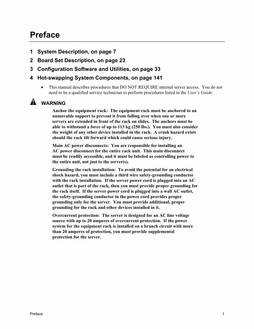
1 System Description, on page 72 Board Set Description, on page 233 Configuration Software and Utilities, on page 33
4 Hot-swapping System Components, on page 141• This manual describes procedures that DO NOT REQUIRE internal server access. You do not
need to be a qualified service technician to perform procedures listed in the User’s Guide.
WARNINGAnchor the equipment rack: The equipment rack must be anchored to anunmovable support to prevent it from falling over when one or moreservers are extended in front of the rack on slides. The anchors must beable to withstand a force of up to 113 kg (250 lbs.). You must also considerthe weight of any other device installed in the rack. A crush hazard existsshould the rack tilt forward which could cause serious injury.
Main AC power disconnects: You are responsible for installing anAC power disconnect for the entire rack unit. This main disconnectmust be readily accessible, and it must be labeled as controlling power tothe entire unit, not just to the server(s).
Grounding the rack installation: To avoid the potential for an electricalshock hazard, you must include a third wire safety-grounding conductorwith the rack installation. If the server power cord is plugged into an ACoutlet that is part of the rack, then you must provide proper grounding forthe rack itself. If the server power cord is plugged into a wall AC outlet,the safety-grounding conductor in the power cord provides propergrounding only for the server. You must provide additional, propergrounding for the rack and other devices installed in it.
Overcurrent protection: The server is designed for an AC line voltagesource with up to 20 amperes of overcurrent protection. If the powersystem for the equipment rack is installed on a branch circuit with morethan 20 amperes of protection, you must provide supplementalprotection for the server.

2 NovaScale 4040 User’s Guide
WARNING – POWER CORD RATINGDo not attempt to modify or use an AC power cord that is not the exacttype required. You must use a power cord that meets the followingcriteria:� Rating: For U.S./Canada cords must be UL Listed/CSA Certified,
16/3, 75C type, VW-1, SJT/SVT, with NEMA 5-15P orNEMA 6-15P attachment plug and IEC 320 C13 input powerconnector rated 15 amps. For outside U.S./Canada cords must beflexible harmonized (<HAR>) rated 250 V, 1.0 mm minimumconductor size with IEC 320 C13 input power connector and ratedfor no less than 10 amps.
� Input Power Connector, server end: The connectors that plug intothe AC receptacles on the server must be an IEC 320, sheet C13,type female connector and are rated for 125 V/250 V, 15 A.
� Cord length and flexibility: Cords must be less than 4.5 meters(14.76 feet) long.
The Server power units must be connected to the Power Distribution Unit(PDU) located at the back of the Cabinet. Use the power cords provided withthe PDU. Connect the power cord to the outlet in the front of the PDU. DONOT use the outlets at the rear of the PDU.
CAUTIONTemperature: The range of temperatures in which the server operates wheninstalled in an equipment rack, must not go below 10 °C (50 °F) or rise above35 °C (95 °F). Extreme fluctuations in temperature can cause a variety ofproblems in your server.
Ventilation: The equipment rack must provide sufficient airflow to the frontof the server to maintain proper cooling. The rack must also includeventilation sufficient to exhaust a maximum of 1500 W (5,100 BTU/hr) forthe server. The rack selected and the ventilation provided must be suitable tothe environment in which the server will be used.

Preface 3
Regulatory Specifications and Disclaimers
Declaration of the Manufacturer or ImporterWe hereby certify that this product is in compliance with European Union EMC Directive89/336/EEC, using standards EN55022 (Class A) and EN55024 and Low Voltage Directive73/23/EEC, Standard EN60950.
Safety ComplianceUSA: UL 1950 – 3rd Edition/CSA 22.2. No. 950-M93Canada: UL Certified – 3rd Edition/CSA 22.2. No. 950-M93 for Canada (product bears
the single UL mark for U.S. and Canada)Europe: Low Voltage Directive, 73/23/EECTUV/GS to EN60950 2nd Edition with
Amendments, A1 = A2 + A3 + A4International: TUV/CB to IEC 60950 3rd Edition, EN60 950 2nd Edition + Amd 1-4, EMKO-TSE
(74-SEC) 207/94 plus international deviationsAustralian / New Zealand: CB Report to IEC 60950, 3rd Edition plus Australian deviations
Electromagnetic Compatibility (EMC)USA: FCC CFR 47 Part 2 and 15, Verified Class A LimitCanada: IC ICES-003 Class A LimitEurope: EMC Directive, 89/336/EEC:
• EN55022, Class A Limit, Radiated & Conducted Emissions• EN55024, ITE Specific Immunity Standard• EN61000-4-2, ESD Immunity (Level 2 Contact Discharge, Level 3 Air Discharge)• EN61000-4-3, Radiated Immunity (Level 2)• EN61000-4-4, Electrical Fast Transient (Level 2)• EN61000-4-5, AC Surge• EN61000-4-6, Conducted RF• EN61000-4-8, Power Frequency Magnetic Fields• EN61000-4-11, Voltage Dips and Interrupts• EN61000-3-2, Limit for Harmonic Current Emissions• EN61000-3-3, Voltage Flicker
Japan: VCCI Class A ITE (CISPR 22, Class A Limit) IEC 1000-3-2 Limit for HarmonicCurrent Emissions
Australia/New Zealand: AS/NZS 3548, Class ATaiwan: BSMI Approval, Class AKorea: RRL Approval, Class ARussia: GOST ApprovedInternational: CISPR 22, Class A Limit

4 NovaScale 4040 User’s Guide
FCC Electromagnetic Compatibility Notice (USA)This equipment has been tested and found to comply with the limits for a Class A digital device,pursuant to Part 15 of the FCC Rules. These limits are designed to provide reasonable protectionagainst harmful interference when the equipment is operating in a commercial environment. Thisequipment generates, uses, and can radiate radio frequency energy and, if not installed and used inaccordance with the instructions, may cause harmful interference to radio communications.Operation of this equipment in a residential area is likely to cause harmful interference. In thiscase, the user is required to correct the interference at the users own expense. If this equipmentdoes cause harmful interference to radio or television reception, which can be determined byturning the equipment off and on; the user is encouraged to try to correct the interference by one ormore of the following measures:• Reorient or relocate the receiving antenna.• Increase the separation between the equipment and the receiver.• Connect the equipment into an outlet on a circuit different from that to which the receiver is
connected.• Consult the dealer or an experienced radio/TV technician for help.
Any changes or modifications not expressly approved by the grantee of this device could void theuser’s authority to operate the equipment. The customer is responsible for ensuring compliance ofthe modified product.
FCC Declaration of ConformityProduct Type: NovaScale 4040
This device complies with Part 15 of the FCC Rules. Operation is subject to the following twoconditions: (1) This device may not cause harmful interference, and (2) this device must accept anyinterference received, including interference that may cause undesired operation.
For questions related to the EMC performance of this product, contact your Service Representative.
Laser Compliance NoticeThis product uses laser technology complying with Class 1 laser requirements.
Class 1 Laser ProductLuokan 1 LaserlaiteKlasse 1 Laser ApparatLaser Klasse 1

Preface 5
Electromagnetic Compatibility Notices (International)Europe (CE Declaration of Conformity)
This product has been tested in accordance too, and complies with the Low Voltage Directive(73/23/EEC) and EMC Directive (89/336/EEC). The product has been marked with the CE Markto illustrate its compliance.
Japan EMC Compatibility
English translation of the notice above:This is a Class A product based on the standard of the Voluntary Control Council for Interferenceby Information Technology Equipment (VCCI). If this equipment is used in a domesticenvironment, radio disturbance may arise. When such trouble occurs, the user may be required totake corrective actions.
ICES-003 (Canada)
Cet appareil numérique respecte les limites bruits radioélectriques applicables aux appareilsnumériques de Classe A prescrites dans la norme sur le matériel brouilleur: “AppareilsNumériques”, NMB-003 édictée par le Ministre Canadian des Communications.
English translation of the notice above:This digital apparatus does not exceed the Class A limits for radio noise emissions from digitalapparatus set out in the interference-causing equipment standard entitled “Digital Apparatus,”ICES-003 of the Canadian Department of Communications.
BSMI (Taiwan)The BSMI Certification number and the following warning is located on the product safety labelwhich is located visibly on the external chassis.

6 NovaScale 4040 User’s Guide
System Description 7
1 System Description
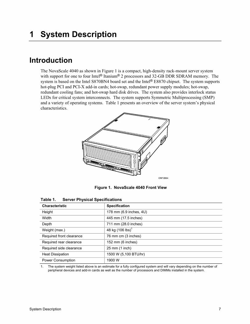
IntroductionThe NovaScale 4040 as shown in Figure 1 is a compact, high-density rack-mount server systemwith support for one to four Intel® Itanium® 2 processors and 32-GB DDR SDRAM memory. Thesystem is based on the Intel S870BN4 board set and the Intel® E8870 chipset. The system supportshot-plug PCI and PCI-X add-in cards; hot-swap, redundant power supply modules; hot-swap,redundant cooling fans; and hot-swap hard disk drives. The system also provides interlock statusLEDs for critical system interconnects. The system supports Symmetric Multiprocessing (SMP)and a variety of operating systems. Table 1 presents an overview of the server system’s physicalcharacteristics.
Figure 1. NovaScale 4040 Front View
Table 1. Server Physical SpecificationsCharacteristic SpecificationHeight 178 mm (6.9 inches, 4U)Width 445 mm (17.5 inches)Depth 711 mm (28.0 inches)Weight (max.) 48 kg (106 lbs)1
Required front clearance 76 mm cm (3 inches)Required rear clearance 152 mm (6 inches)Required side clearance 25 mm (1 inch)Heat Dissipation 1500 W (5,100 BTU/hr)Power Consumption 1900 W
1. The system weight listed above is an estimate for a fully configured system and will vary depending on the number ofperipheral devices and add-in cards as well as the number of processors and DIMMs installed in the system.
8 NovaScale 4040 User’s Guide
Chassis DescriptionThe chassis provides a modularized processor/memory subsystem, I/O subsystem, and peripheralbay. Other features are outlined in Table 2.
Table 2. Chassis Feature SummaryFeature CommentServerConfiguration
• Stand-alone system including external I/O PCI slots and disk expansion as needs grow• Supports Intel Itanium 2 processors• 32-GB Double Data Rate (DDR) Synchronous Dynamic Random Access Memory
(SDRAM) memory support with 2-GB DIMMsExpansion andServicing
• Front access to hot-swap hard disk drives• Three hot-swap 1-inch Ultra320 SCSI hard disk drives• Rear access to hot-swap power supplies• Two hot-swap 1200-W power supplies in a redundant (1+1, 220 V) configuration with
redundant power cords (one per power supply)• Four top access hot-swap system fans in a redundant (3+1) configuration• Dockable processor/memory subsystem, I/O subsystem and peripheral bay• Dockable slim-line LS-240 and DVD/CD-ROM drives• Interlock status indicator LEDs for major modules• Eight 64-bit hot-plug PCI-X slots
Management • Remote management through LAN or modem• Emergency Management Port• Intelligent Platform Management Interface (IPMI) 1.5 compliant• Wired for Management (WfM) 2.0 compliant• Remote diagnostics support through LAN or modem
Upgrades • Field upgradeable to the next generation Itanium processor family• Multi-generational chassis
System-levelscalability
• Up to 32-GB DDR SDRAM• One to four Intel Itanium 2 processors• External I/O (8 PCI slots) and disk expansion• External SCSI connector
System Description 9
External Chassis FeaturesSystem controls and indicators are located in several places on the chassis as follows:• Chassis front:
Front panel: Front panel switches and LEDs Peripheral bay: Hard disk drive LEDs Processor/memory module: Subsystem serviceability LEDs
• Chassis back: Power supply modules (See “Power Subsystem” on page 20 for details) Hot-plug Indicator Board (HPIB)
• Chassis top: I/O subsystem Fan bay (See “Cooling Subsystem” on page 22 for details)
Each of these areas is discussed in this section.
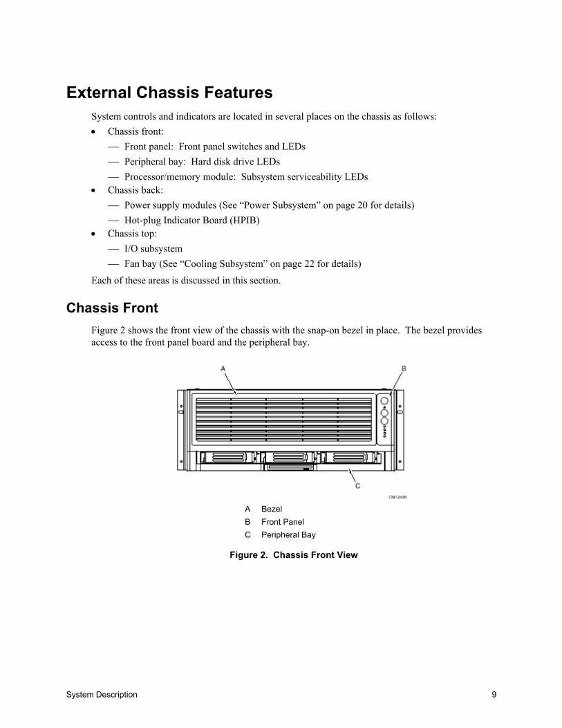
Chassis FrontFigure 2 shows the front view of the chassis with the snap-on bezel in place. The bezel providesaccess to the front panel board and the peripheral bay.
A BezelB Front PanelC Peripheral Bay
Figure 2. Chassis Front View
10 NovaScale 4040 User’s Guide
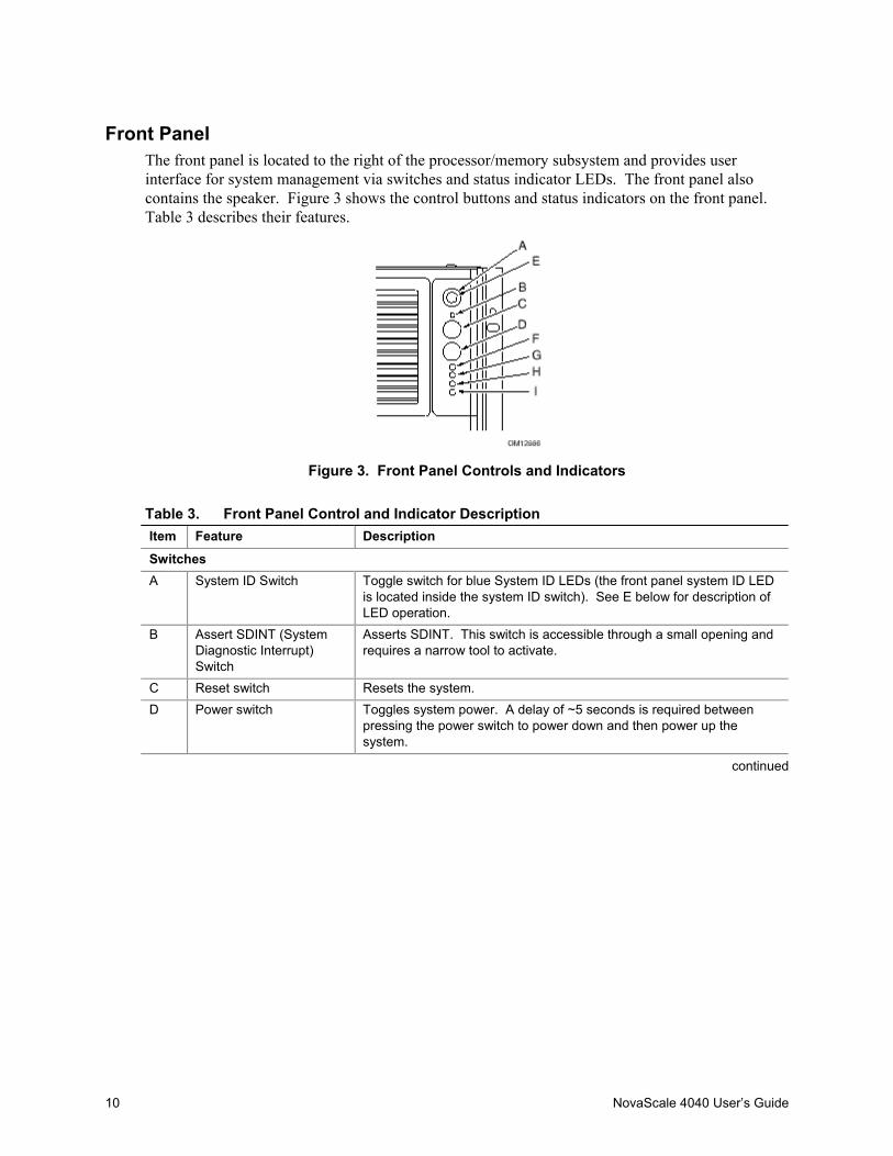
Front PanelThe front panel is located to the right of the processor/memory subsystem and provides userinterface for system management via switches and status indicator LEDs. The front panel alsocontains the speaker. Figure 3 shows the control buttons and status indicators on the front panel.Table 3 describes their features.
Figure 3. Front Panel Controls and Indicators
Table 3. Front Panel Control and Indicator DescriptionItem Feature Description
SwitchesA System ID Switch Toggle switch for blue System ID LEDs (the front panel system ID LED
is located inside the system ID switch). See E below for description ofLED operation.
B Assert SDINT (SystemDiagnostic Interrupt)Switch
Asserts SDINT. This switch is accessible through a small opening andrequires a narrow tool to activate.
C Reset switch Resets the system.D Power switch Toggles system power. A delay of ~5 seconds is required between
pressing the power switch to power down and then power up thesystem.
continued

System Description 11
Table 3. Front Panel Control and Indicator Description (continued)Item Feature DescriptionLED IndicatorsE System ID (Blinking or
Solid Blue). The systemID LEDs are locatedinside the system IDswitch on the front paneland on the back panel
Identifies the system. The system ID is activated either by the systemID switch or through server management software.Pressing the system ID switch once turns on the LEDs solid blue.Press the system ID switch again, the solid blue LEDs turn off.Remove activation - LEDs turn on blinking for 4 minutes (max). Thesystem ID LEDs cannot be turned off by pressing the switch.
F Main Power (Solid orBlinking Green)
A continuously lit LED indicates the presence of DC power in thesystem. The LED goes out when the power is turned off or the powersource is disrupted. Blinking Green indicates the system is in sleepmode.
G Power Fault (SolidAmber)
Indicates any system power faults. Off indicates power is OK.
H Cooling Fault (SolidAmber)
Indicates any system cooling faults. Off indicates system cooling is OK.
I General Fault (Solidamber)
Indicates a system failure. Off indicates system is OK.
12 NovaScale 4040 User’s Guide
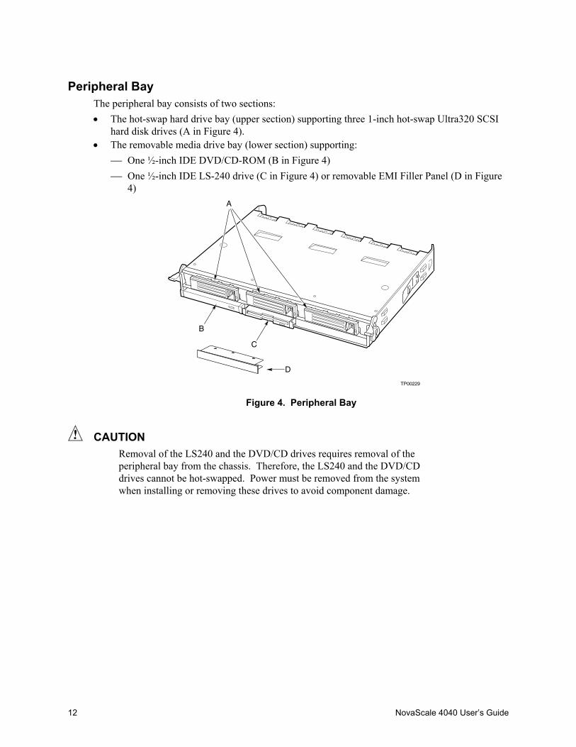
Peripheral BayThe peripheral bay consists of two sections:• The hot-swap hard drive bay (upper section) supporting three 1-inch hot-swap Ultra320 SCSI
hard disk drives (A in Figure 4).• The removable media drive bay (lower section) supporting:
One ½-inch IDE DVD/CD-ROM (B in Figure 4) One ½-inch IDE LS-240 drive (C in Figure 4) or removable EMI Filler Panel (D in Figure
4)
TP00229
A
B
C
D
Figure 4. Peripheral Bay
CAUTIONRemoval of the LS240 and the DVD/CD drives requires removal of theperipheral bay from the chassis. Therefore, the LS240 and the DVD/CDdrives cannot be hot-swapped. Power must be removed from the systemwhen installing or removing these drives to avoid component damage.

System Description 13
Hot-swap Hard Disk Drive BayThe hot-swap hard disk drive carrier (see Figure 5) is designed to accept 15,000-RPM (and slower)Ultra320 SCSI technology SCA-type hard disk drives.
The peripheral bay is designed to support Low Voltage Differential (LVD) SCSI disk drives only.Single-Ended (SE) SCSI devices are not supported in the peripheral bay. SE drives are onlysupported on the external SCSI connector.
A Carrier latchB Status indicator
Figure 5. Hard Disk Drive Carrier
The carriers contain light-pipes that allow dual color LED indicators to show through the bezel todisplay hard disk drive status as described in Table 4.
Table 4. SCSI Hard Drive LED DetailsFeature DescriptionGreen, flashing Indicates the hard drive is activeYellow/Green flashing Indicates a hard drive fault and hard drive is poweredYellow/Blank flashing Indicates a hard drive fault and hard drive is not poweredNot illuminated Indicates no hard drive is installed in the bay
14 NovaScale 4040 User’s Guide
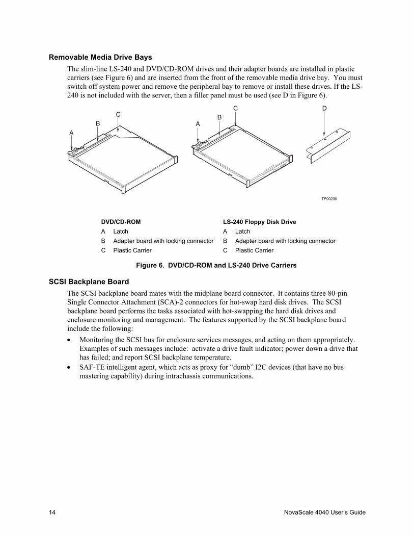
Removable Media Drive BaysThe slim-line LS-240 and DVD/CD-ROM drives and their adapter boards are installed in plasticcarriers (see Figure 6) and are inserted from the front of the removable media drive bay. You mustswitch off system power and remove the peripheral bay to remove or install these drives. If the LS-240 is not included with the server, then a filler panel must be used (see D in Figure 6).
TP00230
A
CB A
CB
D
DVD/CD-ROM LS-240 Floppy Disk DriveA Latch A LatchB Adapter board with locking connector B Adapter board with locking connectorC Plastic Carrier C Plastic Carrier
Figure 6. DVD/CD-ROM and LS-240 Drive Carriers
SCSI Backplane BoardThe SCSI backplane board mates with the midplane board connector. It contains three 80-pinSingle Connector Attachment (SCA)-2 connectors for hot-swap hard disk drives. The SCSIbackplane board performs the tasks associated with hot-swapping the hard disk drives andenclosure monitoring and management. The features supported by the SCSI backplane boardinclude the following:• Monitoring the SCSI bus for enclosure services messages, and acting on them appropriately.
Examples of such messages include: activate a drive fault indicator; power down a drive thathas failed; and report SCSI backplane temperature.
• SAF-TE intelligent agent, which acts as proxy for “dumb” I2C devices (that have no busmastering capability) during intrachassis communications.
System Description 15
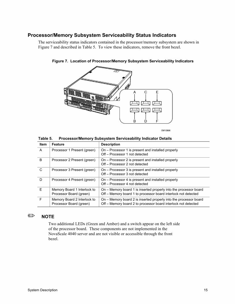
Processor/Memory Subsystem Serviceability Status IndicatorsThe serviceability status indicators contained in the processor/memory subsystem are shown inFigure 7 and described in Table 5. To view these indicators, remove the front bezel.
Figure 7. Location of Processor/Memory Subsystem Serviceability Indicators
Table 5. Processor/Memory Subsystem Serviceability Indicator DetailsItem Feature DescriptionA Processor 1 Present (green) On – Processor 1 is present and installed properly
Off – Processor 1 not detectedB Processor 2 Present (green) On – Processor 2 is present and installed properly
Off – Processor 2 not detectedC Processor 3 Present (green) On – Processor 3 is present and installed properly
Off – Processor 3 not detectedD Processor 4 Present (green) On – Processor 4 is present and installed properly
Off – Processor 4 not detectedE Memory Board 1 Interlock to
Processor Board (green)On – Memory board 1 is inserted properly into the processor boardOff – Memory board 1 to processor board interlock not detected
F Memory Board 2 Interlock toProcessor Board (green)
On – Memory board 2 is inserted properly into the processor boardOff – Memory board 2 to processor board interlock not detected
✏ NOTETwo additional LEDs (Green and Amber) and a switch appear on the left sideof the processor board. These components are not implemented in theNovaScale 4040 server and are not visible or accessible through the frontbezel.
16 NovaScale 4040 User’s Guide
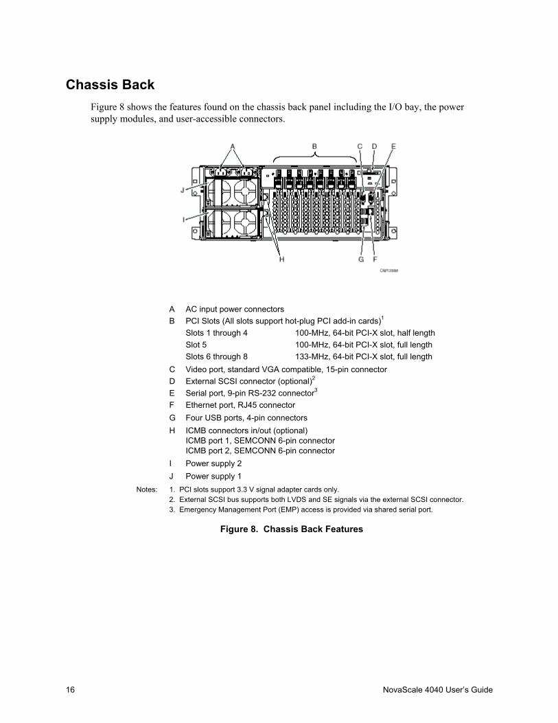
Chassis BackFigure 8 shows the features found on the chassis back panel including the I/O bay, the powersupply modules, and user-accessible connectors.
A AC input power connectorsPCI Slots (All slots support hot-plug PCI add-in cards)1
Slots 1 through 4 100-MHz, 64-bit PCI-X slot, half lengthSlot 5 100-MHz, 64-bit PCI-X slot, full length
B
Slots 6 through 8 133-MHz, 64-bit PCI-X slot, full lengthC Video port, standard VGA compatible, 15-pin connectorD External SCSI connector (optional)2
E Serial port, 9-pin RS-232 connector3
F Ethernet port, RJ45 connectorG Four USB ports, 4-pin connectorsH ICMB connectors in/out (optional)
ICMB port 1, SEMCONN 6-pin connectorICMB port 2, SEMCONN 6-pin connector
I Power supply 2J Power supply 1
Notes: 1. PCI slots support 3.3 V signal adapter cards only.2. External SCSI bus supports both LVDS and SE signals via the external SCSI connector.3. Emergency Management Port (EMP) access is provided via shared serial port.
Figure 8. Chassis Back Features
System Description 17
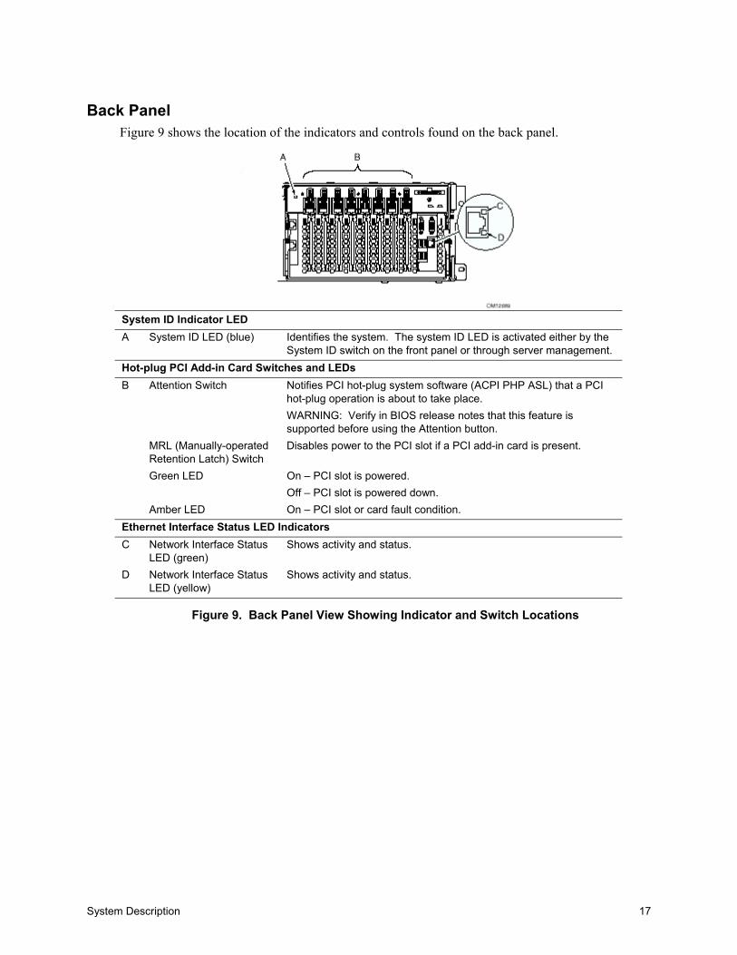
Back PanelFigure 9 shows the location of the indicators and controls found on the back panel.
System ID Indicator LEDA System ID LED (blue) Identifies the system. The system ID LED is activated either by the
System ID switch on the front panel or through server management.Hot-plug PCI Add-in Card Switches and LEDs
Attention Switch Notifies PCI hot-plug system software (ACPI PHP ASL) that a PCIhot-plug operation is about to take place.WARNING: Verify in BIOS release notes that this feature issupported before using the Attention button.
MRL (Manually-operatedRetention Latch) Switch
Disables power to the PCI slot if a PCI add-in card is present.
Green LED On – PCI slot is powered.Off – PCI slot is powered down.
B
Amber LED On – PCI slot or card fault condition.Ethernet Interface Status LED IndicatorsC Network Interface Status
LED (green)Shows activity and status.
D Network Interface StatusLED (yellow)
Shows activity and status.
Figure 9. Back Panel View Showing Indicator and Switch Locations

18 NovaScale 4040 User’s Guide
Power Supply LED IndicatorsEach power supply module has three status LEDs the location and operating conditions for whichare shown in Figure 10.
A Power LED (green) On - indicates the presence of DC power in the systemBlinking - indicates the system is in ACPI sleep modeOff - indicates the power is turned off or the power source isdisrupted
B Failure LED (amber) Indicates a power supply failureC Predictive Failure LED (amber) Indicates a power supply failure is imminent
Figure 10. Power Supply Indicators
Table 6. Power Supply LED Status IndicatorsA(PWR)Power Supply(Green LED)
B(FAIL)Power Supply Fail(Amber LED)
C(PFAIL)Predictive Failure(Amber LED)
No AC power to all PSU OFF OFF OFFNo AC power to this PSU only or PSfailure
OFF OFF ON
AC present / Standby Output On Blinking OFF OFFPower supply DC outputs ON and OK ON OFF OFFCurrent limit ON OFF BlinkingPredictive failure ON Blinking/Latched OFF
✏ NOTEProper system cooling requires that the power supply bay be filled either bytwo power supply modules, or a power supply module and a filler panel.
System Description 19
Chassis Top
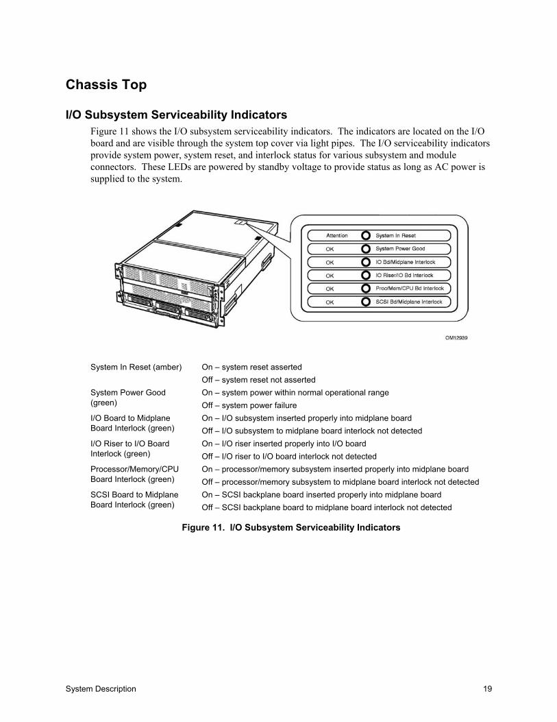
I/O Subsystem Serviceability IndicatorsFigure 11 shows the I/O subsystem serviceability indicators. The indicators are located on the I/Oboard and are visible through the system top cover via light pipes. The I/O serviceability indicatorsprovide system power, system reset, and interlock status for various subsystem and moduleconnectors. These LEDs are powered by standby voltage to provide status as long as AC power issupplied to the system.
System In Reset (amber) On – system reset assertedOff – system reset not asserted
System Power Good(green)
On – system power within normal operational rangeOff – system power failure
I/O Board to MidplaneBoard Interlock (green)
On – I/O subsystem inserted properly into midplane boardOff – I/O subsystem to midplane board interlock not detected
I/O Riser to I/O BoardInterlock (green)
On – I/O riser inserted properly into I/O boardOff – I/O riser to I/O board interlock not detected
Processor/Memory/CPUBoard Interlock (green)
On – processor/memory subsystem inserted properly into midplane boardOff – processor/memory subsystem to midplane board interlock not detected
SCSI Board to MidplaneBoard Interlock (green)
On – SCSI backplane board inserted properly into midplane boardOff – SCSI backplane board to midplane board interlock not detected
Figure 11. I/O Subsystem Serviceability Indicators

20 NovaScale 4040 User’s Guide
Internal Chassis Features
Power Subsystem
WARNINGOnly qualified technical personnel should access the processor, memory,and non-hot-plug I/O subsystem areas while the system is energized assome exposed circuits exceed 240 VA and may cause burn injury ifaccidentally contacted.
The power subsystem can be configured as following:• Two power supply modules installed, (1+1) redundancy at 220 VAC• One power supply module installed, non-redundant at 220 VAC only• Two power supply modules installed, non-redundant for 120 VAC
The power subsystem consists of the following:• Power supply modules• Plug-in DC-to-DC converters• Power pods (located adjacent to the processors on processor board)• The power distribution board
Power Supply ModulesThe power supply modules are Server System Infrastructure (SSI) compliant, universal AC inputwith Power Factor Correction (PFC) Distributed Power Supplies (DPS). The power supplymodules are rated at 1200 W over an input range of 180-264 VAC, and at 700 W over an inputrange of 90-132 VAC.
One power supply module connected to 220 VAC is capable of handling the worst-case powerrequirements for a fully configured system: four processors, 32 GB of memory, eight PCI add-incards, three hard disk drives, a DVD or CD drive, and an LS-240 drive.
The power supply has two DC outputs: 48 V (main) and 12 V (standby). The 48 V main power isdistributed throughout the server and is converted locally at point-of-load using either embedded orplug-in DC-to-DC converters.
In an N+1 configuration the 48 VDC outputs have active (forced) current sharing and 12 VDCSBoutputs have passive current sharing.
The two externally enabled outputs have the following ratings:• +48 VDC at: 24.0 A @HI line /13.5 A @LO line• +12 VDCSB at: 4 A @any line

System Description 21
Redundant AC Power Source OperationEach power supply module requires one power cord to supply AC power to the system. When twopower supply modules and two power cords are installed, the system supports (1+1) power cordredundancy at 220 VAC. This feature allows the system to be powered by two separate ACsources. In this configuration, the system continues to operate without interruption if one of the ACsources fails.
Plug-in DC-to-DC ConvertersTwo types of plug-in DC-to-DC converters are used in the system:• 5 V output• Voltage ID (VID) (2.5 or 3.3 V output)
A control bit set by the board determines output voltage on the VID DC-to-DC converters. TheT-DC-to-DC converters contain an LED for failure indication.
The processor board supports three VID T-DC-to-DC converters (one 3.3 V and two 2.5 V).
The I/O board supports two 5 V and two VID (3.3 V) T-DC-to-DC converters. Each T-DC-to-DCconverter powers a separate plane on the board; therefore all DC-to-DC converter slots must bepopulated.
Processor Power PodsDedicated power pods supply power to each processor. The input connector of the power pod isconnected to the 48 V power on the processor board via a short cable. The output connector of thepower pod mates directly with the processor package.
The Power Distribution BoardThe power distribution board supplies 48 V main and 12 V standby power to all server systemcomponents.
22 NovaScale 4040 User’s Guide
Cooling Subsystem
CAUTIONThe chassis top cover must be installed and closed for proper system cooling.Additionally, cooling components must be hot-swapped within a limited timeperiod. This time period applies only to the time that the cooling componentis physically removed, not from the time of failure.
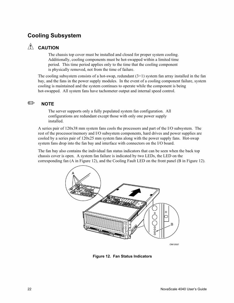
The cooling subsystem consists of a hot-swap, redundant (3+1) system fan array installed in the fanbay, and the fans in the power supply modules. In the event of a cooling component failure, systemcooling is maintained and the system continues to operate while the component is beinghot-swapped. All system fans have tachometer output and internal speed control.
✏ NOTEThe server supports only a fully populated system fan configuration. Allconfigurations are redundant except those with only one power supplyinstalled.
A series pair of 120x38 mm system fans cools the processors and part of the I/O subsystem. Therest of the processor/memory and I/O subsystem components, hard drives and power supplies arecooled by a series pair of 120x25 mm system fans along with the power supply fans. Hot-swapsystem fans drop into the fan bay and interface with connectors on the I/O board.
The fan bay also contains the individual fan status indicators that can be seen when the back topchassis cover is open. A system fan failure is indicated by two LEDs, the LED on thecorresponding fan (A in Figure 12), and the Cooling Fault LED on the front panel (B in Figure 12).
Figure 12. Fan Status Indicators
Board Set Description 23
2 Board Set Description
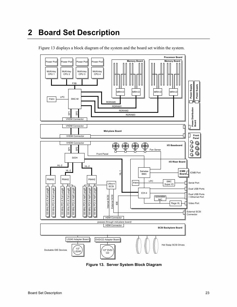
Figure 13 displays a block diagram of the system and the board set within the system.
Processor Board
I/O Baseboard
Mid-plane Board
Power Pod Power Pod Power Pod Power Pod
FSB
SP1
SP2
Memory BoardMemory Board
RDRAM0
RDRAM1
RDRAM2
RDRAM3
SP1
SP2
P64H2 P64H2
VHDM Connector
VHDM Connector
133
MH
z P
CI-X
Ful
l Len
gth
SIOH
HDM Connector
Hot Swap SCSI Drives
LPC
IDE
Inte
rnal
SC
SI
(passes through mid-plane board)
Front Panel
Pow
er D
istri
butio
nB
oard
Pow
er S
uppl
y
Pow
er S
uppl
y
LS240 Adapter Board
1/2"LS240
133
MH
z P
CI-X
Ful
l Len
gth
133
MH
z P
CI-X
Ful
l Len
gth
100
MH
z P
CI-X
Hal
f Len
gth
100
MH
z P
CI-X
Hal
f Len
gth
100
MH
z P
CI-X
Hal
f Len
gth
100
MH
z P
CI-X
Hal
f Len
gth
I/O Riser Board
SahaleeBMC
SMCSuper IO
LPC
Rage XL
82540EMNIC
ICMBBoard ICMB Port
Serial Port
Dual USB Ports
Dual USB Ports+ Ethernet Port
Video Port
Dockable IDE Devices
VHDM Connector
MRH-DMRH-DMRH-DMRH-D
Fan Sense
External SCSIConnector
FWH
ICH-4
Exte
rnal
SC
SI
VHDM Connector
SCSI Backplane BoardHDM Connector
HL-
1
FrontPanel
McKinleyCPU 1
McKinleyCPU 2
McKinleyCPU 3
McKinleyCPU 4
SNC-MFWH
Ultra-4SCSI
HL-2HL-2
HL-2
DVD/CD Adapter Board
1/2" DVD/CD
P64H2
100
MH
z P
CI-X
Ful
l Len
gth
Figure 13. Server System Block Diagram

24 NovaScale 4040 User’s Guide
System Board SetThis section highlights the main features of the board set. The board set contains the following:• Processor board• Two memory boards• I/O board• I/O riser card• Midplane board
In addition, the server contains the following system boards:• Front panel board• SCSI backplane board• Power distribution board• PCI HPIB• Peripheral adapter boards• ICMB Board (optional)
Major components of the board set include:• Intel Itanium 2 processors• Intel E8870 chip set• High-capacity DDR SDRAM memory• High-bandwidth I/O subsystem supporting PCI and PCI-X

Board Set Description 25
Processor BoardThe processor board contains sockets for installing up to four Intel Itanium 2 processors andsupports up to four power pods. It also accepts the memory boards.
The processor board and memory boards are installed horizontally in the processor/memorymodule. The processor/memory module docks into the front of the chassis and mates with themidplane board mounted vertically in the middle of the chassis.
The processor board supports the following:• Sockets for up to four Intel Itanium 2 processors. Two of the processor sockets are mounted on
the secondary side of the processor board.• Provision for up to four 48 V DC-to-DC converter power pods, one for each Intel Itanium 2
processor.• DC-to-DC voltage converters:
Two 48 V to 2.5 V plug-in DC-to-DC converters for DDR memory support One 48 V to 3.3 V plug-in DC-to-DC converter
• Embedded regulators: 3.3 V to 1.2 V 3.3 V to 1.5 V 3.3 V to 1.8 V 1.8 V to 1.3 V linear regulator
• One SNC-M component of the Intel® E8870 chip set.• Three Firmware Hubs (FWH) for BIOS and system configuration utility (SCU) software.• Two memory board connectors that support two Rambus channels each. One memory
connector is mounted on the secondary side of the processor board.• One VHDM 360-pin connector for I/O connections.• One debug port for use with an In-Target Probe (ITP) (debug only).• Two I2C system management buses (SMBus).• Serviceability LEDs.
✏ NOTEThe processor board also contains a switch and two LEDs on the front leftcorner of the primary side of the board that are not used in the NovaScale4040 server.

26 NovaScale 4040 User’s Guide
Processor OverviewEach Intel Itanium 2 processor plugs into a 700-pin Zero Insertion Force (ZIF) socket. Eachprocessor is powered by a 48 V power pod located adjacent to the processor on the processor board.Attached to the top of each processor is a heat sink that dissipates thermal energy.
Memory BoardsThe processor board is designed to support two memory boards (both of which must be installed forthe system to operate). The memory boards are installed on the primary and secondary side of theprocessor board assembly.
The main components of the memory boards are listed hereafter:• Eight 184-pin, DDR-SDRAM DIMM sockets support up to 16 GB of memory using eight
2 GB DIMMs per memory board for a total of 32 GB per system.• Two DMH (DDR Memory Hub) components of the E8870 chip set. This allows two Rambus
channels from the 870-memory controller (SNC-M) to be extended to four DDR channels onthe memory boards. The Rambus channel supports 400 MHz operation and the DDR channelssupport 100 MHz operation.
• An integrated 2.5 V to 1.25 V DC-to-DC converter provides voltage for DDR signaltermination.
• I2C logic.• Field Replaceable Unit (FRU) device ID accessed through a private I2C bus.• Voltage/temperature sensors.
DIMMs must be installed on a memory board in groups of four (a group of four constitutes a row).
CAUTIONDIMMs should only be installed, removed, or replaced by a technicallyqualified person.
CAUTIONThe system does not support mixed-sized DIMMs or DIMMs from differentvendors within the same row.
✏ NOTEThe BIOS automatically detects, sizes, and initializes the memory array,depending on the type, size, and speed of the installed DIMMs. The BIOSreports memory size and allocation to the system through configurationregisters.

Board Set Description 27
I/O BoardThe I/O board is installed horizontally in the I/O bay. The I/O riser card plugs into a connector onthe I/O board. The I/O provides the following features:• Intel E8870 chip set with Scalability Port system interface• Six functionally independent Peripheral Component Interconnect (PCI) bus segments• Three hot-plug 133-MHz, 64-bit PCI-X slots• Five hot-plug 100-MHz, 64-bit PCI-X slots• Integrated dual channel LSI 53C1030 Ultra320 Low Voltage Differential SCSI (LVDS)
controller• I/O riser support connector for I/O interface• On-board power conversion from 48 V bulk power• System reset and clock generation circuits• I2C server management interface• Redundant hot-plug system fan interface
I/O RiserTo conserve space on the I/O board, most system I/O and server management functions have beenplaced on the I/O riser card that plugs into the I/O board. The I/O connectors include video, serial,Local Area Network (LAN), and Universal Serial Bus (USB). The I/O riser:• Contains an IDE bus controller and connector. The IDE bus is routed to the I/O board where it
is further routed to the midplane board’s disk bay connector.• Converts 12 V STDBY (standby) to +5 V STDBY and +3.3 V STDBY and supplies them to
the I/O board.• Mates directly onto the I/O board and together they contain all of the I/O interfaces for the
board set.The I/O riser provides the following features:• One I/O Control Hub 4 (ICH4) component
Four Universal Serial Bus (USB) ports One IDE interface routed through the I/O board connector
• Network Interface Card (NIC) Intel® 82540EM 10/100/1000 Ethernet controller Ethernet port with I2C support
• Low Pin Count (LPC) Super I/O One serial port
• 43 MB of flash memory• Server management controller• Integrated Intelligent Chassis Management Bus (ICMB)• Integrated Rage† XL video controller and memory
Video port Power control - Advanced Configuration and Power Interface (ACPI)
• Speaker control• Integrated standby voltage DC-to-DC converters generating 3.3 V standby and 5 V standby
28 NovaScale 4040 User’s Guide
Midplane BoardThe passive midplane board contains the following features:• VHDM connectors for the processor/memory subsystem and the I/O subsystem• An HDM connector that routes the SCSI bus, two IDE busses, and miscellaneous signals
between the I/O board and the SCSI backplane• Routing of four scalability ports• 48 V power distribution• 12 V standby distribution• 3.3 V standby distribution• 12 V distribution from the SCSI backplane board to the I/O board and power distribution board• Blind-mate power distribution board connector• Blind-mate front panel connector
Front Panel BoardThe front panel board contains switches, LEDs, and the speaker for system interface.
SCSI Backplane BoardThe SCSI backplane board supports three LVDS hard drives. Its features include:• Three SCA connectors for hot-swap 1-inch SCSI hard drives• One blind-mate connector for dockable slim-line IDE LS240 device• One blind-mate connector for dockable slim-line IDE DVD or CD device• SCSI accessed fault-tolerant enclosures (SAF-TE) logic• 48 V to 12 V integrated DC-to-DC converter• 12 V to 5 V integrated DC-to-DC converter• 5 V to 2.5 V linear regulator

Board Set Description 29
PeripheralsThe server connects to supported peripheral devices through interfaces located on the I/O Board.The Super I/O on this board provides four USB ports, an Ethernet port, a serial port, an externalSCSI connector (optional), a VGA video output port, and in and out ICMB connectors (optional).For a detailed view of the I/O Board connections, see Figure 8 on page 16.
External SCSI Connector (Optional)An external SCSI connector is available as an option. A cable runs from the I/O board to theexternal SCSI connector installed on the back panel.
The I/O board contains two Ultra320 compliant SCSI channels. One channel is used internallywhile the other is for external system use. While the internal channel supports only Low VoltageDifferential (LVD) signaling, the external channel supports both LVD and SE (single-ended)signaling. With LVD signaling, the channels can each support a maximum data rate of320 MB/sec.
✏ NOTEThe internal SCSI signal is routed to the midplane board’s disk bayconnector to interface with internal SCSI devices. There is an optionalconnector on that bus that allows an external SCSI controller to drive theinternal bus.
Add-In Board SlotsThe I/O board has three 64-bit/133 MHz hot-plug PCI-X and five 64-bit/100 MHz PCI-Xexpansion slots contained in the following three PCI segments:• P64H2,0 provides for PCI-X slots 1 through 3 (all 100 MHz) and the dual channel LVDS
controller• P64H2,1 provides for PCI-X slots 4 through 6 (two 100 MHz and one 133 MHz)• P64H2,2 provides for PCI-X slots 7 and 8 (both 133 MHz)

30 NovaScale 4040 User’s Guide
VideoThe onboard, integrated ATI RAGE XL 64-bit SVGA chip contains an SVGA controller that isfully compatible with industry video standards. The system comes with 8 MB of 10-nanosecondonboard video memory.
The video controller supports pixel resolutions of up to 1600 x 1200 and up to 16.7 million colors.The controller also provides hardware accelerated bit block transfers of data.
The SVGA controller supports analog VGA monitors (single and multiple frequency, interlacedand noninterlaced) with a maximum vertical retrace noninterlaced frequency of 100 Hz.
The video connector is located on the I/O riser. See Figure 8 on page 16 for the location of thisconnector.
SCSI ControllerA LSI 53C1030 Ultra3 SCSI chip is a highly integrated bus master, dual-channel SCSI I/Oprocessor for SCSI initiator and target applications. The chip supports dual channel, Ultra3(Fast-80) SCSI functionality. This device interfaces the PCI bus to two Ultra3 SCSI buses. The53C1030 is a fully autonomous device, capable of managing multiple I/O operations and associateddata transfers from start to finish without host intervention. The 53C1030 provides powermanagement feature support in accordance with the PCI Bus Power Management InterfaceSpecification.
ICH4 IDE ControllerThe ICH4 IDE controller is a multifunction device on the I/O Board that acts as a PCI-based FastIDE controller. The device controls the following:• PIO and IDE DMA/bus master operations• Mode 4 timing• Transfer rates up to 22 MB/sec (33 MB/sec using ultra DMA transfers)• Buffering for PCI/IDE burst transfers• Master/slave IDE mode

Board Set Description 31
Server ManagementThe server management features are implemented using two micro controllers: the BaseboardManagement Controller (BMC) on the I/O board and the QLogic† GEM359 SCSI hot-swapcontroller on the SCSI backplane board. The ICMB controller is integrated in the BMC andprovides an interface to the external ICMB via the ICMB board.
Baseboard Management Controller (BMC)The Baseboard Management Controller (BMC) and its associated circuitry reside on the I/O risercard. The BMC autonomously monitors system platform management events and logs theiroccurrences in the non-volatile System Event Log (SEL). This includes events such asover-temperature and over-voltage conditions, and fan failures. The BMC can also provide theinterface to the monitored information so system management software can pole and retrieve thepresent status of the platform.
The BMC also provides the interface to the non-volatile ‘Sensor Data Record (SDR) Repository’.Sensor Data Records provide a set of information that system management software can use toautomatically configure itself for the number and type of IPMI sensors (such as temperature andvoltage sensors) in the system.
The following is a list of the major functions of the BMC:• System power control• Platform Event Paging (PEP) / Platform Event Filtering (PEF)• Power distribution board monitoring• Temperature and voltage monitoring• Fan failure monitoring• Processor presence monitoring (no processors installed)• Interlock monitoring• Speaker ‘Beep’ capability on standby and when system is powered up• Intel Itanium 2 processor SEEPROM interface (for processor information ROM [PIROM] and
scratch EEPROM access)• Processor temperature monitoring• Hot-plug PCI slot status reporting• Processor core ratio speed setting• Chassis general fault light control• Chassis cooling failure light control• Chassis power fault light control• Chassis power light control• Chassis ID LEDs control• System Event Log (SEL) interface• Sensor Data Record (SDR) repository interface• SDR/SEL timestamp clock• Board set FRU information interface• Fault resilient booting

32 NovaScale 4040 User’s Guide
• System management watchdog timer• Front panel system diagnostic-interrupt handling• Platform Management Interruption (PMI) / System Diagnostic Interrupt (SDI) status monitor• Event receiver• System interface to the IPMB (via system interface ports)• IPMI Management Controller Initialization Agent (MCIA)• Emergency Management Port (EMP) interface• Serial/modem and LAN alerting
In this platform, the BMC also plays the role of the chassis bridge controller, thus providingintegrated ICMB support. ICMB transports server management information between variouschassis in a cluster configuration that can contain multiple servers and peripherals.
QLogic GEM359 SCSI Hot-swap ControllerThe QLogic GEM359 Hot-swap Controller resides on the SCSI backplane board. The primaryfunctions of the GEM359 are as follows:• Implements the SAF-TE command set• Controls the SCSI Hard Drive fault LEDs• Provides a path for management information via the SCSI• Retrieves hard disk drive fault status, SCSI backplane temperature, and fan failure information
via IPMB• Queries the status of the power distribution board by retrieving information from the BMC
via IPMB• Controls hard disk drive power-on and power-down, facilitating hot-swapping

Configuration Software and Utilities 33
3 Configuration Software and Utilities
Power-on Sequence and Power-on Self-Test (POST)Turning on the system causes POST to run and control to pass to the Boot Manager. From the BootManager, you can choose to invoke the Extensible Firmware Interface (EFI) Shell or you canchoose to go to the Boot Maintenance Menu. For information on the EFI Shell, refer to “TheExtensible Firmware Interface (EFI) Shell” on page 37.
Follow these steps to power up the NovaScale 4040:1. Press the power button on the front control panel. Pressing this button causes the server fans to
start up and POST to begin running. You can monitor boot progress on the video display on amonitor attached to the system.
2. POST, which is stored in flash memory, begins running. POST checks the drive carriers,processors, memory, keyboard, and most installed peripheral devices. During the memory test,POST displays the amount of memory it is able to access and test. The length of time neededto test memory depends on the amount of memory installed.
3. Video appears on the monitor attached to the system and begins to display boot progress. TheAMI BIOS banner displays the loaded versions of the BIOS, PAL, SAL, and EFI.
4. POST concludes and passes control to the boot manager.5. From the boot manager, you can use arrow keys to highlight the option that invokes the EFI
shell operating system (if installed), or you can highlight and select the boot maintenancemenu. Selecting the boot maintenance menu lets you configure boot options and other bootenvironment variables. Booting to the EFI shell causes the following prompt to appear:Shell>
6. When you see this prompt, you can load and start an operating system.
The Extensible Firmware Interface (EFI) Boot ManagerThe EFI boot manager allows you to control the server’s booting environment. Depending on howyou have configured the boot options, after the server is powered up the boot manager presents youwith different ways to bring up the system. For example, you can boot to the EFI Shell, to anoperating system located on the network or residing on media in the server, or to the BootMaintenance Menu.• EFI Shell: A simple, interactive environment that allows EFI device drivers to be loaded, EFI
applications to be launched, and operating systems to be booted. The EFI shell also provides aset of basic commands used to manage files and the system environment variables. For moreinformation on the EFI Shell, refer to “The Extensible Firmware Interface (EFI) Shell” onpage 37.
34 NovaScale 4040 User’s Guide
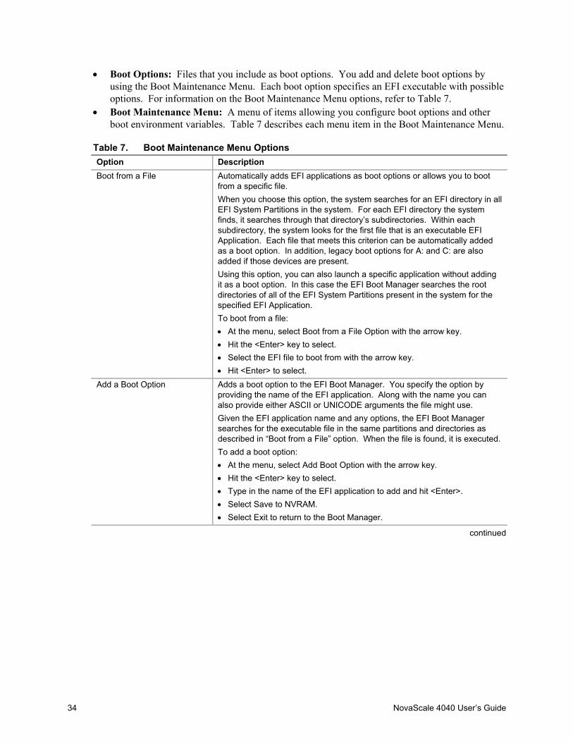
• Boot Options: Files that you include as boot options. You add and delete boot options byusing the Boot Maintenance Menu. Each boot option specifies an EFI executable with possibleoptions. For information on the Boot Maintenance Menu options, refer to Table 7.
• Boot Maintenance Menu: A menu of items allowing you configure boot options and otherboot environment variables. Table 7 describes each menu item in the Boot Maintenance Menu.
Table 7. Boot Maintenance Menu OptionsOption DescriptionBoot from a File Automatically adds EFI applications as boot options or allows you to boot
from a specific file.When you choose this option, the system searches for an EFI directory in allEFI System Partitions in the system. For each EFI directory the systemfinds, it searches through that directory’s subdirectories. Within eachsubdirectory, the system looks for the first file that is an executable EFIApplication. Each file that meets this criterion can be automatically addedas a boot option. In addition, legacy boot options for A: and C: are alsoadded if those devices are present.Using this option, you can also launch a specific application without addingit as a boot option. In this case the EFI Boot Manager searches the rootdirectories of all of the EFI System Partitions present in the system for thespecified EFI Application.To boot from a file:• At the menu, select Boot from a File Option with the arrow key.• Hit the <Enter> key to select.• Select the EFI file to boot from with the arrow key.• Hit <Enter> to select.
Add a Boot Option Adds a boot option to the EFI Boot Manager. You specify the option byproviding the name of the EFI application. Along with the name you canalso provide either ASCII or UNICODE arguments the file might use.Given the EFI application name and any options, the EFI Boot Managersearches for the executable file in the same partitions and directories asdescribed in “Boot from a File” option. When the file is found, it is executed.To add a boot option:• At the menu, select Add Boot Option with the arrow key.• Hit the <Enter> key to select.• Type in the name of the EFI application to add and hit <Enter>.• Select Save to NVRAM.• Select Exit to return to the Boot Manager.
continued

Configuration Software and Utilities 35
Table 7. Boot Maintenance Menu Options (continued)Option DescriptionDelete Boot Options This feature allows you to delete a specific boot option or all boot options.
To delete boot options:• At the menu, select Delete Boot Option with the arrow key.• Hit the <Enter> key to select.• Select the boot option to delete with the arrow key.• Hit <Enter> to select.• Enter <Y> to confirm.• Select Save to NVRAM.• Select Exit to return to the Boot Manager.
Change Boot Order This feature allows you to control the relative order in which the EFI BootManager attempts boot options. For help on the control key sequences youneed for this option, refer to the help menu.To change the boot order:• At the menu, select Change Boot Order with the arrow key.• Select the Option to move with the arrow key.• Hit <u> to move up in the boot order.• Hit <d> to move down in the boot order.• Select Save to NVRAM.• Select Exit to return to the Boot Manager.
Manage BootNext Setting This feature allows you to select a boot option to use one time (the nextboot operation).To manage boot next setting:• At the menu, select Manage Boot Next Setting with the arrow key.• Select the Option to boot next with the arrow key.• Hit <b> to make this option the next boot option.• Hit <r> to reset.• Select Save to NVRAM.• Select Exit to return to the Boot Manager.
Set Auto Boot Timeout This feature allows you to define the value in seconds that pass before thesystem automatically boots without user intervention. Setting this value tozero disables the timeout feature.To set auto boot timeout:• At the menu, select Set Auto Boot Timeout with the arrow key.• Three options are available.• Select the Choose Value option with the arrow key and enter a value of
“0” to disable auto boot.• Select the Delete option with the arrow key and select the Delete setting
with the arrow key and hit <Enter>.• Choose a time out value of 65535 (0xFFFF) to allow you to press any key
while booting to EFI to disable timeout.
continued
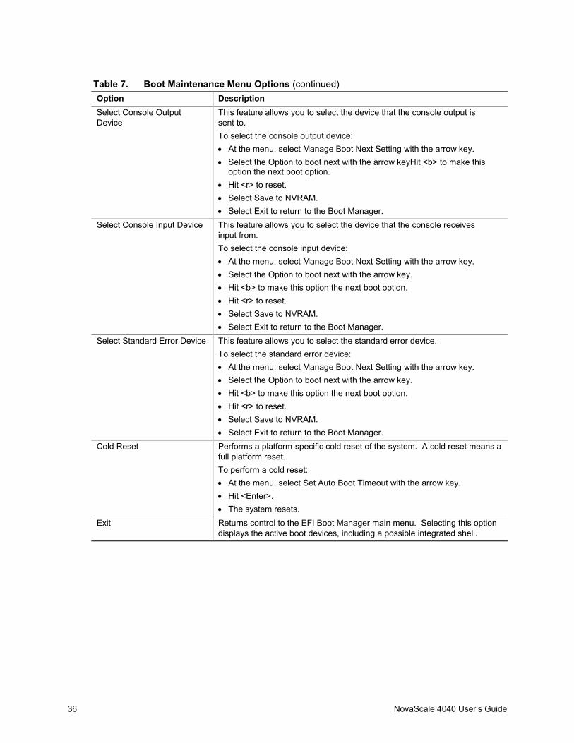
36 NovaScale 4040 User’s Guide
Table 7. Boot Maintenance Menu Options (continued)Option DescriptionSelect Console OutputDevice
This feature allows you to select the device that the console output issent to.To select the console output device:• At the menu, select Manage Boot Next Setting with the arrow key.• Select the Option to boot next with the arrow keyHit <b> to make this
option the next boot option.• Hit <r> to reset.• Select Save to NVRAM.• Select Exit to return to the Boot Manager.
Select Console Input Device This feature allows you to select the device that the console receivesinput from.To select the console input device:• At the menu, select Manage Boot Next Setting with the arrow key.• Select the Option to boot next with the arrow key.• Hit <b> to make this option the next boot option.• Hit <r> to reset.• Select Save to NVRAM.• Select Exit to return to the Boot Manager.
Select Standard Error Device This feature allows you to select the standard error device.To select the standard error device:• At the menu, select Manage Boot Next Setting with the arrow key.• Select the Option to boot next with the arrow key.• Hit <b> to make this option the next boot option.• Hit <r> to reset.• Select Save to NVRAM.• Select Exit to return to the Boot Manager.
Cold Reset Performs a platform-specific cold reset of the system. A cold reset means afull platform reset.To perform a cold reset:• At the menu, select Set Auto Boot Timeout with the arrow key.• Hit <Enter>.• The system resets.
Exit Returns control to the EFI Boot Manager main menu. Selecting this optiondisplays the active boot devices, including a possible integrated shell.

Configuration Software and Utilities 37
The Extensible Firmware Interface (EFI) ShellThe EFI Shell is an EFI application that allows other EFI applications to be launched, EFI devicedrivers to be loaded, and operating systems to be booted. The combination of the EFI firmware andthe EFI Shell provides an environment that can be modified to easily adapt to many differenthardware configurations.
The EFI shell also provides a set of basic commands used to manage files and EFI NVRAM shelland boot variables. A list of these basic commands is shown in Table 8. A more detaileddescription of the commands is available on the EFI website. To obtain the document, navigate tothe http://developer.intel.com/technology/efi URL and click on the Tools hyperlink. Next, click on“EFI Sample Implementation 1.10.14.60” to download the files to your hard drive. Afterdownloading the sample, locate the Microsoft Word file named “EFI1.1ShellCommands.doc.”Descriptions of the EFI shell commands are also available when operating in the EFI Shell bytyping “help” and hitting the <Enter> key.
In addition to the standard shell commands available in the EFI Shell, the EFI environment allowsyou to create your own shell commands and EFI applications. For detailed information about theEFI Shell, its commands, and the ability to develop within the environment, refer to the EFIDeveloper’s Guide. To obtain the document, navigate to thehttp://developer.intel.com/technology/efi URL and click on the Tools hyperlink. Next, click on“EFI Sample Implementation Version 1.02” to download the files to your hard drive. Afterdownloading the sample, locate the Microsoft Word file named “Efi_dg.doc”. To develop yourown shell commands, download the EFI Application Toolkit from the Tools hyperlink on thefollowing website:http://developer.intel.com/technology/efi
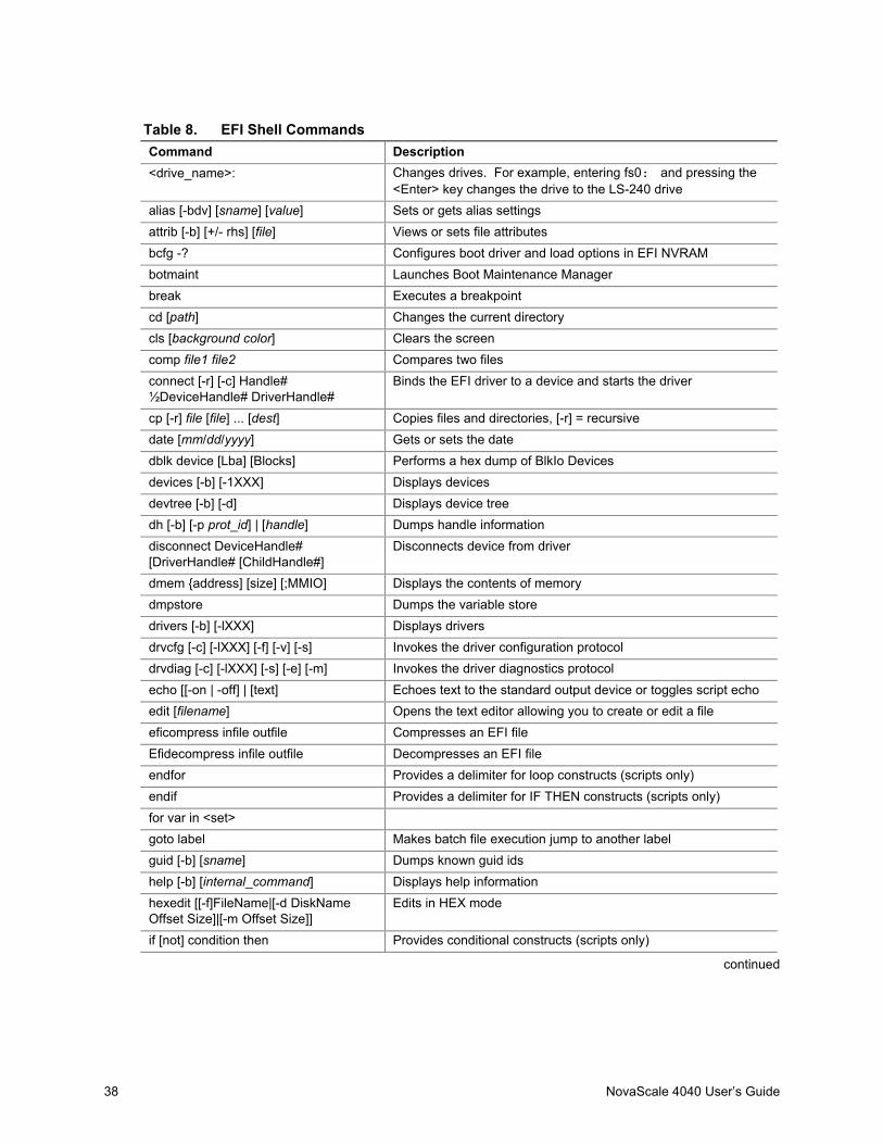
38 NovaScale 4040 User’s Guide
Table 8. EFI Shell CommandsCommand Description<drive_name>: Changes drives. For example, entering fs0: and pressing the
<Enter> key changes the drive to the LS-240 drivealias [-bdv] [sname] [value] Sets or gets alias settingsattrib [-b] [+/- rhs] [file] Views or sets file attributesbcfg -? Configures boot driver and load options in EFI NVRAMbotmaint Launches Boot Maintenance Managerbreak Executes a breakpointcd [path] Changes the current directorycls [background color] Clears the screencomp file1 file2 Compares two filesconnect [-r] [-c] Handle#½DeviceHandle# DriverHandle#
Binds the EFI driver to a device and starts the driver
cp [-r] file [file] ... [dest] Copies files and directories, [-r] = recursivedate [mm/dd/yyyy] Gets or sets the datedblk device [Lba] [Blocks] Performs a hex dump of BlkIo Devicesdevices [-b] [-1XXX] Displays devicesdevtree [-b] [-d] Displays device treedh [-b] [-p prot_id] | [handle] Dumps handle informationdisconnect DeviceHandle#[DriverHandle# [ChildHandle#]
Disconnects device from driver
dmem {address] [size] [;MMIO] Displays the contents of memorydmpstore Dumps the variable storedrivers [-b] [-lXXX] Displays driversdrvcfg [-c] [-lXXX] [-f] [-v] [-s] Invokes the driver configuration protocoldrvdiag [-c] [-lXXX] [-s] [-e] [-m] Invokes the driver diagnostics protocolecho [[-on | -off] | [text] Echoes text to the standard output device or toggles script echoedit [filename] Opens the text editor allowing you to create or edit a fileeficompress infile outfile Compresses an EFI fileEfidecompress infile outfile Decompresses an EFI fileendfor Provides a delimiter for loop constructs (scripts only)endif Provides a delimiter for IF THEN constructs (scripts only)for var in <set>goto label Makes batch file execution jump to another labelguid [-b] [sname] Dumps known guid idshelp [-b] [internal_command] Displays help informationhexedit [[-f]FileName|[-d DiskNameOffset Size]|[-m Offset Size]]
Edits in HEX mode
if [not] condition then Provides conditional constructs (scripts only)
continued

Configuration Software and Utilities 39
Table 8. EFI Shell Commands (continued)Command Descriptionload driver_name Loads a driverloadbmp [-c] [-t] [-i[UGA Instance]] file Displays a bitmap file on the screenloadpcirom romfile Loads a PCI option ROMls [-b] [dir] [dir] ... Obtains directory listingsmap [-bdvr] [sname[:]] [handle] Maps sname to device pathmem [address] [size] [;MMIO] Dumps Memory or Memory Mapped IOmemmap [-b] Dumps memory mapmkdir dir [dir] Creates a new directorymm address [Width] [;Type] [n] Memory Modify: type = Mem, MMIO, IO, PCI, [n] for non
interactive mode when inside a .nsh filemode [col row] Sets or gets the current graphics modemount BlkDevice [sname[:]] Mounts a file system on a block devicemv [src…] [dst] Move one or more files/directories to destinationpause Prompts to quit or continue (scripts only)pci [bus_dev] [func] Displays PCI device informationrconnect DeviceHandle#[DriverHandle# [ChildHandle#]] | [-r]
Reconnects one or more drivers from a device
reset [reset_string] Performs a cold resetrm file/dir [file/dir] Removes files or directoriessetsize file Sets size of a new filestall microseconds Delays for the specified number of microsecondstime [hh:mm:ss] Gets or sets the timetype [-a] [-u] [-b] file Displays the contents of a filever Displays version informationvol fs [volume_label] Sets or displays a volume label
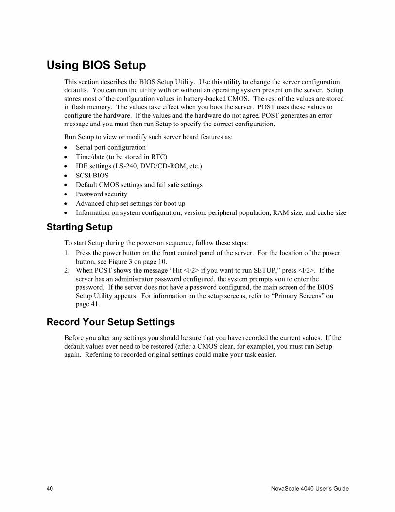
40 NovaScale 4040 User’s Guide
Using BIOS SetupThis section describes the BIOS Setup Utility. Use this utility to change the server configurationdefaults. You can run the utility with or without an operating system present on the server. Setupstores most of the configuration values in battery-backed CMOS. The rest of the values are storedin flash memory. The values take effect when you boot the server. POST uses these values toconfigure the hardware. If the values and the hardware do not agree, POST generates an errormessage and you must then run Setup to specify the correct configuration.
Run Setup to view or modify such server board features as:• Serial port configuration• Time/date (to be stored in RTC)• IDE settings (LS-240, DVD/CD-ROM, etc.)• SCSI BIOS• Default CMOS settings and fail safe settings• Password security• Advanced chip set settings for boot up• Information on system configuration, version, peripheral population, RAM size, and cache size
Starting SetupTo start Setup during the power-on sequence, follow these steps:1. Press the power button on the front control panel of the server. For the location of the power
button, see Figure 3 on page 10.2. When POST shows the message “Hit <F2> if you want to run SETUP,” press <F2>. If the
server has an administrator password configured, the system prompts you to enter thepassword. If the server does not have a password configured, the main screen of the BIOSSetup Utility appears. For information on the setup screens, refer to “Primary Screens” onpage 41.
Record Your Setup SettingsBefore you alter any settings you should be sure that you have recorded the current values. If thedefault values ever need to be restored (after a CMOS clear, for example), you must run Setupagain. Referring to recorded original settings could make your task easier.
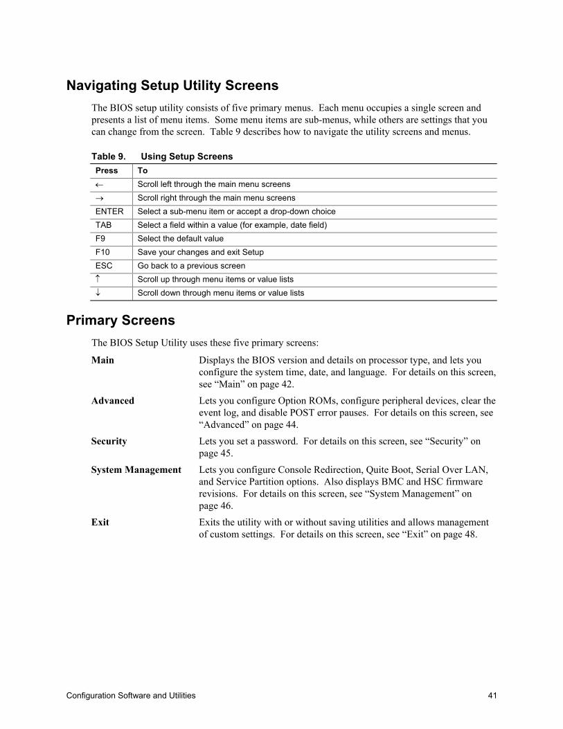
Configuration Software and Utilities 41
Navigating Setup Utility ScreensThe BIOS setup utility consists of five primary menus. Each menu occupies a single screen andpresents a list of menu items. Some menu items are sub-menus, while others are settings that youcan change from the screen. Table 9 describes how to navigate the utility screens and menus.
Table 9. Using Setup ScreensPress To← Scroll left through the main menu screens→ Scroll right through the main menu screensENTER Select a sub-menu item or accept a drop-down choiceTAB Select a field within a value (for example, date field)F9 Select the default valueF10 Save your changes and exit SetupESC Go back to a previous screen↑ Scroll up through menu items or value lists↓ Scroll down through menu items or value lists
Primary ScreensThe BIOS Setup Utility uses these five primary screens:
Main Displays the BIOS version and details on processor type, and lets youconfigure the system time, date, and language. For details on this screen,see “Main” on page 42.
Advanced Lets you configure Option ROMs, configure peripheral devices, clear theevent log, and disable POST error pauses. For details on this screen, see“Advanced” on page 44.
Security Lets you set a password. For details on this screen, see “Security” onpage 45.
System Management Lets you configure Console Redirection, Quite Boot, Serial Over LAN,and Service Partition options. Also displays BMC and HSC firmwarerevisions. For details on this screen, see “System Management” onpage 46.
Exit Exits the utility with or without saving utilities and allows managementof custom settings. For details on this screen, see “Exit” on page 48.
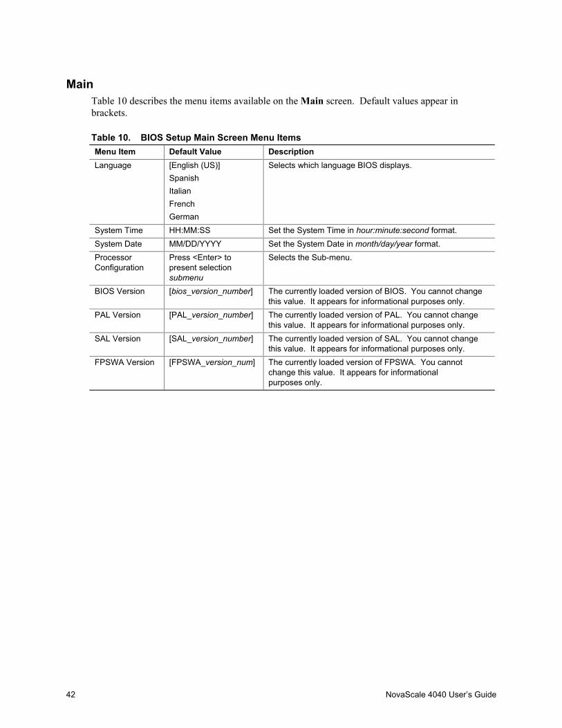
42 NovaScale 4040 User’s Guide
MainTable 10 describes the menu items available on the Main screen. Default values appear inbrackets.
Table 10. BIOS Setup Main Screen Menu ItemsMenu Item Default Value DescriptionLanguage [English (US)]
SpanishItalianFrenchGerman
Selects which language BIOS displays.
System Time HH:MM:SS Set the System Time in hour:minute:second format.System Date MM/DD/YYYY Set the System Date in month/day/year format.ProcessorConfiguration
Press <Enter> topresent selectionsubmenu
Selects the Sub-menu.
BIOS Version [bios_version_number] The currently loaded version of BIOS. You cannot changethis value. It appears for informational purposes only.
PAL Version [PAL_version_number] The currently loaded version of PAL. You cannot changethis value. It appears for informational purposes only.
SAL Version [SAL_version_number] The currently loaded version of SAL. You cannot changethis value. It appears for informational purposes only.
FPSWA Version [FPSWA_version_num] The currently loaded version of FPSWA. You cannotchange this value. It appears for informationalpurposes only.

Configuration Software and Utilities 43
Table 11. Processor Configuration Submenu ItemsMenu Item Default Value DescriptionProcessor Retest [No]
YesIf yes, BIOS clears historical processor statusand retests all processors on the next boot
Processor 1 CPUID N/A Reports CPUID for Processor 1Processor 1 L1 Cache Size N/A Reports L1 Cache Size for Processor 1Processor 1 L2 Cache Size N/A Reports L2 Cache Size for Processor 1Processor 1 L3 Cache Size N/A Reports L3 Cache Size for Processor 1Processor 2 CPUID N/A Reports CPUID of the Processor 2Processor 2 L1 Cache Size N/A Reports L1 Cache Size for Processor 2Processor 2 L2 Cache Size N/A Reports L2 Cache Size for Processor 2Processor 2 L3 Cache Size N/A Reports L3 Cache Size for Processor 2Processor 3 CPUID N/A Reports CPUID of the Processor 3Processor 3 L1 Cache Size N/A Reports L1 Cache Size for Processor 3Processor 3 L2 Cache Size N/A Reports L2 Cache Size for Processor 3Processor 3 L3 Cache Size N/A Reports L3 Cache Size for Processor 3Processor 4 CPUID N/A Reports CPUID for Processor 4Processor 4 L1 Cache Size N/A Reports L1 Cache Size for Processor 4Processor 4 L2 Cache Size N/A Reports L2 Cache Size for Processor 4Processor 4 L3 Cache Size N/A Reports L3 Cache Size for Processor 4
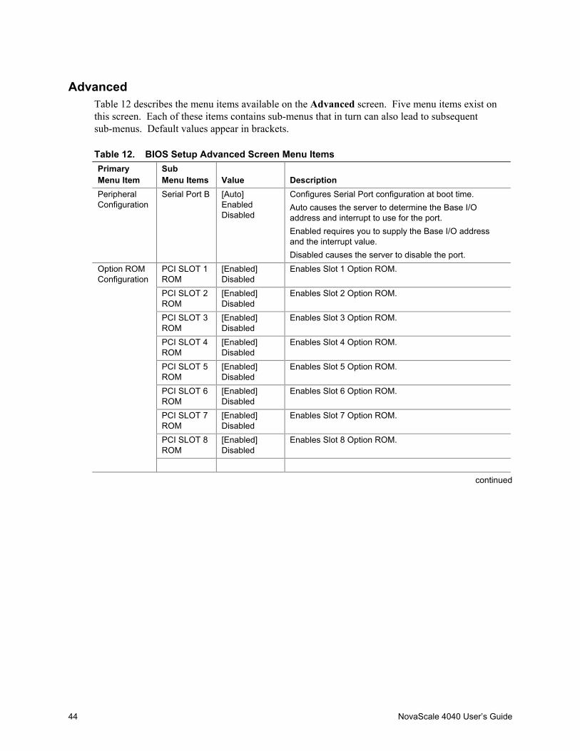
44 NovaScale 4040 User’s Guide
AdvancedTable 12 describes the menu items available on the Advanced screen. Five menu items exist onthis screen. Each of these items contains sub-menus that in turn can also lead to subsequentsub-menus. Default values appear in brackets.
Table 12. BIOS Setup Advanced Screen Menu ItemsPrimaryMenu Item
SubMenu Items Value Description
PeripheralConfiguration
Serial Port B [Auto]EnabledDisabled
Configures Serial Port configuration at boot time.Auto causes the server to determine the Base I/Oaddress and interrupt to use for the port.Enabled requires you to supply the Base I/O addressand the interrupt value.Disabled causes the server to disable the port.
PCI SLOT 1ROM
[Enabled]Disabled
Enables Slot 1 Option ROM.
PCI SLOT 2ROM
[Enabled]Disabled
Enables Slot 2 Option ROM.
PCI SLOT 3ROM
[Enabled]Disabled
Enables Slot 3 Option ROM.
PCI SLOT 4ROM
[Enabled]Disabled
Enables Slot 4 Option ROM.
PCI SLOT 5ROM
[Enabled]Disabled
Enables Slot 5 Option ROM.
PCI SLOT 6ROM
[Enabled]Disabled
Enables Slot 6 Option ROM.
PCI SLOT 7ROM
[Enabled]Disabled
Enables Slot 7 Option ROM.
PCI SLOT 8ROM
[Enabled]Disabled
Enables Slot 8 Option ROM.
Option ROMConfiguration
continued
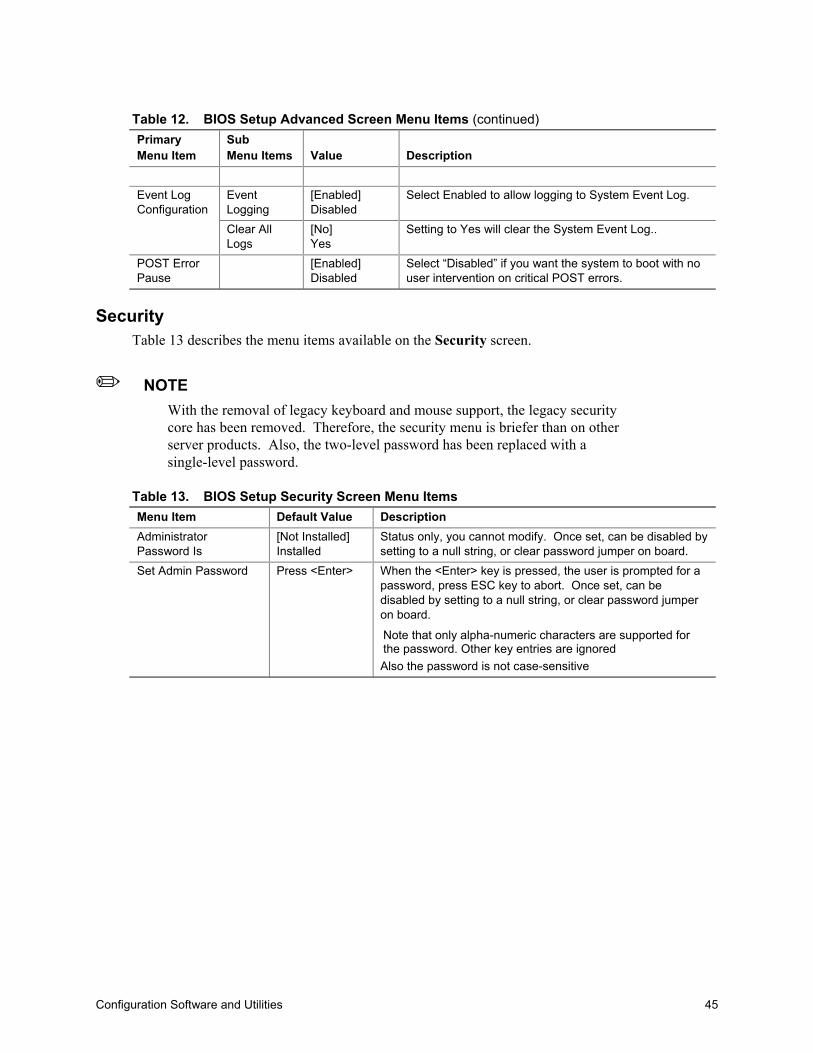
Configuration Software and Utilities 45
Table 12. BIOS Setup Advanced Screen Menu Items (continued)PrimaryMenu Item
SubMenu Items Value Description
EventLogging
[Enabled]Disabled
Select Enabled to allow logging to System Event Log.Event LogConfiguration
Clear AllLogs
[No]Yes
Setting to Yes will clear the System Event Log..
POST ErrorPause
[Enabled]Disabled
Select “Disabled” if you want the system to boot with nouser intervention on critical POST errors.
SecurityTable 13 describes the menu items available on the Security screen.
✏ NOTEWith the removal of legacy keyboard and mouse support, the legacy securitycore has been removed. Therefore, the security menu is briefer than on otherserver products. Also, the two-level password has been replaced with asingle-level password.
Table 13. BIOS Setup Security Screen Menu ItemsMenu Item Default Value DescriptionAdministratorPassword Is
[Not Installed]Installed
Status only, you cannot modify. Once set, can be disabled bysetting to a null string, or clear password jumper on board.
Set Admin Password Press <Enter> When the <Enter> key is pressed, the user is prompted for apassword, press ESC key to abort. Once set, can bedisabled by setting to a null string, or clear password jumperon board.
Note that only alpha-numeric characters are supported forthe password. Other key entries are ignoredAlso the password is not case-sensitive

46 NovaScale 4040 User’s Guide
System ManagementTable 14 describes the menu items available on the System Management screen. Default valuesappear in brackets.
Table 14. BIOS Setup System Management Screen Menu ItemsMenu Item Default Value DescriptionQuiet Boot [Enabled]
DisabledSelecting this option enables the BIOS to display the OEMlogo during POST. If disabled, the BIOS displays the normalPOST messages.This option is hidden if the BIOS does not detect a valid logoin the flash area reserved for this purpose.Enabling this option disables serial redirection.
Service Boot [Disabled]Enabled
Enabling this item allows you to boot into Service PartitionBoot mode. The item automatically resets to “Disabled” onthe next system boot.
>Console Redirection Press <Enter>to presentselectionsubmenu
Selecting this option allows you to configure for consoleredirection.
Platform Event Filtering [Enabled]Disabled
Enabling this item authorizes filtering of events in the SMU.
OS Boot Timeout [Enabled]Disabled5 minutes10 minutes15 minutes20 minutes
Sets the time allowed for booting an OS, from media or PXE.
BMC Revision [BMC_Rev] The currently loaded version of Baseboard ManagementController firmware. You cannot change this value. Itappears for informational purposes only.
HSC Revision [HSC_Rev] Information field only, hidden if not detected. Displays the HotSwap Controller revision.
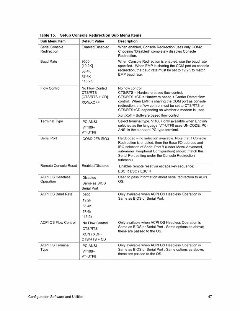
Configuration Software and Utilities 47
Table 15. Setup Console Redirection Sub Menu ItemsSub Menu Item Default Value DescriptionSerial ConsoleRedirection
Enabled/Disabled When enabled, Console Redirection uses only COM2.Choosing “Disabled” completely disables ConsoleRedirection.
Baud Rate 9600[19.2K]38.4K57.6K115.2K
When Console Redirection is enabled, use the baud ratespecified. When EMP is sharing the COM port as consoleredirection, the baud rate must be set to 19.2K to matchEMP baud rate.
Flow Control No Flow ControlCTS/RTS[CTS/RTS + CD]XON/XOFF
No flow control.CTS/RTS = Hardware based flow control.CTS/RTS +CD = Hardware based + Carrier Detect flowcontrol. When EMP is sharing the COM port as consoleredirection, the flow control must be set to CTS/RTS orCTS/RTS+CD depending on whether a modem is used.Xon/Xoff = Software based flow control
Terminal Type PC-ANSIVT100+VT-UTF8
Select terminal type. Vt100+ only available when Englishselected as the language. VT-UTF8 uses UNICODE. PC-ANSI is the standard PC-type terminal.
Serial Port COM2 2F8 IRQ3 Hardcoded – no selection available. Note that if ConsoleRedirection is enabled, then the Base I/O address andIRQ selection of Serial Port B (under Menu Advanced,sub-menu Peripheral Configuration) should match thisSerial Port setting under the Console Redirectionsubmenu.
Remote Console Reset Enabled/Disabled Enables remote reset via escape key sequence;ESC R ESC r ESC R
ACPI OS HeadlessOperation
DisabledSame as BIOSSerial Port
Used to pass information about serial redirection to ACPIOS.
ACPI OS Baud Rate 960019.2k38.4K57.6k115.2k
Only available when ACPI OS Headless Operation isSame as BIOS or Serial Port.
ACPI OS Flow Control No Flow ControlCTS/RTSXON / XOFFCTS/RTS + CD
Only available when ACPI OS Headless Operation isSame as BIOS or Serial Port . Same options as above;these are passed to the OS.
ACPI OS TerminalType
PC-ANSIVT100+VT-UTF8
Only available when ACPI OS Headless Operation isSame as BIOS or Serial Port . Same options as above;these are passed to the OS.

48 NovaScale 4040 User’s Guide
ExitTable 16 describes the menu items available on the Exit screen. Default values appear in brackets.
Table 16. BIOS Setup Exit Screen Menu ItemsMenu Item DescriptionExit Saving Changes Lets you exit Setup with or without saving your changes in CMOS. Clicking on
the menu item causes the system to prompt you for a Yes or No response.Yes Saves your changes and exits the utility.No Discards your changes and exits the utility.
Exit Discarding Changes Lets you exit Setup with or without discarding your changes. Clicking on themenu item causes the system to prompt you for a Yes or No response.Yes Discards your changes and exits the utility.No Saves your changes and exits the utility.
Load Setup Defaults Lets you load Setup with factory defaults. Clicking on the menu item causes thesystem to prompt you for a Yes or No response.Yes Loads the system setup defaults.No Aborts the action.
Save Custom Defaults Lets you load Setup with custom defaults. Clicking on the menu item causesthe system to prompt you for a Yes or No response.Yes Loads setup values from a file previously saved through the Save
Custom Defaults menu item. You must specify the file name.No Aborts the action.
Discard Changes Lets you discard the changed values you have accumulated during this setupsession. Clicking on the menu item causes the system to prompt you for a Yesor No response.Yes Discards the setup values for the current setup utility session.No Aborts the action.

Configuration Software and Utilities 49
LSI SCSI UtilityThe LSI SCSI utility allows you to configure the SCSI capabilities of the server. Please contactyour Bull representative for more information on how obtaining this utility.
The EFI utility can be evoked from the EFI shell prompt with the command EFICnfg.efi. Fromhere the SCSI drives can be configured. The utility contains help information at the bottom of eachscreen. More information on this utility will be documented in a future revision of this document.
✏ NOTEThis utility is still being defined and changes may occur in the menus shownbelow. Entrance into this utility may be updated in a future revision of thisdocument.
To run the LSI SCSI utility:1. From the EFI Shell, run EFICnfg.efi to enter the LSI Logic SCSI Utility. The following
information is displayed on your monitor:EFI Configuration Utility Ver 1.0 Build 3
1. OnBoard Function0 Usb Universal Host Controller
2. OnBoard Function1 Usb Universal Host Controller
3. OnBoard Function0 LSI Logic Ultra320 SCSI Controller
4. OnBoard Function1 LSI Logic Ultra320 SCSI Controller
Please enter a serial number (Enter 0 to Exit):
2. Select the Function0 LSI Logic Ultra320 SCSI Controller’s serial number (in this case, 3) andpress <Enter>.
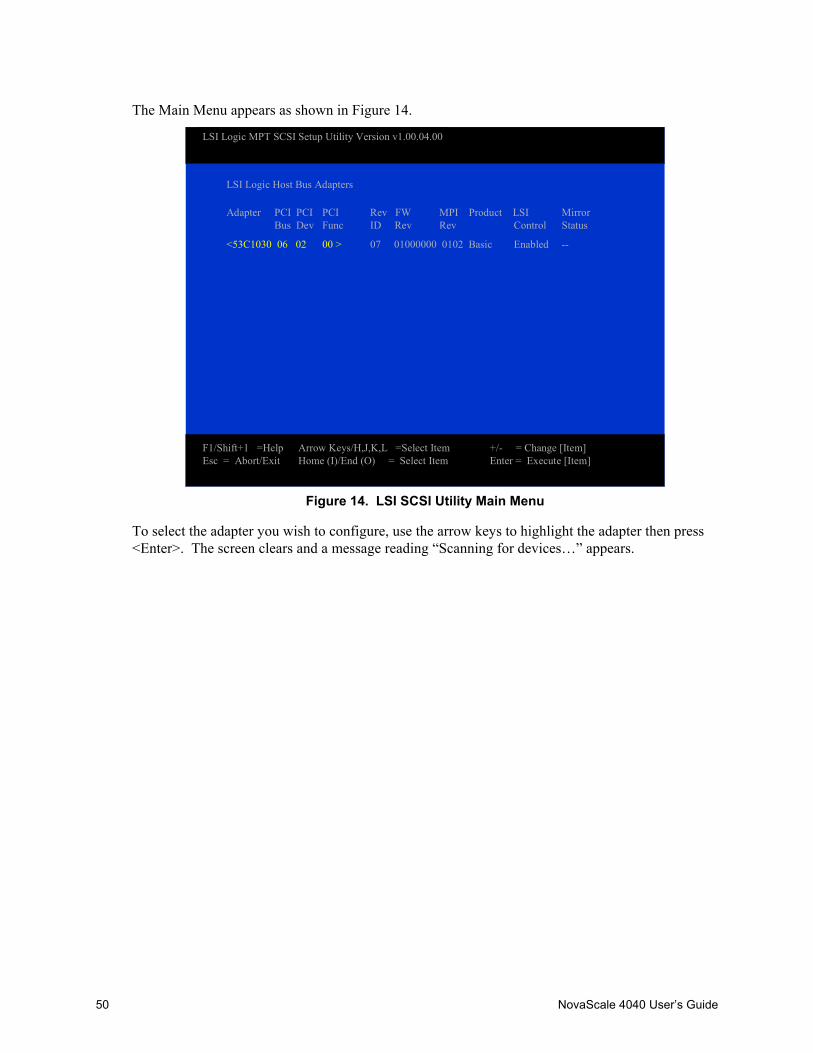
50 NovaScale 4040 User’s Guide
The Main Menu appears as shown in Figure 14.
LSI Logic MPT SCSI Setup Utility Version v1.00.04.00
LSI Logic Host Bus Adapters
Adapter PCI PCI PCI Rev FW MPI Product LSI MirrorBus Dev Func ID Rev Rev Control Status
<53C1030 06 02 00 > 07 01000000 0102 Basic Enabled --
F1/Shift+1 =Help Arrow Keys/H,J,K,L =Select Item +/- = Change [Item]Esc = Abort/Exit Home (I)/End (O) = Select Item Enter = Execute [Item]
Figure 14. LSI SCSI Utility Main Menu
To select the adapter you wish to configure, use the arrow keys to highlight the adapter then press<Enter>. The screen clears and a message reading “Scanning for devices…” appears.
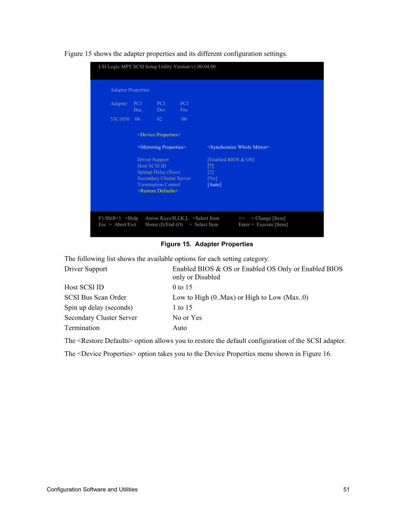
Configuration Software and Utilities 51
Figure 15 shows the adapter properties and its different configuration settings.
Adapter Properties
Adapter PCI PCI PCIBus Dev Fnc
53C1030 06 02 00
<Device Properties>
<Mirroring Properties> <Synchronize Whole Mirror>
Driver Support [Enabled BIOS & OS]Host SCSI ID [7]Spinup Delay (Secs) [2]Secondary Cluster Server [No]Termination Control [Auto]<Restore Defaults>
F1/Shift+1 =Help Arrow Keys/H,J,K,L =Select Item +/- = Change [Item]Esc = Abort/Exit Home (I)/End (O) = Select Item Enter = Execute [Item]
LSI Logic MPT SCSI Setup Utility Version v1.00.04.00
Figure 15. Adapter Properties
The following list shows the available options for each setting category.Driver Support Enabled BIOS & OS or Enabled OS Only or Enabled BIOS
only or DisabledHost SCSI ID 0 to 15SCSI Bus Scan Order Low to High (0..Max) or High to Low (Max..0)Spin up delay (seconds) 1 to 15Secondary Cluster Server No or YesTermination Auto
The <Restore Defaults> option allows you to restore the default configuration of the SCSI adapter.
The <Device Properties> option takes you to the Device Properties menu shown in Figure 16.

52 NovaScale 4040 User’s Guide
Device Properties
SCSI Device Identifier MB/ MT/ Data Scan Scan Luns Disconnect SCSI QueueID Sec Sec Width ID >0 Timeout Tags
01~6 ESG-SHV7 53C1030
12 Maxtor 320 [160] [16] [Yes] [Yes] [On] <10> [On]
8~11
131415 Format Verify Restore Defaults
<Format> <Verify> <Defaults>
F1/Shift+1 =Help Arrow Keys/H,J,K,L =Select Item +/- = Change [Item]Esc = Abort/Exit Home (I)/End (O) = Select Item Enter = Execute [Item]
LSI Logic MPT SCSI Setup Utility Version v1.00.04.00
Figure 16. Device Properties
The Device Properties Menu shows options of devices attached to the adapter. It is a large menuand requires the use of the arrow keys to move fully to the left and fully down to see allconfiguration options. There are “slide bars” (not shown above) to the right and on the bottom tohelp define your location in the menu. The following list shows the available options for eachsetting category:MB/Sec 320MT/Sec 0 or 5, 10, 20, 40, 80, 160Data Width 16 or 8Scan ID Yes or NoScan Luns >0 Yes or NoDisconnect On or OffSCSI Timeout <10>Queue Tags On or Off
Format, Verify, and Restore Defaults are all functions. They are located on the far left of the menu,but are shown below the other configuration options in the figure above. Format and Verify takesyou to another menu, see Figure 17 and Figure 18 below. These menus give appropriate warningsand allow you the option of continuing with the function or canceling. Restore Defaults functiondoes not take you another menu and does not give you the option to cancel. If you make changesand then accidentally select the Restore Defaults function, all changes will be discarded.
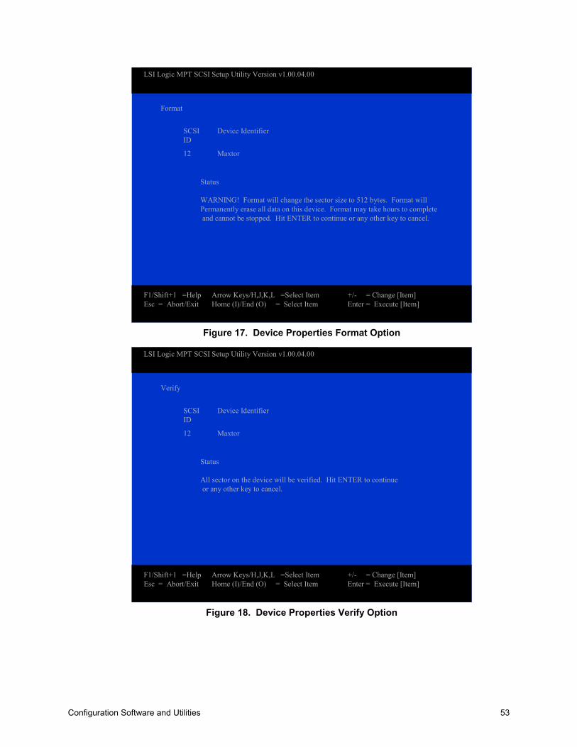
Configuration Software and Utilities 53
Format
SCSI Device IdentifierID
12 Maxtor
Status
WARNING! Format will change the sector size to 512 bytes. Format willPermanently erase all data on this device. Format may take hours to completeand cannot be stopped. Hit ENTER to continue or any other key to cancel.
F1/Shift+1 =Help Arrow Keys/H,J,K,L =Select Item +/- = Change [Item]Esc = Abort/Exit Home (I)/End (O) = Select Item Enter = Execute [Item]
LSI Logic MPT SCSI Setup Utility Version v1.00.04.00
Figure 17. Device Properties Format Option
Verify
SCSI Device IdentifierID
12 Maxtor
Status
All sector on the device will be verified. Hit ENTER to continueor any other key to cancel.
F1/Shift+1 =Help Arrow Keys/H,J,K,L =Select Item +/- = Change [Item]Esc = Abort/Exit Home (I)/End (O) = Select Item Enter = Execute [Item]
LSI Logic MPT SCSI Setup Utility Version v1.00.04.00
Figure 18. Device Properties Verify Option

54 NovaScale 4040 User’s Guide
Adapter and/or device property changes have been made.
<Cancel Exit>
<Save chance then exit this menu>
<Discard Changes then exit this menu>
Exit the configuration utility
F1/Shift+1 =Help Arrow Keys/H,J,K,L =Select Item +/- = Change [Item]Esc = Abort/Exit Home (I)/End (O) = Select Item Enter = Execute [Item]
LSI Logic MPT SCSI Setup Utility Version v1.00.04.00
Figure 19. Adapter and/or Device Properties Exit Menu
When exiting the Adapter Properties Menu, if any changes have been made, the Exit Menu appearsgiving the following three options. Cancel Exit, Save Changes then exit, or Discard changesand exit.
Are you sure you want to exit?
<Cancel Exit>
Save chance then exit this menu
Discard Changes then exit this menu
<Exit the configuration utility>
F1/Shift+1 =Help Arrow Keys/H,J,K,L =Select Item +/- = Change [Item]Esc = Abort/Exit Home (I)/End (O) = Select Item Enter = Execute [Item]
LSI Logic MPT SCSI Setup Utility Version v1.00.04.00
Figure 20. SCSI Utility Exit Menu

Configuration Software and Utilities 55
When exiting the LSI Logic MPT SCSI Setup Utility, if any changes have been made, the ExitMenu appears giving you these options. Cancel Exit, Save Changes then exit, or Discard changesand exit. The above menu shows the exit menu that appears if no changes have been made to theSetup Utility.
After exiting, you are returned to the EFI Shell prompt.

56 NovaScale 4040 User’s Guide
The NovaScale 4040 Resource CDThe NovaScale 4040 Resource CD has the following contents:• LSI Logic SCSI Driver for Linux† (64-bit) and Windows† .NET• Utilities:
System Maintenance Utility (SMU) EFI Platform Diagnostics EFI Configuration Tool Save and Restore Configuration Utility Ramdriver
• Service Partition Files• The NovaScale 4040 Documentation• Adobe Acrobat Reader
The Resource CD comes with a menu driven program that can be used for the following:• Create removable media containing utilities.• Install EFI Service Partition. The EFI service partition provides the ability to remotely access
NovaScale 4040 via modem or LAN for the purpose of executing configuration/setup utilitiesand diagnostics.
• Run NovaScale 4040 EFI based utilities.
Running Software Utilities Directly from the Resource CDThe following procedure allows you to run the software utilities directly from the NovaScale 4040Resource CD.1. Insert the System Resource CD into the server’s CD-ROM drive before booting to EFI Shell.2. Boot the system into EFI Shell, the EFI CD Menu program launches automatically. If the EFI
CD Menu program does not launch in the EFI Shell, mount and map to the CD drive and type‘startup’ and press <Enter> to launch the EFI CD Menu.
3. Move the curser over to the Utilities and select the utility you want to run.

Configuration Software and Utilities 57
System Maintenance UtilityThe System Maintenance Utility is an EFI-based program that provides the ability to view ormodify the server management firmware configuration, which is maintained by the BMC. Theexecutable program for the SMU is smu.efi.
The SMU lets the user:• Configure serial/modem channels for remote server management over a modem or direct serial
connection.• Configure LAN channels for remote server management over the network.• Configure users and associated passwords for channel access. Users and channels can be
assigned privilege levels to further define the access levels.• Configure platform events to define the actions that should take place when specific events
occur.• Configure serial over LAN and terminal mode capabilities.• Configure the power restore policy for the server.• View, save and clear the BMC System Event Log.• View and save the BMC Sensor Data Records.• View and save the Field Replaceable Unit records.
The SMU core components are installed as part of the service partition software installation processand the remote SMU application is part of the Intel® Server Management installation. SMU files arecopied to a directory specified during that installation process. It is also possible to run the localSMU application from a CD without installing a service partition.
The SMU software consists of a user interface and core components. The user interfacecomponents present the user interface, gather user input, and send input to the core components.The core components interpret data and perform necessary actions to the hardware. The corecomponents also maintain the state of the application and determine the screens to be shown.Specific state information is stored in the data that is exchanged between the user interface and corecomponents.
The core components of the SMU are the same for the local and remote applications. If the SMU isrun locally, the user interface component will be an EFI application that uses the PortableEmbedded GUI (PEG) graphics library to present the user interface. When running remotely, theuser interface component will be a Java application. Running the remote SMU requires the use ofIntel Server Management.
✏ NOTEThe local SMU application is available only in English.
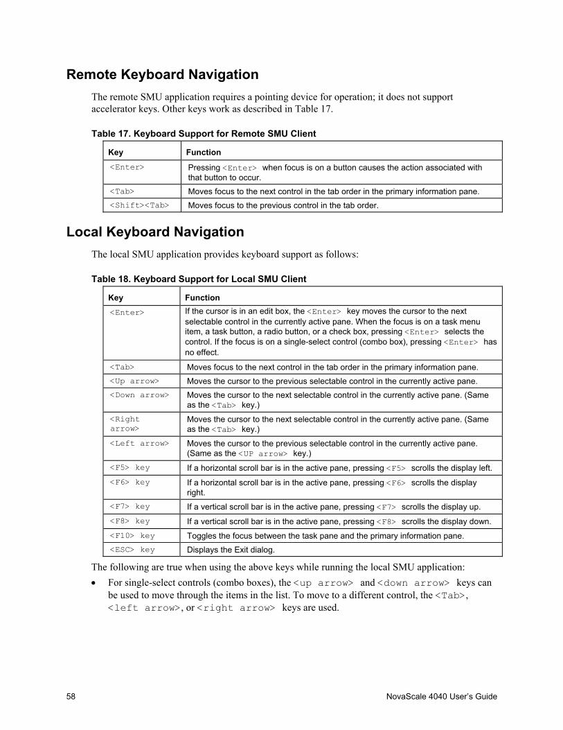
58 NovaScale 4040 User’s Guide
Remote Keyboard NavigationThe remote SMU application requires a pointing device for operation; it does not supportaccelerator keys. Other keys work as described in Table 17.
Table 17. Keyboard Support for Remote SMU Client
Key Function<Enter> Pressing <Enter> when focus is on a button causes the action associated with
that button to occur.<Tab> Moves focus to the next control in the tab order in the primary information pane.<Shift><Tab> Moves focus to the previous control in the tab order.
Local Keyboard NavigationThe local SMU application provides keyboard support as follows:
Table 18. Keyboard Support for Local SMU Client
Key Function<Enter> If the cursor is in an edit box, the <Enter> key moves the cursor to the next
selectable control in the currently active pane. When the focus is on a task menuitem, a task button, a radio button, or a check box, pressing <Enter> selects thecontrol. If the focus is on a single-select control (combo box), pressing <Enter> hasno effect.
<Tab> Moves focus to the next control in the tab order in the primary information pane.<Up arrow> Moves the cursor to the previous selectable control in the currently active pane.<Down arrow> Moves the cursor to the next selectable control in the currently active pane. (Same
as the <Tab> key.)<Rightarrow>
Moves the cursor to the next selectable control in the currently active pane. (Sameas the <Tab> key.)
<Left arrow> Moves the cursor to the previous selectable control in the currently active pane.(Same as the <UP arrow> key.)
<F5> key If a horizontal scroll bar is in the active pane, pressing <F5> scrolls the display left.<F6> key If a horizontal scroll bar is in the active pane, pressing <F6> scrolls the display
right.<F7> key If a vertical scroll bar is in the active pane, pressing <F7> scrolls the display up.<F8> key If a vertical scroll bar is in the active pane, pressing <F8> scrolls the display down.<F10> key Toggles the focus between the task pane and the primary information pane.<ESC> key Displays the Exit dialog.
The following are true when using the above keys while running the local SMU application:• For single-select controls (combo boxes), the <up arrow> and <down arrow> keys can
be used to move through the items in the list. To move to a different control, the <Tab>,<left arrow>, or <right arrow> keys are used.
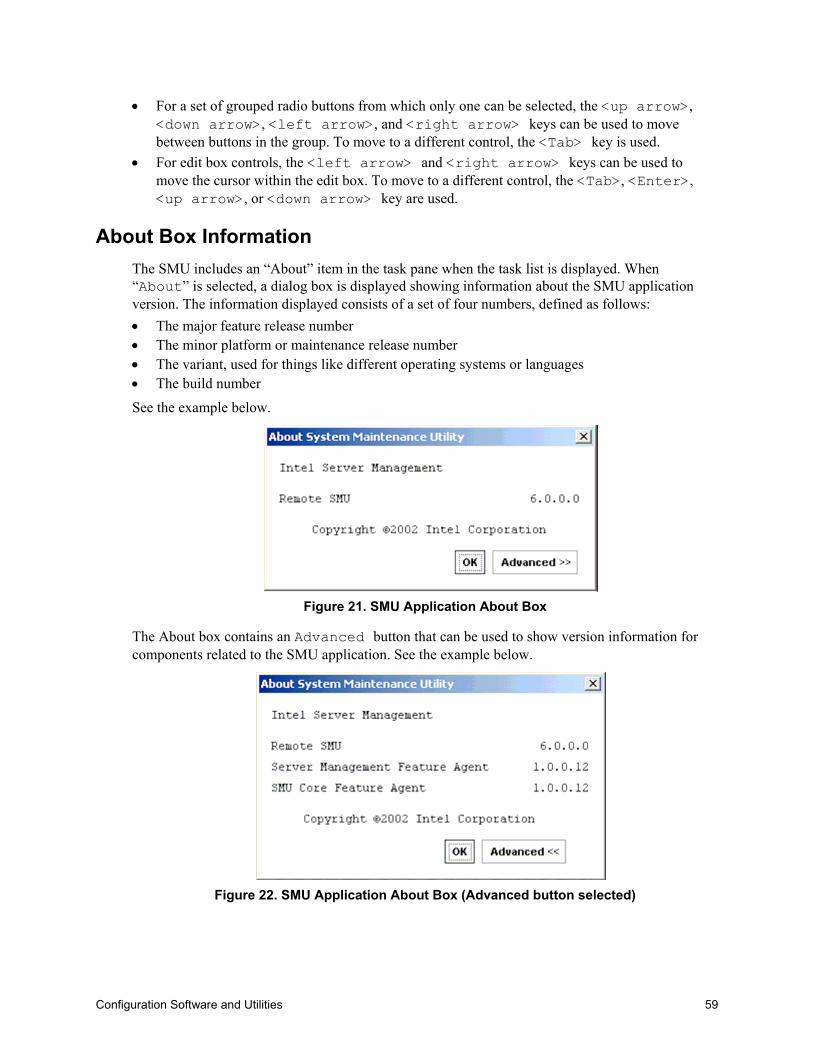
Configuration Software and Utilities 59
• For a set of grouped radio buttons from which only one can be selected, the <up arrow>,<down arrow>, <left arrow>, and <right arrow> keys can be used to movebetween buttons in the group. To move to a different control, the <Tab> key is used.
• For edit box controls, the <left arrow> and <right arrow> keys can be used tomove the cursor within the edit box. To move to a different control, the <Tab>, <Enter>,<up arrow>, or <down arrow> key are used.
About Box InformationThe SMU includes an “About” item in the task pane when the task list is displayed. When“About” is selected, a dialog box is displayed showing information about the SMU applicationversion. The information displayed consists of a set of four numbers, defined as follows:• The major feature release number• The minor platform or maintenance release number• The variant, used for things like different operating systems or languages• The build number
See the example below.
Figure 21. SMU Application About Box
The About box contains an Advanced button that can be used to show version information forcomponents related to the SMU application. See the example below.
Figure 22. SMU Application About Box (Advanced button selected)
60 NovaScale 4040 User’s Guide
Server DiscoveryThe remote SMU application requires that the Intel Server Management software be installed on theclient system. When the ISM software is run, it performs a discovery of all servers that supporttools available within ISM. The discovered servers are displayed in the ISM Console. By clickingon a server name in the table, a list of tools supported on that server is displayed. The SMU iscontained in the set of tools listed under the heading “Reboot to Service Partition”.
Remote SMU ApplicationThe path used to connect to a target server is defined by the ISM software, based on information ithas about each server. After a LAN connection is established between the remote SMU applicationand SMU core components on the server, the application and the core components set up a socketconnection to communicate through.
The sequence of steps that occur when starting the remote SMU application is listed below. Thesesteps occur under the control of the ISM software, not the SMU software, and all errors are handledby the ISM software.
1. In the ISM Console software, click on Reboot to Service Partition under the listof tools for a server shown.
2. Enter the username and password for an out-of-band connection on the Service PartitionUtilities screen.
3. Click Login.
4. When the server has been successfully rebooted to the service partition software, thesupported service partition utilities are displayed, as shown below. Click on SystemMaintenance Utility to launch the SMU application. ISM passes connectioninformation to the SMU so the SMU can communicate with the target server. Up to thispoint, all errors are handled by the ISM software, not the SMU.
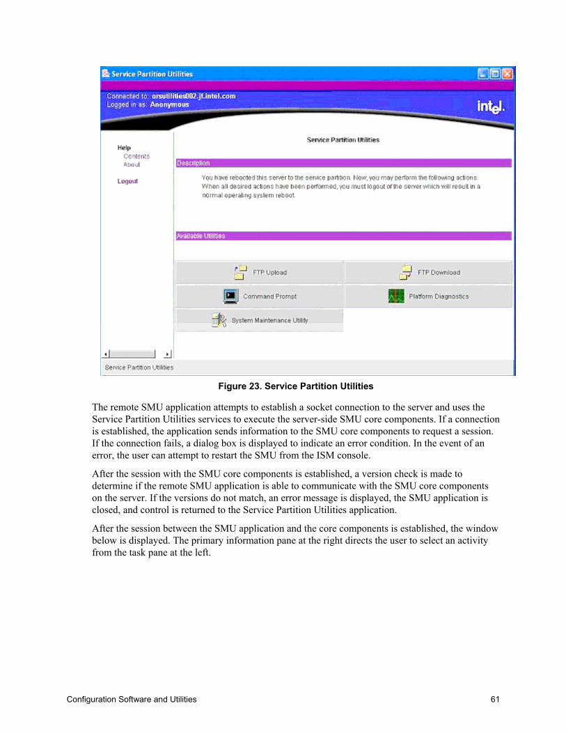
Configuration Software and Utilities 61
Figure 23. Service Partition Utilities
The remote SMU application attempts to establish a socket connection to the server and uses theService Partition Utilities services to execute the server-side SMU core components. If a connectionis established, the application sends information to the SMU core components to request a session.If the connection fails, a dialog box is displayed to indicate an error condition. In the event of anerror, the user can attempt to restart the SMU from the ISM console.
After the session with the SMU core components is established, a version check is made todetermine if the remote SMU application is able to communicate with the SMU core componentson the server. If the versions do not match, an error message is displayed, the SMU application isclosed, and control is returned to the Service Partition Utilities application.
After the session between the SMU application and the core components is established, the windowbelow is displayed. The primary information pane at the right directs the user to select an activityfrom the task pane at the left.
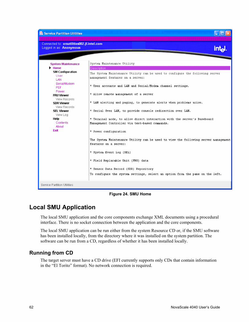
62 NovaScale 4040 User’s Guide
Figure 24. SMU Home
Local SMU ApplicationThe local SMU application and the core components exchange XML documents using a proceduralinterface. There is no socket connection between the application and the core components.
The local SMU application can be run either from the system Resource CD or, if the SMU softwarehas been installed locally, from the directory where it was installed on the system partition. Thesoftware can be run from a CD, regardless of whether it has been installed locally.
Running from CDThe target server must have a CD drive (EFI currently supports only CDs that contain informationin the “El Torito” format). No network connection is required.
Configuration Software and Utilities 63
The following sequence of steps is followed to start the SMU locally (assuming the systemResource CD is being used):
Insert the system Resource CD into the CD drive on the target server and boot the server to the EFIshell. The Resource CD menu program begins running automatically and displays a splashscreen followed by the main menu.
5. Use the arrow keys to move to the Utilities menu item. Press the <Enter> key.
6. Use the down arrow key to highlight the System Maintenance Utility menu item. Press the<Enter> key to start the local SMU application.
Running from the System PartitionTo run the SMU application from a service partition on which it has been installed, follow the stepsbelow:
If an EFI shell prompt is available on the local console and the files on the system partition can beaccessed, skip to step three.
7. Reset the server and boot to the EFI shell.
8. Locate the file system (e.g. fs0:, fs1:) that contains the service partition software and changedirectory to \efi\service\smu.
9. 4. Run smu.efi.
Shutdown SMU ApplicationExit either the local or remote SMU application by clicking on the Exit item in the task pane orby clicking the Close button in the upper right hand corner of the container. A user can also usethe Close option in the system menu of either container. An exit operation can be started at anytime (unless the application is blocked while it waits for a response from the server). During theexit process, the following steps occur:
The application sends a message to the SMU core components asking to end the SMU session.
10. The SMU core components send a message to the application asking for user confirmation ofthe exit request. This message is displayed as a dialog box with an OK button and a Cancelbutton.
11. Clicking the OK button causes the SMU application to send another message to the server toconfirm the exit request. If Cancel is clicked, the request to close is canceled.
12. A final message is sent to the application from the server before the application shuts down.When the local SMU application is used, it exits to the EFI shell. When the remote SMUapplication is used, control is returned to the Service Partition Utilities application.
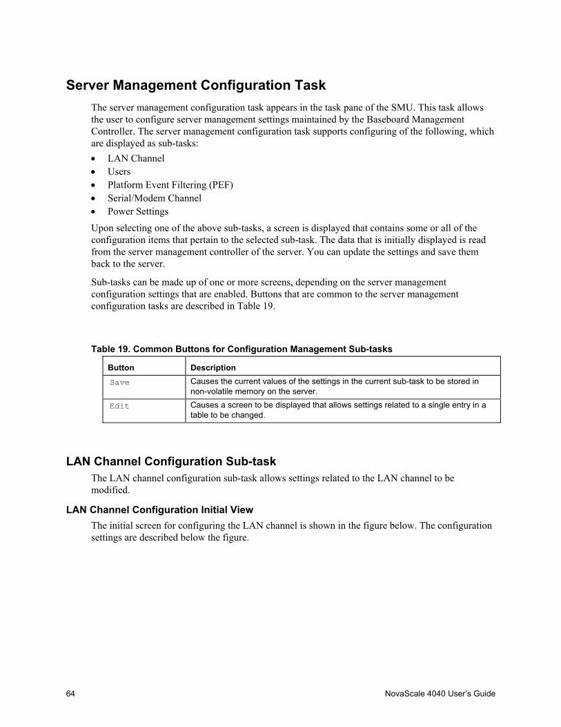
64 NovaScale 4040 User’s Guide
Server Management Configuration TaskThe server management configuration task appears in the task pane of the SMU. This task allowsthe user to configure server management settings maintained by the Baseboard ManagementController. The server management configuration task supports configuring of the following, whichare displayed as sub-tasks:• LAN Channel• Users• Platform Event Filtering (PEF)• Serial/Modem Channel• Power Settings
Upon selecting one of the above sub-tasks, a screen is displayed that contains some or all of theconfiguration items that pertain to the selected sub-task. The data that is initially displayed is readfrom the server management controller of the server. You can update the settings and save themback to the server.
Sub-tasks can be made up of one or more screens, depending on the server managementconfiguration settings that are enabled. Buttons that are common to the server managementconfiguration tasks are described in Table 19.
Table 19. Common Buttons for Configuration Management Sub-tasks
Button DescriptionSave Causes the current values of the settings in the current sub-task to be stored in
non-volatile memory on the server.
Edit Causes a screen to be displayed that allows settings related to a single entry in atable to be changed.
LAN Channel Configuration Sub-taskThe LAN channel configuration sub-task allows settings related to the LAN channel to bemodified.
LAN Channel Configuration Initial ViewThe initial screen for configuring the LAN channel is shown in the figure below. The configurationsettings are described below the figure.
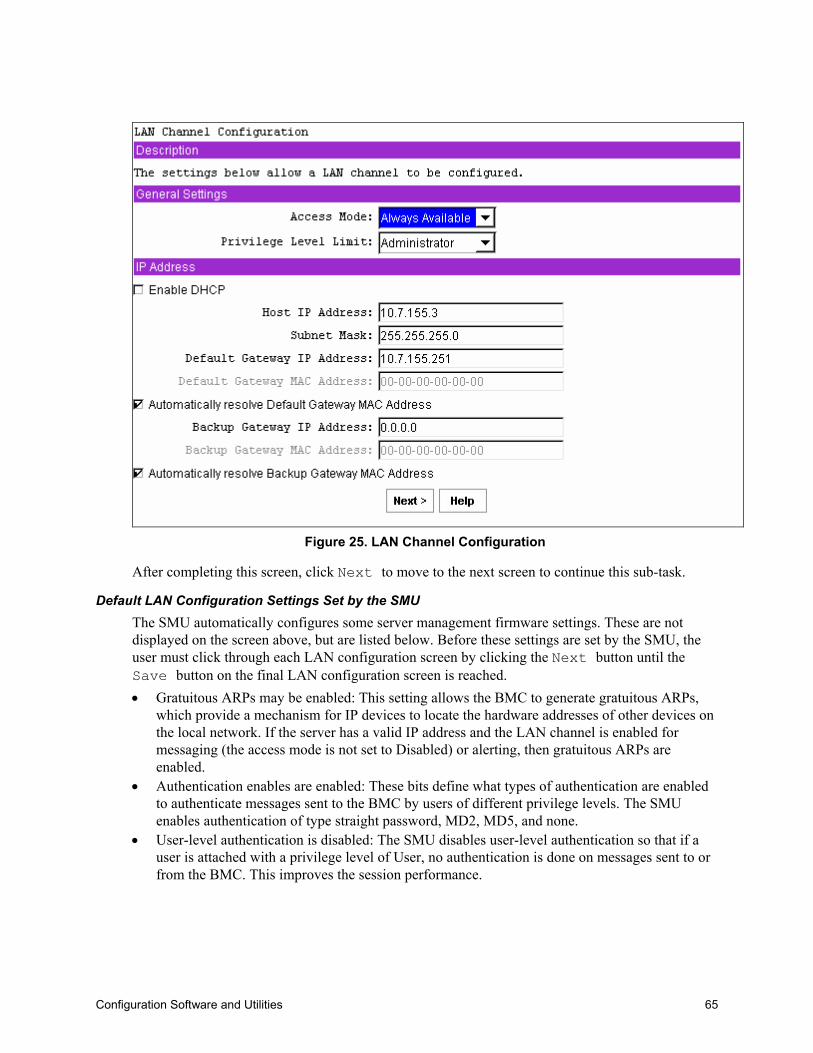
Configuration Software and Utilities 65
Figure 25. LAN Channel Configuration
After completing this screen, click Next to move to the next screen to continue this sub-task.
Default LAN Configuration Settings Set by the SMUThe SMU automatically configures some server management firmware settings. These are notdisplayed on the screen above, but are listed below. Before these settings are set by the SMU, theuser must click through each LAN configuration screen by clicking the Next button until theSave button on the final LAN configuration screen is reached.• Gratuitous ARPs may be enabled: This setting allows the BMC to generate gratuitous ARPs,
which provide a mechanism for IP devices to locate the hardware addresses of other devices onthe local network. If the server has a valid IP address and the LAN channel is enabled formessaging (the access mode is not set to Disabled) or alerting, then gratuitous ARPs areenabled.
• Authentication enables are enabled: These bits define what types of authentication are enabledto authenticate messages sent to the BMC by users of different privilege levels. The SMUenables authentication of type straight password, MD2, MD5, and none.
• User-level authentication is disabled: The SMU disables user-level authentication so that if auser is attached with a privilege level of User, no authentication is done on messages sent to orfrom the BMC. This improves the session performance.
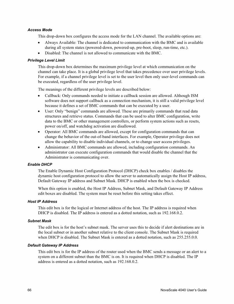
66 NovaScale 4040 User’s Guide
Access ModeThis drop-down box configures the access mode for the LAN channel. The available options are:• Always Available: The channel is dedicated to communication with the BMC and is available
during all system states (powered-down, powered-up, pre-boot, sleep, run-time, etc.).• Disabled: The channel is not allowed to communicate with the BMC.
Privilege Level LimitThis drop-down box determines the maximum privilege level at which communication on thechannel can take place. It is a global privilege level that takes precedence over user privilege levels.For example, if a channel privilege level is set to the user level then only user-level commands canbe executed, regardless of the user privilege level.
The meanings of the different privilege levels are described below:• Callback: Only commands needed to initiate a callback session are allowed. Although ISM
software does not support callback as a connection mechanism, it is still a valid privilege levelbecause it defines a set of BMC commands that can be executed by a user.
• User: Only “benign” commands are allowed. These are primarily commands that read datastructures and retrieve status. Commands that can be used to alter BMC configuration, writedata to the BMC or other management controllers, or perform system actions such as resets,power on/off, and watchdog activation are disallowed.
• Operator: All BMC commands are allowed, except for configuration commands that canchange the behavior of the out-of-band interfaces. For example, Operator privilege does notallow the capability to disable individual channels, or to change user access privileges.
• Administrator: All BMC commands are allowed, including configuration commands. Anadministrator can execute configuration commands that would disable the channel that theAdministrator is communicating over.
Enable DHCPThe Enable Dynamic Host Configuration Protocol (DHCP) check box enables / disables thedynamic host configuration protocol to allow the server to automatically assign the Host IP address,Default Gateway IP address and Subnet Mask. DHCP is enabled when the box is checked.
When this option is enabled, the Host IP Address, Subnet Mask, and Default Gateway IP Addressedit boxes are disabled. The system must be reset before this setting takes effect.
Host IP AddressThis edit box is for the logical or Internet address of the host. The IP address is required whenDHCP is disabled. The IP address is entered as a dotted notation, such as 192.168.0.2.
Subnet MaskThe edit box is for the host’s subnet mask. The server uses this to decide if alert destinations are inthe local subnet or in another subnet relative to the client console. The Subnet Mask is requiredwhen DHCP is disabled. The Subnet Mask is entered as a dotted notation, such as 255.255.0.0.
Default Gateway IP AddressThis edit box is for the IP address of the router used when the BMC sends a message or an alert to asystem on a different subnet than the BMC is on. It is required when DHCP is disabled. The IPaddress is entered as a dotted notation, such as 192.168.0.2.

Configuration Software and Utilities 67
Default Gateway MAC AddressThis edit box allows the MAC address of the default gateway router to be entered. The MACaddress is entered as a series of six pairs of hex digits separated by dashes, such as 00-01-62-d0-3e-66. Alphabetic hex digits (a-f) can be entered in uppercase or lowercase. This edit box is disabledby default and is only activated if the check box for Automatically resolve Default Gateway MACaddress is not checked. If the edit box is cleared (no address is supplied), a message is displayedasking that a valid address be entered. This edit box is disabled if DHCP is enabled.
Automatically Resolve Default Gateway MAC AddressThis check box allows the user to specify whether the BMC should automatically attempt to resolvethe MAC address of the default gateway router. This box is checked by default unless the MACaddress edit box appears to include a valid MAC address.
If this box is not checked, the MAC address in the Default Gateway MAC Address field must beprovided.
When the OK button is clicked, the firmware attempts to resolve the gateway MAC address. If theBMC cannot resolve the address, the screen is redisplayed with the box unchecked and the user isasked to provide the MAC address in the Default Gateway MAC Address field. If the screen isredisplayed due to a MAC address resolution issue, any user data previously entered, other than theMAC address information, remains in place.
This check box is disabled if DHCP is enabled.
Backup Gateway IP AddressThis edit box allows the IP address of a backup gateway router to be entered. The IP address isentered as a dotted notation, such as 192.168.0.2.
Backup Gateway MAC AddressThis edit box allows the MAC address of the backup gateway router to be entered. The MACaddress is entered as a series of six pairs of hex digits separated by dashes, such as 00-01-62-d0-3e-66. Alphabetic hex digits (a-f) can be entered in uppercase or lowercase. This edit box is disabledby default and is only activated if the check box for Automatically resolve Backup Gateway MACaddress is not checked. If the edit box is cleared (no address is supplied), a message is displayedasking that a valid address be entered.
Automatically Resolve Backup Gateway MAC AddressThis check box allows the user to specify whether the BMC should automatically attempt to resolvethe MAC address of the backup gateway router. This box is checked by default unless the MACaddress edit box appears to include a valid MAC address.
If this box is not checked, the MAC address in the Backup Gateway MAC Address field must beprovided.
When the OK button is clicked, the firmware attempts to resolve the gateway MAC address. If theBMC cannot resolve the address, the screen is redisplayed with the box unchecked and the user isasked to provide the MAC address in the Backup Gateway MAC Address field. If the screen isredisplayed due to a MAC address resolution issue, any user data previously entered, other than theMAC address information, remains in place.
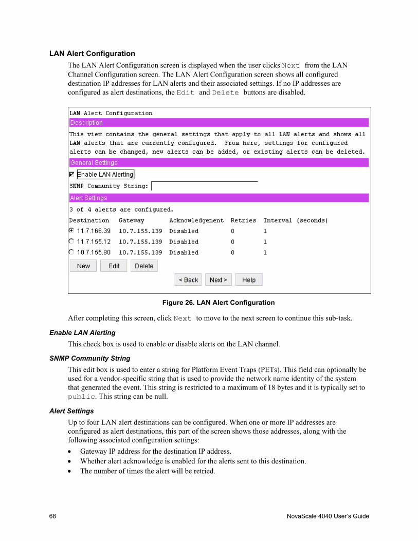
68 NovaScale 4040 User’s Guide
LAN Alert ConfigurationThe LAN Alert Configuration screen is displayed when the user clicks Next from the LANChannel Configuration screen. The LAN Alert Configuration screen shows all configureddestination IP addresses for LAN alerts and their associated settings. If no IP addresses areconfigured as alert destinations, the Edit and Delete buttons are disabled.
Figure 26. LAN Alert Configuration
After completing this screen, click Next to move to the next screen to continue this sub-task.
Enable LAN AlertingThis check box is used to enable or disable alerts on the LAN channel.
SNMP Community StringThis edit box is used to enter a string for Platform Event Traps (PETs). This field can optionally beused for a vendor-specific string that is used to provide the network name identity of the systemthat generated the event. This string is restricted to a maximum of 18 bytes and it is typically set topublic. This string can be null.
Alert SettingsUp to four LAN alert destinations can be configured. When one or more IP addresses areconfigured as alert destinations, this part of the screen shows those addresses, along with thefollowing associated configuration settings:• Gateway IP address for the destination IP address.• Whether alert acknowledge is enabled for the alerts sent to this destination.• The number of times the alert will be retried.
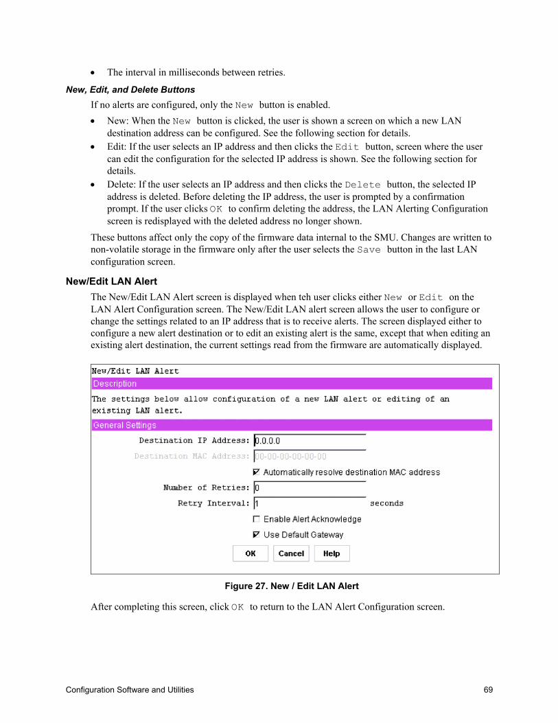
Configuration Software and Utilities 69
• The interval in milliseconds between retries.
New, Edit, and Delete ButtonsIf no alerts are configured, only the New button is enabled.• New: When the New button is clicked, the user is shown a screen on which a new LAN
destination address can be configured. See the following section for details.• Edit: If the user selects an IP address and then clicks the Edit button, screen where the user
can edit the configuration for the selected IP address is shown. See the following section fordetails.
• Delete: If the user selects an IP address and then clicks the Delete button, the selected IPaddress is deleted. Before deleting the IP address, the user is prompted by a confirmationprompt. If the user clicks OK to confirm deleting the address, the LAN Alerting Configurationscreen is redisplayed with the deleted address no longer shown.
These buttons affect only the copy of the firmware data internal to the SMU. Changes are written tonon-volatile storage in the firmware only after the user selects the Save button in the last LANconfiguration screen.
New/Edit LAN AlertThe New/Edit LAN Alert screen is displayed when teh user clicks either New or Edit on theLAN Alert Configuration screen. The New/Edit LAN alert screen allows the user to configure orchange the settings related to an IP address that is to receive alerts. The screen displayed either toconfigure a new alert destination or to edit an existing alert is the same, except that when editing anexisting alert destination, the current settings read from the firmware are automatically displayed.
Figure 27. New / Edit LAN Alert
After completing this screen, click OK to return to the LAN Alert Configuration screen.

70 NovaScale 4040 User’s Guide
Destination IP AddressThis edit box allows the user to enter the IP address to which an alert is to be sent. The IP address isentered as a dotted notation, such as 192.168.0.2. The SMU does not check whether an IP addressmatches a previously entered address.
Destination MAC AddressThis edit box is used to enter the MAC address of the destination machine to which the alert shouldbe sent. This box is used when the destination IP address is outside the subnet that the server is on.
The MAC address should be entered as a series of six pairs of hex digits separated by dashes, suchas 00-01-62-d0-3e-66. Alphabetic hex digits (a-f) can be entered in uppercase or lowercase. Thisedit box is disabled by default and is only activated if the check box is not checked forAutomatically will resolve destination MAC address.
Automatically Resolve Destination MAC AddressThis check box allows the user to specify whether the BMC should automatically attempt to resolvethe MAC address of the destination system. This box is checked by default unless the MAC addressedit box appears to include a valid MAC address.
If this box is not checked, the MAC address in the Destination MAC Address field must beprovided.
When the OK button is clicked, the firmware attempts to resolve the destination MAC address. Ifthe BMC cannot resolve the address, the screen is redisplayed with the box unchecked and the useris asked to provide the MAC address in the Destination Gateway MAC Address field. If the screenis redisplayed due to a MAC address resolution issue, any user data previously entered, other thanthe MAC address information, remains in place.
Number of RetriesThis edit box allows the number of times to retry sending an alert to a given destination to beentered. If alert acknowledge is enabled, then retries are sent only if a timeout occurs while waitingfor the acknowledgement. If alert acknowledge is disabled, the number of retries is equal to thenumber of times an unacknowledged alert is sent out.
If the number of retries is set to 0, only a single attempt is made to send the alert. When a numbergreater than 0 is entered, the alert will be retried only if a timeout occurs while waiting for theacknowledgement.
The number of retries must be between zero and seven.
Retry IntervalThis edit box is used to set the retry interval for sending an alert or to set the acknowledge timeoutwhen Enable Alert Acknowledge is enabled. The value entered into this field is disregarded ifEnable Alert Acknowledge is disabled.
The retry interval is in seconds, with a recommended value of three seconds. The retry value mustbe between 1 and 255.
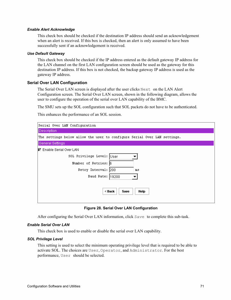
Configuration Software and Utilities 71
Enable Alert AcknowledgeThis check box should be checked if the destination IP address should send an acknowledgementwhen an alert is received. If this box is checked, then an alert is only assumed to have beensuccessfully sent if an acknowledgement is received.
Use Default GatewayThis check box should be checked if the IP address entered as the default gateway IP address forthe LAN channel on the first LAN configuration screen should be used as the gateway for thisdestination IP address. If this box is not checked, the backup gateway IP address is used as thegateway IP address.
Serial Over LAN ConfigurationThe Serial Over LAN screen is displayed after the user clicks Next on the LAN AlertConfiguration screen. The Serial Over LAN screen, shown in the following diagram, allows theuser to configure the operation of the serial over LAN capability of the BMC.
The SMU sets up the SOL configuration such that SOL packets do not have to be authenticated.
This enhances the performance of an SOL session.
Figure 28. Serial Over LAN Configuration
After configuring the Serial Over LAN information, click Save to complete this sub-task.
Enable Serial Over LANThis check box is used to enable or disable the serial over LAN capability.
SOL Privilege LevelThis setting is used to select the minimum operating privilege level that is required to be able toactivate SOL. The choices are User, Operator, and Administrator. For the bestperformance, User should be selected.

72 NovaScale 4040 User’s Guide
Number of RetriesThis field sets the number of times that the BMC tries to resend a SOL message to a remoteconsole.
The number of retries must be between zero and seven.
Retry IntervalThis field sets the number of milliseconds that the BMC waits between trying to send SOLmessages to a remote client.
The value entered must be between 0 and 2559. The SMU truncates the digit in the ones columnfrom any input number because the firmware maintains this value in 10 millisecond intervals.
Therefore, any value that is entered between 0 and 9 is displayed as 0.
Baud RateThis field sets the baud rate at which serial data is transferred by the BMC when SOL is active.
The choices are Default IPMI, 9600 bps, 19.2 kbps, 38.4 kbps, 57.6, and 115.2kbps. If Default IPMI is selected, the baud rate used is the rate currently set for BIOS serialredirection. When SOL is active, serial communication with the BMC always occurs with eightdata bits, no parity, one stop bit, and RTS/CTS (hardware) flow control.
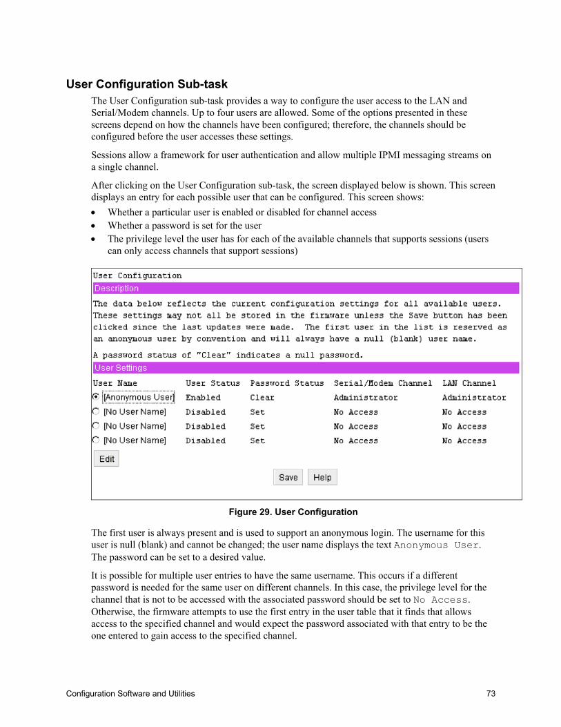
Configuration Software and Utilities 73
User Configuration Sub-taskThe User Configuration sub-task provides a way to configure the user access to the LAN andSerial/Modem channels. Up to four users are allowed. Some of the options presented in thesescreens depend on how the channels have been configured; therefore, the channels should beconfigured before the user accesses these settings.
Sessions allow a framework for user authentication and allow multiple IPMI messaging streams ona single channel.
After clicking on the User Configuration sub-task, the screen displayed below is shown. This screendisplays an entry for each possible user that can be configured. This screen shows:• Whether a particular user is enabled or disabled for channel access• Whether a password is set for the user• The privilege level the user has for each of the available channels that supports sessions (users
can only access channels that support sessions)
Figure 29. User Configuration
The first user is always present and is used to support an anonymous login. The username for thisuser is null (blank) and cannot be changed; the user name displays the text Anonymous User.The password can be set to a desired value.
It is possible for multiple user entries to have the same username. This occurs if a differentpassword is needed for the same user on different channels. In this case, the privilege level for thechannel that is not to be accessed with the associated password should be set to No Access.Otherwise, the firmware attempts to use the first entry in the user table that it finds that allowsaccess to the specified channel and would expect the password associated with that entry to be theone entered to gain access to the specified channel.
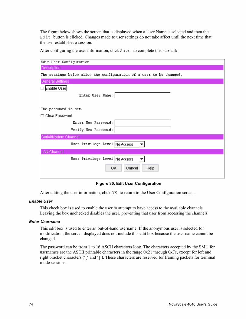
74 NovaScale 4040 User’s Guide
The figure below shows the screen that is displayed when a User Name is selected and then theEdit button is clicked. Changes made to user settings do not take affect until the next time thatthe user establishes a session.
After configuring the user information, click Save to complete this sub-task.
Figure 30. Edit User Configuration
After editing the user information, click OK to return to the User Configuration screen.
Enable UserThis check box is used to enable the user to attempt to have access to the available channels.Leaving the box unchecked disables the user, preventing that user from accessing the channels.
Enter UsernameThis edit box is used to enter an out-of-band username. If the anonymous user is selected formodification, the screen displayed does not include this edit box because the user name cannot bechanged.
The password can be from 1 to 16 ASCII characters long. The characters accepted by the SMU forusernames are the ASCII printable characters in the range 0x21 through 0x7e, except for left andright bracket characters (‘[‘ and ‘]’). These characters are reserved for framing packets for terminalmode sessions.

Configuration Software and Utilities 75
Clear PasswordThis check box is used to clear the password for the user. If this box is checked, the Enter andVerify New Password edit boxes are disabled.
Enter/Verify New PasswordThese edit boxes allow the user to enter the password for the user. The Verify New Password editbox ensures that the password entered in the Enter New Password edit box is correct. As a userenters a password, asterisks are displayed. If a password already exists, these fields show******** when the user enters this screen.
This password can be between 1 and 16 ASCII characters in length. The characters accepted by theSMU for user passwords are the ASCII printable characters in the range 0x21 through 0x7e, exceptfor left and right bracket characters ( [ and ]), since those characters are used for framing packetsfor terminal mode sessions.
Note that if the Clear Password check box is checked, these two edit boxes are disabled.
If a user password is currently set, the SMU user is not required to enter the current passwordbefore changing it.
User Privilege Level for LAN ChannelsThis combo box allows the user to select the privilege level for the LAN channel. The globalprivilege level set for the LAN channel access takes precedence over the user privilege level. Forexample, if the LAN channel is configured for user access only, then users are limited to useroperations regardless of the user privilege level.
User Privilege Level for Serial/Modem ChannelThis combo box allows the user to select the privilege level for serial/modem channel access. Theprivilege level set for the serial/modem channel takes precedence over the user privilege level. Forexample, if the serial/modem channel is configured for user access only, then users are limited touser operations regardless of the user privilege level.
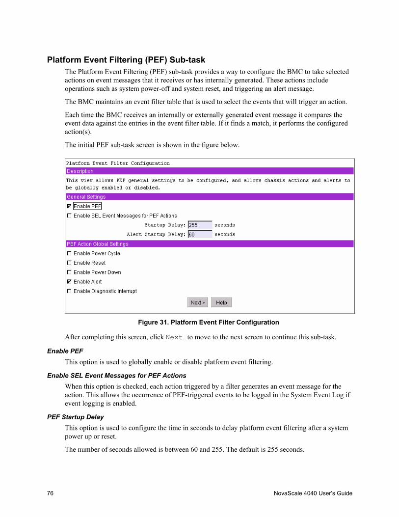
76 NovaScale 4040 User’s Guide
Platform Event Filtering (PEF) Sub-taskThe Platform Event Filtering (PEF) sub-task provides a way to configure the BMC to take selectedactions on event messages that it receives or has internally generated. These actions includeoperations such as system power-off and system reset, and triggering an alert message.
The BMC maintains an event filter table that is used to select the events that will trigger an action.
Each time the BMC receives an internally or externally generated event message it compares theevent data against the entries in the event filter table. If it finds a match, it performs the configuredaction(s).
The initial PEF sub-task screen is shown in the figure below.
Figure 31. Platform Event Filter Configuration
After completing this screen, click Next to move to the next screen to continue this sub-task.
Enable PEFThis option is used to globally enable or disable platform event filtering.
Enable SEL Event Messages for PEF ActionsWhen this option is checked, each action triggered by a filter generates an event message for theaction. This allows the occurrence of PEF-triggered events to be logged in the System Event Log ifevent logging is enabled.
PEF Startup DelayThis option is used to configure the time in seconds to delay platform event filtering after a systempower up or reset.
The number of seconds allowed is between 60 and 255. The default is 255 seconds.

Configuration Software and Utilities 77
Alert Startup DelayThis setting is used to configure the time in seconds to delay sending out alerts after a system powerup or reset.
The number of seconds allowed is between 60 and 255. Zero indicates no delay.
PEF Action Global SettingsThis set of check boxes globally enables PEF actions that can occur when an event filter istriggered. For a filter to trigger a particular chassis action (power cycle, reset, power down, ordiagnostic interrupt) the global setting must be enabled and the specific chassis action must beselected for the filter. The chassis actions are configured in the screen that appears after the userclicks Next.
The check boxes allow enabling or disabling of the following:• Power Cycle: This check box globally enables / disables the Power Cycle action when an event
filter is triggered. The action is enabled when the box is checked.• Reset: This check box globally enables / disables the system reset action when an event filter is
triggered. The action is enabled when the box is checked.• Power Down: This check box globally enables / disables the system power down action when
an event filter is triggered. The action is enabled when the box is checked.• Diagnostic Interrupt: This check box globally enables / disables a diagnostic (non-maskable)
interrupt when an event filter is triggered. The action is enabled with the box is checked.• Alert: This check box globally enables / disables alerts when an event filter is triggered. The
action is enabled when the box is checked.
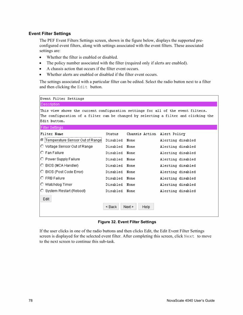
78 NovaScale 4040 User’s Guide
Event Filter SettingsThe PEF Event Filters Settings screen, shown in the figure below, displays the supported pre-configured event filters, along with settings associated with the event filters. These associatedsettings are:• Whether the filter is enabled or disabled.• The policy number associated with the filter (required only if alerts are enabled).• A chassis action that occurs if the filter event occurs.• Whether alerts are enabled or disabled if the filter event occurs.
The settings associated with a particular filter can be edited. Select the radio button next to a filterand then clicking the Edit button.
Figure 32. Event Filter Settings
If the user clicks in one of the radio buttons and then clicks Edit, the Edit Event Filter Settingsscreen is displayed for the selected event filter. After completing this screen, click Next to moveto the next screen to continue this sub-task.
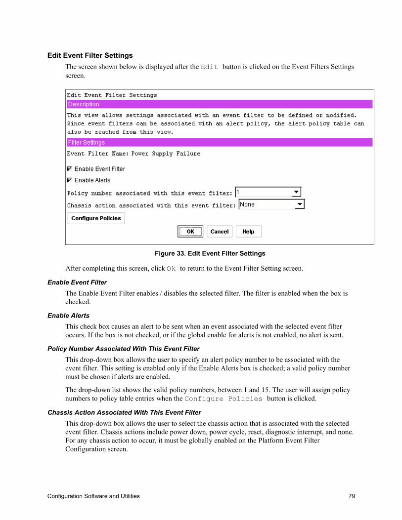
Configuration Software and Utilities 79
Edit Event Filter SettingsThe screen shown below is displayed after the Edit button is clicked on the Event Filters Settingsscreen.
Figure 33. Edit Event Filter Settings
After completing this screen, click Ok to return to the Event Filter Setting screen.
Enable Event FilterThe Enable Event Filter enables / disables the selected filter. The filter is enabled when the box ischecked.
Enable AlertsThis check box causes an alert to be sent when an event associated with the selected event filteroccurs. If the box is not checked, or if the global enable for alerts is not enabled, no alert is sent.
Policy Number Associated With This Event FilterThis drop-down box allows the user to specify an alert policy number to be associated with theevent filter. This setting is enabled only if the Enable Alerts box is checked; a valid policy numbermust be chosen if alerts are enabled.
The drop-down list shows the valid policy numbers, between 1 and 15. The user will assign policynumbers to policy table entries when the Configure Policies button is clicked.
Chassis Action Associated With This Event FilterThis drop-down box allows the user to select the chassis action that is associated with the selectedevent filter. Chassis actions include power down, power cycle, reset, diagnostic interrupt, and none.For any chassis action to occur, it must be globally enabled on the Platform Event FilterConfiguration screen.

80 NovaScale 4040 User’s Guide
Configure Policies ButtonThis button provides access to the screen that displays the current settings of all entries in the policytable, where the user defines the settings associated with the policy numbers used in the Policynumber associated with this event filter drop-down box.
Alert Policy TableThe figure on the following page shows all the entries in the alert policy table, regardless ofwhether any settings are associated with a particular entry. All entries are shown because the entriesin the table are order-dependent, so that when an alert occurs, entries in the table are processedfrom top to bottom as the firmware attempts to match table entries with the policy numberassociated with the event that caused the alert. By seeing all entries, the user is able to ensure thatthe entries are in the correct order.
One use of the policy table is to be able to specify multiple destinations for alerts that occur. Thiscan be done by assigning the same policy number to multiple entries in the table; but specifyingdifferent destinations in the destination field. If one policy is associated with multiple entries in thepolicy table, the user can further refine the destinations that receive alerts by using the policy type.
Because the firmware goes through the table in order from top to bottom, when an event occurs, thetable is searched in order for entries in which the policy number matches the policy numberassociated with the event filter. Therefore, the alert is sent to the destinations in the order in whichthey are encountered in the policy table. Make sure the destinations appear in the table in thedesired order.
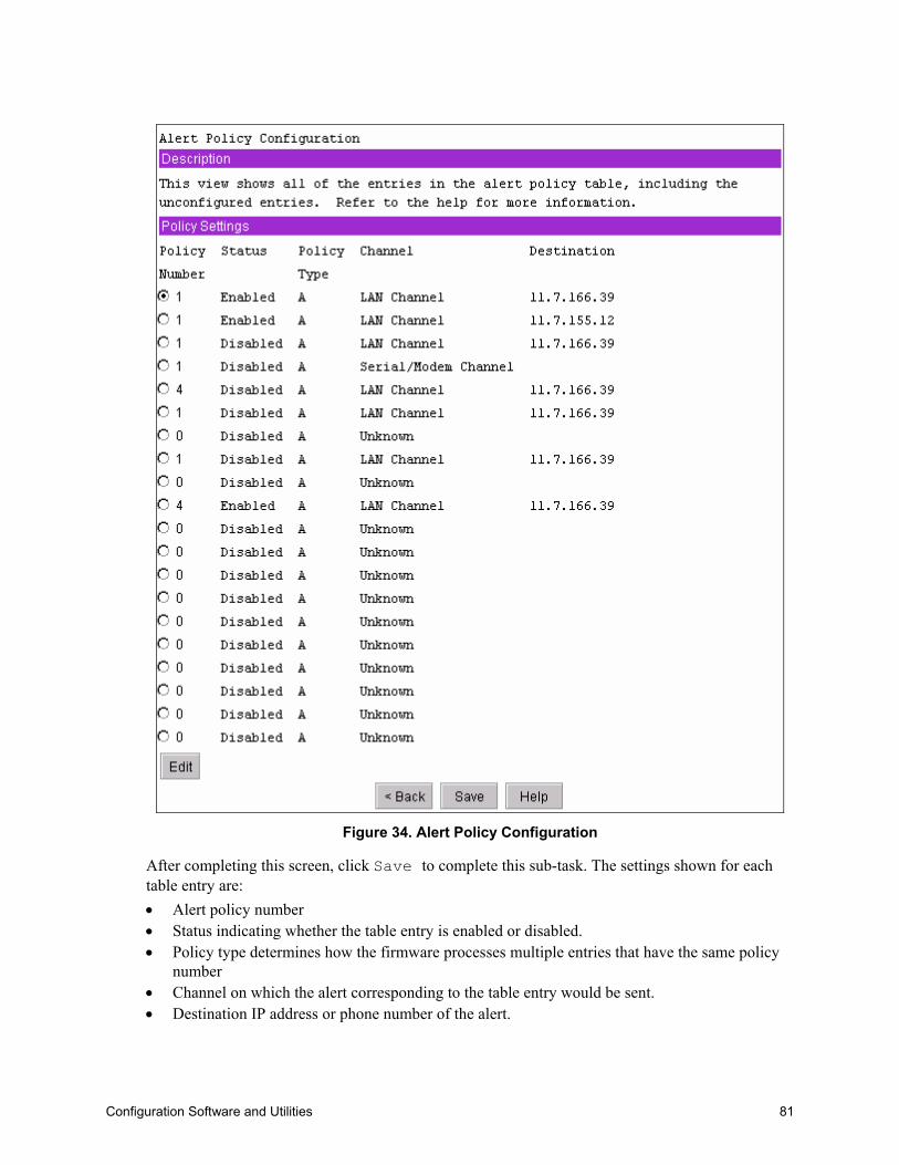
Configuration Software and Utilities 81
Figure 34. Alert Policy Configuration
After completing this screen, click Save to complete this sub-task. The settings shown for eachtable entry are:• Alert policy number• Status indicating whether the table entry is enabled or disabled.• Policy type determines how the firmware processes multiple entries that have the same policy
number• Channel on which the alert corresponding to the table entry would be sent.• Destination IP address or phone number of the alert.
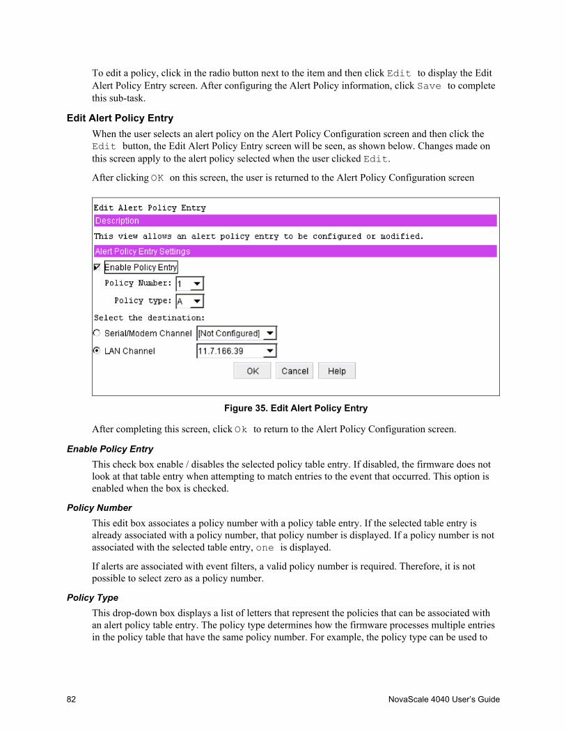
82 NovaScale 4040 User’s Guide
To edit a policy, click in the radio button next to the item and then click Edit to display the EditAlert Policy Entry screen. After configuring the Alert Policy information, click Save to completethis sub-task.
Edit Alert Policy EntryWhen the user selects an alert policy on the Alert Policy Configuration screen and then click theEdit button, the Edit Alert Policy Entry screen will be seen, as shown below. Changes made onthis screen apply to the alert policy selected when the user clicked Edit.
After clicking OK on this screen, the user is returned to the Alert Policy Configuration screen
Figure 35. Edit Alert Policy Entry
After completing this screen, click Ok to return to the Alert Policy Configuration screen.
Enable Policy EntryThis check box enable / disables the selected policy table entry. If disabled, the firmware does notlook at that table entry when attempting to match entries to the event that occurred. This option isenabled when the box is checked.
Policy NumberThis edit box associates a policy number with a policy table entry. If the selected table entry isalready associated with a policy number, that policy number is displayed. If a policy number is notassociated with the selected table entry, one is displayed.
If alerts are associated with event filters, a valid policy number is required. Therefore, it is notpossible to select zero as a policy number.
Policy TypeThis drop-down box displays a list of letters that represent the policies that can be associated withan alert policy table entry. The policy type determines how the firmware processes multiple entriesin the policy table that have the same policy number. For example, the policy type can be used to
Configuration Software and Utilities 83
indicate whether an alert is to be sent to multiple destinations or to destinations involving the samechannel. The policy choices are listed below:• A: Always send an alert to the destination referenced in this policy table entry.• B: If the alert to the previous destination was successful, do not send an alert to the destination
referenced in the current policy table entry. Instead, proceed to the next entry in the policy tablethat has the same policy number.
• C: If the alert to the previous destination was successful, do not send an alert to the destinationreferenced in the current policy table entry. Stop processing policy table entries.
• D: If the alert to the previous destination was successful, do not send an alert to the destinationreferenced in the current policy table entry. Instead, proceed to the next policy table entry thathas the same policy number, but has a different channel destination.
• E: If the alert to the previous destination was successful, do not send an alert to the destinationreferenced in the current policy table entry. Instead, proceed to the next policy table entry withthe same policy number that has a different destination type.
Select the DestinationThis set of radio buttons shows the possible channel destinations that can be associated with apolicy table entry. Each radio button is associated with a drop-down list of destinations that havebeen configured for that channel. Only the selection made in the drop-down list associated with theactive radio button (channel) is used.
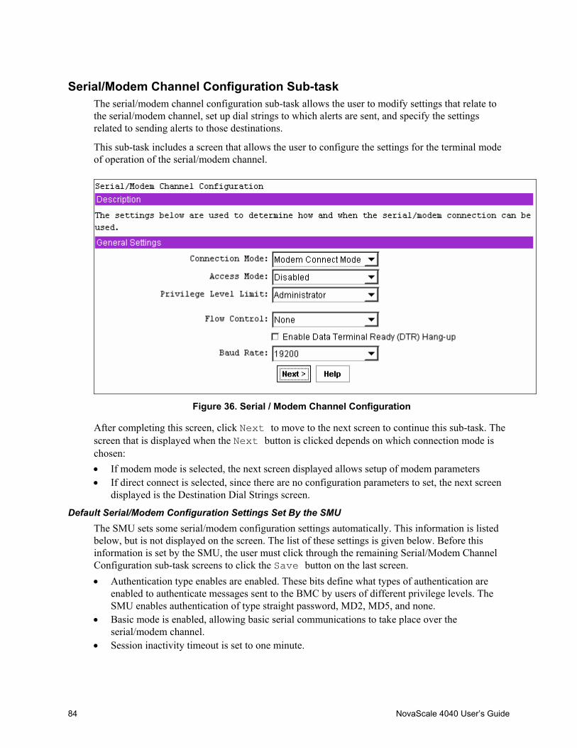
84 NovaScale 4040 User’s Guide
Serial/Modem Channel Configuration Sub-taskThe serial/modem channel configuration sub-task allows the user to modify settings that relate tothe serial/modem channel, set up dial strings to which alerts are sent, and specify the settingsrelated to sending alerts to those destinations.
This sub-task includes a screen that allows the user to configure the settings for the terminal modeof operation of the serial/modem channel.
Figure 36. Serial / Modem Channel Configuration
After completing this screen, click Next to move to the next screen to continue this sub-task. Thescreen that is displayed when the Next button is clicked depends on which connection mode ischosen:• If modem mode is selected, the next screen displayed allows setup of modem parameters• If direct connect is selected, since there are no configuration parameters to set, the next screen
displayed is the Destination Dial Strings screen.
Default Serial/Modem Configuration Settings Set By the SMUThe SMU sets some serial/modem configuration settings automatically. This information is listedbelow, but is not displayed on the screen. The list of these settings is given below. Before thisinformation is set by the SMU, the user must click through the remaining Serial/Modem ChannelConfiguration sub-task screens to click the Save button on the last screen.• Authentication type enables are enabled. These bits define what types of authentication are
enabled to authenticate messages sent to the BMC by users of different privilege levels. TheSMU enables authentication of type straight password, MD2, MD5, and none.
• Basic mode is enabled, allowing basic serial communications to take place over theserial/modem channel.
• Session inactivity timeout is set to one minute.

Configuration Software and Utilities 85
• Session termination bits are enabled to enable ending of a serial/modem session if an inactivitytimeout occurs or if DCD is lost.
• Flow control and baud rate are set for IPMI messaging (flow control is set to hardware flowcontrol; the baud rate is set to 19.2 kbps).
• The multiplexor that determines who controls the serial connector has various default settingsenabled and disabled.
Connection ModeThe connection mode determines the protocols used when performing IPMI messaging to the BMC.After selecting a connection mode, clicking on the Next button displays the screen for theselected mode.• Direct Connect Mode: When Direct Connect Mode is selected, the client console and target
server are connected by a null modem cable attached between the serial ports of each system.• Modem Mode: When Modem Mode is selected, the client system establishes a connection to
the target server using a modem. Each system must have a modem attached, and the user on theclient system must have the dial string for the modem connected to the target server.
Access ModeThis option is used to configure the access mode for the Serial/Modem channel. The choices are:• Pre-boot only: The Serial/Modem channel is available only out-of-band while the machine is
powered-off and during POST until the boot process is initiated. This option is primarily usedwith serial port sharing where it may be desirable to ensure that the BMC does not control theserial port while the operating system is running. The Pre-boot only setting does not affectSerial/Modem alerting. If alerting is enabled and software does not handle the event, the BMCtakes control of the port for the time that it takes to deliver the alert.
• Always Available: The channel is dedicated to communication with the BMC and is availableduring all system states (powered-down, powered-up, pre-boot, sleep, run-time, etc.).
• Shared: Shared is the same as Always Available, but the BIOS leaves the serial port availablefor software use.
• Disabled: The channel is not allowed to communicate with the BMC except for alerting.
Privilege Level LimitThis is the maximum privilege level that users can have on this channel. It restricts users of thechannel to a set of BMC commands that can be issued at that privilege level. For example, if thechannel privilege limit is configured with a maximum privilege level of Operator, and a user isconfigured to have Administrator privilege, that user can still only execute Operator levelcommands over this channel. See the LAN Channel Configuration Sub-task for a description of theprivilege levels.
IPMI Messaging Communication SettingsThese parameters are the global settings for IPMI messaging, which include Direct Connect andModem modes. IPMI messaging always occurs with 8 bits/character, no parity, and 1 stop bit. TheCOM settings that can be configured are:• Flow Control: This option sets how the flow of data is controlled. Available choices are No
Flow Control, CTS/RTS (hardware handshake), and XON/XOFF.• Baud Rate: This option sets the maximum rate in bits per second at which the data can be
transmitted through the serial port. Available baud rates are 9600, 19200, 38400, 57600, and
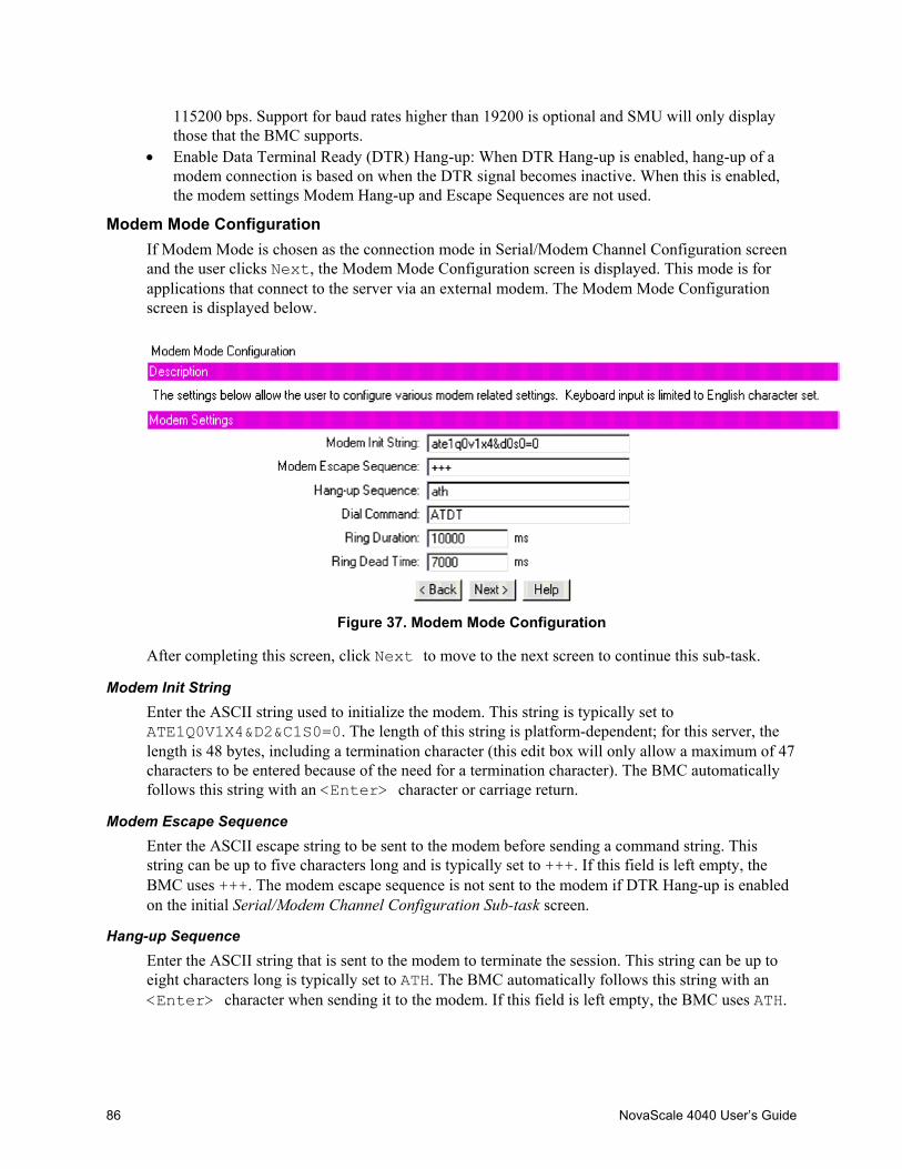
86 NovaScale 4040 User’s Guide
115200 bps. Support for baud rates higher than 19200 is optional and SMU will only displaythose that the BMC supports.
• Enable Data Terminal Ready (DTR) Hang-up: When DTR Hang-up is enabled, hang-up of amodem connection is based on when the DTR signal becomes inactive. When this is enabled,the modem settings Modem Hang-up and Escape Sequences are not used.
Modem Mode ConfigurationIf Modem Mode is chosen as the connection mode in Serial/Modem Channel Configuration screenand the user clicks Next, the Modem Mode Configuration screen is displayed. This mode is forapplications that connect to the server via an external modem. The Modem Mode Configurationscreen is displayed below.
Figure 37. Modem Mode Configuration
After completing this screen, click Next to move to the next screen to continue this sub-task.
Modem Init StringEnter the ASCII string used to initialize the modem. This string is typically set toATE1Q0V1X4&D2&C1S0=0. The length of this string is platform-dependent; for this server, thelength is 48 bytes, including a termination character (this edit box will only allow a maximum of 47characters to be entered because of the need for a termination character). The BMC automaticallyfollows this string with an <Enter> character or carriage return.
Modem Escape SequenceEnter the ASCII escape string to be sent to the modem before sending a command string. Thisstring can be up to five characters long and is typically set to +++. If this field is left empty, theBMC uses +++. The modem escape sequence is not sent to the modem if DTR Hang-up is enabledon the initial Serial/Modem Channel Configuration Sub-task screen.
Hang-up SequenceEnter the ASCII string that is sent to the modem to terminate the session. This string can be up toeight characters long is typically set to ATH. The BMC automatically follows this string with an<Enter> character when sending it to the modem. If this field is left empty, the BMC uses ATH.

Configuration Software and Utilities 87
The hang-up sequence is not sent to the modem if DTR Hang-up is enabled on the initialSerial/Modem Channel Configuration Sub-task screen.
Dial CommandEnter the ASCII string for the modem string used to initiate a dial sequence with the modem. If thisparameter is left empty, the BMC uses ATD.
Ring DurationThe Modem Ring Time setting specifies the time it takes the BMC to claim the serial connectionafter detecting the phone ringing while monitoring the Ring Indicator (RI) line. By configuring theRing Duration, the user can specify the amount of time that the BMC takes to switch the mux whenRI is first detected. The ring duration and ring dead time have meaning only when the serial/modemchannel access mode is set to shared.
The default values that are stored in firmware need to be adjusted for the phone in the region wherethe server/modem is located. The suggested ring duration for a US phone is 10000 ms.
The ring duration value should be entered in 500 ms increments; the SMU will round entries downto the nearest 500 ms. A value of 0 configures the BMC to switch the mux immediately on the firstdetected transition of RI.
The range of values entered can be in the range between 0 and 31000; be aware that the SMUrounds values down to the nearest 500 ms.
Ring Dead TimeThis setting allows the user to specify the amount of time that the RI signal must be deassertedbefore the BMC determines that ringing has stopped. The ring duration and ring dead time havemeaning only when the serial/modem channel access mode is set to shared.
The ring duration value should be entered in 500 ms increments and the SMU will round entriesdown to the nearest 500 ms. A value of 0 configures the BMC to switch the mux immediately onthe first detected transition of RI. The value entered should reflect any dependencies on modemtype, location of server, and the phone line carrier.
The default values that are stored in firmware need to be adjusted for the phone in the region wherethe server/modem is located. The suggested ring dead time for a US phone is 7000 ms.
The range of values entered can be in the range between 500 and 8000; be aware that the SMUrounds values down to the nearest 500 ms.
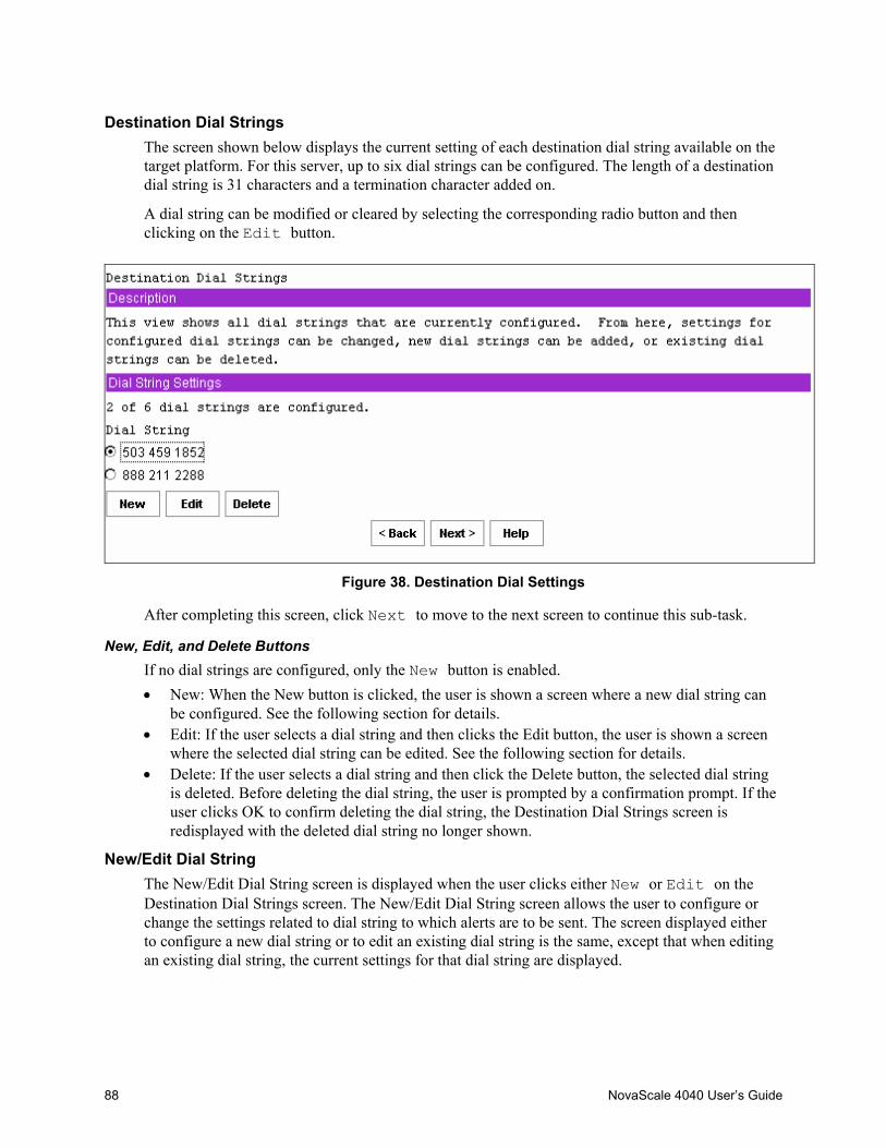
88 NovaScale 4040 User’s Guide
Destination Dial StringsThe screen shown below displays the current setting of each destination dial string available on thetarget platform. For this server, up to six dial strings can be configured. The length of a destinationdial string is 31 characters and a termination character added on.
A dial string can be modified or cleared by selecting the corresponding radio button and thenclicking on the Edit button.
Figure 38. Destination Dial Settings
After completing this screen, click Next to move to the next screen to continue this sub-task.
New, Edit, and Delete ButtonsIf no dial strings are configured, only the New button is enabled.• New: When the New button is clicked, the user is shown a screen where a new dial string can
be configured. See the following section for details.• Edit: If the user selects a dial string and then clicks the Edit button, the user is shown a screen
where the selected dial string can be edited. See the following section for details.• Delete: If the user selects a dial string and then click the Delete button, the selected dial string
is deleted. Before deleting the dial string, the user is prompted by a confirmation prompt. If theuser clicks OK to confirm deleting the dial string, the Destination Dial Strings screen isredisplayed with the deleted dial string no longer shown.
New/Edit Dial StringThe New/Edit Dial String screen is displayed when the user clicks either New or Edit on theDestination Dial Strings screen. The New/Edit Dial String screen allows the user to configure orchange the settings related to dial string to which alerts are to be sent. The screen displayed eitherto configure a new dial string or to edit an existing dial string is the same, except that when editingan existing dial string, the current settings for that dial string are displayed.
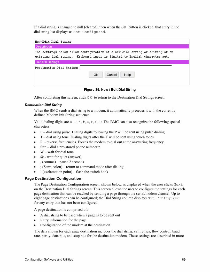
Configuration Software and Utilities 89
If a dial string is changed to null (cleared), then when the OK button is clicked, that entry in thedial string list displays as Not Configured.
Figure 39. New / Edit Dial String
After completing this screen, click OK to return to the Destination Dial Strings screen.
Destination Dial StringWhen the BMC sends a dial string to a modem, it automatically precedes it with the currentlydefined Modem Init String sequence.
Valid dialing digits are 0-9, *, #, A, B, C, D. The BMC can also recognize the following specialcharacters:• P – dial using pulse. Dialing digits following the P will be sent using pulse dialing.• T – dial using tone. Dialing digits after the T will be sent using touch tones.• R – reverse frequencies. Forces the modem to dial out at the answering frequency.• S=n – dial a pre-stored phone number n.• W – wait for dial tone.• @ - wait for quiet (answer).• , (comma) – pause 2 seconds.• ; (Semi-colon) – return to command mode after dialing.• ! (exclamation point) – flash the switch hook
Page Destination ConfigurationThe Page Destination Configuration screen, shown below, is displayed when the user clicks Nexton the Destination Dial Strings screen. This screen allows the user to configure the settings for eachpage destination that can be reached by sending a page through the serial/modem channel. Up toeight page destinations can be configured; the Dial String column displays Not Configuredfor any entry that has not been configured.
A page destination is comprised of:• A dial string to be used when a page is to be sent out• Retry information for the page• Configuration of the modem at the destination
The data shown for each page destination includes the dial string, call retries, flow control, baudrate, parity, data bits, and stop bits for the destination modem. These settings are described in more
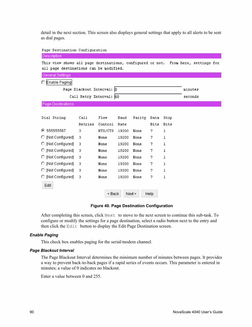
90 NovaScale 4040 User’s Guide
detail in the next section. This screen also displays general settings that apply to all alerts to be sentas dial pages.
Figure 40. Page Destination Configuration
After completing this screen, click Next to move to the next screen to continue this sub-task. Toconfigure or modify the settings for a page destination, select a radio button next to the entry andthen click the Edit button to display the Edit Page Destination screen.
Enable PagingThis check box enables paging for the serial/modem channel.
Page Blackout IntervalThe Page Blackout Interval determines the minimum number of minutes between pages. It providesa way to prevent back-to-back pages if a rapid series of events occurs. This parameter is entered inminutes; a value of 0 indicates no blackout.
Enter a value between 0 and 255.
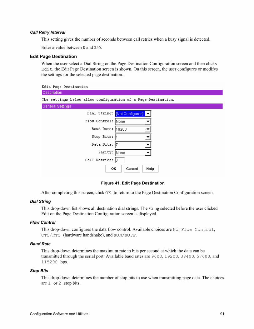
Configuration Software and Utilities 91
Call Retry IntervalThis setting gives the number of seconds between call retries when a busy signal is detected.
Enter a value between 0 and 255.
Edit Page DestinationWhen the user select a Dial String on the Page Destination Configuration screen and then clicksEdit, the Edit Page Destination screen is shown. On this screen, the user configures or modifysthe settings for the selected page destination.
Figure 41. Edit Page Destination
After completing this screen, click OK to return to the Page Destination Configuration screen.
Dial StringThis drop-down list shows all destination dial strings. The string selected before the user clickedEdit on the Page Destination Configuration screen is displayed.
Flow ControlThis drop-down configures the data flow control. Available choices are No Flow Control,CTS/RTS (hardware handshake), and XON/XOFF.
Baud RateThis drop-down determines the maximum rate in bits per second at which the data can betransmitted through the serial port. Available baud rates are 9600, 19200, 38400, 57600, and115200 bps.
Stop BitsThis drop-down determines the number of stop bits to use when transmitting page data. The choicesare 1 or 2 stop bits.
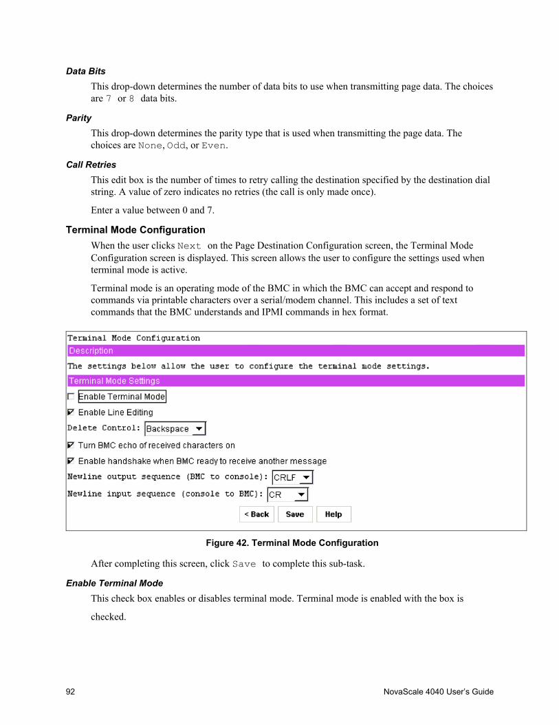
92 NovaScale 4040 User’s Guide
Data BitsThis drop-down determines the number of data bits to use when transmitting page data. The choicesare 7 or 8 data bits.
ParityThis drop-down determines the parity type that is used when transmitting the page data. Thechoices are None, Odd, or Even.
Call RetriesThis edit box is the number of times to retry calling the destination specified by the destination dialstring. A value of zero indicates no retries (the call is only made once).
Enter a value between 0 and 7.
Terminal Mode ConfigurationWhen the user clicks Next on the Page Destination Configuration screen, the Terminal ModeConfiguration screen is displayed. This screen allows the user to configure the settings used whenterminal mode is active.
Terminal mode is an operating mode of the BMC in which the BMC can accept and respond tocommands via printable characters over a serial/modem channel. This includes a set of textcommands that the BMC understands and IPMI commands in hex format.
Figure 42. Terminal Mode Configuration
After completing this screen, click Save to complete this sub-task.
Enable Terminal ModeThis check box enables or disables terminal mode. Terminal mode is enabled with the box is
checked.

Configuration Software and Utilities 93
Enable Line EditingThis check box enables or disables line editing during a terminal mode session if checked. Lineediting is enabled with the box is checked. When line editing is enabled, echo should also beenabled. When line editing is enabled:• The <Backspace> or <Delete> key can be used to delete the last character entered.• The <ESC> key can be used to delete an entire line.• Long message lines can be split across multiple-lines using a line continuation (\) character
followed immediately by <CR><LF>.
Delete ControlThis drop-down box is enabled only if the Enable Line Editing box is checked. This option allowsthe user to specify the delete control sequence for the BMC to use when <Delete> or<Backspace> is pressed. Users can choose from the following:• The BMC outputs <Delete> when <Backspace> or <Delete> is received.• The BMC outputs <Backspace><Space><Backspace> when <Backspace> or
<Delete> is received.
Turn BMC Echo of Received Characters OnThis check box allows the user to enable or disable the BMC echoing characters it receives when interminal mode. This feature is enabled when the box is checked.
Enable Handshake When BMC Ready To Receive Another MessageThis setting enables or disables whether the BMC handshakes when ready to receive anothermessage from the user. When enabled, the BMC outputs the following string when it is ready toaccept another message from the remote console:
[SYS]<newline>
Checking the box enables this feature.
Newline Output Sequence (BMC to console)This setting allows the user to select the characters that the BMC uses as a newline sequence whenthe BMC writes a line to the console when in terminal mode. The choices are• <CR><LF>• <NULL>• <CR>• <LF><CR>• <LF>• No termination sequence
Newline Input Sequence (console to BMC)This setting allows the user to select the characters the console uses as a newline sequence whenwriting to the BMC when the BMC is in terminal mode. The choices are• <CR>• <NULL>
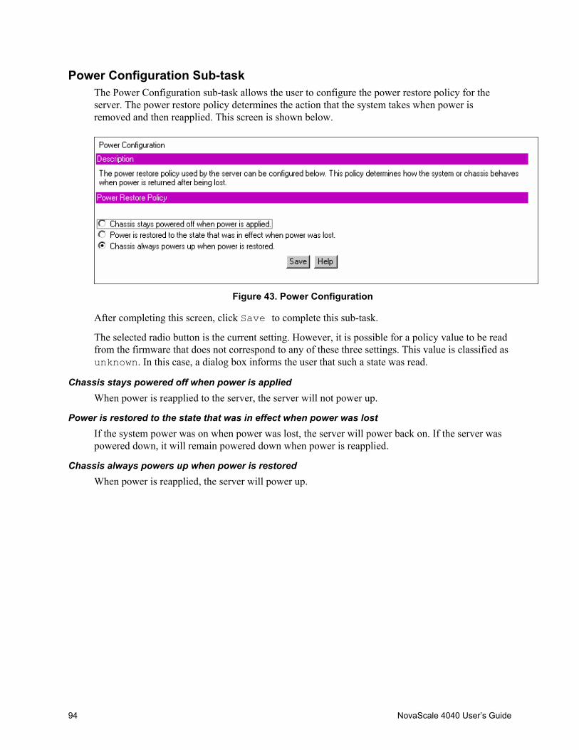
94 NovaScale 4040 User’s Guide
Power Configuration Sub-taskThe Power Configuration sub-task allows the user to configure the power restore policy for theserver. The power restore policy determines the action that the system takes when power isremoved and then reapplied. This screen is shown below.
Figure 43. Power Configuration
After completing this screen, click Save to complete this sub-task.
The selected radio button is the current setting. However, it is possible for a policy value to be readfrom the firmware that does not correspond to any of these three settings. This value is classified asunknown. In this case, a dialog box informs the user that such a state was read.
Chassis stays powered off when power is appliedWhen power is reapplied to the server, the server will not power up.
Power is restored to the state that was in effect when power was lostIf the system power was on when power was lost, the server will power back on. If the server waspowered down, it will remain powered down when power is reapplied.
Chassis always powers up when power is restoredWhen power is reapplied, the server will power up.

Configuration Software and Utilities 95
SEL Viewer
✏ NOTEThe SEL Viewer task is available only on the local version of the SMU. Thistask is not available when running the remote version of the SMU.
The SEL Viewer task allows the user to view the System Event Log. The SEL Viewer task
supports the following:• Viewing the BMC SEL• Saving a log to a file• Viewing a saved log file• Viewing the SEL properties• Clearing the BMC SEL
The SEL Viewer is started by clicking the SEL task in the task pane of the SMU. This task allowsthe user to view the current system events logged in the SEL. Upon selecting the task, the entireSEL is loaded. During the load process, a dialog displays the progress. You cannot interrupt thisprocess. After the load is completed the user will see a warning message displayed if the SEL isfull.
If the SEL is empty, the following message is displayed:
The SEL is empty, no records to display
After any messages have been dismissed, the user will see a page of events. This page containscolumn headers and as many events that can fit on screen without using scroll bars. In order toprevent long display strings from creating scrollbars in the SEL Viewer the list view restricts thelength of the following fields:• Sensor Type and Number to 20 characters• Event Description field to 30 characters• Generator ID field to 15 characters
Viewing Events in the SELWhen the SEL Viewer is opened, the first page of events is loaded from the log and displayed. Toview the remaining events the user is provided with a series of buttons along the bottom of thescreen. The <Tab> key can be used to access the screen buttons.
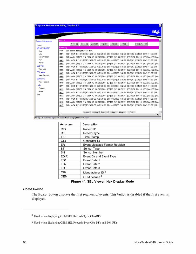
96 NovaScale 4040 User’s Guide
Acronym DescriptionRID Record IDRT Record TypeTS Time StampGID Generator IDER Event Message Format RevisionST Sensor TypeSN Sensor NumberEDIR Event Dir and Event TypeED1 Event Data 1ED2 Event Data 2ED3 Event Data 3MID Manufacturer ID 1
OEM OEM defined 2
Figure 44. SEL Viewer, Hex Display Mode
Home ButtonThe Home button displays the first segment of events. This button is disabled if the first event isdisplayed.
1 Used when displaying OEM SEL Records Type C0h-DFh
2 Used when displaying OEM SEL Records Type C0h-DFh and E0h-FFh
Configuration Software and Utilities 97
End ButtonThe End button displays the last segment of events. The number of events on this page variesbased on the number of entries in the log; it may not fill the screen. This button is disabled if thelast event is displayed.
Previous ButtonThis Previous button displays the prior segment of records. This button is disabled if the firstevent is displayed.
Next ButtonThis Next button displays the next segment of records. This button is disabled if the last event isdisplayed.
<<More ButtonThis <<More button backtracks by five segments of records. This is the equivalent of pressing thePrevious button five times. If there are not five pages to backtrack, it goes to the first page ofevents. This button is disabled if the first event is displayed.
More>> ButtonThis button advances by five segments of records. This is the equivalent of pressing the Nextbutton five times. If there are not five segments to advance through, it goes to the end segment.
This button is disabled if the last event is displayed.
Viewing Single EventsSingle events can be viewed in a modal popup window. The record to view is selected from themain screen by the link in the SEL ID field. The popup screen shows the hexadecimal view and theverbose text. The data is not limited in space, and no scrolling is required.
Sorting the SELThe SEL can be sorted by clicking on the column header the user wishs to sort by. An arrow to theright of the column header indicates the sort-by column and whether the column is sorted inascending or descending order. An up arrow indicates ascending order, and a down arrow indicatesdescending order. Clicking on the currently sorted column reverses the sort order of the column.Whenever the SEL is sorted, the first segment is displayed.
Table 20. SEL Sort Order DefinitionsSort Field Ascending Orde Descending Order
SEL ID Numeric ascending Numeric descendingTime Stamp Pre-Init time stamps first, followed by
the most recent time stamp. Pre-inittime stamps are sorted by SEL ID.
Most recent time stamp last, followed bythe pre-Init time stamps. Pre-init timestamps are sorted by SEL ID.
Sensor Name Alphabetic ascending Alphabetic descendingEvent Description Alphabetic ascending Alphabetic descendingGenerator ID Alphabetic ascending Alphabetic descending

98 NovaScale 4040 User’s Guide
Save Log ButtonThis allows the user to save the currently loaded SEL to a file. The user can choose to save the SELas the decoded event data or as hexadecimal format. A different file extension is used for each type.In each case, the SEL properties and the entire log are written to the file. The SEL properties aresaved at the top of the file and are saved as verbose text.
If the save fails because the file cannot be created, this error message is displayed:
Unable to create save file
If an error occurs while writing information to the file, this message is displayed:
Error saving SEL to the file
Open Log ButtonThis allows the user to load a currently saved log file. The loaded file can be in either decoded orhexadecimal format. Upon opening a log file, the SEL Viewer is loaded, showing the events fromthe file.
If the file to open is not a valid SEL file, this message is displayed:
Invalid SEL file
If there is an error while reading the events from the file, this message is displayed:
Error reading SEL from file
If the user loads a hexadecimal log file, the viewer interprets data as if it was loaded from thesystem. The user will have all of the functionality that is available when the data is loaded from thesystem, but the Save Log button is disabled when the log is loaded from a file.
Clear SEL ButtonThis allows the user to clear all the system SEL events. Before proceeding with the clear, the user isprompted with this message:
Do you really want to clear the SEL?
The user is given two options with this prompt, OK and Cancel. Choosing Cancel will returnthe user to the SEL Viewer main screen, choosing OK will clear the SEL. After the SEL is cleared,the log and properties are refreshed and the main screen is updated with the new SEL.
Properties ButtonThis shows the user the current properties of the SEL. Included in the properties are:• IPMI version• Number of Entries• Last Add Time• Last Erase Time• Free Space Remaining (both in bytes and number of SEL events)
A message is displayed if there is an error retrieving the SEL properties.

Configuration Software and Utilities 99
Reload ButtonThis button forces a refresh of the SEL from the system. Both the event list and the properties arerefreshed.
Display as Hex ButtonThis button is only visible when the SEL is displayed in verbose mode. This will change the eventdisplay to Hex mode.
Display as Text ButtonThis button is only visible when the SEL is displayed in Hex mode. This will change the eventdisplay to text mode.

100 NovaScale 4040 User’s Guide
SDR ViewerThe SDR task allows the user to view the current system SDR records stored in the BMC. It alsoprovides the interface to opening and saving SDR files, and to viewing the SDR properties.
✏ NOTEThe SDR Viewer task is only available on the local version of the SMU.
This task is not available when running the remote version of the application.
The SDR Viewer allows the user to view the current BMC SDRs on the target system. The SDR
Viewer task supports the following:• Viewing the BMC SDRs• Viewing the SDR properties.• Saving the SDRs to a file• Viewing a saved SDR file
When the user selects the SDR task, the SDRs are retrieved from the system. As the loadprogresses, a dialog window updates the user on the status. The user is not allowed to interrupt thisprocess.
After the load is completed, a tree view of the system SDRs is displayed. The top branches of thetree are the SDR types. Under the branches are the records of that type. Clicking on the branch willexpand and collapse it, showing or hiding the SDRs of that type. Clicking on an SDR will open awindow that contains the SDR title, value, and byte location for each field in the record.
Only SDR types that have entries are included in the SDR tree view. If the viewer determines that aSDR record is invalid, the record is ignored and the remainder of the records are added to the tree.After the tree is created, a message box displays the following message if invalid records have beenidentified:
The SDR data read from the system contained invalid records, theserecords will not be displayed by the viewer. Updating yoursystem’s SDRs may correct this problem
If all the records are valid, no message is displayed. If there was an error retrieving the SDRs fromthe system, the following message is displayed:
Error retrieving SDRs from the system
An error message is also displayed if there was an error reading the SDR properties.
The SDR tree is navigable by using the keypad. The <left arrow> key collapses a branch ifthe current selection is on a branch. If the current selection is on a leaf, the selection is moved to thebranch that contains the leaf.
The <right arrow> key expands a branch if the selection is currently on a branch. If theselection is not on a branch, there is no affect. The <space bar> and <Enter> keys haveidentical functionality, as follows: If the current selection is on a branch, an expanded branch
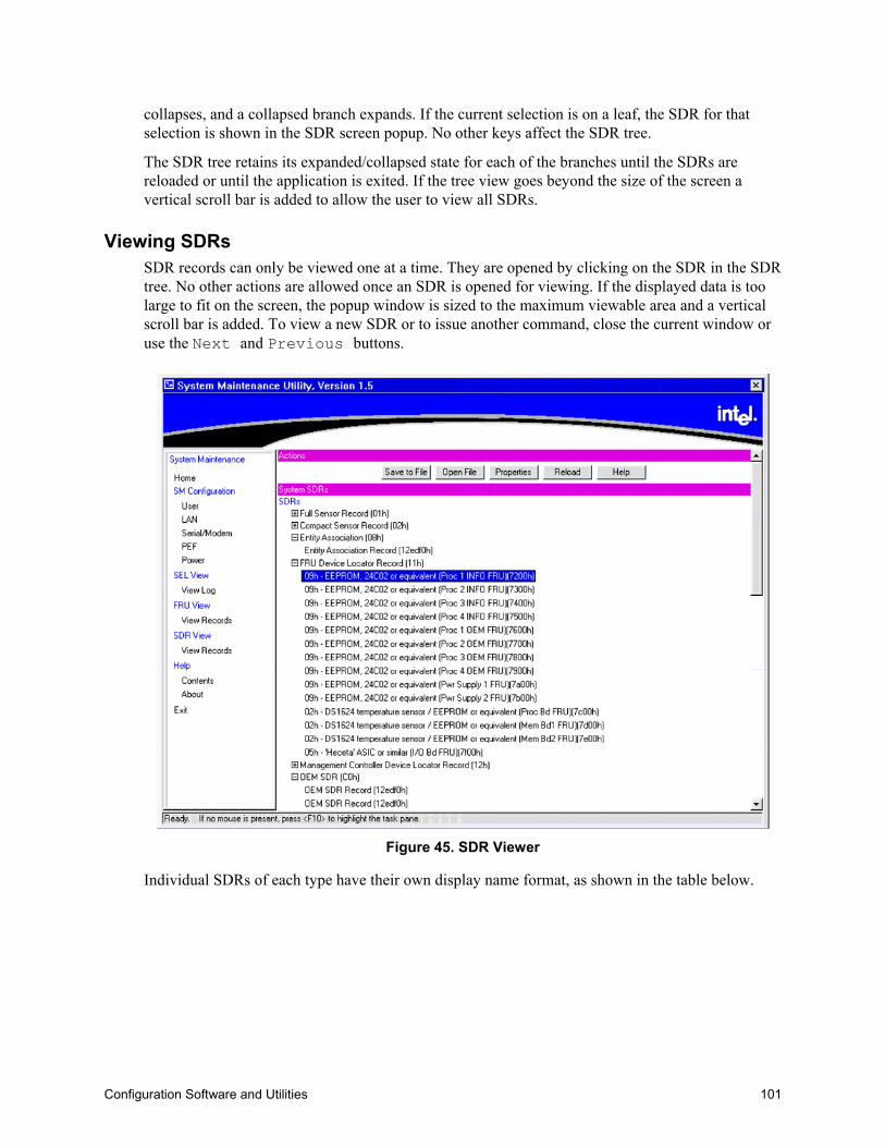
Configuration Software and Utilities 101
collapses, and a collapsed branch expands. If the current selection is on a leaf, the SDR for thatselection is shown in the SDR screen popup. No other keys affect the SDR tree.
The SDR tree retains its expanded/collapsed state for each of the branches until the SDRs arereloaded or until the application is exited. If the tree view goes beyond the size of the screen avertical scroll bar is added to allow the user to view all SDRs.
Viewing SDRsSDR records can only be viewed one at a time. They are opened by clicking on the SDR in the SDRtree. No other actions are allowed once an SDR is opened for viewing. If the displayed data is toolarge to fit on the screen, the popup window is sized to the maximum viewable area and a verticalscroll bar is added. To view a new SDR or to issue another command, close the current window oruse the Next and Previous buttons.
Figure 45. SDR Viewer
Individual SDRs of each type have their own display name format, as shown in the table below.

102 NovaScale 4040 User’s Guide
Table 21. SDR Type Name Format
SDR Type [Hex] Display Name Format
Type 1 [sensor type HEX] – [sensor type text] ([ID string]) sensor #[sensor number]
Type 2 [sensor type HEX] – [sensor type text] ([ID string]) sensor #[sensor number]
Type 8 [sensor type HEX] – [sensor type text] ([ID string])
Type 9 [sensor type HEX] – [sensor type text] ([ID string])
Type 10 [sensor type HEX] – [sensor type text] ([ID string])
Type 11 [sensor type HEX] – [sensor type text] ([ID string])
Type 12 [Entity ID HEX] – [entity ID text] ([ID string])
Type 13 [sensor type HEX] – [sensor type text] ([ID string])
Type 14 [sensor type HEX] – [sensor type text] ([ID string])
Type C0 OEM SDR ([record ID])
The SDR type displays names in a single format: [SDR type hex] – [SDR type text] ([count ofSDRs of this type]).
Under certain circumstances, the type C0 format does not follow the rules defined above. When allthe characters of the data portion of the record are printable ASCII characters, the data area isconsidered to be a string and is used for the display name instead of the format defined in the table.
Close ButtonThis button closes the current SDR window and returns the user to the SDR selection screen.
Previous ButtonThis button closes the current SDR window and displays the previous SDR record, the previousrecord must be of the same type as the current record. If this is the first SDR record in the SDR typebranch, this button is disabled.
Next ButtonThis button closes the current popup window and displays the next SDR record in the SDR tree, thenext record must be of the same type as the current record. If this is the last SDR record in the SDRtype branch, this button is disabled.
Save To File ButtonThis button allows the user to save the current SDRs to a file. If the save fails because the filecannot be created, the following message is displayed:
Unable to create save file
If an error occurs while writing information to the file, the following message is displayed:
Error saving SDRs to the file

Configuration Software and Utilities 103
Open File ButtonThis button allows the user to open a currently saved SDR file. Upon selecting this option, allcurrently loaded SDRs are deleted and only the SDR loaded from the file are displayed. If the file isnot a valid SDR file, an error message is displayed.
Properties ButtonThis button will force a refresh of the SDR properties and display them in a dialog. Included in theproperties are: IPMI version, Number of SDRs, Last Add Time, Last Erase Time, and Free SpaceRemaining in bytes. If there is an error retrieving the SDR properties, an error message is
displayed.
Reload ButtonThis button will clear the screen of the currently loaded SDRs and reload the SDRs from the BMC.This load procedure is identical to the load procedure that occurs when the viewer is opened.

104 NovaScale 4040 User’s Guide
FRU ViewerThe FRU Viewer sub-task allows the user to view the current FRUs in the system.
✏ NOTEThe FRU Viewer task is only available on the local version of the SMU.
This task is not available when running the remote version.
The FRU Viewer allows the user to view the current system FRUs on the target system. The FRUViewer task supports the following:• Viewing the current system FRUs• Viewing the current system FRU properties.• Saving the selected FRU to a file• Viewing a saved FRU file
When the user selects the view records sub-task from the FRU menu, it immediately retrieves thesystem FRUs. In order to discover the system FRUs, the viewer must first scan the system SDRsand search the records for FRU locations.
After the scan of the SDRs is complete, the viewer starts loading the FRUs. If an error occurs whilesearching the SDRs, the viewer will try to load the FRUs based on the locator records found. Thefollowing error is displayed:
Error searching for FRU device locator records, not all FRUs maybe displayed. Updating your system’s SDRs may correct this problem
As the FRUs are loaded, a dialog window updates the user with the progress. A progress window isupdated for every FRU read. The message displayed is updated for each FRU.
After the FRUs are loaded, the FRU list and FRU area viewer are displayed. By default, the firstFRU in the list is selected and displayed. If there is an error while retrieving the FRUs, thefollowing message is displayed:
Error reading FRU at Device D Bus B ID I
D, B, and I are the values from the device locator record. This message will vary depending on theFRU type, but it will display sufficient information for the user to display/update the FRU with theFRUSDR utility.
The user is unable to stop either the FRU locator search or the FRU load process.
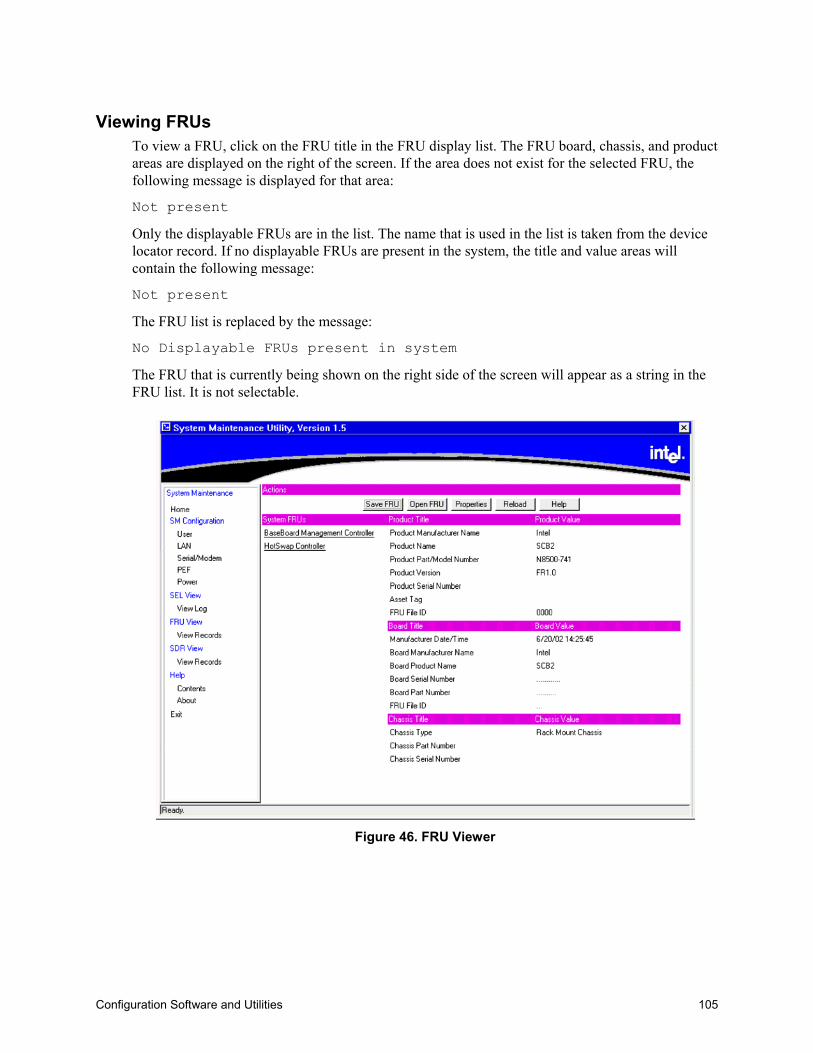
Configuration Software and Utilities 105
Viewing FRUsTo view a FRU, click on the FRU title in the FRU display list. The FRU board, chassis, and productareas are displayed on the right of the screen. If the area does not exist for the selected FRU, thefollowing message is displayed for that area:
Not present
Only the displayable FRUs are in the list. The name that is used in the list is taken from the devicelocator record. If no displayable FRUs are present in the system, the title and value areas willcontain the following message:
Not present
The FRU list is replaced by the message:
No Displayable FRUs present in system
The FRU that is currently being shown on the right side of the screen will appear as a string in theFRU list. It is not selectable.
Figure 46. FRU Viewer

106 NovaScale 4040 User’s Guide
Save To File ButtonThis button allows the user to save the currently displayed FRU to a file. If the save fails becausethe file cannot be created, this message is displayed:
Unable to create save file
If an error occurs while writing information to the file, this message is displayed:
Error saving the FRU data to the file
Open File ButtonThis button allows the user to load a currently saved FRU file. Upon selecting this option, allcurrently loaded FRUs are deleted from the screen and the loaded FRU is displayed. If the file toopen is not a valid FRU file, this message is displayed:
Invalid FRU file
If there is an error while reading the FRU from the file, this message is displayed:
Error reading FRU from file
Opening a FRU file will not affect the FRU properties.
Properties ButtonThis button will display the system FRU properties in a dialog. Included in the properties are: IPMIversion, Number of FRUs in the system, and Number of IPMI formatted FRUs in the system.
There is also a note to notify the user that only IPMI formatted FRUs are displayed.
Reload ButtonThis will clear the currently loaded FRUs and refresh the FRUs from the system. This loadprocedure is identical to the load procedure when the viewer is opened.
Help ButtonThis displays the SMU context sensitive help for the FRU Viewer.

Configuration Software and Utilities 107
Task Error HandlingDuring the execution of a task, it is possible for errors to occur. These errors may be handled indifferent ways depending on the type of error. This chapter describes how error handling operatesduring SMU task execution.
Data Entry ErrorsSome screens will ask for user input using edit boxes. In some of these boxes, the allowable userinput needs to meet certain requirements, such as use of certain characters, a maximum length, ordata within a particular range of values. The application does not check user input for validity;instead, when the user clicks a button for the next screen, the current set of data is collected andsent to the SMU core components where it is checked. If a data entry error is found, a popup dialogbox is displayed describing the error. In most cases the erroneous data is not cleared from the editbox in which it was entered. The user must clear the error and enter the correct information.
Internal Errors For Which a View Can Be GeneratedSome errors may occur during task execution that result in an operation failing but are not fatal inthat the user can still attempt to perform other tasks. These types of errors include writing the servermanagement settings to the BMC’s non-volatile storage area, for example. In such a case, a screenis displayed containing information about the error that occurred and indicating whether or not theuser may attempt the operation again. These screens also have an OK button on them.
When the user clicks OK, the last screen displayed is redisplayed. The user may also be informed asto whether the error was serious enough that the user should shut down the SMU software or rebootthe server.
Data Corruption Errors that the SMU Application can HandleData corruption errors that the SMU may be able to handle include corruption of template files usedby the SMU (files that represent UI screens to be sent from the core components to the application).In this type of case, the SMU can detect that there is a problem when it is not able to correctly parsesuch a file, which means the application is not able to correctly display a screen. For this type oferror, a message is displayed, indicating that a data corruption error has been encountered and thatthe current action cannot be completed. You are asked to select a new task from the task list.
Internal Errors For Which a View Cannot Be GeneratedIn a few cases, errors may be serious enough to prevent the SMU core components from supplyingerror information to the user. These errors may include certain types of memory allocation errorsor, in the remote case, the loss of the connection between the SMU application and the corecomponents. In such cases, the SMU application (if possible), indicates to the user that a shutdownof the software should occur and the server be rebooted.
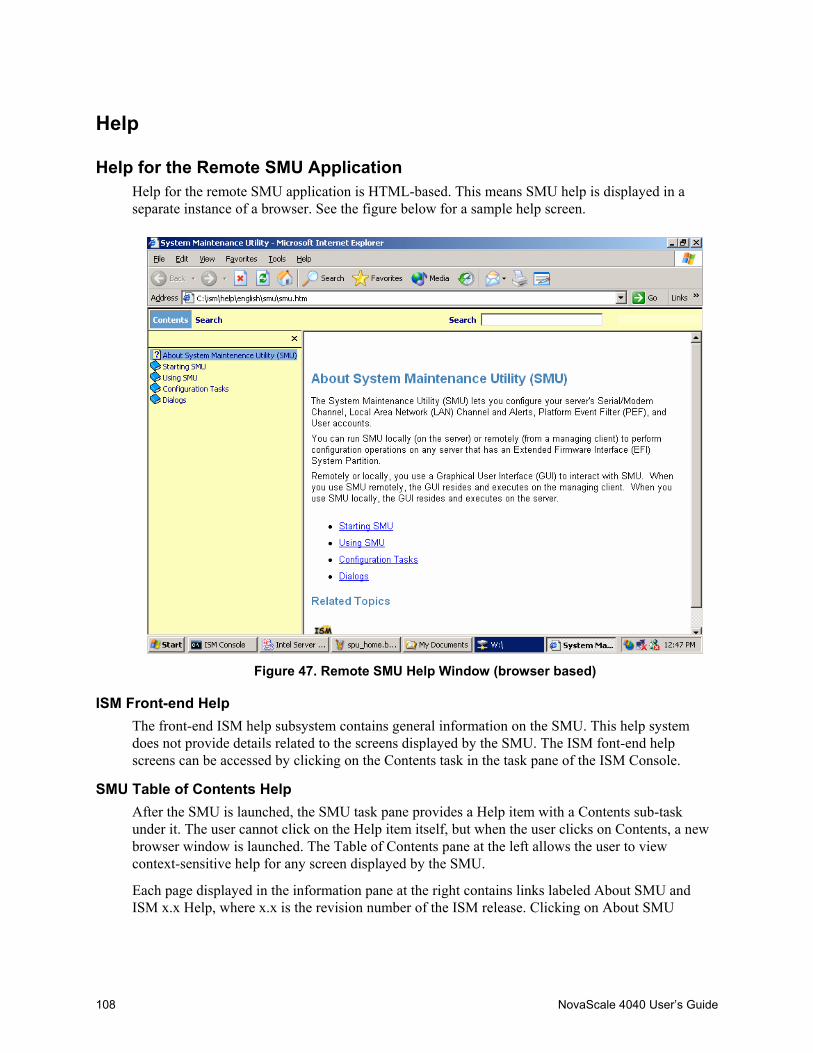
108 NovaScale 4040 User’s Guide
Help
Help for the Remote SMU ApplicationHelp for the remote SMU application is HTML-based. This means SMU help is displayed in aseparate instance of a browser. See the figure below for a sample help screen.
Figure 47. Remote SMU Help Window (browser based)
ISM Front-end HelpThe front-end ISM help subsystem contains general information on the SMU. This help systemdoes not provide details related to the screens displayed by the SMU. The ISM font-end helpscreens can be accessed by clicking on the Contents task in the task pane of the ISM Console.
SMU Table of Contents HelpAfter the SMU is launched, the SMU task pane provides a Help item with a Contents sub-taskunder it. The user cannot click on the Help item itself, but when the user clicks on Contents, a newbrowser window is launched. The Table of Contents pane at the left allows the user to viewcontext-sensitive help for any screen displayed by the SMU.
Each page displayed in the information pane at the right contains links labeled About SMU andISM x.x Help, where x.x is the revision number of the ISM release. Clicking on About SMU
Configuration Software and Utilities 109
returns the user to a general front page for the SMU (is not context-specific). Clicking on ISM x.xHelp launches a new browser that contains the front-end ISM help.
Most screens displayed by the SMU have a Help button. If no help is displayed, clicking Helplaunches a browser window that shows the context-sensitive help for the screen from which theuser clicked Help; a table of contents is not displayed. If the link for About SMU link clicked, thehelp window is repainted with a table of contents pane and the About SMU information in theinformation pane. If the ISM x.x Help link is clicked, a separate browser window is launched andthe front-end ISM help is displayed in that window.
If a help browser window was previously launched from the Contents task of the SMU application,when a Help button on an SMU screen is clicked, the information pane is replaced with thecontext-sensitive help for the screen containing the Help button.
Help for the Local SMU ApplicationHelp for the local SMU application appears in a modeless window on the client console. Thismeans that when the user wants to return to the local SMU application, click on the applicationwindow to bring it to the foreground. The <F1> can be used to toggle between the SMUapplication window and the help window. Since the application uses the entire screen and itscontainer is not re-sizeable, the help window is hidden when the application window is brought tothe front.
The help window is re-sizeable and can be moved. An example of the local help window is shownbelow.
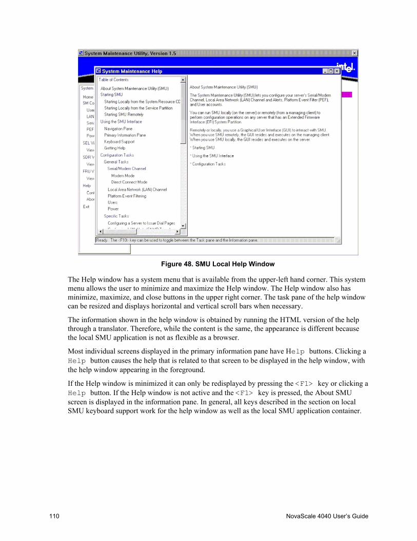
110 NovaScale 4040 User’s Guide
Figure 48. SMU Local Help Window
The Help window has a system menu that is available from the upper-left hand corner. This systemmenu allows the user to minimize and maximize the Help window. The Help window also hasminimize, maximize, and close buttons in the upper right corner. The task pane of the help windowcan be resized and displays horizontal and vertical scroll bars when necessary.
The information shown in the help window is obtained by running the HTML version of the helpthrough a translator. Therefore, while the content is the same, the appearance is different becausethe local SMU application is not as flexible as a browser.
Most individual screens displayed in the primary information pane have Help buttons. Clicking aHelp button causes the help that is related to that screen to be displayed in the help window, withthe help window appearing in the foreground.
If the Help window is minimized it can only be redisplayed by pressing the <F1> key or clicking aHelp button. If the Help window is not active and the <F1> key is pressed, the About SMUscreen is displayed in the information pane. In general, all keys described in the section on localSMU keyboard support work for the help window as well as the local SMU application container.

Configuration Software and Utilities 111
Shutting Down the ServerTo shut down the server you must exit the +-operating system (if applicable) and then use thepower button to power down the server.
Follow these steps to power down the NovaScale 4040.1. If the server is running an operating system, use its commands or GUI to logoff (if necessary)
and exit the operating system. If the operating system does not automatically power down theserver, then successfully exiting the operating system causes the following prompt to appear:Shell>
2. After this prompt appears, press and hold the power button for several seconds. Holding thepower button in powers down the server.
CAUTIONPowering down the server with the power button does not remove all powerfrom the system. The +12 V standby power is still available to the systemeven when it has been powered down. To remove standby power from thesystem you must unplug both power cords from the chassis.

112 NovaScale 4040 User’s Guide
EFI Platform Diagnostic TestsEFI Platform Diagnostic Tests allow you to quickly assess the server’s hardware status, view testlogs, and determine the server’s current configuration. You can run EFI Platform Diagnostic Testsfrom within the EFI environment. The remainder of this section explains how to run the EFIPlatform Diagnostic Tests.
Starting the ApplicationUse the following steps to setup and run tests.
✏ NOTEYou may also run this utility directly from the Resource CD. This causes theutility to run in a RAM drive which means log files are volatile and will needto be copied to write-able media if they need to be saved.
1. Boot to the EFI shell.2. Create a directory "efi\service\diagnostics" on the target drive such as a hard drive.3. Copy the distributed FieldDiags binary file (fielddiags.efi) to the root directory of the target.
drive.4. Run the following command using the distributed FieldDiags binary file (fielddiags.efi):
fielddiags -d \efi\service\diagnostics
(it unpacks and installs the FieldDiags software).5. Delete the fielddiags.efi file previously copied onto the target drive.6. Be sure your working directory is on the same drive that contains the test software, type in the
following command and press the <Enter> key to load and run the tests:\efi\service\diagnostics\fielddiags
Entering this command causes the tests to run regardless of your current working directory.You can also type a relative pathname that is based on your current working directory toexecute the tests.
In addition to running tests, you can display system configuration information or the current testlog. To do either, highlight the appropriate option and then press the <Enter> key.

Configuration Software and Utilities 113
Understanding the General User InterfaceThe platform diagnostics application uses multiple screens from which you can choose executionoptions, enable or disable tests for execution, and define test parameters. The initial screen consistsof four pull down menus:• File• System Information• Platform Test• Help
Up and down arrows navigate vertically through all areas of the screen. During navigation, itemsthat you can modify become highlighted. Left and right arrow keys navigate horizontally throughthe menus.• Pressing the <Enter> key with an execution option highlighted causes the action to occur.• Pressing the <Enter> key from within a dialog box causes data to be entered.• Pressing the <F1> key while a test is highlighted or has the greater-than character (>) to the left
of it causes on-line help for that test to appear.• Pressing the <ESC> key with on-line help displayed or with a dialog box displayed dismisses
the information or dialog box.
Understanding Basic TestingThe Platform Test menu is set up in the order that is typically used:• Test Setup allows you to determine which tests to run and how thoroughly to test.• Run Test starts test execution and provides some indication of test progress.• View Results shows the results window and allows you to view and clear the test log.
Enabling Tests For ExecutionTo enable one or more tests for execution, select Test setup from the Platform test menu. Use theup and down arrows to first select a test, and then press <Q> for a quick test, <C> for a completetest, or <D> to disable the test. When a test is enabled, the word "Quick" or “Complete” appearsnext to the test under the "Coverage" column. If a test is disabled, the word "Disabled" appearsunder that column. An individual test may be executed up to nine times for each run of the testsuite. With the test highlighted, pressing a single digit 1 – 9 on the keyboard sets the number ofiterations for an individual test.
Because of space limitations, the test area of the screen displays only six tests at a time. Using thearrow keys causes the test display to scroll completely through the list.
✏ NOTEBy default on startup all tests are set to “Quick” test and single iteration.You may go directly to “Run Test” if no changes are required.
114 NovaScale 4040 User’s Guide
Setting Test OptionsThe Test options pull down opens the Test Options window. In the Test Options window you maydetermine if the test stops on one of two parameters; time or iterations. By navigating to the “StopOn” item in the window and hitting the <Enter> key you are given the options of “Iterations” or“Minutes”. If Iterations is set, the testing stops after executing the full test suite, however manytimes is indicated by the number in the “Iterations” edit box. If minutes is selected, the test suiterepeats until the number of minutes in the Minutes edit box have passed, and then stop afterexecuting the final test of that suite.
Interpreting ResultsTest results appear next to the enabled tests in the test area of the screen. Each time a test passes orfails during a loop, the appropriate pass or fail count increments. For failed tests, Field ReplaceableUnit (FRU) information also appears under the "Details" column.
If you want greater detail for the test run, view the test log file. For information on how to view thetest log file, refer to Section “Viewing the Test Log” below.
Getting Help On Individual TestsTo display on-line help text files for a particular test, use the arrow keys to highlight the desired testand then press the <F1> key. The application presents a scrollable text file that describes thesub-tests for the highlighted test.
Viewing System InformationTo view system information, use the arrow keys to highlight the appropriate menu item, and pressthe <Enter> key. From the menu select the system information to be viewed.
After pressing the <Enter> key, the application displays a scrollable information box that containssystem information.
Configuration Software and Utilities 115
Viewing the Test LogBy default, the diagnostic software keeps the log file in "efi\service\diagnostics" in a file named"fielddiags.log."
To view this file, use the arrow keys to highlight the Platform Test menu and select View Resultsfrom that menu, by pressing the <Enter> key. After pressing the <Enter> key, the applicationdisplays a scrollable information box that contains the sessions test log. Because the log file is aUnicode file, you can also view it in the EFI shell by using the "type -u" command, and in theWindows operating system using the Notepad application.
All test results are appended to the previous log file. To clear the log file select the Clear log buttonon the View Results window. Note: because the log file is now always appended, it isrecommended that the file be cleared a regular basis to keep the file size from getting too large.
EFI Service PartitionThe EFI Service Partition provides the ability to remotely access a server running EFI, via modemor LAN, for the purpose of executing configuration/setup utilities, remote diagnostics, and anyother software designed to be compatible with this environment.
Service Partition Requirements1. The SP may reside on any of the EFI-recognized physical drives. Drives not supported by EFI
cannot be used for a service partition or EFI System Partition.2. An EFI System Partition cannot be installed on legacy MBR disks. The disk must be formatted
as a GPT disk. (GUID Partition Table). This utility will not reinitialize a legacy MBR disk.3. The SP requires at least 65 MB free on the chosen EFI System Partition.4. For proper operation, there must be only one set of service partition files present.
Installing Service Partition FilesThe service partition on an Itanium 2-based platform is part of the Extensible Firmware Interface(EFI) System Partition. This partition is not a separate, dedicated partition as is its functionalcounterpart on an IA-32 platform. The presence of “service partition” files within the existingsystem partition defines the EFI Service Partition.
The service partition is established when the installation program copies service partition files intothe existing system partition. These files comprise utilities, diagnostics, and other softwarerequired for remote management. You can run the utilities and diagnostics located on the servicepartition either locally or remotely. In order to run the utilities and diagnostics you must boot theserver from the partition. Applications that execute in the service partition run only on themanaged server.
116 NovaScale 4040 User’s Guide
Installation RequirementsBe sure you adhere to the following requirements when installing the service partition files:• The current ECO BIOS and FW are installed.• You can use the installation software on the current System Resource CD to install the system
partition files, thus defining the service partition. To get the latest version of this software,contact your Bull representative.
• At least 125 MB or one percent of the selected drive must be available (asun-partitioned space).
Installing the FilesFollow these steps to install the service partition files onto a managed server whose operatingsystem is already installed:1. Insert the System Resource CD into the managed server’s CD-ROM drive before booting to
EFI Shell. Boot the system into EFI Shell, the EFI CD Menu program launches automatically.If the EFI CD Menu program does not launch in the EFI Shell, mount and map to the CD driveand type ‘startup’ and press <Enter> to launch the EFI CD Menu.
2. From the menu tab, use the arrow keys to navigate over to the Utility menu and hit <Enter> orthe down arrow to expand the menu.
3. From the Utility menu, arrow down to “Install Service Partition” and hit <Enter> to launch theService Partition Administration menu.
4. Choose 3 and press <Enter> to install the service partition files.5. The installation software reports whether a system partition has been found. If so, it is
recommended that you choose to install the service partition files onto the existing systempartition. Do so by choosing 1 and pressing <Enter>.
6. Choose the number for the system partition on which to install the partition files and press<Enter>.
7. After receiving the message indicating that all files were installed successfully, press any key.8. Press <ESC> to exit the Service Partition Administration menu and return to the EFI CD menu.
✏ NOTEThe "Install Service Partition Command" installs:
- the Service Partition basic utilities,
- the System Maintenance Utility (SMU),
- the EFIConfig utility.
Configuration Software and Utilities 117
Booting the Server from the Service PartitionThe service partition contains utilities and diagnostics. To run these utilities or diagnostics, youneed to boot the server from the service partition. You can reboot a managed server from theservice partition one of two ways: locally, or remotely. When you reboot the server to the servicepartition remotely, you can do the following:• Run EFI shell commands on the server• Run a program from the service partition• Run diagnostics specific to the server• Run the SMU to configure the server for Server Management
LocallyFollow these steps to locally boot the server to the service partition:1. Restart the managed server.2. Monitor the boot process and press ‘F2’ to enter BIOS setup. Arrow over to the “System
Management” menu, and select “Enabled” for the “Service Boot” option. Hit the <F10> tosave the setting and exit out of the BIOS setup and the system automatically reboots to theService Partition.
Console RedirectionThe BIOS supports redirection of both video and keyboard via serial link. This section details theserial redirection scheme. For redirection over LAN (Serial over LAN or SOL), please refer to theISM Users Guide.
When console redirection is enabled, local (host server) keyboard input and video output are passedboth to the local keyboard and video connections, and to the remote console via the serial link.Keyboard inputs from both sources are considered valid and video is displayed to both outputs.Optionally, the system can be operated without a host keyboard or monitor attached to the systemand run entirely via the remote console. Setup and any other text-based utilities can be accessed viaconsole redirection. Note that serial redirection uses PC-ANSI and the UART settings assume1 stop bit.

118 NovaScale 4040 User’s Guide
OperationWhen redirecting through a modem (as opposed to a null modem cable), the modem needs to beconfigured with the following:• Auto-answer (for example, ATS0=2, to answer after two rings).• Modem reaction to DTR set to return to command state (e.g., AT&D1).
Failure to provide item #2 results in the modem either dropping the link when the server reboots (asin AT&D0) or becoming unresponsive to server baud rate changes (as in AT&D2).
The Setup/EMP option for handshaking must be set to CTS/RTS + CD for optimum performance.The CD refers to carrier detect. If EMP is sharing the COM port with serial redirection, thehandshaking must be set to CTS/RTS+ CD. In selecting this form of handshaking, the server isprevented from sending video updates to a modem that is not connected to a remote modem. If thisis not selected, video update data being sent to the modem inhibits many modems from answeringan incoming call. An EMP option utilizing CD should not be used if a modem is not used and theCD is not connected.
Once console redirection is selected via Setup, redirection binary is loaded into memory andactivated during POST. While redirection cannot be “removed” without rebooting, it can beinhibited and restarted. When inhibited, the serial port is released by redirection and might be usedby another application. Restarting reclaims the serial port and continues redirection.Inhibiting/restarting is accomplished through the following INT 16h mechanism. The standard INT16h (keyboard handler) function ah=05h places a keystroke in the key buffer, just as if an actualkey had been pressed. Keystrokes so buffered are examined by redirection, and if a valid commandstring has been sent, it is executed. The following commands are supported in this fashion:• Esc-CDZ0 - Inhibit Console Redirection• Esc-CDZ1 - Restart Console Redirection
In order to inhibit redirection, the software must call INT 16h, function ah=05h five times to placethe five keys in the key buffer. Keystrokes sent to the INT 16h buffers for purposes of invoking acommand are buffered, and should be removed via the normal INT 16h calls to prevent thesekeystrokes from being passed on to another application.
Keystroke MappingsDuring console redirection, the remote terminal (which may be a dumb terminal or a system with amodem running a communication program) sends keystrokes to the local server. The local serverpasses video back over this same link.
For keys that have an ASCII mapping, such as A and Ctrl-A, the remote simply sends the ASCIIcharacter. For keys that do not have an ASCII mapping, such as F1 and Alt-A, the remote mustsend a string of characters, as defined in the tables below. The strings are based on the ANSIterminal standard. Since the ANSI terminal standard does not define all the keys on the standard101 key U.S. keyboard, mappings for these keys were created, such as F5 - F12, Page Up, andPage Down.

Configuration Software and Utilities 119
Alt key combinations are created by sending the combination ^[} followed by the character to beAlt modified. Once this Alt key combination is sent (^[}), the next keystroke sent is translated intoits Alt-key mapping (that is, if ^[} is mapped to Shift-F1, then pressing Shift-F1 followed by ‘a’would send an Alt-a to the server).
The remote terminal can force a refresh of its video by sending ^[{.
Presently, unusual combinations outside of the ANSI mapping and not in the table below, are notsupported (for example: Ctrl-F1).
Table 22. Non-ASCII Key MappingsKey Normal Shift Ctrl AltESC ^[ NS NS NSF1 ^[OP NS NS NSF2 ^[OQ NS NS NSF3 ^[OR NS NS NSF4 ^[OS NS NS NSF5 ^[OT NS NS NSF6 ^[OU NS NS NSF7 ^[OV NS NS NSF8 ^[OW NS NS NSF9 ^[OX NS NS NSF10 ^[OY NS NS NSF11 ^[OZ NS NS NSF12 ^[O1 NS NS NSPrint Screen NS NS NS NSScroll Lock NS NS NS NSPause NS NS NS NSInsert ^[[L NS NS NSDelete (7Fh) NS NS NSHome ^[[H NS NS NSEnd ^[[K NS NS NSPg Up ^[[M NS NS NSPg Down ^[[2J NS NS NSUp Arrow ^[[A NS NS NSDown Arrow ^[[B NS NS NSRight Arrow ^[[C NS NS NSLeft Arrow ^[[D NS NS NSTab (09h) NS NS NS
NS = Not supported, (xxh) = ASCII character xx
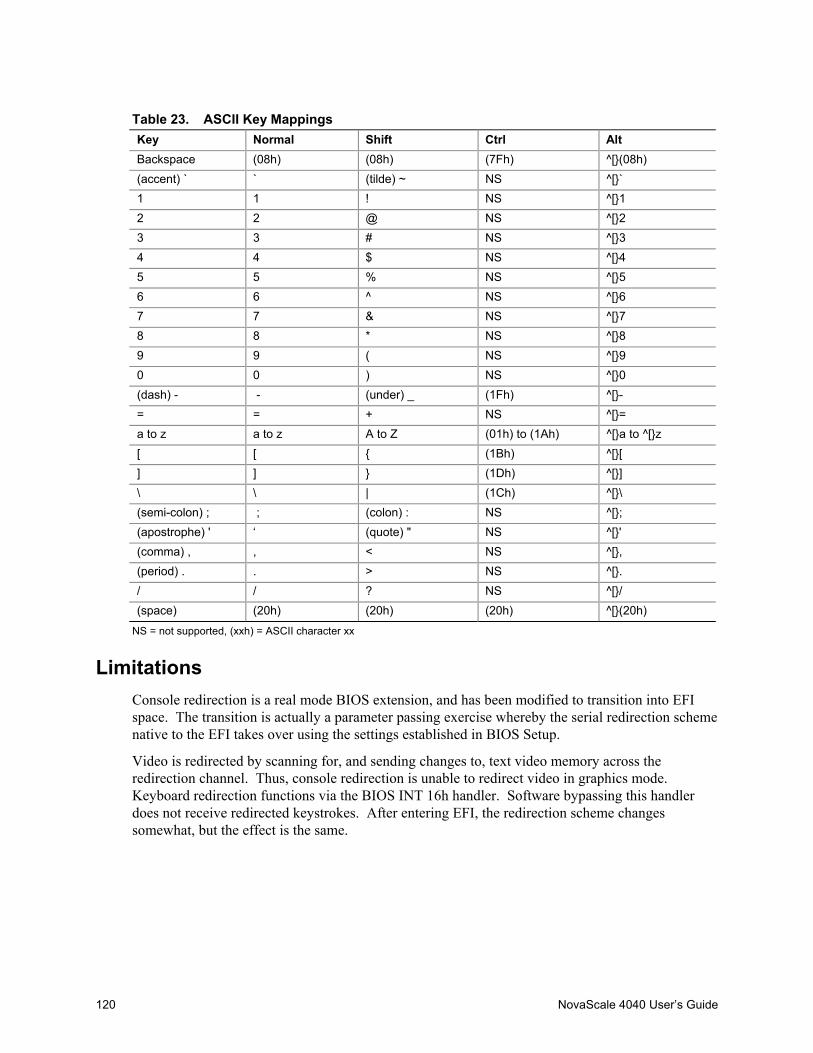
120 NovaScale 4040 User’s Guide
Table 23. ASCII Key MappingsKey Normal Shift Ctrl AltBackspace (08h) (08h) (7Fh) ^[}(08h)(accent) ` ` (tilde) ~ NS ^[}`1 1 ! NS ^[}12 2 @ NS ^[}23 3 # NS ^[}34 4 $ NS ^[}45 5 % NS ^[}56 6 ^ NS ^[}67 7 & NS ^[}78 8 * NS ^[}89 9 ( NS ^[}90 0 ) NS ^[}0(dash) - - (under) _ (1Fh) ^[}-= = + NS ^[}=a to z a to z A to Z (01h) to (1Ah) ^[}a to ^[}z[ [ { (1Bh) ^[}[] ] } (1Dh) ^[}]\ \ | (1Ch) ^[}\(semi-colon) ; ; (colon) : NS ^[};(apostrophe) ' ‘ (quote) " NS ^[}'(comma) , , < NS ^[},(period) . . > NS ^[}./ / ? NS ^[}/(space) (20h) (20h) (20h) ^[}(20h)
NS = not supported, (xxh) = ASCII character xx
LimitationsConsole redirection is a real mode BIOS extension, and has been modified to transition into EFIspace. The transition is actually a parameter passing exercise whereby the serial redirection schemenative to the EFI takes over using the settings established in BIOS Setup.
Video is redirected by scanning for, and sending changes to, text video memory across theredirection channel. Thus, console redirection is unable to redirect video in graphics mode.Keyboard redirection functions via the BIOS INT 16h handler. Software bypassing this handlerdoes not receive redirected keystrokes. After entering EFI, the redirection scheme changessomewhat, but the effect is the same.

Configuration Software and Utilities 121
Interface to Server ManagementIf BIOS determines that console redirection is enabled, reads the current baud rate from EMP, andpasses this value to the appropriate management controller via the IPMB.
Sample Setup for Console RedirectionThis is an example of how to configure the console/host and server for console redirection. In thisexample, the console is running under Windows XP with SP2. The console and server is directlyconnected through the serial ports of both systems using a serial null modem cable:
Server Configuration1. Power on the server and when prompted, press the <F2> key to enter BIOS Setup.2. The BIOS Setup menu displays the Main menu. Use the arrow keys move over to the “System
Management” menu.3. At “System Management” menu, arrow down to the “Console Redirection” submenu and press
the <Enter> key to enter this menu.4. Arrow to the “Serial Console Redirection” option and press <Enter>.5. Chose “Enabled” by using the arrow key and press <Enter>.6. The “Serial Port” menu should already have COM2 as the choice, if not, choose the “Serial
Port” option and change it by using the arrow and <Enter> as described in steps 4 and 5 for the“Serial Console Redirection” menu.
7. Set the “Baud Rate” to 115.2K.8. Set the “Flow Control” to CTS/RTS.9. Set the “Terminal Type” to VT-UTF8.10. Press the <F10> key to save the configuration changes and exit BIOS Setup.11. At the prompt to save changes and exit, select “Yes” and pressing the <Enter> key.12. This reboots the server with console redirection enabled. At this point, power down the server
and configure the console.
Console Configuration1. Boot the console into the OS.2. Launch Hyperterminal by clicking on the “Start” button in the task bar.3. Select “Programs>Accessories>Communications” and click on Hyperterminal.4. At the Connection Description window, enter “guest” for the name and click “OK” to proceed.5. At the Connect To window, select the COM port of the console that the Null modem is
connected. In this example, it is COM1.6. At the COM1 Properties window, select “115200” for the Bits per second (Baud rate) box to
match what was configured via the SMU on the server.7. Select “Hardware” for the Flow Control to match what was configured in the BIOS Setup
(CTS/RTS is the Hardware flow control).8. Leave the default settings for the other boxes. Click “OK” to accept the settings and enter the
Hyperterminal screen.9. At this point, power on the server. The console starts displaying the redirection once the video
synchronizes on the server.
122 NovaScale 4040 User’s Guide
Terminal Mode OverviewTerminal mode is a feature that allows you to directly interface to the server’s BaseboardManagement Controller (BMC) via a serial port connection and execute text-based commands.Two types of text commands are supported:• A limited selection of text commands• Standard binary IPMI 1.5 hex-ASCII commands
Using the terminal mode feature you can do the following:• Power the server on or off• Reset the server• Retrieve the server’s health status• Configure and retrieve the server management subsystems boot options• Configure and retrieve the BMC’s terminal mode configuration• Execute any platform supported binary command specified in the Intelligent Platform
Management Interface (IPMI) v1.5 specification using the hex-ASCII format
Setup and Configuration
Connection MechanismTwo types of connection mechanisms are supported as follows:• Direct connection, where a local host is connected to the target system “directly,” or from one
system’s serial port to another, and;• Modem connection, where the local host is connected to the target system via a modem.
Hardware SetupHardware setup is dependent upon the type of connection mechanism being employed as follows:• For a direct connection, a null modem cable is all that is needed to connect the local host to the
target system• For a modem connection, the local host and target systems must both be connected to modems
via serial cables
Configuration Using System Maintenance Utility (SMU)Configuration of terminal mode requires proper configuration of the following: the serial channel,user login information (user name and password), and the terminal mode configuration parameters.SMU provides methods to access and manipulate all the necessary parameters for terminal modeconfiguration.

Configuration Software and Utilities 123
Serial Channel ConfigurationThe serial channel configuration setup is done with the SMU.
Set the connection mode to the desired connection mode and the rest of the options to the desiredstate for your application.
Direct Connection ModeSet the options on the direct connection mode to the desired states for your application. It is highlyrecommended that you disable the ping message or else you will get serial ping message data fromthe BMC displayed on your terminal screen.
Modem Connection ModeSet the options on the modem connection mode to the desired states for your application. It ishighly recommended that you disable the ping message or else you will get serial ping messagedata from the BMC displayed on your terminal screen.
Be sure to save the new serial channel configuration when you are done editing the serial channelsettings
Sample Setup for Terminal ModeThis is an example of how to configure the console/host and server for Terminal Mode. In thisexample, the console is running under Windows 2000 with SP2. The console and server is directlyconnected through the serial ports of both systems using a serial null modem cable:
Server Configuration:1. Run the SMU to configure the BMC.2. In the Navigation Pane of the SMU (located on the left side), click on the Serial/Modem option.
This takes you to the Serial/Modem configuration menu.3. At the Connection Mode box, pull down the menu and select “Direct Connect Mode.”4. Select “Always Available” for the Access Mode.5. Select “Administrator” for the Privilege Level Limit.6. Select “None” for Flow Control.7. Leave the Enable Data Terminal Ready box unselected.8. Select “19200” for the Baud Rate.9. Click on the “Next” button to move to the next menu.10. Click “Next” again to get to the Terminal Mode Configuration screen.11. “Check” the Enable Terminal Mode box.12. “Check” the Enable Line Editing box.13. Select “Backspace” for the Delete Control.14. “Check” the Turn BMC echo of received characters on box.15. “Check” the Enable handshake when BMC ready to receive another message box.16. Select the “CRLF” for the Newline output sequence (BMC to console) box.17. Select the “CR” for the Newline input sequence (console to BMC) box.18. Click “Save” to save your settings and “Ok” to return to the Home page of the SMU.19. Click on the “User” option in the Navigation Pane to configure the user setup.20. Select the “Anonymous User” box and click on the “Edit” button to configure this User.

124 NovaScale 4040 User’s Guide
21. In the Edit User Configuration screen, “check” the Enable User box.22. In the Enter New Password box, enter your password. In this example the password is guest.23. Enter the password again in the Verify New Password box.24. Select “Administrator” for the User Privilege Level under the Serial/Modem Channel menu.25. Click “OK” to exit out of this menu. Click “Save” to save the configuration.26. Click “OK” at the User Save Result menu to return to the Home menu.27. At the Home menu, click on the “Exit” option in the Navigation pane to exit SMU, click “OK”
to confirm the exit.28. Reboot the server.
Console Configuration:1. Boot the console into the OS.2. Launch Hyperterminal by clicking on the “Start” button in the task bar.3. Select “Programs>Accessories>Communications” and click on Hyperterminal.4. At the Connection Description window, enter “guest” for the name and click “OK” to proceed.5. At the Connect To window, select the COM port of the console that the Null modem is
connected. In this example, it is COM1.6. At the COM1 Properties window, select “19200” for the Bits per second (Baud rate) box to
match what was configured via the SMU on the server.7. Select “None” for the Flow Control to match what was configured in the BMC.8. Leave the default settings for the other boxes. Click “OK” to accept the settings and enter the
Hyperterminal screen.9. You will now see characters being displayed to the Hyperterminal screen. This is the PING
message sent by the BMC.10. Press the <ESC> key followed by the “(“ key to enable Terminal Mode and end the PING
messages. “[TMODE OK]” is displayed.11. Type “[SYS TMODE]”, it is case sensitive and must be in uppercase. The response back will be
“[OK TMODE]” indicating that Terminal Mode is functioning.
Logging Into the Terminal Mode Session1. Remember that “guest” was the password that we set for the Anonymous User in the BMC.2. At the Hyperterminal screen enter “[SYS PWD –N guest]” to login. The “-N” represents the
Anonymous User and “guest” is the password. These are case sensitive.3. The screen returns “[SYS]” and “[OK]” to show a successful login.4. At this point, you can type any supported Terminal mode command.5. To logout type “[SYS PWD –X]”.
Configuration Software and Utilities 125
User ConfigurationA user must be configured via the SMU to make full use of terminal mode. To create a user,navigate to the SMU user configuration screen. Enter any username and password combinationsdesired. Make sure to check the box that enables a particular user for use on the serial channel. Ifthis is not done, the username will not be useable on the serial channel for terminal mode.Configure the user with the desired maximum privilege level.
Username and Password Restrictions
Spaces, left bracket characters or right bracket characters are not allowed in usernames orpasswords used with terminal mode.
Be sure to save the new user information when you are done editing the user settings!
Terminal Mode ConfigurationTerminal mode has several configuration parameters that determine behavioral characteristics ofthe terminal mode interactions with the remote console. They are outlined below and in theterminal mode configuration parameters table.See the terminal mode configuration parameters table for the BMC default settings of eachparameter.
Line Editing
When this option is enabled, it allows you to make changes to the input line before submitting it tothe BMC for processing. When line editing is enabled, it is recommended that echo be enabledas well.
Echo
When this option is enabled, the BMC echoes each character it receives to the remote console.
Handshaking
When this option is enabled, the BMC will output the following string as soon as the BMC is readyto accept another message from the remote console.Handshake string: [SYS]<newline sequence>
Delete Control Sequence
This option allows you to specify the delete control sequence for the BMC to use when the delete orbackspace key is pressed. The following delete control sequences are supported:
<DEL> - The BMC outputs a delete character<BKSP><SP>< BKSP > - The BMC outputs a backspace, space, backspace character sequenceThis delete control sequence is only valid when line editing is enabled. If line editing is notenabled, the delete key or backspace key are treated as illegal characters.
Input Newline SequenceThis option allows you to specify the input newline sequence for the BMC to expect during remoteconsole to BMC communications. The following input newline sequences are supported:
<NULL> - The NULL character (0x00)<CR> - The carriage return character
126 NovaScale 4040 User’s Guide
Output Newline Sequence
This option allows you to specify the output newline sequence for the BMC to output during BMCto remote console communications.
The following output newline sequences are supported:• <no termination sequence> - No character sequence is used to indicate output newlines• <CR-LF> - The carriage return – line feed character sequence• <NULL> - The NULL character (0x00)• <CR > - The carriage return character• <LF-CR> - The line feed – carriage return character sequence• <LF> - The line feed character
Be sure to save the new terminal mode configuration when you are done editing the terminal modesettings!
Security InformationAccess to the BMC via terminal mode is governed by the proper setup of usernames and passwordvia the SMU. A session must be established with the BMC prior to accepting any terminal modecommands. A limited selection of text commands and binary hex-ASCII commands that areassigned the lowest IPMI privilege level are available prior to session establishment with the BMC.
Since the terminal mode password is sent via clear text, it is highly desirable that the terminal modesession takes place in a secure location over a secure link, preferably via a direct connection.Connection via a modem is supported but not recommended.
Terminal Mode Commands
Input RestrictionsTerminal mode messages are bound by the restrictions listed in the following subsections.
Syntax
Terminal mode messages follow the general syntax below:[<message data>]<newline sequence>
Each terminal mode message must be preceded with the left bracket “start” character and must beended with a right bracket “stop” character and the appropriate input newline sequence.
No input characters are accepted until the start character has been received.
Terminal mode text commands are case sensitive, but hex-ASCII commands can either use upper orlower case letters for ASCII representations of hex digits.

Configuration Software and Utilities 127
Command Length
Terminal mode messages are limited to a maximum length of a 122 characters. This includes theleft and right brackets, but not control characters.
Character Support
Terminal mode messages are allowed to be composed of standard printable ASCII characters. Allother characters are treated as illegal characters.
Special Character Handling - <ESC> character
The <ESC> character can be used to delete an entire message prior to submission to the BMC forprocessing. If line editing is enabled, and the <ESC> key is followed by an input newlinesequence, the BMC responds by outputting an output newline sequence. Otherwise, the BMC goesback to looking for the start character.
Special Character Handling - <DEL> or <BKSP> character
The <BKSP> or <DEL> key can be used to delete the last character entered if the message has notbeen submitted to the BMC yet.
Special Character Handling - Line Continuation character
Long IPMI messages can be split across multiple lines by using the line continuation<BACKSLASH> character followed immediately by an input newline sequence. Line continuationcharacter usage is supported for both text and hex-ASCII commands.
Special Character Handling - Illegal characters
Any illegal characters received by the BMC clears the message in progress and forces the BMCback to looking for the start character.

128 NovaScale 4040 User’s Guide
Hex-ASCII Command FormatBinary IPMI commands are sent and received as a series of case insensitive hex-ASCII pairs, whereeach is optionally separated from the preceding pair by a single <space> character. The followingis an example of a binary IPMI request message:[18 00 22]<newline sequence>
The software ID and LUN for the remote console are fixed and implied by the command. TheSWID for messages to the remote console is always 47h, and the Logical Unit Number(LUN) is 00b.
Instead, there is a ‘bridge’ field that is used to identify whether the message should be routed to theBMC’s bridged message tracking or not. See the Terminal Mode IPMI Message Bridging sectionfor more information.
Table 24. Terminal Mode Request to BMCByte Explanation1 [7:2] – Net Function (even)
[1:0] – Responder’s LUN2 [7:2] – Requester’s Sequence Number
[1:0] – Bridge field3 Command Number4:N Data
Table 25. Terminal Mode Request from BMCByte Explanation1 [7:2] – Net Function (odd)
[1:0] – Responder’s LUN2 [7:2] – Requester’s Sequence Number
[1:0] – Bridge field3 Command Number4 Completion Code5:N Data

Configuration Software and Utilities 129
Text Command FormatText commands do not support the bridging and sequence number fields present in the hex-ASCIIcommands, are case sensitive, and are preceded by a prefix consisting of the string “SYS”.
ExamplesHex-ASCII command example (IPMI Reset Watchdog Cmd):
[18 00 22]<CR>
[1C 00 22 00]<CR-LF>
Text command example:
[SYS TMODE]<CR>
[OK TMODE]<CR-LF>
Terminal Mode IPMI Message BridgingTerminal mode supports the ability to bridge IPMI messages to another interface when binaryhex-ASCII IPMI commands are used. The message bridge is determined by the following: thebridge field, whether the message is a request or a response, the message direction with respect tothe BMC and the LUN. Table 26 lists the supported BMC combinations for IPMI messagebridging. Any other combinations are unsupported.
Note that IPMI messages to and from the system interface are transferred using the BMC SMS(System Management Software) LUN, 10b, and with the bridge field set to 00b.
Table 26. Supported BMC Combinations for IPMI Message BridgingBridgeField
Request/Response
MessageDirection (to BMC) LUN
MessageInterpretation
00b Request In 00b,01b,11b
Remote Console request to BMC functionalityMessage is a request from the remote console tothe BMC
00b Response Out 00b,01b,11b
Response to Remote Console from BMCfunctionality Message is a response to an earlierrequest from the remote console to the BMC
00b Request In 10b Remote Console request to SMS Message is arequest from the remote console to SMS via theReceive Message Queue
00b Response Out 10b SMS Response to Remote Console Message is aresponse to an earlier request from SMS
01b Response Out Any Response to earlier Bridged Request from RemoteConsole Message is the asynchronous responsefrom an earlier bridged request that wasencapsulated in a Send Message command issuedto the BMC by the remote console

130 NovaScale 4040 User’s Guide
Table 27. Terminal Mode Text CommandsCommand Switches Description
-U USERNAME<password>
Used to activate a terminal mode session. USERNAME corresponds tothe ASCII text for the username. <password> represents a printablepassword (up to 16 characters). If <password> is not provided, then aNull password (all binary 0’s) is submitted. Passwords are casesensitive.Either the SYS PWD command (or Activate Session IPMI message)must be successfully executed before any command or IPMI messagesare accepted. Note that a modem connection may be automaticallydropped if multiple bad passwords are entered.
-N <password> -N represents a Null username. <password> represents a printablepassword (up to 16 characters). If <password> is not provided, then aNull password (all binary 0’s) is submitted. Passwords are casesensitive.Either the SYS PWD command (or Activate Session IPMI message)must be successfully executed before any command or IPMI messagesare accepted. Note that a modem connection may be automaticallydropped if multiple bad passwords are entered.
SYS PWD
-X -X immediately ‘logs out’ any presently active session. Entering aninvalid password with -U or -N also has the same effect.
SYSTMODE
Used as a ‘no-op’ confirm that Terminal Mode is active. BMC returns anOK response followed by “TMODE”.
SYS SETBOOT XXYY ZZ AABB
Sets the boot flags to direct a boot to the specified device following thenext IPMI command or action initiated reset or power-on. XX…BBrepresent five hex-ASCII encoded bytes, which are the boot flagsparameter in the Boot Option Parameters. See the Boot OptionParameters Table below for more information.Upon receiving this command, the BMC automatically sets the ‘valid bit’in the boot options and sets all the Boot Initiator Acknowledge data bitsto 1b.
continued
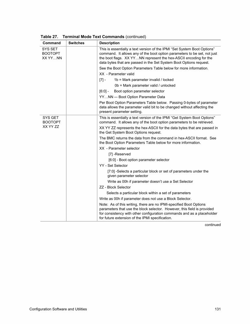
Configuration Software and Utilities 131
Table 27. Terminal Mode Text Commands (continued)Command Switches DescriptionSYS SETBOOTOPTXX YY…NN
This is essentially a text version of the IPMI “Set System Boot Options”command. It allows any of the boot option parameters to be set, not justthe boot flags. XX YY…NN represent the hex-ASCII encoding for thedata bytes that are passed in the Set System Boot Options request.See the Boot Option Parameters Table below for more information.XX - Parameter valid[7] - 1b = Mark parameter invalid / locked 0b = Mark parameter valid / unlocked[6:0] - Boot option parameter selectorYY…NN -– Boot Option Parameter DataPer Boot Option Parameters Table below. Passing 0-bytes of parameterdata allows the parameter valid bit to be changed without affecting thepresent parameter setting.
SYS GETBOOTOPTXX YY ZZ
This is essentially a text version of the IPMI “Get System Boot Options”command. It allows any of the boot option parameters to be retrieved.XX YY ZZ represents the hex-ASCII for the data bytes that are passed inthe Get System Boot Options request.The BMC returns the data from the command in hex-ASCII format. Seethe Boot Option Parameters Table below for more information.XX - Parameter selector [7] -Reserved [6:0] - Boot option parameter selectorYY - Set Selector [7:0] -Selects a particular block or set of parameters under the given parameter selector Write as 00h if parameter doesn’t use a Set SelectorZZ - Block Selector Selects a particular block within a set of parametersWrite as 00h if parameter does not use a Block Selector.Note: As of this writing, there are no IPMI-specified Boot Optionsparameters that use the block selector. However, this field is providedfor consistency with other configuration commands and as a placeholderfor future extension of the IPMI specification.
continued

132 NovaScale 4040 User’s Guide
Table 27. Terminal Mode Text Commands (continued)Command Switches Description
Returns the Terminal Mode Configuration bytes where XX and YY representhex-ASCII encoding for the volatile version of data bytes 1 and 2 as specifiedin the Terminal Mode Configuration Table below, and AA BB represent hex-ASCII encoding of the non-volatile version.V:XX YY<output termination sequence>N:AA BB<output termination sequence>
-V XX YY This command sets the volatile Terminal Mode Configuration. XX and YYrepresent hex-ASCII encoding for data bytes 1 and 2 as specified in theTerminal Mode Configuration Table below. The BMC returns the same outputas for SYS SET TCFG, above.
SYS SETTCFG
-N XX YY This command sets the non-volatile Terminal Mode Configuration. XX and YYrepresent hex-ASCII encoding for data bytes 1 and 2 as specified in theTerminal Mode Configuration Table below. The BMC returns the same outputas for SYS SET TCFG, above.
SYS RESET Directs the BMC to perform an immediate system hard reset.SYSPOWEROFF
Directs the BMC to perform an immediate system power off.
SYSPOWER ON
Causes the BMC to initiate an immediate system power on.
SYSHEALTHQUERY
Causes the BMC to return a high level version of the system health status in‘terse’ format. The BMC returns a string with the following format if thecommand is accepted.PWR:zzz H:xx T:xx V:xx PS:xx C:xx D:xx S:xx O:xxWhere:PWR is system POWER stateH is overall HealthT is TemperatureV is VoltagePS is Power Supply subsystemF is cooling subsystem (Fans)D is Hard Drive / RAID SubsystemS is physical SecurityO is Other (OEM)zzz is: “ON”, “OFF” (soft-off or mechanical off), “SLP” (sleep - used whensleep level cannot be distinguished), “S4”, “S3”, “S2”, “S1”, “??” (unknown)and xx is: ok, nc, cr, nr, uf, or ?? where:“ok” = OK (monitored parameters within normal operating ranges)“nc” = non-critical (‘warning’: hardware outside normal operating range)“cr” = critical (‘fatal’: hardware exceeding specified ratings)“nr” = non-recoverable (‘potential damage’: system hardware in jeopardy ordamaged)“uf” = unspecified fault (fault detected, but severity unspecified)“??” = status not available/unknown (typically because system poweris OFF)
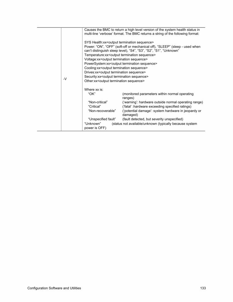
Configuration Software and Utilities 133
-V
Causes the BMC to return a high level version of the system health status inmulti-line ‘verbose’ format. The BMC returns a string of the following format:
SYS Health:xx<output termination sequence>Power: “ON”, “OFF” (soft-off or mechanical off), “SLEEP” (sleep - used whencan’t distinguish sleep level), “S4”, “S3”, “S2”, “S1”, “Unknown”Temperature:xx<output termination sequence>Voltage:xx<output termination sequence>PowerSystem:xx<output termination sequence>Cooling:xx<output termination sequence>Drives:xx<output termination sequence>Security:xx<output termination sequence>Other:xx<output termination sequence>
Where xx is:“OK” (monitored parameters within normal operating
ranges)“Non-critical” (‘warning’: hardware outside normal operating range)“Critical” (‘fatal’ :hardware exceeding specified ratings)“Non-recoverable” (‘potential damage’: system hardware in jeopardy or
damaged)“Unspecified fault” (fault detected, but severity unspecified)
“Unknown” (status not available/unknown (typically because systempower is OFF)
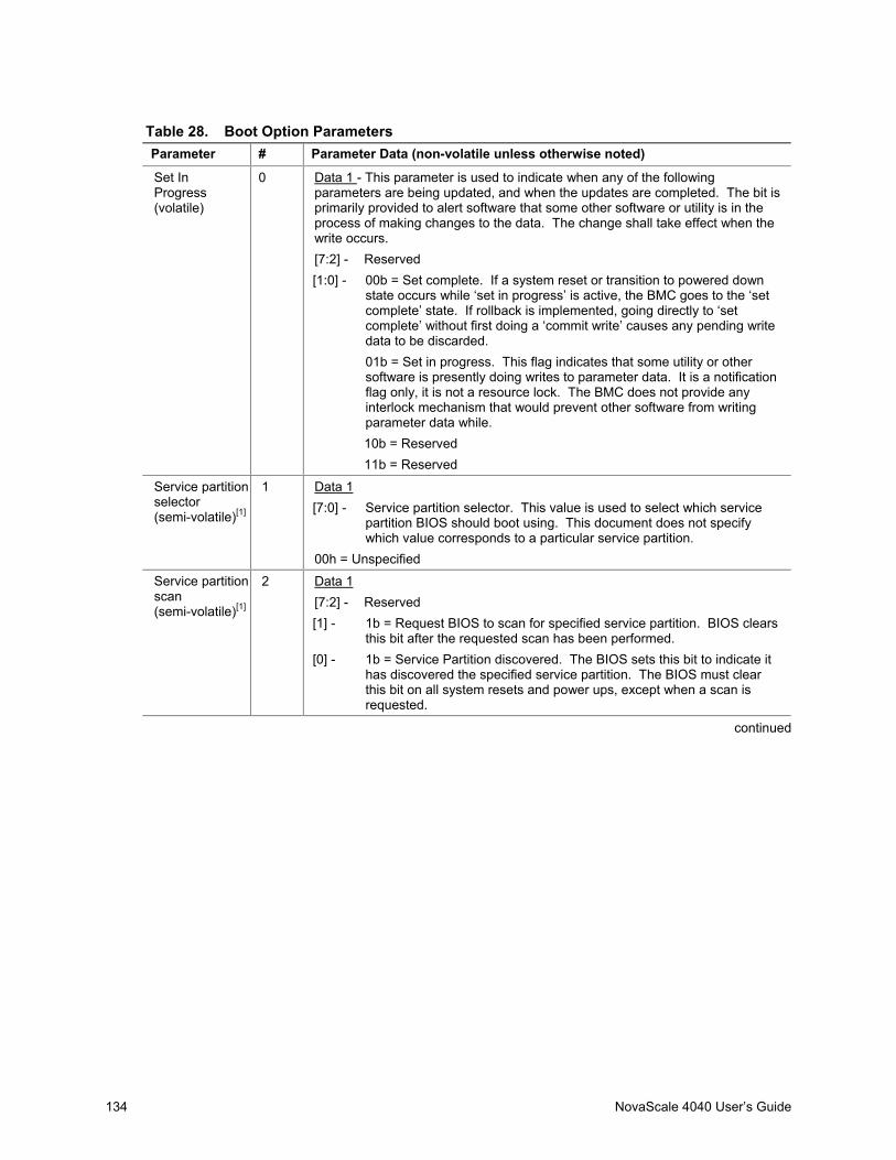
134 NovaScale 4040 User’s Guide
Table 28. Boot Option ParametersParameter # Parameter Data (non-volatile unless otherwise noted)
Set InProgress(volatile)
0 Data 1 - This parameter is used to indicate when any of the followingparameters are being updated, and when the updates are completed. The bit isprimarily provided to alert software that some other software or utility is in theprocess of making changes to the data. The change shall take effect when thewrite occurs.[7:2] - Reserved[1:0] - 00b = Set complete. If a system reset or transition to powered down
state occurs while ‘set in progress’ is active, the BMC goes to the ‘setcomplete’ state. If rollback is implemented, going directly to ‘setcomplete’ without first doing a ‘commit write’ causes any pending writedata to be discarded.01b = Set in progress. This flag indicates that some utility or othersoftware is presently doing writes to parameter data. It is a notificationflag only, it is not a resource lock. The BMC does not provide anyinterlock mechanism that would prevent other software from writingparameter data while.10b = Reserved11b = Reserved
Service partitionselector(semi-volatile)[1]
1 Data 1[7:0] - Service partition selector. This value is used to select which service
partition BIOS should boot using. This document does not specifywhich value corresponds to a particular service partition.
00h = Unspecified
Service partitionscan(semi-volatile)[1]
2 Data 1[7:2] - Reserved[1] - 1b = Request BIOS to scan for specified service partition. BIOS clears
this bit after the requested scan has been performed.[0] - 1b = Service Partition discovered. The BIOS sets this bit to indicate it
has discovered the specified service partition. The BIOS must clearthis bit on all system resets and power ups, except when a scan isrequested.
continued
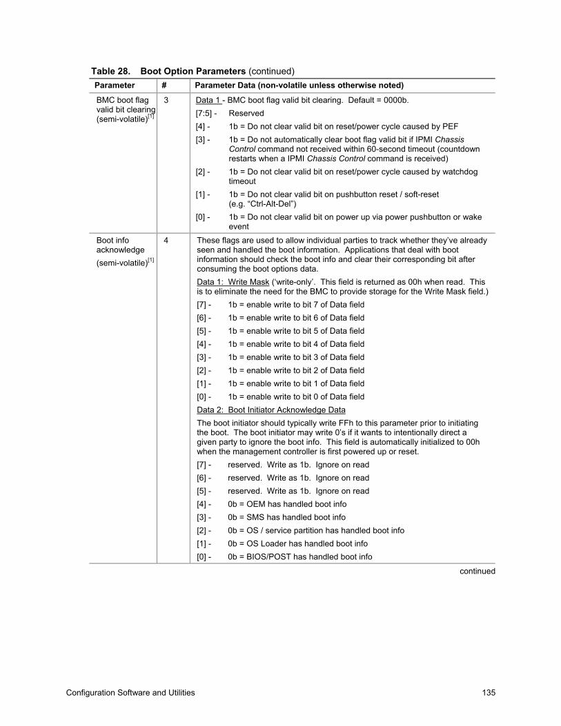
Configuration Software and Utilities 135
Table 28. Boot Option Parameters (continued)Parameter # Parameter Data (non-volatile unless otherwise noted)
BMC boot flagvalid bit clearing(semi-volatile)[1]
3 Data 1 - BMC boot flag valid bit clearing. Default = 0000b.[7:5] - Reserved[4] - 1b = Do not clear valid bit on reset/power cycle caused by PEF[3] - 1b = Do not automatically clear boot flag valid bit if IPMI Chassis
Control command not received within 60-second timeout (countdownrestarts when a IPMI Chassis Control command is received)
[2] - 1b = Do not clear valid bit on reset/power cycle caused by watchdogtimeout
[1] - 1b = Do not clear valid bit on pushbutton reset / soft-reset(e.g. “Ctrl-Alt-Del”)
[0] - 1b = Do not clear valid bit on power up via power pushbutton or wakeevent
Boot infoacknowledge(semi-volatile)[1]
4 These flags are used to allow individual parties to track whether they’ve alreadyseen and handled the boot information. Applications that deal with bootinformation should check the boot info and clear their corresponding bit afterconsuming the boot options data.Data 1: Write Mask (‘write-only’. This field is returned as 00h when read. Thisis to eliminate the need for the BMC to provide storage for the Write Mask field.)[7] - 1b = enable write to bit 7 of Data field[6] - 1b = enable write to bit 6 of Data field[5] - 1b = enable write to bit 5 of Data field[4] - 1b = enable write to bit 4 of Data field[3] - 1b = enable write to bit 3 of Data field[2] - 1b = enable write to bit 2 of Data field[1] - 1b = enable write to bit 1 of Data field[0] - 1b = enable write to bit 0 of Data fieldData 2: Boot Initiator Acknowledge DataThe boot initiator should typically write FFh to this parameter prior to initiatingthe boot. The boot initiator may write 0’s if it wants to intentionally direct agiven party to ignore the boot info. This field is automatically initialized to 00hwhen the management controller is first powered up or reset.[7] - reserved. Write as 1b. Ignore on read[6] - reserved. Write as 1b. Ignore on read[5] - reserved. Write as 1b. Ignore on read[4] - 0b = OEM has handled boot info[3] - 0b = SMS has handled boot info[2] - 0b = OS / service partition has handled boot info[1] - 0b = OS Loader has handled boot info[0] - 0b = BIOS/POST has handled boot info
continued

136 NovaScale 4040 User’s Guide
Table 28. Boot Option Parameters (continued)Parameter # Parameter Data (non-volatile unless otherwise noted)
Boot flags(semi-volatile)[1]
5 Data 1[7] - 1b = Boot flags valid. The bit should be set to indicate that valid flag
data is present. This bit may be automatically cleared based on theboot flag valid bit clearing parameter, above
[6:0] - ReservedBIOS support for the following flags is optional. If a given flag is supported, itmust cause the specified function to occur in order for the implementation to beconsidered to be conformant with this specification.The following parameters represent temporary overrides of the BIOS defaultsettings. BIOS should only use these parameters for the single boot wherethese flags were set. If the bit is 0b, BIOS should use its default configurationfor the given option.Data 2[7] - 1b = CMOS clear[6] - 1b = Lock Keyboard[5:2] - Boot device selector
0000b = No override0001b = Force PXE0010b = Force boot from default Hard-drive[2]
0011b = Force boot from default Hard-drive, request Safe Mode[2]
0100b = Force boot from default Diagnostic Partition[2]
0101b = Force boot from default CD/DVD[2]
0110b-1110b = Reserved1111b = Force boot from Floppy/primary removable media
[1] - 1b = Screen Blank[0] - 1b = Lock out Reset buttons
continued
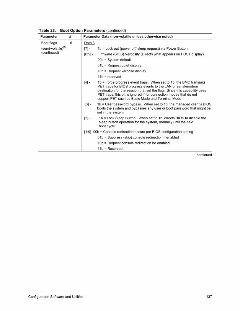
Configuration Software and Utilities 137
Table 28. Boot Option Parameters (continued)Parameter # Parameter Data (non-volatile unless otherwise noted)
Boot flags(semi-volatile)[1]
(continued)
5 Data 3[7] - 1b = Lock out (power off/ sleep request) via Power Button[6:5] - Firmware (BIOS) Verbosity (Directs what appears on POST display)
00b = System default01b = Request quiet display10b = Request verbose display11b = reserved
[4] - 1b = Force progress event traps. When set to 1b, the BMC transmitsPET traps for BIOS progress events to the LAN or serial/modemdestination for the session that set the flag. Since this capability usesPET traps, this bit is ignored if for connection modes that do notsupport PET such as Basic Mode and Terminal Mode
[3] - 1b = User password bypass. When set to 1b, the managed client’s BIOSboots the system and bypasses any user or boot password that might beset in the system
[2] - 1b = Lock Sleep Button. When set to 1b, directs BIOS to disable thesleep button operation for the system, normally until the nextboot cycle
[1:0] -00b = Console redirection occurs per BIOS configuration setting01b = Suppress (skip) console redirection if enabled10b = Request console redirection be enabled11b = Reserved
continued

138 NovaScale 4040 User’s Guide
Table 28. Boot Option Parameters (continued)Parameter # Parameter Data (non-volatile unless otherwise noted)
Boot flags(semi-volatile)[1]
(continued)
5 Data 4[7:4] - Reserved[3] - BIOS Shared Mode OverrideCan be used to request BIOS to temporarily place the channel into Sharedaccess mode.Per the recommendations in the IPMI specification, ‘Shared’ access wouldcause the baseboard serial controller to both remain enabled after POST/startof OS boot, while also allowing the BMC to be accessible. This can be usefulwhen booting to an alternative device such as a Diagnostic Partition since itmeans the partition can use the serial port but that communication with theBMC can remain available if the partition software fails.
1b = Request BIOS to temporarily set the access mode for the channelspecified in parameter #6 to ‘Shared’. This is typically accomplished bysending a ‘Set Channel Access’ command to set the volatile accessmode setting in the BMC
0b = No request to BIOS to change present access mode setting[2:0] - BIOS Mux Control OverrideCan be used to request BIOS to force a particular setting of the serial/modemmux at the conclusion of POST / start of OS boot. This override takesprecedence over the mux settings for the access mode even if the BIOSShared Mode Override is set.000b = BIOS uses recommended setting of the mux at the end of POST (See
IPMI specification for more info)001b = Requests BIOS to force mux to BMC at conclusion of POST/start of
OS-boot. If honored, this overrides the recommended setting of themux at the end of POST (See IPMI specification for more info)
010b = Requests BIOS to force mux to system at conclusion of POST/start ofOS-boot. If honored, this overrides the recommended setting of themux at the end of POST. (See IPMI specification for more info)
Data 5 - Reserved
continued
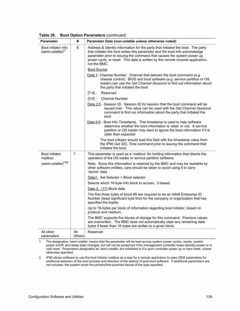
Configuration Software and Utilities 139
Table 28. Boot Option Parameters (continued)Parameter # Parameter Data (non-volatile unless otherwise noted)
Boot initiator info(semi-volatile)[1]
6 Address & Identity information for the party that initiated the boot. The partythat initiates the boot writes this parameter and the boot info acknowledgeparameter prior to issuing the command that causes the system power up,power cycle, or reset. This data is written by the remote console application,not the BMC.Boot SourceData 1- Channel Number. Channel that delivers the boot command (e.g.
chassis control). BIOS and boot software (e.g. service partition or OSloader) can use the Get Channel Sessions to find out information aboutthe party that initiated the boot
[7:4] - Reserved[3:0] - Channel NumberData 2:5 - Session ID. Session ID for session that the boot command will be
issued over. This value can be used with the Get Channel Sessionscommand to find out information about the party that initiated theboot
Data 6:9 - Boot Info Timestamp. This timestamp is used to help softwaredetermine whether the boot information is ‘stale’ or not. A servicepartition or OS loader may elect to ignore the boot information if it isolder than expected
The boot initiator should load this field with the timestamp value fromthe IPMI Get SEL Time command prior to issuing the command thatinitiates the boot.
Boot initiatormailbox(semi-volatile)[1][2]
7 This parameter is used as a ‘mailbox’ for holding information that directs theoperation of the OS loader or service partition software.Note: Since this information is retained by the BMC and may be readable byother software entities, care should be taken to avoid using it to carry‘secret’ data.Data1: Set Selector = Block selectorSelects which 16-byte info block to access. 0-based.Data 2: (17) Block dataThe first three bytes of block #0 are required to be an IANA Enterprise IDNumber (least significant byte first) for the company or organization that hasspecified the loader.Up to 16-bytes per block of information regarding boot initiator, based onprotocol and medium.The BMC supports five blocks of storage for this command. Previous valuesare overwritten. The BMC does not automatically clear any remaining databytes if fewer than 16 bytes are written to a given block.
All otherparameters
AllOthers
Reserved
1. The designation ‘semi-volatile’ means that the parameter will be kept across system power cycles, resets, systempower on/off, and sleep state changes, but will not be preserved if the management controller loses standby power or iscold reset. Parameters designated as ‘semi-volatile’ are initialized to 0’s upon controller power up or hard reset, unlessotherwise specified.
2. IPMI allows software to use the boot initiator mailbox as a way for a remote application to pass OEM parameters foradditional selection of the boot process and direction of the startup of post-boot software. If additional parameters arenot included, the system boots the primary/first-scanned device of the type specified.
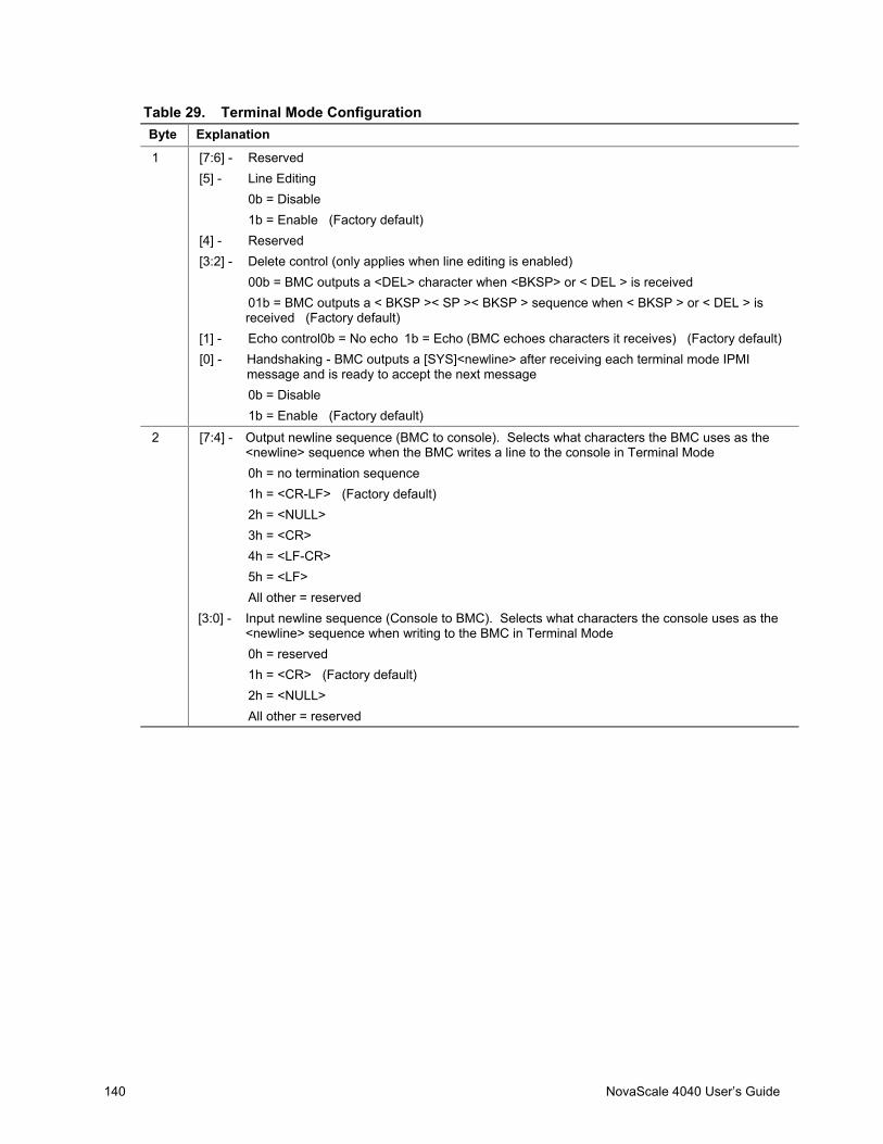
140 NovaScale 4040 User’s Guide
Table 29. Terminal Mode ConfigurationByte Explanation
1 [7:6] - Reserved[5] - Line Editing
0b = Disable1b = Enable (Factory default)
[4] - Reserved[3:2] - Delete control (only applies when line editing is enabled)
00b = BMC outputs a <DEL> character when <BKSP> or < DEL > is received01b = BMC outputs a < BKSP >< SP >< BKSP > sequence when < BKSP > or < DEL > isreceived (Factory default)
[1] - Echo control0b = No echo 1b = Echo (BMC echoes characters it receives) (Factory default)[0] - Handshaking - BMC outputs a [SYS]<newline> after receiving each terminal mode IPMI
message and is ready to accept the next message0b = Disable1b = Enable (Factory default)
2 [7:4] - Output newline sequence (BMC to console). Selects what characters the BMC uses as the<newline> sequence when the BMC writes a line to the console in Terminal Mode0h = no termination sequence1h = <CR-LF> (Factory default)2h = <NULL>3h = <CR>4h = <LF-CR>5h = <LF>All other = reserved
[3:0] - Input newline sequence (Console to BMC). Selects what characters the console uses as the<newline> sequence when writing to the BMC in Terminal Mode0h = reserved1h = <CR> (Factory default)2h = <NULL>All other = reserved

Hot Swapping System Components 141
4 Hot-swapping System Components
Tools and Supplies Needed• Pen or pencil• Antistatic wrist strap (recommended)
Equipment LogTo record the model and serial numbers of the server, all installed options, and any other pertinentinformation about the server, see Appendix A, “Equipment Log and Configuration Worksheet”.
Hot-swapping System FansThe four 120-mm cooling fans are mounted in pairs below the back top cover of the chassis. Youcan remove and install these fans without turning the server system power off. Each fan uses anamber LED to indicate the failed fan. When an LED lights, you need to replace the fan.
WARNINGMake sure that the rack is anchored securely so it will not tilt forwardwhen the server chassis is extended. A crush hazard exists should therack tilt forward which could cause serious injury.
CAUTIONDo not leave the back top cover open or a system fan removed for longerthan two minutes; system cooling is reduced.
1. If the chassis is rack-mounted, slide the chassis out far enough to expose the back top cover(see warning above).
2. Unlatch the back top cover by pressing the latches (A in Figure 49) and sliding the cover (B inFigure 49).
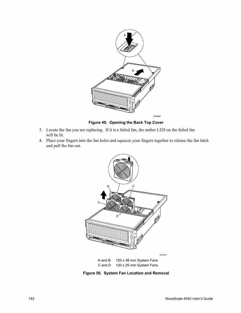
142 NovaScale 4040 User’s Guide
Figure 49. Opening the Back Top Cover
3. Locate the fan you are replacing. If it is a failed fan, the amber LED on the failed fanwill be lit.
4. Place your fingers into the fan holes and squeeze your fingers together to release the fan latchand pull the fan out.
A and B 120 x 38 mm System FansC and D 120 x 25 mm System Fans
Figure 50. System Fan Location and Removal

Hot Swapping System Components 143
Hot-swapping Hard Disk DrivesThe procedures in this section describe how to determine drive status, remove a faulty drive, andinstall a new drive.
Determining Drive StatusThe carriers contain light-pipes that allow dual color LED indicators to show through the bezel todisplay hard disk drive status as described in Table 30.
Table 30. SCSI Drive Status LED DescriptionsFeature DescriptionGreen, flashing Indicates the hard drive is activeYellow/Green flashing Indicates a hard drive fault status and hard drive is activeYellow/Blank flashing Indicates a hard drive fault statusNot illuminated Hard drive is powered
Removing a Hard Disk Drive1. Examine the amber LEDs above the Hard Drive Bays to determine which drive has failed. See
Table 30 for information on how to interpret the LEDs.2. Pull the drive carrier latch open and use the handle to pull the drive assembly toward you as
shown by the arrows in Figure 51.3. Slide the assembly out of the bay and place it on a clean, static-free work surface.
Figure 51. Removing a Hard Disk Drive

144 NovaScale 4040 User’s Guide
Installing a Hard Disk Drive1. With the drive carrier handle open fully, place the drive carrier in the peripheral drive bay and
slide the drive carrier all the way into the drive bay.2. Using the drive carrier handle, firmly push the assembly into the bay until the drive docks with
the SCSI backplane connector.3. Swing the drive carrier handle closed until it latches.
Hot-swapping Power Supplies
CAUTIONBecause of chassis airflow disruption, a power supply bay should never bevacant (without a power supply or a filler panel) for more than five minuteswhen the server power is on. Exceeding five-minutes might cause the systemto exceed the maximum acceptable temperature and possibly damage systemcomponents.
In a fully configured system (see Figure 52), the power system contains two 1200-watt auto rangingpower supplies. If you have only one power supply installed, it must occupy power supply bayA and a filler panel must be installed in power supply bay B. For 120 VAC input, two power
supply modules must be installed for normal operation.
Figure 52. Power Supply Installation Order

Hot Swapping System Components 145
Determining Power Supply StatusEach power supply has three LEDs that indicate whether power is supplied to the power supply andthe health of the power supply. Table 31 provides more detail on the three LEDs. For location ofthe LEDs, see Figure 2 on page 9.
Table 31. Power Supply LEDsPWR(Power)Green LED
PFAIL(Predictive Failure)Amber LED
FAIL(Power Supply Failure)Amber LED Description
Off
Off
Off
No AC power to any power supplies
Off
Off
On
No AC power to a specific powersupply or power supply failure
Blinking
Off
Off
AC present / Standby output on
On
Off
Off
DC outputs on and okay
On
Off
Blinking
Current limit
On
Blinking
Off
Predictive failure

146 NovaScale 4040 User’s Guide
Removing a Power Supply
CAUTIONAny unused power supply slots must be covered with a filler panel.Uncovered slots can disrupt the airflow used for cooling the system.
1. Locate the power supply you want to remove.2. Push the thumb latch (A in Figure 53) to unlock the power supply handle and pull the handle
(in direction B in Figure 53) to undock the supply.3. Pull the power supply out of the chassis and set the power supply aside.
Figure 53. Removing a Power Supply

Hot Swapping System Components 147
Installing a Power Supply1. Remove the new power supply from the protective packaging, and place it on a clean
ESD-protected work surface.2. Record the model and serial numbers of the power supply in your equipment log. See
Appendix A for the equipment log.3. Remove the filler panel from the back panel of the chassis if installed.4. Slide the replacement power supply partway into the power supply bay (A in Figure 54).5. Verify that the locking handle (B in Figure 54) is open.6. With the handle in the open position, slide power supply into the power supply bay until
it stops.7. As shown by arrow B in Figure 54, rotate the handle to lock the power supply into place.8. Check the new power supply’s LEDs to verify proper power supply function.
Figure 54. Installing a Power Supply

148 NovaScale 4040 User’s Guide
Hot Plugging PCI Add-in CardsBefore replacing a hot-plug PCI I/O card without shutting down the server, use the operatingsystem or a resident GUI to shut down or power off the PCI I/O slot you are working on. Verifythat the green power LED for the slot is off before replacing the card.
CAUTIONThe I/O bay should not be extracted from the chassis to hot-plug PCI cards.Instead, slide the back top cover open to gain access.
Removing Hot-plug PCI Add-in Cards
WARNINGMake sure that the rack is anchored securely so it won’t tilt forwardwhen the server chassis is extended. A crush hazard exists should therack tilt forward which could cause serious injury.
CAUTIONExpansion slot covers must be installed on all vacant slots to maintain theelectromagnetic emission characteristics of the server and to ensure propercooling of the system.
1. If your server is operating, use your operating system or GUI application to power down thePCI slot that contains the board you are going to remove. NOTE: the Attention switch on theback of the chassis will not be supported until a Post Platform Release BIOS. Please check theBIOS release notes of the BIOS installed on the system to verify whether using the Attentionbutton to initiate the slot power down is supported.
2. The green power LED blinks and turns OFF.3. If the system is mounted in a rack, pull the chassis out of the rack as far as it’ll go.4. Open the back top cover by pressing the latches (A in Figure 49) and sliding the cover (B in
Figure 49)to expose the hot-plug PCI slots.5. Verify the green power LED for the slot you are working with is turned off.6. Disconnect any cables attached to the board you are removing.
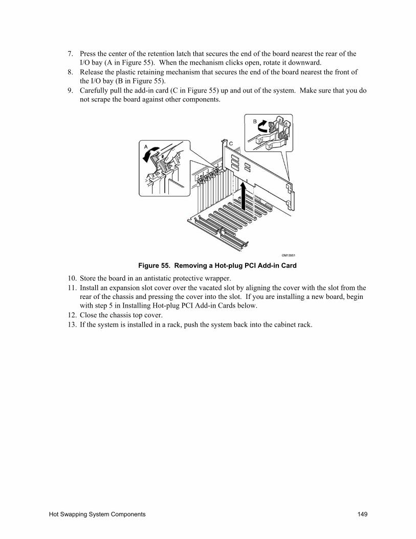
Hot Swapping System Components 149
7. Press the center of the retention latch that secures the end of the board nearest the rear of theI/O bay (A in Figure 55). When the mechanism clicks open, rotate it downward.
8. Release the plastic retaining mechanism that secures the end of the board nearest the front ofthe I/O bay (B in Figure 55).
9. Carefully pull the add-in card (C in Figure 55) up and out of the system. Make sure that you donot scrape the board against other components.
Figure 55. Removing a Hot-plug PCI Add-in Card
10. Store the board in an antistatic protective wrapper.11. Install an expansion slot cover over the vacated slot by aligning the cover with the slot from the
rear of the chassis and pressing the cover into the slot. If you are installing a new board, beginwith step 5 in Installing Hot-plug PCI Add-in Cards below.
12. Close the chassis top cover.13. If the system is installed in a rack, push the system back into the cabinet rack.

150 NovaScale 4040 User’s Guide
Installing Hot-plug PCI Add-in Cards1. If your server is operating, use your operating system or GUI application to make sure the PCI
slot that you are installing the board into is powered down.2. If the system is mounted in a rack, pull the chassis out of the rack as far as it’ll go.
WARNINGMake sure that the rack is anchored securely so it will not tilt forwardwhen the server chassis is extended. A crush hazard exists should therack tilt forward which could cause serious injury.
3. Open the back top cover by pressing the latches (A in Figure 49) and sliding the cover (B inFigure 49).to expose the hot-plug PCI slots.
4. Being careful not to touch the components or gold edge connectors on the add-in board, removeit from its protective wrapper, and place it on a clean ESD-protected work surface.
5. Record in your log the serial number of the board and any jumpers or switch settings accordingto the board manufacturer’s instructions. See Appendix A for the equipment log.
6. Be sure that the plastic latches that secure the ends of the board (A and D in Figure 56) areopen so that they will allow the add-in board to be inserted.
✏ NOTEEach PCI slot has four indicator LEDs: two on the outside and two on theinside of the system. The LEDs operate differently depending upon theoperating system installed. Please refer to your operating system’s manual.
7. If necessary, remove the expansion slot cover in the slot you’re using by pushing it out frominside the chassis.
8. Align and press the add-in board down firmly until it seats in its slot.
CAUTIONSome accessory/option board outputs exceed Class 2 or limited power sourcelimits and must use appropriate interconnecting cabling in accordance withthe national electrical code during installation.
9. Rotate the retention latch (C in Figure 56) until it clicks into place. This position both securesthe end of the board and allows it to be activated with the operating system or GUI application.
10. If the board is long enough to reach the front of the module. Ensure that it is in the slide, andthat the securing latch is closed (D in Figure 56).
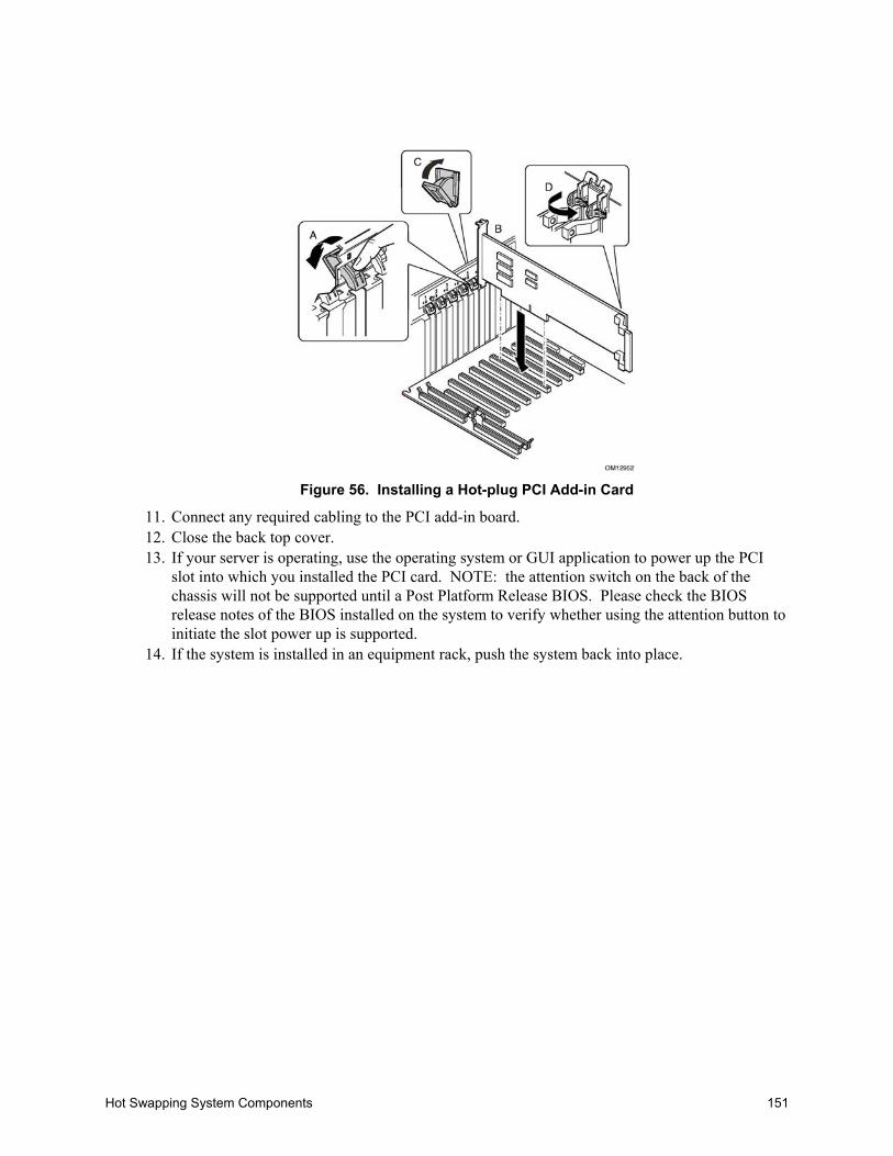
Hot Swapping System Components 151
Figure 56. Installing a Hot-plug PCI Add-in Card
11. Connect any required cabling to the PCI add-in board.12. Close the back top cover.13. If your server is operating, use the operating system or GUI application to power up the PCI
slot into which you installed the PCI card. NOTE: the attention switch on the back of thechassis will not be supported until a Post Platform Release BIOS. Please check the BIOSrelease notes of the BIOS installed on the system to verify whether using the attention button toinitiate the slot power up is supported.
14. If the system is installed in an equipment rack, push the system back into place.

152 NovaScale 4040 User’s Guide

Equipment Log and Configuration Worksheet 153
A Equipment Log and Configuration Worksheet
Equipment LogUse the blank equipment log provided here to record information about your system. You willneed some of this information when you run BIOS Setup.
Table 32. Equipment LogItem Manufacturer Name and Model Number Serial Number Date InstalledSystem
I/O Board
Processor Board
Memory Board (1)
Memory Board (2)
Midplane Board
Power Distribution Board
Hot-plug Interface Board
Front Panel Board
Processor Speed andCacheVideo Display
USB Keyboard
USB Mouse
LS-240 Drive
DVD/CD-ROM Drive
Hard Disk Drive (0)
continued

154 NovaScale 4040 User’s Guide
Table 32. Equipment Log (continued)Item Manufacturer Name and Model Number Serial Number Date InstalledHard Disk Drive (1)
Hard Disk Drive (2)
First Power Supply
Second Power Supply
Hot-plug PCI Slot (1)
Hot-plug PCI Slot (2)
Hot-plug PCI Slot (3)
Hot-plug PCI Slot (4)
Hot-plug PCI Slot (5)
Hot-plug PCI Slot (6)
Hot-plug PCI Slot (7)
Hot-plug PCI Slot (8)
I/O Board5 V DC-to-DCConverter (1)I/O Board5 V DC-to-DCConverter (2)I/O Board2.5/3.3 V DC-to-DCConverters (1)I/O Board2.5/3.3 V DC-to-DCConverters (2)Processor Board (Pri.)2.5/3.3 V DC-DCConverterProcessor Board (Sec.)2.5/3.3 V DC-DCConverters (1)Processor Board (Sec.)2.5/3.3 V DC-DCConverters (2)

Warnings 155
B Warnings
Warning: English (USA)
AVERTISSEMENTS : Français
WARNUNG: Deutsch
AVVERTENZA: Italiano
ADVERTENCIA: Español

156 NovaScale 4040 User’s Guide
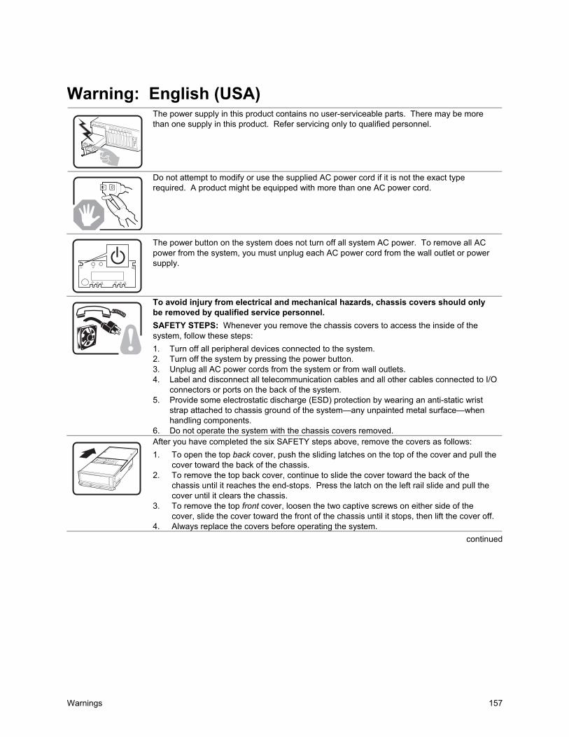
Warnings 157
Warning: English (USA)The power supply in this product contains no user-serviceable parts. There may be morethan one supply in this product. Refer servicing only to qualified personnel.
Do not attempt to modify or use the supplied AC power cord if it is not the exact typerequired. A product might be equipped with more than one AC power cord.
The power button on the system does not turn off all system AC power. To remove all ACpower from the system, you must unplug each AC power cord from the wall outlet or powersupply.
To avoid injury from electrical and mechanical hazards, chassis covers should onlybe removed by qualified service personnel.SAFETY STEPS: Whenever you remove the chassis covers to access the inside of thesystem, follow these steps:1. Turn off all peripheral devices connected to the system.2. Turn off the system by pressing the power button.3. Unplug all AC power cords from the system or from wall outlets.4. Label and disconnect all telecommunication cables and all other cables connected to I/O
connectors or ports on the back of the system.5. Provide some electrostatic discharge (ESD) protection by wearing an anti-static wrist
strap attached to chassis ground of the system—any unpainted metal surface—whenhandling components.
6. Do not operate the system with the chassis covers removed. After you have completed the six SAFETY steps above, remove the covers as follows:
1. To open the top back cover, push the sliding latches on the top of the cover and pull thecover toward the back of the chassis.
2. To remove the top back cover, continue to slide the cover toward the back of thechassis until it reaches the end-stops. Press the latch on the left rail slide and pull thecover until it clears the chassis.
3. To remove the top front cover, loosen the two captive screws on either side of thecover, slide the cover toward the front of the chassis until it stops, then lift the cover off.
4. Always replace the covers before operating the system.continued
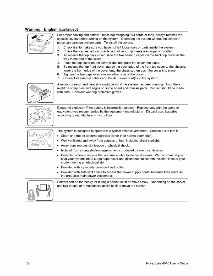
158 NovaScale 4040 User’s Guide
Warning: English (continued)
For proper cooling and airflow, unless hot swapping PCI cards or fans, always reinstall thechassis covers before turning on the system. Operating the system without the covers inplace can damage system parts. To install the covers:1. Check first to make sure you have not left loose tools or parts inside the system.2. Check that cables, add-in boards, and other components are properly installed.3. To replace the top back cover, slide the two bearing cages on the back top cover all the
way to the end of the slides.4. Place the top cover on the cover slides and push the cover into place.5. To replace the top front cover, attach the back edge of the front top cover to the chassis,
lower the front edge of the cover onto the chassis, then push the cover into place.6. Tighten the two captive screws on either side of the cover.7. Connect all external cables and the AC power cord(s) to the system.
A microprocessor and heat sink might be hot if the system has been running. Also, theremight be sharp pins and edges on some board and chassis parts. Contact should be madewith care. Consider wearing protective gloves.
Danger of explosion if the battery is incorrectly replaced. Replace only with the same orequivalent type recommended by the equipment manufacturer. Discard used batteriesaccording to manufacturer’s instructions.
The system is designed to operate in a typical office environment. Choose a site that is:• Clean and free of airborne particles (other than normal room dust).• Well-ventilated and away from sources of heat including direct sunlight.• Away from sources of vibration or physical shock.• Isolated from strong electromagnetic fields produced by electrical devices.• Protected when in regions that are susceptible to electrical storms. We recommend you
plug your system into a surge suppresser and disconnect telecommunication lines to yourmodem during an electrical storm.
• Provided with a properly grounded wall outlet.• Provided with sufficient space to access the power supply cords, because they serve as
the product’s main power disconnect.
Servers can be too heavy for a single person to lift or move safely. Depending on the server,use two people or a mechanical assist to lift or move the server.
Warnings 159
AVERTISSEMENTS : Français
Le bloc d'alimentation de ce produit ne contient aucune pièce pouvant être réparée parl'utilisateur. Ce produit peut contenir plusieurs blocs d'alimentation. Veuillez contacter untechnicien qualifié en cas de problème.
Ne pas essayer d'utiliser ni de modifier le câble d'alimentation CA fourni, s'il ne correspondpas exactement au type requis. Un produit peut être équipé de plus d'un câble d'alimentationCA.
Le bouton d'alimentation du système n'éteint pas toutes les alimentations CA du système.Pour mettre complètement le système hors tension, vous devez débrancher chaque cordond'alimentation CA de sa prise.
Pour éviter toute lésion à la suite de risques électriques et mécaniques, les panneauxdu châssis ne doivent être démontés que par un personnel qualifié.CONSIGNES DE SÉCURITÉ : Lorsque vous retirez les panneaux du châssis pour accéderà l'intérieur du système, suivez les étapes ci-dessous :1. Mettez hors tension tous les périphériques connectés au système.2. Mettez hors tension le système en appuyant sur le bouton d'alimentation.3. Débranchez tous les cordons d'alimentation CA du système ou des prises murales.4. Identifiez et déconnectez tous les câbles de télécommunications et tous les autres
câbles reliés aux connecteurs E/S ou aux ports derrière le système.5. Pour prévenir les décharges électrostatiques lorsque vous touchez aux composants,
portez un bracelet antistatique et reliez-le à la masse du système (toute surfacemétallique non peinte du boîtier).
6. Ne faites pas fonctionner le système si les panneaux du châssis sont enlevés.
Une fois que vous avez effectué les six étapes de SÉCURITÉ, retirez les panneaux commeindiqué ci-dessous :
1. Pour ouvrir le panneau arrière supérieur, poussez sur les loquets coulissants placéssur le dessus du panneau et tirez ce dernier vers l'arrière du châssis.
2. Pour retirer le panneau arrière supérieur, continuez à le faire glisser vers l'arrière duchâssis, jusqu'à ce qu'il atteigne les butées. Appuyez sur le loquet du rail gauche etretirez le panneau du châssis.
3. Pour retirer le panneau avant supérieur, desserrez les deux vis imperdables de chaquecôté du panneau, faites glisser ce dernier vers l'avant du châssis au maximum, puissoulevez-le.
4. Remettez toujours le panneau en place avant de lancer le système.
suite
160 NovaScale 4040 User’s Guide
Avertissements : Français (suite)
Pour un refroidissement et une circulation d'air efficaces, remettez toujours en place lepanneau avant d'utiliser le système, sauf si vous disposez de cartes PCI ou de ventilateurséchangeables à chaud. Le fonctionnement du système sans les panneaux risqued'endommager ses composants. Pour installer les panneaux :7. Assurez-vous en premier lieu de ne pas avoir oublié d'outils ou de composants à
l'intérieur du système.8. Vérifiez que les câbles, les cartes additionnelles et autres composants sont
correctement installés.9. Pour remettre en place le panneau supérieur arrière, faites glisser les cages à
roulement du panneau jusqu'au bout des glissières.10. Placez le panneau supérieur sur les glissières puis faites-le glisser jusqu'à la position
fermée.11. Pour remettre en place le panneau avant supérieur, accrochez la partie arrière du
panneau sur le châssis, faites basculer ce dernier vers l'avant vers le châssis, puispoussez pour le bloquer en position fermée.
12. Serrez les deux vis imperdables de chaque côté du panneau.13. Connectez tous les câbles externes et le ou les cordons d'alimentation au système.
Le microprocesseur et le dissipateur de chaleur peuvent être chauds si le système a étésous tension. Faites également attention aux broches aiguës des cartes et aux bordstranchants du capot. Les contacts doivent être établis avec soin. L'usage de gants deprotection est conseillé.
Danger d'explosion si la batterie n'est pas remontée correctement. Remplacer uniquementpar une pile du même type ou de type équivalent recommandé par le fabricant.Débarrassez-vous des piles usagées conformément aux instructions du fabricant.
Le système a été conçu pour fonctionner dans un cadre de travail normal. L'emplacementchoisi doit être :• Propre et dépourvu de poussières en suspension (sauf la poussière normale).• Bien aéré et loin des sources de chaleur, y compris du soleil direct.• À l'abri des chocs et des sources de vibration.• Isolé des forts champs électromagnétiques générés par des appareils électriques.• Protégé s'il se trouve dans des régions sujettes aux orages magnétiques. Nous vous
recommandons de connecter votre système à un suppresseur de surtension et dedéconnecter les lignes de télécommunications de votre modem pendant un oragemagnétique.
• Muni d'une prise murale correctement mise à la terre.• Suffisamment spacieux pour vous permettre d'accéder aux câbles d'alimentation (ceux-ci
étant le seul moyen de mettre le système hors tension).
Il se peut que les serveurs soient trop lourds pour qu'une seule personne puisse les souleveret les déplacer en toute sécurité. En fonction du serveur, utilisez deux personnes ou utilisezun équipement mécanique auxiliaire pour soulever ou déplacer le serveur.
Warnings 161
WARNUNG: Deutsch
Das Netzteil dieses Computers enthält keine wartungsbedürftigen Teile. Dieses Produktkann über mehrere Netzteile verfügen. Überlassen Sie Wartungsarbeiten nur qualifiziertenFachleuten.
Versuchen Sie nicht, das mitgelieferte Netzkabel zu verändern oder einzusetzen, wenn esnicht exakt dem benötigten Kabeltyp entspricht. Das Produkt kann über mehrere Netzkabelverfügen.
Durch Ausschalten des Netzschalters wird die Wechselstromversorgung des Systemsnicht unterbrochen. Um das System vom Netz zu trennen, müssen Sie das Netzkabelaus der Steckdose oder vom Netzteil abziehen.
Vermeiden Sie Verletzungen aufgrund elektrischer oder mechanischer Gefahren;lassen Sie daher den Gehäusedeckel nur von technisch qualifiziertem Personalabnehmen.SICHERHEITSHINWEISE: Beachten Sie beim Abnehmen der Gehäuseabdeckung undArbeiten im Inneren des Systems folgende Schritte:
1. Schalten Sie alle am System angeschlossenen Peripheriegeräte ab.Drücken Sie denNetzschalter, um das System abzuschalten.
2. Ziehen Sie alle Wechselstromkabel vom System und den Steckdosen ab.3. Kennzeichnen Sie alle Telekommunikationsleitungen und sonstigen Kabel an den
E/A-Steckern bzw. Anschlüssen an der Rückseite des Systems, und trennen Sie diesevom Netz.
4. Um sich gegen elektrostatische Entladung zu schützen, sollten Sie eineAntistatik-Manschette tragen, die Sie beim Arbeiten mit Komponenten zur Erdung aneinem beliebigen unlackierten Metallteil befestigen.
5. Nehmen Sie das System nicht ohne Abdeckung in Betrieb.
Nachdem Sie die sechs bereits beschriebenen Schritte zur SICHERHEIT befolgt haben,können Sie die Abdeckung, wie im folgenden erläutert, abnehmen.
1. Zum Öffnen der oberen, rückwärtigen Abdeckung, drücken Sie die Verriegelung obenan der Abdeckung und schieben die Abdeckung an das Ende des Gehäuses.
2. Um die obere, rückwärtige Abdeckung abzunehmen, schieben Sie die Abdeckung biszum Anschlag an das Ende des Gehäuses. Drücken Sie die Verriegelung der linkenSchienenkomponente, und ziehen Sie die Abdeckung vollständig vom Gehäuse ab.
3. Lösen Sie zum Abnehmen der oberen, vorderseitigen Abdeckung die beidenunverlierbaren Schrauben an beiden Seiten der Abdeckung. Schieben Sie dann dieAbdeckung bis zum Anschlag Richtung Vorderseite des Gehäuses, und nehmen Siesie ab.
4. Bringen Sie die Abdeckung vor Inbetriebnahme des Systems wieder an.
Fortsetzung
162 NovaScale 4040 User’s Guide
Warnung: Deutsch (Fortsetzung)
Bringen Sie die Gehäuseabdeckung vor Inbetriebnahme wieder an, um ordnungsgemäßeKühlung und Lüftung zu gewährleisten. Dies gilt nicht für das Hot-Swapping von PCI-Kartenoder Ventilatoren. Die Inbetriebnahme des Systems ohne angebrachte Abdeckung kann zurBeschädigung von Systemkomponenten führen. So bringen Sie die Abdeckung wieder an:1. Vergewissern Sie sich zunächst, daß Sie keine Werkzeuge oder Teile im Gehäuse
vergessen haben.2. Prüfen Sie, ob Kabel, Erweiterungskarten sowie weitere Komponenten ordnungsgemäß
angebracht sind.3. Schieben Sie zur Anbringung der hinteren, rückwärtigen Abdeckung die beiden
Haltekomponenten bis zum Anschlag an das Ende der Schiene.4. Legen Sie die obere Abdeckung in die Schienen ein, und schieben Sie die Abdeckung in
Position.5. Bringen Sie dann die rückwärtige Kante der oberen, vorderseitigen Abdeckung am
Gehäuse an, senken Sie die vordere Kante der Abdeckung auf das Gehäuse, undschieben Sie die Abdeckung in Position.
6. Ziehen Sie die zwei unverlierbaren Schrauben an beiden Seiten der Abdeckung fest.7. Schließen Sie wieder alle externen Kabel und Netzstecker an das System an.
Mikroprozessor und Kühlkörper können heiß sein, wenn das System längere Zeit einge-schaltet war. Einige Platinen- und Gehäuseteile können scharfe Spitzen und Kanten auf-weisen. Gehen Sie auf jeden Fall mit Vorsicht heran. Das Tragen von Schutzhandschuhenwird empfohlen.
Wird die Batterie unsachgemäß ausgewechselt, besteht Explosionsgefahr. Ersetzen Sie dieBatterie nur durch denselben oder einen gleichwertigen Batterietyp, der vom Geräte-hersteller empfohlen wird. Entsorgen Sie verbrauchte Batterien gemäß den Hersteller-empfehlungen.
Das System ist für den Betrieb innerhalb normaler Büroumgebungen geeignet. Der Standortsollte folgende Anforderungen erfüllen:• Saubere, möglichst staubfreie Umgebung.• Gut belüftet und weit entfernt von Wärmequellen wie direkte Sonneneinstrahlung.• Vibrations- und erschütterungsfreie Umgebung.• Abgeschirmt von starken elektromagnetischen Feldern, die durch elektrische Geräte
erzeugt werden.• Entsprechender Schutz bei Betrieb in gewittergefährdeten Gebieten. Es empfiehlt sich,
den Computer über einen Überspannungsschutz anzuschließen und die Verbindungzwischen dem Modem und dem Telefonanschluß im Falle eines Gewitters zu trennen.
• Ausgestattet mit einer ordnungsgemäß geerdeten Wandsteckdose.• Sorgen Sie für ausreichend Platz, damit das Servernetzkabel problemlos erreicht werden
kann, da das Gerät nur über dieses Kabel vom Netz getrennt wird.
Um einen Server sicher anzuheben und zu bewegen ist eine Person nicht ausreichend.Bewegen Sie den Server, je nach Größe, entweder zu zweit oder mittels einer mecha-nischen Hilfe.
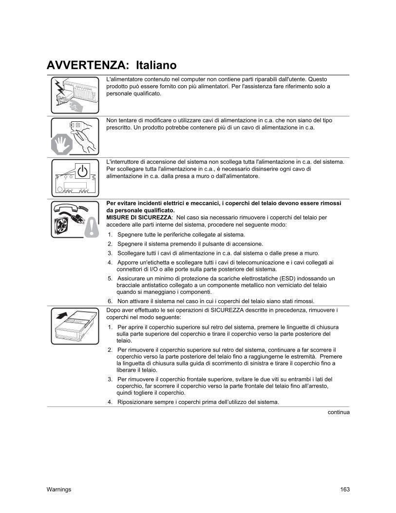
Warnings 163
AVVERTENZA: Italiano
L'alimentatore contenuto nel computer non contiene parti riparabili dall'utente. Questoprodotto può essere fornito con più alimentatori. Per l'assistenza fare riferimento solo apersonale qualificato.
Non tentare di modificare o utilizzare cavi di alimentazione in c.a. che non siano del tipoprescritto. Un prodotto potrebbe contenere più di un cavo di alimentazione in c.a.
L'interruttore di accensione del sistema non scollega tutta l'alimentazione in c.a. del sistema.Per scollegare tutta l'alimentazione in c.a., è necessario disinserire ogni cavo dialimentazione in c.a. dalla presa a muro o dall'alimentatore.
Per evitare incidenti elettrici e meccanici, i coperchi del telaio devono essere rimossida personale qualificato.MISURE DI SICUREZZA: Nel caso sia necessario rimuovere i coperchi del telaio peraccedere alle parti interne del sistema, procedere nel seguente modo:
1. Spegnere tutte le periferiche collegate al sistema.2. Spegnere il sistema premendo il pulsante di accensione.3. Scollegare tutti i cavi di alimentazione in c.a. dal sistema o dalle prese a muro.4. Apporre un'etichetta e scollegare tutti i cavi di telecomunicazione e i cavi collegati ai
connettori di I/O o alle porte sulla parte posteriore del sistema.5. Assicurare un minimo di protezione da scariche elettrostatiche (ESD) indossando un
bracciale antistatico collegato a un componente metallico non verniciato del telaioquando si maneggiano i componenti.
6. Non attivare il sistema nel caso in cui i coperchi del telaio siano stati rimossi.
Dopo aver effettuato le sei operazioni di SICUREZZA descritte in precedenza, rimuovere icoperchi nel modo seguente:
1. Per aprire il coperchio superiore sul retro del sistema, premere le linguette di chiusurasulla parte superiore del coperchio e tirare il coperchio verso la parte posteriore deltelaio.
2. Per rimuovere il coperchio superiore sul retro del sistema, continuare a far scorrere ilcoperchio verso la parte posteriore del telaio fino a raggiungerne le estremità. Premerela linguetta di chiusura sulla guida di scorrimento di sinistra e tirare il coperchio fino aliberare il telaio.
3. Per rimuovere il coperchio frontale superiore, svitare le due viti su entrambi i lati delcoperchio, far scorrere il coperchio verso la parte frontale del telaio fino all’arresto,quindi togliere il coperchio.
4. Riposizionare sempre i coperchi prima dell’utilizzo del sistema.
continua
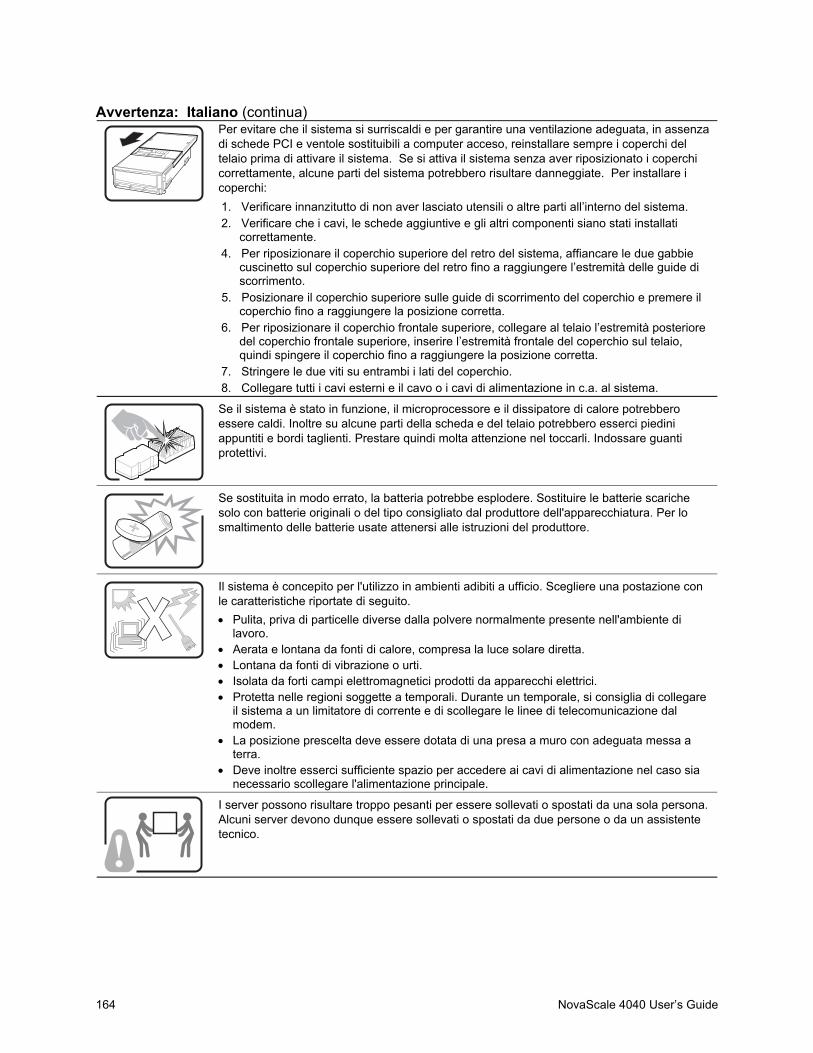
164 NovaScale 4040 User’s Guide
Avvertenza: Italiano (continua)Per evitare che il sistema si surriscaldi e per garantire una ventilazione adeguata, in assenzadi schede PCI e ventole sostituibili a computer acceso, reinstallare sempre i coperchi deltelaio prima di attivare il sistema. Se si attiva il sistema senza aver riposizionato i coperchicorrettamente, alcune parti del sistema potrebbero risultare danneggiate. Per installare icoperchi:1. Verificare innanzitutto di non aver lasciato utensili o altre parti all’interno del sistema.2. Verificare che i cavi, le schede aggiuntive e gli altri componenti siano stati installati
correttamente.4. Per riposizionare il coperchio superiore del retro del sistema, affiancare le due gabbie
cuscinetto sul coperchio superiore del retro fino a raggiungere l’estremità delle guide discorrimento.
5. Posizionare il coperchio superiore sulle guide di scorrimento del coperchio e premere ilcoperchio fino a raggiungere la posizione corretta.
6. Per riposizionare il coperchio frontale superiore, collegare al telaio l’estremità posterioredel coperchio frontale superiore, inserire l’estremità frontale del coperchio sul telaio,quindi spingere il coperchio fino a raggiungere la posizione corretta.
7. Stringere le due viti su entrambi i lati del coperchio.8. Collegare tutti i cavi esterni e il cavo o i cavi di alimentazione in c.a. al sistema.
Se il sistema è stato in funzione, il microprocessore e il dissipatore di calore potrebberoessere caldi. Inoltre su alcune parti della scheda e del telaio potrebbero esserci piediniappuntiti e bordi taglienti. Prestare quindi molta attenzione nel toccarli. Indossare guantiprotettivi.
Se sostituita in modo errato, la batteria potrebbe esplodere. Sostituire le batterie scarichesolo con batterie originali o del tipo consigliato dal produttore dell'apparecchiatura. Per losmaltimento delle batterie usate attenersi alle istruzioni del produttore.
Il sistema è concepito per l'utilizzo in ambienti adibiti a ufficio. Scegliere una postazione conle caratteristiche riportate di seguito.• Pulita, priva di particelle diverse dalla polvere normalmente presente nell'ambiente di
lavoro.• Aerata e lontana da fonti di calore, compresa la luce solare diretta.• Lontana da fonti di vibrazione o urti.• Isolata da forti campi elettromagnetici prodotti da apparecchi elettrici.• Protetta nelle regioni soggette a temporali. Durante un temporale, si consiglia di collegare
il sistema a un limitatore di corrente e di scollegare le linee di telecomunicazione dalmodem.
• La posizione prescelta deve essere dotata di una presa a muro con adeguata messa aterra.
• Deve inoltre esserci sufficiente spazio per accedere ai cavi di alimentazione nel caso sianecessario scollegare l'alimentazione principale.
I server possono risultare troppo pesanti per essere sollevati o spostati da una sola persona.Alcuni server devono dunque essere sollevati o spostati da due persone o da un assistentetecnico.
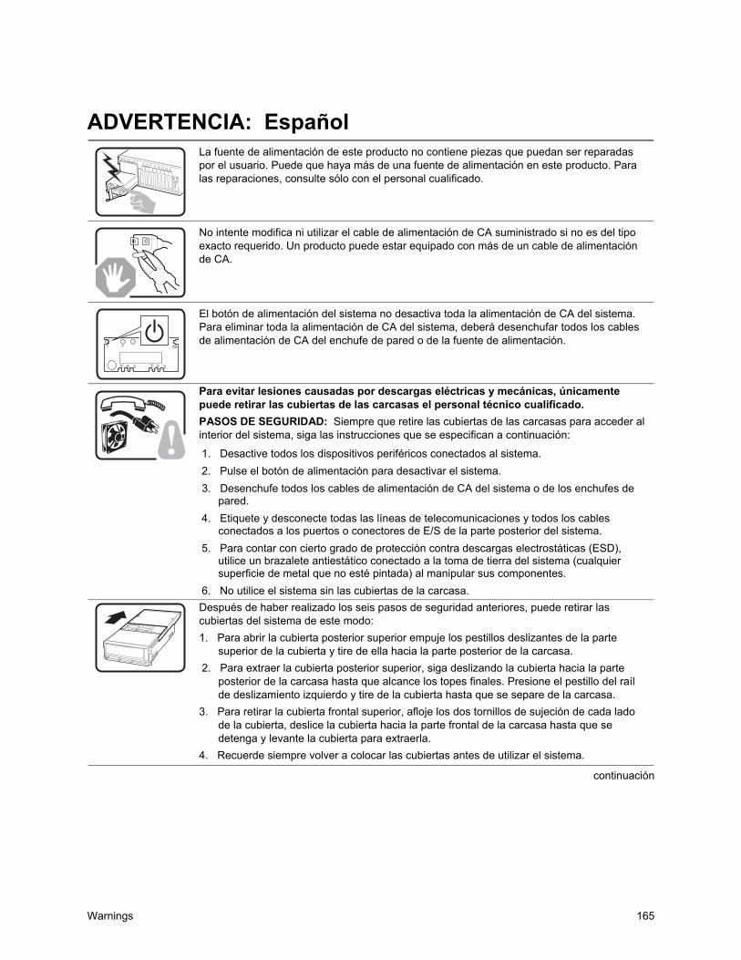
Warnings 165
ADVERTENCIA: Español
La fuente de alimentación de este producto no contiene piezas que puedan ser reparadaspor el usuario. Puede que haya más de una fuente de alimentación en este producto. Paralas reparaciones, consulte sólo con el personal cualificado.
No intente modifica ni utilizar el cable de alimentación de CA suministrado si no es del tipoexacto requerido. Un producto puede estar equipado con más de un cable de alimentaciónde CA.
El botón de alimentación del sistema no desactiva toda la alimentación de CA del sistema.Para eliminar toda la alimentación de CA del sistema, deberá desenchufar todos los cablesde alimentación de CA del enchufe de pared o de la fuente de alimentación.
Para evitar lesiones causadas por descargas eléctricas y mecánicas, únicamentepuede retirar las cubiertas de las carcasas el personal técnico cualificado.PASOS DE SEGURIDAD: Siempre que retire las cubiertas de las carcasas para acceder alinterior del sistema, siga las instrucciones que se especifican a continuación:
1. Desactive todos los dispositivos periféricos conectados al sistema.2. Pulse el botón de alimentación para desactivar el sistema.3. Desenchufe todos los cables de alimentación de CA del sistema o de los enchufes de
pared.4. Etiquete y desconecte todas las líneas de telecomunicaciones y todos los cables
conectados a los puertos o conectores de E/S de la parte posterior del sistema.5. Para contar con cierto grado de protección contra descargas electrostáticas (ESD),
utilice un brazalete antiestático conectado a la toma de tierra del sistema (cualquiersuperficie de metal que no esté pintada) al manipular sus componentes.
6. No utilice el sistema sin las cubiertas de la carcasa.
Después de haber realizado los seis pasos de seguridad anteriores, puede retirar lascubiertas del sistema de este modo:1. Para abrir la cubierta posterior superior empuje los pestillos deslizantes de la parte
superior de la cubierta y tire de ella hacia la parte posterior de la carcasa.2. Para extraer la cubierta posterior superior, siga deslizando la cubierta hacia la parte
posterior de la carcasa hasta que alcance los topes finales. Presione el pestillo del raílde deslizamiento izquierdo y tire de la cubierta hasta que se separe de la carcasa.
3. Para retirar la cubierta frontal superior, afloje los dos tornillos de sujeción de cada ladode la cubierta, deslice la cubierta hacia la parte frontal de la carcasa hasta que sedetenga y levante la cubierta para extraerla.
4. Recuerde siempre volver a colocar las cubiertas antes de utilizar el sistema.
continuación
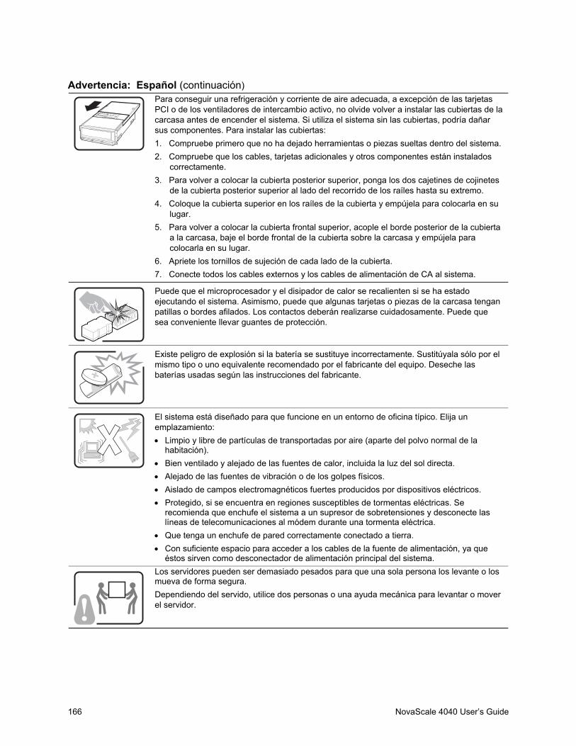
166 NovaScale 4040 User’s Guide
Advertencia: Español (continuación)Para conseguir una refrigeración y corriente de aire adecuada, a excepción de las tarjetasPCI o de los ventiladores de intercambio activo, no olvide volver a instalar las cubiertas de lacarcasa antes de encender el sistema. Si utiliza el sistema sin las cubiertas, podría dañarsus componentes. Para instalar las cubiertas:1. Compruebe primero que no ha dejado herramientas o piezas sueltas dentro del sistema.2. Compruebe que los cables, tarjetas adicionales y otros componentes están instalados
correctamente.3. Para volver a colocar la cubierta posterior superior, ponga los dos cajetines de cojinetes
de la cubierta posterior superior al lado del recorrido de los raíles hasta su extremo.4. Coloque la cubierta superior en los raíles de la cubierta y empújela para colocarla en su
lugar.5. Para volver a colocar la cubierta frontal superior, acople el borde posterior de la cubierta
a la carcasa, baje el borde frontal de la cubierta sobre la carcasa y empújela paracolocarla en su lugar.
6. Apriete los tornillos de sujeción de cada lado de la cubierta.7. Conecte todos los cables externos y los cables de alimentación de CA al sistema.
Puede que el microprocesador y el disipador de calor se recalienten si se ha estadoejecutando el sistema. Asimismo, puede que algunas tarjetas o piezas de la carcasa tenganpatillas o bordes afilados. Los contactos deberán realizarse cuidadosamente. Puede quesea conveniente llevar guantes de protección.
Existe peligro de explosión si la batería se sustituye incorrectamente. Sustitúyala sólo por elmismo tipo o uno equivalente recomendado por el fabricante del equipo. Deseche lasbaterías usadas según las instrucciones del fabricante.
El sistema está diseñado para que funcione en un entorno de oficina típico. Elija unemplazamiento:• Limpio y libre de partículas de transportadas por aire (aparte del polvo normal de la
habitación).• Bien ventilado y alejado de las fuentes de calor, incluida la luz del sol directa.• Alejado de las fuentes de vibración o de los golpes físicos.• Aislado de campos electromagnéticos fuertes producidos por dispositivos eléctricos.• Protegido, si se encuentra en regiones susceptibles de tormentas eléctricas. Se
recomienda que enchufe el sistema a un supresor de sobretensiones y desconecte laslíneas de telecomunicaciones al módem durante una tormenta eléctrica.
• Que tenga un enchufe de pared correctamente conectado a tierra.• Con suficiente espacio para acceder a los cables de la fuente de alimentación, ya que
éstos sirven como desconectador de alimentación principal del sistema.
Los servidores pueden ser demasiado pesados para que una sola persona los levante o losmueva de forma segura.Dependiendo del servido, utilice dos personas o una ayuda mecánica para levantar o moverel servidor.
INI File Format 167
C INI File Format
IntroductionThe FRUSDR utility for EFI allows the FRU information retrieved from the EEPROM to bedisplayed using user-defined strings. Through the use of an INI file you can create strings to bedisplayed and insert information from the data retrieved from the EEPROM into the string. Thisallows you a wide variety of customization.
INI File StructureAn INI file consists of two areas: the header area that is designated by the [INF_FILE] sectionheader and the main body designated by the [DISPLAY] section header.
The [INF_FILE] SectionThe [INF_FILE] must contain three items: Signature, FileFormatVersion, and ManufacturersID(LS byte first). The Signature is to let the utility know that this is an INI file for the FRUSDRutility. The FileFormatVersion is so that future changes to the INI Display format can be trackedand adapted to. The Manufacturer’s ID indicates which of the Multi-record area records are to bedisplayed. The record within the multi-record area for a particular OEM is marked with thatOEM’s ID so that the data can be retrieved and interpreted correctly for that OEM. If theManufacturers ID is not found, the utility exits.
The [DISPLAY] SectionThe Display section consists of a list of entries that contain two components needed for the display.The first component is the “LINE” numbering component. This provides the mechanism forvertical formatting. Line number entries are executed in order. The Line numbers don’tnecessarily correspond to a particular line on the display and will depend on the format strings fromeach line entry that determine whether linefeed and carriage return are used. A maximum of99 lines may be used. The /P command line argument may be used to pause the displayed data sothat it will fit on the screen.
The other component of the Display entry is the format string and data markers. The format stringis similar to a c-style format string. Text from the format string is displayed as written between aset of quotation marks, with the only exceptions being the formatting options. Formatting optionsallows the insertion of data and cursor control.

168 NovaScale 4040 User’s Guide
Currently supported options are as follows:
\n Provides a carriage return and a line feed.
\r Provides a carriage return only.
%s Displays data from the EEPROM that corresponds to the data marker.
%x Displays data in hex format.
Data markers provide a way of identifying which field from the EEPROM is to be displayed. Atable is provided that lists all the supported fields and the data marker associated with each field.
Example of an INI File:[INF_FILE]
Signature=FRUSDR_INI_FILE
FileFormatVersion = 01
ManufacturersID=000157
[DISPLAY]
LINE10= "Chassis Type :%x \n" C1
LINE11= "Chassis Part number :%s \n" C2
LINE03= "INTEL Serial number :%s \n" B4
LINE01= "ACME Part number :%s \n" M5
LINE04= "ACME Device info :%s \n" M6
LINE02= "ACME FRU number :%s \n" M7

INI File Format 169
Table 33. Data MarkersArea Field MarkerChassis Area
Chassis Type C1Chassis Part Number C2Chassis Serial Number C3
Board AreaManufacture Date/Time B1Board Manufacturer B2Board Name B3Board Serial Number B4Board Part Number B5Board FRU ID B6
Product AreaProduct Manufacturer P1Product Name P2Product Part Number P3Product Serial Number P4Product Asset Tag P5Product Version P6Product FRU ID P7
Multi-record areaOEM DATA (part number) M1OEM DATA M2OEM DATA M3OEM DATA M4OEM DATA M5OEM DATA M6OEM DATA M7OEM DATA M8OEM DATA M9

170 NovaScale 4040 User’s Guide

SDRViewer Splash Screen File Format 171
D SDRViewer Splash Screen File Format
The splash screen file contains a header and binary data that holds the Unicode characters and theircolor attributes that are displayed on the screen. The default file name extension of the splashscreen files is *.sph. Table 34 summarizes the content of these files.
✏ NOTESThe last character in the screen cannot be displayed, because it causes thescreen to scroll up. Even though it is required in the file, it is not written tothe screen.
The utility checks that the text mode resolution specified in the splash screenfile is supported by the system. The splash screen is not displayed if the textmode is not supported. In addition, the current text mode is preserved afterthe splash screen is successfully displayed.
Table 34. SDRViewer Splash Screen File FormatField Size (bytes) DescriptionSignature 8 ASCII string “*SPLASH*” that indicates it is a splash screen file.Version 1 File format version: 1 for this specification.Number of Columns (x) 2 Number of columns in the screen. This is text mode resolution of
x (e.g., 80 for text mode 80x25).Number of Rows (y) 2 Number of rows in the screen. This is the text mode resolution
of y (e.g., 25 for text mode 80x25).Screen Attribute 1 Text color and background attributes of entire splash screen
(note that the attribute of each cell overrides this field).Reserved 2Lines 1 through y 4 * x * y Lines consist of all the Unicode characters and their color
attributes. X refers to the number of columns; Y refers to thenumber of rows. Unicode character must be supported by EFI.All the lines are contiguous as a one-dimensional array. The firstbyte is reserved, the second is the character’s color attribute(text background | text color), and the last byte is the 2-byteUnicode character:UINT8 Reserved;
UINT8 attr;
CHAR16 UnicodeChar;

172 NovaScale 4040 User’s Guide

SELViewer Splash Screen File Format 173
E SELViewer Splash Screen File Format
The splash screen file contains a header and binary data that holds the Unicode characters and theircolor attributes that are displayed on the screen. The default file name extension of splash screenfiles is *.sph and Table 36 summarizes the content of these files.
The following keyword is defined to support platform-dependent customizations of the SELViewer. Each of these keywords should appear in the section “[Splash Screen Files]”.
Table 35. Splash Screen File Section Keywords for the SEL.INIKeyword Default PurposeSPH.AA.BB Selenus.sph Indicates the binary file containing the splash screen referenced by the SEL
Viewer. This file contains the splash screen of the language indicated bythe alpha-2 code ‘AA’, in the locale/country indicated by the alpha-2 code‘BB’. For example, the file selenus.sph would contain the splash screen forthe English language and the United States locale.
✏ NOTESThe last character in the screen cannot be displayed because it causes thescreen to scroll up. Even thought it is required in the file, it is not written tothe screen.
The utility checks that the text mode resolution specified in the splash screenfile is supported by the system. The splash screen is not displayed if the textmode is not supported. In addition, the current text mode is preserved afterthe splash screen is successfully displayed.

174 NovaScale 4040 User’s Guide
Table 36. SELViewer Splash Screen File FormatField Size (bytes) DescriptionSignature 8 ASCII string “*SPLASH*” that indicates it is a splash screen file.Version 1 File format version: 1 for this specification.Number ofColumns (x)
2 Number of columns in the screen. This is text mode resolution of x (e.g., 80for text mode 80x25).
Number ofRows (y)
2 Number of rows in the screen. This is the text mode resolution of y (e.g., 25for text mode 80x25).
ScreenAttribute
1 Text color and background attributes of entire splash screen (note that theattribute of each cell overrides this field).
Reserved 2Lines 1through y
4 * x * y Lines consist of all the Unicode characters and their color attributes. Xrefers to the number of columns; Y refers to the number of rows. Unicodecharacter must be supported by EFI.All the lines are contiguous as a one-dimensional array. The first byte isreserved, the second is the character’s color attribute (text background | textcolor), and the last byte is the 2-byte Unicode character:UINT8 Reserved;
UINT8 attr;
CHAR16 UnicodeChar;

Glossary 175
F Glossary
Term DefinitionBIOS Basic Input/Output System. The code that controls the server system startup process.CMOS Complimentary Metal Oxide Semiconductor. Server system startup parameters are stored
in CMOS memory. They can be changed using the system’s Setup utility.DIMM Dual Inline Memory Module.DMA Direct Memory Access. DMA allows data to be sent directly from a component (such as a
disk drive) directly to the memory on the motherboard. The processor does not take part inthe data transfer, which improves system performance.
EFI Extensible Firmware Interface.EMI Electromagnetic Interference.IFB I/O Firmware Bridge. A multifunction device on the I/O Board that acts as a PCI-based Fast
IDE controller.LED Light Emitting Diode. The type of indicator used in this system.LVDS Low-Voltage Differential SCSI.OS Operating System.PCI Peripheral Component Interconnect. PCI is the interconnect system between processors
and devices in the I/O expansion slots.PIO Programmed Input/Output moves data between components in a computer so that all data
must pass through the processor.POST Power On Self-test. The POST runs automatically during the server system startup
sequence.RTC Real Time Clock. Keeps track of the time and date in CMOS memory. A battery backup
keeps the data intact when the server is off.RFI Radio Frequency Interference.SBE Single Bit Error.SCSI Small Computer System Interface.SDRAM Synchronous Dynamic Random Access Memory. SDRAM synchronizes with the bus
frequency.VHDM Connectors used between the boards.

176 NovaScale 4040 User’s Guide
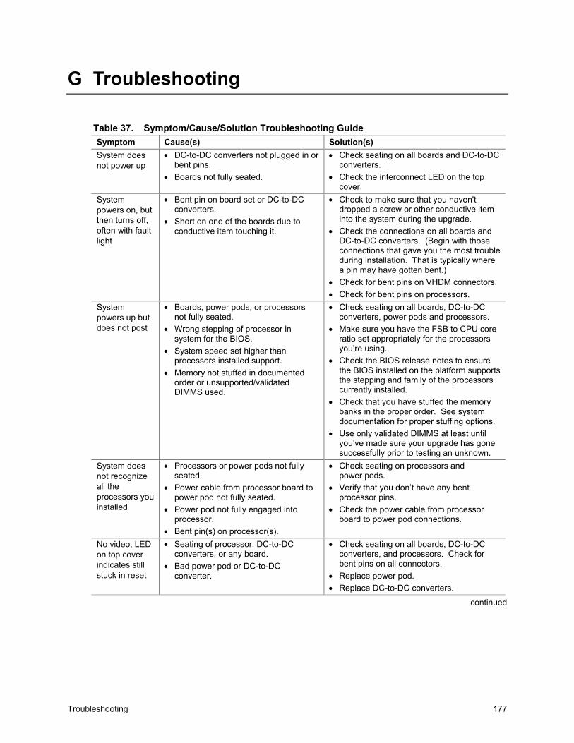
Troubleshooting 177
G Troubleshooting
Table 37. Symptom/Cause/Solution Troubleshooting GuideSymptom Cause(s) Solution(s)System doesnot power up
• DC-to-DC converters not plugged in orbent pins.
• Boards not fully seated.
• Check seating on all boards and DC-to-DCconverters.
• Check the interconnect LED on the topcover.
Systempowers on, butthen turns off,often with faultlight
• Bent pin on board set or DC-to-DCconverters.
• Short on one of the boards due toconductive item touching it.
• Check to make sure that you haven'tdropped a screw or other conductive iteminto the system during the upgrade.
• Check the connections on all boards andDC-to-DC converters. (Begin with thoseconnections that gave you the most troubleduring installation. That is typically wherea pin may have gotten bent.)
• Check for bent pins on VHDM connectors.• Check for bent pins on processors.
Systempowers up butdoes not post
• Boards, power pods, or processorsnot fully seated.
• Wrong stepping of processor insystem for the BIOS.
• System speed set higher thanprocessors installed support.
• Memory not stuffed in documentedorder or unsupported/validatedDIMMS used.
• Check seating on all boards, DC-to-DCconverters, power pods and processors.
• Make sure you have the FSB to CPU coreratio set appropriately for the processorsyou’re using.
• Check the BIOS release notes to ensurethe BIOS installed on the platform supportsthe stepping and family of the processorscurrently installed.
• Check that you have stuffed the memorybanks in the proper order. See systemdocumentation for proper stuffing options.
• Use only validated DIMMS at least untilyou’ve made sure your upgrade has gonesuccessfully prior to testing an unknown.
System doesnot recognizeall theprocessors youinstalled
• Processors or power pods not fullyseated.
• Power cable from processor board topower pod not fully seated.
• Power pod not fully engaged intoprocessor.
• Bent pin(s) on processor(s).
• Check seating on processors andpower pods.
• Verify that you don’t have any bentprocessor pins.
• Check the power cable from processorboard to power pod connections.
No video, LEDon top coverindicates stillstuck in reset
• Seating of processor, DC-to-DCconverters, or any board.
• Bad power pod or DC-to-DCconverter.
• Check seating on all boards, DC-to-DCconverters, and processors. Check forbent pins on all connectors.
• Replace power pod.• Replace DC-to-DC converters.
continued
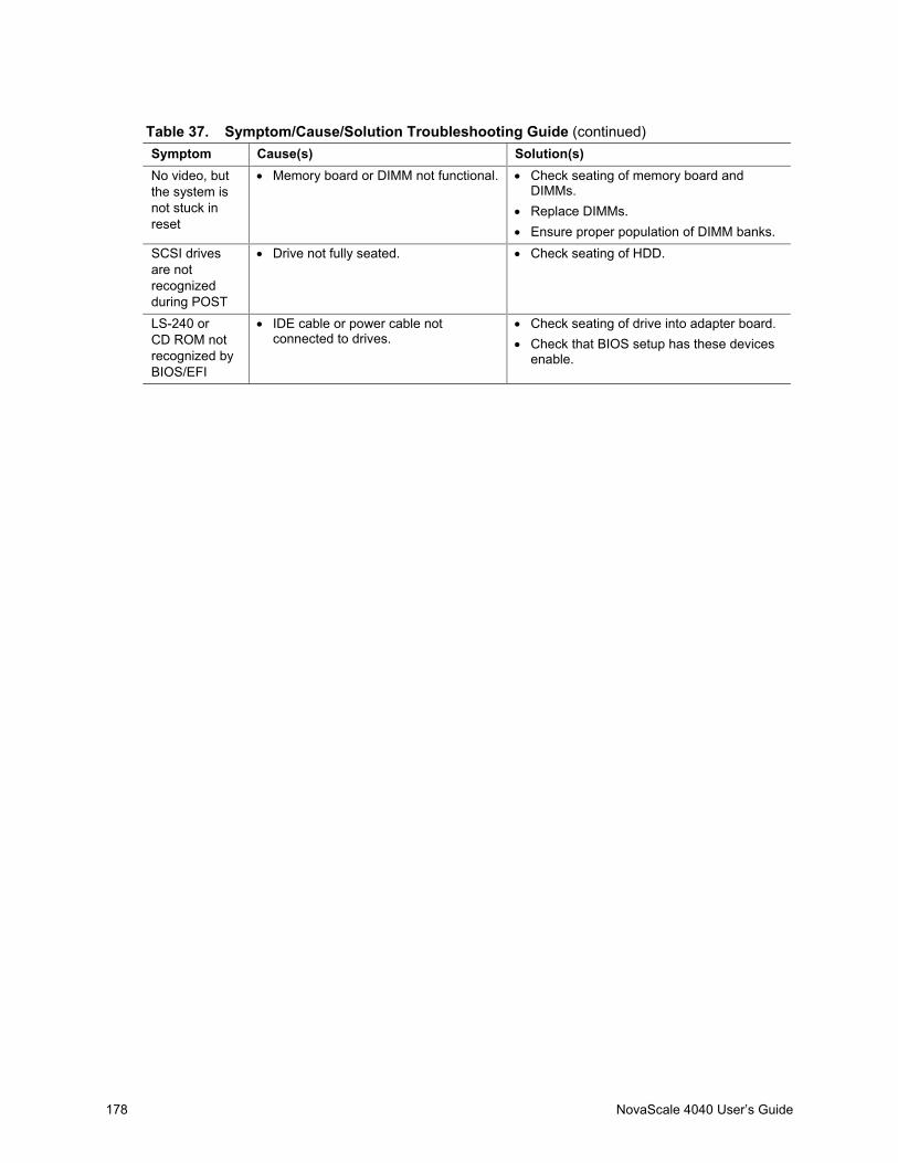
178 NovaScale 4040 User’s Guide
Table 37. Symptom/Cause/Solution Troubleshooting Guide (continued)Symptom Cause(s) Solution(s)No video, butthe system isnot stuck inreset
• Memory board or DIMM not functional. • Check seating of memory board andDIMMs.
• Replace DIMMs.• Ensure proper population of DIMM banks.
SCSI drivesare notrecognizedduring POST
• Drive not fully seated. • Check seating of HDD.
LS-240 orCD ROM notrecognized byBIOS/EFI
• IDE cable or power cable notconnected to drives.
• Check seating of drive into adapter board.• Check that BIOS setup has these devices
enable.
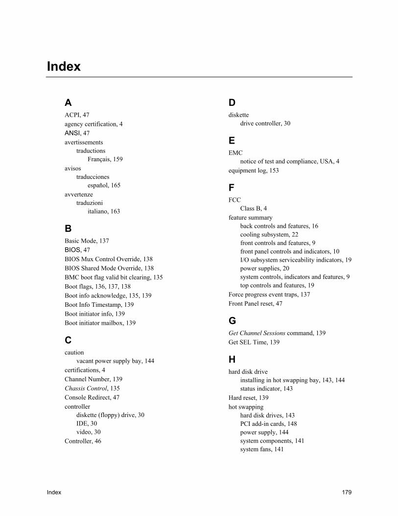
Index 179
Index
AACPI, 47agency certification, 4ANSI, 47avertissements
traductionsFrançais, 159
avisostraducciones
español, 165avvertenze
traduzioniitaliano, 163
BBasic Mode, 137BIOS, 47BIOS Mux Control Override, 138BIOS Shared Mode Override, 138BMC boot flag valid bit clearing, 135Boot flags, 136, 137, 138Boot info acknowledge, 135, 139Boot Info Timestamp, 139Boot initiator info, 139Boot initiator mailbox, 139
Ccaution
vacant power supply bay, 144certifications, 4Channel Number, 139Chassis Control, 135Console Redirect, 47controller
diskette (floppy) drive, 30IDE, 30video, 30
Controller, 46
Ddiskette
drive controller, 30
EEMC
notice of test and compliance, USA, 4equipment log, 153
FFCC
Class B, 4feature summary
back controls and features, 16cooling subsystem, 22front controls and features, 9front panel controls and indicators, 10I/O subsystem serviceability indicators, 19power supplies, 20system controls, indicators and features, 9top controls and features, 19
Force progress event traps, 137Front Panel reset, 47
GGet Channel Sessions command, 139Get SEL Time, 139
Hhard disk drive
installing in hot swapping bay, 143, 144status indicator, 143
Hard reset, 139hot swapping
hard disk drives, 143PCI add-in cards, 148power supply, 144system components, 141system fans, 141

180 NovaScale 4040 User’s Guide
IIANA Enterprise ID Number, 139IDE
controller, 30INI File Format, 167
LLock Sleep Button, 137
Mmemory
video size, 30
PPCI add-in board
installing, 150removing, 148
PCI add-in cardshot swapping, 148
PCI bus hot plug coversinstalling, 150
platform diagnostic tests, 112power cycle, 135, 139power supply
hot swapping, 144installing, 147redundant, 144removing, 146status indicators, 145
Power up, 135, 139
RReset, 47
SSCSI
hard disk driveinstalling in hot swapping bay, 143,
144SDRViewer Splash Screen File Format, 171SELViewer Splash Screen File Format, 173Sensor Event, 45Serial, 47Service partition scan, 134Service partition selector, 134Session ID, 139Set Channel Access, 138Set In Progress, 134Set Selector, 139shutting down the server, 111supplies, 141
TTerminal Mode, 137tools, 141
UUser password bypass, 137
Vvideo
controller, 30memory, 30
WWarnhinweise
ÜbersetzungenDeutsch, 161

Vos remarques sur ce document / Technical publication remark form
Titre / Title : Bull NovaScale 4040 User’s Guide
Nº Reférence / Reference Nº : 86 A1 26EG 03 Daté / Dated : May 2005
ERREURS DETECTEES / ERRORS IN PUBLICATION
AMELIORATIONS SUGGEREES / SUGGESTIONS FOR IMPROVEMENT TO PUBLICATION
Vos remarques et suggestions seront examinées attentivement.Si vous désirez une réponse écrite, veuillez indiquer ci-après votre adresse postale complète.
Your comments will be promptly investigated by qualified technical personnel and action will be taken as required.If you require a written reply, please furnish your complete mailing address below.
NOM / NAME : Date :
SOCIETE / COMPANY :
ADRESSE / ADDRESS :
Remettez cet imprimé à un responsable BULL ou envoyez-le directement à :
Please give this technical publication remark form to your BULL representative or mail to:
BULL CEDOC357 AVENUE PATTONB.P.2084549008 ANGERS CEDEX 01FRANCE

Technical Publications Ordering FormBon de Commande de Documents Techniques
To order additional publications, please fill up a copy of this form and send it via mail to:Pour commander des documents techniques, remplissez une copie de ce formulaire et envoyez-la à :
BULL CEDOCATTN / Mr. L. CHERUBIN357 AVENUE PATTONB.P.2084549008 ANGERS CEDEX 01FRANCE
Phone / Téléphone : +33 (0) 2 41 73 63 96FAX / Télécopie +33 (0) 2 41 73 60 19E–Mail / Courrier Electronique : [email protected]
Or visit our web sites at: / Ou visitez nos sites web à:http://www.logistics.bull.net/cedochttp://www–frec.bull.com http://www.bull.com
CEDOC Reference #No Référence CEDOC
QtyQté
CEDOC Reference #No Référence CEDOC
QtyQté
CEDOC Reference #No Référence CEDOC
QtyQté
_ _ _ _ _ _ _ _ _ [ _ _ ] _ _ _ _ _ _ _ _ _ [ _ _ ] _ _ _ _ _ _ _ _ _ [ _ _ ]
_ _ _ _ _ _ _ _ _ [ _ _ ] _ _ _ _ _ _ _ _ _ [ _ _ ] _ _ _ _ _ _ _ _ _ [ _ _ ]
_ _ _ _ _ _ _ _ _ [ _ _ ] _ _ _ _ _ _ _ _ _ [ _ _ ] _ _ _ _ _ _ _ _ _ [ _ _ ]
_ _ _ _ _ _ _ _ _ [ _ _ ] _ _ _ _ _ _ _ _ _ [ _ _ ] _ _ _ _ _ _ _ _ _ [ _ _ ]
_ _ _ _ _ _ _ _ _ [ _ _ ] _ _ _ _ _ _ _ _ _ [ _ _ ] _ _ _ _ _ _ _ _ _ [ _ _ ]
_ _ _ _ _ _ _ _ _ [ _ _ ] _ _ _ _ _ _ _ _ _ [ _ _ ] _ _ _ _ _ _ _ _ _ [ _ _ ]
_ _ _ _ _ _ _ _ _ [ _ _ ] _ _ _ _ _ _ _ _ _ [ _ _ ] _ _ _ _ _ _ _ _ _ [ _ _ ]
[ _ _ ] : no revision number means latest revision / pas de numéro de révision signifie révision la plus récente
NOM / NAME : Date :
SOCIETE / COMPANY :
ADRESSE / ADDRESS :
PHONE / TELEPHONE : FAX :
E–MAIL :
For Bull Subsidiaries / Pour les Filiales Bull :
Identification:
For Bull Affiliated Customers / Pour les Clients Affiliés Bull :
Customer Code / Code Client :
For Bull Internal Customers / Pour les Clients Internes Bull :
Budgetary Section / Section Budgétaire :
For Others / Pour les Autres :
Please ask your Bull representative. / Merci de demander à votre contact Bull.


BULL CEDOC357 AVENUE PATTONB.P.2084549008 ANGERS CEDEX 01FRANCE
86 A1 26EG 03ORDER REFERENCE