bulletin no. 14 - moncton.cano+14+updated+feb+10+...- provide a completed form 30e (energy...
TRANSCRIPT

1 of 4
From: Randy Richard Date: February 9, 2015 Subject: 2010 National Building Code Adoption and
Associated Process Changes The 2010 National Building Code (NBC) has been adopted by the City of Moncton on January 01, 2015; therefore, several new documents and forms have been produced and process changes have been implemented to incorporate the changes to the NBC. NEW DOCUMENTS
2010 National Building Code Technical Changes (attachment 1E) This document has been produced by the City of Moncton Building Inspection Department and is intended to give a brief overview of some of the changes that will have an impact on the construction industry. This document does not cover the hundreds of changes since the last code cycle; therefore, this document should not be considered as an equivalent to the NBC.
Above Grade Wall Assembly calculation sample (attachment 2E) This is an example of the calculations executed to determine the effective RSI values of wall assemblies. For a list of pre-calculated building assemblies see the City of Moncton website; http://www.moncton.ca/Government/Departments/Building_Inspection/Pre-Calculated_Building_Assemblies.htm
Building Inspection City of Moncton 655 Main Street Moncton, NB E1C 1E8 Phone: (506) 856-4375 Fax: (506) 856-4348
Bulletin No. 14

2 of 4
NEW FORMS Table 1 - New Form Submittal Guide
Building Types and Sizes Part 9
New Form Submittal Energy
Efficiency Design
Submittal (Form 30E)**
Mechanical Ventilation
Record (Form 29E)***
Attic Insulation
Record (Form 28E)***
-Houses with or without a secondary suite -Buildings containing only dwelling units with common spaces <20% of building’s total floor area
-Group C occupancies -Buildings containing Group D, E or F3 occupancies whose combined total floor area < 300m² (3229sq.ft.) (excluding parking garages that serve residential occupancies) -Buildings with a mix of Group C and Group D, E or F3 occupancies where the non-residential portion’s combined total floor area < 300m² (3229sq.ft.) (excluding parking garages that serve residential occupancies
*
-Buildings containing Group D, E or F3 occupancies whose combined total floor area > 300m² (3229sq.ft.) -Buildings containing F2 occupancies of any size
* * *
* Form may be required. ** Form required to be submitted at time of permit application. *** Form required to be submitted to the Building Inspection department prior
to requesting a pre-occupancy inspection.
3 of 4
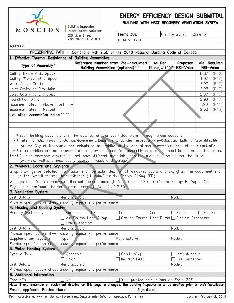
Energy Efficiency Design Submittal (form 30E attached) An Energy Efficiency Design Submittal form is to be filled out and provided to this office at time of permit application for projects that are required to conform to the prescriptive path of section 9.36 of the NBC (see 2010 National Building Code Technical Changes document (attachment 1E) and Table 1 to determine where this applies). Mechanical Ventilation Record (form 29E attached) A Mechanical Ventilation Record form shall be submitted at the end of each project for every ventilation unit installed in residential occupancies classified as Part 9 buildings (see Table 1). Attic Insulation Record (form 28E attached) Attic Insulation Record form shall be submitted at the end of each project where the project is required to conform to section 9.36 of the NBC and has an attic with insulation (See 2010 National Building Code Technical Changes document (attachment 1E) and Table 1 to see where this applies). CHANGES TO THE PERMIT APPLICATION AND INSPECTION PROCESS (SINGLE AND 2 UNIT DWELLINGS ONLY)
Permit Application - Provide a completed form 30E (Energy Efficiency Design Submittal Form). - Provide accurately prepared construction plans with representative cross sections of
all walls, perimeter joist cavities, ceilings and slab details to demonstrate compliance with the minimum RSI values as indicated in the National Building Code Technical Changes document.
- Provide window door and skylight details or shop drawings indicating the sizes, types and thermal resistance values (U-Value) or energy ratings.
- Provide the specification sheets showing the equipment performances for the ventilation system, heating and cooling system and water heating system.
Foundation Inspection - The completion of these items are required prior to requesting an inspection:
o any insulation proposed under the slab or on the exterior wall o the radon pipe as mentioned in the 2010 National Building Code Technical
Changes document
4 of 4
Framing Inspection - No cladding shall be installed prior to having passed the framing inspection. - All mechanical services penetrating or located in the exterior building envelope will
be reviewed for compliance with section 9.36 of the 2010 NBC. - The completion of these items are required prior to requesting an inspection:
o radon protection for service penetrations as outlined in the 2010 National Building Code Technical Changes document
o all rigid insulation proposed on the exterior of the building and below grade o the weather barrier (sheathing membrane) o all flashing, including windows, doors and service penetrations o all windows and doors complete with performance labels
Pre-drywall Inspection - No changes, except confirmation that the insulation installed reflects the plans
submitted with respect to RSI values and attention to the air barrier continuity. Pre-Occupancy Inspection
- Ventilation units, heating units and hot water heaters shall be installed prior to
requesting an inspection.
- The Mechanical Ventilation Record (form 29E) and the Attic Insulation Record (form 28E) are to be submitted to this department prior to requesting an inspection. This form can be delivered to the Building Inspection office or sent via e-mail at [email protected].
o The title of the electronic version shall be as follows:
Civic address, permit number, Form name - All projects that used helical piles require an engineered design and site conformity
report be submitted prior to requesting an inspection. This information can be delivered to the Building Inspection office or sent via e-mail at [email protected].
o The title of the electronic version shall be as follows:
Civic address, permit number, Helical Piles For more information please contact the Building Inspection department at 506 856-4375 or @ [email protected]. Attachments: - 2010 National Building Code Technical Changes (attachment 1E) - Above Grade Wall Assembly calculation example (attachment 2E) - Energy Efficiency Design Submittal (form 30E) - Mechanical Ventilation Record (form 29E) - Attic Insulation Record (form 28E)

Attachment 1E
1 of 6
2010 National Building Code Technical Changes The following document includes updates to the 2010 National Building Code (NBC) that the City of Moncton Building Inspection Department has identified as having the greatest impact on the construction industry.
This document is not designed to be a complete code review of the requirements of the NBC but is only an overview of some of the changes that have occurred in the 2010 National Building Code. Should there be any conflicting information between this documents and the NBC, the NBC shall prevail.
SECONDARY SUITES (SUBSECTION 9.1.2)
• Secondary suites are now defined as self-contained dwelling units (apartments) with a maximum floor area of 80% of the total floor area of all storeys of the principal suite and shall be not more that 80m2 (861sq.ft.) in total floor area.
• Residential units complying with the limits above require a smoke-tight barrier in lieu of fire separation and an STC (Sound Transmission Class) rating of 43. However, other requirements of the NBC will still apply.
STAIRS, RAMPS, HANDRAILS AND GUARDS - HOUSING AND SMALL BUILDINGS (SECTION 9.8)
Height of handrails:
• Minimum height of handrail shall be 865 mm (34”). • Maximum height of handrail shall be 965 mm (38”) (No change).
Stair Uniformity and Tolerances:
• Uniform height in any one flight with a maximum tolerance of 5 mm (3/16”) between adjacent treads or landings and 10 mm (3/8”) between the tallest and shortest risers in a flight.
• Uniform Run in any one flight with a maximum tolerance of 5 mm (3/16”) between adjacent treads and 10 mm (3/8”) between the deepest and shallowest treads in a flight.
Attachment 1E
2 of 6
SPATIAL SEPARATIONS BETWEEN BUILDINGS (SUBSECTION 9.10.15)
The changes related to the spatial separation requirements are numerous and technical; therefore, only the major points are highlighted:
• The protection of projections, for example; roof soffits less than 1.2m (4’) from property line shall have no openings and shall be protected.
• The limits on projections, for example; roof soffits cannot be constructed within 0.45m (1’-6”) set back from property line.
• The limitation on the % of glazed openings, for example; the spacing and area of glazed openings are limited where the set back to the property line is located less that 2m (6’-6”) to the property line.
SMOKE ALARM LOCATIONS (SUBSECTION 9.10.19)
Within dwelling units, smoke alarms are required to be installed on each storey, including the basement level.
Smoke alarms must be installed in all sleeping rooms and if the sleeping rooms are served by a hallway, an additional smoke alarm shall be located within the hallways.
Power supply of smoke alarms shall be installed with a permanent connection to an electrical circuit and have no disconnect switch between the overcurrent device and the smoke alarm.
In the case that regular power supply to the smoke alarm is interrupted, a battery alternative power source is required that can provide power to the smoke alarm for a period of not less than 7 days in the normal condition, followed by 4 minutes of alarm.
SUB-SLAB RADON FLOOR DEPRESSURIZATION ROUGH-IN (SUBSECTION 9.13.4)
In addition to the existing requirements for Radon Protection, radon sub-slab depressurization system must be roughed in at the time of construction. 100mm (4”) of clean granular material must be provided below the slab. A pipe must be installed thru the concrete slab with the inlet at or near the center of the slab and the top of the pipe must be fitted with an air tight cap and labeled “radon”. Refer to Figure 1.

Attachment 1E
3 of 6
Figure 1 - Radon Sub-Slab Rough-in
Take note that the polyethylene sheet material installed under the slab shall conform to CAN/CGSB-51.34M. Where the concrete slab meets the foundation wall, the perimeter of the concrete slab shall be sealed with an approved flexible sealant. Refer to Figure 2.
Figure 2 - Radon Protection at Slab Perimeter
The integrity of the material used in conformance with CAN/CGSB-51.34M shall be maintained and sealed around all service penetrations. Low expansion foam used to seal windows is not permitted.
Attachment 1E
4 of 6
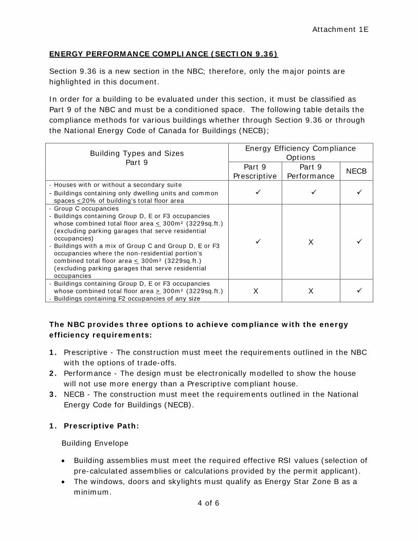
ENERGY PERFORMANCE COMPLIANCE (SECTION 9.36)
Section 9.36 is a new section in the NBC; therefore, only the major points are highlighted in this document.
In order for a building to be evaluated under this section, it must be classified as Part 9 of the NBC and must be a conditioned space. The following table details the compliance methods for various buildings whether through Section 9.36 or through the National Energy Code of Canada for Buildings (NECB);
Building Types and Sizes Part 9
Energy Efficiency Compliance Options
Part 9 Prescriptive
Part 9 Performance
NECB
- Houses with or without a secondary suite - Buildings containing only dwelling units and common
spaces <20% of building’s total floor area
- Group C occupancies - Buildings containing Group D, E or F3 occupancies
whose combined total floor area < 300m² (3229sq.ft.) (excluding parking garages that serve residential occupancies)
- Buildings with a mix of Group C and Group D, E or F3 occupancies where the non-residential portion’s combined total floor area < 300m² (3229sq.ft.) (excluding parking garages that serve residential occupancies
X
- Buildings containing Group D, E or F3 occupancies whose combined total floor area > 300m² (3229sq.ft.)
- Buildings containing F2 occupancies of any size X X
The NBC provides three options to achieve compliance with the energy efficiency requirements:
1. Prescriptive - The construction must meet the requirements outlined in the NBC with the options of trade-offs.
2. Performance - The design must be electronically modelled to show the house will not use more energy than a Prescriptive compliant house.
3. NECB - The construction must meet the requirements outlined in the National Energy Code for Buildings (NECB).
1. Prescriptive Path:
Building Envelope
• Building assemblies must meet the required effective RSI values (selection of pre-calculated assemblies or calculations provided by the permit applicant).
• The windows, doors and skylights must qualify as Energy Star Zone B as a minimum.
Attachment 1E
5 of 6
• The air tightness is similar to current best practices or tested systems.
HVAC Requirements and Service Water Heating Systems
• Minimum performance values (efficiencies) are required for fuel burning furnaces, boilers, stoves, fire places, ground source heat pumps, air source heat pumps, water heaters and HRV’s.
• No minimum performance values are presented for electric heaters and stand-alone forced hot air furnaces.
2. Performance Path: • The proposed house energy consumption must be calculated and compared
to a similar Prescriptive compliant house. • The design must be performed by a registered energy advisor certified by
Natural Resources Canada.
3. National Energy Code of Canada for Buildings (NECB) Path: • The proposed building must be designed and signed off by a qualified
individual.
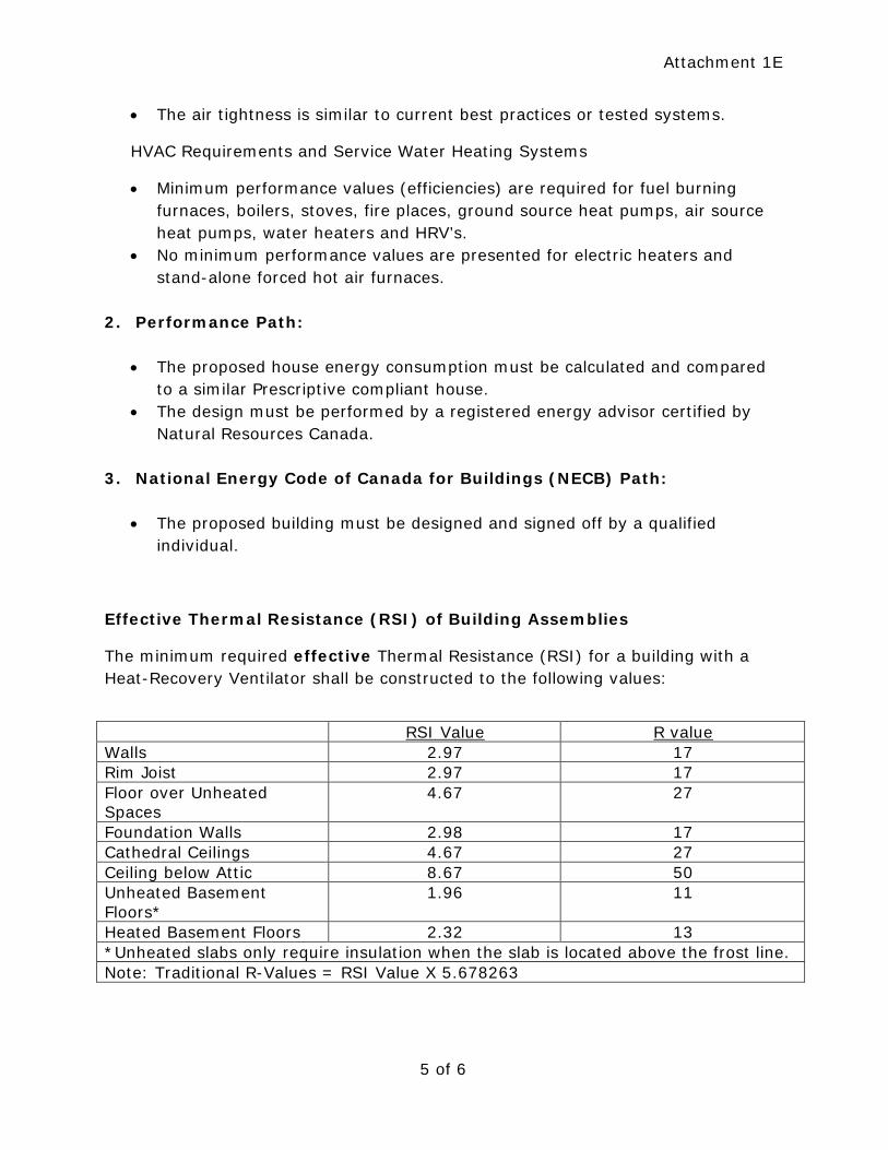
Effective Thermal Resistance (RSI) of Building Assemblies
The minimum required effective Thermal Resistance (RSI) for a building with a Heat-Recovery Ventilator shall be constructed to the following values:
RSI Value R value Walls 2.97 17 Rim Joist 2.97 17 Floor over Unheated Spaces
4.67 27
Foundation Walls 2.98 17 Cathedral Ceilings 4.67 27 Ceiling below Attic 8.67 50 Unheated Basement Floors*
1.96 11
Heated Basement Floors 2.32 13 *Unheated slabs only require insulation when the slab is located above the frost line. Note: Traditional R-Values = RSI Value X 5.678263
Attachment 1E
6 of 6
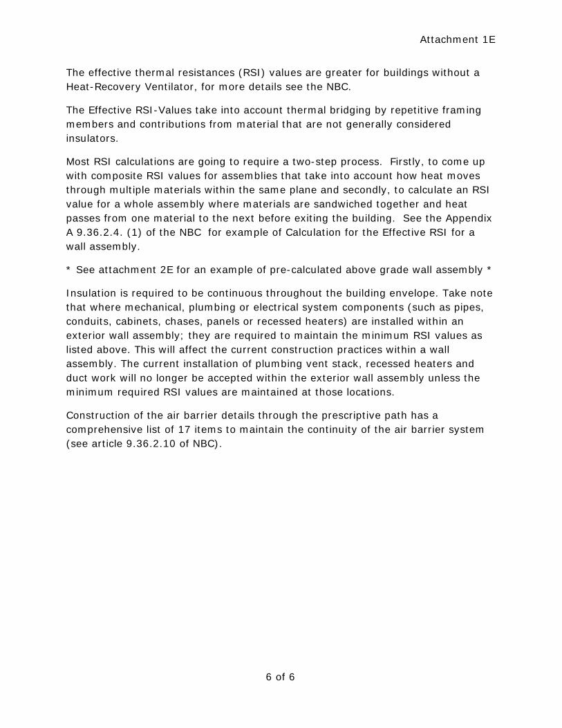
The effective thermal resistances (RSI) values are greater for buildings without a Heat-Recovery Ventilator, for more details see the NBC.
The Effective RSI-Values take into account thermal bridging by repetitive framing members and contributions from material that are not generally considered insulators.
Most RSI calculations are going to require a two-step process. Firstly, to come up with composite RSI values for assemblies that take into account how heat moves through multiple materials within the same plane and secondly, to calculate an RSI value for a whole assembly where materials are sandwiched together and heat passes from one material to the next before exiting the building. See the Appendix A 9.36.2.4. (1) of the NBC for example of Calculation for the Effective RSI for a wall assembly.
* See attachment 2E for an example of pre-calculated above grade wall assembly *
Insulation is required to be continuous throughout the building envelope. Take note that where mechanical, plumbing or electrical system components (such as pipes, conduits, cabinets, chases, panels or recessed heaters) are installed within an exterior wall assembly; they are required to maintain the minimum RSI values as listed above. This will affect the current construction practices within a wall assembly. The current installation of plumbing vent stack, recessed heaters and duct work will no longer be accepted within the exterior wall assembly unless the minimum required RSI values are maintained at those locations.
Construction of the air barrier details through the prescriptive path has a comprehensive list of 17 items to maintain the continuity of the air barrier system (see article 9.36.2.10 of NBC).

Above Grade Wall Assembly
Assembly # MW01
Layer RSI Value R Value1 0.03 0.170348
2 0.11 0.624609
3 N/A N/A
4 0.65 3.690875 0.108903 0.618377
6 2.357204 13.38481
7 N/A N/A
8 0.07747 0.4398959 0.12 0.681392
Outside Air Film
Non‐Insulated Vinyl siding
Weather Barrier House wrap
Inside Air Film13mm (1/2") Gypsum Board
Description: 38x140 (2x6) Studs at 400mm (16") o/c with fibreglass cavity insulation. 11.1mm (7/16") OSB Sheathing and
25mm (1") expanded polystyrene (Type 1) continuous insulation. Exterior finish with vinyl siding, interior finish with 12.7mm
(1/2") gypsum board.
25mm (1") expanded polystyrene (Type 1)11.1mm (7/16") OSB Sheathing
38x140 (2X6) @ 400mm (16") o/c with RSI3.52 (R20) Fiberglass batt *
6 mil. Polyethylene
Assembly Components (layer listed from exterior to interior)
Total 3.45 19.6
Note:
The thermal resistance values of each continuous layer incorporated in the assembly are from A‐9.36.2.4.(1)D.
RSIparallel =
Parallel Heat Flow Calculation: +
% Area of Framing 23% Value of the area of framing member obtained from Table A‐9.36.2.4.(1)A
% Area of Cavity 77% Values of the area of cavity obtained from Table A‐9.36.2.4.(1)A
RSI Framing 1.18745
RSI Cavity 3.34
RSI Parrallel * 2.357204
Reff =19.6
eff = effective thermal resistance
Note: The above values and references are from the 2010 National Building Code of Canada.This document is intended to be
used for reference purposes. The assembly components shall be detailed in a cross section on the submitted plans. For a list
of pre‐calculated assemblies, see the City of Moncton website:
http://www.moncton.ca/Government/Departments/Building_Inspection/Pre‐Calculated_Building_Assemblies.htm
RSIeff = 3.45 (m²∙K)/W
100
% area of framing % area of cavity
RSIF RSIC