bulletin - ursi.org · the radio science bulletin no 338 (september 2011) 5 letter to the editor...
TRANSCRIPT

UNIONRADIO-SCIENTIFIQUE
INTERNATIONALE
INTERNATIONALUNION OF
RADIO SCIENCE
ISS
N 1
024-
4530
URSI, c/o Ghent University (INTEC)St.-Pietersnieuwstraat 41, B-9000 Gent (Belgium)
No 338September 2011R
adio
Sci
ence
Bul
letin
Prof. P. Lagasse Secretary General
Prof. S. Ananthakrishnan Vice-President
Prof. F. Lefeuvre Past President
Dr. P. Wilkinson President
Prof. M. Ando Vice-President
Prof. P. Cannon Vice-President
Prof. G. Uslenghi Vice-President

2 The Radio Science Bulletin No 338 (September 2011)
Front cover: The new URSI Board of Officers. For more information on the newly elected officers, please turn to pp. 46-47 of this Bulletin..
Editor-in-ChiEf EditorURSI Secretary General W. Ross StonePaul Lagasse 840 Armada TerraceDept. of Information Technology San Diego, CA92106Ghent University USASt. Pietersnieuwstraat 41 Tel: +1 (619) 222-1915B-9000 Gent Fax: +1 (619) 222-1606Belgium E-mail: [email protected].: (32) 9-264 33 20 Fax : (32) 9-264 42 88 E-mail: [email protected]
For information, please contact :The URSI Secretariat
c/o Ghent University (INTEC)Sint-Pietersnieuwstraat 41, B-9000 Gent, Belgium
Tel.: (32) 9-264 33 20, Fax: (32) 9-264 42 88E-mail: [email protected]
http://www.ursi.org
EditorialadvisoryBoardFrançois Lefeuvre(URSI President)
W. Ross StoneProduCtionEditors
Inge HeleuInge Lievens
sEniorassoCiatEEditorJ. Volakis
O. Santolik (RRS)assoCiatEEditorforaBstraCts
P. WatsonassoCiatEEditorforBookrEviEws
K. SchlegelassoCiatEEditorsP. Banerjee (Com. A)A. Sihvola (Com. B)S. Salous (Com. C)P-N Favennec (Com. D)D. Giri (Com. E)
S. Paloscia (Com. F)I. Stanislawska (Com. G)M. Oppenheim (Com. H)J. Baars (Com. J)E. Topsakal (Com. K)
ContentsEditorial ....................................................................................................................... 3Letter to the Editor ..................................................................................................... 5URSI Commission E Electromagnetic Environment and Interference
Symposium .............................................................................................................. 6The Dipole Moment (DM) and Recursive Update in Frequency Domain (RUFD)
Methods: Two Novel Techniques in Computational Electromagnetics............. 7On a Technique for Supplying Power to Global Radio Relays for High-Altitude
Platforms by Means of Microwave Beams ......................................................... 25Triennial Reports Commissions ............................................................................... 32XXXth General Assembly and Scientific Symposium ........................................... 46Radio-Frequency Radiation Safety and Health ..................................................... 54The Unusual Story of the IARC Working Group on Radio-Frequency Electromagnetic Fields and Mobile Phones
Conferences ............................................................................................................... 56News from the URSI Community ............................................................................ 58Information for authors ........................................................................................... 61
The International Union of Radio Science (URSI) is a foundation Union (1919) of the International Council of Scientific Unions as direct and immediate successor of the Commission Internationale de Télégraphie Sans Fil which dates from 1913.Unless marked otherwise, all material in this issue is under copyright © 2011 by Radio Science Press, Belgium, acting as agent and trustee for the International Union of Radio Science (URSI). All rights reserved. Radio science researchers and instructors are permitted to copy, for non-commercial use without fee and with credit to the source, material covered by such (URSI) copyright. Permission to use author-copyrighted material must be obtained from the authors concerned.The articles published in the Radio Science Bulletin reflect the authors’ opinions and are published as presented. Their inclusion in this publication does not necessarily constitute endorsement by the publisher. Neither URSI, nor Radio Science Press, nor its contributors accept liability for errors or consequential damages.

The Radio Science Bulletin No 338 (September 2011) 3
EditorialThe XXXth URSI General Assembly
and Scientific Symposium in August in Istanbul, Turkey, was outstanding! The Chair of the Organizing Committee, Hamit Serbest; the Vice Chair, Ayhan Altıntaş; the Coordinator of the Scientific Program, George Uslenghi; and all of the members of the various committees that made this GASS such a success deserve our heartfelt thanks. The hospitality shown to the attendees by our Turkish hosts was wonderful. I hope you were able to attend. If not, the proceedings of the XXXth GASS are available on the URSI Web site at http://www.ursi.org/en/general_assemblies_proceedings.asp. The record of the GASS will be available via a link under the General Assemblies tab at the URSI home page: http://www.ursi.org.
The Council voted to accept the proposal of China (CIE) to hold the XXXIth GASS in Beijing in August, 2014. I’m sure we can look forward to an equally successful General Assembly there.
Our.Papers
In their invited Review of Radio Science from Commission B, Raj Mittra, Chiara Pelletti, Kadappan Panyappan, and Agostino Monorchio present two new computational techniques for general electromagnetic simulation. These are the Dipole Moment technique, and the Recursive Update in Frequency Domain method. The paper begins with an overview of limitations of existing computational techniques that are overcome by these two new methods. The Dipole Moment technique can be used for problems where the traditional Method of Moments (MoM) can be computationally expensive and difficult to apply, including problems involving inhomogeneous materials as well as PECs (perfect electric conductors), without the use of Green’s functions. The technique avoids the low-frequency problems associated with the MoM. The Dipole Moment technique works well for situations where the MoM results in ill-conditioned matrices, such as when dealing with very thin structures. The technique also handles multi-scale problems quite well. The Recursive Update in Frequency Domain method does not rely on iterative or inversion techniques, and has most of the advantages of time-domain methods, although it is a general frequency-domain method. It avoids ill-conditioned matrices and the need for pre-conditioners, and inherently can be parallelized. The paper begins with a presentation of the Dipole Moment technique. The concepts and basic equations are introduced, and then formulations are given for PEC objects and dielectric objects. Examples of numerical results are
presented for both types of objects. Methods of enhancing the computational performance of the technique are discussed, along with a number of its important computational and practical aspects. The Recursive Update in Frequency Domain method is then introduced, and its algorithm is described. Numerical examples are presented for PEC, dielectric, and scatterers that are a combination PECs and dielectrics. The authors follow this with a new method for handling multi-scale problems: problems that involve simulating structures that contain elements requiring
widely varying levels of computational resolution. They show how a hybrid combination of the Dipole Moment and Recursive Update in Frequency Domain methods can be exceptionally effective in solving such problems. They present both iterative and self-consistent schemes for this hybridization, and illustrate both with numerical examples. The paper concludes with a summary of the improvements offered by these techniques, and some information regarding additional possible enhancements.
The efforts of Giuliano Manara, Associate Editor of Commission B, in bringing us this Review are gratefully acknowledged.
High-altitude platforms (HAPs) are an area of
significant research for radio scientists. They offer substantial interesting possibilities for communications, remote sensing, and surveillance. A fundamental challenge for high-altitude platforms is getting power to them. The paper by R. B. Vaganov, I. P. Korshunov, E. N. Korshunova, and A. D. Shatrov presents reasons why the use of a power beam with a Rayleigh distribution has significant potential advantages over the Gaussian-distributed beam normally assumed for transmitting power to such platforms. The paper begins with a review of the major factors affecting the choice of beam parameters for wireless-power-transmission systems. The geometry, dimensions, and other important parameters of a wireless-power-transmission system are explained. An analysis of the maximum power level that can be transmitted by a wireless-power-transmission system for a given system architecture, subject to the basic constraints on such systems, is then presented. Part of this analysis is a comparison of the power transmitted by beams with field intensities that have Gaussian and Rayleigh distributions. It is shown that the Rayleigh distribution results in an advantageous mode structure. The analytical expressions are then evaluated numerically to provide comparisons of the results that can be obtained from wireless-power-transmission systems using each type of distribution. These numerical results show that for typical sets of system parameters, about twice as much power can be delivered

4 The Radio Science Bulletin No 338 (September 2011)
using a Rayleigh distribution as can be delivered using a Gaussian distribution, while satisfying the constraints on allowable diffracted background levels. The analysis and results are shown to be applicable to quite general wireless-power-transmission systems.
Our.Other.Contributions
Kristian Schlegel has brought us reviews of two new books of interest to radio scientists. Jim Lin takes a critical editorial look at a recent announcement regarding the possible risk of cancer associated with cell-phone use in his “Radio-Frequency Radiation Safety and Health” column. We have a letter to the Editor relating to quality in conference presentations. The triennial reports from Commissions A, C, and F appear in this issue. There is also information on the XXXth URSI GASS, including an announcement of the newly elected URSI officers, information on the Young Scientist program, and the resolutions passed by Council.
Finally, Commission E is starting what it is hoped will become a triennial Commission symposium, similar to the triennial symposia currently organized by several of the other URSI Commissions. This is the URSI Commission E Electromagnetic Environment and Interference Symposium (EEIS 2012), to be held for the first time in Cape Town, South Africa, September 2-7, 2012. An announcement and call for papers for this symposium appears in this issue. Note that this symposium is being held in conjunction with two other meetings, the International Conference on Electromagnetics for Advanced Applications (ICEAA2012) and the IEEE Antennas and Propagation for Wireless Communication conference (APWC2012). All three are being held together at the same time, and taken together, cover topics of interest to all 10 of the URSI Commissions. You may want to consider these conferences: Cape Town, South Africa, is a very exciting venue!
Thank.You!
Since December 2002, Phil Wilkinson has served as Senior Associate Editor of the Radio Science Bulletin, coordinating the Reviews of Radio Science. He has done an outstanding job of this. He has helped to bring a very large number of excellent Reviews to these pages and to the URSI community of Radioscientists. His efforts are very much appreciated. Phil was elected President of URSI in Istanbul, and is thus stepping down from his editorial role.
Our new Senior Associate Editor for the Reviews of Radio Science is Ondrej Santolic. Ondrej is in the Department of Space Physics of the Institute of Atmospheric Physics, Academy of Sciences of the Czech Republic. We welcome him to the staff of the Bulletin.
With the XXXth General Assembly, we mark a change in most of the Commission Associate Editors. The newly appointed Associate Editors for the current triennium are listed on the inside of the front cover of this issue. The efforts of the outgoing Commission Associate Editors are greatly appreciated. They have done a very good job of bringing URSI Radioscientists an excellent group of Reviews and other papers from the Commissions.
Send.Your.Papers!
Please consider the Radio Science Bulletin if you have a paper that is of wider interest to URSI Radioscientists. This is the only publication that goes to all URSI Radioscientists. We are fully peer-reviewed, and abstracted and indexed in INSPEC. We have no page limits or page charges. At the moment, we are able to publish papers that have been accepted for publication in the next issue, without any delay. Please contact me if you have a paper you believe would be appropriate.
Correction The subheading on the conference report, “2010 ICEAA Offshore: International Conference on Electromagnetics in Advanced Applications,” which appeared on p. 64 of the June 2011 Radio Science Bulletin (No. 337), incorrectly indicated that the conference was held in Torino, Italy. As correctly explained in the report, the conference was held in Sydney, Australia.

The Radio Science Bulletin No 338 (September 2011) 5
Letter to the Editor
On.the.Quality.of.Presentations
For more than 40 years (my first URSI GA was the Munich meeting in 1966), I have been dismayed, and sometimes upset, by the lack of care and clarity many speakers devote to the presentation of their contribution. The epidiascope had been replaced by the overhead projector. This induced some speakers to write their 10-minute talk in real time – in sometimes illegible handwriting – onto the foil, slowly filling the roll and never finishing their “talk” on time. Others would come with a stack of prepared transparent sheets, again in handwriting and full of smudges and crossed-out sentences. It was no fun to witness these presentations. The only improvement with respect to the age of the blackboard was that most speakers now did not turn their back to the audience while speaking.
The emergence of PowerPoint and computer-connected projectors unfortunately has led to new habits that continue to hinder an optimal communication between presenter and audience/viewers. The two most common nuisances are the following.
The full text of the presentation is written onto a number of slides, which the presenter then reads aloud from beginning to end. This may be convenient for people who are either deaf or blind, but for the great majority of the audience, this is “double speak.” The presenter can’t possibly read as fast as the viewer can read (although I witnessed one example where the speaker came close, becoming essentially incomprehensible in the process), and the result is boredom among the audience. It would be better that the speaker either shuts up or drops the slides.
In a good presentation, the content of the slides should be limited to keywords, and numerical (not too much!) and graphical data, which the eye is able to quickly grasp. The speaker should guide the audience through the material with language, which is not to be found on the slide. A superb example of this was presented in the General Lecture at the Istanbul GASS, “Satellite Navigation: Present and Future,” by Prof. P. K. Enge, of Stanford University.
With presentation programs like Keynote and PowerPoint becoming ever more fanciful and rich in features, many a presenter cannot escape the tendency to behave more as an artist than as a scientist presenting comprehensible content. Multi-colored slides are filled with an array of smaller pictures in a plethora of font sizes and colors. One looses sight of the forest for the trees. Particularly
annoying is the use of weird backgrounds (one’s favorite radio telescope in vague outlines) upon which text is placed in badly matching color.
For instance, rather dark blue is a favorite background color (also on television), and seems to offer some physiological advantages. White text on this background is full of contrast. For emphasis, e.g., headings or keywords within the text, many people use red ink. This looks quite OK on your computer screen, but in projection, all contrast is gone, and the text is barely or not at all readable. This is not the purpose of emphasis, I would think. A similar effect can be observed by the use of yellow and cyan color in line graphs.
Institutes sometimes create standard layouts for backgrounds on which the author enters his or her content. This often causes problems, for instance, where the text runs over a fixed header or footer. I have also noticed a tendency to use a background with an intensity gradient across the screen. While the dark background at the top renders the white text well readable, close to the bottom, the text disappears into the light background and information is lost.
There are other annoyances, such as walking away from the microphone, nervously moving the pointer in circles over the screen, and not staying within the allotted time. In my view, these are less distracting than the above examples.
With a little bit of care and common sense, these annoying aspects of presentations could be avoided. By this, I believe, the overall quality of a conference would be improved. Authors would be remembered by the scientific aspects of their work, rather than by the poor presentation in which the science is hard to discern.
In the USA, graduate students must pass a foreign-language test. They may profit more from a short course in preparing and delivering colloquia and conference contributions. Actually, these rules should be taught to all undergraduates before they ever make a presentation themselves. Professors should give the good example.
Jacob W. M. BaarsMax-Planck-Institut für Radioastronomie
Bonn, Germany
E-mail: [email protected]

6 The Radio Science Bulletin No 338 (September 2011)
URSI Commission E Electromagnetic Environment and Interference Symposium
Conference.Description
The first Electromagnetic Environment and Interference Symposium (EEIS 2012) is being organized by Commission E of the International Union of Radio Science (URSI), in coordination with the ICEAA and IEEE APWC conferences. The three conferences will be held concurrently at the Cape Sun Hotel in Cape Town, South Africa, from Sunday, September 2, through Friday, September 7, 2012. The three conferences share a common organization, registration fee, submission site, welcoming reception, coffee and lunch breaks, banquet, and social program. Detailed information can be found on the conferences Web site: http://www.iceaa-offshore.org. EEIS 2012 will consist of invited and contributed papers, workshops and short courses, and business sessions.
Suggested.Topics.for.EEIS
• Effects of natural and intentional emissions on system performance
• Effects of noise on system performance
• High-power electromagnetic effects on system performance
• Scientific basis of noise and interference control
• Spectrum management and utilization
• Geo-electric and geomagnetic fields, and seismic- associated electromagnetic fields
• Intentional EMI
• High-power sources
• Protection of electronic systems
• Computational modeling
• Measurement technologies and standards
Information.for.Authors
Authors must submit a full-page abstract electronically by March 3, 2012. Authors of accepted contributions must register electronically by June 8, 2012. Instructions can be found on the Web site. Each registered author may present no more than two papers. All papers must be presented by one of the authors. Authors who want their paper to be published on IEEE Xplore should follow the instructions on the Web site. Selected authors of EEIS will be invited to submit a full-length paper for possible publication in the URSI Radio Science Bulletin.
Deadlines
Abstract submission: March 3, 2012
Notification of acceptance: April 13, 2012
Presenter registration: June 8, 2012
Contact.Information
Prof. Alexander P. J. Van Deursen, EEIS Chair E-mail: [email protected]
Dr. Dave V. Giri, EEIS Vice ChairE-mail: [email protected]
Inquiries
Prof. Roberto D. GragliaChair of Organizing CommitteeE-mail: [email protected]
Prof. Piergiorgio L. E. UslenghiChair of Scientific CommitteeE-mail: [email protected]
Prof. David B. DavidsonChair of Local Organizing CommitteeE-mail: [email protected]

The Radio Science Bulletin No 338 (September 2011) 7
The Dipole Moment (DM) and Recursive Update in Frequency
Domain (RUFD) Methods: Two Novel Techniques in
Computational Electromagnetics
Raj Mittra Chiara Pelletti
Kadappan Panyappan Agostino Monorchio
1..Introduction
In this paper, we begin by introducing a novel concept for formulating electromagnetic simulation problems that is based on the use of the Dipole Moment (DM) approach, which has several desirable features. First, it circumvents the need to deal with the singularity that is inherently encountered during the process of evaluating the matrix elements in the conventional Method of Moments (MoM) formulation based on the Green’s function approach. Second, it handles both dielectric and conducting materials, be they lossy or lossless, in a universal manner, without employing different starting points for the formulation. This enables us to handle inhomogeneous problems in a convenient manner using a single formulation. Third, it does not suffer from the so-called “low-frequency breakdown” problem in the conventional MoM formulation, which is presently handled by using special basis functions, such as the loop-star. Fourth, it enables us to hybridize with finite methods to solve multi-scale problems in a convenient manner.
As is well known, with the advent of sub-micron technologies and increasing awareness of electromagnetic interference and compatibility (EMI/EMC) issues, designers are often interested in deriving full-wave solutions of complete systems. These take into account a wide variety of complex environments in which an antenna or a scatterer may be located. However, deriving full-wave solutions of such complex problems is challenging, especially when dealing with those that involve multi-scale geometries with very fine features. The well-established methods, such as the time-domain technique, FDTD, as well as the frequency-domain methods, FEM and MoM, are often pushed to the
Raj Mittra, Chiara Pelletti, and Kadappan Panyappan are with the EMC Lab, 319 Electrical Engineering East, Penn State University, University Park, PA 16802; e-mail: [email protected]. Chiara Pelletti and Agostino Monorchio are with the Department of Information Engineering, University of Pisa, Via Caruso, I-56126 Pisa, Italy.
limits of their capabilities when attempting to simulate these types of problems. Our objective in this work is to present a new physics-based formulation, namely the Dipole Moment approach, which is well suited for addressing the above-mentioned problems.
Since the Dipole Moment formulation does not employ the Green’s functions, or the vector and scalar potentials, it helps to circumvent two of the key sources of difficulties in the conventional MoM formulation. These are the singularity and low-frequency problems. Specifically, we show that there are no singularities that we need to be concerned with in the Dipole Moment formulation. This therefore obviates the need for special techniques designed to deal with the integration of these singularities. Yet another salutary feature of the Dipole Moment approach is its ability to handle thin and lossy structures, regardless of whether they are metallic or dielectric types, or even combinations thereof. The Dipole Moment formulation can handle these types of objects with ease, without running into ill-conditioning problems. This is true even for very thin wire-like or surface-type structures, which lead to poorly-conditioned MoM matrices, when these problems are formulated in the conventional manner using the Green’s function. The technique is valid over the entire frequency range, from low to high, and, as mentioned before, it does not require us to switch to special basis functions to mitigate the so-called “low frequency” problem.
We should point out that the underlying concept of the Dipole Moment approach is similar to the well- known Discrete Dipole Approximation (DDA) [1], which is often used in physics. The Discrete Dipole Approximation defines a lattice described by the locations and distances
This is an invited Review of Radio Science from Commission B

8 The Radio Science Bulletin No 338 (September 2011)
between an array of elements, and then builds and solves a matrix equation by accounting for the contributions on each element due to all of the others, as well as due to the incident field. Despite this similarity, there are two main differences between the Dipole Moment and Discrete Dipole Approximation approaches. First, in contrast to the Discrete Dipole Approximation, the Dipole Moment approach utilizes a spherical building block, for which the associated scattered fields are available in closed forms. Second, the Discrete Dipole Approximation solves a matrix equation for the weights of the polarizations, while the Dipole Moment solves for the weights of the dipole moments, instead.
One consequence of these differences in the two formulations is that unlike the Discrete Dipole Approximation, the Dipole Moment approach can handle arbitrary dielectric and/or PEC objects, or combinations thereof.
The paper also introduces a complementary CEM (computational electromagnetics) algorithm, namely RUFD (Recursive Update in Frequency Domain). This is a general-purpose frequency-domain technique, which still preserves the salutary features of the time-domain methods. Unlike other frequency-domain Maxwell solvers, Recursive Update in Frequency Domain neither relies upon iterative nor on inversion techniques. The algorithm also preserves the advantages of the parallelizability, which is a highly desirable attribute of computational electromagnetics solvers using the difference form of Maxwell’s equations. Since Recursive Update in Frequency Domain solves Maxwell’s equations in a recursive manner without using either iteration or inversion, the problems of dealing with ill-conditioned matrices or constructing robust pre-conditioners are totally avoided. Also, as a frequency-domain solver, it can conveniently handle dispersive media, including plasmonics, although special treatments are needed when ε and/or µ are negative.
It is well known that the conventional time-domain technique, namely the FDTD, demands extensive computational resources when solving either low-frequency problems or when dealing with dispersive media. Not only the MoM, but even FEM-based techniques, also suffer from the low-frequency problem. It is thus evident that a technique that can deal with the low-frequency problem without using pre-conditioners and/or special basis functions would be a very desirable addition to the computational electromagnetics repertoire. An enhanced version of the Recursive Update in Frequency Domain, namely νCFDTD, is also mentioned, and is designed to fill this gap in a seamless and numerically efficient manner.
Finally, the paper shows how the two methods can be blended to yield a hybrid approach, referred to herein as Dipole Moment–Recursive Update in Frequency Domain, to handle multi-scale problems in a convenient manner.
2..Dipole.Moment.Approach
2.1.Introduction.to.Dipole.Moment.Method
Formulating integral equations via the use of Green’s function is a well-established and universally accepted method [2-4], which has been a staple for computational electromagnetics problems for many years. However, as alluded to earlier, MoM requires special treatment at low frequencies, and needs to deal with the singular and/or hyper-singular behaviors of the Green’s function. Additionally, both frequency-domain techniques, FEM and MoM, experience difficulties when handling multi-scale geometries because the associated matrices for these problems can be ill-conditioned. In this section, we introduce a universal MoM-like, Dipole-Moment-based formulation [5] to obviate the disadvantages of the conventional frequency-domain techniques.
2.2.Dipole.Moment.Concept
To develop the Dipole Moment concept, we first consider our building block, a sphere, which is illuminated by a plane wave. The resulting scattered fields can be determined analytically because of its spherical symmetry. A PEC sphere of radius a, immersed in free space and illuminated by a plane wave 0
zjk zxE E e−= , produces the
following scattered electric far fields in the limit of 0ka → :
( ) ( )30
0lim cos cos 1 2
jkrs
ka
eE E kakrθ φ θ−
→= − , (1a)
( ) ( )3
00
lim cos 1 2cos 1jkr
ska
eE E kakrφ φ θ−
→= − . (1b)
The above Equation (1) is derived by using spherical wave functions [6]. Upon closer analysis, we can recognize the fact that Equation (1) resembles the far fields radiated from an x-directed electric dipole and a y-directed magnetic dipole, with moments given by
( )30 2
4x
jIl E kakπ
η= , (2a)
( )30 2
2yKl E ka
jkπ
= . (2b)

The Radio Science Bulletin No 338 (September 2011) 9
Along the same lines, the equivalent dipole moments for a lossless dielectric sphere of radius a, with a relative dielectric constant of rε and a relative permeability of rµare found to be
( )30 2142
rx
r
jIl E kak
επεη
−=
+, (3a)
( )30 2
122
rx
rKl E ka
jkµπµ
−=
+. (3b)
Equation (3) can be readily modified for a lossy medium by replacing the real valued rε and rµ with their complex permittivity, ε , and permeability, µ , respectively. It is important to note the fact that the magnetic dipole moment goes to zero for non-magnetic media with 1rµ =, and similarly, the electric dipole moment goes to zero for magnetic media with 1rε = .
The dipole-moment representation of a scatterer therefore generates the same far fields as those scattered by the original objects.
However, what has not been realized in the past, and what can be proven analytically [7], is that for a sphere with a radius that is electrically small, the dipole-moment fields exactly match the original fields scattered by the sphere, all the way up to its surface.
2.3.Dipole.Moment.Formulation
2.3.1.Formulation.for..PEC.Objects
When formulating a problem that involves only PEC objects, the first step is to represent the original scatterer
by using a collection of PEC spheres. Next, these spheres are replaced by their corresponding dipole moments (DMs) (see Figure 1a). We can also aggregate a set of the dipole moments, used to form a suitable set of macro-basis functions, as shown in Figure 1b.
The macro-basis-function (MBF) concept is illustrated in Figure 1b for the representative example of a PEC wire, where a set of dipole moments is grouped under the envelope function, ( )I z . The fields produced by a macro-basis function are expressed as a superposition of the fields radiated by the dipole moments located below the envelope, the weights of which correspond to the value of the envelope function at its location. It is possible to show that when z∆ approaches zero, the summation of the fields radiated by the dipole moments weighted by the envelope function converges to a closed-form expression for the fields, which is identical to that radiated by a wire with sinusoidal current distribution [8]. The parallel and perpendicular components of the electric fields radiated by the macro-basis function are expressed as
( )1 2
1 230 2cos
j R j R j re e eE j HR R r
β β ββ
− − − = − + −
(4a)
( ) ( )1 2
1 2
30 j R j Rj e eE z H z HR R
β β
ρ
− −
⊥
= − + +
( )2 cosj rez Hr
ββ
− −
(4b)
where 1R , 2R , and r represent the distances between the top, bottom, and center of the wire and observation point, P. ρ is the radial distance between the center of the wire and the observation point in a cylindrical coordinate system.
Figure 1a. A PEC wire of length L and thickness 2a , discretized with equivalent Dipole Moments.
Figure 1b. A representative scheme for the computa-tion of the fields radiated by a macro-basis function.

10 The Radio Science Bulletin No 338 (September 2011)
The concept of triangular macro-basis functions, designed for wires, has also been extended to rooftop types of basis functions that are suitable for discretizing planar or curved surfaces [9]. The fields radiated by the spheres (dipole moments) lying underneath the rooftop can again be expressed in closed form.
We next evaluate the electric fields generated by these macro-basis functions, and compute the reactions between them. We use the same testing functions as the basis functions (Galerkin’s method) to generate the elements of the MoM matrix. The right-hand side of this matrix is obtained by applying the boundary condition
0tan taninc scatE E+ = (5)
on the total tangential E field by testing it with the same functions as those used to generate the matrix elements. For an incident E field polarized along z, the matrix equation for a thin PEC rod oriented along z, modeled by using N macro-basis functions, has the form
111 12 13 1 1
221 22 23 2 2
1 2 3
Nz incz z z z z
Nz incz z z z z
NN N N NN Nz incz z z z z
EE E E E Il
EE E E E Il
EE E E E Il
−
−
−
× =
,(6)
where nzIl represents the effective dipole moment
of the nth macro-basis function directed along z, nz incE −
represents the tangential incident field component at the location of the nth macro-basis function, and mn
zE represents the scattered field component along z on the mth macro-basis function by the nth macro-basis function.
The matrix Equation (6) is solved for the Il s, the coefficient of the macro-basis functions, to construct the desired solution for the induced current.
2.3.2.Formulation.for..Dielectric.Objects
The first step in the formulation of the dielectric scattering problem essentially follows the case of PEC objects, in that we again represent the original scatterer as a collection of small-size dielectric spheres. As before, we go on to replace these spheres with their corresponding dipole moments, and use them to form a set of macro-basis functions. At this point, we differ from the PEC case and generate the MoM matrix by imposing a boundary condition, but apply a consistency condition, Equation (7), on the tangential E field, which reads
( )( ) ( )0 1r inc scatE E F I lε ε − + = . (7)
The consistency factor, F, can be derived by considering a single sphere located at ( )0 0 0, ,x y z , and matching the polarization currents through Equation (7), where incE represents the incident electric field at ( )0 0 0, ,x y z , and the electric dipole moment is defined in Equation (3a).
On the surface of the sphere, the fields radiated by the electric dipole moment are given by
2 31 sin
4 2s jkaIl jE e
a a j aωµ η π
π ωε−
= − + +
(8a)
As 0ka → , Equation (8a) reduces to
31
4s IlE
j aπ ωε
≈ −
. (8b)
We next substitute Equation (8b) and use the expression for Il from Equation (3a) in Equation (7). Simplifying the resulting expression, we obtain
33
4jFaπω
= − . (9)
In the above representation, we have matched the polarization currents, because the quantities we are dealing with are volume distributed. It is important to note that the scattered field is calculated at the surface of the sphere and is assumed to be the same as it is at the center, since the sphere is small.
2.4.Numerical.Results
2.4.1.PEC.Objects
For the first example, we considered a PEC sphere with a diameter of 0 60λ at 10 GHz. It was illuminated by a plane wave, incident from x and polarized along z, as shown in Figure 2a. Figure 2b compares the scattered
zE fields at 0 46x λ= , calculated by using the Dipole Moment approach as described in Section 2.3.1, with those obtained from Mie series [6], for different frequencies. The comparison, which was seen to be good, served to demonstrate that the Dipole Moment approach yields the scattered fields accurately not just in the far field – as is normally stated in textbooks – but all the way up to the surface of the scatterer.

The Radio Science Bulletin No 338 (September 2011) 11
2.4.2.Dielectric.Scatterers
To illustrate the universal nature of the Dipole Moment formulation, we next considered a square-shaped dielectric plate with 6rε = , which was 0 40λ on the side, and with a thickness of 0 400λ . The plate was illuminated by a plane wave traveling along the negative z direction, as shown in Figure 3a. The backscattered fi eld, calculated by using the Dipole Moment approach described in Section 2.3.2, is presented in Figure 3b, which also compares these results with the corresponding results from a commercial MoM package. It should be pointed out that experience shows that when the conducting material in the thin plate is replaced by a dielectric, which may in general be lossy, many of the computational electromagnetics codes – both MoM and fi nite types – have diffi culty in handling the problem. However, the Dipole Moment approach has no diffi culty in solving this problem, and it does not employ approximations such as the impedance boundary condition, which may not be accurate for the problem at hand.
2.5.Performance.Enhancement
The method described in Section 2.3, although it is accurate and captures all the physics, is not the most effi cient from a numerical point of view. This is because the number of spheres used to represent a three-dimensional object can grow very rapidly if the diameter of the sphere is small, as is often the case for thin rods and sheets. For instance, for a thin-wire scatterer, the diameters of the spheres used to represent it are the same as that of the wire. Hence, for the example shown in Figure 2, the number of constituent spheres needed to form the plate can be quite large, even when the length of the plate is relatively small. However, as pointed out earlier, the number of unknowns can be signifi cantly reduced and made comparable to that used in the conventional MoM formulation via the use of macro-basis functions. We can also further improve the computational
effi ciency of the method by using techniques such as the Characteristic Basis Function Method (CBFM) [10], the Fast Matrix Generation algorithm [11], or combinations thereof.
2.6.Observations
In this section, we have presented a novel physics-based approach for formulating MoM problems, which is based on the use of dipole moments (DMs), as opposed to the conventional Green’s functions. The absence of the Green’s function, as well as the vector and scalar potentials, helps to eliminate two of the key sources of diffi culties in the conventional MoM formulation, namely the singularity and low-frequency problems. Specifi cally, we have argued that there are no singularities that we need to be concerned with in the Dipole Moment formulation. Hence, this obviates the need for special techniques for integrating these singularities.
Yet another salutary feature of the Dipole Moment approach is its ability to handle thin and lossy structures, whether they be metallic, dielectric-type, or even combinations thereof. We have found that the Dipole Moment formulation can handle these types of objects with ease, without running into ill-conditioning problems. This is true even for very thin wire-like or surface-type structures, which lead to ill-conditioned MoM matrices when these problems are formulated in the conventional manner.
The technique is valid over the entire frequency range, from low to high, and it does not require the use of loop-star types of basis functions in order to mitigate the low-frequency problem. The Dipole Moment formulation is universal, can be used for both PEC and dielectric objects, and requires only a relatively minor change in the formulation when we go from PEC to dielectric scatterers. The approach is also well suited for hybridization with fi nite methods, such as the FEM and the FDTD. Such an embellishment renders it suitable for conveniently and effi ciently handling multi-scale problems.
Figure 2a. A PEC sphere.Figure 2b. A comparison of the amplitudes of the
backscattered E fi elds using the Dipole Moment and Mie series approaches.

12 The Radio Science Bulletin No 338 (September 2011)
3..Recursive.Update.in.Frequency.Domain
3.1.Introduction
The FDTD time-domain technique is a versatile algorithm, and handles Cartesian geometries with great ease. It has also been generalized to deal with arbitrarily shaped objects by using the conformal FDTD algorithm. However, as is well known, the FDTD algorithm requires long running times when an accurate solution is desired at low frequencies. The method is also not best suited for dealing with dispersive media, unless a convenient model for the same can be found to make it tractable in the time domain. Furthermore, the convergence of the FDTD is slow when analyzing high-Q structures, since the time signature lingers on for a very long period and, hence, requires us to use a large number of time steps to derive an accurate solution. In this section, we fi rst introduce a novel method, called RUFD (Recursive Algorithm Frequency Domain). This is a general-purpose frequency-domain technique, which still preserves the salutary features of the time-domain methods, but which neither relies upon iterative schemes nor on inversion techniques. The algorithm also preserves the advantages of parallelizability, which is a highly desirable attribute of computational electromagnetics solvers such as the FDTD. The basic concept of the Recursive Update in Frequency Domain method – which was fi rst introduced by Pfl aum et al. in a recent publication [12] – is modifi ed herein to render it considerably more numerically effi cient than the original approach.
3.2.Recursive.Update.inFrequency.Domain.Algorithm
In common with the FDTD, the Recursive Update in Frequency Domain algorithm begins by using the difference
form of Maxwell’s equations to discretize the equations. It next utilizes a leap-frog algorithm, also similar to the FDTD, as proposed by Yee [13]. Consequently, Recursive Update in Frequency Domain may be viewed as the frequency-domain counterpart of the FDTD. This is because it solves the computational electromagnetics problem by using a recursive updating procedure, rather than via a matrix solution (based on inversion or iteration) as commonly employed by other frequency-domain methods. As a frequency-domain solver, Recursive Update in Frequency Domain handles dispersive media with relative ease, although it does require special treatment if the material properties ( ε and/or µ ) are negative. The formulation is based on modifying the original Maxwell’s equations into a form that is convenient for recursive updating. These modifi ed equations, originally introduced in [12], are given by
1ˆ ˆj n n
h he E Eωτ
τ
+ −
1/2 /2 11 ˆ ˆn j n jh h h EH e E e Sωτ ωτσ
ε ε+ += ∇ × − + , (10a)
/2 1/2 /2 1/2ˆ ˆj n j n
h he H e Hωτ ωτ
τ
+ − −−
1/2 /21 ˆ ˆn n jh h h HE H e Sωτσ
µ µ
∗+= ∇ × − + , (10b)
where τ denotes the discrete iteration step, h is the mesh size, ˆ n
hE is the complex weight of the approximated electric-field vector at the point nτ , 1/2ˆ n
hH + is the
Figure 3a. The simulated dielectric plate. Figure 3b. A comparison of the amplitudes of the back-scattered E fi elds for Dipole Moment and FEKO.

The Radio Science Bulletin No 338 (September 2011) 13
corresponding weight of the magnetic-fi eld vector at the point ( )1 2n τ+ , and HS and ES are the discrete source terms associated with the excitation.
If we let τ tend to zero in Equation (10), assume that 1ˆ ˆn n
h hE E+ ≈ and that 1/2 1/2ˆ ˆn nh hH H+ −≈ in the limit,
and use the fact that
0
1limje jωτ
τω
τ→
−= , (11)
we can show that
( ), 0
0ˆ ˆlim nh hE Eτ
ττ=
→= and ( )1/2
, 00
ˆ ˆlim nh hH Hτ
ττ+
=→
=
are the solutions of Equation (12):
, 0 , 0 , 01ˆ ˆ ˆ
h h h h Ej E H E Sτ τ τσω
ε ε= = == ∇ × − + , (12a)
, 0 , 0 , 01ˆ ˆ ˆ
h h h h Hj H E H Sτ τ τσω
µ ε
∗
= = == − ∇ × − + , (12b)
The stability condition to be satisfi ed for the above recur-sive scheme has been shown [12] to be
8h
τ εµ≤ . (13a)
However, we have recently shown that we can relax the above condition to read
3h
τ εµ≤ . (13b)
Before closing this section, we mention that the Recursive Update in Frequency Domain can be formulated to work with either the scattered or total fi eld formulations, providing it more fl exibility than is available in the time-domain methods. It can also use either the Mur [14] or the PML boundary condition [15] for mesh truncation, depending on the accuracy desired.
Figure 4a. The simulated PEC slab.Figure 4b. A comparison of the amplitudes
of the total zE using different methods.
Figure 5. A dielectric cuboid.
RUFD FEKOSimulation time [s] 19.63 20.5
Table 1. The Recursive Update in Frequency Domain simulation time compared with the
commercial EM solver, FEKO.

14 The Radio Science Bulletin No 338 (September 2011)
3.3..Numerical.Results
3.3.1.PEC.Scattering.Problem
For the fi rst example, we considered a PEC plate as shown in Figure 4a. Since the object was PEC, we had the fl exibility in Recursive Update in Frequency Domain of using either the total or the scattered fi eld formulation. The problem was solved by using both of these approaches, and the results are compared with FEKO in Figure 4b.
Even though the Recursive Update in Frequency Domain algorithm and the commercial MoM code took almost the same time for this PEC object, the proposed Recursive Update in Frequency Domain algorithm, which
is a fi nite method, can handle fi nite conductivities and inhomogeneous objects much more numerically effi ciently and accurately than can the MoM code, which can become numerically unstable. As an example, we mention the case of a lossless dielectric cuboid show in Figure 5. The commercial MoM code couldn’t reach a convergent iterative solution, while the Recursive Update in Frequency Domain was able to relatively easily handle it.
Turning next to fi nite methods, the accuracy of the Recursive Update in Frequency Domain results was superior to the commercial Finite-Element Method (FEM), even for the lossless case. As an example, we considered the lossless dielectric slab shown in Figure 6a. The problem was solved by using Recursive Update in Frequency Domain, and the results are compared with a commercial FEM code in Figure 6b. We mention that the case of lossy thin
Figure 6a. The simulated dielectric slab.
Figure 6b. A comparison of the amplitudes of the backscat-tered zE using Recursive Update in Frequency Domain
(RUFD) and FEKO.
Figure 7a. The simulated dielectric cube.
Figure 7b. A comparison of the amplitudes of the back-scattered zE using Recursive Update in Frequency
Domain (RUFD) and FEKO.

The Radio Science Bulletin No 338 (September 2011) 15
dielectrics is even more difficult to handle using existing finite methods, e.g., FEM.
3.3.2.Dielectric.Scattering.Problem
For the next example, we considered a dielectric cube, shown in Figure 7a. For this case, it was necessary for the Recursive Update in Frequency Domain to use the total-field formulation, since no convenient boundary condition is available for dielectric problems. The problem was solved in this manner, and the results are compared with FEKO in Figure 7b.
3.3.3.Scattering.Problem.Comprising.a.Combination.of.
PEC.and.Dielectric
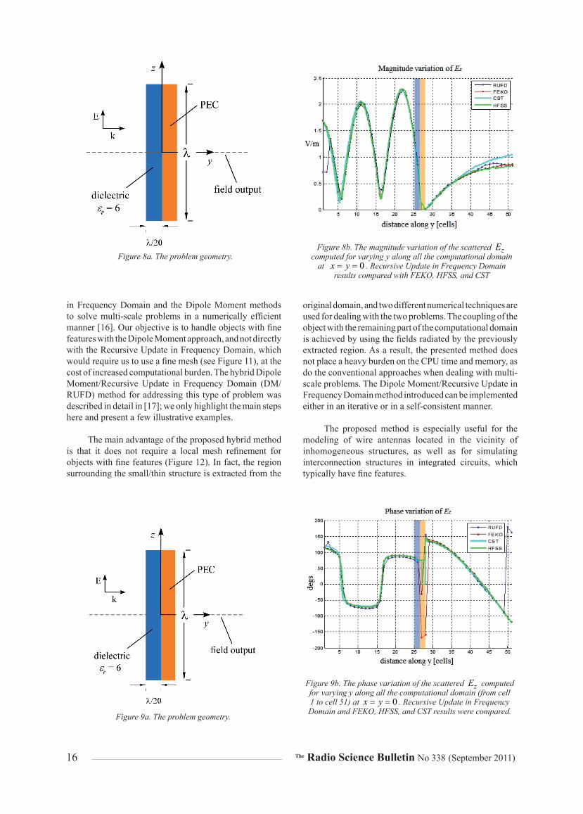
Numerical results for the fields scattered by a dielectric ( 6rε = ) layered conducting plate, 0λ on a side, under normal plane-wave illumination, are presented in Figures 8 and 9. The magnitude and phase variations of the scattered dominant component were computed varying y (expressed in cells) from 1 to 51. Perfectly matched layer (PML) boundary conditions were implemented in the code to terminate the computational domain.
The results were compared against existing commercial codes implementing different numerical techniques: FEKO (MoM), HFSS (FEM), and CST (Finite Integration Technique – FIT). The discretization for all EM solvers was kept around 0 20λ , while all the simulations were carried out using 4 GB RAM and a 3.0 GHz Intel Core 2 Duo processor. The performance benchmarks in terms of memory requirements and running times are displayed in Table 2.
The Recursive Update in Frequency Domain algorithm results were seen to be faster and less memory-demanding when compared to several different commercial solvers, but without a compromise in the accuracy. Furthermore, the Recursive Update in Frequency Domain almost always yielded more stable and accurate results than the other solvers.
3.3.4.Dipole.Antenna
For the last example, we considered a radiation-type problem, as opposed to the scattering problems we have
discussed thus far. We analyzed a dipole antenna, shown in Figure 10a. Since this was a radiation-type problem, it was natural to use the total-field formulation in the context of the Recursive Update in Frequency Domain. The problem was solved in this manner, and the results are compared with FEKO in Figure 10b. The Recursive Update in Frequency Domain results were found to be the more accurate of the two.
3.4.Observations
As alluded to in Section 3.2, the Recursive Update in Frequency Domain algorithm is highly parallelizable. This is because unlike the FEM, it utilizes the difference form of Maxwell’s equations. Since the Recursive Update in Frequency Domain uses Yee’s cell, its meshing requirements are also relatively simple. Moreover, since the Recursive Update in Frequency Domain solves Maxwell’s equations in a recursive manner, without using either iteration or inversion, the problems of dealing with ill-conditioned matrices or constructing robust pre-conditioners are totally avoided. As a frequency-domain solver, it can also handle dispersive media, including plasmonics, relatively easily. To further enhance its performance, we can hybridize it with the Dipole Moment Approach, as shown in the next section. We can also use multi-grid methods or frequency-interpolation schemes to generate the initial values of the fields in the entire computational domain, enabling us to speed up the convergence.
4..The.Hybrid.DM/RUFD.Technique.for.Multi-Scale.
Problems
Direct solution of multi-scale problems by means of conventional computational electromagnetics methods – be they FEM, FDTD, or MoM – is highly challenging, even with the availability of modern supercomputers. This is because of the large number of degrees of freedom introduced when attempting to accurately describe objects with fine features, sharing the computational domain with objects that are large compared to the operating wavelength.
Dealing with multi-scale objects often forces us to compromise the accuracy (relaxing the numerical discretization process when attempting to capture the small-scale features) in order to cope with the limited available resources in terms of CPU memory and time. In this section, we introduce a scheme that combines the Recursive Update
RUFD HFSS FEKO CST
Memory requirements (peak) [MB] 301 447.4 860.5 ph: 449.51vir: 722.84
Simulation time [s] 79.2 132 377.49 215
Table 2. The Recursive Update in Frequency Domain simulation time and memory requirements compared with commercial EM solvers HFSS, FEKO, and CST.
16 The Radio Science Bulletin No 338 (September 2011)
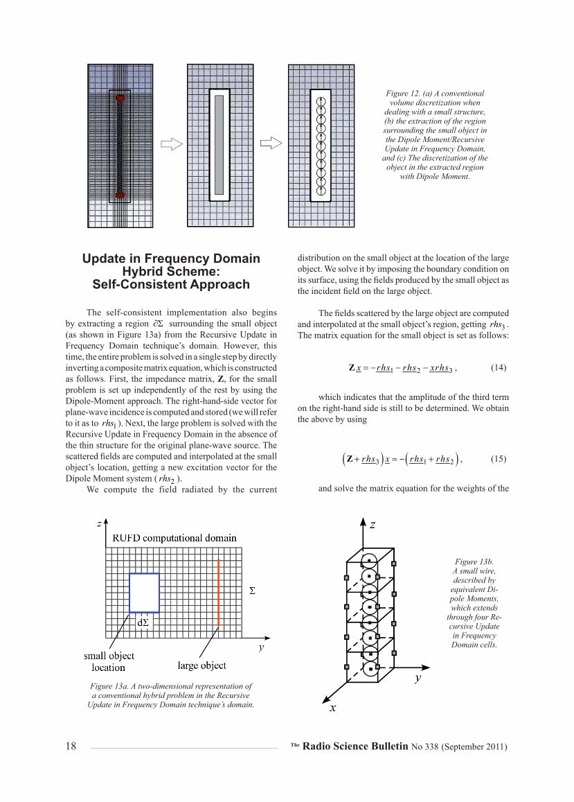
in Frequency Domain and the Dipole Moment methods to solve multi-scale problems in a numerically efficient manner [16]. Our objective is to handle objects with fine features with the Dipole Moment approach, and not directly with the Recursive Update in Frequency Domain, which would require us to use a fine mesh (see Figure 11), at the cost of increased computational burden. The hybrid Dipole Moment/Recursive Update in Frequency Domain (DM/RUFD) method for addressing this type of problem was described in detail in [17]; we only highlight the main steps here and present a few illustrative examples.
The main advantage of the proposed hybrid method is that it does not require a local mesh refinement for objects with fine features (Figure 12). In fact, the region surrounding the small/thin structure is extracted from the
original domain, and two different numerical techniques are used for dealing with the two problems. The coupling of the object with the remaining part of the computational domain is achieved by using the fields radiated by the previously extracted region. As a result, the presented method does not place a heavy burden on the CPU time and memory, as do the conventional approaches when dealing with multi-scale problems. The Dipole Moment/Recursive Update in Frequency Domain method introduced can be implemented either in an iterative or in a self-consistent manner.
The proposed method is especially useful for the modeling of wire antennas located in the vicinity of inhomogeneous structures, as well as for simulating interconnection structures in integrated circuits, which typically have fine features.
Figure 8a. The problem geometry.Figure 8b. The magnitude variation of the scattered zE
computed for varying y along all the computational domain at 0x y= = . Recursive Update in Frequency Domain
results compared with FEKO, HFSS, and CST
Figure 9a. The problem geometry.
Figure 9b. The phase variation of the scattered zE computed for varying y along all the computational domain (from cell 1 to cell 51) at 0x y= = . Recursive Update in Frequency Domain and FEKO, HFSS, and CST results were compared.

The Radio Science Bulletin No 338 (September 2011) 17
4.1..Dipole.Moment/Recursive.Update.in.Frequency
Domain.Hybrid.Scheme:.Iterative.Approach
Both the hybrid and self-consistent implementations (the latter to be described in the following section) begin by extracting from the Recursive Update in Frequency Domain technique’s domain, Σ , a region ∂Σ surrounding the small object (for a two-dimensional representation of the hybrid problem, see Figure 13).
Let us assume that two objects, a large PEC plate and a PEC wire that is small compared to the operating wavelength, are located in the Recursive Update in Frequency Domain computational domain, which is illuminated by a plane-wave source. The hybrid-iteration algorithm begins by solving the large problem in the absence of the thin structure.
The fi elds scattered by the small structure are next derived by using a source excitation comprising of a combination of the original plane wave and the fi elds scattered by the large structure. The small object, which may be PEC, dielectric, or a combination thereof, is treated by using the Dipole Moment approach described in Section 2.3, and a matrix system is constructed. The right-
hand side of this equation is the fi eld incident upon each of the constitutive dipole moments. It is represented by the superposition of both the original plane-wave source and the fi eld scattered by the larger structure. These fi elds are evaluated at the boundary of the extracted region, ∂Σ and are interpolated to obtain the N incident fi elds at each sphere’s location (see Figure 13a for the example of a wire going across four Recursive Update in Frequency Domain cells).
Once the matrix system for the weight coeffi cients of the dipole moments has been solved, we can derive the scattered fi eld (fi rst iteration) inside the domain by superposing all dipole-moment contributions and the previously derived fi elds scattered by the large object. The iteration is subsequently continued by following the same steps as above, except for the fact that at the kth step, the incident plane wave is replaced by the scattered fi eld derived in the ( )1k − th iteration. The process is terminated when numerical convergence has been achieved, i.e., when the difference between the results obtained at the kth and ( )1k −th iteration steps is below a chosen threshold. Figure 14 summarizes the basic steps for the scheme in a fl owchart.
4.2..Dipole.Moment/Recursive.
Figure 11. (a) The conventional solution of a multi-scale problem
comprising a small object that shares the domain with a large
object, and (b) the Dipole Moment/Recursive Update in Frequency
Domain concept.
Figure 10a. The simulated dipole antenna
Figure 10b. The frequency variation of the input reactance using the Recursive Update in Fre-
quency Domain (RUFD) and FEKO.
18 The Radio Science Bulletin No 338 (September 2011)
Update.in.Frequency.Domain.Hybrid.Scheme:..
Self-Consistent.Approach
The self-consistent implementation also begins by extracting a region ∂Σ surrounding the small object (as shown in Figure 13a) from the Recursive Update in Frequency Domain technique’s domain. However, this time, the entire problem is solved in a single step by directly inverting a composite matrix equation, which is constructed as follows. First, the impedance matrix, Z, for the small problem is set up independently of the rest by using the Dipole-Moment approach. The right-hand-side vector for plane-wave incidence is computed and stored (we will refer to it as to 1rhs ). Next, the large problem is solved with the Recursive Update in Frequency Domain in the absence of the thin structure for the original plane-wave source. The scattered fields are computed and interpolated at the small object’s location, getting a new excitation vector for the Dipole Moment system ( 2rhs ).
We compute the field radiated by the current
distribution on the small object at the location of the large object. We solve it by imposing the boundary condition on its surface, using the fields produced by the small object as the incident field on the large object.
The fields scattered by the large object are computed and interpolated at the small object’s region, getting 3rhs . The matrix equation for the small object is set as follows:
1 2 3x rhs rhs xrhs= − − −Z , (14)
which indicates that the amplitude of the third term on the right-hand side is still to be determined. We obtain the above by using
( ) ( )3 1 2rhs x rhs rhs+ = − +Z , (15)
and solve the matrix equation for the weights of the
Figure 13a. A two-dimensional representation of a conventional hybrid problem in the Recursive
Update in Frequency Domain technique’s domain.
Figure 13b. A small wire, described by
equivalent Di-pole Moments, which extends
through four Re-cursive Update in Frequency Domain cells.
Figure 12. (a) A conventional volume discretization when
dealing with a small structure, (b) the extraction of the region surrounding the small object in the Dipole Moment/Recursive Update in Frequency Domain,
and (c) The discretization of the object in the extracted region
with Dipole Moment.

The Radio Science Bulletin No 338 (September 2011) 19
currents x . The final scattered fields are calculated as a weighted superposition of the three contributions as
, ,1 ,2 ,3s f s s sE E E xE= + + . (16)
A flowchart for the steps followed in the self-consistent scheme is displayed in Figure 15. Since the procedure is non-iterative, its running time is more favorable than that of the iterative approach.
While the above scheme works well when only PEC structures are involved as large objects, we need to modify it slightly when the large object is a combination of PEC and dielectric materials. For the details of the modified procedure, the reader is referred to [14].
4.3.Numerical.results
In this section, some numerical results are presented for the two different hybrid techniques. The numerical efficiency over existing methods, both in terms of running
times and memory requirements, is demonstrated via several examples.
4.3.1.PEC.Sheet.in.the.Presence.of.a.3 20λ .Conducting.Wire
Numerical results for the fields scattered by a conducting plate, 0 2λ on a side, under normal plane-wave illumination in the presence of a PEC wire, the length of which is 3 20λ , are presented in Figures 16 and 17. The
Figure 14. The flowchart for the iterative hybrid Dipole Moment/Recursive Update in
Frequency Domain scheme.
Figure 15. The flowchart for the self-consistent Dipole Moment/Recursive Update in Frequency
Domain hybrid scheme.
Figure 16a. The problem geometry.
Figure 16b. The magnitude variations of scattered zE computed for varying y along all the computational domain (from cell 1 to cell 51) at 0x y= = . Recursive Update in
Frequency Domain and FEKO results were compared.

20 The Radio Science Bulletin No 338 (September 2011)
magnitude and phase variations of the scattered dominant component were computed for varying y (expressed in cells) from 1 to 51. The PEC sheet was located at cell 27y = , while the wire was located at a distance of 0.125λ from the sheet, i.e., 2.5 cells away from the sheet along y. A plane-wave source was incident along y, with its E-field vector polarized along z. Absorbing boundary conditions (ABCs) were used to terminate the computational domain for this simulation. The results in the absence and in the presence of the wire were compared against commercial MoM software results. Good agreement with conventional MoM was achieved in this simulation.
4.3.2.PEC.Sheet.in.the.Presence.of.a. 2λ .Conducting.Wire
We next investigated the performance of the hybrid Dipole Moment/Recursive Update in Frequency Domain iterative and self-consistent approaches, both in terms of runtime and accuracy. This was done for the problem of scattering by a PEC sheet that was 1λ on a side, and had a
2λ conducting wire located in close proximity to the sheet. An zE polarized plane wave was normally incident on the structure. The relative distance between the sheet and the wire was the same as in the previous example (Figure 17a). The two hybrid schemes are compared in terms of accuracy against existing commercial codes implementing different numerical techniques – FEKO (MoM), HFSS (FEM), and CST (FIT) – in Figures 18 and 19. The efficiency of the two hybrid methods is compared in terms of running time and memory requirements in Table 3. The cell size was kept as 0 20λ , and the PML boundary conditions were implemented for simulating both hybrid Dipole Moment/Recursive Update in Frequency Domain cases. All the
simulations were carried out on a personal computer with 4 GB RAM and a 3.0 GHz Intel Core 2 Duo processor.
We noted from Figures 18 and 19 that the iterative Dipole Moment/Recursive Update in Frequency Domain hybrid approach provided better performance in terms of accuracy. It was apparent from Table 3 that the self-consistent approach was more efficient. The memory requirements were comparable for the two options.
4.3.3.Dielectric-Coated.PEC.Sheet.in.the.Presence.of.a. 2λ .PEC.Wire
In the following test example, we considered a PEC plate that was coated with 10λ -thick dielectric( 6rε = ), and which shared the computational domain with a 2λ -long conducting wire. These objects were illuminated by a plane wave that propagated along the y axis, with its E-field vector polarized along z (Figure 20). The total field distribution computed by the present approach is compared against commercial codes implementing the MoM (FEKO), the FEM (HFSS), and the FIT (CST) in Figure 21. Note that satisfactory agreement was achieved with HFSS and CST, both in amplitude and in phase (see Figure 21), while the commercial MoM results were not as accurate for this example.
The performance in terms of running time and memory requirements are displayed in Table 4. We also noted from
Figure 17a. The problem geometry.
Figure 17b. The phase variations of scattered zE com-puted for varying y along all the computational domain (from cell 1 to cell 51) at 0x y= = . Recursive Update
in Frequency Domain and FEKO results were compared.
Hybrid DM/RUFDSelf Consistent
Hybrid DM/RUFDIterative
Memory requirements (peak) [MB] 483 481
Simulation time [s] 172.3 601
Table 3. The hybrid Dipole Moment/Recursive Update in Frequency Domain iterative and self-consistent implementa-
tions compared in terms of simulation time and memory requirments
(the cell size was 20λ , and PML boundary conditions were used).

The Radio Science Bulletin No 338 (September 2011) 21
this table that the Hybrid Dipole Moment/Recursive Update in Frequency Domain code performed better than either CST or HFSS, both in terms of memory and running time. Although the simulation time for the Recursive Update in Frequency Domain was comparable to that of the MoM code, the latter did not generate accurate results for this case, as noted earlier. We believe that the inaccuracies stemmed from the difficulty with the MoM technique when dealing with thin, inhomogeneous structures. As we also saw from Table 4, the finite methods paid a toll in terms of increased memory and running times, owing to the use of fine meshes when dealing with multi-scale problems.
4.4..Enhancements.of.the.Dipole.Moment.and.Recursive.Update.in.Frequency.Domain.Techniques
I• Applies novel techniques to deal with problems
at low frequencies.
• Enhances the convergence of the recursive update scheme by applying signal-processing techniques to the time signature.
• Uses the above signal-processing techniques and derives
the solution for multiple frequencies in a single run, enhancing the computational efficiency of the original Recursive Update in Frequency Domain algorithm quite significantly in the process.
• Handles dispersive media, as well as those with negative ε and µ as long as the material can be represented by using either Debye or Drude models.
To illustrate the numerical efficiency of the νCFDTD relative to the Recursive Update in Frequency Domain, we considered the waveguide filter shown in Figure 22, which is a high-Q structure. Table 5 compares the number of iterations required to solve the waveguide filter shown in Figure 22. The time advantage of νCFDTD over Recursive Update in Frequency Domain was evident.
The results of these embellishments to the Dipole Moment and Recursive Update in Frequency Domain algorithms will be reported in future publications.
Figure 18a. The problem geometry.
Figure 18b. The magnitude variation of scat-tered zE computed for varying y along all the computational domain (from cell 1 to cell 51).
Figure 19a. The problem geometry.
Figure 19b. The phase variation of scattered zE : the results of the hybrid Dipole Moment/Recursive Update in Frequency Domain iterative and self-consistent were com-
pared with commercial MoM, FEM, and FIT solvers.

22 The Radio Science Bulletin No 338 (September 2011)
5..Conclusion
In this work, we have introduced some novel concepts in computational electromagnetics (CEM) that deviate from the conventional MoM, both in terms of their formulation as well as their solution of radiation and scattering problems. We have shown how MoM-type problems can be formulated by using Dipole Moments, without the use of Green’s functions. We have argued that the Dipole Moment formulation offers us a way to formulate the computational electromagnetics problems involving PEC as well as dielectric objects in a uniform manner. The Dipole Moment formulation also mitigates the so-called low-frequency problem, and is well suited for handling multi-scale problems.
The Recursive Update in Frequency Domain approach, which has the versatility of the FDTD method, may be viewed as the frequency-domain version of the FDTD algorithm. However, unlike the FEM, it does not rely on the solution of a matrix equation, either directly or iteratively, but generates the solution via a recursive procedure, instead. We have shown how the Dipole Moment and Recursive
Update in Frequency Domain algorithms may be combined to accurately and efficiently solve multi-scale problems. The performance of the resulting hybrid scheme has been found to be superior to those of some of the well-known and widely used computational electromagnetics codes, both in terms of accuracy and computational efficiency. Enhancements to the basic Dipole Moment and Recursive Update in Frequency Domain algorithms – such as for instance the νCFDTD and its hybridization with Dipole Moment – which would further enhance their performances are currently being actively investigated. The preliminary outlook appears to be quite promising, indeed.
6..References
Hybrid DM/RUFD Self Con-
sistentFEKO CST HFSS
Memory require-ments (peak) [MB] 348 690.6 ph: 1590
vir: 1910 1680
Simulation time [s] 260 284.12 1565 1861
Table 4. The performance of the hybrid and self-consistent Dipole Moment/
Recursive Update in Frequency Domain implementation, compared with FEKO, CST, and HFSS in terms of the simula-
tion time and memory requirements (the discretization was 20λ ).
Figure 20a. A two-dimensional cut of the problem geometry.
Figure 20b. A three-dimensional repre-sentation of the problem geometry
RUFD νCFDTD
Required Number of Iterations 37500 > 6000
Table 5. The performance of νCFDTD in terms of the required number of iterations compared with the
Recursive Update in Frequency Domain.

The Radio Science Bulletin No 338 (September 2011) 23
1. B. T. Drai ne and P. J. Flatau, “Discrete-Dipole Approximation for Scattering Calculations,” J. Opt. Soc. Am. A, 11, April 1994, pp. 1491-1499.
2. R. F. Harr ington, Field Computation by Moment Methods, New York, The Macmillan Company, 1968.
3. R. Mittra, Computer Techniques for Electromagnetics, New York, Hemisphere Publishing Corporation, 1987.
4. A. F. Pete rson, S. L. Ray, and R. Mittra, Computational Methods for Electromagnetics, New Jersey, IEEE Press, 1997.
5. R. Mittra, K. Panayappan, C. Pelletti and A. Monorchio, “A Universal Dipole-Moment-Based Approach for Formulating MoM-Type Problems without the Use of Green’s Functions,” Proceedings of the European Conference on Antennas and Propagation 2010, Barcelona, April 2010.
6. R. Harring ton, Time-Harmonic Electromagnetic Fields, Pis-cataway, NJ, IEEE Press, 2001.
7. J. Bringui er, Multi-scale Techniques in Computational Elec-tromagnetics, PhD dissertation, Pennsylvania State University, 2010.
8. E. C. Jord an and K. G. Balmain, Electromagnetic Waves and Radiating Systems, Upper Saddle River, NJ, Prentice Hall, 2001.
9. C. Pellett i, R. Mittra, K. Panayappan and A. Monorchio, “A Universal and Numerically Effi cient Method of Moments Formulation Covering a Wide Frequency Band,” IEEE Inter-national Symposium on Antennas and Propagation and USNC/URSI National Radio Science Meeting, Spokane, Washington, July 3-8, 2011.
10. E. Lucent e, A. Monorchio, and R. Mittra, “An Iteration-Free MoM Approach Based on Excitation Independent Characteristic Basis Functions for Solving Large Multiscale Electromagnetic Scattering Problems,” IEEE Transactions on Antennas and Propagation, AP-56, April 2008, pp. 999-1007.
11. S. J. Kwo n and R. Mittra, “Impedance Matrix Generation by Using Fast Matrix Generation (FMG) Technique,” Microwave and Optical Technology Letters, 51, January 2009, pp. 204-213.
12. C. Pfl aum and Z. Rahimi, “An Iterative Solver for the Finite-Difference Frequency-Domain (FDFD) Method for Simula-tion Of Materials With Negative Permittivity,” Numer. Linear Algebra Appl., 18, 4, August 2011, pp. 653-670.
13. K. S. Yee , “Numerical Solution of Initial Boundary Value Problems Involving Maxwell’s Equations in Isotropic Media,” IEEE Transactions on Antennas and Propagation, AP-14, 3, May 1966, pp. 302-307.
14. G. Mur, “Absor bing Boundary Conditions for the Finite-Difference Approximation of the Time-Domain Electromag-netic Field Equations,” IEEE Transactions on Electromagnetic Compatibility, 23, 3, 1981, pp. 377-382.
15. J. P. Ber enger, “Three-Dimensio nal Perfectly Matched Layer for the Absorption of Electromagnetic Waves,” J. Comp. Phys., 127, 1996, pp. 363-379.
16. C. Pellet ti, K. Panayappan, R. Mittra and A. Monorchio, “On the Hybridization of RUFD Algorithm with the DM Approach for Solving Multiscale Problems,” Proceedings of the 20th
Figure 21b. The phase variations of the fi nal total fi elds along the y axis. The results computed through the modi-fi ed self-consistent hybrid scheme were compared with
FEKO, HFSS, and CST.
Figure 21a. The magnitude variations of the fi nal total fi elds along the y axis. The results computed through the modifi ed self-consistent hybrid scheme were compared
with FEKO, HFSS, and CST.
Figure 22. A waveguide fi lter.

24 The Radio Science Bulletin No 338 (September 2011)
International Symposium on EM Theory, Berlin, Germany, August 2010.
17. C. Pelletti, Numerically Efficient Techniques for Electromag-netic Scattering Calculations in the Frequency Domain, PhD dissertation, University of Pisa, 2011.

The Radio Science Bulletin No 338 (September 2011) 25
On a Technique for Supplying Power to Global Radio Relays for High-Altitude Platforms by Means
of Microwave Beams
R.B. Vaganov I.P. Korshunov
E.N. Korshunova A.D. Shatrov
Abstract
Wireless power transmission (WPT) represents a promising direction in engineering that first of all is associated with the use of radio-physical techniques. Wireless power transmission is based on a double-step conversion of electric power: first, dc energy is converted into microwave-field energy that is transmitted as a wave beam to a rectenna; and second, the microwave-field energy is converted back into dc energy. Wireless-power-transmission systems are of interest for power transmission from ground-based sources of energy to air-based objects, such as high-altitude platforms (HAPs) for radio relays, as well as to inaccessible terrestrial objects. Wireless-power-transmission systems have no alternative as a means for electric-power transportation from space solar stations (SPSs) to Earth.
1..Introduction
One of the key tasks in wireless power transmission is shaping a wave beam. The field at the output of an antenna is determined by its amplitude and phase distributions. The beam-transmission losses, transverse beam dimension, as well as other characteristics of the beam, are ultimately determined by these distributions.
Since wireless-power-transmission systems should transmit large amounts of electric power [1, 2], there is a risk of the harmful effects of this radiation on the environment, particularly on the biosphere and the ionosphere. Experimental investigations of [3] have allowed one to assess two “bottleneck” factors:
Roald Vaganov, Igor Korshunov, Evgenija Korshunova, and Alexander Shatrov are with the V. A. Kotelnikov Institute of Radio Engineering and Electronics, Russian Academy of Science, 1 Vvedensky sq 141 190 Fryazino, Moscow region, Russia; Tel: 496 56 52 440 (IK); Fax: 495 702 95 72; E-mail: [email protected]; [email protected]; [email protected]; [email protected].
1. The maximum admissible beam intensity, ionp , that does not disturb the stability of the ionosphere.
2. The maximum intensity of diffraction background, near the rectenna’s edge.
Traditionally, it is assumed that one should employ a Gaussian-distributed field to attain the maximum transmission factor (TF) [3, 4]. However, as we showed in [5], this distribution does not ensure the transmission of large power levels, because the utilization factors (UFs) of the antenna and rectenna are small. Moreover, in this case, the maximum field intensity on the rectenna may exceed the value ionp . In this respect, a Rayleigh-distributed field turns out to be preferable, because it provides for the transmission of higher power compared with the Gaussian field for admissible values of ionp and ( )max
diffp . The theoretical analysis, conformed to wireless power transmission-space solar station systems, was accomplished in [5].
2..Formulation.of.the.Problem
Let us consider a wireless-power-transmission system as illustrated in Figure 1. The system consists of a transmitting antenna and a rectenna, with respective radii of a and b . The wave beam creates a diffraction field in the rectenna plane, the main part of which reaches the rectenna’s aperture. Behind the rectenna’s aperture, a diffraction background field is formed.
The Fresnel parameter is 21c ka L= , where
2k π λ= is the wavenumber, λ is the wavelength, and 21L km is the distance between the rectenna and the
antenna. The generalized Fresnel parameter,

26 The Radio Science Bulletin No 338 (September 2011)
kabcL
= , (1)
does not exceed a value of 10.
The main characteristics of wireless-power-transmission systems are the microwave power, W , received by the rectenna, and the transmission losses. There are two additional conditions. The first of these restricts the maximum wave-beam intensity in the Earth’s ionosphere to the value 2200 W/mionp ≈ , and the second condition restricts the field intensity near the rectenna’s edges to the value ( ) 210 W/mmax
diffp ≈ [3].
The power received by the rectenna can be expressed by the complicated function
( ) ( )1 1, , , , ,W F a b L U r rλ φ= Φ , (2)
where ( ) ( )1 1,U r r φΦ is the amplitude-phase distribution of the radiated field with respect to the radial (
1r ) and azimuthal (φ ) coordinates. Usually, the amplitude distributions are described by Hermite-Laguerre functions, and the phase distributions have the form of a squared relationship of 1r at that phase-front curvature equal to LThe maximization of W is generally a multi-parameter problem. However, this problem is simplified when the values L , λ , and (for instance) b are fixed [6].
When choosing specific geometrical characteristics of a wireless-power-transmission system, we take the generalized Fresnel parameter, c, to be 2π , and the wavelength, λ , to be 5.2 cm. For the Gaussian field distribution, this corresponds to TF 0.99rct radW W= >Here, rctW is the power received by the rectenna, and
radW is the power radiated by the antenna. Then, from Equation (1), we obtain
3 210 m2cLab λπ
= . (3)
Using estimated dimensions for flying vehicles, the altitude of their trajectory, and the wavelength, we set 2 25b = m. Then, according to Equation (3), we obtain 2 170a = m. For the given geometry of a wireless-power-transmission system, the wave beam passing from the antenna to the rectenna thus turns out to be convergent, as is shown in Figure 1. As opposed to this situation, the wave beam coming to the rectenna turns out to be divergent for wireless power transmission-space solar station systems [5].
The aim of this study is the development of an approach that enables one to choose an optimum distribution of the field to feed high-altitude platforms using a wireless-power-transmission system. We analyze what parameters of the Gaussian and Rayleigh field distributions allow one to transmit the maximum power from the antenna to a rectenna of given dimensions, under the condition that the maximum field intensity on the rectenna does not exceed the admissible value, ionp .
3..Transmission.of.the.Maximum.Possible.Power.Level.for.a.Given.Architecture.of.the.Wireless-Power-Transmission.System
The transmission factor is not an exclusive feature that specifies wireless-power-transmission system efficiency. It is known [7] that the maximum possible level of a rectenna’s power is an important attribute. In the section, we look for the parameters 1σ and 2σ of the Gaussian (G) and Rayleigh (R) field distributions that produce the maximum possible power level for a rectenna of dimensions of 2r b and
2c π= (see Equation (3)).
The Gaussian and Rayleigh axisymmetric field distributions over the antenna may be represented as follows:
( )
2 22 1
G 1 0 1 1exp2
kaU U iLρ
ρ σ ρ
= − −
, (4)
( ) ( )2 2
2 1R 1 2 1 2 1exp
2kaU B i
Lρ
ρ σ ρ σ ρ
= − − , (5)
where 1 r aρ = , 1σ and 2σ are truncation factors,
( )0
0
12
maxantU p
Z= ,
Figure 1. A diagram of the formation of a microwave beam in the wireless power transmission-system.

The Radio Science Bulletin No 338 (September 2011) 27
( ) ( ) ( )2 2
0
12 exp 1 22
maxantB p
Zσ σ= ,
are the field magnitudes, ( )maxantp is the maximum field
intensity at the antenna, 0 120Z π= ohm is the free-space impedance, and 1i = − .
The field-intensity distributions for the Gaussian and Rayleigh wave beams are illustrated in Figures 2a and 2b, respectively. It should be noted that the Rayleigh distribution conforms with the so-called the modified mode, representing the quadrature superposition of the sine and cosine components of the 10TEM eigenmode of a quasi-optical system similar to a laser resonator [5]. The eigenmode fields may be represented in the following form:
( )2 2
010 1 2 2, 2 2 exp 2r r rU r L iϕ φ
ω ω ω
= × − − ,
where 01L is the Laguerre polynomial, ω is the
specific transverse dimension of the field, and r and φ are
radial and azimuthal coordinates [8]. The modified-mode intensity distribution is
( )22 2
( ) 0110 2 2, 2 2 exp 2quadr r r rV r Lϕ
ω ω ω
= −
. (6)
The field of the mode may be plane polarized. In this case, the dependence of the phase on the azimuthal angle has the form ( )exp iφ− , i.e., the field contains sine and cosine components in quadrature. Photographs of the intensity distributions over laser-beam cross-sections, generated by a He-Ne laser, 10TEM sin− , 10TEM cos− , and 10TEM quadr− , are presented in Figures 3a, 3b, and 3c, respectively. Note that the cosine and sine components – which are shown in Figures 3a and 3b, respectively – are linearly polarized with identical (vertical) orientations of the vector, E
. The field of the quadrature superposition, shown in Figure 3c, is also linearly polarized.
As an additional criterion in the consideration, we use the field intensity at the edge of the rectenna, or in
Figure 2a. The three-dimensional field-intensity dis-tributions on the rectenna for the Gaussian beam.
Figure 2b. The three-dimensional field-intensity dis-tributions on the rectenna for the Rayleigh beam: Dx
and Dy are the quadrupole sensors.
Figure 3a. Photographs of the field distributions over the laser-beam
cross sections for the laser eigenmode 10TEM sin− .
Figure 3b. Photographs of the field distributions over the laser-beam
cross sections for the laser eigenmode 10TEM cos− .
Figure 3c. Photographs of the field distributions over the laser-beam
cross sections for the laser modified mode 10TEM quadr− .

28 The Radio Science Bulletin No 338 (September 2011)
the diffraction lobe nearest to the rectenna’s edge. For definiteness, assume that the maximum field intensity directly beyond the rectenna is the same for both distributions.
An admissible microwave field intensity that does not disturb the ionosphere (in implied thermal effects) is
2200 W/mionp ≈ [3]. An estimated altitude of a high-altitude-platform orbit (~21 km) is about four times less than the lower edge of the ionosphere. Therefore, even if the microwave beam misses the rectenna, its maximum intensity at an altitude of 80 km falls off by a factor of 16. If we thus take 2200 W/mionp = , the admissible intensity on the rectenna located at an altitude of 21 km, is
( ) 216 3 kW/mmaxrct ionp p . The dependence on altitude of
the maximum intensity distributions along the longitudinal axis of the microwave beams will be considered later.
We calculate the field-intensity distributions over a rectenna’s plane in the quasi-optical approximation by analogy with the calculations in [5-7]:
( ) ( ) ( )
212
1 2 1 1 1 0 1 2 1 10
, ,G GV c U J c dσ ρ σ ρ ρ ρ ρ ρ
= ∫ , (7)
( ) ( ) ( )21
2R 2 2 1 R 2 1 1 1 2 1 1
0
, ,V c U J c dσ ρ σ ρ ρ ρ ρ ρ
= ∫ , (8)
where 1 1r aρ = and 2 2r aρ = are the normalized radial coordinates in the antenna and rectenna planes, and ( )nJ is the Bessel function of nth order.
From Equations (7) and (8), let us calculate the following functions for the Gaussian and Rayleigh field distributions:
1. The field intensities at the edge of the rectenna or in the diffraction lobe nearest to the rectenna edge 2r b≥ :
( ) ( )
2( )
1 1 2,b
diffG G rGV Vσ γ σ ρ
≥= , (9)
( ) ( )
2( )
2 2 2,b
diffR R rRV Vσ γ σ ρ
≥= , (10)
where
( )
( )
1,0
maxrct
GG
pV
γσ
= , (11)
(
( )2 2,
max)rct
R maxR
p
Vγ
σ ρ=
,
and ( )2maxρ is the radial coordinate that corresponds to the
maximum intensity.
2. The maximum power received by the rectenna is
( ) ( )21 1 2 2 2
0
2 ,b a
G G GW b V dσ π γ σ ρ ρ ρ= ∫ , (12)
( ) ( )22 2 2 2 2
0
2 ,b a
R R RW b V dσ π γ σ ρ ρ ρ= ∫ . (13)
3. The utilization factors of the antenna are
( ) ( )1
21 1 1 1
0
2G GU dκ σ ρ ρ ρ= ∫ , (14)
( ) ( )1
22 1 1 1
0
2R RU dκ σ ρ ρ ρ= ∫ . (15)
The transmission factors of the considered wireless-power-transmission system are determined in the following form:
( )( )
( )1
2( )
Gant
G
Rant
R
WW
WW
η σ
η σ
=
, (16)
where
( ) ( )2( ) 20 1
antG GGW a Uγ π κ σ= , (17)
( ) ( )2( ) 22 2
antR RRW a Bγ π σ κ σ= . (18)
All of the results mentioned below were obtained as numerical solutions of Equations (7), (8) and (12)-(18). Some simulated experiments are planned to be carried out in the optical wavelength range, by analogy with an experiment in [8]. In the experiments, the efficiency of the Gaussian and Rayleigh field distributions will be investigated.

The Radio Science Bulletin No 338 (September 2011) 29
Let us consider some results of the numerical solutions. In Figure 4, curve 1 represents the power, ( )1GW σ , that falls on the rectenna’s aperture as a function of the truncation factor, 1σ , for the Gaussian distribution of the radiated field (the left axis). Curves 2 and 3 represent the field intensity at the edge of the rectenna, ( )( )
1diff
GV σ , and the antenna utilization factor, ( )1Gκ σ , respectively (the right axis).
In Figure 5, curve 1 represents the power, ( )2RW σthat falls on the rectenna’s aperture as a function of the truncation factor, 2σ , for the Rayleigh distribution of the radiated field (the left axis). Curves 2 and 3 represent the field intensity at the edge of the rectenna, ( )( )
2diff
RV σ , and the antenna utilization factor, ( )2Rκ σ , respectively (the right axis).
Let us suppose that the field intensity near the rectenna’s edge is 2~ 10 W/m for both the Gaussian and Rayleigh field distributions. Under this condition, from Figures 4 and 5 we obtained ( )
1 3.6condσ and (c )2 2.3ondσ It is significant
that the maximum field intensity over the rectenna was (max) 3 216 3 10 W/mrct ionp p × .
Figure 6 shows the absolute values of the power received by the rectenna as a function of its radius. One can see that the magnitudes of the rectenna power for a rectenna radius of 2 12.5r = m were ( )
G 1 300condW σ kW and ( )
R 2 600condW σ kW for the Gaussian and
Rayleigh field distributions, respectively.
Figure 4. The power in the rectenna’s plane, ( )1GW σ , the field intensity at the rectenna’s edge,
( )( )1
diffGV σ , and the Gaussian utilization factor,
( )1Gκ σ , for the Gaussian radiated field.
Figure 5. The power in the rectenna plane, ( )2RW σ , the field intensity at the rectenna’s edge,
( )( )2
diffRV σ , and the Rayleigh utilization factor,
( )2Rκ σ , for the Rayleigh radiated field.
Figure 6. The power in the rectenna’s plane for the Gaussian and Rayleigh
distributions of the radiated field.
Figure 7. The intensity distributions in the rectenna’s plane for the Gaussian and
Rayleigh radiated fields.

30 The Radio Science Bulletin No 338 (September 2011)
Figure 7 shows the field intensity in the rectenna’s plane for the Gaussian and Rayleigh distributions. These distributions correspond to the values of the transmission factors, which were determined in Figures 4 and 5, respectively. One can see that for equal maximum intensities of 3 23 10 W/m× in the main lobes of the Gaussian and Rayleigh distributions, the diffraction background field for these distributions was roughly the same ( 210 W/m≈ ).
The transmission factors of the considered Gaussian and Rayleigh distributions for the above-mentioned values of ( )
1condσ , ( )
2condσ were
( )1 0.995condη σ = and ( )
2 0.984condη σ = .
The calculations were performed in conformance with Equations (16)-(18).
Let us consider the dependence of the maximum intensity distributions along the longitudinal axis of the microwave beams on the altitude, h . The dependences of the transverse microwave-beam dimensions for the Gaussian and Rayleigh distributions on the altitude, h , may be determined as [8]
( )( ) ( )
( )
0.5222 20 1,2
, 22 20 1,2
G RL h L h k
hk L
ω σω
ω σ
− − =
, (19)
where ( ) 0.50 1,22aω σ
−= is the specific transverse
dimension of the field on the antenna. The dependences of the maximum intensity distributions along the longitudinal axis of the microwave beams on the altitude, h , may then be expressed as
( )( )
2( ) 0
, , 2,
antG R G R
G RV h V
hω
ω= , (20)
where ( )2( )0
antGV U= , ( ) 2( )
2ant
RV B σ= . The dependences are shown in Figure 8. It was obvious from Figure 8 that the maximum field intensities for the Gaussian and Rayleigh distributions below the altitude of 10 km did not exceed the value 2130 W/m .
4..Conclusions
The Rayleigh distribution of the radiated field is thus more preferable compared to the Gaussian distribution for meeting the goal set in the formulation of the problem (to attain the maximum received power). Indeed, the distribution provides a power transmission twice as large as the Gaussian distribution for the same diffraction background. In addition, the Rayleigh field intensity on the antenna turns out to be ( ) ( )
2 1 1.8cond condR Gκ σ κ σ
times less than the appropriate Gaussian field intensity.
We should stress that for a Gaussian driving field, it is not expedient to increase the transmitted power, say, by increasing 1σ (see Figure 4). Indeed, in this case, the gain in the transmitted power amounts to a few percent, whereas the diffraction background increases significantly, and the antenna-utilization factor decreases. In other words, the maximum intensity of the radiated field on the antenna increases still more.
The Rayleigh field distribution allows for a more-efficient use of the rectenna’s surface, due to the fact that the received field in the rectenna’s plane is more uniform than that in the case of the Gaussian distribution. Another advantage of the Rayleigh distribution is that it allows for the precise alignment of the wave-beam axis with the rectenna’s center. This is illustrated in Figure 2b. Here, quadrupole sensors D ,Dx y are located in the central zone of the rectenna, where the rectenna’s field intensity is close to zero. At the same time, using the data in Figure 7, one can easily find that the relative magnitude of the field intensity gradient is about
( )( ) [ ]2 0.5
2 1
2 21 dm
r
R
R
d V rdr V r
− m
for sensor base dimensions of 2 0.03...0.05r b . In other words, a differential sensor with a base of 0.5 m displaced by 1 dm along, say, the x axis can detect a 10%
Figure 8. The dependence on the altitude of the intensity distributions over the longitudinal axis of
the microwave beams.

The Radio Science Bulletin No 338 (September 2011) 31
variation in the microwave power. One can use the central elements of the rectenna array for such sensors.
In the analysis carried out above, all the numerical calculations applied to a quite-specific wireless-power-transmission geometry. The choice of the antenna and the rectenna’s dimensions were conventional; the dimensions may be different: it is important that the relation of Equation (3) should be satisfied.
We have considered the conditions for transmitting of the maximum possible microwave power from an Earth-based terminal to the remote spatial object. When the required rectenna power level is smaller than the maximum level, the maximum antenna field intensity should be reduced.
According to [3], the system considered above is intended for power transmission by a microwave beam with a wavelength of 5.2λ cm. Recently, some other versions of similar systems with shorter wavelengths have been the subject of intense, wide speculation in the literature. Note that when using wavelengths of 6 mm, the antenna and rectenna dimensions decrease by a factor of three compared to the system considered in this paper. If one may suppose that the former rectenna’s dimension are kept, i.e. 2 25b =m, then the antenna’s dimension comes to 2 21a m.
5..References
1. J. Gavan, S. Tapuchi, and D. Grace. “Concepts and Main Ap-plications of High-Altitude-Platform Radio Relays,” Radio Science Bulletin, No. 330, September 2009, pp. 20-31.
2. J. Gavan and S. Tapuchi, “Microwave Wireless-Power Trans-mission to High-Altitude-Platforms Systems,” Radio Science Bulletin, No. 334, September 2010, pp. 25-42.
3. URSI, “White Paper on a Solar Power Satellite. URSI Inter-Commission Working Group on SPS,” Ghent, Belgium, URSI, 2006, pp. 51.
4. I. P. Korshunov and V. E. Lyubchenko, “International and Na-tional Projects of Development of the Space Satellite Systems for Wireless Power Transmission by Means of Microwaves,” Fiz. Voln. Protsessov Radiotekh. Sist., 9, 3, 2006, pp. 6-18.
5. R. B. Vaganov, B. G. Klevitskii, I. P. Korshunov, E. N. Kors-hunova, and A. D. Shatrov, “On the Potential Energy Output of a System Transporting the Electromagnetic Energy by Means of Microwave Beams” J. Commun. Technol. Electron, 54, 12, 2009, pp. 1366-1371.
6. R. B. Vaganov, B. G. Klevitskii, I. P. Korshunov, E. N. Kors-hunova, and A. D. Shatrov, “Transport of Microwave Energy from a Solar Power Plant to the Earth and from the Earth to Low-Orbit Objects,” J. Commun. Technol. Electron, 55, 11, 2010, pp. 1246-1125.
7. R. B. Vaganov, “Maximum Power Transmission between Two Apertures with the help of Wave Beam,” J. Commun. Technol. Electron., 42, 4, 1997, pp. 397-492.
8. H. Kogelnik and T. Li, “Laser Beams and Resonators,” Pro-ceedings of the IEEE, 54, 10, pp. 96-110.
9. R. B. Vaganov, B. G. Klevitskii, I. P. Korshunov, E. N. Kor-shunova, S. S. Shaposhnikov, and A. D. Shatrov, “Formation of Axisymmetric Wave Beams with Suppressed Diffraction Lobes,” J. Commun. Technol. Electron., 48, 9, 2003, pp. 983-989.

32 The Radio Science Bulletin No 338 (September 2011)
COMMISSION A
Triennial Reports Commissions
This report was prepared by Dr P. Banerjee, Commission A Chair 2008-2011.
In the triennium 2008-2011, Commission A has been active through the following events. Commission A deals with a wide range of scientific activities covering measurement related issues in all electrical and electronics parameters, components and devices.
New terms of reference were worked out to make them quite relevant to emerging developments and strategies. This is also aimed at to make the commission activities more relevant to the society and to stimulate more participants. Terms of reference of Commission A has been modified in the last GA 2005. But afterward a through review has been made through various discussions and the new terms of reference have emerged.
The commission promotes research and development of the field of measurement standards and physical constants, calibration and measurement methodologies, improved quantification of accuracy, and traceability, and the inter-comparison of such. Areas of emphasis are:
(a) the development and refinement of new measurement techniques and calibration of standards
(b) primary standards, including those based on quantum phenomena, and the realization and dissemination of time and frequency standards
(c) characterization of the electromagnetic properties of materials, physical constants, and the properties of engineered materials, including nanotechnology
(d) methodology of electromagnetic dosimetry and measurements for health diagnostics, applications, and biotechnology: including biosensing
(e) measurement validity in advanced communication systems and other applications
The commission fosters accurate and consistent measurements needed to support research, development and exploitation of electromagnetic technologies across the spectrum and for all commissions.
These may further be evolved in due course of time keeping space with the rapid advancement in radio science and communication and the related technologies
During this triennium Long Range Planning Committee (LRPC), under the chairman ship of Prof. P. Cannon, was quite active through discussions ( via tele-conferences and emails) with respective chairs of commissions. The following aspects have been emphasized
for Commission A. The emerging topics of the commission are identified as a. developments of quantum standards b. GNSS timing systems c. nano-metrology and d. effect of em waves on eco-system (man and environments). The primary technical domain of commission is obviously instruments and measurement. This should give emphasis on social aspects of science and technology and also on navigation. The secondary areas are well recognized as antennas, propagation, electromagnetic compatibility, electron device and system, laser & electron optics, magnetic, microwave theory & techniques and optics & optical technology.
The preparation of the session of the 2011 General Assembly in Istanbul was one of the major activities. Organization of technical programme and Interactions and discussions were initiated to work out topics tentatively since early 2009.
Recent decade has seen tremendous progress in optical clocks. With the availability of ultra stable clocks in different parts of the world separated by few thousands of kilometers, it has become a challenge to compare their performances with a short span of time. Continusous efforts are being put by many laboratories to make the time scale more stable and more accurate. The state-of-the-art in antenna measurements, with an emphasis on both near-field measurements and remote measurements have made many strides in recent years, with new fast methods. New communications technology leads to the inevitable need for new measurement techniques to properly characterize the systems. Recent advances in radio astronomy technology enable significant progress in the timing precision that will cumulate in the extraordinary experiments possible with the future Square Kilometer Array (SKA).
Noting the above facts, some emerging topics have been focused in the technical session of the Istanbul General Assembly. Few speakers who are eminent in respective field could be consented to give talks. Based on the responses, sessions covering following topics have been finalized.
These are Low Noise Microwave Generation, Fractals Design and Measurement, Time Scale, EM Materials, Antenna Measurement, Pulsar Timing and Time Transfer, Optical Frequency Metrology and Communication Metrology. Many of the above topics were of common interest for few other commissions. Some joint Commissions could be arranged and a good response from the delegates with contributed papers was received. Respective session-conveners took special efforts to encourage the concerned experts for submission of papers and participation. With the help of very enthusiastic session conveners, the overall

The Radio Science Bulletin No 338 (September 2011) 33
COMMISSION C
technical programme of Commission A of the Istanbul general assembly took a nice shape.
A tutorial talk on a special emerging topic of “Single Electron Tunneling” was given by Dr. Stephen Giblin of NPL UK. Topic was fundamental in nature, to be precise, it was related to the redefinition of the unit of electric current by counting number of electrons per second.
Commission A has given notional support in the last three years to organization of many conferences held across the world - particularly those have some connection with the activities related to Commission A. APRASC 2010 which was held in Japan had given good emphasis on the topics related to Commission A. It was well attended by experts of commission A.
The issue related to the continuation of “Leap Second” has been an important international debate. International Telecommunication Union (ITU) is supposed to decide on this based on Recommendations ITU_R_TF.460-6. Experts of commissions A and respective national representatives contributed substantially to discussions on the continuation of “Leap Second”. These discussions will help in making the final decision on this long pending issue.
For the election of New Vice, requests have made to national committees for nomination of candidates. Two nominations received e.g. Dr. Y. Koyama, NICT, Japan and Dr. D. Matsakis, USNO, USA. After voting Dr. Koyama was elected as New vice chair of the commission A for the next three years.
This report was prepared by Takashi Ohira, Commission C Chair 2008-2011.
1..Scope.of.Activities
Commission C promoted research and development in:(a) Radio-Communication and Telecommunication
systems;(b) Spectrum and Medium Utilisation;(c) Information Theory, Coding, Modulation and Detection;(d) Signal and Image Processing in the area of radio science.
The design of effective radio-communication systems included scientific, engineering and economic considerations. The commission emphasised research into scientific aspects, and provides enabling technologies to other areas of radio science.
2..International.Events..Sponsored.or.Cosponsored.by.
Commission.C
2.1.International.Symposium.on.Signal.System.and.Electronics.
“ISSSE.2010”
Sponsors: Commissions C and DVenue: Nanjing, ChinaDate: Sept. 16-19, 2010Chair: Prof. Wei Hong, South East University, China
ISSSE2010 was held in Mandarin Garden Hotel, Nanjing, China on September 16-19, 2010. This symposium is held every three years, and is organized under the
guidance and with sponsorship of the international steering committee of the URSI Commissions C and D. It has a long tradition of moving around the world; the last three previous conferences were held in Tokyo (Japan 2001), Linz (Austria 2004) and Montreal (Canada 2007). This event is co-sponsored by Southeast University, IEEE MTT-S, Antenna Society of Chinese Institute of Electronics (CIE), Microwave Society of CIE, IEEE Nanjing Section. ISSSE2010 began with keynote speech: Progress in antennas and propagation for body area networks by Professor Peter Hall, University of Birmingham, UK. We organized twenty scientific sessions, six poster sessions, and one student paper contest. The symposium was totally successful with more than one hundred presented papers, and number of participants exceeded one hundred and seventy. The symposium provided a broad international forum and nice opportunity for the scientists and engineers to present their new ideas and exchange information on research in the fields of communications, signal processing, electronic devices, circuits, and systems.
2.2.Asia-Pacific.Radio.Science.Conference.“AP-RASC.2010”
Sponsors: URSI and Institute of Electronics, Information, and Communication Engineers (IEICE)Venue: Toyama, JapanDate: Sept. 22-26, 2010Chair: Prof. Kazuya Kobayashi, Chuo University, Japan
Asia-Pacific Radio Science Conference was held at Toyama International Conference Center, Toyama, Japan on September 22-26, 2010. The AP-RASC is the Asia-Pacific regional URSI conference held between the URSI General Assemblies. The objective of the AP-RASC is to review current research trends, present new discoveries, and make plans for future research and special projects in all areas of

34 The Radio Science Bulletin No 338 (September 2011)
radio science, especially where international cooperation is desirable, and a particular emphasis is placed on promoting various research activities in the Asia-Pacific area. AP-RASC 2010 organized seventy four scientific sessions and ten poster sessions. One of the key features in this event was Wireless Power Transmission jointly convened by commissions C, B, and H. Commission C contributed in total eighty eight papers to the success of fourteen scientific sessions and one poster session.
2.3.URSI.XXX.General.Assembly.and.Scientific.Symposium..
“URSI-GASS.2011”
Sponsor: Union of Radio Science InternationalVenue: Istanbul, TurkeyDate: Aug. 13-20, 2011Chair: Prof. A.H. Serbest
The XXX General Assembly and Scientific Symposium of the International Union of Radio Science (URSI GASS 2011) was held at Lütfi Kırdar Convention and Exhibition Centre in the beautiful historical center of Istanbul, Turkey on August 13-20, 2011. The XXX General Assembly and Scientific Symposium had a scientific program consisting of plenary lectures, public lectures, tutorials, posters, invited and contributed papers organized around the ten Commissions of URSI. In addition, there were workshops, short courses, special programs for young scientists, student paper competition, programs for accompanying persons, and industrial exhibits. Over 1,500 scientists from more than fifty countries participated in the Assembly. Commission C convened a session on Wireless Power Transmission involving satellite power system, and twelve other scientific sessions. We also organized a tutorial lecture on Six-port Wave Correlator Theory and Practical Application to RF Network Analysis by Professor Toshiyuki Yakabe, University of Electro-Communications, Japan. Authors from our commission presented one hundred papers inevitable to the great success of this event.
3..Activity.Reports.from.Member.Nations
3.1..France.Section:..Jacques.Palicot
France Section of Commission C has sixty five members. We co-organized the following three important events. The first one is the second Ecole de printemps MIMO: de la théorie à la mise en œuvre (COST 2100 – URSI) 9-11 March 2009, ENSTA-ParisTech. The advanced training course was attended by more than 130 young researchers and engineers. This event was co-organized by the European COST 2100 action. The program is available on the site http://uei.ensta.fr/cost2100_TS.
The next i s Journée “Techniques des Télécommunications Avancées”, vendredi 27 November 2009, SUPELEC Campus de Rennes. With more than 100 participants both from academia and industry, the day was very successful. The program is available on the site http://palmyre.univ-ubs.fr/
The last is Journée GDR/ISIS, 10 ans de Radio Intelligent : bilan et perspectives, Lundi 9 May 2011, Amphi Thévenin, Télécom Paris Tech. This event was very important for the French coginitive radio community, because it was the opportunity to draw the state of the art ten years after the beginning of cognitive radio. Joe Mitola, the “father” of cognitive radio was invited to give his view of the future of cognitive radio. More than one hundred twenty people participated in this lecture.
We had our bureau election in March 2010: Jacques Palicot has been elected as Chairman and A Sibille and JC Imbeaux were elected as vice-Chairmen. The commission is involved in the preparation of URSI GA 2011. We are convener or co-convener of six sessions, and we will chair these sessions. Nine papers from the french Commission C will be presented C06 Green Communications, C13 Signal Processing Advances for Cognitive Radio, C11 Power Amplifier Considerations for Software Radio Systems, DBC Signal Processing Antennas, Poster: RFID and Signal Processing Antennas, and CBD Vehicular Communications.
We contributes to scientific books including (1) MIMO from theory to implementation by Alain Sibille, Claude Oestges, and Alberto Zanella: Academic Press 2010. (2) De la radio logicielle a la radio intelligente by Jacques Palicot: Hermes Lavoisier 2010. (3) Radio engineering from software radio to cognitive radio by Jacques Palicot: Wiley 2011.
3.2.Brazil.Section:.Marcelo.S..Alencar
In spite of the world economic crisis, the Brazilian telecommunication market continues to grow strong. By the end of 2007, 173.3 million subscribers had access to telecommunication services in Brazil, an increase of 16.3% from the previous year. The main services, according to information from the Brazilian National Telecommunications Agency (Anatel), were divided into 39.3 million subscribers of the fixed line telephony service, 121.3 million subscribers of the mobile communication service, in which GSM is the dominant technology with 94.9 million subscribers, 5.3 million subscribers of cable television, 7.7 million subscribers of wide band Internet, and 44.9 million Internet users. A total of 11.442 million television sets were sold in Brazil, including 801 thousand LCD devices and 197 thousand equipped with plasma screens. More than 94,6% of the households had television sets, by the end of 2007. In the first quarter of 2009, 212.4 million subscribers had access to telecommunication services, in which 41.7 million subscribers of the fixed line

The Radio Science Bulletin No 338 (September 2011) 35
telephony service, 153.7 million subscribers of the mobile communication service, GSM is the dominant technology. There were 6.6 million subscribers of cable television, 10.4 million subscribers of wide band Internet, and 64.8 million Internet users. More than 96% of the households have television sets. Regarding the service availability in 2007, 90.4% of the population had access to mobile communication services. In addition, 47.9% is served by four telecom operators, 35.1% is served by three operators, 3.6% is served by two operators and 3.7% is served by only one operator. In 2007, 30 satellites owned by foreign companies, and 10 owned by Brazilian companies, were authorized to operate in the country. A total of 135 Earth stations were licensed, of which 97 were operated by foreign companies. In the first quarter of 2009, 96.6% of the population had access to mobile communication services, 80.4% were served by four or five telecom operators, 5.0% were served by three operators, 4.6% were served by two operators, and 6.6% were served by only one operator. Regarding the number of localities, in 2007, 59.5% of the cities could count on mobile communication services and 8.7% had cable television or Multipoint Multichannel Distribution System (MMDS) services. The gross operational revenue of the telecom sector was US$ 94.85 billion, which represented an increase of 9.8% in relation to 2006, and corresponded approximately to 6.2% of the Brazilian gross national product. In 2009, a total of 85% of the municipalities were served by mobile telecommunication services. There were 8.4% of cities with cable television or MMDS. The gross operational revenue of the telecom sector estimate for 2009 was US$ 98.44 billion. The figure for 2008 was US$ 98.89 billion. In 2010, 37.642 municipalities are served by the basic telephone service, and 97.1% of the population has access to mobile telecommunication services, which represents 86.7% of the municipalities.
Regarding the composition of the telecom market, in terms of gross operational revenue, in 2007, the industry segment had US$ 10.48 billion, the fixed telephony companies had US$ 42.99 billion, the mobile companies had US$ 36.17 billion, the cable television companies had US$ 4.01 billion, and the trunking companies had US$ 1.20 billion. The figures for the first quarter of 2009 were: industry segment, US$ 5.0 billion; fixed telephony companies US$ 19.3 billion; mobile companies, US$ 16.5 billion; cable television companies, US$ 2.7 billion; and trunk companies, US$ 0.8 billion. In 2007, the sector employed 329,5 thousand persons, an increase of 8.7% regarding 2006: 28.4 thousand in the industry, 50,6 thousand in deployment services, 108.2 thousand in telecommunication services, which included: 32.3 thousand in fixed telephony service, 29.5 thousand in mobile communication service, 12.2 thousand in cable television, 34.1 thousand in the remaining services (broadcast, and Internet service providers), 142.3 thousand in call centers. By the end of 2007, 1,007 companies were registered by Anatel as telecommunications service providers in Brazil, from 814 companies in 2006. Among the licensed companies, six operate the fixed telephony service, 81 were authorized to operate in more than one concession
area, 735 operate the multimedia communication service, 154 operate the cable or subscriber television service, 31 operate the mobile communication service. In 2008, 1393 telecom companies operated in Brazil. This figure increased to 1639, in 2009. Among the licensed companies, six operate the fixed telephony service, 99 were authorized to operate in more than one concession area, 1,327 operate the multimedia communication service, and 31 operate the mobile communication service.
In 2009, there were 411.5 thousand employees in the telecom market, an increase of 19.5% from 2008, of which, 37.8 thousand work in the industry, 50.6 thousand in deployment services, 144.2 thousand in telecommunication services, and 179 thousand in call centers. In 2010, four or five telecommunication operators serve 78.6% of the population, three operators serve 6.2%, two operators serve 4.8% and only one operator serves 7.3% of the population. The gross operational revenue for the telecommunications sector, in the first quarter of 2010, is US$ 26 billion, an increase of 4,8% from the last quarter of 2009. The number of telecommunication access, in the first quarter of 2011, was 277.4 million, which includes fixed and mobile telephony, wired and wireless broadband, and cable television. This is an increase of 15.5% compared to the same period of 2010. Wireless broadband increased 77%, from 13.8 to 24.4 million Internet accesses. Telephony grew from 179.1 to 210.5 million devices with a 17.5% increase. Fixed broadband evolved 20.5% in the period, from 11.7 to 14 million. Overall, the number of wide band connections, wired and wireless, reached 40.9 million in April, 2011. The growth in television subscribers was 31.6%, in 12 months. The total number of clients increase from 7.9 to 10.4 million.
The Brazilian Telecommunications Society (SBrT) sponsored the XXV Brazilian Telecommu- nications Symposium (SBrT07), which was held in Recife, between days 3 and 6 of September, 2007, with general coordination of Rafael Dueire Lins and with Valdemar Cardoso da Rocha Jr as technical coordinator. There were four short courses related to the books from the Series SBrT-Brasport. Three tutorials were presented together with 184 technical articles and 14 scientific Initiation posters. The technical program also had three invited talks by Bahram Honary (U. Lancaster-UK), Jose Luis Santos (INESC Porto-Portugal) and Garik Markarian (U. Lancaster-UK).
Rio de Janeiro hosted the XXVI Brazilian Telecommunications Symposium (SBrT08) during the period between the 2nd and 5th of September, 2008. The 2008 symposium was a special edition, in which the 25th SBrT anniversary was celebrated. The XXVII Brazilian Telecommunications Symposium (SBrT 2009) was organized by FURB and UFSC (LINSE), held in Blumenau between the 29th of September and the 2nd of October, in 2009. In charge of the event, general coordination was Orlando Jose Tobias. Paulo Roberto Brandt, Bartolomeu Uchoa Filho, and Rui Seara were the technical chairs.

36 The Radio Science Bulletin No 338 (September 2011)
The International Telecommunications Symposium (ITS), the most important international forum on all areas of telecommunications in Latin America, was held in Manaus, chaired by Prof. Rafael Lins. The ITS, which occurs every four years, was organized by the Brazilian Telecommunications Society (SBrT) and was supported by the IEEE Communications Society (COMSOC).
The 13th International Symposium on Wireless Personal Multimedia Communications (WPMC 2010) was held in Recife, Brazil for four days, from October 11 to 14, 2010, under the sponsorship of NICT and YRP. It also received collaboration and support from Institute for Advanced Studies in Communications (Brazil), Recife Conventions and Visitors Bureau (Brazil), Federal University of Campina Grande (Brazil), University of Sao Paulo (Brazil), University of Toronto (Canada), Federal University of Pernambuco (Brazil), The Brazilian Council for Research and Development, and the Brazilian Telecommunications. The series of the symposium was inaugurated in 1998 in Yokosuka, Japan, and had taken place in Asia, Europe, and North America. This was the first WPMC took place in the South American Continent. The theme for the symposium was Towards Autonomous Network Infrastructure, which highlighted the current dynamism in the area of network infrastructure development and the emerging interest on autonomous networks as a means to realize the high capacity of large networks required for the provision of cost effective broadband wireless multimedia services in large wireless markets such as that of Brazil. In addition to high-level technical sessions, the Symposium featured six keynote presentations, special technical sessions, panel discussions and four tutorials. The scope of the symposium was set in five categories: Network Deployment and Management Technologies, Air-Interface Technologies, Wireless Network Technologies, Applications and Services, and Systems and Regulation. The number of submissions was 98 and, out of them, 90 papers were accepted for presentations in 24 sessions. At the opening ceremony, on October 11th, the organizers had the honor to have the presence of Prof. Sergio Machado Rezende, Minister of Science and Technology of Brazil, Dr. Hiroshi Kumagai, Vice-President, National Institute of Information and Communications, Japan, Mr. Kazushige Fujita, Director for Technology Policy Planning, Technology Policy Division, Global ICT Strategy Bureau, Ministry of Internal Affairs and Communications, Japan, and other distinguished guests. Among the submitted papers, six papers were selected by the Award Committee members and were given citations, a certificate and honorarium. A total of 202 participants from 18 countries registered for the event, which ended up in a huge success.
The SBMO/IEEE MTT-S International Microwave and Optoelectronics Conference is a traditional event promoted by the Brazilian Microwave and Optoelectronics Society (SBMO) since 1985. The 2009 edition of the event was held in Belm, on November 3 to 6. The general chair was Gervasio Cavalcante, the general co-chair was
Joao Tavares Pinho, the technical program chair was Joa Crisstomo Weyl Costa and the technical program co-chair was Maria Thereza Rocco Giraldi. The Brazilian Microwave and Optoelectronics Society (SBMO) sponsored, in 2009, the International Conference on Electromagnetic Fields, Health and Environment (EHE), conceived to become a global forum to discuss the latest developments and studies about the influence of electromagnetic fields on health and the environment. The conference was held in Sao Paulo, on September 25, 2009.
The Brazilian Electromagnetics Society (SBMag) organized the Compumag Conference of 2009. Compumag 2009 was held in Florianopolis, Brazil on November 22 to 26, 2009. Joa Pedro Assumpco Bastos was the chair and Nelson Sadowski was the vice-chair of the event. The Editorial Board was lead by Nathan Ida. The 14th Brazilian Symposium on Microwaves and Optoelectronics and the 9th Brazilian Congress on Electromagnetism (MOMAG 2010) occured in Vila Velha, Espirito Santo, in 2010. The event was organized by the Laboratorio de Telecomunicaces (LabTel), Federal University of Esprito Santo (UFES) and by the Laboratorio de Eletromagnetismo Aplicado (LMAG), Escola Politcnica, University of Sao Paulo (USP). The event was supported by the Brazilian Microwave and Optoelectronics Society (SBMO) and by the Brazilian Electromagnetics Society (SBMag). The 2011 SBMO/IEEE MTT-S International Microwave and Optoelectronics Conference (IMOC 2011) is a biennial international forum of telecommunication technologies organized by the Brazilian Microwave and Optoelectronics Society (SBMO) and co-sponsored by IEEE Microwave Theory and Techniques Society (IEEE MTT-S). In its fourteenth edition, this conference will be held at the amazing city of Natal, Brazil. The conference venue is the Imir Plaza Hotel, a beach hotel with 166 apartments, located at Via Costeira. IMOC 2011 will provide a major international forum for exchanging information on research and development in the theoretical and experimental fields of Microwaves and Optoelectronics including Millimeter and Nanometer Waves, Antennas, Propagation, Wireless Communication, Fiber Optics, and Photonic Networks. The general chair is Prof. Adaildo G. Dessunco (UFRN, Brazil), and the technical program chairs are Prof. Gervsio P. S. Cavalcante (UFPA, Brazil) and Prof. Evandro Conforti (Unicamp, Brazil).
The Journal of the Brazilian Telecommunications Society (JBTS) was created in 1986 by the SBrT as a way to document and disseminate the results produced by Brazilian researchers. Effective December, 2005, the Board of the SBrT approved a new title for its publication, which became known as Journal of Communication and Information Systems (JCIS). The JCIS is aimed at the international audience, with special emphasis towards the Ibero American environment. The JCIS is managed by two Editors-in-Chief (EIC) and 16 Associate Editors, composed of distinguished scholars from the international and Brazilian community. The Editors-in-Chief, for the

The Radio Science Bulletin No 338 (September 2011) 37
past three years, were Marcelo S. Alencar and Elvino S. Sousa. Joa Marcos Romano is the new Editor-in-Chief. The Journal of Microwaves, Optoelectronics and Electromagnetic Applications (JMOe) is published by the Brazilian Microwave and Optoelectronics Society (SBMO) and Brazilian Society of Electromagnetism (SBMag). It is a refereed publication devoted to disseminating technical information in the areas of Microwaves, Optoelectronics, Photonics, and Electromagnetic Applications. The journal is published in electronic format since 1997. The editors, until 2009, were Murilo Arauo Romero and Joa Pedro Asumpco Bastos. The new editors are Maria Thereza Miranda Rocco Giraldi and Joa Pedro Asumpco Bastos.
Considering the economy, one interesting point to comment is the amount of taxes the com- panies pay. The fixed and mobile companies together paid US$ 22.34 billion in taxes, in 2007, which represented 42.0% of the net operational revenue, and was the largest percentage in the world. In 2008, the percentage increased to 42.7%, and, in 2009, to 43.3% of the net operational revenue. The market value of the telecom service providers in Brazil, in 2007, was US$ 105.33 billion. Because of the world economic crisis of 2008, the market value of the telecom service providers decreased to US$ 74.5 billion, in 2009. As a recommendation, it is important that the International Union of Radio Science (URSI), Commission C, begin to sponsor the conferences organized by the Brazilian Telecommunications Society (SBrT) and by the Brazilian Microwave and Optoelectronics Society (SBMO).
3.3.Russia.Section:..Alexander.Shmelev
Members of Russian Commission C took part in organization and execution of the following scientific events: (1) XV, XVI and XVII annual sci-tech conferences “Radiolocation, navigation, communication” held in Voronez (Russia), April 2009-2011. Every conference gathered nearly 200-300 participants mainly from Community of Independent States (former USSR). Proceedings of these conferences were published in Russian. (2) Workshop “Information technologies in radar science” held on the basis of Bauman Moscow State University, June, November 2009. (3) Second International Symposium on Radio Systems and Space Plasma held in Sofia (Bulgaria), August 25-27, 2010. (4) III all-Russian sci-tech conference “Radiolocation & Radio Communication” held in Kotelnikov Institute of Radio-engineering and Electronics, Russian Academy of Science, Moscow, October 26-30, 2009. (5) The seminar dedicated to centenary of eminent scientist – radio physicist Prof. S.M. Rytov held in Institute of the History of Science and Technology, Russian Academy of Science, Moscow, March 2009. (6) Commission C, together with Russian Committee of URSI, took part in activities related to XXX General Assembly of URSI in Istanbul.
3.4.Spain.Section:.Manuel.Sierra
The main activity in the Spain URSI and particularly the Commission C is the Spain URSI Symposium that is celebrated each September in a Spanish city. The meetings of this triennium occurred in Bibao as URSI 2010 (http://ursi2010.org), Santander 2009 (http://ursi2009.org) and Madrid 2008. This Symposium meets more than 300 papers and 400 people, mainly coming from Spain but some of the people come from the Spanish America and from Portugal. Although the National Symposium covers all the commissions, commissions B and C are largely represented. Two prizes are organized to the best student paper. This meeting usually groups other activities like National Research Office project evaluation or Commissions social and organization meetings. More information and the full publication of papers from the National URSI Symposium, celebrated since 1980, can be obtained in the Spain URSI web page http://w3.iec.csic.es/ursi/. In 2011 the Symposium will be celebrated in Leganes, a town near Madrid (http://ursi2011.org).
3.5.United.Kingdom.Section:.Sana.Salous
Since the GA in Chicago, the UK URSI panel has agreed to run a one day event to encourage young engineers and scientists to participate in radio science. This one day event is named Festival of Radio Science, FRS. So far the FRS was held in 2009 in Birmingham and in January 2011 in Leicester. The 2011 FRS was chaired by Commission C and it is planned that the next FRS will be organized by the Chair of Commission C and that it will be held in Durham University. Looking at the programs of the FRS events in 2009 and 2011 http://www.ursi.org.uk/Meetings/tabid/91/language/en-US/Default.aspx there were 22 papers in both events with 7 papers and 6 papers contributed by Commission C, respectively.
3.6.Japan.Section:.Kenji.Itoh
In this triennial we had remarkable achievements in the seven scientific fields as follows.
(1) Wireless Power Transmission Wireless power transmission (WPT) via microwave has
long history especially in Japan. In 80’s, point-to-point WPT via microwave experiments were carried out in Japan. In 2000’s, new WPT applications were proposed in Japan, for example, Ubiquitous Power Source (UPS), wireless charging for electric vehicles, wireless buildings, and etc.. After proposal of resonant coupling power transmission by MIT in U.S. in 2006, various WPT systems which include the WPT via microwave

38 The Radio Science Bulletin No 338 (September 2011)
and resonant coupling power transmission are studied in Japan in recent three years. Professor Shinohara and his group carried out some WPT experiments via microwave. They carried out the field experiment of the UPS for emergency in 2009, in which the microwave power was transmitted from airship above 50 meter high and the mobile phones were charged only with microwave power from the airship. They have another WPT researches. They revised wireless charging for electric vehicles in which the rectennas, receiving antennas, received 76.0 % of the transmitted microwave power. They were succeeded in wireless power supply for ZigBee wireless sensors via microwave power. They used 2.45GHz continuous wave for all experiments.
There are some kinds of the WPT via microwave researches in Japan. New rectenna for weak power receiving and rectifying was developed in Okayama University. They also proposed and developed ultrasonic WPT system. Scientists in Tokyo University carried out a micro aerial vehicle flight experiment whose power was transmitted wirelessly from phased array on the ground. The same group started researches of mid range WPT with resonant coupling technology. Some Japanese makers start rectenna products for the WPT receivers.
We can transmit the wireless power via microwave, however, present radio wave regulation does not allow the WPT as commercial use. On the contrary, we can use the resonant coupling because there is no radiation from resonators. The efficiency of resonant coupling is higher than that of microwave power transmission. Therefore, it is easy to make products of WPT. There are many researches and commercial products in Japan in recent three years. New design theory based on BPF theory was formulated by Professor Ikuo Awai in Ryukoku University. Equivalent circuit approach of magnetic resonant WPT was calculated in Nagoya Institute of Technology. Tohoku University focused on impedance matching of magnetic resonant WPT in equivalent circuit.
Tokyo University carried out some experiments of the resonant coupling WPT application for an electric vehicle. A coil-free WPT scheme for a running electric vehicle was invented by Professor Takashi Ohira, Toyohashi University of Technology and Dr. Masahiro Hanazawa, Toyota Central R&D Lab. Famous Japanese companies, for example, Panasonic, Sony, Toshiba, Toyota, Nagano Nihon Musen, etc., made new resonant coupling WPT applications public.
Based on the Japanese WPT activities, WPT working group was established in Broadband Wireless Forum (BWF) in 2009. Radio regulations, consideration of electromagnetic limits for human body, and other equipments are discussed in the working group of BWF. On May 12-13, 2011, IEEE MTT-S International Microwave Workshop Series (IMWS) on Innovative Wireless Power Transmission: Technologies, Systems,
and Applications2011 (IMWS-IWPT2011) was organized in Japan. This was the first international workshop in which we focused on the WPT. Many researchers attended the workshop and discuss the technologies and applications of the WPT.
(2) Satellite Communication Systems Research and development projects in the field of
satellite communication systems, such as wideband internetworking satellite communication, mobile satellite communication, integrated mobile communication and improvement of ground station technology were conducted in Japan during these three years. Wideband Internetworking engineering test and Demonstration Satellite (WINDS) is an experimental satellite aiming at research and development of broadband satellite communications system which takes part in construction of worldwide broadband networks and it was launched into geostationary orbit at 23, Feb., 2008. After launching the satellite, fundamental and application experiment is now undergoing. In these experiments, health check of onboard Ka-Band Active Phased Array Antenna (APAA) was confirmed in orbit, and shown a good result. Moreover, data communication of 1.244 Gbit/s (world record) was succeeded combining two 622 Mbit/s waves with the bent-pipe mode using Satellite-Switched Time Division Multiple Access (SS-TDMA) system.
The Engineering Test Satellite VIII (ETS-VIII, Japanese name “KIKU-8”) was developed by the JAXA, NICT, and Nippon Telegraph and Telephone Corporation (NTT) and was launched into geostationary orbit at 146 degrees east longitude on 18 Dec. 2006. The aim of this project is to develop the following new technologies; in-orbit experiments such as Large-scale satellite-mounted Deployable Reflector(LDR) (19 m x 17 m), mobile satellite communications using small ground stations such as handheld terminals (about 300 g). The LDR and beam forming network designed by Takashi Ohira and his team were evaluated in orbit and the expected beam spot was successfully achieved with an excellent pointing accuracy even against the thermal distortion of the large reflector. Experimental result of portable terminal was reported and shows good characteristics such as the degradation of BER around 1 dB compared to the identical in the case of without error correction.
For the purpose of communications at the disaster and digital divide measures in the local area, satellite/terrestrial integrated mobile communication system (STICS) is now under research. In this system, dual mode handheld terminal with satellite and terrestrial communication function should be used. In the satellite, 30 meter class reflector antenna is assumed to enable satellite communications with a handheld terminal. The frequency is shared for both satellite and terrestrial uses. Several frequency shearing methods were proposed and a measurement experiment of interference wave such as terrestrial communication was carried out.

The Radio Science Bulletin No 338 (September 2011) 39
For the sensor network via a communication satellite
system was proposed which is called “Hyper Multi-point SATCOM System”, it can treat wide range data from several ten byte to several megabyte maximizing frequency efficiency. Variable polarization frequency division multiplexing (VPFDM) was proposed for the purpose of accurate polarization tracking using electrical steering antenna such as mechanical steered polarization tracking antenna. Because polarization multiplexing, technical standard of cross polarization level in Very Small Aperture Terminal (VSAT) was defined to be 27dB, and it had been difficult to establish such value in the electrical steered antenna. Validity of this system was confirmed by the experiment. The helicopter-satellite communication system (HELISAT) was proposed and developed. In the helicopter, satellite communication had been difficult by periodical interception by helicopter rotor blade. In this system spatial communication method was developed to synchronize with the rotating blade. Moving picture transmission of 1.5 Mbit/s was succeeded by using this system.
(3) Microwave Active Circuit The frequency bands allocated to mobile communications
are increasing with the growing demand for high-speed and high-capacity data transmission services. In particular, future mobile terminals are anticipated to work seamlessly in various mobile communication systems that have inherent specifications such as the operating bands, the bandwidths, or the modulation/demodulation schemes. In this sense, the following two topics are one of the most significant issues in recent microwave active circuits: One is to provide multi-band operation, and the other is to achieve highly-efficient operation. There have been reports on the architecture to provide multi-band/multi-mode operation for mobile terminals, which describe a quadrature mixer/modulator and multimode transceiver IC having a low spurious local oscillator configuration; and a reconfigurable architecture for configuring low-noise amplifier that incorporates integrated matching networks with MEMS switches. As a practical example of multi-band devices for mobile terminals, there have been proposals on a highly efficient multi-band power amplifier with a reconfigurable configuration comprising band-switchable matching networks and a biasing network, and a multi-band operation power amplifier integrated into a LTCC substrate. Aggressive R&D activities have given remarkable outcomes with regard to the highly-efficient operation. Typical topics during this period are divided into two regions: nonlinear distortion compensation techniques and harmonic tuning. With regard to the nonlinear distortion compensation techniques, a 3.5-GHz feed-forward power amplifier for mobile base stations has been proposed to demonstrate an experimental investigation on the wideband intermodulation distortion compensation characteristics. In contrast to the feed-forward configuration, the digital
predistortion (DPD) has also attracted much attention from the standpoint of the affinity with the digital signal processing in the modulation/demodulation circuits of the base stations. A fast calculation scheme has been presented for the coefficient values of a frequency characteristic compensator in the DPDL based on a quadratic function using the relationship between the coefficient values of the frequency characteristic compensator and the intermodulation distortion components. An adaptive DPDL has also been presented to improve the parameter convergence speed of the DPDL employing a series expansion technique with orthogonal polynomials. With regard to the harmonic tuning, highly-efficient power amplifiers have been demonstrated such as C-band GaN HEMT high power amplifier with a new circuit topology for simultaneous high efficiency matching at both fundamental and 2nd-harmonic frequencies, yielding the drain efficiency of over 57 % with 100 W output power; a new feed-forward amplifier employing a harmonic reaction amplifier as the main amplifier, yielding the efficiency of 19.3 % with 20 W output power; and 2-GHz band GaN HEMT, an inverse class-F amplifier, yielding the power added efficiency of over 70%. In addition to the above mentioned areas, high-performance active devices have been proposed to open up entirely-new areas of microwave applications such as a high integrated SiGe-MMIC transceiver for 5.8 GHz dedicated short range communications terminals, a Ka-band high-power protection switch utilizing new open/short-stub selectable circuit, and an octa-push VCO producing the eighth harmonic output.
(4) Wireless Interconnection for Microelectronics Though signal speed and integration level continue
to increase in LSI technology, interconnections from/to the LSIs become serious problems. Conventional wire bonding has speed limit and signal degradation due to inductance of metal wires. Traditional approach is mechanical connection, such as flip chip bonding using bumps or TSV (through silicon via) technology. Co-integration of optical devices has been long history of R&D, but material level heterogeneous integration is still far from practical uses. Recent approaches are wireless interconnection between IC chips. There are several approaches. One is by radio wave propagation with conventional antennas. An on-chip dipole antennas measures 6 mm in length and 5 mm in distance and exhibits S21 of -10 dB on high resistivity substrate. The transmission efficiency is so low that the system requires amplification of the received signal. However, the signals are transmitted to almost all directions, the system will be convenient for one to multi-port applications such as system clock delivery in digital circuits.
Another approach is the use of inductive coupling with coils. On-chip coils are placed on two wafers, and they are coupled with magnetic flux. Since the flux extends towards both upper and lower directions of the coil, the signal can be delivered through several wafers. Thus,

40 The Radio Science Bulletin No 338 (September 2011)
they are appropriate for stacked multi-chip systems. The confinement of the energy is a problem in regard to the transmission efficiency. Therefore, the amplification at receiving point is also required. The size of the coils are 100 to 200 μm square and the distances between the coils are limited to be 20 to 120 μm. Due to this short transmission distance, the wafers are placed face to face or thinned down to 20 to 50 μm. Using 65 nm CMOS technology, they have shown 1.1Gbps data transmission with 0.55 V power supply.
One more alternative is capacitive coupling. To reduce
the capacitor area, the distance between the electrodes should be as short as possible. Their target distance is 0.4 μm for 8 μm square electrodes. Since the technology requires face to face wafer stacks and precise chip-alignment, it will be used in limited areas such as 3-dimensional wafer stacks.
The final approach is resonator couplings. Recently,
wireless power transmission between two LC resonators becomes popular in power electronics. Experiments are carried out with 10 MHz signal (λ = 30 m) where the coil diameter is about 30 cm and the transmission distance is around 1 m. If the frequency is increased up to 60 GHz, the resonator can be formed by small ring-type resonator (open-ring resonator) with the diameter of 240 μm on silicon or sapphire wafers. According to simulations, radiation loss is estimated to be less than 1 dB even through 200 μm wafers with a 3 dB bandwidth of 5 GHz. Experiments at 15 GHz signals showed S21 of -1.7dB. Due to this high transmission efficiency, the structure needs no amplification. Therefore, it will be used for assembling in microwave systems including passive components like antenna. Due to the use of resonance, the structure is tolerant to misalignment. To mitigate the loss due to the finite conductivity of silicon wafers, high resistivity silicon wafer is needed. A meta-material approache was proposed as a possible solution for this problem.
(5) Millimeter-wave and terahertz CMOS circuits Recently, millimeter-wave and terahertz CMOS circuits
are actively studied aiming for ultrahigh-speed wireless communication and noninvasive imaging. Although GaAs and InP circuits were conventionally used for millimeter-wave bands, CMOS circuits can operate in millimeter-wave region owing to device miniaturization using standard process. However, although standard CMOS process only offers process design kits (PDK) for relatively-low radio frequency (RF) including device models and layouts, they apply only below 30 GHz. As a result, even though current advanced CMOS process has potentials to operate millimeter-wave and terahertz frequencies, the dedicated PDK for them has to be established first. In 2008, Manzawa, et al, proposed bond-based design for millimeter-wave CMOS layout in order to overcome incomplete back annotation in millimeter-wave region, and proposed high-attenuation
power line for millimeter-wave decoupling. Owing to these two techniques, reproducible CMOS design can be realized even in millimeter-wave bands. For low-power millimeter-wave wireless communication, Oncu et al. proposed 60 GHz pulse transmitter, pulse receiver, and wireless high-definition multimedia interface (HDMI) Utilizing these technique, low-power communication technique was demonstrated even in millimeter-wave bands. Recently, terahertz CMOS circuits which operate over 100 GHz have attracted attentions. Fujimoto et al. proposed device modeling technique applicable to terahertz region and 120 GHz transceiver chip sets and demonstrated terahertz communication with 9 Gbps data rate and bit-error rates of below 10 to the power of negative 9. From now on, aiming at higher-speed communication and new sensing, CMOS circuits operating at higher frequency will be actively studied and will open up new applications.
(6) Silicon based RF integrated circuits In this period, many RF integrated circuits which
realized by compound semiconductor have been superseded with scaled CMOS and Si-Ge BiCMOS. The cut-off frequency of Si-Ge bipolar transistor was already achieved 400 GHz and that of scaled CMOS was 250-300 GHz in 40-32 nm process design rule. Especially, many RF integrated circuits designers and researchers focused on cellular-phone, and millimeter-wave applications.
Regarding in the cellular-phone, almost all RF integrated
circuits were realized by silicon based integrated circuits due to Japanese WCDMA market extension. A quad-band WCDMA transceiver, which including low-noise amplifiers and direct conversion receiver and transmitter using 180 nm BiCMOS process achieved 3 % in EVM and -46 dBc in ACLR. On the other hand, using 130 nm CMOS process, eight-band WCDMA/GSM transceiver, including low-noise amplifiers and direct conversion receiver and transmitter was reported. The achieved performances of this transceiver were 2.4 % EVM and -49.7 dBc ACLR. The WiMAX is one of the candidates for next generation metropolitan area network application. The fully integrated WiMAX transceiver consisting of two receivers and one transmitter was also reported using 65 nm CMOS process.
Regarding in the millimeter-wave applications, 77
GHz automotive radar transceiver was realized by fully integrated circuits using CMOS and beyond 100 GHz RF circuits blocks were reported. Automotive 77 GHz FM-CW transceivers were reported using 90 nm CMOS with 520 mW power dissipation. This enabled to measure the distance approximately 8 m with 6 cm error. To realize of the demand of high data rate communication, higher carrier frequency is necessary. A 120 GHz ASK transmitter and receiver chipset with 9 Gbps communication rate was reported using 65 nm CMOS under 100 mW power dissipation. Many

The Radio Science Bulletin No 338 (September 2011) 41
researches were reported on millimeter-wave circuit building blocks such as a wide-tuning range millimeter-wave oscillator.
(7) Microwave Active CircuitFrequency Conversion and Generation
In the RF region, evolution of the cell-phone system accelerated the RF system architecture including the frequency conversion and generation circuits, in past. For the third generation system based on CDMA, direct conversion transceivers and fractional-PLLs were technically improved under strong business competitions. Thus we could see important improvements on above topics in mid-2000s. However we are facing technical saturations on this area, although there are continuous research activities for mass-RF-IC markets. In the late-2010, the new cell-phone system named “LTE (Long Term Evolution)” was started in Japan for 37.5 Mbps down-link. To achieve high speed transmission, high resolution modulation like 64QAM is employed in LTE. So high accurate modulation mixer technique is key to realize the system. Also the digital pre-distortion system in transmitters need the same requirement on modulation circuits. Estimation and correction methodology by digital signal processing are proposed, and validation results are demonstrated for the practical LTE systems. For future wireless systems with high efficient frequency-use efficiency, cognitive radio systems are studied continuously. For the systems, RF-ICs are required to achieve ultra-wideband characteristics for frequency flexibility in radio communications. Also extreme dc current compensation is required for future hand-terminal utilizations.
Based on the rapid evolution of the silicon devices like deep sub-micron CMOS or SiGe BJT, research works for millimeter wave systems are very active. Also compound devices like InP HEMT or GaN HEMT are considered especially for power utilizations in millimeter wave. In parallel with above evolutions of semiconductor devices, HDTV systems are wider accepted in Japanese homes and wireless transmission requirements are becoming
strong for Gbps data used in high vision TVs. Distribution of high definition TV programs is planned with future 10G-Ethernet (10GE) on passive optical network. For the connection to above 10GE, 10 Gbit/s wireless link is studied at 120 GHz band. For the utilization, 120 GHz band digital modulator and demodulator were developed with 0.1 micron InP HEMT. In the Microwave/Millimeter wave region, we have two major evolutions of semiconductor devices: high frequency performance of submicron CMOS devoices and high breakdown voltage/high frequency performance of the wide band-gap devices. In addition to 120 GHz band utilization mentioned above, 77 GHz band utilization for high speed communications and short range radar were considered. Low phase noise oscillator techniques are inevitable to achieve high accurate digital modulation as 64QAM or high resolution radar equipments. For improvement of phase noise, harmonic oscillation and high Q resonance inside oscillator were proposed, and developed 77 GHz planer oscillators achieved phase noise around -110 dBc/Hz at 1 MHz offset was achieved without bulky resonators.
Phase noise of oscillators has been represented by well-known Leeson’s formula with oscillators’ Q factor. However, we had no clear definition of oscillators’ Q. Professor Takashi Ohira defined a theoretical formula of oscillators’ Q that enable us to estimate Q from circuit port impedance or S parameters. Based upon his fundamental theory, formulations for Q factors were done for practical oscillator configurations. Professor Kenji Itoh and his apprentice experimentally verified the relationship between resonator’s Q and oscillator’s Q for the first time.
Diode balanced mixers are very classical circuits from
1920s. However there are no formulas that indicates output power of the mixers in closed forms. Professor Kenji Itoh formulated the output power of the balanced diode mixers and even harmonic mixers by employing a switch model for diodes. The derived formulas well represented output power of the mixers.
COMMISSION FThis report was prepared by Professor Madhu Chandra, Commission F Chair 2008-2011.
Overview.and.General.Observations
Key Activities that took place during the reporting period may be classified under the following headings:
1) Sponsoring and Support of Commission-F Related Conferences Worldwide
2) Role-Defining Conferences of Commission-F3) Special Contributions to the General Assembly4) Promotion of Young Scientist Participation and
Activities5) Nuances Introduced into Commission F Activities6) Inter-linking of Commission F Activities with ITU,
ISPRS, and IEEE-GRSS7) Election of the Vice-Chair8) Salient Highlights, Emerging Issues and Outlook

42 The Radio Science Bulletin No 338 (September 2011)
Generally, it may be noted that Commission F was actively involved in all major international events in the field of wave propagation and remote sensing, at large. The proliferation of national and international conferences relating to Commission F topics continued unabated into the reporting period. Noteworthy examples of such conferences include IGARSS, EUCAP, EUSAR, COPSAR, and EURAD. The traditional URSI Commission F feature conferences specific to the commission activities, namely the Triennial Symposium and Microwave Signatures have nevertheless retained their standing and continued to provide impetus to the other now established conferences mentioned afore. Members of the commission were well represented in the planning and organization of all these conferences, thereby ensuring cross connections to other international societies and learned bodies. A noteworthy development, which the Commission F particularly brought into being are the tutorial workshops and courses, as exemplified by the Twelfth URSI Commission F Triennial Symposium, held in Garmisch-Partenkirchen, Germany. The Commission sees this development as an effective factor for promoting the international visibility of URSI.
1..Sponsoring.and.Support.of.Commission-F.Related.Conferences.Worldwide
Commission F lent its support, under either sponsorship A or sponsorship B, to tens of conferences worldwide. Pertinent examples not only include major events like IGARSS, EUSAR, EUCAP, COPSAR, and EURAD, but also new and upcoming forums in the developing nations. A noteworthy example in this regard is the ICMARS conference that is held annually in Jodhpur, India. This conference may be seen as a spawn of the traditional Commission F conferences such as the Triennial Symposium. The Commission F also adopted a “reaching-out approach” by sponsoring conferences with an inter-commission character. A complete list of all conferences sponsored by the Commission F is given in Appendix B.
2..Role-Defining.Conferencesof.Commission.F
It is not without a degree of satisfaction that Commission F is pleased to report the successful planning and execution of its two traditional feature conferences:
a) The Twelfth URSI Commission F Triennial Symposium on Remote Sensing and Wave Propagation, held in Garmisch-Partenkirchen, Germany during March 2011. Prof. Wolfgang Keydel, the General Chair, and the author, the Commission Chair, personally organised the conference in close collaboration with the Commission F community. In consultation with the Radio Science Editor, Dr. Paul Cannon, papers emerging from the conference will be submitted for consideration towards
formal publication following the standard review procedure. This activity is scheduled to follow shortly.
b) Microwave Signature 2010, held in Florence, Italy, under the capable leadership of Dr. Simonetta Paloscia.
These conferences stood their grounds despite competing interest posed by other international conferences, such as IGARSS and EUCAP. At the Triennial Symposium in Garmisch-Partenkirchen, approximately 60 – 70 delegates took part. A major fraction of the conference attendees were invited guests who gave review lectures in support of the Young Scientists Programme. A programme overview of the Twelfth Triennial Symposium is appended to this report.
3..Special.Contributions.to.the.General.Assembly
Commission F took a lead in the organization of one of the general lectures. Originally, late Prof. Aldo Paraboni was named as the speaker for the general lecture in the area of space-borne application of microwave devices/instruments. Following the sad demise of Prof. Paraboni, Commission F, in close consultation with the URSI President, Prof. Francois Lefeuvre, re-organised the general lecture now scheduled to be given by Prof. Y. Kerr on the topic of SMOS campaign. In the same vein, the Commission F scientific programme features a highly topical tutorial talk on the TANDEM-X and TerraSAR missions.
A further noteworthy feature added to the Commission F programme is a special inter-union session on the topic of disaster management, organized under the aegis of Commission F and ISPRS. The session consolidates the newly formed partnership between URSI Commission-F and ISPRS. This highly symbiotic cooperation was a result of fruitful consultations between the President of ISPRS, Prof. Orhan Altan, URSI President, Prof. Francois Lefeuvre, and the Commission-F Chair, the author himself.
As a final point, I should like to add that the commission, in keeping with its effort to generate and bolster contacts with young scientists, will be offering a workshop at the forthcoming General Assembly. The title of the workshop is ‘Aspects of Wave Propagation in Remote Sensing, Navigation, Wide-Band and Millimeter Wave Communications’.
4..Promotion.of.Young.Scientist.Participation.and.Activities
Commission F takes pride in reporting that a major portion of the available funding was put to use for supporting the participation of young scientists from all over the world at key Commission F sponsored conferences. In this regard, more than 25 young scientists, excluding the awardees for the General Assembly, were supported over the reporting period. Major beneficiaries include not only young scientists

The Radio Science Bulletin No 338 (September 2011) 43
from developing nations but also highly deserving early-stage researchers from the industrialised nations. The prime example of this policy is afforded by the Commission-F Triennial Symposium held in Garmisch-Partenkirchen, at which more than ten young scientists were supported to the extent that their participation was financially viable. The nationalities of the awardees include countries like Indonesia, India, Brazil, Italy, Spain, and Germany. The individual participants are named in Appendix A of this report.
5..Nuances.Introduced.into.Commission-F.Activities
5.1.Links.to.Ongoing.International.Projects
As the members of the commission are actively involved in diverse campaigns in remote sensing and wave propagation, the commission has established links with major international projects such as TANDEM-X, TerraSar, COST IC0802 on ‘Propagation tools and data for integrated Telecommunication, Navigation and Earth Observation systems’. These links are expected to play an increasingly decisive role in the future evolution of the Commission F activities.
5.2.White.Paper.on.RadarRemote.Sensing
Based on an initiative by the French National Committee, a White Paper action came into being at the last General Assembly. Prof. Jean Isnard and the Commission Chair, the author himself, took upon themselves to dwell on the matter. The activity has gained the interest of Prof. Wolfgang Keydel, an URSI radar expert. This team of three persons has progressed to the extent that initial findings have been presented at the German URSI national meeting, the ISPRS conference of title Gi4DM2011, held in Antalya, Turkey, this year, and in the special radar group COST IC0802.
The COST action has this URSI initiative and proposed that the scope of the White Paper action be widened and the results of the study be made available under the joint aegis of URSI and the COST action. This cross-linking with the COST action offers a good opportunity to link the White Paper action with the community that is actively involved in the ITU circles. This cross-connection with ITU via the COST action should augur well with the directives of the URSI Council that cooperation between URSI and the ITU be strengthened. The Commission F therefore proposes the White Paper action should continue into the next reporting period under a broadened scope. It will serve the community well to grant the White Paper team the status of a working
group under the topic ‘Next Generation Remote-Sensing Radars’. The continuation of the White Paper action in this form within the proposed working group would put the radar activities on a firm footing and permit the White Paper team to expand if required.
6..Inter-linking.of.Commission.F.Activities.with.ITU,.ISPRS,.
and.IEEE-GRSS
During the reporting period, activities have been noted that have made inroads to establish links between the Commission, the ITU, the ISPRS, and the IEEE-GRSS. Links between the Commission and the ITU are poised to establish a new dimension via the good offices of a key ITU office bearer, Bertram Arbesser-Rastburg, an office bearer of the Benelux National Committee. At the URSI Triennial Symposium in Garmisch-Partenkirchen held during March 2011, Bertram Arbesser-Rastburg pointed out the need to re-vitalise the currently under-used cooperation between the Commission and the ITU. Bertram Arbesser-Rastburg suggested that Commission representatives should avail the opportunity given to URSI to have its named representative attend the ITU meetings. Prof. Carlo Capsoni, member of the Italian National Committee and an experienced Commission F member, kindly expressed his willingness to serve for this purpose. These developments were also passed on directly by Arbesser-Rastburg to members of the URSI Council.
Regarding collaboration with ISPRS, notable progress can be reported. The URSI President, Francois Lefeuvre, the president of ISPRS, Prof. Orhan Altan, and the author arranged to meet in Vienna in order to cement collaboration between ISPRS, URSI, and, in particular, with commissions F and G. The three office bearers formally agreed to work towards a sustained collaboration. As a first step, the Commission-F, under the guidance of Prof. Lefeuvre, organized one of the first URSI Commission F organised sessions at the Gi4DM2011 conference in Antalya, Turkey, one of the major ISPRS meetings. Also, Prof. Lefeuvre and the author served as review speaker and keynote speaker, respectively. This cooperation has also lead to the first ever inter-union session that will take place at the forthcoming General Assembly in Istanbul. Commission-F would like to endorse with gratitude the help and advice provided by our President, Prof. Francois Lefeuvre and the President of ISPRS, Prof. Orhan Altan. The Commission recommends that the bridge established between ISPRS and URSI, particularly Commissions F and G, be maintained and further strengthened in the future.
In relation to cooperation with IEEE-GRSS and Commission F, we would like to report that discussions between the Commission Chair, the author, and the ex-IEEE-GRSS President, Tony Milne, took place on the sidelines of the ICMARS meeting held in Jodhpur during December 2010. Prof. Milne agreed to look into the possibility of

44 The Radio Science Bulletin No 338 (September 2011)
establishing a collaborative link with URSI in mutual discussion with Commission F and members of the URSI Council. Prof. Lefeuvre was informed about this readiness on the part of IEEE-GRSS. The author recommends that the incoming Chair, Prof. Roger Lang, pursues this matter.
7..Election.of.the.Vice-Chair
The Commission F is fielding three candidates towards the election of the next incoming Vice-Chair. The candidates are active members of the URSI community. The three contestants are:
Dr. Simonetta Paloscia, Florence, Italy; Dr. Cesar Amaya, Ottawa, Canada;Dr. Aminesh Maitra, Calcutta, India.
At the time of reporting, several ballots have already been received. The final balloting will take place during one of the earliest business meetings scheduled to take place at the General Assembly in Istanbul.
8..Salient.Highlights,.Emerging.Issues.and.Outlook
The commission was able to successfully organise and host two of its feature and ’role-defining’ conferences: (I) The Twelfth URSI Commission F Triennial Symposium on Remote Sensing and Wave Propagation, held in Garmisch-Partenkirchen, Germany during March 2011, and organised personally by the author in close collaboration with the Commission-F community; (II) Microwave Signature 2010, held in Florence, Italy, under the capable leadership of Dr. Simonetta Paloscia.
The Commission-F introduced training workshops on the sidelines of its meetings and carried out an active campaign of supporting the participation of young scientists at its meetings.
In the reporting period, foundations for establishing links with ITU, ISPRS, and IEEE-GRS were laid and initial actions taken. Likewise, links were established with ongoing projects such as COST IC0802, and the TerraSAR/TANDEM-X missions. It may be noted that trends in the area of propagation and remote sensing are defined more on the basis of scientific projects that come into being rather than by the latest scientific research. This observation should be taken into account in developing a long-term strategy for the Commission activities.
The commission would be served well in increasing the number of its working groups. This would ensure continued association of scientific experts actively engaged in the diverse areas of wave propagation and remote sensing. In this regard, the commission would like to suggest a working group on next-generation remote sensing radars.
This working group should include the development of a White Paper on the subject, an action already in force from the present reporting period. Further working groups may be formed in areas of Millimeter Wave Propagation and Wide-Band systems. The Commission will seek and develop cooperation with the Radio Science Journal for publishing deserving papers presented at its conferences, particularly the Triennial Symposium. In consultation with Dr. Paul Cannon, this action will be carried further.
There are two further points that the Commission would like to draw attention to:a) At the end of the Commission F Triennial Symposium
in Garmisch-Partenkirchen, a survey was conducted in order to ascertain whether the institution of triennial symposia be retained or altered in favour of a mid-term assembly. The consensus of opinion was unanimous and all members without any doubt pleaded for the continuation and retention of triennial symposia.
b) Under the good offices of the Benelux National Committee and Bertram Arbesser-Rastburg, the Commission Chair was invited to attend the national meeting held at ESTEC in 2011. At this meeting, it was proposed that the German National committee and the Benelux National Committee could explore the possibility of holding a joint event. This proposal deems the attention of the national committees and the URSI Council.
Appendix.A
12th URSI Commission-F Triennial Open Symposiumon Radio Wave Propagation and Remote Sensing, Garmisch-Partenkirchen, GermanyVenue : Dorint Sport-Hotel, Mittenwalder Straße 59, 82467 Garmisch-Partenkirchen, Germany (www.dorint.com/de/dorint-hotels-resorts)Dates : 7th March 2011, Training Workshops and 8th – 11th March 2011, ConferenceConference Contacts: Prof. Dr. rer. nat. Madhukar Chandra and Dr. Andreas DanklmayerConference Assistants: Mr. Johannes Reindl and Mr. Narathep Phruksahiran, Professur für Hochfrequenztechnik und Theoretische Elektrotechnik, Fakultät für Elektrotechnik und Informationstechnik, TU Chemnitz, Reichenhainer Str. 70, 09126 Chemnitz, Germany, Email: [email protected], Email: [email protected], Tel.: +49 (0)371 - 531 33168/38727, Fax: +49 (0)371 - 531 833168, Website : http://www.tu-chemnitz.de/etit/hf/ursi/index.htmConference BoardGeneral Chairman: Prof. Dr. rer. nat. Wolfgang Keydel (Ex Director of the Institute for Radiofrequency Technology, DLR, Oberpfaffenhofen, Germany) Chairmen of the Organisation and Technical Committee: Prof. Dr. rer. nat. Madhukar Chandra (TU Chemnitz) and Dr. Manfred Zink (DLR, Oberpfaffenhofen) Technical Committee All national representatives of URSI Commission-F:Dr. D.A. GAGLIARDINI (Argentina)

The Radio Science Bulletin No 338 (September 2011) 45
Dr. D.A. NOON (Australia)Prof. W. RIEDLER (Austria)Prof. P. SOBIESKI (Belgium)Prof M.S. ASSIS (Brazil)Dr. E. ALTIMIRSKI (Bulgaria)Dr. G.C. STAPLES (Canada)Mr. R. AGUILERA (Chile)Mr. Q-S DONG (China, CIE)Prof. K-S CHEN (China, SRS)Dr. S. ZVANOVEC (Czech Republic)Prof. N. SKOU (Denmark)Prof. M. A. ABOUL-DAHAB (Egypt)Prof. M.T. HALLIKAINEN (Finland)Prof. M. CHANDRA (Germany)Prof. D.P. CHRISSOULIDIS (Greece)Dr. R. SELLER (Hungary)Prof A.J.S. MAITRA (India)Prof. A. COHEN (Israel)Dr. PAOLO PAMPALONI (Italy) Prof. Y. YAMAGUCHI (Japan)Prof. dr. ir. L.P. LIGTHART (Netherlands)Dr. E. M. POULTER (New Zealand)Dr. I.A. ADIMULA (Nigeria)Dr. J.Fr. HJELMSTAD (Norway)Dr. M. F. SARANGO (Peru)Dr. W. PAWLOWSKI (Poland)Prof. J.C. da Silva NEVES (Portugal)Dr. A.A. CHUKHLANTSEV (Russia)Prof. I. BALAZ (Slovakia)Prof. M.R. INGGS (South Africa)Prof. J. MARGINEDA PUIGPELAT (Spain)Prof. G. ELGERED (Sweden)Mr. D. VERGERES (Switzerland)Prof. O. ARIKAN (Turkey)Prof. G.P. KULEMIN (Ukraine)Dr. R.J. WATSON (United Kingdom)Prof. Dr. R.H. LANG (USA)Dr. A. GASIEWSKI (USA)
Local Organisation Committee : All members of the German URSI Commission-F, and all members of VDE-ITG Section 7.5 “Wave Propagation”
Appendix.B
These meetings were supportedby Commission-F in this triennium: details meeting mode allocation in Euro
ISAR-NCU 2008 meeting, Chung-li, Taiwan, 6-18 October 2008 B EUR 500 from previous triennium budget
Microwave-08, Jaipur, India, in late November 2008 A EUR 0URBAN 2009, Shanghai, China, 20-22 May 2009 A EUR 0
EMC 2009, VIII International Symposium and Exhibition on Electromagnetic Compatibility and Electromagnetic Ecology, St Petersburg, Russia, 16-19 June 2009 A EUR 0
ICEAA’09 - International Conference on Electromagnetics in Advanced Applications, Torino, Italy, 14-18 September 2009 A EUR 0
International Conference on Radar 2009, Bordeaux, France, 12-16 October 2009 A EUR 0
ICMARS 2009 - International Conference on Microwave, Antenna, Propagation and Remote Sensing 2009, Jodhpur, India, 19-21 2009 B EUR 500
META’10, Cairo, Egypt, on 22-25 February 2010 A EUR 0 MicroRad 2010, Washington, DC, USA, 1-4 March 2010 A EUR 0
MSMW’10 Symposium, Kharkov, Ukraine, 21-26 June 2010 B EUR 500
OCOSS 2010 - Ocean and Coastal Observation: Sensors an dobserving systems, numerical models and information systems, Brest, France, 21-23 June 2010 A EUR 0
COSPAR Scientific Assembly, Bremen, Germany, 18-25 July 2010 B EUR 500
ICEAA’10 - International Conference on Electromagnetics in Advanced Applications, Sydney, Australia, 20-24 September 2010 A EUR 0
AP-RASC’10: 3rd Asia-Pacific Radio Science Conference, 22-25 September 2010, Toyama, Japan B EUR 700
URSI Commission-F Microwave Specialist Symposium on Microwave Remote Sensing of the Earth, Oceans, Ice, and Atmosphere, Florence, Italy, 4-8 October 2010 B EUR 1,000
12th URSI Commission F Triennial Open Symposium on Radio Wave Propagation and Remote Sensing, Garmisch-Partenkirchen, Germany, 8-11 March 2011 B EUR 5,300
JURSE2011 - Joint Urban Remote Sensing Event 2011 (formerly URBAN), Munich, Germany, 11-13 April 2011 B EUR 500
3rd International Colloquium on Scientific and Fundamental Aspects of the Galileo Programme, Copenhagen, Denmark, 31 Aug - 2 Sept 2011 A EUR 0
ICEAA-APWC 2011, Torino, Italy, 12-17 September 2011 A EUR 0
EMC 2011, International Symposium on EMC and EME, Saint Petersburg, Russia, 13-16 September 2011 A EUR 0
ISAP 2011 - 2011 International Symposium on Antennas and Propagation, Jeju, Korea, 25 -28 October 2011 A EUR 0
AES 2012, Paris, France, 16-19 April 2012 A EUR 0 META’12 - 3nd International Conference on Metamaterials,
Photonic Crystals and Plasmonics, Paris, France, 16-19 April 2012 A EUR 0
ICEAA - International Conference on Electromagnetics in Advanced Applications, Cape Town, South Africa, 2-8 September 2012 A EUR 0
I S A P 2 0 1 2 - 2 0 1 2 I n t e r n a t i o n a l S y m p o s i u m on Antennas and Propagation, Nagoya, Japan, 29 October 29 - 2 November 2012 A EUR 0
Total : EUR 9,000 Balance : EUR 0 Budget (fixed in Euro) : EUR 9,000 The special budget of 3000 Euro was allocated as follows:- Yuriy V. Goncharenko: 500 Euro registration fee + 400 Euro
= EUR 900 - Parshotam Sharma: 500 Euro registration fee + 400 Euro =
EUR 1,000 - Slawomir Jerzy Ambroziak (YS, travel support)EUR 600 - Anitha Vaddinuri (YS, travel support) EUR 500 Total : EUR 3,000 Balance : EUR 0 Extra funds : EUR 3,000

46 The Radio Science Bulletin No 338 (September 2011)
XXXth General Assembly and Scientific Symposium
NEWLy ELECTED OFFICERS 2011-2014
Following the elections at the XXXth General Assembly and Scientific Symposium in Istanbul, Turkey, the Officers of the Board and the Scientific Commissions for the 2011-2014 triennium are as given below :
Board.2011.-.2014
President : Dr. P. Wilkinson (Australia)Vice-Presidents :
- Prof. Makoto Ando (Japan)- Prof. Subra Ananthakrishan (India)- Prof. Paul Cannon (UK)- Prof. George Uslenghi (USA)
Secretary General : Prof. Paul Lagasse (Belgium)Past President : Prof. François Lefeuvre (France)
Chairs.2011-2014
Commission A : Dr. William A. Davis (USA)Commission B : Prof. Giuliano Manara (Italy)Commission C : Prof. Marco Luise (Italy)Commission D : Mr. Smail Tedjini (France)
Commission E : Prof. Alexander Van Deusen (Netherlands)Commission F : Dr. Roger Lang (USA)Commission G : Prof. John Mathews (USA)Commission H : Prof. Ondrej Santolik (Czech Republic)Commission J : Prof. Justin Jonas (South Africa)Commission K : Prof. Masao Taki (Japan)
Vice-Chairs.2011-2014
Commission A : Prof. Yasuhiro Koyama (Japan)Commission B : Prof. Ari Sihvola (Finland)Commission C : Prof. Sana Salous (UK)Commission D : Prof. Günter Steinmeyer (Germany)Commission E : Dr. David Giri (USA)Commission F : Dr. Simonetta Paloscia (Italy)Commission G : Prof. Iwona Stanislawska (Poland)Commission H : Prof. Meers Oppenheim (USA)Commission J : Prof. Willem Baan (Netherlands)Commission K : Prof. Joe Wiart (France)
The next URSI General Assembly and Scientific Symposium will be held in Beijing, China (CIE), 13 20 August 2014.
Prof. S. ANANTHAKRISHNAN, Electronic Science Department, Pune University, Ganeshkhind, PUNE 411007, INDIA, Phone : +91 20 2569 9841, Fax : +91 20 6521 4552, E-mail : [email protected]
Prof. M. ANDO, Dept. of Electrical & Electronic Eng., Graduate School of Science and Engineering, Tokyo Institute of Technology , S3-19, 2-12-1 O-okayama, Meguro, TOKYO 152-8552, JAPAN, Phone : +81 3 5734-2563, Fax : +81 3 5734-2901, E-mail : [email protected]
Prof. W.A. BAAN, Netherlands Foundation for Research, in Astronomy - Westerbork Observatory, P.O. Box 2, NL-7990 AA DWINGELOO, NETHERLANDS, Phone : +31 521-595 773/100, Fax : +31 521-595 101, E-mail : [email protected]
Prof. P.S. CANNON, RF Operating Environments, QinetiQ, St. Andrews Road, MALVERN WR14 3PS, UNITED KINGDOM, Phone : +44 1684 896468, Fax : +44 1684 895646, E-mail : [email protected]
Dr W.A. DAVIS, , VA Tech, 302 Whittemore Hall - 0111, Blacksburg, VA 24061, USA, Phone : +1 540-231-6307, Fax : +1 540-231-3362, E-mail : [email protected]
Dr. D.V. GIRI, , Pro-Tech, 11 C Orchard Court, ALAMO, CA 94507 1541, USA, Phone : +1 925 552 0510, Fax : +1 925 552 0532, E-mail : [email protected]
Prof J. JONAS, Department of Physics and Electronics, Rhodes University, PO Box 94, 6140 GRAHAMSTOWN, SOUTH AFRICA, Phone : +27 46 603 8452, Fax : +27 46 622 5049, E-mail : [email protected]
Mr. Y. KOYAMA, Space-Time Standards Group, New Generation Network Research Center, National Institute of Information and Communication Technology (NICT), 4-2-1, Nukuikitamachi, Koganei, TOKYO 184-8795, JAPAN, Phone : +81 42 327 7557, Fax : +81 42 327 6834, E-mail : [email protected]
Dr R.H. LANG, Dept of Electrical Eng. & Computer Science, George Washington University, Phillips Hall, Washington, DC 20052, USA, Phone : +1 202-994-6199, Fax : +1 202-994-0227, E-mail : [email protected]
Prof. M. LUISE, Department of Information Engineering, University of Pisa, Via Diotisalvi 2, I-56122 PISA, ITALY, Phone : +390 50-569662, Fax : +390 50-568522, E-mail : [email protected]
Prof G. MANARA, Dipartimento di Ingegneria dell’Informazione, Universita di Pisa, Via G. Caruso 16, 56122 Pisa, Italy, E-mail : [email protected]
Prof J.D. MATHEWS, Communications and Space Sciences Lab (CSSL), The Pennsylvania State University, 323A, EE East,

The Radio Science Bulletin No 338 (September 2011) 47
University Park, PA 16802-2707, USA, Phone : +1(814) 777-5875, Fax : +1 814 863 8457, E-mail : [email protected]
Dr. M. OPPENHEIM, Center for Space Physics, Astronomy Dept., Boston University, Commonwealth Ave. 725 , BOSTON, MA 02215, USA, Phone : +1 617 353 61 39, Fax : +1 617 353 57 04, E-mail : [email protected]
Dr. S. PALOSCIA, CNR-IFAC, , Via Madonna del Piano, 10, I - 50019 Sesto Fiorentino, FIRENZE, ITALY, E-mail : [email protected]
Prof. S. SALOUS, School of Engineering, Centre for Communication Systems, Durham University, DURHAM, DH1 3LE, UNITED KINGDOM, Phone : +44 191 334 2532, Fax : +44 191 334 2408, E-mail : [email protected]
Assoc. Prof. O. SANTOLIK, Institute of Atmospheric Physics, Academy of Sciences of the Czech Republic, Bocni II, 1401, 141 31 PRAGUE 4, CZECH REPUBLIC, Phone : +420 267 103 083, Fax : +420 272 762 528, E-mail : [email protected]
Prof. A. SIHVOLA, Dept. Radio Science & Engineering, Aalto University, PO Box 13000, FI-00067 AALTO, FINLAND, Phone : +358 9 470 22261, Fax : +358 9 470 22267, E-mail : [email protected]
Dr. I. STANISLAWSKA, , Space Research Centre , ul. Bartycka 18 A, 00-716 WARSAW, POLAND, Phone : +48 22 840 37 66 ext. 380, E-mail : [email protected]
Prof. G. STEINMEYER, Max-Born-Institut (MBI) Department C2,Haus C, 3.7, Max-Born-Straße 2 A, 12489 BERLIN, GERMANY, E-mail : [email protected]
Prof. M. TAKI, Department of Electrical Engineering, Tokyo Metropolitan University, 1-1 Minami-osawa, Hachioji, TOKYO 192-0397, JAPAN, Phone : +81 426 77 2763, Fax : +81 426 77 2756, E-mail : [email protected]
Dr. S. TEDJINI, INPG-ESISAR, LCIS, 50, rue B. de Laffemas, BP 54, F-26902 VALENCE CEDEX 9, FRANCE, Phone : +33 4 75 75 9420, Fax : +33 4 75 43 5642, E-mail : [email protected]
Prof. P.L.E. USLENGHI, Dept. of ECE (MC 154), University of Illinois at Chicago, 851 S. Morgan Street, CHICAGO, IL 60607-7053, USA, Phone : +1 312 996-6059, Fax : +1 312 996 8664, E-mail : [email protected]
Prof. A.P.J. VAN DEURSEN, Faculteit Electrotechniek, Technische Universiteit Eindhoven, PO Box 513, NL-5600 MB EINDHOVEN, NETHERLANDS, Phone : +31 40 247 4434/3993, Fax : +31 40 245 0735, E-mail : [email protected]
Dr. J. WIART, Orange Labs, , 38-40, rue du Général Leclerc, F-92131 ISSY LES MOULINEAUX CEDEX, FRANCE, Phone : +33 1 45 29 58 44, Fax : +33 1 45 29 41 94, E-mail [email protected]
yOUNG SCIENTIST PROGRAMAfter the call for the Young Scientist Awards the
member countries nominated 237 applicants and rated them in sequence. Six applicants were too old to apply and have not been considered. 101 Young Scientists from 34 different countries were selected. 26 of them were female.
As usual, the selection of the Young Scientist Panel took into account the following considerations:
• Quality of the Curriculum Vitae• Acceptance of the paper• First time Young Scientist
• Ranking by the Member Committee• Developing or developed country, favoring the former• Distribution over the Member Committees• Distribution over the Commissions• Gender distribution
Fourty-three applicants from 12 different countries received travel support
It can be concluded that the Young Scientist program was again very successful due to the high number of applications and due to the high quality of the applications.
AUSTRALIA Mr. Jun Yi KOAY Dr. Sarah B. SPOLAORBELARUS Dr. Mohammed Shaker MAHMOUD Miss Halina PUKHIRBELGIUM Mr. Brecht Mj FRANCOIS Dr. Dries VANDE GINSTEBRAZIL Ms. Danielle C.M. AMORIM Mr. Luís Olavo Toledo FERNANDESCANADA Dr. Said M MIKKI Miss Attieh SHAHVARPOURCHINA Dr. Qi-Feng LIU Dr. Xiang PENG Ms. Dan SHI Dr. Qi WU
Dr. Jinhua YU Dr. Shengqi ZHUCOTE D’IVOIRE Mr. Jean-Baptiste ACKAH Mr. Oswald Franck Didier GRODJIDENMARK Dr. Ivan BONEVEGyPT Mrs. Noha Ossama EL-GANAINY Dr. Heba A. SHABAN Mr. Sherif A. SHAKIBFRANCE Mr. Julien N. GIRARD Mr. Edgar HADDAD Mr. Ziad I KHALAF Dr. Christophe LEMOINE Dr. Romain SIRAGUSAGERMANy Mr. Evgeni GENENDER Mr. Martin JACOB Mr. Abdul Aleem JAMALI

48 The Radio Science Bulletin No 338 (September 2011)
GREECE Mr. Georgios D. BOUZIANAS Mr. Theseus G. PAPADOPOULOSINDIA Dr. Poonam ARORA Mr. Rikmantra BASU Dr. Vineeth CHANDRASEKHARAN NAIR Ms. Goutami CHATTOPADHYAY Dr. Sushrut DAS Dr. Subrata K DAS Dr. Debashis DE Dr. Arijit DE Mr. Vishalkumar GAJJAR Mr. Sujith RAMAN Dr. Debadatta SWAIN Dr. Smitha V. THAMPI Dr. Pranalee P THORATINDONESIA Mr. Fikih Fiddin AMRULLAH Miss Sri EKAWATIIRAN Mr. Mojtaba KHOSRAVI FARSANIIRELAND Dr. Martin J. O’HALLORAN Dr. Anna SCAIFEISRAEL Mr. Yan KAGANOVSKYITALy Dr. Alice CERNIGLIARO Mr. Loreto DI DONATO Mr. Paolo MANFREDIJAPAN Dr. Shouhei KIDERA Mr. Taisei MOTOMURA Dr. Mitsunori OZAKI Mr. Masafumi SHOJI Dr. Satoru YOSHIDANETHERLANDS Dr. Nauman F KIYANI
NORWAy Dr. Brant E CARLSONPERU Miss Nadia Patricia YOZAPOLAND Mr. Slawomir Jerzy AMBROZIAKPORTUGAL Dr. Pavan S KULKARNIRUSSIAN FEDERATION Mr. Ilya K. EDEMSKIY Miss Anastasia GORBUNOVA Mr. Maxim KONOVALYUK Miss Natalya M. SHMELEVA Dr. Irina E. ZAKHARENKOVASAUDI ARABIA Dr. Mohamed A. SALEMSINGAPORE Dr. Krishna AGARWALSOUTH AFRICA Mr. Brett DELPORT Mr. Chigomezyo NGWIRA Ms. Marlie M VAN ZYL Dr. Pieter Gideon WIIDSOUTH KOREA Dr. Maifuz ALISWITZERLAND Dr. Jason MCEWEN Dr. Nicolas MORATURKEy Mr. Hüseyin ALTUN Mr. Husnu Deniz BASDEMIR Dr. Ali EKSIM Miss Senem MAKAL Dr. Erdem T SENALP Ms. Handan Çerdik YASLAN Mr. Enes YIGITUKRAINE Dr. Ievgeniia IERMAK Mr. Artem A. KOVAL Mr. Iurii LEVADNYI
Figure 1 : Picture taken from a part of the Young Scientists with the URSI President before the en-
trance of the Lüfti Kirdar Convention Center

The Radio Science Bulletin No 338 (September 2011) 49
UNITED KINGDOM Dr. Ozgur ERGUL Ms. Zama T KATAMZI Dr. Ian SCOTT Dr. Rajesh TIWARIUNITED STATES Dr. Nicholas L BUNCH Dr. Morris B COHEN
UNION RESOLUTIONS & RECOMMENDATIONS ADOPTED AT THE ISTANBUL GASS
U.1..Free.access.by.URSI.members.and.members.of.the.
network.of.Radioscientists,.to.the.proceedings.of.URSI.scientific.workshops.and.symposia.
The URSI Council,
Considering
1. that all proceedings of URSI scientific Workshops and Symposia should be freely accessible to all URSI members and members of the community of Radioscientists;
2. that this principle should be extended to scientific events that receive support from URSI in mode B and C;
3. that current technology allows at reasonable cost to create and manage a scientific papers database and a related search engine;
resolves
1. that be implemented, by September 2011, a working group under the auspices of the URSI Board, mandated to consider the most appropriate solutions to fulfil the principles set out above, a report being expected by September 2012;
2. that the URSI Board take conservatory measures to ensure that the above principles can be applied immediately and that the organizers of Symposia and General Assemblies, be warned;
U.1..Accès.libre.et.gratuit,.pour.les.membres.de.l’URSI.et.les.adhérents.du.réseau.des.radioscientifiques,.aux.actes.des.conférences,.colloques.et.symposiums.scientifiques.de.
l’URSI
Le Conseil de l’URSI, Considérant
1. que l’ensemble des actes des conférences, colloques et symposiums scientifiques de l’URSI doit pouvoir être accessibles librement par la totalité des membres de l’URSI et des adhérents au réseau des radioscientifiques ;
2. que ce principe devrait être étendu aux manifestations scientifiques qui reçoivent un soutien de l’URSI en mode B et C ;
3. que les moyens technologiques actuels permettent à un coût raisonnable de créer et gérer une banque de données de documents scientifiques associée à un moteur de recherche ;
décide
1. que se mette en place, dès septembre 2011, un groupe de travail, sous l’égide du bureau de l’URSI, chargé d’étudier les solutions les plus pertinentes pour mettre en oeuvre les principes définis ci-dessus, un rapport étant attendu pour le mois de septembre 2012 ;
2. que le bureau de l’URSI prenne des mesures conservatoires pour que les principes ci-dessus puissent dès maintenant être appliqués et que les organisateurs de symposiums et des assemblées générales, en soient avertis.
Mr. Jonathan A COX Dr. Robert Andrew MARSHALL Mr. Harish RAJAGOPALAN Dr. Yu-Jiun REN Dr. Ilgin SEKER Dr. Kagan TOPALLI Dr. Keely WILLIS

50 The Radio Science Bulletin No 338 (September 2011)
U.2..Acceptance.of.New..Members.by.Board
The URSI Council,
Considering,
1. That URSI is actively encouraging countries (and especially developing countries) to become Members of URSI;
2. That the URSI Statutes currently permit new Members to be approved into the URSI membership only by action of the Council, which typically meets only every three years, at General Assemblies and Scientific Symposia of URSI;
3. That when a country wishes to become a Member of URSI, it is most beneficial to the country and to URSI for the country to be able to be immediately accepted into membership and become active in URSI affairs;
4. That the requirements for membership in URSI are well defined in the URSI Statutes;
resolves
that the Council authorizes the Board to accept into membership between General Assemblies a country that meets the requirements for membership in the Statutes.
U.2..Acceptation.de.nouveaux.membres.par.le.bureau
Le Conseil de l’URSI,
Considérant,1. Que l’URSI encourage activement les différents pays
(en particulier les pays en voie de développement) à devenir membres de l’URSI ;
2. Que les statuts actuels de l’URSI ne permettent l’adhésion de nouveaux membres de l’URSI que par une action du Conseil, lequel se réunit généralement tous les trois ans, lors des Assemblées générales et symposia scientifiques de l’URSI ;
3. Que lorsqu’un pays souhaite devenir membre de l’URSI, il est plus intéressant pour le pays en question et pour l’URSI d’être en mesure d’admettre immédiatement son adhésion afin qu’il puisse devenir actif au sein de l’URSI ;
4. Que les conditions d’adhésion à l’URSI sont bien définies dans les statuts URSI;
décide
que le Conseil autorise le Bureau à accepter comme membre, entre deux assemblées générales, les pays qui respectent les conditions d’adhésion des Statuts.
U.3..Membership.dues
The URSI Council,
Considering,
1. that the previous Council’s decision specifies that Member dues shall be adjusted for inflation each year;
2. that many national academies and other entities funding Member Committees are experiencing significant negative financial pressure;
3. that URSI’s projected financial situation for the coming triennium does not require that Member dues be increased;
resolves
that the dues of the URSI Members remain fixed at the current amount for the coming triennium.
U.3..Cotisations.des.membres
Le Conseil de l’URSI,
Considérant,
1. que la précédente décision du Conseil précise que les cotisations des membres doivent être, chaque année, réévaluées en fonction de l’inflation;
2. que de nombreuses académies nationales ou autres organismes finançant les comités membres sont soumis à une forte pression de réduction budgétaire;
3. que les prévisions financières de l’URSI pour la prochaine période triennale n’exigent pas que les cotisations des membres soit augmentées;
décide
que les cotisations des membres de l’URSI resteront fixées aux sommes actuelles pour le prochain triennat.
U.4..Radio.Science.Bulletin
The URSI Council,
Considering,
1. that electronic delivery of the Radio Science Bulletin has been the standard method of delivery for more

The Radio Science Bulletin No 338 (September 2011) 51
than a triennium, and has been very well received by radio scientists;
2. that very few entities still receive the Radio Science Bulletin in printed form, and the cost associated with printing and mailing these few copies is substantial;
3. that removing the requirement for formatting the Radio Science Bulletin for printed delivery may allow electronic delivery in an enhanced format;
4. that electronic delivery has significant advantages over printed delivery from the standpoints of sustainability and environmental conservation;
resolves
that printed delivery of the Radio Science Bulletin be discontinued.
U.4..le.Radio.Science.Bulletin
Le Conseil de l’URSI,
Considérant,1. que la diffusion électronique du Radio Science Bulletin
est la méthode de diffusion normale depuis plus d’une période triennale, et qu’elle est bien perçue par les radioscientifiques;
2. que très rares sont les organismes recevant encore le Radio Science Bulletin sous forme imprimée, et que les coûts associés à l’impression et la diffusion de ces quelques copies sont considérables;
3. que supprimer l’exigence d’un formatage pour une diffusion imprimée du Radio Science Bulletin pourrait permettre une diffusion électronique sous un format amélioré;
4. que la diffusion électronique présente des avantages significatifs sur la diffusion imprimée du point de vue du développement durable et de la préservation de l’environnement;
décide
que la diffusion imprimée du Radio Science Bulletin sera interrompue à compter.
U.5..Membership.Status.of.Chile.and.Argentina
The URSI Council,
Considering,
1. that Chile and Argentina are currently Associate Members of URSI;
2. that URSI has not received a response regarding whether Chile and Argentina wish to continue their current status;
3. that URSI would like to continue relations with Chile and Argentina, and hopes that they may once again become active in URSI;
resolves
to maintain Chile and Argentina as Associate Members of URSI.
U.5.Le.statut.de.membre.du.Chile.et.de.l’Argentine
Le Conseil de l’URSI,
Considérant,
1. que le Chili et l’Argentine sont actuellement membres associés de l’URSI ;
2. que l’URSI n’a pas reçu de réponse quant à savoir si le Chili et l’Argentine souhaitent maintenir leur statut actuel;
3. que l’URSI souhaite poursuivre les relations avec le Chili et l’Argentine, et espère qu’ils pourront redevenir actifs dans l’URSI ;
décidede maintenir le Chili et l’Argentine en tant que membres associés de l’URSI.
U.6..Membership.Status.of.Denmark
The URSI Council,
Considering,
1. that Denmark is currently a Member of URSI;
2. that Denmark has requested a change of status from Member to Associate Member of URSI;
3. that URSI wishes to maintain relations with Denmark;
resolves
to change the status of Denmark from Member to Associate Member.

52 The Radio Science Bulletin No 338 (September 2011)
U.6..Le.statut.de.membre.du.Danemark
Le Conseil de l’URSI,
Considérant,
1. que le Danemark est actuellement membre de l’URSI;
2. que le Danemark a demandé un passage de son statut de membre à celui de membre associé de l’URSI;
3. que l’URSI souhaite maintenir des relations avec le Danemark;
décide
de modifier le statut du Danemark de membre en celui de membre associé.
U.7..Membership.of.Iraq
The URSI Council,
Considering,
1. That Iraq has requested Associate Membership in URSI;
2. That URSI wishes to welcome Iraq into the Union;
3. That Iraq may wish to advance to the status of full Member before the next General Assembly;
resolves
1. To accept Iraq as an Associate Member of URSI;
2. To authorize the Board to change the status of Iraq to full Member if and when Iraq satisfies the requirements for full membership.
U.7..l’Adhésion.de.l’Irak
Le Conseil de l’URSI,
Considérant,
1. Que l’Irak a demandé à être membre associé de l’URSI ;
2. Que l’URSI souhaite la bienvenue à l’Irak dans l’Union ;
3. Que l’Irak pourrait envisager de devenir membre à part entière avant la prochaine Assemblée générale;
décide
1. D’accepter l’Irak comme membre associé de l’URSI;
2. D’autoriser le Conseil à modifier le statut de l’Irak en membre à part entière, si l’Irak remplit les conditions d’une adhésion complète et à partir du moment qu’il les remplira.
U.8..XXXIst.General.Assembly.and.Scientific.Symposium
The URSI Council,
Having considered the invitations for the XXXIst General Assembly and Scientific Symposium that have been submitted by the URSI Member Committees from Canada (Montreal), China CIE (Beijing), and Japan (Tokyo);
resolves
1. To accept the invitation of the China (CIE) URSI Committee to hold the XXXIth General Assembly in Beijing in August 2014;
2. To record its thanks to the Member Committees of Canada and Japan for their invitations.
U.8..XXXIe.Assemblée.générale.et.symposia.scientifiques
Le Conseil de l’URSI,
Ayant examiné les invitations pour la XXXIe Assemblée générale et symposia scientifiques qui ont été soumises par les Comités membres de l’URSI du Canada (Montréal), de la Chine CIE (Beijing) et du Japon (Tokyo);
décide
1. d’accepter l’invitation du Comité URSI de la Chine CIE à tenir la XXXIe Assemblée générale à Pékin en août 2014;
2. de renouveler ses remerciements aux Comités Membres du Canada et du Japon pour leurs invitations.
U.9..Vote.of.thanks.to.the.Turkish.URSI.Committee
The URSI Council,
resolves unanimously to convey to the Turkish URSI Committee its warm thanks and appreciation for the organisation of the XXXth General Assembly and Scientific Symposium in Istanbul.

The Radio Science Bulletin No 338 (September 2011) 53
U.9..Remerciements.au.Comité.turc.de.l’URSI
Le Conseil de l’URSI,
décide à l’unanimité de transmettre au comité turc ses vifs remerciements et son appréciation pour l’organisation de la XXXe Assemblée générale à Istanbul.
Recommendation:..Participation.of.Secretaries.of.Member.Committees.at.the.Council
The URSI Council,
Considering
1. that many URSI National Committees call, in the daily management of their Committee, to a Secretary General
2. that he is generally elected in the same way as the President of the Committee ;
3. that his mandate is generally renewable, which makes of him the stable element of the Committee and his memory ;
Resolves
1. that the Secretaries General of the URSI National Committees will be invited to attend the URSI Council meetings;
2. that, if there is no Secretary General, the President of the National Committee, could be assisted by a person of his choice;
3. that nevertheless they will not vote, unless expressly mandated by their President and in his absence.
Participation.des.secrétaires.généraux.des.comités.nationaux.
de.l’URSI.au.Conseil.
Le Conseil de l’URSI,
Considérant
1. que de nombreux comités nationaux de l’URSI font appel, dans la gestion au quotidien de leur comité, à un secrétaire général ;
2. que celui-ci est généralement élu, au même titre que le président, par les membres du comité ;
3; que son mandat est généralement renouvelable, ce qui en fait l’élément stable du comité et sa mémoire ;
décide
1. que les secrétaires généraux des comités nationaux de l’URSI seront invités à participer aux réunions du Conseil de l’URSI ;
2. que, s’il n’existe pas de secrétaire général, le président du comité national, pourra être assisté d’une personne de son choix ;
3. que pour autant ils n’auront pas droit de vote, sauf s’ils sont expressément mandatés par leur président et en l’absence de celui-ci.

54 The Radio Science Bulletin No 338 (September 2011)
Radio-Frequency Radiation Safety and Health
James C. Lin
The Unusual Story of the IARC Working Group on Radio-Frequency Electromagnetic Fields and Mobile Phones
James C. Lin is with the University of Illinois-Chicago, 851 South Morgan Street, M/C 154, Chicago, IL 60607-7053 USA; Tel: +1 (312) 413-1052 (direct); +1 (312) 996-3423 (main office); Fax: +1 (312) 996-6465; E-mail: [email protected].
The International Agency for Research on Cancer (IARC) announced, on May 31, 2011, that it has classified radio-frequency (RF) electromagnetic fields, including those employed by cellular mobile telephones, as possibly carcinogenic to humans [1]. This implies that there could be some cancer risk associated with use of mobile phones.
The announcement was made following a meeting of a working group of 31 scientists from 14 countries at IARC from May 24 to 31, 2011. The purpose of the working group was to assess the potential carcinogenic hazards from exposure to radio-frequency electromagnetic fields. The working group reviewed hundreds of scientific articles. It then reached the conclusion that while incomplete and limited, the evidence is sufficiently strong to support a classification of possibly carcinogenic to humans for radio-frequency electromagnetic fields (although the conclusion was not entirely unanimous, by some indications). Apparently, published scientific papers reporting increased risks of 40% to 200% for gliomas (a type of malignant brain cancer) and acoustic neuromas (a nonmalignant tumor of the auditory nerve on the side of the brain) among heavy or long-term users of cellular mobile telephones were influential in bringing about this conclusion [2-5]
IARC is a specialized cancer research agency of the World Health Organization (WHO). The classification of possibly carcinogenic to humans is third on the IARC groupings of carcinogenic risk to humans. The highest category is Group I, which is reserved for agents that are carcinogenic to humans. It is followed by Group IIA: probably carcinogenic to humans, and IIB: possibly carcinogenic to humans. Group III is not classifiable as to its carcinogenicity to humans, and Group IV is probably not carcinogenic to humans.
The book series, Monographs on the Evaluation of Carcinogenic Risks to Humans, published by IARC, is intended to provide government authorities with expert,
independent, and scientific opinion on environmental carcinogenesis. IARC Monograph Volume 102, on “Non-Ionizing Radiation, Part II: Radio Frequency Electromagnetic Fields (Including the Use of Mobile Telephones),” is to be prepared by the international working group. The monograph promises to sum up the critical reviews and evaluations of evidence on the carcinogenic hazard from radio-frequency electromagnetic fields that led to the IARC’s Group IIB classification.
Given the concise nature of press releases, I will refrain from commenting further on the assessment and justification of Group IIB. However, I plan to keep a close watch on the publication of Volume 102 of the IARC Monograph, and to write about it as appropriate. Instead, in this editorial, I will make some observations on the working group that met at IARC in Lyon, France.
Just days before the Working Group was scheduled to convene, Anders Ahlbom of the Karolinska Institute in Stockholm, Sweden, was removed from the panel of experts for “possible perception of conflict of interest.” Apparently, Ahlbom, an epidemiologist, subsequently declined to attend the meeting as a non-voting “invited specialist.” Anders Ahlbom included in his Declaration of Interests the information that he is a (fractional-time) director of his brother’s consulting firm, Gunnar Ahlbom AB. Among other matters, the company helps clients on energy and environmental issues related to telecommunication.
The Declaration of Interests, which is required of all those who participate in the IARC Working Group on cancer assessment, states:
It is expected that persons qualified to serve as an expert may have private interests related to the subject of their expertise. At the same time, it is imperative that situations be avoided in which such interests may unduly affect, or may be perceived to affect, an expert’s impartiality or the outcome of work in which he/she was involved.

The Radio Science Bulletin No 338 (September 2011) 55
It further asserts that
If it considers that a potential conflict of interest exists, one of several outcomes can occur, depending on the circumstances involved:
(1) You may be invited to continue to participate in the meeting or work, provided that your interest would be publicly disclosed;
(2) You may be asked not to take part in the portion of the meeting, discussion or work related to your interest, or not participate in related decisions; or
(3) You may be asked not to take part in the meeting or work altogether.
It is noteworthy that the working group of 31 scientists from 14 countries included among them Ronald Melnick of Ron Melnick Consulting, USA. Melnick was a 30-year veteran of the National Institute of Environment Health Sciences (NIEHS). Before retiring in 2009, he had sole-sourced a massive project designed to investigate whether long-term exposure to mobile-phone radio-frequency radiation can cause cancer in rats and mice. It is the largest single animal cancer study ever undertaken by the National Toxicology Program (NTP), with a tag of $25 million or more of United States taxpayers’ money. Melnick spent the last decade of his career at NIEHS planning the NTP/NIEHS mobile-phone animal-exposure project, and then sole-sourced it through a contract to IITRI in Chicago. The project currently is ongoing, and results will not be available until some years from now.
Ronald Melnick is now the proprietor of Ron Melnick Consulting, LLC.
It is self-evident that “Ron Melnick Consulting” is not a charity or philanthropy dedicated to scientific advancement
of the biological effects of radio-frequency radiation. It is rather a business entity, aimed at providing professional service for monetary gain or profit. When alerted to the seemingly obvious commercial interest, Nicolas Gaudin, head of IARC’s Communications Section, acknowledged the “seriousness of this matter.” However, Melnick not only participated in the working group, but apparently was assigned the task of Subgroup Chair for radio-frequency exposure assessment, as well.
It is curious that IARC moved quickly to remove one expert member from full participation for being a director on the board of a consulting firm, but closed its eyes to another for being the (sole) proprietor of a consulting firm. It raises questions about IARC’s consistency and degree of seriousness in dealing with the declaration of interests, and its ambiguous manner in addressing conflicts of interest.
References
1. “IARC Classifies Radiofrequency Electromagnetic Fields as Possibly Carcinogenic to Humans,” IARC press release no. 208, 31 may 2011, Lyon, France.
2. E. Cardis and the INTERPHONE Study Group. “Brain Tumour Risk in Relation to Mobile Telephone Use: Results of the INTERPHONE International Case-Control Study, Inter-national Journal of Epidemiology, 39, 3, 2010, pp. 675-694.
3. J. C. Lin, “Mobile Phone Use and Brain Tumor Research,” Radio Science Bulletin, No. 334, 2010, pp. 64-65.
4. Y. Sato, S. Akiba, O. Kubo, N. Yamaguchi, “A Case -Case Study of Mobile Phone Use and Acoustic Neuroma Risk in Japan,” Bioelectromagnetics, 32, 2, 2011, pp. 85-93.
5. J. Olsen, “The Interphone Study: Brain Cancer and Beyond,” Bioelectromagnetics, 32, 2, 2011, pp. 164-167.

56 The Radio Science Bulletin No 338 (September 2011)
Conferences
URSI CONFERENCE CALENDAR
September.2011
ISROSES II - International Symposium on Recent Observations and Simulations of the Sun-Earth System IIBorovets, Bulgaria, 11-16 September 2011Contact: Mary Dugan, Los Alamos National Laboratory, Los Alamos, NM, USA, E-mail: [email protected], http://www.isroses.lanl.gov/
ICEAA-APWC 2011 - International Conference on Electromagnetics in Advanced ApplicationsTorino, Italy, 12-17 September 2011Contact: Prof. P.L.E. Uslenghi, Dept. of ECE (MC 154), University of Illinois at Chicago, 851 So. Morgan St., Chicago, IL 60607-7053, USA, [email protected], http://www.iceaa.net/
EMC 2011 - International Symposium on EMC and EMESaint Petersburg, Russia, 13-16 September 2011Contact: EMC 2011, St.Petersburg State Electrotechnical University “LETI” , 5, Prof. Popov Street, St. Petersburg, 197376, Russia, Phone/Fax:+7 812 346-46-37, E-mail: [email protected], http://www.eltech.ru/conference/emc/2011/
EMC Europe 2011York, United Kingdom, 26-30 September 2011Contact: Prof. A.C. Marvin, Dept. Of Electronics, University of York, United Kingdom, Fax: +44 1904 432342, E-mail: [email protected], http://www.emceurope2011.york.ac.uk/
October.2011
IRI Workshop - International Reference Ionosphere 2011Hermanus, South Africa, 10-14 October 2011Contact: Dr. L.A. McKinnell, South African National Space Agency (SANSA) , Space Science, P.O. Box 32 , 7200 HERMANUS, SOUTH AFRICA, Fax : +27 28 312 2039, E-mail : [email protected], http://iri2011.hmo.ac.za/
ISAP 2011 - 2011 International Symposium on Antennas and PropagationJeju, Korea, 25-28 October 2011Contact: 5F Daehan Bldg., #1018 Dunsan-Dong, Seo-Gu, Daejeon 302-120, Korea, Tel : +82-42-472-7463 / Fax : +82-42-472-7459, [email protected], http://www.isap2011.org
IMOC 2011 - International Microwave and Optoelectronics ConferenceNatal, Brazil, 29 October - 1 November 2011Contact: General Issues: [email protected], Local Issues: [email protected], Web Page Issues: [email protected], http://www.imoc2011.ufrn.br/index.html
March.2012
ISEA13 - 13th International Symposium on Equatorial AeronomyParasas, Peru, 12-17 March 2012Contact: Jorge L. Chau, Radio Observatorio de Jicamarca, Instituto Geofísico del Perú, Apartado 13-0207, Lima 13 – Peru, T: +51-1-3172313, F: +51-1-3172312, E-mail [email protected], http://jro.igp.gob.pe/isea13/
April.2012
AES’12 - Advanced Electromagnetics SymposiumParis, France, 16-19 April 2012Contact: Prof. Said Zouhdi, AES 2012 General Chair, Paris-Sud University, France, Tel.: + 33 1 69 85 16 60, Fax.: + 33 1 69 41 83 18, E-mail: [email protected], http://www.mysymposia.org/index.php/aes/AES12
META’12 - 3nd International Conference on Metamaterials, Photonic Crystals and PlasmonicsParis, France, 19-22 April 2012Contact: Prof. Said Zouhdi, META 2012 General Chair, Paris-Sud University, France, Tel.: + 33 1 69 85 16 60, Fax.: + 33 1 69 41 83 18, E-mail: [email protected], http://metaconferences.org/ocs/index.php/META/META12
May.2012
GEOBIA 2012 - Fourth international conference on Geographic Object-Based Image AnalysisRio de Janeiro, Brazil, 7-9 May 2012Contact: National Institute for Space Research – INPE, Secretary of GEOBIA 2012, P.O. Box 515, 12245-970 São José dos Campos, SP - Brazil, Tel: + 55 (12) 3208-6932 / 3208-6459, Fax: + 55 (12) 3208-6460, E-mail: [email protected], http://www.inpe.br/geobia2012/index.php

The Radio Science Bulletin No 338 (September 2011) 57
An up-to-date version of this Conference Calendar, with links to various conference web sites can be found at http://www.ursi.org
June.2012
FEM2012 - 11th International Workshop on Finite Elements for Microwave EngineeringEstes Park, Colorado, USA, 4-6 June 2012Contact: Dr. Branislav M. Notaros, Department of Electrical and Computer Engineering, Colorado State University, 1373 Campus Delivery, Fort Collins, CO 80523-1373, USA, Fax: +1 (970) 491-2249, E-mail: [email protected], http://www.regonline.com/builder/site/default.aspx?EventID=1017993
July.2012
EUROEM 2012 - European ElectromagneticsToulouse, France, 2 - 6 July 2012Contact: Dr. Jean-Philippe Parmantier, ONERA, DEMR/CEM, BP 74025, Avenue Edouard Belin, 31055 TOULOUSE Cedex 4, FRANCE, Fax : +33 5 62 25 25 77, E-mail: [email protected], http://www.euroem.org/
IEEE 2012 AP-S/URSI Intl. Symposium - IEEE International Symposium on Antennas and Propagation and USNC/URSI National Radio Science MeetingChicago, IL, USA, 8-13 July 2012Contact: Prof. Danilo Erricolo, General Chair, IEEE 2012 AP-S/URSI, University of Illinois at Chicago, Dept of Electrical and Computer Eng, 1020 SEO (MC 154), 851 S. Morgan Street, Chicago, IL 60607-7053, USA,Fax: (+1) 312 996 6465, [email protected], http://www.ece.uic.edu/2012aps-ursi/
September.2012
ICEAA 2012 - International Conference on Electromagnetics in Advanced ApplicationsCape Town, South Africa, 2-8 September 2012Contact: Roberto D. Graglia, Corso Duca degli Abruzzi 24, Dip. Elettronica, Politecnico di Torino, Torino 10129, Italy, +39 0115644056, +39 0115644056, +39 0115644099 (fax), E-mail: [email protected], http://www.iceaa.net/
EMC Europe 2012 - International Symposium on Electromagnetical CompatibilityRome, Italy, 17 - 21 September 2012Contact: Marcello D Amore, Department of Electrical Engineering, Sapienza University of Rome, Rome, Italy, Via Eudossiana 18, I-00184 Rome, Italy, [email protected], http://www.emceurope2012.it
November.2012
ISAP2012 - 2012 International Symposium on Antennas and PropagationNagoya, Japan, 29 October - 2 November 2012Contact: Professor Koichi Ito, General Chair of ISAP2012, Chiba University, 1-33 Yayoi-cho, Inage-ku, Chiba-shi, Chiba 263-8522, Japan, Fax: +81-43-290-3327, E-mail: [email protected], http://www.isap12.org

58 The Radio Science Bulletin No 338 (September 2011)
News from the URSI Community
BOOKS PUBLISHED FOR URSI RADIOSCIENTISTS
Cosmic Noise – A History of Early Radio Astronomyby Woodruff T. Sullivan, III, Cambridge, Cambridge University Press, November 2009, 542 pp.
ISBN 9780521765244 (hardcover), £ 85.00 (US$ 144.00 00)
Almost 80 years ago, Karl Guthe Jansky, an engineer at the Bell Telephone Laboratories, studied short-wavelength thunderstorm phenomena with a directional, rotating antenna at 20.5 MHz. Among the clicks and crackles of atmospherics, he noticed a diurnally returning increase in the “hiss” in the headphones. After an extended period of systematic study, he correctly recognized and interpreted this signal as “cosmic noise” from the direction of the center of the Milky Way system. A new branch of astronomy was thus born, known as radio astronomy, using electromagnetic radiation at radio wavelengths to study the physics of the universe. The growth of radio astronomy has been intimately linked to technical developments. It is now culminating in the planning, construction, and early operation of the Expanded-VLA (USA), LOFAR (EU), ALMA (Global), and, in another five years or so, the Square Kilometre Array (SKA, Global).
After Jansky’s discovery, the seeds of the new science lay dormant but for the efforts of another engineer, Grote Reber, who built a parabolic reflector of almost 10 m diameter in his backyard. He systematically mapped the sky at several wavelengths in the years 1937-1946. Interest from the established community of optical astronomers was essentially nonexistent, with the exception of the Dutch astronomer Jan Oort. He recognized the importance of observation of the 21-cm spectral line of neutral hydrogen, which had been suggested to be detectable by Henk van de Hulst in 1944. The major impetus for the development of radio astronomy came after World War II, in 1945. This was done by radar engineers, predominantly in the UK and Australia, who turned their radar equipment to the sky and started observing.
The history of early radio astronomy is told in lively and exquisite detail by Woodruff Sullivan in Cosmic Noise. As he writes in the preface, shortly after obtaining his PhD in 1971, he realized that most of the pioneers of radio astronomy (including Reber) were still alive and active. He set out to interview as many of these “old-timers” as possible, thereby collecting a rather complete oral history of radio astronomy. To the more than 100 interviews, he added archival research and repeated interviews in the period
1972-1988. The writing of the book was not completed until 2006. It is interesting to contemplate that by that date, more than 60% of the interviewees had died. The period covered in the book runs from the “pre-historic” efforts, beginning with Hertz’s demonstration of radio weaves in the laboratory and experiments to detect radio waves from the sun in the last decade of the 19th century, through 1953. By then, the author notes, radio astronomy was beginning to be integrated with optical astronomy. Moreover, the field was moving from exploratory to a programmatic approach, and several large radio telescopes were in the planning stages. Where the accent in the early years had been on the study of solar radiation, by this time the observation of galactic and extra-galactic objects was drawing a major interest. The new large telescopes would be indispensable for this research.
While one can understand and accept the author’s choice of limiting the timeline to 1953, to this reviewer it is regrettable that the following decade was not covered. It was during those years that the results of the large telescopes in Holland, England, and Australia established the unique and essential contribution radio astronomy was to provide to our understanding of the universe. The history of this period of growth will hopefully be written, too. Actually, Sullivan has a trove of 140 interviews on developments from 1954 until the early 1960s, which would appear to provide a good start for such a project.
The book is well organized in 18 chapters. Jansky’s and Reber’s work is described, followed by a chapter on the wartime discovery of the radio sun. The groups in Sydney, Cambridge, and Jodrell Bank are covered in detail, as well as the efforts in other countries. There follow chapters on meteor radar, the moon, and sun. The discovery of “radio stars,” theories of galactic noise, and the 21-cm line of neutral hydrogen are treated in extensive chapters. The book closes with two chapters entitled “New Astronomers” and “A New Astronomy.” Here, fascinating aspects of the new technologies, their influence on the developments of science, the social aspects and slow process of mutual acceptance between traditional optical astronomers and the new brand of radio astronomers, are described in an utterly

The Radio Science Bulletin No 338 (September 2011) 59
readable way. Appendices contain a primer on early radio astronomy, the interviews and their use, and bibliographical notes and archival sources. An extensive reference list and index complete the volume.
An essential part of the narrative form the literal quotations from the interviews and the original publications and internal reports. Some 90 photographs of the instruments and their builders bring the era to life. There are hardly any errors: I have spotted one instance (on p. 409) where reference is made to a figure in an earlier chapter with the wrong figure number.
The development of radio astronomy was technology driven by physicist and engineers, who often barely knew any astronomy. There was one exception. Dutch radio astronomy was driven by astronomers with a primary astronomical goal: the use of the 21-cm hydrogen line for study of the dynamics of the galaxy. In the introduction, Sullivan calls this an anomaly. I would rather call the foray of the engineers and physicists into astronomy anomalous. But with what splendid results! Sullivan has presented us with a well-written, complete history of this fascinating
period. For those interested in the history of early radio astronomy, it is worth the steep price.
To wet your appetite, here is the last quotation in the main text, where F. Graham Smith (who wrote the Foreword to this book) remembers, in 1984:
I remember most the slogging out to our observatory, four times every 24 hours through most of the year to reset those Würzburg antennas and the chart recorder....And learning to use a sledgehammer, a slotted line, and the Nautical Almanac....It was a long time before we even realized that we were astronomers.
Reviewed by:
Jacob W. M. BaarsMax-Planck-Institut fuer Radioastronomie in Bonn
(retired)
E-mail: [email protected]
Numerical Methods for Engineering : An Introduction Using MATLAB® andComputational Electromagnetics Examples
by Karl F. Warnick, Raleigh, NC, SciTech Publishing, Inc., ISBN: 978-1-891121-99-9
This book covers a wide range of numerical computational and modeling techniques in a simplistic manner. The author provides 10 chapters to understand the numerical concepts with a programmatic approach. Each chapter begins with a brief explanation that gives the purpose and intention of the chapter. The author has tried to guide undergraduate engineering students in solving the problems of electromagnetics. MATLAB is a wonderful programming tool, with lots of built-in functions, which a student can easily learn. In each chapter, the theory is realized and explained using MATLAB programming codes, which motivates the readers to develop their own code.
The book initially teaches the fundamentals of the electromagnetics (Chapter 1). It then introduces numerical modeling and computational techniques, which, on the whole, is a very good navigation of the subject for the readers to follow. The numerical modeling techniques are a must for the ambitious students of electromagnetics. These techniques (FD, FDTD, and FEM), in Chapters 3 and 8, are presented with discretized equations and examples. In Chapter 7, the methods of meshing, such as Galerkin’s method and the Rayleigh-Ritz method for FEM, are presented in an obvious manner.
The electromagnetic integral equations (EFIE, MFIE, and EMFIE) involve a great deal of complexity in understanding. Numerical-solution methods for integral equations, largely encountered in wave scattering and
radiation research, is necessary, nowadays. In Chapter 5, these issues are discussed, and the reader can understand with ease. The Method of Moments (MoM) solver for these integral equations is also clearly described. I think the T-Matrix Method, which is not presented to solve these equations, would have given additional strength.
In Chapter 6, some important numerical iterative techniques are discussed to solve the linear systems. A basic knowledge of these techniques is essential to solving a wide range of linear systems. Several stationary and non-stationary iterative techniques are presented. The mathematical approaches for using these techniques are presented in a way that is particularly suitable for undergraduate engineering students.
The optimization methods presented in Chapter 9 are commonly used to improve the performance of a given design of an electromagnetic system. The one-dimensional optimization method and the Nelder-Mead simplex method – which is a robust technique used for higher-dimensional cases – are investigated. These methods are briefly but very clearly discussed.
Finally, in Chapter 10, inverse-scattering problems in electromagnetics are presented. The approximations for the ill-posed nonlinear problems are explained. Although the scope of the complete range of inverse problems is very large, the theory presented in this chapter is sufficient for undergraduate students.

60 The Radio Science Bulletin No 338 (September 2011)
Every chapter provides suitable references for readers to gain more-extensive knowledge. Every chapter ends with problems to solve, which persuade the students to learn more by solving and writing MATLAB programs. The book fulfils the author’s intention of making the readers understand the theory of electromagnetics by developing the software code for numerical modeling and design. The book also provides a platform for comparative studies of different numerical methods for engineering problems. On the whole, this book is a very good medium for understanding electromagnetic
numerical techniques, for undergraduate engineering students and, to some extent, for graduate students.
Review by:Prashanth Kumar Chinta
Computational Electronics and PhotonicsDepartment of Electrical Engineering/Computer Science
(FB 16)University of Kassel, Kassel, Germany
E-mail: [email protected]

The Radio Science Bulletin No 338 (September 2011) 61
Information for authors
Content
The Radio Science Bulletin is published four times per year by the Radio Science Press on behalf of URSI, the International Union of Radio Science. The content of the Bulletin falls into three categories: peer-reviewed scientific papers, correspondence items (short technical notes, letters to the editor, reports on meetings, and reviews), and general and administrative information issued by the URSI Secretariat. Scientific papers may be invited (such as papers in the Reviews of Radio Science series, from the Commissions of URSI) or contributed. Papers may include original contributions, but should preferably also be of a sufficiently tutorial or review nature to be of interest to a wide range of radio scientists. The Radio Science Bulletin is indexed and abstracted by INSPEC.
Scientific papers are subjected to peer review. The content should be original and should not duplicate information or material that has been previously published (if use is made of previously published material, this must be identified to the Editor at the time of submission). Submission of a manuscript constitutes an implicit statement by the author(s) that it has not been submitted, accepted for publication, published, or copyrighted elsewhere, unless stated differently by the author(s) at time of submission. Accepted material will not be returned unless requested by the author(s) at time of submission.
Submissions
Material submitted for publication in the scientific section of the Bulletin should be addressed to the Editor, whereas administrative material is handled directly with the Secretariat. Submission in electronic format according to the instructions below is preferred. There are typically no page charges for contributions following the guidelines. No free reprints are provided.
Style and Format
There are no set limits on the length of papers, but they typically range from three to 15 published pages including figures. The official languages of URSI are French and English: contributions in either language are acceptable. No specific style for the manuscript is required as the final layout of the material is done by the URSI Secretariat. Manuscripts should generally be prepared in one column for printing on one side of the paper, with as little use of automatic formatting features of word processors as possible. A complete style guide for the Reviews of Radio Science can be downloaded from http://www.ips.gov.au/IPSHosted/NCRS/reviews/. The style instructions in this can be followed for all other Bulletin contributions, as well. The name, affiliation, address, telephone and fax numbers, and e-mail address for all authors must be included with
All papers accepted for publication are subject to editing to provide uniformity of style and clarity of language. The publication schedule does not usually permit providing galleys to the author.
Figure captions should be on a separate page in proper style; see the above guide or any issue for examples. All lettering on figures must be of sufficient size to be at least 9 pt in size after reduction to column width. Each illustration should be identified on the back or at the bottom of the sheet with the figure number and name of author(s). If possible, the figures should also be provided in electronic format. TIF is preferred, although other formats are possible as well: please contact the Editor. Electronic versions of figures must be of sufficient resolution to permit good quality in print. As a rough guideline, when sized to column width, line art should have a minimum resolution of 300 dpi; color photographs should have a minimum resolution of 150 dpi with a color depth of 24 bits. 72 dpi images intended for the Web are generally not acceptable. Contact the Editor for further information.
Electronic Submission
A version of Microsoft Word is the preferred format for submissions. Submissions in versions of TEX can be accepted in some circumstances: please contact the Editor before submitting. A paper copy of all electronic submissions must be mailed to the Editor, including originals of all figures. Please do not include figures in the same file as the text of a contribution. Electronic files can be send to the Editor in three ways: (1) By sending a floppy diskette or CD-R; (2) By attachment to an e-mail message to the Editor (the maximum size for attachments after MIME encoding is about 7 MB); (3) By e-mailing the Editor instructions for downloading the material from an ftp site.
Review Process
The review process usually requires about three months. Authors may be asked to modify the manuscript if it is not accepted in its original form. The elapsed time between receipt of a manuscript and publication is usually less than twelve months.
Copyright
Submission of a contribution to the Radio Science Bulletin will be interpreted as assignment and release of copyright and any and all other rights to the Radio Science Press, acting as agent and trustee for URSI. Submission for publication implicitly indicates the author(s) agreement with such assignment, and certification that publication will not violate any other copyrights or other rights associated with the submitted material.

62 The Radio Science Bulletin No 338 (September 2011)
APPLICATION FOR AN URSI RADIOSCIENTISTI have not attended the last URSI GASS, and I wish to remain/become an URSI Radioscientist in the 2011-2014 triennium. Subscription to The Radio Science Bulletin is included in the fee.(please type or print in BLOCK LETTERS)
Name : Prof./Dr./Mr./Mrs./Ms. ____________________________________________________ Family Name First Name Middle InitialsPresent job title: _______________________________________________________________Years of professional experience: ___________Professional affiliation: __________________________________________________________I request that all information be sent to my home business address, i.e.:Company name: _______________________________________________________________Department: ___________________________________________________________________Street address: _________________________________________________________________City and postal/zip code: _________________________________________________________Province/State: ______________________________ Country: __________________________
Phone: ________________________ ext. _______ Fax: ________________________________E-mail: _____________________________________________________________________________________
Areas of interest (Please tick)
A Electromagnetic Metrology F Wave Propagation & Remote Sensing B Fields and Waves G Ionospheric Radio and Propagation C Radio-Communication Systems & H Waves in Plasmas
Signal Processing J Radio Astronomy D Electronics and Photonics K Electromagnetics in Biology & E Electromagnetic Environment & Interference Medicine
I prefer (Please tick) An electronic version of the RSB downloadable from the URSI web site
(The URSI Board of Officers will consider waiving the fee if a case is made to them in writing.) 40 Euro A hard copy of the RSB sent to the above address 100 Euro
Method of payment : VISA / MASTERCARD (we do not accept cheques)
Credit card No Exp. date _____________CVC Code: ______________Date :_____________________Signed _____________________
Please return this signed form to :
The URSI Secretariatc/o Ghent University / INTEC
Sint-Pietersnieuwstraat 41B-9000 GHENT, BELGIUM
fax (32) 9-264.42.88