bullsbrook central structure plan - swan.wa.gov.au · iii robertsday and creative desin plannin...
TRANSCRIPT

Prepared for AMEX Corporation Pty Ltd
December 2017
BULLSBROOK CENTRALSTRUCTURE PLAN
ii
ROBERTSDAY AND CREATIVE DESIGN + PLANNING BULLSBROOK CENTRAL STRUCTURE PLAN
Table of Amendments
Amendment no.
SummAry of the Amendment Amendement typedAte Approved by
WApC
Table of Density Plans
denSity plAn no.
AreA of denSity plAn AppliCAtiondAte Approved by
WApC
DOCUMENT STATUS
verSion Comment prepAred by revieWed by revieW dAte Approved by iSSue dAte
1 Draft_Amex AD KB 20.02.17
2 Revised Draft AD KB 14.07.17
3 Lodgement AD KB 27.09.17
4 Re-Lodgement AD/KB/AB TT 30.11.17
5 Revised TIA AB DW 05.12.17
Disclaimer and Copyright This document was commissioned by and prepared for the exclusive use of Eglinton Estates. It is subject to and issued in accordance with the agreement between Eglinton Estates and CD+P. CD+P acts in all professional matters as a faithful advisor to its clients and exercises all reasonable skill and care in the provision of professional services. The information presented herein has been compiled from a number of sources using a variety of meth-ods. Except where expressly stated, CD+P does not attempt to verify the accuracy, validity or comprehensiveness of this document, or the misapplication or misinterpretation by third parties of its contents. This document cannot be copied or reproduced in whole or part for any purpose without the prior written consent of CD+P.
This document has been prepared by RobertsDay based on the document prepared by Creative Design + Planning dated 27.09.17.

iii
ROBERTSDAY AND CREATIVE DESIGN + PLANNING BULLSBROOK CENTRAL STRUCTURE PLAN
BULLSBROOK CENTRAL STRUCTURE PLAN
DECEMBER 2017Prepared for: Amex Corporation Pty Ltd Suite 5, Level 1 437 Roberts Road SUBIACO WA 6008 T: 9217 3600 F: 9217 3699 E: [email protected]
Prepared by: RobertsDay Level 2, 442 Murray Street PERTH WA 6000 T: 9213 7300 E: [email protected]
Creative Design + Planning 28 Brown Street EAST PERTH WA 6004 T: 9325 0200 F: 9325 4818 E: [email protected]
JDSi Workzone Level 6, 1 Nash Street PERTH WA 6000 T: 9227 0595 F: 9227 8617 E: [email protected]
RPS Level 2 , 27-31 Troode Street WEST PERTH WA 6005 T: 9211 1111 F: 9211 1122 E: [email protected]
Transcore 61 York Street SUBIACO WA 6008 T: 9382 4199 F: 9382 4177 E: [email protected]
Herring Storer Acoustics Suite 34, 11 Preston Street COMO WA 6952 T: 9367 6200 F: 9474 2579 E: [email protected]
Emerge Associates Suite 4, 26 Railway Road SUBIACO WA 6008 T: 9380 4988 F: 9380 9636 E: [email protected]
Strategen 50 Subiaco Square Road SUBIACO WA 6008 T: 9380 3100 F: 9380 4606 E: [email protected]
McMullen Nolan Group Level 1, 2 Sabre Crescent JANDAKOT WA 6964 T: 6436 1599 F: 6436 1500
Ethnosciences 13 Baal Street PALMYRA WA 6157 T: 9339 8431 F: 9438 1717
ENDORSEMENT OF STRUCTURE PLAN
This Structure Plan is prepared under the provision of the City of Swan Local Planning Scheme No. 17.
IT IS CERTIFIED THAT THIS STRUCTURE PLAN WAS APPROVED BY RESOLUTION OF THE WESTERN AUSTRALIAN PLANNING COMMISSION ON:
Date
Signed for and on behalf of the Western Australian Planning Commission:
an officer of the Commission duly authorised by the Commission pursuant to
section 16 of the Planning and Development Act 2005 for that purpose, in the
presence of:
Witness
Date
Date of Expiry
v
ROBERTSDAY AND CREATIVE DESIGN + PLANNING BULLSBROOK CENTRAL STRUCTURE PLAN
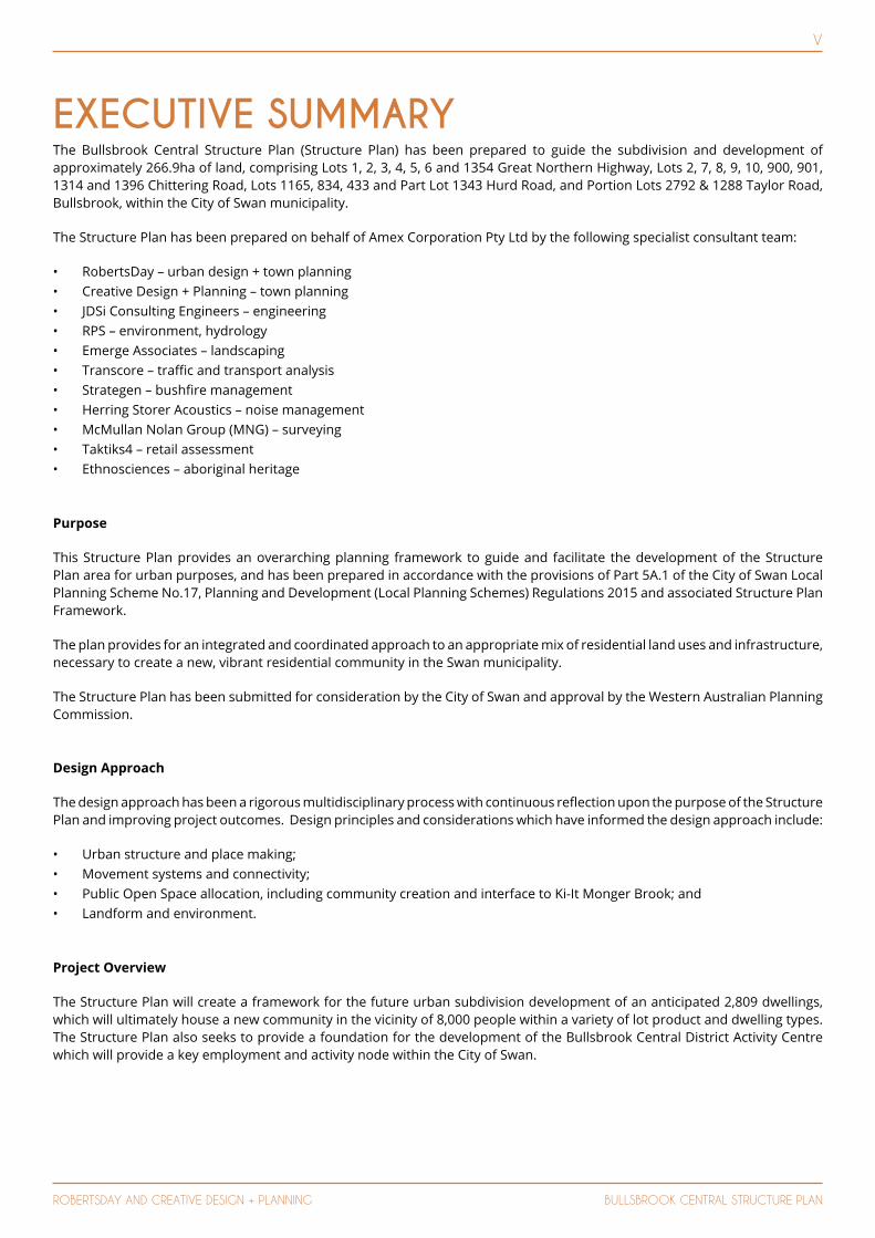
EXECUTIVE SUMMARYThe Bullsbrook Central Structure Plan (Structure Plan) has been prepared to guide the subdivision and development of approximately 266.9ha of land, comprising Lots 1, 2, 3, 4, 5, 6 and 1354 Great Northern Highway, Lots 2, 7, 8, 9, 10, 900, 901, 1314 and 1396 Chittering Road, Lots 1165, 834, 433 and Part Lot 1343 Hurd Road, and Portion Lots 2792 & 1288 Taylor Road, Bullsbrook, within the City of Swan municipality.
The Structure Plan has been prepared on behalf of Amex Corporation Pty Ltd by the following specialist consultant team:
• RobertsDay – urban design + town planning • Creative Design + Planning – town planning• JDSi Consulting Engineers – engineering • RPS – environment, hydrology • Emerge Associates – landscaping • Transcore – traffic and transport analysis• Strategen – bushfire management• Herring Storer Acoustics – noise management• McMullan Nolan Group (MNG) – surveying• Taktiks4 – retail assessment • Ethnosciences – aboriginal heritage
Purpose
This Structure Plan provides an overarching planning framework to guide and facilitate the development of the Structure Plan area for urban purposes, and has been prepared in accordance with the provisions of Part 5A.1 of the City of Swan Local Planning Scheme No.17, Planning and Development (Local Planning Schemes) Regulations 2015 and associated Structure Plan Framework.
The plan provides for an integrated and coordinated approach to an appropriate mix of residential land uses and infrastructure, necessary to create a new, vibrant residential community in the Swan municipality.
The Structure Plan has been submitted for consideration by the City of Swan and approval by the Western Australian Planning Commission.
Design Approach
The design approach has been a rigorous multidisciplinary process with continuous reflection upon the purpose of the Structure Plan and improving project outcomes. Design principles and considerations which have informed the design approach include:
• Urban structure and place making;• Movement systems and connectivity;• Public Open Space allocation, including community creation and interface to Ki-It Monger Brook; and• Landform and environment.
Project Overview
The Structure Plan will create a framework for the future urban subdivision development of an anticipated 2,809 dwellings, which will ultimately house a new community in the vicinity of 8,000 people within a variety of lot product and dwelling types. The Structure Plan also seeks to provide a foundation for the development of the Bullsbrook Central District Activity Centre which will provide a key employment and activity node within the City of Swan.

vi
ROBERTSDAY AND CREATIVE DESIGN + PLANNING BULLSBROOK CENTRAL STRUCTURE PLAN
EXECUTIVE SUMMARY TABLE
ITEM DATA STRUCTURE PLAN REFERENCE
Total area covered by the Structure Plan 267.02ha
Area of each land use proposed (approx.):
Residential:
General Commercial:
Private Clubs & Institutions:
Recreation (including drainage):
Public Purpose (Primary School):
Roads (inclusive of ‘Primary Regional Roads’ Reservation):
138.7ha
11.65ha
0.21ha
45.18ha
3.5 ha
67.78ha
Total estimated lot yield 2,809 lots
Estimated number of dwellings 2,809 dwellings
Estimated residential site density ~ 15+ dwellings/gross urban zone 1
~ 20.25 dwellings/site hectare 2
Estimated population
(based on 2.8 persons per dwelling)
7,865 people
Number of high schools 0
Number of primary schools 1
Estimated commercial floor space 25,000m2 nla
Estimated number and % of public open space given over to:
Regional Open Space:
District Open Space:
Neighbourhood Parks (>3,000m2):
Local Parks (<3,000m2):
0ha
6.3ha (2.4%)
18 parks @ 25.31ha (9.5% of total Structure Plan area)
1 park @ 0.27ha (~0.1% of total Structure Plan area)
FOOTNOTES:
1 Gross Urban Zone’ refers to the definition under WAPC’s Directions 2031 and supporting documents.
2 ‘Residential Site Hectare’ refers to the definition under Element 1 of WAPC’s Liveable Neighbourhoods.

vii
ROBERTSDAY AND CREATIVE DESIGN + PLANNING BULLSBROOK CENTRAL STRUCTURE PLAN
CONTENTSPART ONE - iMPLEMENTATiON
1 STRUCTURE PLAN AREA ..................................................................................................32 OPERATION .....................................................................................................................33 STAGING ..........................................................................................................................34 SUBDIVISION AND DEVELOPMENT REQUIREMENTS .................................................3
4.1 Structure Plan Map ................................................................................................................................... 34.2 Land Use Permissibility ............................................................................................................................ 34.3 Hazards and Separation Areas ............................................................................................................... 34.4 Major Infrastructure ................................................................................................................................. 34.5 Public Open Space .................................................................................................................................... 34.6 Residential Density Targets ..................................................................................................................... 34.7 Density Plans ............................................................................................................................................. 5
5 LOCAL DEVELOPMENTS PLANS .....................................................................................55.1 Prescribed Requirements ........................................................................................................................ 55.2 City of Swan Local Planning Policy POL-LP-11 Variation to Deemed to Comply Requirements of the R-Codes – Medium Density Single House Development Standards. ...................................... 6
6 OTHER REQUIREMENTS .................................................................................................66.1 Notifications on Title ................................................................................................................................ 66.2 Development Contributions .................................................................................................................... 6
7 ADDITIONAL INFORMATION .........................................................................................6
PART TWO - EXPLANATORY SECTiON AND TECHNiCAL STUDiES
1 PLANNING BACKGROUND ...........................................................................................111.1 Purpose .................................................................................................................................................... 111.2 Land Description ..................................................................................................................................... 11
1.2.1 Location ........................................................................................................................................... 111.2.2 Area, Land Use and Ownership .................................................................................................... 11
1.3 Planning Framework .............................................................................................................................. 111.3.1 Zoning & Reservations ................................................................................................................... 11
1.3.1.1 Metropolitan Region Scheme ........................................................................................... 111.3.1.2 City of Swan Local Planning Scheme No.17 .................................................................... 11
1.3.2 Regional & Sub Regional Structure Plans and Strategies .......................................................... 111.3.2.1 Directions 2031 and Beyond ............................................................................................. 111.3.2.2 Draft Outer Metropolitan Perth & Peel Sub-Regional Strategy .................................... 161.3.2.3 Draft Perth and Peel @3.5 Million .................................................................................... 161.3.2.4 Draft Perth and peel Green Growth Plan for 3.5 Million ............................................... 16
1.3.3 Significant Planning Strategies .................................................................................................... 161.3.3.1 City of Swan Urban Housing Strategy ............................................................................. 161.3.3.2 City of Swan Bullsbrook Townsite Landuse Masterplan ............................................... 16
1.3.4 Relevant Local Government Planning Policies & Strategies ...................................................... 161.3.5 Relevant State Planning Policies ................................................................................................... 17
1.3.5.1 State Planning Policy 2.4 – Basic Raw Materials ............................................................ 172 SITE CONDITIONS AND CONSTRAINTS .......................................................................20
2.1 Biodiversity and Natural Area Assets ................................................................................................... 202.1.1 Vegetation ...................................................................................................................................... 20
2.1.1.1 Regional Vegetation ........................................................................................................... 202.1.1.2 Threatened Ecological Communities ............................................................................... 202.1.1.3 Remnant Vegetation ......................................................................................................... 20
2.1.2 Flora ................................................................................................................................................. 202.1.3 Bush Forever .................................................................................................................................. 212.1.4 Fauna .............................................................................................................................................. 21
2.2 Landform and Soils ................................................................................................................................ 212.2.1 Topography .................................................................................................................................... 21

viii
ROBERTSDAY AND CREATIVE DESIGN + PLANNING BULLSBROOK CENTRAL STRUCTURE PLAN
2.2.2 Regional Geomorphology.............................................................................................................. 212.2.3 Acid Sulphate Soils ........................................................................................................................ 21
2.3 Groundwater and Surface Water .......................................................................................................... 232.3.1 Groundwater .................................................................................................................................. 23
2.3.1.1 Regional Groundwater Levels .......................................................................................... 232.3.1.2 Site Groundwater Levels .................................................................................................. 232.3.1.3 Groundwater Quality ....................................................................................................... 23
2.3.2 Surface Water ................................................................................................................................ 232.3.3 Wetlands and Waterways .............................................................................................................. 232.3.4 Monitoring ...................................................................................................................................... 24
2.4 Heritage ................................................................................................................................................... 242.5 Bushfire .................................................................................................................................................... 242.6 Context and Other Land Use Constraints and Opportunities........................................................... 24
2.6.1 Noise ............................................................................................................................................... 242.6.1.1 Nursery .............................................................................................................................. 242.6.1.2 Great Northern Highway & Chittering Road .................................................................. 24
2.6.2 Potential Contamination .............................................................................................................. 242.6.3 Landfill Site ..................................................................................................................................... 24
2.7 Existing Movement Networks .............................................................................................................. 252.7.1 Great Northern Highway ............................................................................................................... 252.7.2 Chittering Road ............................................................................................................................... 252.7.3 Existing Pedestrian and Cyclist Networks ................................................................................... 252.7.4 Existing Public Transport ............................................................................................................... 25
3 LAND USE AND SUBDIVISION REQUIREMENTS .........................................................273.1 Land Use ...................................................................................................................................................... 27
3.1.1 Education ......................................................................................................................................... 273.1.2 District and Regional Open Space ............................................................................................... 273.1.3 Activity Centres and Employment ................................................................................................ 273.1.4 Community Facilities ...................................................................................................................... 27
3.2 External Design Influences .................................................................................................................... 273.2.1 Acoustics & Noise Targets ............................................................................................................ 27
3.2.1.1 Pearce RAAF Base .............................................................................................................. 273.2.1.2 Great Northern Highway .................................................................................................. 273.2.1.3 Chittering Road .................................................................................................................. 27
3.2.2 Bush Fire Management ................................................................................................................. 273.3 Design Philosophy .................................................................................................................................. 323.4 Opportunities and Constraints ............................................................................................................ 34
3.4.1 Landform ........................................................................................................................................ 353.4.2 Views and Landscape .................................................................................................................... 35
3.5 Place Vision ............................................................................................................................................ 363.6 Place Design Principles ........................................................................................................................ 37
3.6.1 Immersed in the Landscape ......................................................................................................... 373.6.2 Village of 3 Neighbourhoods ........................................................................................................ 37
3.6.2.1 Brook ................................................................................................................................... 373.6.2.2 Heart ................................................................................................................................... 373.6.2.3 Hill-top ................................................................................................................................ 37
3.6.3 Connected by Nature ..................................................................................................................... 383.6.4 Transit Village .................................................................................................................................. 383.6.5 Integrated Village Centre Heart ................................................................................................... 393.6.6 Connected Open Space Network ................................................................................................ 39
3.7 Variations from the BTLUMP ................................................................................................................ 403.7.1 District Open Space ....................................................................................................................... 403.7.2 Rapid Transit Activity Corridor and Chittering Road .................................................................. 403.7.3 Primary School ............................................................................................................................... 42
3.8 Land Composition .................................................................................................................................. 423.9 Primary School Site ................................................................................................................................. 423.10 Dwelling Forecasts ............................................................................................................................... 43
3.10.1 Projected Dwellings ........................................................................................................................ 433.10.2 Directions 2031 Forecasts ............................................................................................................. 433.10.3 Liveable Neighbourhoods Forecasts ........................................................................................... 43
3.11 Residential Density Coding ................................................................................................................. 443.11.1 Residential R5 - R20 Precinct ......................................................................................................... 44
iX
ROBERTSDAY AND CREATIVE DESIGN + PLANNING BULLSBROOK CENTRAL STRUCTURE PLAN
3.11.2 Residential R10 – R30 Precinct ..................................................................................................... 443.11.3 Residential R20 – R50 Precinct ...................................................................................................... 453.11.4 Residential R50 - 60 Precinct ......................................................................................................... 45
3.12 Local Development Plans .................................................................................................................... 463.12.1 Prescribed Requirements .............................................................................................................. 463.12.2 Other Built Form and Streetscape Provisions ............................................................................ 46
3.13 District Activity Centre ......................................................................................................................... 463.13.1 Overview ......................................................................................................................................... 463.13.2 Vision................................................................................................................................................ 463.13.3 Built Form ........................................................................................................................................ 47
3.13.3.1 Guiding Principles ............................................................................................................ 473.13.3.2 Urban Elements ............................................................................................................... 473.13.3.3 Design Principles ............................................................................................................. 473.13.3.4 Landscape Principles ....................................................................................................... 473.13.3.5 Design Intent ................................................................................................................... 473.13.3.6 Objectives ........................................................................................................................ 473.13.3.7 Materials & Colour ........................................................................................................... 473.13.3.8 Design Intent .................................................................................................................... 473.13.3.9 Objectives ......................................................................................................................... 48
3.14 Movement Networks ........................................................................................................................... 483.14.1 Primary External Road Network .................................................................................................. 483.14.2 Site Access ...................................................................................................................................... 483.14.3 Proposed Internal Road Network Configuration and Hierarchy ............................................. 48
3.14.3.1 Integrator B ...................................................................................................................... 493.14.3.2 Neighbourhood Connectors ......................................................................................... 503.14.3.3 Neighbourhood Connector A ......................................................................................... 503.14.3.4 Neighbhourhood Connector B....................................................................................... 503.14.3.5 Access Streets ................................................................................................................. 51
3.14.4 Public Transport ............................................................................................................................. 513.14.5 Pedestrian and Cycle Infrastructure ............................................................................................ 513.14.6 Integration with the Surrounding Area ....................................................................................... 51
3.15 Public Open Space ............................................................................................................................... 513.15.1 Local Amenity .................................................................................................................................. 513.15.2 Linear Open Space Network ........................................................................................................ 543.15.3 Living Streams ................................................................................................................................. 543.15.4 Ki-it Monger Brook ........................................................................................................................ 543.15.5 District Open Space (Playing Fields) ............................................................................................. 54
3.16 Street Trees and Retention ................................................................................................................. 553.17 Urban Water Management ................................................................................................................. 553.18 Education Facilities ............................................................................................................................... 613.19 Infrastructure Coordination, Servicing and Staging ......................................................................... 61
3.19.1 Ground Conditions ......................................................................................................................... 613.19.2 Sewage ............................................................................................................................................ 613.19.3 Water Supply .................................................................................................................................. 623.19.4 Power Supply ................................................................................................................................. 623.19.5 Telecommunications ..................................................................................................................... 623.19.6 Gas .................................................................................................................................................. 623.19.7 Roads .............................................................................................................................................. 623.19.8 Stormwater Management & Drainage ....................................................................................... 62
3.20 Development Contributions Arrangements ...................................................................................... 623.21 Other Requirements .............................................................................................................................. 62
3.21.1 Staging ............................................................................................................................................. 624 TECHNICAL STUDIES (APPENDICES) INDEX ................................................................63
X
ROBERTSDAY AND CREATIVE DESIGN + PLANNING BULLSBROOK CENTRAL STRUCTURE PLAN
PLANSPlan 1 – Structure Plan
FIGURESFigure 1 – Location PlanFigure 2 – Metropolitan Region SchemeFigure 3 – Local Planning Scheme No.17Figure 4 – Structure Plan Local Planning Scheme Zoning OverlayFigure 5 – draft North East Sub-regional Planning FrameworkFigure 6 – Bullsbrook Townsite Land Use MasterplanFigure 7 – TopographyFigure 8 – OrthophotoFigure 9 – District Context PlanFigure 10 – Concept MasterplanFigure 11 – Opportunities and ConstraintsFigure 12 – LandformFigure 13 – Views and Landscape Figure 14.1 – Imersed in the LandscapeFigure 14.2 – Village of 3 NeighbourhoodsFigure 14.3 – Connected by Nature Figure 14.4 – Transit VillageFigure 14.5 – Connected Open Space NetworkFigure 14.6 – Integrated Village CentreFigure 15 – Modified Bullsbrook Townsite Land use MasterplanFigure 16 – Walkable CatchmentsFigure 17 – Road Hierarchy Figure 18 – Integrator B Cross Section 20.0mFigure 19 – Integrator B Cross Section 25.0/27.0mFigure 20 – Neighbourhood Connector A Cross Section 20.0mFigure 21 – Public Open SpaceFigure 22 – Ki-It Monger Brook Cross SectionFigure 23 – Landscape MasterplanFigure 24 – Green Streets Figure 25 – Neighbourhood Parks Figure 26 – Playing FieldsFigure 27 – Ki-it Monger Brook
TECHNICAL STUDIES (APPENDICES)Appendix 1: Bushfire Management Plan (StrategenAppendix 2: Transportation Noise Assessment (Herring Storer)Appendix 3: Certificated of Title & Clause 42Appendix 4: Environmental Summary Report (RPS Environment)Appendix 5: Local Water Management Strategy (RPS Hydrology)Appendix 6: Aboriginal Heritage Desktop Assessment (Ethnosciences)Appendix 7: Transport Assessment (Transcore)Appendix 8: District Activity Centre ‘Precedent Imagery’ (Taylor Robinson)Appendix 9: Retail Market Demand Review (Taktiks4)Appendix 10: Landscape and Irrigation Strategy (Emerge)Appendix 11: Engineering Servicing Report (JDSi)

Xi
ROBERTSDAY AND CREATIVE DESIGN + PLANNING BULLSBROOK CENTRAL STRUCTURE PLAN
ABBREVIATIONSAHD Australian Height Datum
ANZECC Australian and New Zealand Environment Conservation Council
ASS Acid Sulfate Soils
AS Australian Standard
BGL Below Ground Level
BMP Bushfire Management Plan
BRA Bio-Retention Areas
BRT Ellenbrook Bus Rapid Transit
CBD Central Business District
CCW Conservation Category Wetland
CoS City of Swan
DAA Department of Aboriginal Affairs
DER Department of Environment Regulation
DPaW Department of Parks and Wildlife
DoP Department of Planning
DoW Department of Water
EPA Environmental Protection Authority
FSA Flood Storage Areas
Ha Hectare
LDP Local Development Plan
LILO Left-in /Left-Out Road Intersection
LWMS Local Water Management Strategy
MGL Maximum Groundwater Level
MRS Metropolitan Region Scheme
MRWA Main Roads Western Australia
NESRF Draft North-East Sub-Regional Planning Framework
OMSRS Draft Outer Metropolitan Perth & Peel Sub Regional Structure Plan
POS Public Open Space
PTA Public Transport Authority
UWMP Urban Water Management Plan
vpd Vehicles per day
WAPC Western Australian Planning Commission
WSUD Water Sensitive Urban Design
2
CREATIVE DESIGN + PLANNING BULLSBROOK CENTRAL STRUCTURE PLAN
PART ONEImplementationBULLSBROOK CENTRAL STRUCTURE PLAN
1. Structure Plan Area
2. Operation
3. Staging
4. Subdivision and Development Requirements
5. Local Development Plans
6. Other Requirements
7. Additional Information
8. Bullsbrook Central Structure Plan (Plan 1)
3
ROBERTSDAY AND CREATIVE DESIGN + PLANNING BULLSBROOK CENTRAL STRUCTURE PLAN
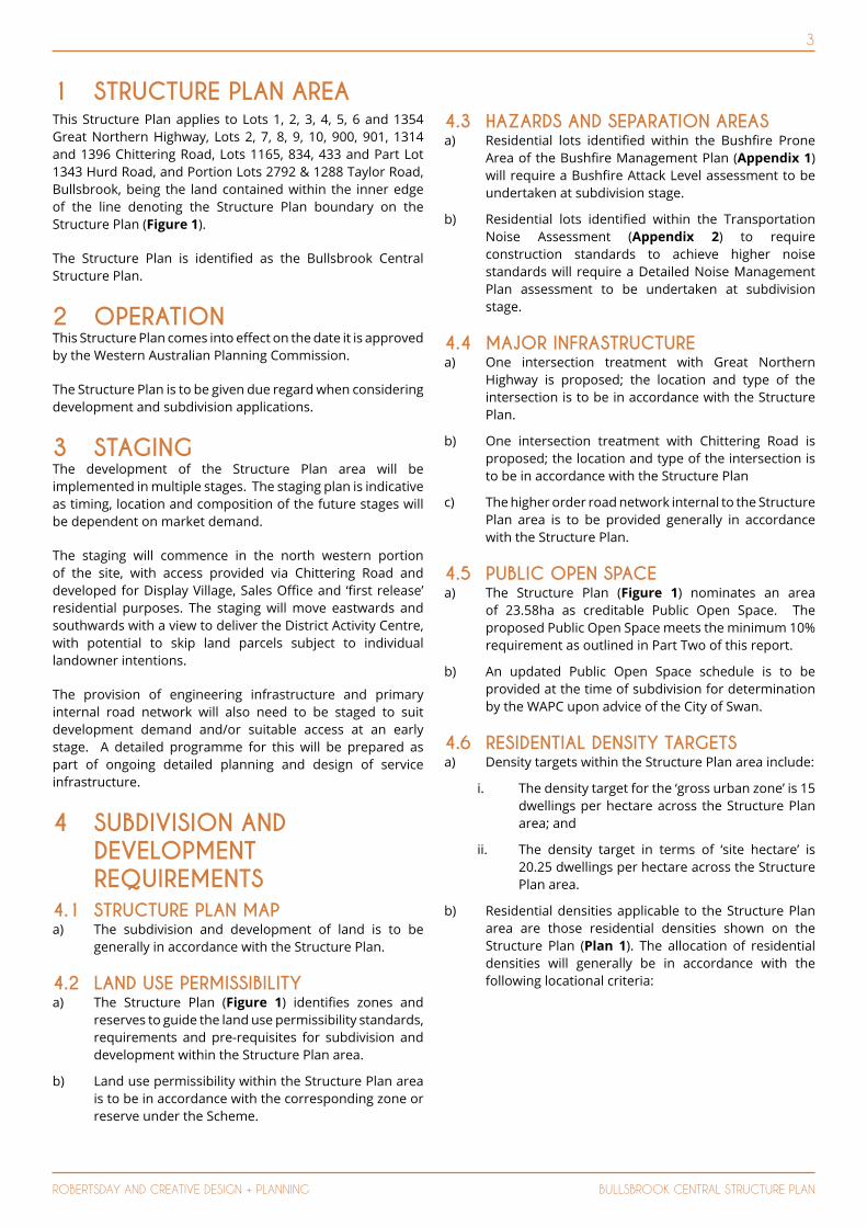
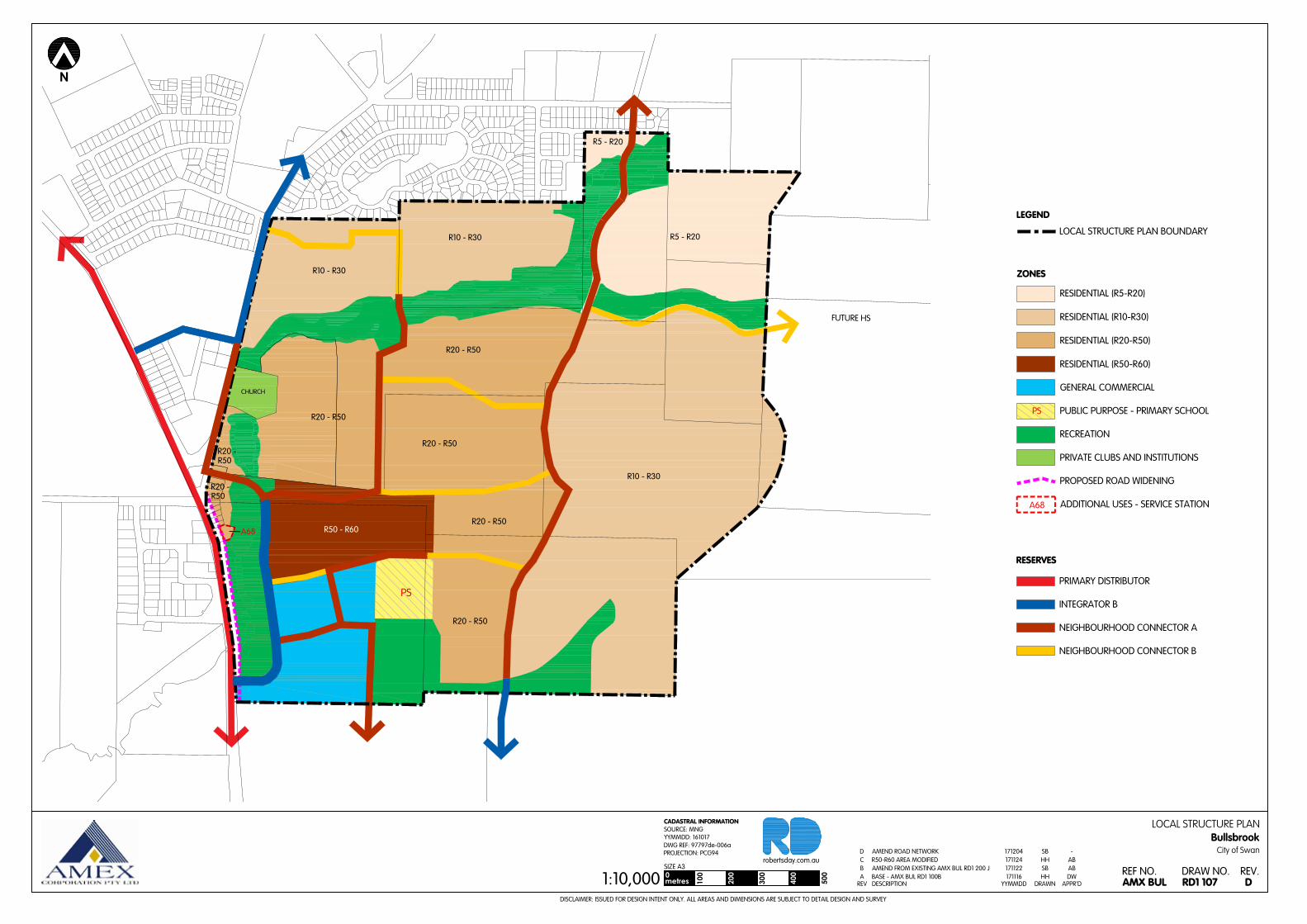
This Structure Plan applies to Lots 1, 2, 3, 4, 5, 6 and 1354 Great Northern Highway, Lots 2, 7, 8, 9, 10, 900, 901, 1314 and 1396 Chittering Road, Lots 1165, 834, 433 and Part Lot 1343 Hurd Road, and Portion Lots 2792 & 1288 Taylor Road, Bullsbrook, being the land contained within the inner edge of the line denoting the Structure Plan boundary on the Structure Plan (Figure 1).
The Structure Plan is identified as the Bullsbrook Central Structure Plan.
2 OPERATION This Structure Plan comes into effect on the date it is approved by the Western Australian Planning Commission.
The Structure Plan is to be given due regard when considering development and subdivision applications.
3 STAGING The development of the Structure Plan area will be implemented in multiple stages. The staging plan is indicative as timing, location and composition of the future stages will be dependent on market demand.
The staging will commence in the north western portion of the site, with access provided via Chittering Road and developed for Display Village, Sales Office and ‘first release’ residential purposes. The staging will move eastwards and southwards with a view to deliver the District Activity Centre, with potential to skip land parcels subject to individual landowner intentions.
The provision of engineering infrastructure and primary internal road network will also need to be staged to suit development demand and/or suitable access at an early stage. A detailed programme for this will be prepared as part of ongoing detailed planning and design of service infrastructure.
4 SUBDIVISION AND DEVELOPMENT REQUIREMENTS
4.1 STRUCTURE PLAN MAPa) The subdivision and development of land is to be
generally in accordance with the Structure Plan.
4.2 LAND USE PERMISSIBILITYa) The Structure Plan (Figure 1) identifies zones and
reserves to guide the land use permissibility standards, requirements and pre-requisites for subdivision and development within the Structure Plan area.
b) Land use permissibility within the Structure Plan area is to be in accordance with the corresponding zone or reserve under the Scheme.
4.3 HAZARDS AND SEPARATION AREASa) Residential lots identified within the Bushfire Prone
Area of the Bushfire Management Plan (Appendix 1) will require a Bushfire Attack Level assessment to be undertaken at subdivision stage.
b) Residential lots identified within the Transportation Noise Assessment (Appendix 2) to require construction standards to achieve higher noise standards will require a Detailed Noise Management Plan assessment to be undertaken at subdivision stage.
4.4 MAJOR INFRASTRUCTUREa) One intersection treatment with Great Northern
Highway is proposed; the location and type of the intersection is to be in accordance with the Structure Plan.
b) One intersection treatment with Chittering Road is proposed; the location and type of the intersection is to be in accordance with the Structure Plan
c) The higher order road network internal to the Structure Plan area is to be provided generally in accordance with the Structure Plan.
4.5 PUBLIC OPEN SPACEa) The Structure Plan (Figure 1) nominates an area
of 23.58ha as creditable Public Open Space. The proposed Public Open Space meets the minimum 10% requirement as outlined in Part Two of this report.
b) An updated Public Open Space schedule is to be provided at the time of subdivision for determination by the WAPC upon advice of the City of Swan.
4.6 RESIDENTIAL DENSITY TARGETSa) Density targets within the Structure Plan area include:
i. The density target for the ‘gross urban zone’ is 15 dwellings per hectare across the Structure Plan area; and
ii. The density target in terms of ‘site hectare’ is 20.25 dwellings per hectare across the Structure Plan area.
b) Residential densities applicable to the Structure Plan area are those residential densities shown on the Structure Plan (Plan 1). The allocation of residential densities will generally be in accordance with the following locational criteria:
1 STRUCTURE PLAN AREA

4
ROBERTSDAY AND CREATIVE DESIGN + PLANNING BULLSBROOK CENTRAL STRUCTURE PLAN
DENSITY CODING
GENERAL LOCATION PRINCIPLES CRITERIA
R5-R20 Precinct R5 Applies to majority of Precinct
supporting delivery of front loaded product.
Applies as the base code.
R10-20 Located in general proximity to public open space, key distributor roads and bus routes.
Notwithstanding achieving the respective minimum and average site area per dwelling, criteria applies to:
a) lots generally within, but not exclusive to, 100m walking distance of public open space and key distributor roads; or
b) lots generally within, but not exclusive to, 400m walking distance of key public transport nodes and routes.
R10-R30 Precinct R10 Applies to majority of Precinct
supporting delivery of traditional front loaded product.
Applies as the base code.
R20-30 Located in general proximity to public open space, key distributor roads, bus routes and schools
Notwithstanding achieving the respective minimum and average site area per dwelling, criteria applies to:
c) lots generally within, but not exclusive to, 100m walking distance of public open space and key distributor roads;
d) lots generally within, but not exclusive to, 400m walking distance of key public transport nodes and routes and schools; or
e) lots with:
i. direct frontage to two intersecting roads and with a site area of 1,000m2 or greater; and/or
ii. designated Grouped Dwelling sites.
R20-R50 Precinct R20 Applies to majority of the Precinct
supporting delivery of traditional front loaded product.
Applies as the base code.
R30-50 Located in general proximity to public open space, key distributor roads, bus routes, schools and commercial nodes.
Notwithstanding achieving the respective minimum and average site area per dwelling, criteria applies to:
f) lots generally within, but not exclusive to, 100m walking distance of public open space and key distributor roads;
g) lots generally within, but not exclusive to, 400m walking distance of key public transport nodes and routes, schools and commercial nodes; or
h) lots with:
i. direct frontage to two intersecting roads and with a site area of 1,000m2 or greater; and/or
ii. designated Grouped or Multiple Dwelling sites.
R50-R60 PrecinctR50 Applies to majority of the Precinct
supporting delivery of traditional front and rear loaded product.
Applies as the base code.

5
ROBERTSDAY AND CREATIVE DESIGN + PLANNING BULLSBROOK CENTRAL STRUCTURE PLAN
R60 Located in general proximity to public open space, key distributor roads, bus routes and commercial nodes.
Notwithstanding achieving the respective minimum and average site area per dwelling, criteria applies to:
i) lots with a laneway abutting the rear boundary;
j) lots generally within, but not exclusive to, 100m walking distance of public open space, key public transport nodes and routes and commercial nodes; or
k) lots with:
i. direct frontage to two intersecting roads and with a site area of 1,000m2 or greater; and/or
ii. designated Grouped or Multiple Dwelling sites.
4.7 DENSITY PLANSThe Structure Plan defines the residential ranges that apply to specific areas within the Structure Plan.
Lot specific residential densities, within the defined residential density ranges, are to be subsequently assigned in accordance with a Residential Density Code Plan approved by the WAPC at subdivision stage.
A Residential Density Code Plan is to be submitted at the time of subdivision to the WAPC and will indicate the Residential Density Coding applicable to each lot within the subdivision consistent with the Structure Plan, the Residential Density Ranges identified on the Structure Plan and location criteria contained in Clause 4.6.
The Density Plan is to include a summary of the proposed dwelling yield of the subdivision and demonstrate how the density target within the Structure Plan, as specified in Clause 4.6, is progressively being achieved.
Approval of the Density Plan is to be undertaken at the time of determination of the subdivision application by the WAPC. The approved Density Plan is to then form part of the Structure Plan and shall be used for the determination of future development applications.
Density Plans are not required if the WAPC considers that the subdivision is for one or more of the following:
a) The amalgamation of lots;
b) The purposes of facilitating the provision of access, services or infrastructure;
c) Land which by virtue of its zoning or reservation under the Structure Plan cannot be developed for residential purposes; or
d) Land which by virtue of its zoning under the Structure Plan is not subject to a density range.
5 LOCAL DEVELOPMENTS PLANS
Local Development Plans will be prepared for the Structure Plan area pursuant to the WAPC’s Local Development Plan Framework and Schedule 2, ‘Deemed Provisions for Local Planning Schemes’ of the Planning and Development (Local Planning Schemes) Regulations 2015.
5.1 PRESCRIBED REQUIREMENTSLocal Development Plans are to be prepared and implemented for lots comprising one or more of the following site attributes:
a) Lots affected by noise which exceeds the noise target as defined by the State Planning Policy 5.4 in relation to Great Northern Highway and Chittering Road;
b) Lots within a 100m catchment of ‘Classified Vegetation’ (Bushfire Hazard Zone) thus deemed at risk from bushfire pursuant to Australian Standards;
c) Lots with an interface or outlook toward Public Open Space;
d) Lots that propose grouped or multiple dwelling development; and
e) Lots that obtain access from a laneway or right-of-way.
6
ROBERTSDAY AND CREATIVE DESIGN + PLANNING BULLSBROOK CENTRAL STRUCTURE PLAN
5.2 CITY OF SWAN LOCAL PLANNING POLICY POL-LP-11 VARIATION TO DEEMED TO COMPLY REQUIREMENTS OF THE R-CODES – MEDIUM DENSITY SINGLE HOUSE DEVELOPMENT STANDARDS.
A Local Development Plan is not required to vary ‘Deemed to Comply’ provisions of the Residential Design Codes where such variations are adopted under City of Swan Local Planning Policy (POL-LP-11) – Variation to Deemed to Comply Requirements of the R-Codes – Medium Density Single House Development Standards.
Such variations may include design provisions relating to:
• Street Setback and Front Fences;• Boundary Setbacks;• Boundary Walls;• Open Space;• Garage Setbacks and width and vehicular access;• Overshadowing; and• Privacy.
6 OTHER REQUIREMENTS 6.1 NOTIFICATIONS ON TITLEIn respect of applications for the subdivision of land the City of Swan may recommend to the Western Australian Planning Commission that a condition be imposed on the granting of subdivision approval for a notification to be placed on the Certificate(s) of Title(s) to advise of the following:
a) Construction standards to achieve higher noise standards in accordance with State Planning Policy 5.4 ‘Road and Rail; Transportation Noise and Freight Considerations in Land Use Planning’.
b) Building setbacks and construction standards to achieve a Bushfire Attack Level -29 or lower in accordance with ‘Australian Standards (AS3959-2009): Construction of buildings in bushfire prone areas’.
6.2 DEVELOPMENT CONTRIBUTIONSThe Structure Plan area will be subject to a Development Contribution Plan (DCP) pursuant to Local Planning Scheme No. 17 and guided by State Planning Policy 3.6 – Development Contributions for Infrastructure. The DCP will be generally guided by the following documents:
• Local Structure Plans and associated appendices; • City of Swan Transport Strategy; and• Bullsbrook Townsite Land Use Masterplan
7 ADDITIONAL INFORMATION Additional Information Approval Stage Consultation Required
Density Plans Subdivision application WAPC
City of Swan
Public Open Space Schedule Subdivision application City of Swan
Detailed Noise Management Plan
• Subdivision application/condition of subdivision for identified lots, or
• Development application for identified lots.
City of Swan
Bushfire Attack Level Assessment
• Subdivision application/condition of subdivision for identified lots, or
• Development application for identified lots
City of Swan
Department of Fire and Emergency Services
Ki-It Monger Brook Foreshore Management Plan
Condition of subdivision for relevant landowner/stage adjacent Foreshore
City of Swan
Wetland Management Plan Condition of subdivision for relevant landowner/stage adjacent Wetland
City of Swan
R20 - R50
R50 - R60
R20 - R50
R20 - R50
FUTURE HS
R10 - R30
R10 - R30 R5 - R20
R5 - R20
R20 -R50
A68
R10 - R30
R20 - R50
R20 -R50
CHURCH
PS
R20 - R50
N
DISCLAIMER: ISSUED FOR DESIGN INTENT ONLY. ALL AREAS AND DIMENSIONS ARE SUBJECT TO DETAIL DESIGN AND SURVEY
LOCAL STRUCTURE PLANBullsbrook
City of Swan
SIZE A3robertsday.com.au
CADASTRAL INFORMATIONSOURCE: MNGYYMMDD: 161017DWG REF: 97797de-006aPROJECTION: PCG94
RD1 107DRAW NO.
DAMX BULREF NO. REV.1:10,000 10
00metres 20
0
300
400
500
LOCAL STRUCTURE PLAN BOUNDARY
LEGEND
ZONES
RESIDENTIAL (R5-R20)
RESIDENTIAL (R10-R30)
RESIDENTIAL (R20-R50)
RESIDENTIAL (R50-R60)
GENERAL COMMERCIAL
PUBLIC PURPOSE - PRIMARY SCHOOL
RECREATION
PRIVATE CLUBS AND INSTITUTIONS
PROPOSED ROAD WIDENING
ADDITIONAL USES - SERVICE STATION
RESERVES
PRIMARY DISTRIBUTOR
INTEGRATOR B
NEIGHBOURHOOD CONNECTOR A
NEIGHBOURHOOD CONNECTOR B
PS
A68
SBHHSBHH
-ABABDW
171204171124171122171116
DRAWNREV APPR'DYYMMDDDESCRIPTION
AMEND ROAD NETWORKR50-R60 AREA MODIFIEDAMEND FROM EXISTING AMX BUL RD1 200 JBASE - AMX BUL RD1 100B
DCBA
R20 - R50
R50 - R60
R20 - R50
R20 - R50
FUTURE HS
R10 - R30
R10 - R30 R5 - R20
R5 - R20
R20 -R50
A68
R10 - R30
R20 - R50
R20 -R50
CHURCH
PS
R20 - R50
N
DISCLAIMER: ISSUED FOR DESIGN INTENT ONLY. ALL AREAS AND DIMENSIONS ARE SUBJECT TO DETAIL DESIGN AND SURVEY
LOCAL STRUCTURE PLANBullsbrook
City of Swan
SIZE A3robertsday.com.au
CADASTRAL INFORMATIONSOURCE: MNGYYMMDD: 161017DWG REF: 97797de-006aPROJECTION: PCG94
RD1 107DRAW NO.
DAMX BULREF NO. REV.1:10,000 10
00metres 20
0
300
400
500
LOCAL STRUCTURE PLAN BOUNDARY
LEGEND
ZONES
RESIDENTIAL (R5-R20)
RESIDENTIAL (R10-R30)
RESIDENTIAL (R20-R50)
RESIDENTIAL (R50-R60)
GENERAL COMMERCIAL
PUBLIC PURPOSE - PRIMARY SCHOOL
RECREATION
PRIVATE CLUBS AND INSTITUTIONS
PROPOSED ROAD WIDENING
ADDITIONAL USES - SERVICE STATION
RESERVES
PRIMARY DISTRIBUTOR
INTEGRATOR B
NEIGHBOURHOOD CONNECTOR A
NEIGHBOURHOOD CONNECTOR B
PS
A68
SBHHSBHH
-ABABDW
171204171124171122171116
DRAWNREV APPR'DYYMMDDDESCRIPTION
AMEND ROAD NETWORKR50-R60 AREA MODIFIEDAMEND FROM EXISTING AMX BUL RD1 200 JBASE - AMX BUL RD1 100B
DCBA


9
ROBERTSDAY AND CREATIVE DESIGN + PLANNING BULLSBROOK CENTRAL STRUCTURE PLAN
THIS PAGE HAS BEEN INTENTIONALLY LEFT BLANK
10
CREATIVE DESIGN + PLANNING BULLSBROOK CENTRAL STRUCTURE PLAN
PART TWOExplanatory Section and Technical StudiesBULLSBROOK CENTRAL STRUCTURE PLAN
1. Planning Background
2. Site Conditions and Constraints
3. Land Use and Subdivision Requirements
4. Technical Studies (Appendices) Index
11
ROBERTSDAY AND CREATIVE DESIGN + PLANNING BULLSBROOK CENTRAL STRUCTURE PLAN
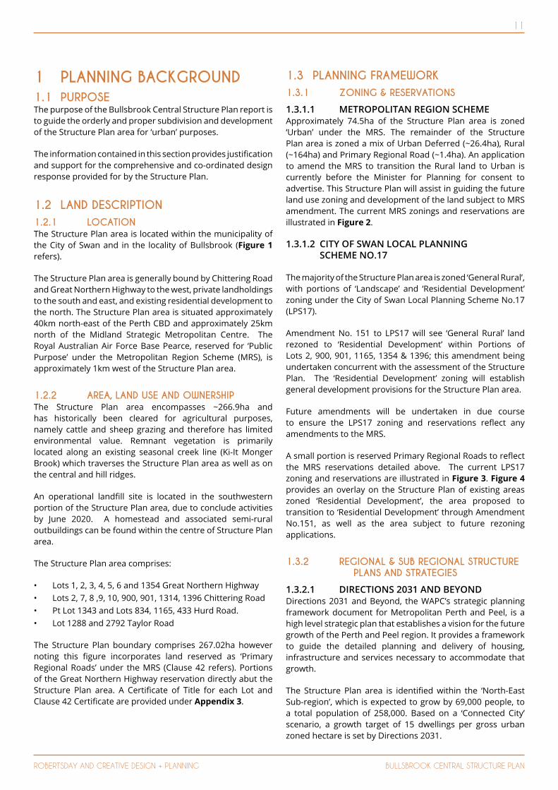
1 PLANNING BACKGROUND1.1 PURPOSEThe purpose of the Bullsbrook Central Structure Plan report is to guide the orderly and proper subdivision and development of the Structure Plan area for ‘urban’ purposes.
The information contained in this section provides justification and support for the comprehensive and co-ordinated design response provided for by the Structure Plan.
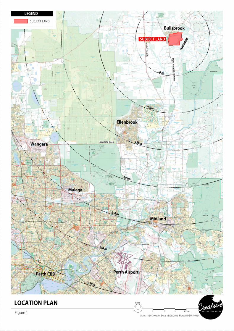
1.2 LAND DESCRIPTION1.2.1 LOCATIONThe Structure Plan area is located within the municipality of the City of Swan and in the locality of Bullsbrook (Figure 1 refers).
The Structure Plan area is generally bound by Chittering Road and Great Northern Highway to the west, private landholdings to the south and east, and existing residential development to the north. The Structure Plan area is situated approximately 40km north-east of the Perth CBD and approximately 25km north of the Midland Strategic Metropolitan Centre. The Royal Australian Air Force Base Pearce, reserved for ‘Public Purpose’ under the Metropolitan Region Scheme (MRS), is approximately 1km west of the Structure Plan area.
1.2.2 AREA, LAND USE AND OWNERSHIPThe Structure Plan area encompasses ~266.9ha and has historically been cleared for agricultural purposes, namely cattle and sheep grazing and therefore has limited environmental value. Remnant vegetation is primarily located along an existing seasonal creek line (Ki-It Monger Brook) which traverses the Structure Plan area as well as on the central and hill ridges.
An operational landfill site is located in the southwestern portion of the Structure Plan area, due to conclude activities by June 2020. A homestead and associated semi-rural outbuildings can be found within the centre of Structure Plan area.
The Structure Plan area comprises:
• Lots 1, 2, 3, 4, 5, 6 and 1354 Great Northern Highway• Lots 2, 7, 8 ,9, 10, 900, 901, 1314, 1396 Chittering Road• Pt Lot 1343 and Lots 834, 1165, 433 Hurd Road.• Lot 1288 and 2792 Taylor Road
The Structure Plan boundary comprises 267.02ha however noting this figure incorporates land reserved as ‘Primary Regional Roads’ under the MRS (Clause 42 refers). Portions of the Great Northern Highway reservation directly abut the Structure Plan area. A Certificate of Title for each Lot and Clause 42 Certificate are provided under Appendix 3.
1.3 PLANNING FRAMEWORK1.3.1 ZONING & RESERVATIONS
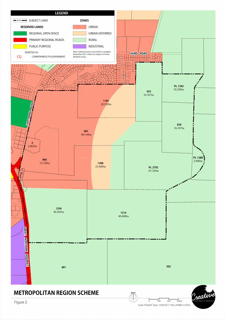
1.3.1.1 METROPOLITAN REGION SCHEME Approximately 74.5ha of the Structure Plan area is zoned ‘Urban’ under the MRS. The remainder of the Structure Plan area is zoned a mix of Urban Deferred (~26.4ha), Rural (~164ha) and Primary Regional Road (~1.4ha). An application to amend the MRS to transition the Rural land to Urban is currently before the Minister for Planning for consent to advertise. This Structure Plan will assist in guiding the future land use zoning and development of the land subject to MRS amendment. The current MRS zonings and reservations are illustrated in Figure 2.
1.3.1.2 CITY OF SWAN LOCAL PLANNING SCHEME NO.17
The majority of the Structure Plan area is zoned ‘General Rural’, with portions of ‘Landscape’ and ‘Residential Development’ zoning under the City of Swan Local Planning Scheme No.17 (LPS17).
Amendment No. 151 to LPS17 will see ‘General Rural’ land rezoned to ‘Residential Development’ within Portions of Lots 2, 900, 901, 1165, 1354 & 1396; this amendment being undertaken concurrent with the assessment of the Structure Plan. The ‘Residential Development’ zoning will establish general development provisions for the Structure Plan area.
Future amendments will be undertaken in due course to ensure the LPS17 zoning and reservations reflect any amendments to the MRS.
A small portion is reserved Primary Regional Roads to reflect the MRS reservations detailed above. The current LPS17 zoning and reservations are illustrated in Figure 3. Figure 4 provides an overlay on the Structure Plan of existing areas zoned ‘Residential Development’, the area proposed to transition to ‘Residential Development’ through Amendment No.151, as well as the area subject to future rezoning applications.
1.3.2 REGIONAL & SUB REGIONAL STRUCTURE PLANS AND STRATEGIES
1.3.2.1 DIRECTIONS 2031 AND BEYONDDirections 2031 and Beyond, the WAPC’s strategic planning framework document for Metropolitan Perth and Peel, is a high level strategic plan that establishes a vision for the future growth of the Perth and Peel region. It provides a framework to guide the detailed planning and delivery of housing, infrastructure and services necessary to accommodate that growth.
The Structure Plan area is identified within the ‘North-East Sub-region’, which is expected to grow by 69,000 people, to a total population of 258,000. Based on a ‘Connected City’ scenario, a growth target of 15 dwellings per gross urban zoned hectare is set by Directions 2031.
12
ROBERTSDAY AND CREATIVE DESIGN + PLANNING BULLSBROOK CENTRAL STRUCTURE PLAN
13
ROBERTSDAY AND CREATIVE DESIGN + PLANNING BULLSBROOK CENTRAL STRUCTURE PLAN

14
ROBERTSDAY AND CREATIVE DESIGN + PLANNING BULLSBROOK CENTRAL STRUCTURE PLAN
15
ROBERTSDAY AND CREATIVE DESIGN + PLANNING BULLSBROOK CENTRAL STRUCTURE PLAN
GREAT N
ORTH
ERN H
IGH
WAY
GREA
T NO
RTHERN
HIG
HW
AY
CHIT
TERI
NG
RO
AD
NOCURNE RISE
HURD ROAD
CAN
TATA
AVEN
UE
PARKLAND PARADE
CH
ITTE
RIN
G R
OAD
MR
S Road W
idening Plan 1.1409
CAPORN STREET
BREARLEY STREET
COMMUNITYCENTRE
PICKETT PARK
R20 - R50
R50 - R60
R20 - R50
R20 - R50
FUTURE HS
R10 - R30
R10 - R30 R5 - R20
R5 - R20
R20 -R50
A68
R10 - R30
R20 - R50
R20 -R50
CHURCH
PS
R20 - R50
N
DISCLAIMER: ISSUED FOR DESIGN INTENT ONLY. ALL AREAS AND DIMENSIONS ARE SUBJECT TO DETAIL DESIGN AND SURVEY
LOCAL STRUCTURE PLAN & LOCAL PLANNING SCHEMEBullsbrook
City of Swan
SIZE A3
AERIAL PHOTOGRAPHYSOURCE: NAYYMMDD: NA
robertsday.com.au
CADASTRAL INFORMATIONSOURCE: MNGYYMMDD: 161017DWG REF: 97797de-006aPROJECTION: PCG94
RD1 202DRAW NO.
BAMX BULREF NO. REV.1:10,000 10
00metres 20
0
300
400
500
Local Structure Plan BoundaryLEGEND
ZONES
Residential (R5-R20)
Residential (R10-R30)
Residential (R20-R50)
Residential (R50-R60)
General Commercial
Public Purpose - Primary School
Private Clubs & Institutions
Recreation
Proposed Road Widening
Additional Uses - Service Station
RESERVES
Primary Distributor
Integrator B
Neighbourhood Connector A
Neighbourhood Connector B
PS
A68
LOCAL PLANNING SCHEME ZONING
EXISTING "RESIDENTIAL DEVELOPMENT"
SUBJECT TO EXISTING REZONING
SUBJECT TO FUTURE REZONING
Figure 4

16
ROBERTSDAY AND CREATIVE DESIGN + PLANNING BULLSBROOK CENTRAL STRUCTURE PLAN
1.3.2.2 DRAFT OUTER METROPOLITAN PERTH & PEEL SUB-REGIONAL STRATEGY
The draft Outer Metropolitan Perth and Peel, Sub-Regional Strategy (OMSRS) provides a framework for delivering the objectives of Directions 2031. The document provides a more detailed analysis in terms of strategic plans of action, stakeholder responsibilities and timeframes for delivery of development within the metropolitan corridors.
Situated within the ‘North-East Sub-region’, the Structure Plan area is identified as ‘urban deferred zoned undeveloped’ known as BU2 ‘Bullsbrook South’, anticipated to provide 1200+ dwellings, and is also part of a broader ‘urban expansion area 2011 -2015, known as ‘BU4 Bullsbrook South Expansion’, which is expected to provide 1700+ dwellings under a ‘Connected City’ scenario.
1.3.2.3 DRAFT PERTH AND PEEL @3.5 MILLION
The draft Perth and [email protected] report sets the context for the four draft sub-regional planning frameworks. The frameworks build upon the principles of Directions 2031 and once finalised the frameworks will become sub-regional structure plans to provide guidance for future urban development and supporting infrastructure.
The Structure Plan area is located in the ‘North-East Subregion’ which is projected to grow to a population of 450,590 people by 2050. This will require approximately 187,986 jobs and 179,101 dwellings. The Structure Plan area is identified as a mix of ‘Urban Deferred’ and ‘Urban Expansion’ under the draft North East Sub-Regional Planning Framework (Figure 5 refers).
1.3.2.4 DRAFT PERTH AND PEEL GREEN GROWTH PLAN FOR 3.5 MILLION
The Draft Perth and Peel Green Growth Plan for 3.5 Million provides for the growth of the population to 3.5 million people while protecting the unique biodiversity and other environmental values of the regions. It sets out a framework which delivers improvements to the protection and management of state and national biodiversity and environment matters.
The Structure Plan area is identified as ‘Urban Class of Action’ under the Strategic Conservation Plan. This Class of Action provides for existing, new and proposed urban development. This includes residential land uses and associated functions such as employment, education, retail, civic facilities, light industry and open space.
1.3.3 SIGNIFICANT PLANNING STRATEGIES
1.3.3.1 CITY OF SWAN URBAN HOUSING STRATEGY
The Urban Housing Strategy addresses future housing needs within the City of Swan. It aims to ensure long term sustainable future residential development through the creation of an accessible, well connected and sustainable community where all demographics has access to varied housing.
The Urban Housing Strategy comprises an Infill Strategy and a Greenfields Strategy which both respond to Directions 2031, and projects the need for an additional 35,510 dwellings in the locality.
The Infill Strategy identifies 15,500 sites with the capacity to accommodate higher residential densities.
The Greenfields Strategy applies to greenfield areas which are subject to current and future structure planning. The Greenfields Strategy identifies the Structure Plan area as a mix of ‘Urban Deferred Zoned Undeveloped’ and ‘Urban Expansion Area 2011 – 2015’.
The Structure Plan will meet the objectives of the strategy through the provision of a range of housing densities and styles which will facilitate an accessible, amenable and walkable community. This will assist the City of Swan to fulfil its housing targets as its population grows.
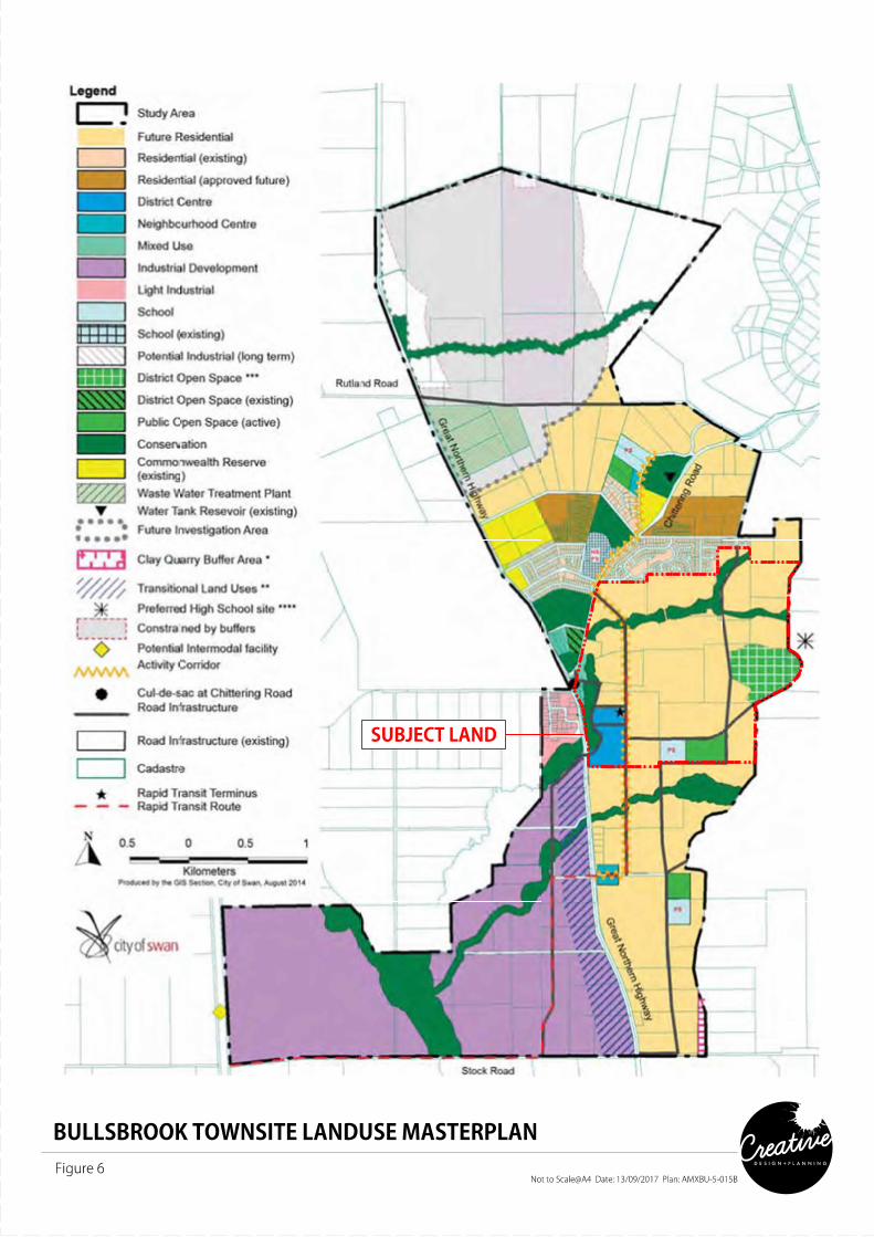
1.3.3.2 CITY OF SWAN BULLSBROOK TOWNSITE LANDUSE MASTERPLAN
The Bullsbrook Townsite Land Use Master Plan (BTLUMP), provides a strategy for the future development of Bullsbrook Townsite and has been used as a base to guide design of the Structure Plan and allocation of land uses.
The BTLUMP proposes the Structure Plan area be developed for urban purposes as a mix of ‘District Centre’, ‘Future Residential’, ‘Conservation’, ‘District Open Space’, ‘Mixed Use’, ‘Public Open Space’ and ‘Primary School’, as well as a ‘Rapid Transit Route’ and ‘Rapid Transit Route Terminus’ (Figure 6 refers). The land use designations prescribed by the BTLUMP have been generally reflected by the Structure Plan. Further detailed is provided in Section 3.7 where the Structure Plan proposes departures from the BTLUMP.
1.3.4 RELEVANT LOCAL GOVERNMENT PLANNING POLICIES & STRATEGIES
A number of Local Planning Policies and strategies have been taken into account of part of the Structure planning process, these include but are not limited to:
• Local Biodiversity Strategy• Play Space Strategy• Sustainable Environment Strategy• Transport Strategy• Water Action Plan Strategy• Urban Growth Policy• Environmental Planning Policy• Public Open Space – Residential Development Policy• Inclusion of Pedestrian Access Ways in Residential
Subdivisions Policy• Neighbourhood Planning Policy• Medium Density Single House Development Standards
(R-MD Codes)
17
ROBERTSDAY AND CREATIVE DESIGN + PLANNING BULLSBROOK CENTRAL STRUCTURE PLAN
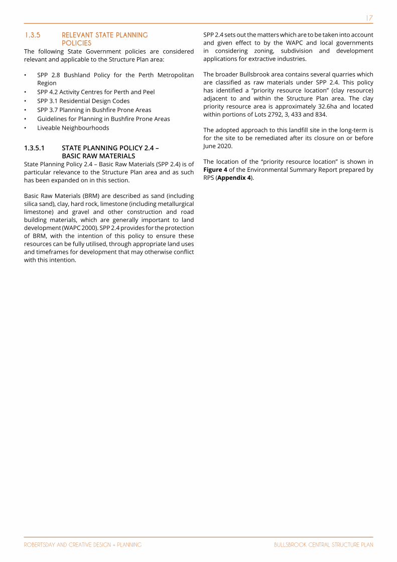
1.3.5 RELEVANT STATE PLANNING POLICIES
The following State Government policies are considered relevant and applicable to the Structure Plan area:
• SPP 2.8 Bushland Policy for the Perth Metropolitan Region
• SPP 4.2 Activity Centres for Perth and Peel• SPP 3.1 Residential Design Codes• SPP 3.7 Planning in Bushfire Prone Areas• Guidelines for Planning in Bushfire Prone Areas• Liveable Neighbourhoods
1.3.5.1 STATE PLANNING POLICY 2.4 – BASIC RAW MATERIALS
State Planning Policy 2.4 – Basic Raw Materials (SPP 2.4) is of particular relevance to the Structure Plan area and as such has been expanded on in this section.
Basic Raw Materials (BRM) are described as sand (including silica sand), clay, hard rock, limestone (including metallurgical limestone) and gravel and other construction and road building materials, which are generally important to land development (WAPC 2000). SPP 2.4 provides for the protection of BRM, with the intention of this policy to ensure these resources can be fully utilised, through appropriate land uses and timeframes for development that may otherwise conflict with this intention.
SPP 2.4 sets out the matters which are to be taken into account and given effect to by the WAPC and local governments in considering zoning, subdivision and development applications for extractive industries.
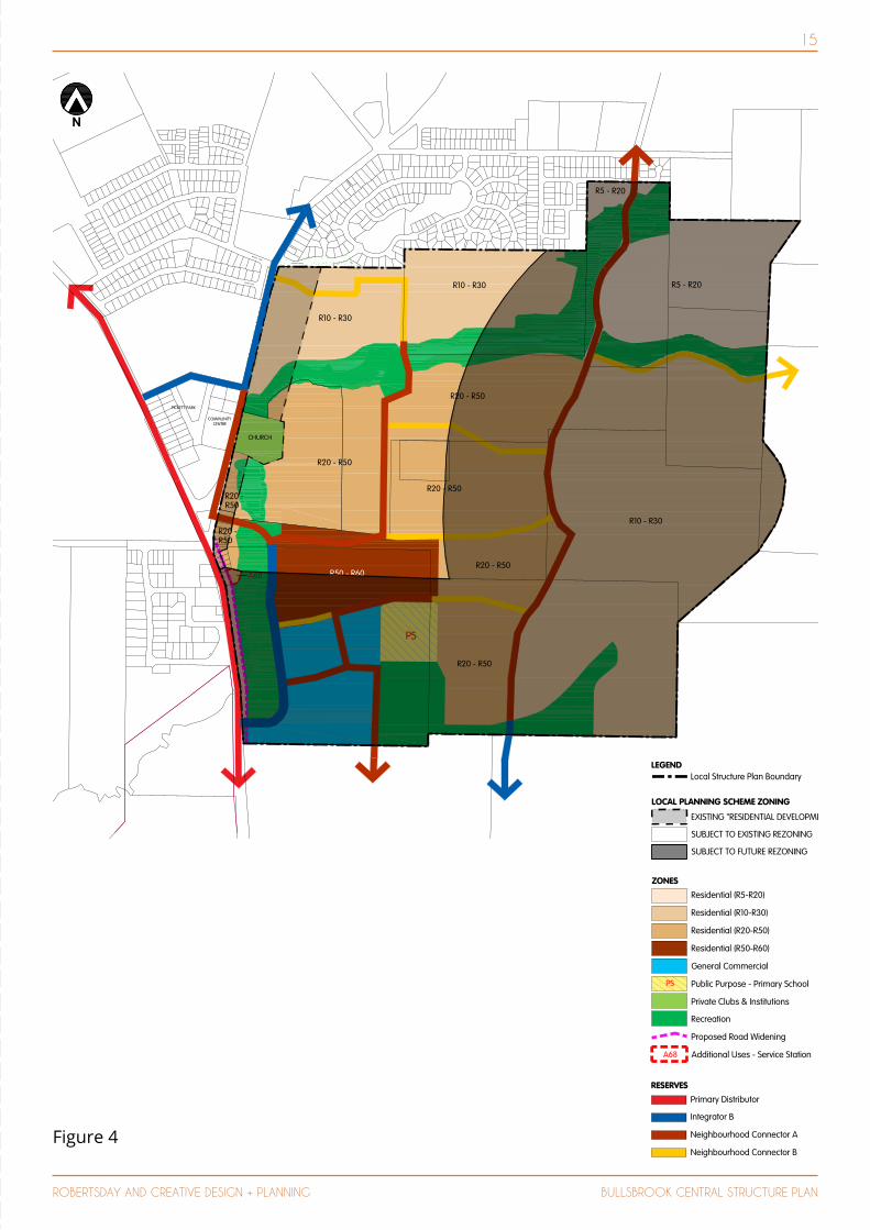
The broader Bullsbrook area contains several quarries which are classified as raw materials under SPP 2.4. This policy has identified a “priority resource location” (clay resource) adjacent to and within the Structure Plan area. The clay priority resource area is approximately 32.6ha and located within portions of Lots 2792, 3, 433 and 834.
The adopted approach to this landfill site in the long-term is for the site to be remediated after its closure on or before June 2020.
The location of the “priority resource location” is shown in Figure 4 of the Environmental Summary Report prepared by RPS (Appendix 4).

18
ROBERTSDAY AND CREATIVE DESIGN + PLANNING BULLSBROOK CENTRAL STRUCTURE PLAN
19
ROBERTSDAY AND CREATIVE DESIGN + PLANNING BULLSBROOK CENTRAL STRUCTURE PLAN
20
ROBERTSDAY AND CREATIVE DESIGN + PLANNING BULLSBROOK CENTRAL STRUCTURE PLAN
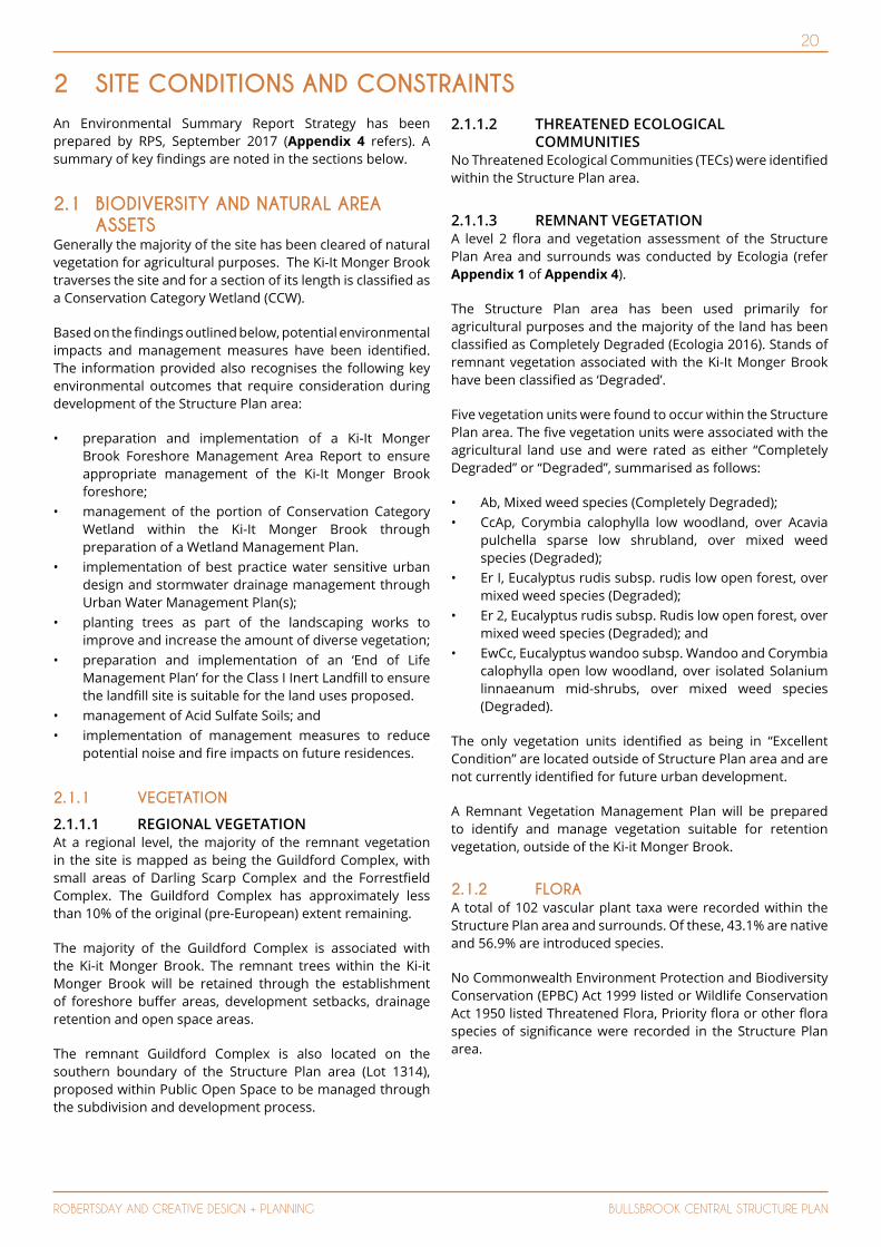
An Environmental Summary Report Strategy has been prepared by RPS, September 2017 (Appendix 4 refers). A summary of key findings are noted in the sections below.
2.1 BIODIVERSITY AND NATURAL AREA ASSETS
Generally the majority of the site has been cleared of natural vegetation for agricultural purposes. The Ki-It Monger Brook traverses the site and for a section of its length is classified as a Conservation Category Wetland (CCW).
Based on the findings outlined below, potential environmental impacts and management measures have been identified. The information provided also recognises the following key environmental outcomes that require consideration during development of the Structure Plan area:
• preparation and implementation of a Ki-It Monger Brook Foreshore Management Area Report to ensure appropriate management of the Ki-It Monger Brook foreshore;
• management of the portion of Conservation Category Wetland within the Ki-It Monger Brook through preparation of a Wetland Management Plan.
• implementation of best practice water sensitive urban design and stormwater drainage management through Urban Water Management Plan(s);
• planting trees as part of the landscaping works to improve and increase the amount of diverse vegetation;
• preparation and implementation of an ‘End of Life Management Plan’ for the Class I Inert Landfill to ensure the landfill site is suitable for the land uses proposed.
• management of Acid Sulfate Soils; and • implementation of management measures to reduce
potential noise and fire impacts on future residences.
2.1.1 VEGETATION
2.1.1.1 REGIONAL VEGETATIONAt a regional level, the majority of the remnant vegetation in the site is mapped as being the Guildford Complex, with small areas of Darling Scarp Complex and the Forrestfield Complex. The Guildford Complex has approximately less than 10% of the original (pre-European) extent remaining.
The majority of the Guildford Complex is associated with the Ki-it Monger Brook. The remnant trees within the Ki-it Monger Brook will be retained through the establishment of foreshore buffer areas, development setbacks, drainage retention and open space areas.
The remnant Guildford Complex is also located on the southern boundary of the Structure Plan area (Lot 1314), proposed within Public Open Space to be managed through the subdivision and development process.
2.1.1.2 THREATENED ECOLOGICAL COMMUNITIES
No Threatened Ecological Communities (TECs) were identified within the Structure Plan area.
2.1.1.3 REMNANT VEGETATION A level 2 flora and vegetation assessment of the Structure Plan Area and surrounds was conducted by Ecologia (refer Appendix 1 of Appendix 4).
The Structure Plan area has been used primarily for agricultural purposes and the majority of the land has been classified as Completely Degraded (Ecologia 2016). Stands of remnant vegetation associated with the Ki-It Monger Brook have been classified as ‘Degraded’.
Five vegetation units were found to occur within the Structure Plan area. The five vegetation units were associated with the agricultural land use and were rated as either “Completely Degraded” or “Degraded”, summarised as follows:
• Ab, Mixed weed species (Completely Degraded);• CcAp, Corymbia calophylla low woodland, over Acavia
pulchella sparse low shrubland, over mixed weed species (Degraded);
• Er I, Eucalyptus rudis subsp. rudis low open forest, over mixed weed species (Degraded);
• Er 2, Eucalyptus rudis subsp. Rudis low open forest, over mixed weed species (Degraded); and
• EwCc, Eucalyptus wandoo subsp. Wandoo and Corymbia calophylla open low woodland, over isolated Solanium linnaeanum mid-shrubs, over mixed weed species (Degraded).
The only vegetation units identified as being in “Excellent Condition” are located outside of Structure Plan area and are not currently identified for future urban development.
A Remnant Vegetation Management Plan will be prepared to identify and manage vegetation suitable for retention vegetation, outside of the Ki-it Monger Brook.
2.1.2 FLORAA total of 102 vascular plant taxa were recorded within the Structure Plan area and surrounds. Of these, 43.1% are native and 56.9% are introduced species.
No Commonwealth Environment Protection and Biodiversity Conservation (EPBC) Act 1999 listed or Wildlife Conservation Act 1950 listed Threatened Flora, Priority flora or other flora species of significance were recorded in the Structure Plan area.
2 SITE CONDITIONS AND CONSTRAINTS

21
ROBERTSDAY AND CREATIVE DESIGN + PLANNING BULLSBROOK CENTRAL STRUCTURE PLAN
A literature review identified one Threatened flora taxon, Acacia anomala that has previously been recorded in Bush Forever No. 86 site located to the north-east of the Structure Plan Area. Based on historical land use, vegetation units mapped and condition, this species is considered likely to occur within the Bush Forever No.86 area but not within the Structure Plan area.
2.1.3 BUSH FOREVER The Structure Plan area is in close proximity on its northern site boundary (within Lot 857) to Bush Forever Site No. 86.
The Bush Forever site is some 43ha of bushland associated with regionally significant vegetation and fauna habitat, including black cockatoo foraging and roosting habitat.
The vegetation within Bush Forever Site No. 86 includes Eucalyptus accedens, E wandoo woodlands, E wandoo, C. calophylla and E. marginata Open Forest to woodland with Allocasuarina humilis and Calytrix angulata (Government of Western Australia, 2000).
2.1.4 FAUNA The Structure Plan area exhibits a high level of disturbance from historic clearing of native vegetation and mostly comprises cleared agricultural paddocks. Consequently, it is highly unlikely that these areas provide suitable habitat for significant fauna species.
Potential habitat that does remain within the Structure Plan area includes intermittent remnant native vegetation along the Ki-it Monger Brook. The creek line also allows for the movement of native fauna from the western portion of the site to areas of larger remnant vegetation to the east.
Consequently, through retention of vegetation within Ki-it Monger Brook the majority of the limited existing habitat within the Structure Plan area will be retained. Additionally, preservation of the adjacent Bush Forever site No. 86 north-east of the Structure Plan area will assist with retaining fauna habitat.
Based on the fauna habitats remaining within the Structure Plan area, the key species that could potentially be impacted through development of the site are listed below:
• Scattered stands, or individual Eucalyptus rudis trees within the creek lines:
Κ Forest Red-tailed Black Cockatoo (Calyptorhynchus banksii naso)
Κ Carnaby’s Black Cockatoo (Calyptorhynchus latirostris) Κ Baudin’s Black Cockatoo (Calyptorhynchus baudinii).
• The banks of the seasonal creek line may support the following migratory bird species:
Κ Rainbow Bee-eater (Merops ornatus) – migratory
The proposed management and use of the Ki-it Monger Brook and water features on the site (dams) will replicate the pre-development conditions associated with both surface and groundwater availability to the existing vegetation. Therefore avifauna, in particular rainbow bee-eaters, can continue to utilise the creek area and the surrounding buffer after seasonal rain events.
Potential habitat within the Structure Plan area for black cockatoo species comprises poor foraging quality Eucalyptus rudis trees within the creek line and the occasional marri tree. These trees will be preserved in the Ki-it Monger Brook and the location of the road creek crossings will be selected to minimise the impacts to the existing mature trees.
Fauna habitat outside of the Structure Plan area (Bush Forever Site No.86) comprises more intact vegetation structure and potentially provides fauna habitat for the Carnaby’s Black-Cockatoo (Calyptorhynchus latirostris) and Baudin’s Black Cockatoo (Calyptorhynchus baudinii).
The Structure Plan responds to the objectives outlined in EPA Bulletin No. 20 Protection of natural areas through planning and development (EPA 2013).
2.2 LANDFORM AND SOILS 2.2.1 TOPOGRAPHY The Structure Plan area is located at the foothills of the Darling Scarp and is generally of high relief. The Structure Plan area ranges in elevation from approximately 120 metres Australian Height Datum (m AHD) in the east, where the foothills begin down to approximately 50m AHD to the south-west, where the relatively flat landscape of the Swan Coastal Plain commences (refer Figure 7).
2.2.2 REGIONAL GEOMORPHOLOGYThe majority of the Structure Plan area is composed of Silty Sands that are described as strong brown, firm, friable and dispersive in parts. The eastern section of the site includes Siltstone whilst the south-western boundary is dominated by Pebbly silt associated with the Guildford Formation.
Two small sections of the Structure Plan area on the eastern boundary has been mapped as granite.
2.2.3 ACID SULPHATE SOILS The Department of Environment and Regulation (DER) has compiled broad-scale mapping of the risk of acid sulphate soils for regions of Western Australia. The Structure Plan area has not been assigned an Acid Sulfate Soils (ASS) risk rating and it is assumed there is a “low to no” known risk of ASS occurring within 3m of the natural soil surface (or deeper).

22
ROBERTSDAY AND CREATIVE DESIGN + PLANNING BULLSBROOK CENTRAL STRUCTURE PLAN

23
ROBERTSDAY AND CREATIVE DESIGN + PLANNING BULLSBROOK CENTRAL STRUCTURE PLAN
2.3 GROUNDWATER AND SURFACE WATER2.3.1 GROUNDWATER The Structure Plan area is located within the Bandy Spring Sub-area of the Swan Groundwater Area and is managed under the Gnangara Groundwater Areas Allocation Plan. The Bandy Spring Sub-area contains the Superficial Aquifer and Fractured Rock West Aquifer. A review of allocation limits identified that the Superficial Aquifer was fully allocated. The Fractured Rock West Aquifer is not expected to provide significant yields. The confirmed aquifers of the Swan Confined Groundwater sub-area (Leederville and Yarragadee North aquifers) extend beneath the western section of the site, which are also fully allocated.
Through consultation with the Department of Water (DoW) and the City of Swan, it was agreed that groundwater could be abstracted from the Superficial Aquifer in the adjacent Cockman Bluff Sub-area and piped across the sub-area boundary to the development site to service its irrigation requirements.
The Structure Plan area is not located within a Public Drinking Water Source Protection area.
2.3.1.1 REGIONAL GROUNDWATER LEVELSRegional groundwater mapping by the Department of Water indicates groundwater migrates towards Ellen Brook, located approximately 2.3 km to the west. In the Perth Groundwater Atlas the May 2003 groundwater contours just extend onto the western boundary of the Structure Plan area and range from 50 m AHD in the north to 45 m AHD in the south.
2.3.1.2 SITE GROUNDWATER LEVELS In September 2015, six monitoring bores were installed across the Structure Plan area. Drilling generally occurred to a depth of 18 mbgl. The locations of the bores are shown in Figure 6 of the LWMS (Appendix 5).
Groundwater levels were monitored from these bores and three other bores that existed on the site on two occasions in September and October 2015, and then again in November 2016. Two of the bores were dry on all occasions, while the depth to water measured from the other bores ranged from 1.08 metres below top of casing (mbtoc) to 17.51 m btoc.
Groundwater contours have been generated from the October monitoring event, ranging from 75 m AHD to 30 m AHD. Groundwater levels monitored from the bores ranged from 30.49 m AHD to 77.89 m AHD. All monitoring results are provided in Appendix 4 of the LWMS (Appendix 5).
Due to the significant depth to groundwater over the majority of the site, a complete 18 month groundwater monitoring program (covering two winter peaks) has not been undertaken. The only two bores with relatively shallow groundwater levels are located near a dam at the landfill facility and the Ki-it Monger Brook respectively and hence it is interpreted the groundwater levels are influenced by localised water conditions.
2.3.1.3 GROUNDWATER QUALITY Field-measured groundwater pH below the site ranged from acidic to slightly acidic. Nutrient concentrations were found to be elevated, in particular TN and TP. The concentration of TN and TP were above the ANZECC (2000) guidelines for lowland rivers in south-west.
2.3.2 SURFACE WATER The key water feature of the Structure Plan area is Ki-It Monger Brook which flows east to west across the northern part of the Structure Plan area. It then runs along the south side of the site, before crossing under Great Northern Highway at the site’s south-west corner, until it confluences with Ellen Brook approximately 2.3km south-west of the site. A number of smaller drainage tributaries contribute to the Ki-it Monger Brook including a minor unnamed drainage course that traverses the southern section of the site and discharges into Ki-it Monger Brook near the site’s south-west corner.
The Ki-it Monger Brook has been considerably modified including the constriction of dams and installation of culverts on the site which restrict flows as well as the clearing of riparian vegetation. In particular, a major dam located in the centre of the site has a major impact on flows downstream, as flows only occur once the water level reaches the height of the culverts installed in the dam wall.
2.3.3 WETLANDS AND WATERWAYSThe Structure Plan area includes two wetlands that occur within sections of the Ki-it Monger Brook; one is classified as a Conservation Category Wetland (CCW) (UFI 12681) and one is a Multiple Use Wetland (MUW) which is likely to have few important ecological attributes and functions remaining.
A botanical assessment was conducted detailing the spatial extent and characteristics of the wetlands within the Structure Plan area, in particular the CCW (UFI 12681). There were no significant flora species recorded or likely to occur along Ki-it Monger Brook.
Both the CCW and MUW within Ki-it Monger Brook had vegetation condition rated as ‘Degraded’ with no or scattered native understorey plants, litter, high grazing levels and dominated by weeds. There were no differences in the vegetation type, floristic composition, condition or values in the CCW section of the Ki-it Monger Brook, the MUW section or the un-classified section (i.e. parts of the Ki-it Monger Brook that were surveyed but are not classified as a CCW or MUW).
Based on the current biophysical condition of Ki-it Monger Brook within the Structure Plan area, it is proposed to retain the foreshore area to the extent of the banks for the majority of the site. The width of the foreshore area will vary along its extent, ranging from approximately 120m at its widest and 10m at the narrowest point, incorporating both sides of the bank.
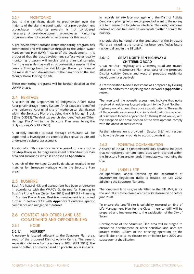
24
ROBERTSDAY AND CREATIVE DESIGN + PLANNING BULLSBROOK CENTRAL STRUCTURE PLAN
2.3.4 MONITORING Due to the significant depth to groundwater over the majority of the site, the continuation of a pre-development groundwater monitoring program is not considered necessary. A post-development groundwater monitoring program is also not considered necessary for this reason.
A pre-development surface water monitoring program has commenced and will continue through to the Urban Water Management Plan (UWMP) stage of the development. It is proposed that the post-development surface water quality monitoring program will involve taking biannual samples from the main dam as well as opportunistic samples (if the creek is flowing) from the Ki-it Monger Brook upstream of the main dam and downstream of the dam prior to the Ki-it Monger Brook leaving the site.
These monitoring programs will be further detailed at the UWMP phase.
2.4 HERITAGEA search of the Department of Indigenous Affairs (DIA) Aboriginal Heritage Inquiry System (AHIS) database identified one registered Aboriginal site of mythological significance within the Structure Plan area, being the Ki-It Monger Brook 2 (Site ID 3583). The desktop search also identified one ‘Other Heritage Place’ within the Structure Plan area, being the Bullya Spring (Site ID 22669).
A suitably qualified cultural heritage consultant will be appointed to investigate the extent of the registered site and undertake a cultural assessment.
Additionally, Ethnosciences were engaged to carry out a desktop Aboriginal heritage assessment of the Structure Plan area and surrounds, which is enclosed as Appendix 6.
A search of the Heritage Council’s database resulted in no matches for European Heritage within the Structure Plan area.
2.5 BUSHFIREBush fire hazard risk and assessment has been undertaken in accordance with the WAPC’s Guidelines for Planning in Bushfire Prone Areas (December 2015) and SPP 3.7 – Planning in Bushfire Prone Areas. Bushfire management is explored further in Section 3.2.2 with Appendix 1 outlining specific compliance and mitigation measures.
2.6 CONTEXT AND OTHER LAND USE CONSTRAINTS AND OPPORTUNITIES
2.6.1 NOISE
2.6.1.1 NURSERY A nursery is located adjacent to the Structure Plan area, south of the proposed District Activity Centre. The generic separation distance from a nursery is 100m (EPA 2015). The generic buffer is primarily based on potential noise impacts.
In regards to interface management, the District Activity Centre and playing fields are proposed adjacent to the nursey site to manage the long-term interface. The design outcome ensures no sensitive land uses are located within 100m of the nursery.
It should also be noted that the land south of the Structure Plan area (including the nursery) has been identified as future residential land in the BTLUMP.
2.6.1.2 GREAT NORTHERN HIGHWAY & CHITTERING ROAD
Great Northern Highway and Chittering Road are located adjacent to the Structure Plan area, west of the proposed District Activity Centre and west of proposed residential development respectively.
A Transportation Noise Assessment was prepared by Herring Storer to address the adjoining road networks (Appendix 2 refers).
The results of the acoustic assessment indicate that noise received at residences located adjacent to the Great Northern Highway would exceed the above acoustic criteria. The results of the acoustic assessment also indicated that noise received at residences located adjacent to Chittering Road would, with the exception of a small section of the development, comply with the above acoustic criteria
Further information is provided in Section 3.2.1 with respect to how the design responds to acoustic constraints.
2.6.2 POTENTIAL CONTAMINATION A search of the DER’s Contaminated Sites database indicates that no registered contaminated sites were recorded within the Structure Plan area or lands immediately surrounding the site.
2.6.3 LANDFILL SITE An operational landfill licensed by the Department of Environment Regulation (DER) is located on Lot 2792, adjoining the Structure Plan area.
The long-term land use, as identified in the BTLUMP, is for the landfill site to be remediated after its closure on or before June 2020.
To ensure the landfill site is suitability restored an ‘End of Life Management Plan for the Class I Inert Landfill’ will be prepared and implemented to the satisfaction of the City of Swan.
Development of the Structure Plan area will be staged to ensure no development or other sensitive land uses are located within 1,000m of the crushing operation on the landfill site prior to its closure on or before June 2020 and subsequent rehabilitation.
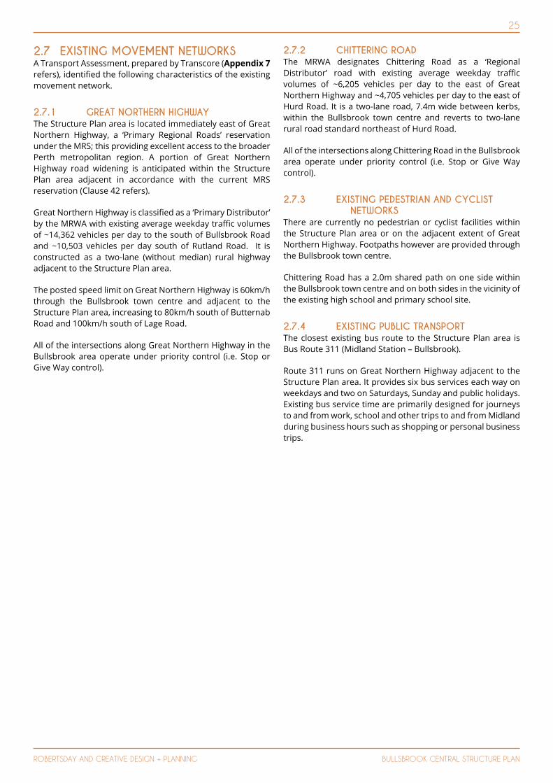
25
ROBERTSDAY AND CREATIVE DESIGN + PLANNING BULLSBROOK CENTRAL STRUCTURE PLAN
2.7 EXISTING MOVEMENT NETWORKS A Transport Assessment, prepared by Transcore (Appendix 7 refers), identified the following characteristics of the existing movement network.
2.7.1 GREAT NORTHERN HIGHWAYThe Structure Plan area is located immediately east of Great Northern Highway, a ‘Primary Regional Roads’ reservation under the MRS; this providing excellent access to the broader Perth metropolitan region. A portion of Great Northern Highway road widening is anticipated within the Structure Plan area adjacent in accordance with the current MRS reservation (Clause 42 refers).
Great Northern Highway is classified as a ‘Primary Distributor’ by the MRWA with existing average weekday traffic volumes of ~14,362 vehicles per day to the south of Bullsbrook Road and ~10,503 vehicles per day south of Rutland Road. It is constructed as a two-lane (without median) rural highway adjacent to the Structure Plan area.
The posted speed limit on Great Northern Highway is 60km/h through the Bullsbrook town centre and adjacent to the Structure Plan area, increasing to 80km/h south of Butternab Road and 100km/h south of Lage Road.
All of the intersections along Great Northern Highway in the Bullsbrook area operate under priority control (i.e. Stop or Give Way control).
2.7.2 CHITTERING ROADThe MRWA designates Chittering Road as a ‘Regional Distributor’ road with existing average weekday traffic volumes of ~6,205 vehicles per day to the east of Great Northern Highway and ~4,705 vehicles per day to the east of Hurd Road. It is a two-lane road, 7.4m wide between kerbs, within the Bullsbrook town centre and reverts to two-lane rural road standard northeast of Hurd Road.
All of the intersections along Chittering Road in the Bullsbrook area operate under priority control (i.e. Stop or Give Way control).
2.7.3 EXISTING PEDESTRIAN AND CYCLIST NETWORKS
There are currently no pedestrian or cyclist facilities within the Structure Plan area or on the adjacent extent of Great Northern Highway. Footpaths however are provided through the Bullsbrook town centre.
Chittering Road has a 2.0m shared path on one side within the Bullsbrook town centre and on both sides in the vicinity of the existing high school and primary school site.
2.7.4 EXISTING PUBLIC TRANSPORTThe closest existing bus route to the Structure Plan area is Bus Route 311 (Midland Station – Bullsbrook).
Route 311 runs on Great Northern Highway adjacent to the Structure Plan area. It provides six bus services each way on weekdays and two on Saturdays, Sunday and public holidays. Existing bus service time are primarily designed for journeys to and from work, school and other trips to and from Midland during business hours such as shopping or personal business trips.
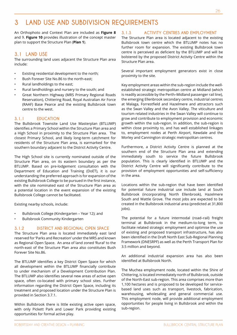
26
ROBERTSDAY AND CREATIVE DESIGN + PLANNING BULLSBROOK CENTRAL STRUCTURE PLAN
An Orthophoto and Context Plan are included as Figure 8 and 9. Figure 10 provides illustration of the concept master plan to support the Structure Plan (Plan 1).
3.1 LAND USEThe surrounding land uses adjacent the Structure Plan area include:
• Existing residential development to the north;• Bush Forever Site No.86 to the north-east;• Rural landholdings to the east;• Rural landholdings and nursery to the south; and• Great Northern Highway (MRS Primary Regional Roads
Reservation), Chittering Road, Royal Australian Air Force (RAAF) Base Pearce and the existing Bullsbrook town centre to the west.
3.1.1 EDUCATIONThe Bullsbrook Townsite Land Use Masterplan (BTLUMP) identifies a Primary School within the Structure Plan area and a High School in proximity to the Structure Plan area. The closest Primary School, and likely long-term catchment for residents of the Structure Plan area, is earmarked for the southern boundary adjacent to the District Activity Centre.
The High School site is currently nominated outside of the Structure Plan area, on its eastern boundary as per the BTLUMP. Based on pre-lodgement consultation with the Department of Education and Training (DoET), it is our understanding the preferred approach is for expansion of the existing Bullsbrook College to be pursued in the first instance, with the site nominated east of the Structure Plan area as a potential location in the event expansion of the existing Bullsbrook College cannot be facilitated.
Existing nearby schools, include:
• Bullsbrook College (Kindergarten – Year 12); and• Bullsbrook Community Kindergarten
3.1.2 DISTRICT AND REGIONAL OPEN SPACE The Structure Plan area is located immediately east land reserved for ‘Parks and Recreation’ under the MRS and known as Regional Open Space. An area of land zoned ‘Rural’ to the north-east of the Structure Plan area also constitutes Bush Forever Site No.86.
The BTLUMP identifies a key District Open Space for which all development within the BTLUMP financially contribute to under mechanism of a Development Contribution Plan. The BTLUMP also identifies several new areas of active open space, often co-located with primary school sites. Further information regarding the District Open Space, including its treatment and proposed location under the Structure Plan is provided in Section 3.7.1.
Within Bullsbrook there is little existing active open space, with only Pickett Park and Lower Park providing existing opportunities for formal active play.
3.1.3 ACTIVITY CENTRES AND EMPLOYMENTThe Structure Plan area is located adjacent to the existing Bullsbrook town centre which the BTLUMP notes has no further room for expansion. The existing Bullsbrook town centre is perceived as deficient by the BTLUMP and will be bolstered by the proposed District Activity Centre within the Structure Plan area.
Several important employment generators exist in close proximity to the site.
Key employment areas within the sub-region include the well-established strategic metropolitan centre at Midland (which is readily accessible by the Perth–Midland passenger rail line), the emerging Ellenbrook secondary centre, industrial centres at Malaga, Forrestfield and Hazelmere and attractors such as the Swan Valley and the Avon Valley. The viticulture and tourism related industries in the Swan Valley will continue to grow and contribute to employment provision and economic growth within the sub-region. In addition, the sub-region is within close proximity to, and has well established linkages to, employment nodes at Perth Airport, Kewdale and the Morley and Cannington strategic metropolitan centres.
Furthermore, a District Activity Centre is planned at the southern end of the Structure Plan area and extending immediately south to service the future Bullsbrook population. This is clearly identified in BTLUMP and the District Activity Centre will significantly contribute to the provision of employment opportunities and self-sufficiency in the area.
Locations within the sub-region that have been identified for potential future industrial use include land at South Bullsbrook (incorporating North Ellenbrook), Hazelmere South and Wattle Grove. The most jobs are expected to be created in the Bullsbrook industrial area (predicted at 31,800 jobs).
The potential for a future intermodal (road–rail) freight terminal at Bullsbrook in the medium-to-long term, to facilitate related strategic employment and optimise the use of existing and proposed transport infrastructure, has also been identified in the Draft North East Sub-Regional Planning Framework (DNESRPF) as well as the Perth Transport Plan for 3.5 million and beyond.
An additional industrial expansion area has also been identified at Bullsbrook North.
The Muchea employment node, located within the Shire of Chittering, is located immediately north of Bullsbrook, outside of the North-East sub-region. This area comprises more than 1,100 hectares and is proposed to be developed for service-based land uses such as transport, livestock, fabrication, warehousing, wholesaling and general commercial use. This employment node, will provide additional employment opportunities for people living in Bullsbrook and within the sub-region.
3 LAND USE AND SUBDIVISION REQUIREMENTS

27
ROBERTSDAY AND CREATIVE DESIGN + PLANNING BULLSBROOK CENTRAL STRUCTURE PLAN
3.1.4 COMMUNITY FACILITIESThe Bullsbrook locality is currently well serviced with community facilities including community halls, a library, a sports club, child health care facilities, youth facilities, skate park, BMX track, hard courts, tennis courts, bridle trails and a golf club within close proximity the Structure Plan area.
Additional community facilities will be required as the Bullsbrook townsite population grows and will be included in development contribution plan(s) for the area. Some future community facilities may be accommodated within the future District Centre located within the Structure Plan area.
3.2 EXTERNAL DESIGN INFLUENCES3.2.1 ACOUSTICS & NOISE TARGETS A Transportation Noise Assessment was prepared by Herring Storer to address the adjoining regional and district road networks (Appendix 2 refers).
The assessment was undertaken in accordance with the WAPC’s State Planning Policy 5.4 – Road and Rail Transportation Noise and Freight Considerations in Land Use Planning (SPP 5.4), with the key findings as follows.
The acoustic assessment carried out for the Structure Plan area found that without mitigation, ‘noise targets’ set by SPP 5.4 would be exceeded for dwellings close to Great Northern Highway and Chittering Road. Affected areas are indicatively illustrated under Figures D1 and D2 of the Transportation Noise Assessment (Appendix 2 refers).
3.2.1.1 PEARCE RAAF BASEWith respect to potential noise from the Pearce RAAF Base, the acoustic assessment found that the development is located outside the Australian Noise Exposure Forecast (ANEF) 20 contour. Hence, residential development without any requirement for noise amelioration, is acceptable within this development.
3.2.1.2 GREAT NORTHERN HIGHWAYTo mitigate the noise impacts for Great Northern Highway, two design options are provided:
• An access road be constructed between the first row of residences and Great Northern Highway, such that residences front Great Northern Highway. ‘Quiet House’ Design is required for the ‘first row’ of dwellings fronting Great Northern Highway.
• If the first row of residences to the Great Northern Highway is located at or outside the 60 dB(A) contour, then with the inclusion of a 2 metre highback fence, residences may back on to Great Northern Highway (i.e. back yards to the Great Northern Highway). To then achieve compliance “Quiet House” design requirements as outlined for either Packages “A” or “B” would be required, depending on dwelling setbacks.
All affected residential lots will require a notification on Title where noise targets are exceeded.
3.2.1.3 CHITTERING ROADThe results of the acoustic assessment indicate that noise received at residences located adjacent to Chittering Road would, with the exception of a small section of the development, comply with the above acoustic criteria. Apart from this small section where development could occur within the 55 dB(A) contour, there are no acoustic requirements.
For the section of the development within the 55 dB(A) contour, standard construction would be acceptable and only notification on titles would be required.
The recommendations above for both Great Northern Highway and Chittering Road are made for single storey dwellings. Specialist acoustic advice should be sought for double storey dwellings.
3.2.2 BUSH FIRE MANAGEMENTA Bushfire Management Plan (BMP) has been prepared by Strategen (Appendix 1 refers); this report prepared in accordance with the WAPC’s Guidelines for Planning in Bushfire-Prone Areas 2015, and SPP 3.7: Planning in Bushfire Prone Areas, and the Australian Standard AS3959-2009 Construction of buildings in bushfire prone areas (AS3959) (Standards Australia 2009).
The assessment of the existing vegetation within the Structure Plan area (Figure 4 of Appendix 1) identified that vegetation within the Ki-It Monger Brook foreshore area and internal Conservation Category Wetland (CCW) on Lot 1354 Great Northern Highway as permanent extreme bushfire hazard considerations. The adjacent Bush Forever Site No.86 was also identified as an ‘extreme’ bushfire hazard. All other woodland, shrubland and grassland within the Structure Plan area were assigned ‘moderate’ levels of bushfire hazard.
With respect to the post-development scenario, the BMP takes a precautionary approach to the allocation of bushfire hazard levels. As such, the ‘extreme’ and ‘moderate’ levels of bushfire hazard identified in the pre-development assessment remain consistent in the post-development assessment with the exception of cleared areas which represent a ‘low’ bushfire hazard.
The post-development scenario will be revisited at the subdivision stage where further detailed landscaping and lot layouts will be available.
It should be noted that where of dwellings are within 100m of vegetation assessed as having ‘extreme’ or ‘moderate’ bushfire hazard level implementation of increased building construction standards may be required.
The proposed movement network (explored further in Section 3.14) appropriately satisfies the requirements of the Guidelines for Planning in Bushfire Prone Areas with suitable linkages proposed to future and existing development on adjacent landholdings. Two primary north-south linkages traverse the Structure Plan area, ensuring all residents and visitors of the development are provided with at least two vehicular access routes connecting to the surrounding pubic network at all times. In total, five significant access and egress points are proposed by the Structure Plan.

28
ROBERTSDAY AND CREATIVE DESIGN + PLANNING BULLSBROOK CENTRAL STRUCTURE PLAN

29
ROBERTSDAY AND CREATIVE DESIGN + PLANNING BULLSBROOK CENTRAL STRUCTURE PLAN

30
CREATIVE DESIGN + PLANNING BULLSBROOK CENTRAL STRUCTURE PLAN
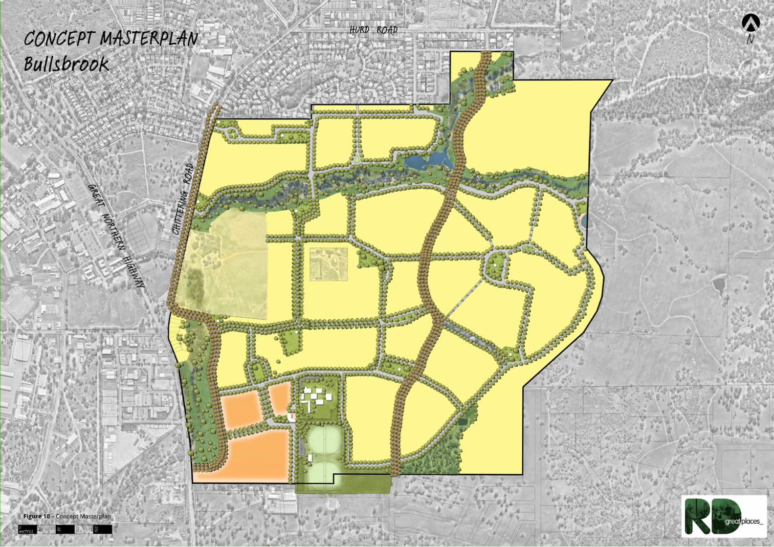
Figure 10 – Concept Masterplan


33
ROBERTSDAY AND CREATIVE DESIGN + PLANNING BULLSBROOK CENTRAL STRUCTURE PLAN
THIS PAGE HAS BEEN INTENTIONALLY LEFT BLANK

34
ROBERTSDAY AND CREATIVE DESIGN + PLANNING BULLSBROOK CENTRAL STRUCTURE PLAN
CHITTERING
ROAD
GR
EA
T
HW
Y
NO
RT
HE
RN
3.3 DESIGN PHILOSOPHYThe Structure Plan design has taken into consideration the environmental and physical attributes within and external to the site, as well as acknowledging abutting land uses and how these can best be addressed with regard to interfacing with future residential land uses.
The design philosophy has been predicated upon the following objectives:
• to provide a range of residential densities according with the density targets of Directions 2031 to encourage diversity of lot product, built form and affordability measures;
• to provide suitable interface to the MRS Primary Regional Roads reservation to address noise mitigation;
• to provide suitable interface to external boundaries and internal remnant vegetated areas where the threat of fire requires mitigation;
• provide suitable location and amenity within public open space areas to ensure accessibility, visual aesthetics and view corridors to foster a local sense of identity and community for specific internal ‘precincts’ as well as the Structure Plan area as a whole;
• to deliver a safe pedestrian and cyclist environment with pathways linking residential precincts and associated local parks as well as providing for external connectivity to strategic community nodes; and
• to implement sound engineering and drainage solutions for the Structure Plan area.
• In response to the above objectives, the Structure Plan proposes an urban layout utilising an interconnected road network and open space system which embraces the existing landform and amenity, including the Ki-It Monger Brook. The Structure Plan has been designed in a manner to encourage safe pedestrian movements within the site, and to connect to regional infrastructure en route to various City of Swan community nodes.
3.4 OPPORTUNITIES AND CONSTRAINTS Located at the base of the Darling Scarp foothills, the Structure Plan area presents immense opportunities to create an incredibly distinct urban village. Beyond the dramatic backdrop and varied views, a myriad of other opportunities exist in response to undulating landform.
The heavily vegetated Ki It Monger Brook is a stunning natural asset and source of amenity, health, history, retreat, fun and discovery with the core creek area to be retained.
Following the south-eastern overland flow-path and connecting other existing vegetation, a Green Loop is proposed to create a contiguous 4.3km system for people and ecology to co-exist.
Major access points are consistent with the City of Swan BTLUMP, with two proposed from Chittering Road, one from Great Northern Highway, one from the south and one from the north. The Chittering Road realignment will provide the major north-south connection through the site in the form of an attractive transit boulevard.
The centrally located existing homestead will be retained on a 2ha lot and integrated into the master plan design.
Core creek area
Environmental Protection
Ki It Monger Brook
Homestead
Green loop
Site access
Chittering Road Re-alignment
Figure 11 – Opportunities and Constraints

35
ROBERTSDAY AND CREATIVE DESIGN + PLANNING BULLSBROOK CENTRAL STRUCTURE PLAN
Bushfire risk is largely associated with areas of vegetation to be retained on the site. The key areas that will be subject to bushfire management include urban land adjoining the Brook and the existing vegetation to be retained to the south east.
The landform, views and landscape character of the Structure Plan area present significant opportunities and constraints, which are addressed separately under the Sections 3.4.1 and 3.4.2 below.
A Place Vision, principles and concept master plan has been developed in response to the site opportunities and constraints identified, together with market and place analysis. This is detailed further in Section 3.5.
3.4.1 LANDFORM The landform of the site and its surrounds is unique and consists of a series of valleys and hill-tops peaking at a high point of RL 114m to the east and dropping to a low point of RL 46m to the south- west.
A site constraint presented by the landform is developing on steeper land. A substantial proportion of the site could be categorised as having moderate to steep slope of 5% or more. Whilst only a small portion of the site has in excess of 10% slope, development on steeper land will need to be sensitively designed and delivered. On steeper land generally, a combination of civil, landscape and built form solutions will be needed to address character and functional considerations.
These aspects have been taken into consideration where possible as part of the Structure Plan design.
Equally, the opportunities of developing on elevated land with views is immense. The offer of a diversity of views and character within the public realm and from private lots will make for a highly attractive address.
3.4.2 VIEWS AND LANDSCAPE The Structure Plan area offers a rich diversity of views and sense of place. There are different views internally and externally. Spatially, there are at least six distinct character areas on the site, each with a defined view shed, sense of enclosure or openness, and elevation, all of which enjoy views back to the scarp backdrop:
• Intimate middle valley featuring an elevated creek line;• Large Lower Valley with the creek line and some long
views;• Flats has views to the scarp and creek line tree tops;• Rise includes views to the scarp and creek line;• Peak is an elevated long open space and city views; and• Upper Valley is elevated with clear views down to the
creek line.
114m
46m
CHITTERING
ROAD
GR
EA
T
HW
Y
NO
RTHER
N
Figure 12 - Landform
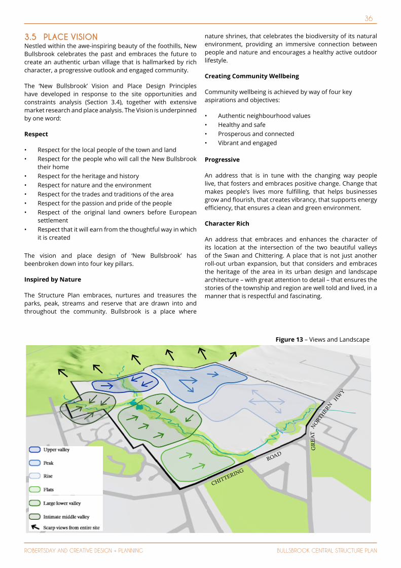
36
ROBERTSDAY AND CREATIVE DESIGN + PLANNING BULLSBROOK CENTRAL STRUCTURE PLAN
3.5 PLACE VISION Nestled within the awe-inspiring beauty of the foothills, New Bullsbrook celebrates the past and embraces the future to create an authentic urban village that is hallmarked by rich character, a progressive outlook and engaged community.
The ‘New Bullsbrook’ Vision and Place Design Principles have developed in response to the site opportunities and constraints analysis (Section 3.4), together with extensive market research and place analysis. The Vision is underpinned by one word:
Respect
• Respect for the local people of the town and land• Respect for the people who will call the New Bullsbrook
their home• Respect for the heritage and history• Respect for nature and the environment• Respect for the trades and traditions of the area• Respect for the passion and pride of the people• Respect of the original land owners before European
settlement• Respect that it will earn from the thoughtful way in which
it is created
The vision and place design of ‘New Bullsbrook’ has beenbroken down into four key pillars.
Inspired by Nature
The Structure Plan embraces, nurtures and treasures the parks, peak, streams and reserve that are drawn into and throughout the community. Bullsbrook is a place where
nature shrines, that celebrates the biodiversity of its natural environment, providing an immersive connection between people and nature and encourages a healthy active outdoor lifestyle.
Creating Community Wellbeing
Community wellbeing is achieved by way of four key aspirations and objectives:
• Authentic neighbourhood values• Healthy and safe• Prosperous and connected• Vibrant and engaged
Progressive
An address that is in tune with the changing way people live, that fosters and embraces positive change. Change that makes people’s lives more fulfilling, that helps businesses grow and flourish, that creates vibrancy, that supports energy efficiency, that ensures a clean and green environment.
Character Rich
An address that embraces and enhances the character of its location at the intersection of the two beautiful valleys of the Swan and Chittering. A place that is not just another roll-out urban expansion, but that considers and embraces the heritage of the area in its urban design and landscape architecture – with great attention to detail – that ensures the stories of the township and region are well told and lived, in a manner that is respectful and fascinating.
CHITTERING
ROAD
GR
EA
T
HW
Y
NO
RTHER
N
Figure 13 – Views and Landscape
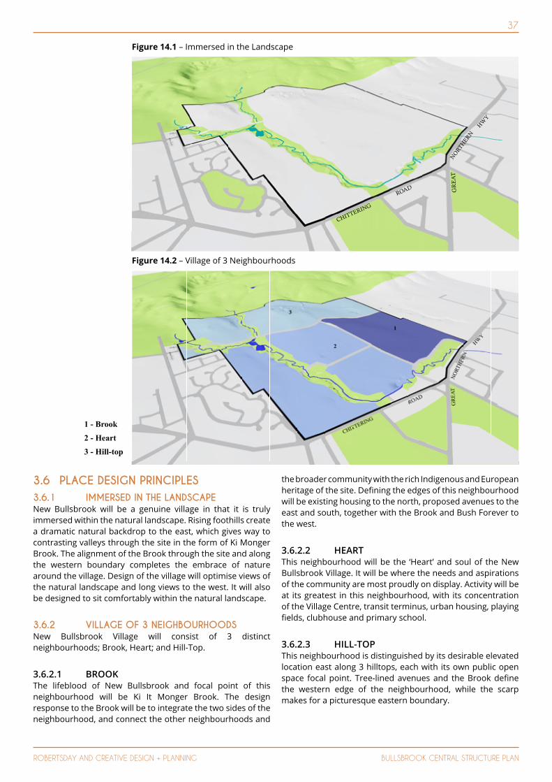
37
ROBERTSDAY AND CREATIVE DESIGN + PLANNING BULLSBROOK CENTRAL STRUCTURE PLAN
3.6 PLACE DESIGN PRINCIPLES 3.6.1 IMMERSED IN THE LANDSCAPE New Bullsbrook will be a genuine village in that it is truly immersed within the natural landscape. Rising foothills create a dramatic natural backdrop to the east, which gives way to contrasting valleys through the site in the form of Ki Monger Brook. The alignment of the Brook through the site and along the western boundary completes the embrace of nature around the village. Design of the village will optimise views of the natural landscape and long views to the west. It will also be designed to sit comfortably within the natural landscape.
3.6.2 VILLAGE OF 3 NEIGHBOURHOODSNew Bullsbrook Village will consist of 3 distinct neighbourhoods; Brook, Heart; and Hill-Top.
3.6.2.1 BROOKThe lifeblood of New Bullsbrook and focal point of this neighbourhood will be Ki It Monger Brook. The design response to the Brook will be to integrate the two sides of the neighbourhood, and connect the other neighbourhoods and
the broader community with the rich Indigenous and European heritage of the site. Defining the edges of this neighbourhood will be existing housing to the north, proposed avenues to the east and south, together with the Brook and Bush Forever to the west.
3.6.2.2 HEARTThis neighbourhood will be the ‘Heart’ and soul of the New Bullsbrook Village. It will be where the needs and aspirations of the community are most proudly on display. Activity will be at its greatest in this neighbourhood, with its concentration of the Village Centre, transit terminus, urban housing, playing fields, clubhouse and primary school.
3.6.2.3 HILL-TOPThis neighbourhood is distinguished by its desirable elevated location east along 3 hilltops, each with its own public open space focal point. Tree-lined avenues and the Brook define the western edge of the neighbourhood, while the scarp makes for a picturesque eastern boundary.
Figure 14.2 – Village of 3 Neighbourhoods
Figure 14.1 – Immersed in the Landscape
CHITTERING
ROAD G
RE
AT
HW
Y
NO
RTHER
N
1 - Brook2 - Heart3 - Hill-top

38
ROBERTSDAY AND CREATIVE DESIGN + PLANNING BULLSBROOK CENTRAL STRUCTURE PLAN
Figure 14.4 – Transit Village
Figure 14.3 – Connected by Nature
CHITTERING
ROAD G
RE
AT
HW
Y
NO
RTHER
N
CHITTERING
ROAD
GR
EA
T
NO
RT
HE
RN
HW
Y
Core creek area
Public open space
Major bus transit
Potential bus routes
3.6.3 CONNECTED BY NATUREThe New Bullsbrook community will have strong connections with nature, particularly via a ‘Green Loop’ connecting the Brook to complete a 4.2km contiguous ecological system. Walking and cycling paths set amongst avenues of existing and retained trees will provide the entire community with convenient access to the Brook, Village Centre, Playing fields and Primary School. The southern extent of the Green Loop is positioned on a meandering topographical low-point, reinforcing its natural qualities and culminating in the Village Centre where it takes on a more urban character before returning to nature. Within the Brook, the community will be able to engage with nature in various ways, without compromising ecological values.
3.6.4 TRANSIT VILLAGEThe Bullsbrook Town site will over time have good access to public transport via a Rapid Transit Service line which is intended to service the Swan Urban Growth Corridor and Ellenbrook. The New Bullsbrook site will make a significant contribution to this, with an ‘Activity Corridor’ boulevard extending north-south through the site as a realignment of Chittering Road. For the boulevard to support walking, cycling and residential frontages it will need to be designed based on leading best practice. It is proposed that a bus stop terminus would be located adjacent to the Village Centre consistent with the Land Use Master Plan.
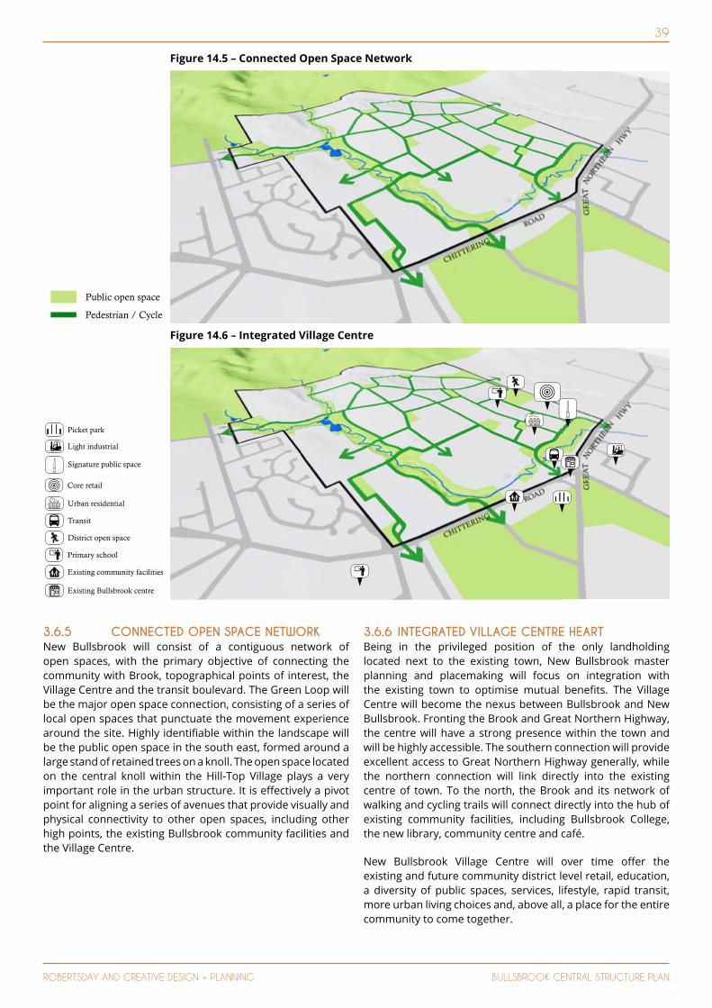
39
ROBERTSDAY AND CREATIVE DESIGN + PLANNING BULLSBROOK CENTRAL STRUCTURE PLAN
3.6.5 CONNECTED OPEN SPACE NETWORK New Bullsbrook will consist of a contiguous network of open spaces, with the primary objective of connecting the community with Brook, topographical points of interest, the Village Centre and the transit boulevard. The Green Loop will be the major open space connection, consisting of a series of local open spaces that punctuate the movement experience around the site. Highly identifiable within the landscape will be the public open space in the south east, formed around a large stand of retained trees on a knoll. The open space located on the central knoll within the Hill-Top Village plays a very important role in the urban structure. It is effectively a pivot point for aligning a series of avenues that provide visually and physical connectivity to other open spaces, including other high points, the existing Bullsbrook community facilities and the Village Centre.
3.6.6 INTEGRATED VILLAGE CENTRE HEART Being in the privileged position of the only landholding located next to the existing town, New Bullsbrook master planning and placemaking will focus on integration with the existing town to optimise mutual benefits. The Village Centre will become the nexus between Bullsbrook and New Bullsbrook. Fronting the Brook and Great Northern Highway, the centre will have a strong presence within the town and will be highly accessible. The southern connection will provide excellent access to Great Northern Highway generally, while the northern connection will link directly into the existing centre of town. To the north, the Brook and its network of walking and cycling trails will connect directly into the hub of existing community facilities, including Bullsbrook College, the new library, community centre and café.
New Bullsbrook Village Centre will over time offer the existing and future community district level retail, education, a diversity of public spaces, services, lifestyle, rapid transit, more urban living choices and, above all, a place for the entire community to come together.
Figure 14.5 – Connected Open Space Network
Picket park
Light industrial
Signature public space
Core retail
Urban residential
Transit
District open space
Primary school
Existing community facilities
Existing Bullsbrook centre
Figure 14.6 – Integrated Village Centre
Public open space
Pedestrian / Cycle
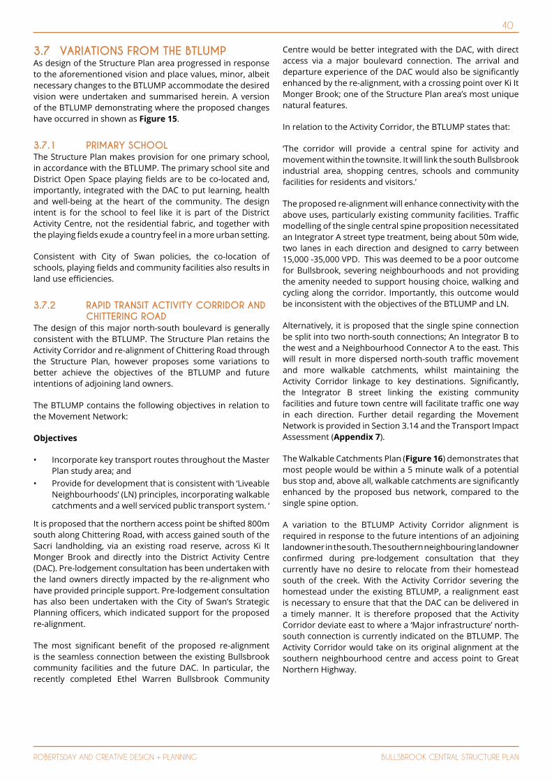
40
ROBERTSDAY AND CREATIVE DESIGN + PLANNING BULLSBROOK CENTRAL STRUCTURE PLAN
3.7 VARIATIONS FROM THE BTLUMP As design of the Structure Plan area progressed in response to the aforementioned vision and place values, minor, albeit necessary changes to the BTLUMP accommodate the desired vision were undertaken and summarised herein. A version of the BTLUMP demonstrating where the proposed changes have occurred in shown as Figure 15.
3.7.1 PRIMARY SCHOOL The Structure Plan makes provision for one primary school, in accordance with the BTLUMP. The primary school site and District Open Space playing fields are to be co-located and, importantly, integrated with the DAC to put learning, health and well-being at the heart of the community. The design intent is for the school to feel like it is part of the District Activity Centre, not the residential fabric, and together with the playing fields exude a country feel in a more urban setting.
Consistent with City of Swan policies, the co-location of schools, playing fields and community facilities also results in land use efficiencies.
3.7.2 RAPID TRANSIT ACTIVITY CORRIDOR AND CHITTERING ROAD
The design of this major north-south boulevard is generally consistent with the BTLUMP. The Structure Plan retains the Activity Corridor and re-alignment of Chittering Road through the Structure Plan, however proposes some variations to better achieve the objectives of the BTLUMP and future intentions of adjoining land owners.
The BTLUMP contains the following objectives in relation to the Movement Network:
Objectives
• Incorporate key transport routes throughout the Master Plan study area; and
• Provide for development that is consistent with ‘Liveable Neighbourhoods’ (LN) principles, incorporating walkable catchments and a well serviced public transport system. ‘
It is proposed that the northern access point be shifted 800m south along Chittering Road, with access gained south of the Sacri landholding, via an existing road reserve, across Ki It Monger Brook and directly into the District Activity Centre (DAC). Pre-lodgement consultation has been undertaken with the land owners directly impacted by the re-alignment who have provided principle support. Pre-lodgement consultation has also been undertaken with the City of Swan’s Strategic Planning officers, which indicated support for the proposed re-alignment.
The most significant benefit of the proposed re-alignment is the seamless connection between the existing Bullsbrook community facilities and the future DAC. In particular, the recently completed Ethel Warren Bullsbrook Community
Centre would be better integrated with the DAC, with direct access via a major boulevard connection. The arrival and departure experience of the DAC would also be significantly enhanced by the re-alignment, with a crossing point over Ki It Monger Brook; one of the Structure Plan area’s most unique natural features.
In relation to the Activity Corridor, the BTLUMP states that:
‘The corridor will provide a central spine for activity and movement within the townsite. It will link the south Bullsbrook industrial area, shopping centres, schools and community facilities for residents and visitors.’
The proposed re-alignment will enhance connectivity with the above uses, particularly existing community facilities. Traffic modelling of the single central spine proposition necessitated an Integrator A street type treatment, being about 50m wide, two lanes in each direction and designed to carry between 15,000 -35,000 VPD. This was deemed to be a poor outcome for Bullsbrook, severing neighbourhoods and not providing the amenity needed to support housing choice, walking and cycling along the corridor. Importantly, this outcome would be inconsistent with the objectives of the BTLUMP and LN.
Alternatively, it is proposed that the single spine connection be split into two north-south connections; An Integrator B to the west and a Neighbourhood Connector A to the east. This will result in more dispersed north-south traffic movement and more walkable catchments, whilst maintaining the Activity Corridor linkage to key destinations. Significantly, the Integrator B street linking the existing community facilities and future town centre will facilitate traffic one way in each direction. Further detail regarding the Movement Network is provided in Section 3.14 and the Transport Impact Assessment (Appendix 7).
The Walkable Catchments Plan (Figure 16) demonstrates that most people would be within a 5 minute walk of a potential bus stop and, above all, walkable catchments are significantly enhanced by the proposed bus network, compared to the single spine option.
A variation to the BTLUMP Activity Corridor alignment is required in response to the future intentions of an adjoining landowner in the south. The southern neighbouring landowner confirmed during pre-lodgement consultation that they currently have no desire to relocate from their homestead south of the creek. With the Activity Corridor severing the homestead under the existing BTLUMP, a realignment east is necessary to ensure that that the DAC can be delivered in a timely manner. It is therefore proposed that the Activity Corridor deviate east to where a ‘Major infrastructure’ north-south connection is currently indicated on the BTLUMP. The Activity Corridor would take on its original alignment at the southern neighbourhood centre and access point to Great Northern Highway.

41
ROBERTSDAY AND CREATIVE DESIGN + PLANNING BULLSBROOK CENTRAL STRUCTURE PLAN
* The existing 500 metre clay quarry buffer may be reduced in the future, upon agreement of all relevant parties. This buffer is subject to detailed mapping.
** Transitional land uses are required along the western edge of the Great Northern Highway (refer Section 3.1.2 of the Bullsbrook Townsite Land Use Master Plan report).
*** City of Swan will only accept the vesting of land in this indicative location as DOS once fully remediated by the landowner to the satisfaction of the EPA and City.
**** In the event that an additional high school site is required, its siting and location will be required to meet those qualifi cations outlined within Section 3.6.1 of the Bullsbrook Townsite Land Use Master Plan report.
• •
Chitt
erin
gRo
ad
Rutland Road
Great Northern
Highway
Stock Road
Great Northern
Highway
•
PS
2
HSPS
PS
PSPS
1
Figure 15 - Modified Bullsbrook Townsite Land Use Masterplan

42
ROBERTSDAY AND CREATIVE DESIGN + PLANNING BULLSBROOK CENTRAL STRUCTURE PLAN
3.7.3 DISTRICT OPEN SPACE The District Open Space playing fields were previously located on the quarry site as this was considered the highest and best use of this land at the time. However, geotechnical studies now support residential use subject to remediation in this high amenity location and hence this is considered a more appropriate use. This has allowed the District Open Space to be consolidated with the District Centre on much flatter land in the one convenient and highly accessible location. The two uses are mutually supportive; the centre benefits from the immense activity generated by the district level recreation and the town centre residential and gateways optimise the amenity of the green space. Importantly, the proposed playing fields will have a frontage to the Activity Corridor, which is the City of Swan’s preference based on previous discussions.
Importantly, in this location the playing fields can be co-located with the primary school, which benefits the school and land use sustainability. The need, therefore, no longer exists for additional ‘Active Public Open Space’ adjacent to the Primary School. Notwithstanding this, a large POS is proposed east of the Primary School in response to the opportunity to retain a Guildford complex of trees located on a knoll.
Consistent with City of Swan policies, the co-location of schools, playing fields and community facilities also results in land use efficiencies.
3.8 LAND COMPOSITIONThe land use composition provides for a range of residential densities amongst a diverse mix of amenity including the existing Ki-It Monger Brook and CCW, the DAC and future Primary School Site, as well as District Open Space.
The intent of the land use mix is to facilitate a diverse and interactive community which supports high levels of amenity and allows for a vibrant and robust economy to evolve truly reflective of its district status.
Rapid Transit Route
Local Route
400m Radius (5 min Walk)
Potential Rapid Bus Terminus
The land use composition including Public Open Space provision is outlined below:
Table 1: Land Composition
LAND USES AREA (HA) PERCENTAGEResidential 138.7ha 51.9%
General Commercial 11.65ha 4.4%
Private Clubs and Institution 0.21ha 0.1%
Recreation (Core Creek) 13.20ha 4.9%
Recreation (Playing Fields) 6.3ha 2.4%
Recreation (Public Open Space)
23.98ha 9.0%
1:1 year drainage 1.7ha 0.6%
Public Purpose (Primary School)
3.5ha 1.3%
Road Reserves 66.57ha 24.9%
Road Widening 1.21ha 0.5%
Total 267.02 100%
3.9 PRIMARY SCHOOL SITEIn accordance with the BTLUMP, a primary school is proposed within the southern portion of the Structure Plan area. The school site and playing fields are co-located with the District Activity Centre to provide a central community focal point. Consistent with City of Swan policies, the co-location of schools, playing fields and community facilities also results in land use efficiencies.
The project team undertook extensive pre-lodgement consultation with the Department of Education to reach in principle agreement on the land area and site layout requirements for the co-located primary school and playing fields.
Figure 16 - Walkable Catchments

43
ROBERTSDAY AND CREATIVE DESIGN + PLANNING BULLSBROOK CENTRAL STRUCTURE PLAN
3.10 DWELLING FORECASTS 3.10.1 PROJECTED DWELLINGSBased on the proposed range of residential densities, detailed further in Section 3.11, the Structure Plan area forecasts approximately 2,809 dwellings over 267.02ha.
At 22 lots per net site ha (15 dwellings per gross urban zoned ha) for ‘Connected City’, under the WAPC’s Outer Metropolitan Perth and Peel Sub-regional Strategy, the Structure Plan area falls short, providing approximately 20.25 dwellings per net site ha.
The indicative total dwelling yield of 2,809 equates to a total residential population estimate of 7,865 at 2.8 persons per household.
3.10.2 DIRECTIONS 2031 FORECASTSSituated within the ‘North-East Sub-region’, the Structure Plan area encompasses the entirety of the land identified as ‘urban deferred zoned undeveloped’ known as BU2 ‘Bullsbrook South’ and is also part of a broader ‘urban expansion area 2011 - 2015, known as ‘BU4 Bullsbrook South Expansion’.
The Directions 2031 and accompanying OMSRS sets the following dwelling target rates for the broader ‘Bullsbrook South’ and ‘Bullsbrook South Expansion’ areas under the ‘Connected City’ scenario:
Table 2: Directions 2031 ‘Connected City’ Targets (‘Bullsbrook South’ & ‘Bullsbrook South Expansion’)
Directions 2031 ‘Connected City’ Scenario
Projected Dwellings:
‘Bullsbrook South’ @ 15 dwellings per gross urban zone
BU2: 1,200+ dwellings
‘Bullsbrook South Expansion @ 15 dwellings per gross urban zone
BU4: 1,700+ dwellings
Minus the MRS Primary Regional Roads Reservation the Structure Plan area itself comprises a gross urban zone (subject to MRS amendment) of 265.8ha.
Based on the dwelling targets under Directions 2031 and accompanying OMSRS, the Structure Plan area is projected to generate the following dwelling yields:
Table 3: Directions 2031 Dwelling Targets
Directions 2031 Scenario Projected Dwellings:‘Connected City’ @ 15 dwellings per gross urban zone
3,988+ dwellings
‘Business as usual’ @ 10 dwellings per gross urban zone
2,658 dwellings
The Structure Plan indicates in the order of 2,809 dwellings based on current yield projections.
The forecast dwelling yield is thus below the Connected City scenario outlined in Directions 2031. This projected yield is a result of several significant site restrictions, including the Ki-it Monger Brook, a CCW, District Activity Centre, Primary School, District Open Space, Private Clubs & Institutions as well as the steep topography of the Structure Plan area which erode the effective developable land area available for residential purposes.
The projected dwelling yields across the Structure Plan area are subject to subdivision design and detailed review of drainage and environmental constraints. Preferred lot mix and market demand at the time of land release will also influence final dwelling yields.
3.10.3 LIVEABLE NEIGHBOURHOODS FORECASTSBased on the Liveable Neighbourhoods ‘Site Hectare’ definition, the Structure Plan’s ‘developable area’ equates to ~267.02ha, of which ~138.7ha relates to (net) residential cells. As such the overall LN density for the Structure Plan will be in the order of:
• 2,809 dwellings = 20.25 dwellings per site hectare.
The projected densities are generally consistent with the Liveable Neighbourhoods targets of average 22 dwellings per site hectare for the overall development.
As detailed in Section 3.10.1, this is a direct result of the steeper topography of the site, coupled with the need to respond sensitively to the landscape character of the escarpment.
The Structure Plan has been assigned a range of density code ‘bands’ commensurate with the topographic and natural constraints of the site. These brackets range from R5-R20, R10-R30, R20-R50 and R50-R60.
The R5 – R60 density range offers a flexible minimum and average lot product for this BTLUMP location in response to topographic and environmental constraints as well as proximity to activity centres and transport routes.
This range of lot product (generally 150m2 to 2000m2 in area) however offers flexibility to develop higher density product (i.e. minimum ~120m2) subject to detail design and consideration of topography, as well as environmental factors and market demand at subdivision stage.

44
ROBERTSDAY AND CREATIVE DESIGN + PLANNING BULLSBROOK CENTRAL STRUCTURE PLAN
R20 - R50
R50 - R60
R20 - R50
R20 - R50
FUTURE HS
R10 - R30
R10 - R30 R5 - R20
R5 - R20
R50
R10 - R30
R20 - R50
CHURCH
PS
R20 - R50
N
CADASTRAL INFORMATIONSOURCE MNG
R20 - R50R20 -
R50 - R60 R50 - R60
R20 - R50
R20 - R50R20 - R50
FUTURE HS
R10 - R30
R10 R30R10 R30R10 - R30R10 R30
R500R500
R10 - R30
50R20 - RR20 - RR20 - RR20 - RR20 RR20 RR20 RR20 R
CHURCHCHU
PSPSPSPS
R20 - R50
R20 - R50
R50 - R60
R20 - R50
R20 - R50
FUTURE HS
R10 - R30
R10 - R30 R5 - R20
R5 - R20
R50
R10 - R30
R20 - R50
CHURCH
PS
R20 - R50
N
CADASTRAL INFORMATIONSOURCE MNG
R20 - R50R20 -
R50 - R60 R50 - R60
R20 - R50
R20 - R50R20 - R50
FUTURE HS
R5 R20R5 R20R5 - R20R5 - R20
R5 - R205 - R2
R500R500
50R20 - RR20 - RR20 - RR20 - RR20 RR20 RR20 RR20 R
CHURCHCHU
PSPSPSPS
R20 - R50
3.11 RESIDENTIAL DENSITY CODING The Structure Plan offers a range of density code ‘bands’ commensurate with the topographic and natural constraints of the site. These bands range from R5-R20, R10-R30, R20-R50 and R50-R60.
The lower density of the nominated range represents a base code for the Precinct with the higher density to be allocated in accordance with the locational criteria outlined in Part 1, Clause 4.6.
The broad R5 – R60 density range offers a flexible minimum and average lot product for this BTLUMP location in response to topographic and environmental constraints, as well as proximity to activity centres and transport routes. The range also seeks to maximise opportunities for diversity in lot product and housing typologies, enabling the Structure Plan design to evolve to suit market demand at the time of staging release.
A specific density coding will be allocated to residential lots at the time of subdivision application.
Within each of the above density bands, density will generally increase in response to amenity and decrease in response to topography.
3.11.1 RESIDENTIAL R5 - R20 PRECINCTThis density coding ‘band’ applies to the areas located farthest from the District Activity Centre, on the steepest topography and as a sensitive transition to the scarp. A mix of lots is envisaged, encompassing larger lifestyle lots with built form designed sensitively to building envelopes and more traditional homes.
The R5 density coding will apply as the base code. The relatively higher densities between R10 and R20 will be located in general proximity to public open space, key distributor roads and bus routes. ‘Proximity’ generally defines those lots within a 100m walkable catchment of the abovementioned amenity areas.
This definition however does not preclude larger lots within the lower R5 density coding from being intermittently positioned in proximity to public open space or other areas of public amenity on a case by case basis.
3.11.2 RESIDENTIAL R10 – R30 PRECINCT Located away from the District Centre, on steeper topography and for the eastern portion as a context sensitive transition to the scarp. A mix of residential lot types and built form is proposed, ranging from larger lots to cottage lots.
The R10 density coding will apply as the base code. The relatively higher density coding within the ‘band’ will generally apply to lots in proximity to public open space, key distributor roads and bus routes.
Similar to the R5 – R20 Precinct in Section 3.11.1 above, ‘proximity’ generally defines those lots within a 100m walkable catchment of the abovementioned amenity areas and is not to preclude larger lots within the lower R10 base coding from being intermittently positioned in proximity to public open space or other areas of public amenity on a case by case basis.
R5-R20 PRECINCT R10-R30 PRECINCT
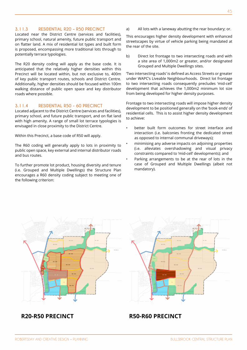
45
ROBERTSDAY AND CREATIVE DESIGN + PLANNING BULLSBROOK CENTRAL STRUCTURE PLAN
R20 - R50
R50 - R60
R20 - R50
R20 - R50
FUTURE HS
R10 - R30
R10 - R30 R5 - R20
R5 - R20
R50
R10 - R30
R20 - R50
R50
CHURCH
PS
R20 - R50
N
CADASTRAL INFORMATIONSOURCE MNG
R50 - R60 R50 - R60
FUTURE HS
R10 - R30
R10 R30R10 R30R10 - R30R10 R30 R5 R20R5 R20R5 - R20R5 - R20
R5 - R205 - R2
R10 - R30
CHURCHCHU
PSPSPSPS
R20 - R50
R50 - R60
R20 - R50
R20 - R50
FUTURE HS
R10 - R30
R10 - R30 R5 - R20
R5 - R20
R50
R10 - R30
R20 - R50
CHURCH
PS
R20 - R50
N
CADASTRAL INFORMATIONSOURCE MNG
R20 - R50R20 -
R20 - R50
R20 - R50R20 - R50
FUTURE HS
R10 - R30
R10 R30R10 R30R10 - R30R10 R30 R5 R20R5 R20R5 - R20R5 - R20
R5 - R205 - R2
R500R500
R10 - R30
50R20 - RR20 - RR20 - RR20 - RR20 RR20 RR20 RR20 R
CHURCHCHU
PSPSPSPS
R20 - R50
3.11.3 RESIDENTIAL R20 – R50 PRECINCTLocated near the District Centre (services and facilities), primary school, natural amenity, future public transport and on flatter land. A mix of residential lot types and built form is proposed, encompassing more traditional lots through to potentially terrace typologies.
The R20 density coding will apply as the base code. It is anticipated that the relatively higher densities within this Precinct will be located within, but not exclusive to, 400m of key public transport routes, schools and District Centre. Additionally, higher densities should be focused within 100m walking distance of public open space and key distributor roads where possible.
3.11.4 RESIDENTIAL R50 - 60 PRECINCTLocated adjacent to the District Centre (services and facilities), primary school, and future public transport, and on flat land with high amenity. A range of small lot terrace typologies is envisaged in close proximity to the District Centre.
Within this Precinct, a base code of R50 will apply.
The R60 coding will generally apply to lots in proximity to public open space, key external and internal distributor roads and bus routes.
To further promote lot product, housing diversity and tenure (i.e. Grouped and Multiple Dwellings) the Structure Plan encourages a R60 density coding subject to meeting one of the following criterion:
a) All lots with a laneway abutting the rear boundary; or.
This encourages higher density development with enhanced streetscapes by virtue of vehicle parking being mandated at the rear of the site.
b) Direct lot frontage to two intersecting roads and with a site area of 1,000m2 or greater, and/or designated Grouped and Multiple Dwellings sites.
‘Two intersecting roads’ is defined as Access Streets or greater under WAPC’s Liveable Neighbourhoods. Direct lot frontage to two intersecting roads consequently precludes ‘mid-cell’ development that achieves the 1,000m2 minimum lot size from being developed for higher density purposes.
Frontage to two intersecting roads will impose higher density development to be positioned generally on the ‘book-ends’ of residential cells. This is to assist higher density development to achieve:
• better built form outcomes for street interface and interaction (i.e. balconies fronting the dedicated street as opposed to internal communal driveways);
• minimising any adverse impacts on adjoining properties (i.e. alleviates overshadowing and visual privacy constraints compared to ‘mid-cell’ developments); and
• Parking arrangements to be at the rear of lots in the case of Grouped and Multiple Dwellings (albeit not mandatory).
R20-R50 PRECINCT R50-R60 PRECINCT
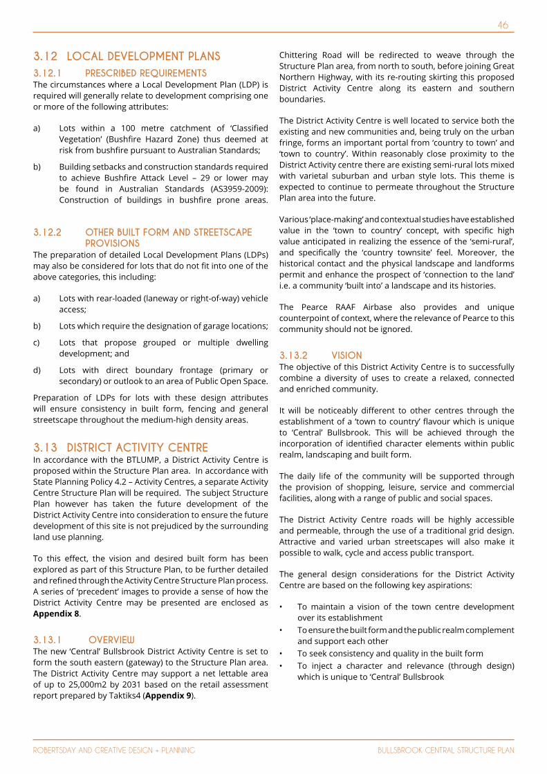
46
ROBERTSDAY AND CREATIVE DESIGN + PLANNING BULLSBROOK CENTRAL STRUCTURE PLAN
3.12 LOCAL DEVELOPMENT PLANS3.12.1 PRESCRIBED REQUIREMENTSThe circumstances where a Local Development Plan (LDP) is required will generally relate to development comprising one or more of the following attributes:
a) Lots within a 100 metre catchment of ‘Classified Vegetation’ (Bushfire Hazard Zone) thus deemed at risk from bushfire pursuant to Australian Standards;
b) Building setbacks and construction standards required to achieve Bushfire Attack Level – 29 or lower may be found in Australian Standards (AS3959-2009): Construction of buildings in bushfire prone areas.
3.12.2 OTHER BUILT FORM AND STREETSCAPE PROVISIONS
The preparation of detailed Local Development Plans (LDPs) may also be considered for lots that do not fit into one of the above categories, this including:
a) Lots with rear-loaded (laneway or right-of-way) vehicle access;
b) Lots which require the designation of garage locations;
c) Lots that propose grouped or multiple dwelling development; and
d) Lots with direct boundary frontage (primary or secondary) or outlook to an area of Public Open Space.
Preparation of LDPs for lots with these design attributes will ensure consistency in built form, fencing and general streetscape throughout the medium-high density areas.
3.13 DISTRICT ACTIVITY CENTRE In accordance with the BTLUMP, a District Activity Centre is proposed within the Structure Plan area. In accordance with State Planning Policy 4.2 – Activity Centres, a separate Activity Centre Structure Plan will be required. The subject Structure Plan however has taken the future development of the District Activity Centre into consideration to ensure the future development of this site is not prejudiced by the surrounding land use planning.
To this effect, the vision and desired built form has been explored as part of this Structure Plan, to be further detailed and refined through the Activity Centre Structure Plan process. A series of ‘precedent’ images to provide a sense of how the District Activity Centre may be presented are enclosed as Appendix 8.
3.13.1 OVERVIEWThe new ‘Central’ Bullsbrook District Activity Centre is set to form the south eastern (gateway) to the Structure Plan area. The District Activity Centre may support a net lettable area of up to 25,000m2 by 2031 based on the retail assessment report prepared by Taktiks4 (Appendix 9).
Chittering Road will be redirected to weave through the Structure Plan area, from north to south, before joining Great Northern Highway, with its re-routing skirting this proposed District Activity Centre along its eastern and southern boundaries.
The District Activity Centre is well located to service both the existing and new communities and, being truly on the urban fringe, forms an important portal from ‘country to town’ and ‘town to country’. Within reasonably close proximity to the District Activity centre there are existing semi-rural lots mixed with varietal suburban and urban style lots. This theme is expected to continue to permeate throughout the Structure Plan area into the future.
Various ‘place-making’ and contextual studies have established value in the ‘town to country’ concept, with specific high value anticipated in realizing the essence of the ‘semi-rural’, and specifically the ‘country townsite’ feel. Moreover, the historical contact and the physical landscape and landforms permit and enhance the prospect of ‘connection to the land’ i.e. a community ‘built into’ a landscape and its histories.
The Pearce RAAF Airbase also provides and unique counterpoint of context, where the relevance of Pearce to this community should not be ignored.
3.13.2 VISIONThe objective of this District Activity Centre is to successfully combine a diversity of uses to create a relaxed, connected and enriched community.
It will be noticeably different to other centres through the establishment of a ‘town to country’ flavour which is unique to ‘Central’ Bullsbrook. This will be achieved through the incorporation of identified character elements within public realm, landscaping and built form.
The daily life of the community will be supported through the provision of shopping, leisure, service and commercial facilities, along with a range of public and social spaces.
The District Activity Centre roads will be highly accessible and permeable, through the use of a traditional grid design. Attractive and varied urban streetscapes will also make it possible to walk, cycle and access public transport.
The general design considerations for the District Activity Centre are based on the following key aspirations:
• To maintain a vision of the town centre development over its establishment
• To ensure the built form and the public realm complement and support each other
• To seek consistency and quality in the built form• To inject a character and relevance (through design)
which is unique to ‘Central’ Bullsbrook

47
ROBERTSDAY AND CREATIVE DESIGN + PLANNING BULLSBROOK CENTRAL STRUCTURE PLAN
The District Activity Centre precinct, with its focus on ‘edge of town-ness’, endeavours to represent community closeness, and have elements of a relaxed (mid-sized) country town main street.
This suggests lower scale buildings around (just a few) streets of varied widths, hierarchy and character, with built form permitting some eclecticism and artistry, as if that (traditional or familiar idea of a) country town had undergone those changes from its original state, due to the attraction of the semi-rural lifestyle being rediscovered/re-invented by previously inner urban or suburban dwellers.
It should feel like this community has, over time, made it ‘their own’.
There is cause for ‘gaps’ or ‘pockets’ in streetscapes that can be ‘appropriated’ for uses that promote stopping, socialization, artistry and landscape.
The building typology can afford to be mixed, with both parapet and visible roof forms, with a scale appropriate to a wider street, but not always ‘two storey’. Shade is more important than ‘weather proofed’ and or covered outdoor spaces.
3.13.3 BUILT FORM
3.13.3.1 GUIDING PRINCIPLESWhilst there is much further work to be done, the initial thinking around the town centre built and unbuilt form will have some guiding principles that can be summarized as follows.
3.13.3.2 URBAN ELEMENTS• Legible street network with integrated, but informal,
public realm elements• Medium scale built form that imparts and country
town feel, with built form ‘civic gestures’ at appropriate locations/junctions
• Defined focal point being both a town centre and a community space
• Pedestrian focussed mainstreet, with ‘accidental gaps’, ‘breezeways’ and ‘spaces for discovery’
•
3.13.3.3 DESIGN PRINCIPLESBuilding designs that ‘represent what they are’ but remain suitable for a mix of (potentially interim) uses, with parking on‐street and within shady carparks
• Streets oriented and sized for connectivity and socialization
• High standards of built form that activate streets, ‘pocket’ spaces and ‘breezeways’
• Quality pedestrian environment on all streets with trees + shade
• Quality ‘civic gestures’ /built form terminating key vistas• Varietal but authentic ‘country town’ materiality and roof
forms
3.13.3.4 LANDSCAPE PRINCIPLES• Broad canopy street trees (including potential for some
retained mature trees) to provide suitable pedestrian and alfresco spaces
• Shaded and textured pavements to create a comfortable and interesting street environment
3.13.3.5 DESIGN INTENT Architectural quality and execution contributes to, and helps to define, the character of the public domain.
Buildings shall reflect design excellence – employing composition, proportion and balance in the design. Visual interest results from well considered use of a variety of materials and textures, and the articulation of the building form and mass. The use of textures, materials and colour should be used to articulate the facade, internal layout and reflect the structure rather than applied as decoration.
As part of the District Activity Centre, the design of the buildings shall reflect the unique location both in design response and through the appropriate choice of materials and finishes for longevity and maintenance. Additionally, the use of colour, texture and palette derived from the natural environment should inform the aesthetic response.
3.13.3.6 OBJECTIVES • To achieve design excellence that reflects and responds
to the environment and the creation of a truly unique, relaxed and ‘countrified’ town centre;
• To facilitate a cohesive streetscape with materials and finishes of a high standard;
• To develop a consistent palette of materials and colours which allow for variety and innovative architectural response;
• To provide environmentally responsive design solutions;• To offer design excellence and execution via well
considered composition, proportion, material selection and detailing, legible building entries, shopfronts and other elements;
• To respond to adjacent buildings, the streetscape design and the town centre identity when developing a design solution;
• To respond to orientation, climate and the location;• To provide built form that is a direct response to the
climate of Bullsbrook; and• To seek innovative and contemporary designs. Direct
historical reproductions and pastiche designs are not appropriate.
3.13.3.7 MATERIALS & COLOUR
3.13.3.8 DESIGN INTENTMaterial and colour selection shall respond to the inland location and the character of the town centre. This includes the use of natural materials and light and neutral colours with accents, highlights and feature colours derived from the local natural palette.
When selecting building materials, claddings and finishes, material longevity and maintenance should be considered within the local context.

48
ROBERTSDAY AND CREATIVE DESIGN + PLANNING BULLSBROOK CENTRAL STRUCTURE PLAN
3.13.3.9 OBJECTIVES• Building designs and materials should contribute
positively to the public realm• To facilitate a cohesive streetscape with materials and
finishes of a high standard• To develop a built form character specific to the
Bullsbrook town centre via a consistent palette of materials and colours which allow for variety and innovative architectural responses
• To ensure long life and ease of maintenance for the development
• To use material and colour application to articulate the building façade and overall design
3.14 MOVEMENT NETWORKS A Transport Impact Assessment, prepared by Transcore, identifies projected traffic volumes and suggested road hierarchies in and adjacent to the Structure Plan area (Appendix 7 refers). Key findings from the report include:
3.14.1 PRIMARY EXTERNAL ROAD NETWORK As a result of consultation with the MRWA, the following ‘future planned upgrades’ were identified.
• Great Northern Highway is currently part of the Perth-Darwin National Highway (PDNH) route, but a ‘Primary Regional Road’ reservation is identified on the MRS for the new Perth-Dawrin National Highway alignment further to the west.
• The section of PDNH south of Muchea is now the NorthLink WA project, with construction scheduled for completion by mid-2019. Northlink WA will be a more favourable RAV Network for some Restricted Access Vehicles, but others will remain on Great Northern Highway.
• Chittering Road will be re-aligned to enter into the Structure Plan area.
3.14.2 SITE ACCESS Access to the Structure Plan area is proposed via the following key entry points:
• A ‘left in, left out’ treatment at the intersection of the Chittering Road and the proposed Neighbourhood Connector B in the north-west of the Structure Plan.
• A roundabout treatment at the intersection of Chittering Road and Maroubra Avenue to allow full movement connection into the Structure Plan area.
• A key 4-way intersection on Great Northern Highway, near the District Activity Centre. This may either be a signalised intersection or a roundabout.
• A key 3-way intersection on Chittering Road, south of Sacri and via an existing road reserve. This is the northern access point of the Chittering Road re-alignment through the site.
• Two major access and egress points are provided within the south of the Structure Plan area, which will connect to future development sites.
• One additional major access point is provided to the north, linking with existing residential development.
• Other minor points of access and egress, to be detailed at future planning stages, will be provided within the Structure Plan area to ensure a legible road network.
3.14.3 PROPOSED INTERNAL ROAD NETWORK CONFIGURATION AND HIERARCHY
The proposed road hierarchy for the Structure Plan area is illustrated in Figure 17.
The road hierarchy focuses on the provision of two key north-south roads through the west and east of the Structure Plan area. One of the key roads is the existing Chittering Road (Integrator B) which is re-aligned to enter the Structure Plan area, whilst the other is a Neighbourhood Connector A which provides access to existing residential development in the north and future development in the south. Where lots front the Integrator B or other road over 5,000vpd, they are to be designed either so vehicles entering the street can do so travelling forward, or are provided with alternate forms of vehicle access.
Primary Distributor
Integrator B
Neighborhood Connector A
Neighborhood Connector B
Figure 17 – Road Heirachy
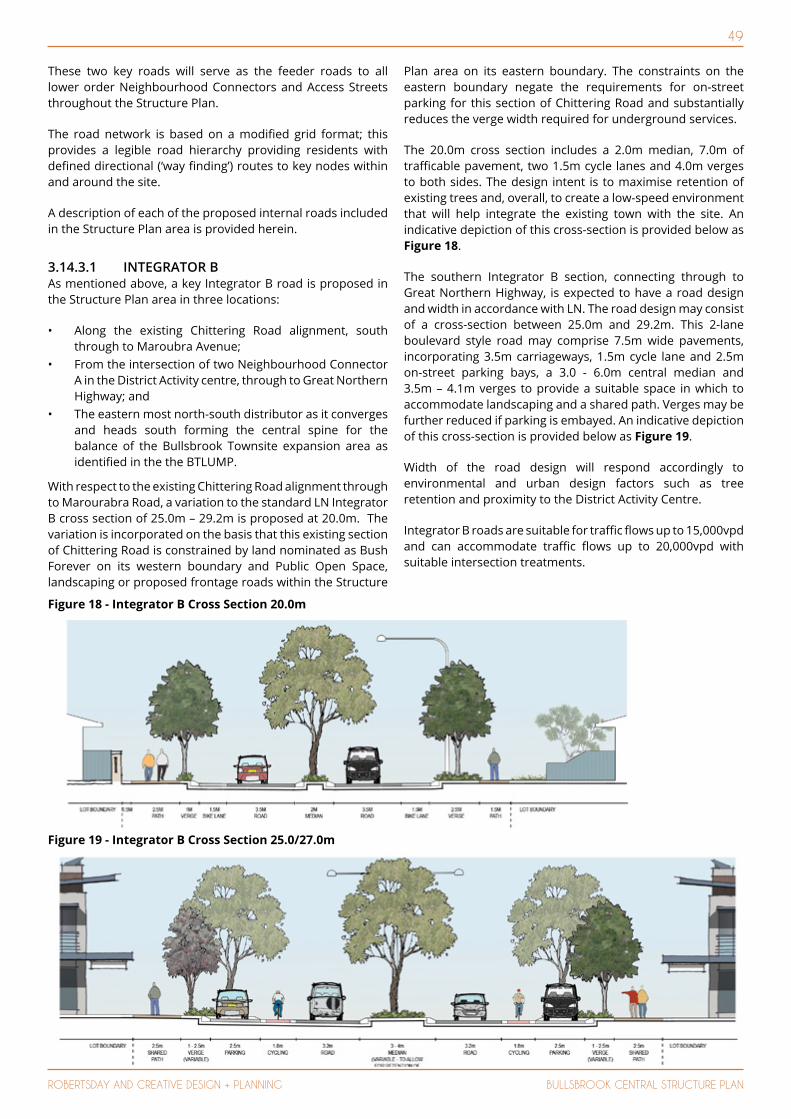
49
ROBERTSDAY AND CREATIVE DESIGN + PLANNING BULLSBROOK CENTRAL STRUCTURE PLAN
These two key roads will serve as the feeder roads to all lower order Neighbourhood Connectors and Access Streets throughout the Structure Plan.
The road network is based on a modified grid format; this provides a legible road hierarchy providing residents with defined directional (‘way finding’) routes to key nodes within and around the site.
A description of each of the proposed internal roads included in the Structure Plan area is provided herein.
3.14.3.1 INTEGRATOR BAs mentioned above, a key Integrator B road is proposed in the Structure Plan area in three locations:
• Along the existing Chittering Road alignment, south through to Maroubra Avenue;
• From the intersection of two Neighbourhood Connector A in the District Activity centre, through to Great Northern Highway; and
• The eastern most north-south distributor as it converges and heads south forming the central spine for the balance of the Bullsbrook Townsite expansion area as identified in the the BTLUMP.
With respect to the existing Chittering Road alignment through to Marourabra Road, a variation to the standard LN Integrator B cross section of 25.0m – 29.2m is proposed at 20.0m. The variation is incorporated on the basis that this existing section of Chittering Road is constrained by land nominated as Bush Forever on its western boundary and Public Open Space, landscaping or proposed frontage roads within the Structure
Plan area on its eastern boundary. The constraints on the eastern boundary negate the requirements for on-street parking for this section of Chittering Road and substantially reduces the verge width required for underground services.
The 20.0m cross section includes a 2.0m median, 7.0m of trafficable pavement, two 1.5m cycle lanes and 4.0m verges to both sides. The design intent is to maximise retention of existing trees and, overall, to create a low-speed environment that will help integrate the existing town with the site. An indicative depiction of this cross-section is provided below as Figure 18.
The southern Integrator B section, connecting through to Great Northern Highway, is expected to have a road design and width in accordance with LN. The road design may consist of a cross-section between 25.0m and 29.2m. This 2-lane boulevard style road may comprise 7.5m wide pavements, incorporating 3.5m carriageways, 1.5m cycle lane and 2.5m on-street parking bays, a 3.0 - 6.0m central median and 3.5m – 4.1m verges to provide a suitable space in which to accommodate landscaping and a shared path. Verges may be further reduced if parking is embayed. An indicative depiction of this cross-section is provided below as Figure 19.
Width of the road design will respond accordingly to environmental and urban design factors such as tree retention and proximity to the District Activity Centre.
Integrator B roads are suitable for traffic flows up to 15,000vpd and can accommodate traffic flows up to 20,000vpd with suitable intersection treatments.
Figure 18 - Integrator B Cross Section 20.0m
Figure 19 - Integrator B Cross Section 25.0/27.0m
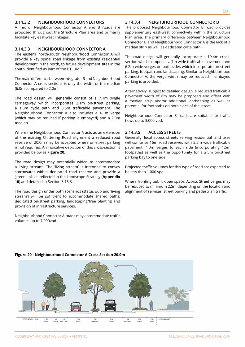
50
ROBERTSDAY AND CREATIVE DESIGN + PLANNING BULLSBROOK CENTRAL STRUCTURE PLAN
3.14.3.2 NEIGHBOURHOOD CONNECTORS A mix of Neighbourhood Connector A and B roads are proposed throughout the Structure Plan area and primarily facilitate key east-west linkages.
3.14.3.3 NEIGHBOURHOOD CONNECTOR AThe eastern ‘north-south’ Neighbourhood Connector A will provide a key spinal road linkage from existing residential development in the north, to future development sites in the south identified as part of the BTLUMP
The main difference between Integrator B and Neighbourhood Connector A cross-sections is only the width of the median (6.0m compared to 2.0m).
The road design will generally consist of a 7.1m single carriageway which incorporates 2.1m on-street parking, a 1.5m cycle path and 3.5m trafficable pavement. The Neighbourhood Connector A also includes a 4.1m verge (which may be reduced if parking is embayed) and a 2.0m median.
Where the Neighbourhood Connector A acts as an extension of the existing Chittering Road alignment a reduced road reserve of 20.0m may be accepted where on-street parking is not required. An indicative depiction of this cross-section is provided below as Figure 20.
The road design may potentially widen to accommodate a ‘living stream’. The ‘living stream’ is intended to convey stormwater within dedicated road reserve and provide a ‘green-link’ as reflected in the Landscape Strategy (Appendix 10) and detailed in Section 3.15.3.
The road design under both scenarios (status quo and ‘living stream’) will be sufficient to accommodate shared paths, dedicated on-street parking, landscaping/tree planting and provision of infrastructure services.
Neighbourhood Connector A roads may accommodate traffic volumes up to 7,000vpd.
3.14.3.4 NEIGHBHOURHOOD CONNECTOR BThe proposed Neighbourhood Connector B road provides supplementary east-west connectivity within the Structure Plan area. The primary difference between Neighbourhood Connector B and Neighbourhood Connector A is the lack of a median strip as well as dedicated cycle path.
The road design will generally incorporate a 19.4m cross-section which comprises a 7m wide trafficable pavement and 6.2m wide verges on both sides which incorporate on-street parking, footpath and landscaping. Similar to Neighbourhood Connector A, the verge width may be reduced if embayed parking is provided.
Alternatively, subject to detailed design, a reduced trafficable pavement width of 6m may be proposed and offset with a median strip and/or additional landscaping as well as potential for footpaths on both sides of the street.
Neighbourhood Connector B roads are suitable for traffic flows up to 3,000 vpd.
3.14.3.5 ACCESS STREETS Generally, local access streets serving residential land uses will comprise 16m road reserves with 5.5m wide trafficable pavement, 4.0m verges to each side (incorporating 1.5m footpaths) as well as the opportunity for a 2.5m on-street parking bay to one side.
Projected traffic volumes for this type of road are expected to be less than 1,000 vpd.
Where fronting public open space, Access Street verges may be reduced to minimum 2.5m depending on the location and alignment of services, street parking and pedestrian traffic.
Figure 20 - Neighbourhood Connector A Cross Section 20.0m
51
ROBERTSDAY AND CREATIVE DESIGN + PLANNING BULLSBROOK CENTRAL STRUCTURE PLAN
3.14.4 PUBLIC TRANSPORTThe Structure Plan area currently has access to the 311 bus service which runs on Great Northern Highway adjacent to the Structure Plan area. The 311 provides six bus services each way on weekdays and two on Saturdays, Sundays and public holidays. It is also notated that the BTLUMP envisages a bus depot within the DAC or surrounds.
The Structure Plan design allows for bus services on all of the proposed Neighbourhood Connector and Integrator B roads, which are a suitable standard to accommodate bus services. This allows flexibility for the Public Transport Authority to plan future bus routes within this area.
3.14.5 PEDESTRIAN AND CYCLE INFRASTRUCTURE
In accordance with the requirements of Liveable Neighbourhoods, paths are to be provided to both sides of all Integrator B and Neighbourhood Connector roads, with at least one side being a shared path.
All Access Streets are to have a shared path or footpath on at least one side of the carriageway subject to local demand.
3.14.6 INTEGRATION WITH THE SURROUNDING AREA
The BTLUMP provides an overall plan to ensure coordination of future development of the Structure Plan area, adjoining landholding and wider Bullsbrook townsite. The proposed Structure Plan respects and reflects the principles and external connections of the BTLUMP to ensure that good connectivity and integration with the surrounding area are achieved.
3.15 PUBLIC OPEN SPACE A POS Schedule has been prepared for the Structure Plan area (Table 4 refers) and illustrates compliance with the 10% creditable POS requirement in accordance with Liveable Neighbourhoods guidance, the WAPC’s Development Control (DC) Policy 2.3 Public Open Space in Residential Areas and the City of Swan’s Local Planning Policy POL-C-112 Public Open Space – Residential Areas. The location of each area of POS is identified on Figure 21.
A Landscape Strategy (Appendix 10), including a Landscape Master Plan has been prepared by Emerge Associates in support of the Structure Plan (Figures 23 – 27 refer).
These plans collectively rationalise the land areas, POS hierarchy, required drainage provision and suggested landscape form and intended long term development.
The POS areas are distributed and will be designed so as to create a ‘green-link’ throughout the Structure Plan area, facilitated through local ‘precinct’ amenity and ‘green streets’.
The POS Schedule will be continually reviewed under the more detailed subdivision and engineering design stages, as drainage provision, earthworks and nett residential development cells are further adjusted.
The areas of POS within the Structure Plan area have been separated into broad categories based on their specific treatments and design. The Structure Plan proposes a total of 20 areas of creditable Public Open Space (POS), in addition to a District Open Space and the Ki-It Monger Brook core creek area.
3.15.1 LOCAL AMENITYThe positioning and configuration of POS areas is influenced by the desire to provide a continuous east-west ‘green-link’ through the Structure Plan area; this to enhance and improve pedestrian connectivity and synergy between key POS areas.
The ‘green-link’ and ‘linear’ POS layout will enable a safe, attractive and appealing pedestrian link (focus) across the entire Structure Plan area. Also of importance is the role it will play in providing a drainage function.
A total of 19 ‘neighbourhood’ POS areas and one ‘local’ POS area is proposed throughout the Structure Plan area. These typically larger (i.e. 2700m2 – 12,000m2) areas of POS will generally be informal in nature and characterised by revegetation and native parkland plantings to encourage passive recreation uses. Additionally, they will provide local residents with areas of localised turf for informal active recreation.
POS 18 is significantly larger than the other ‘neighbourhood’ POS providing approximately 4.42ha of creditable open space. The purpose of this POS is primarily to provide for the retention of trees in an area nominated as a ‘specific commitment area’ under the Draft Green Growth Plan. Although POS 18 provides for a specific retention function, it remains accessible and will provide for both active and passive recreation.
Linkages with adjoining residential streets and the linear POS network (detailed further in Section 3.15.2 below) will provide the necessary access to these significant areas of POS. The POS areas will form an interconnected series of spaces along the linear park network, each with the potential to offer rest areas for elderly or disabled residents, or exercise stations for others.
Drainage areas may be required within these areas of POS. Where drainage is required landscaped basins will be provided to serve a recreational and amenity function. Drainage swales catering for events greater than a 1:5 event will have turf to enable multiple use and ease of maintenance.
Within each POS, the extent of hardscape and ‘urbanity’ of the space will increase in proximity to the District Activity Centre.
The POS are proposed to create areas of local amenity within 400m of most dwellings, servicing approximately 600 dwellings within the surrounding area.

52
ROBERTSDAY AND CREATIVE DESIGN + PLANNING BULLSBROOK CENTRAL STRUCTURE PLAN
CHITTERING ROAD
NO
CURN
E RI
SE
CANTATA AVENUE
PARK
LAN
D P
ARA
DE
CHITTERING ROAD
CAPO
RN S
TREE
T
BREA
RLEY
ST
REET
FUTU
RE H
S
CHU
RCH
HO
MES
TEA
D
TOW
NCE
NTR
E
TOW
NCE
NTR
E
TOW
NCE
NTR
E
PLA
YIN
GFI
ELD
PRIM
ARY
SCH
OO
L
PLA
YIN
GFI
ELD
CHITTERING ROAD
GREAT NORTHERN HIGHWAY
GREAT NORTHERN HIGHWAY
CAPO
RN S
TREE
TKING STREET
BULL
SBRO
OK
RO
AD
FRIG
ATE
W
AY
PARK
LAN
D
PARA
DE
MAR
OU
BRA
AVE
BOW
MA
N
STR
EET
BRIG
W
AY
CANTATA AVE
LOW
ERY
PARK
BULL
SBRO
OK
CO
LLEG
EBU
LLSB
ROO
K C
OLL
EGE
TOW
N C
ENTR
E /
ROU
ND
ABO
UT
TOCO
NN
ECT
GRE
AT
NO
RTH
ERN
HIG
HW
AY
BUSH
FO
REVE
R
BREA
RLEY
ST
REET
MCKAY PL
EDEN
D
RIVE
LANE
AD
AG
IO
WA
Y
NO
CTU
RN
RISE
EMER
ALD
BAN
KSIA
CT
RETR
EAT
GOLD
EN
BALL
AD
CRE
S
WAY
FIELD
CHITTERING ROAD
BALL
AD
PARK
ETH
EL W
ARR
ENBU
LLSB
ROO
KCO
MM
UN
ITY
CEN
TRE
PICK
ETT
PARK
18
12
16
135
4
3
2
15
10
11
14
1A3
8
6
9
17
7
1B
19
SACR
I13
.36h
a
LEG
END
1000 metres
200
300
400
N
500
DIS
CLA
IMER
: ISS
UED
FO
R D
ESIG
N IN
TEN
T O
NLY
. ALL
ARE
AS
AN
D D
IMEN
SIO
NS
ARE
SU
BJEC
T TO
DET
AIL
DES
IGN
AN
D S
URV
EY
PUBL
IC O
PEN
SPA
CEBu
llsbroo
kCi
ty o
f Sw
an
SIZE
A4
S
CALE
1:10
,000
RD1 1
09D
RAW
NO
.B
AMX
BUL
REF
NO
.RE
V.
10
SUBJ
ECT
LAN
D
EXIS
TIN
G L
OT
BOU
ND
ARY
URB
AN
RECR
EATI
ON
RECR
EATI
ON
(CO
RE C
REEK
ARE
A)
RECR
EATI
ON
(PLA
YIN
G F
IELD
)
WA
TERB
OD
Y
RECR
EATI
ON
(REF
EREN
CE N
O.)
Figure 21 - Public Open Space
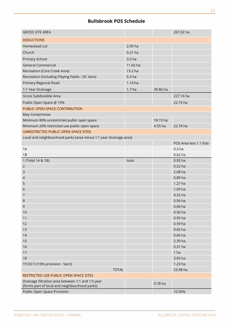
53
ROBERTSDAY AND CREATIVE DESIGN + PLANNING BULLSBROOK CENTRAL STRUCTURE PLAN
Bullsbrook POS Schedule
GROSS SITE AREA 267.02 ha
DEDUCTIONS
Homestead Lot 2.09 ha
Church 0.21 ha
Primary School 3.5 ha
General Commercial 11.65 ha
Recreation (Core Creek Area) 13.2 ha
Recreation (Including Playing Fields - DC item) 6.3 ha
Primary Regional Road 1.14 ha
1:1 Year Drainage 1.7 ha 39.86 ha
Gross Subdivisible Area 227.16 ha
Public Open Space @ 10% 22.74 ha
PUBLIC OPEN SPACE CONTRIBUTION
May Comprimise:
Minimum 80% unrestricted public open space 18.19 ha
Minimum 20% restricted use public open space 4.55 ha 22.74 ha
UNRESTRICTED PUBLIC OPEN SPACE SITES
Local and neighbourhood parks (area minus 1:1 year drainage area)
POS Area less 1.1 (ha)
1A 0.3 ha
1B 0.62 ha
1 (Total 1A & 1B) total 0.92 ha
2 0.22 ha
3 2.08 ha
4 0.89 ha
5 1.27 ha
6 1.09 ha
7 4.32 ha
8 0.56 ha
9 0.66 ha
10 0.36 ha
11 0.95 ha
12 0.59 ha
13 0.65 ha
14 0.66 ha
15 2.39 ha
16 0.31 ha
17 1 ha
18 3.83 ha
19 (SC1) (10% provision - Sacri) 1.23 ha
TOTAL 23.98 ha
RESTRICTED USE PUBLIC OPEN SPACE SITES
Drainage filtration area between 1:1 and 1:5 year (forms part of local and neighbourhood parks)
0.78 ha
Public Open Space Provision 10.56%
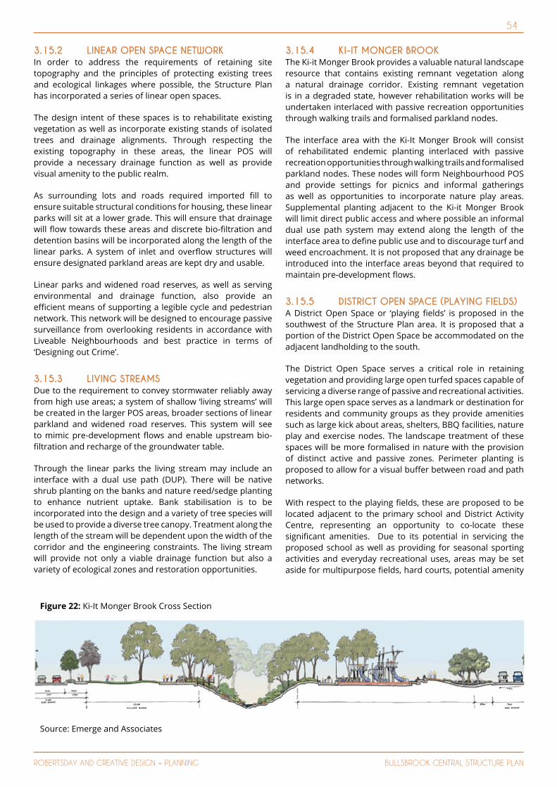
54
ROBERTSDAY AND CREATIVE DESIGN + PLANNING BULLSBROOK CENTRAL STRUCTURE PLAN
3.15.2 LINEAR OPEN SPACE NETWORK In order to address the requirements of retaining site topography and the principles of protecting existing trees and ecological linkages where possible, the Structure Plan has incorporated a series of linear open spaces.
The design intent of these spaces is to rehabilitate existing vegetation as well as incorporate existing stands of isolated trees and drainage alignments. Through respecting the existing topography in these areas, the linear POS will provide a necessary drainage function as well as provide visual amenity to the public realm.
As surrounding lots and roads required imported fill to ensure suitable structural conditions for housing, these linear parks will sit at a lower grade. This will ensure that drainage will flow towards these areas and discrete bio-filtration and detention basins will be incorporated along the length of the linear parks. A system of inlet and overflow structures will ensure designated parkland areas are kept dry and usable.
Linear parks and widened road reserves, as well as serving environmental and drainage function, also provide an efficient means of supporting a legible cycle and pedestrian network. This network will be designed to encourage passive surveillance from overlooking residents in accordance with Liveable Neighbourhoods and best practice in terms of ‘Designing out Crime’.
3.15.3 LIVING STREAMSDue to the requirement to convey stormwater reliably away from high use areas; a system of shallow ‘living streams’ will be created in the larger POS areas, broader sections of linear parkland and widened road reserves. This system will see to mimic pre-development flows and enable upstream bio-filtration and recharge of the groundwater table.
Through the linear parks the living stream may include an interface with a dual use path (DUP). There will be native shrub planting on the banks and nature reed/sedge planting to enhance nutrient uptake. Bank stabilisation is to be incorporated into the design and a variety of tree species will be used to provide a diverse tree canopy. Treatment along the length of the stream will be dependent upon the width of the corridor and the engineering constraints. The living stream will provide not only a viable drainage function but also a variety of ecological zones and restoration opportunities.
3.15.4 KI-IT MONGER BROOK The Ki-it Monger Brook provides a valuable natural landscape resource that contains existing remnant vegetation along a natural drainage corridor. Existing remnant vegetation is in a degraded state, however rehabilitation works will be undertaken interlaced with passive recreation opportunities through walking trails and formalised parkland nodes.
The interface area with the Ki-It Monger Brook will consist of rehabilitated endemic planting interlaced with passive recreation opportunities through walking trails and formalised parkland nodes. These nodes will form Neighbourhood POS and provide settings for picnics and informal gatherings as well as opportunities to incorporate nature play areas. Supplemental planting adjacent to the Ki-it Monger Brook will limit direct public access and where possible an informal dual use path system may extend along the length of the interface area to define public use and to discourage turf and weed encroachment. It is not proposed that any drainage be introduced into the interface areas beyond that required to maintain pre-development flows.
3.15.5 DISTRICT OPEN SPACE (PLAYING FIELDS)A District Open Space or ‘playing fields’ is proposed in the southwest of the Structure Plan area. It is proposed that a portion of the District Open Space be accommodated on the adjacent landholding to the south.
The District Open Space serves a critical role in retaining vegetation and providing large open turfed spaces capable of servicing a diverse range of passive and recreational activities. This large open space serves as a landmark or destination for residents and community groups as they provide amenities such as large kick about areas, shelters, BBQ facilities, nature play and exercise nodes. The landscape treatment of these spaces will be more formalised in nature with the provision of distinct active and passive zones. Perimeter planting is proposed to allow for a visual buffer between road and path networks.
With respect to the playing fields, these are proposed to be located adjacent to the primary school and District Activity Centre, representing an opportunity to co-locate these significant amenities. Due to its potential in servicing the proposed school as well as providing for seasonal sporting activities and everyday recreational uses, areas may be set aside for multipurpose fields, hard courts, potential amenity
Source: Emerge and Associates
Figure 22: Ki-It Monger Brook Cross Section
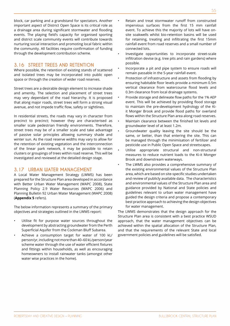
55
ROBERTSDAY AND CREATIVE DESIGN + PLANNING BULLSBROOK CENTRAL STRUCTURE PLAN
block, car parking and a grandstand for spectators. Another important aspect of District Open Space is its critical role as a drainage area during significant stormwater and flooding events. The playing field’s capacity for organised sporting and district scale community events will contribute towards nurturing social interaction and promoting local fabric within the community. All facilities require confirmation of funding through the development contribution scheme.
3.16 STREET TREES AND RETENTION Where possible, the retention of existing stands of scattered and isolated trees may be incorporated into public open space or through the creation of wider road reserves.
Street trees are a desirable design element to increase shade and amenity. The selection and placement of street trees may very dependant of the road hierarchy. It is proposed that along major roads, street trees will form a strong visual avenue, and not impede traffic flow, safety or sightlines.
In residential streets, the roads may vary in character from precinct to precinct; however they are characterised as smaller scale pedestrian friendly environments. Therefore, street trees may be of a smaller scale and take advantage of passive solar principles allowing summary shade and winter sun. As the road reserve widths may vary to allow for the retention of existing vegetation and the interconnection of the linear park network, it may be possible to retain clusters or groupings of trees within road reserve. This will be investigated and reviewed at the detailed design stage.
3.17 URBAN WATER MANAGEMENT A Local Water Management Strategy (LWMS) has been prepared for the Structure Plan area developed in accordance with Better Urban Water Management (WAPC 2008), State Planning Policy 2.9 Water Resources (WAPC 2006) and Planning Bulletin 92 Urban Water Management (WAPC 2008) (Appendix 5 refers).
The below information represents a summary of the primary objectives and strategies outlined in the LWMS report:
• Utilise fit for purpose water sources throughout the development by abstracting groundwater from the Perth Superficial Aquifer from the Cockman Bluff Subarea.
• Achieve a consumption target for water of 100 kL/person/yr, including not more than 40–60 kL/person/year scheme water through the use of water efficient fixtures and fittings within households, as well as encouraging homeowners to install rainwater tanks (amongst other water wise practices in the home).
• Retain and treat stormwater runoff from constructed impervious surfaces from the first 15 mm rainfall event. To achieve this the majority of lots will have on-site soakwells whilst bio-retention basins will be used for retaining, treating and infiltrating the first 15mm rainfall event from road reserves and a small number of connected lots.
• Investigate opportunities to incorporate street-scale infiltration devise (e.g. tree pits and rain gardens) where possible.
• Incorporate a pit and pipe system to ensure roads will remain passable in the 5-year rainfall event.
• Protection of infrastructure and assets from flooding by ensuring habitable floor levels provide a minimum 0.5m vertical clearance from watercourse flood levels and 0.3m clearance from local drainage systems.
• Provide storage and delineate flow paths for the 1% AEP event. This will be achieved by providing flood storage to maintain the pre-development hydrology of the Ki-it Monger Brook and provide flood paths for overland flows within the Structure Plan area along road reserves.
• Maintain clearance between the finished lot levels and groundwater level of at least 1.2m.
• Groundwater quality leaving the site should be the same, or better, than that entering the site. This can be managed through the minimisation of fertilizer and pesticide use in Public Open Space and streetscapes.
• Utilise appropriate structural and non-structural measures to reduce nutrient loads to the Ki-it Monger Brook and downstream waterways.
• The LWMS also provides a comprehensive summary of the existing environmental values of the Structure Plan area, which are based on site-specific studies undertaken and review of publicly available data. The characteristics and environmental values of the Structure Plan area and guidance provided by National and State policies and guidelines relevant to urban water management have guided the design criteria and propose a contemporary best practice approach to achieving the design objectives for water management.
The LWMS demonstrates that the design approach for the Structure Plan area is consistent with a best practice WSUD approach, that the water management objectives can be achieved within the spatial allocation of the Structure Plan, and that the requirements of the relevant State and local government policies and guidelines will be satisfied.
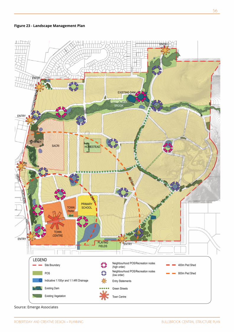
56
ROBERTSDAY AND CREATIVE DESIGN + PLANNING BULLSBROOK CENTRAL STRUCTURE PLAN
EMERGE 22
400m
800m
PLAYING FIELDS
TOWN CENTRE
SACRICHURCH
HOMESTEAD
PRIMARY SCHOOL
KI-IT MONGER BROOK
CHIT
TERI
NG R
OAD
4. APPENDIX A LANDSCAPE MASTERPLAN
EXISTING DAM
TOWN PARK
ENTRY
ENTRY
ENTRY
ENTRYENTRY
GREATNORTHERN
HWY
LEGEND
POS
Indicative 1:100yr and 1:1 ARI Drainage
Neighbourhood POS/Recreation nodes (high order)Site Boundary
Existing Vegetation Town Centre
Existing Dam
Entry Statements
400m Ped Shed
800m Ped ShedNeighbourhood POS/Recreation nodes (low order)
Green Streets
Source: Emerge Associates
Figure 23 - Landscape Management Plan
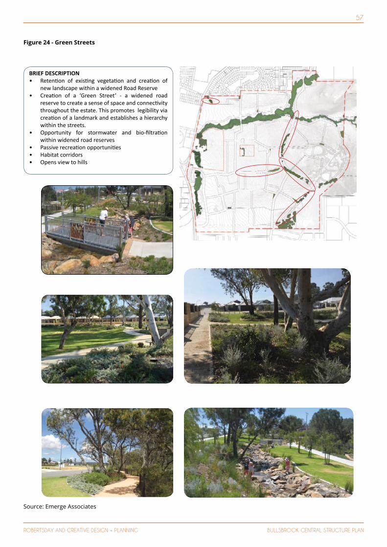
57
ROBERTSDAY AND CREATIVE DESIGN + PLANNING BULLSBROOK CENTRAL STRUCTURE PLAN
Source: Emerge Associates
Figure 24 - Green Streets
EMERGE 25
7. POS STRATEGY GREEN STREETS
BRIEF DESCRIPTION • Reten on of exis ng vegeta on and crea on of
new landscape within a widened Road Reserve• Crea on of a ‘Green Street’ - a widened road
reserve to create a sense of space and connec vity throughout the estate. This promotes legibility via crea on of a landmark and establishes a hierarchy within the streets.
• Opportunity for stormwater and bio- ltra on within widened road reserves
• Passive recrea on opportuni es• Habitat corridors• Opens view to hills

58
ROBERTSDAY AND CREATIVE DESIGN + PLANNING BULLSBROOK CENTRAL STRUCTURE PLAN
EMERGE 26
FUNCTIONS• Na ve, water wise plan ng. Deciduous used when
and where appropriate • Maximise shade trees with emphasis on na ve
species• Limited picnic facili es• Internal path network• Path network connec ng into the broader path
network• Drainage• Passive solar• Historical and cultural character• Landmark and feature plan ng
ENVIRONMENTAL CONSIDERATIONS• Waterwise na ve plan ng• Plan ng design to be zoned according to irriga on
requirement, with full irriga on requirements to the informal turf playing area
• Source local materials where possible• Consider the long term maintenance requirements
for all materials
BRIEF DESCRIPTION Located throughout the development, the Neighbourhood POS provides residents with open space in close proximity to their dwellings. The parks have areas of turf for passive play and informal kick about area with nodes of sea ng and shelter either provided by trees or built structure. A path network through and around the POS allows footpath connec on to surrounding streets and other POS. Drainage will be incorporated within these areas.
SIZE (Excluding Verges)POS 1: 3,111 sq.m POS 7: 4,951 sq.mPOS 2: 2,730 sq.m POS 8: 7,065 sq.mPOS 3: 6,192 sq.m POS 9: 7,502 sq.mPOS 4: 3,080 sq.m POS 10: 4,358 sq.mPOS 5: 3,348 sq.m POS 11: 7,032 sq.mPOS 6: 11,073 sq.m POS 12: 1,399 sq.m
8. POS STRATEGY NEIGHBOURHOOD PARKS
TOWN PARK
1
2 3
4
56
7
8 9
1011
12
Source: Emerge Associates
Figure 25 - Neighbourhood Parks
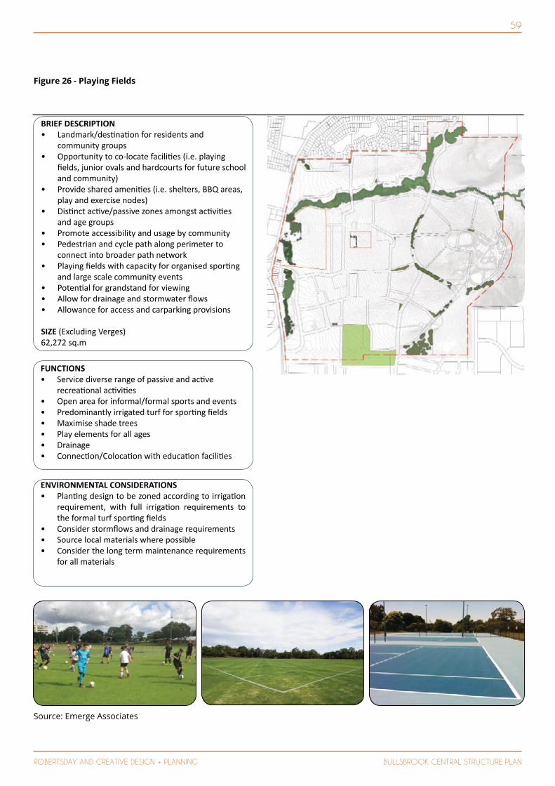
59
ROBERTSDAY AND CREATIVE DESIGN + PLANNING BULLSBROOK CENTRAL STRUCTURE PLAN
Source: Emerge Associates
Figure 26 - Playing Fields
EMERGE 27
FUNCTIONS• Service diverse range of passive and ac ve
recrea onal ac vi es • Open area for informal/formal sports and events• Predominantly irrigated turf for spor ng elds• Maximise shade trees• Play elements for all ages• Drainage• Connec on/Coloca on with educa on facili es
ENVIRONMENTAL CONSIDERATIONS• Plan ng design to be zoned according to irriga on
requirement, with full irriga on requirements to the formal turf spor ng elds
• Consider storm ows and drainage requirements• Source local materials where possible• Consider the long term maintenance requirements
for all materials
BRIEF DESCRIPTION • Landmark/des na on for residents and
community groups• Opportunity to co-locate facili es (i.e. playing
elds, junior ovals and hardcourts for future school and community)
• Provide shared ameni es (i.e. shelters, BBQ areas, play and exercise nodes)
• Dis nct ac ve/passive zones amongst ac vi es and age groups
• Promote accessibility and usage by community• Pedestrian and cycle path along perimeter to
connect into broader path network• Playing elds with capacity for organised spor ng
and large scale community events• Poten al for grandstand for viewing• Allow for drainage and stormwater ows• Allowance for access and carparking provisions
SIZE (Excluding Verges)62,272 sq.m
9. POS STRATEGY DISTRICT POS/PLAYING FIELDS
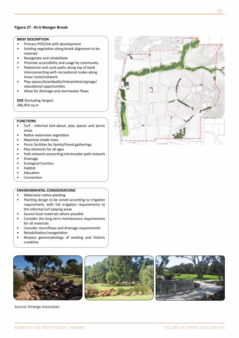
60
ROBERTSDAY AND CREATIVE DESIGN + PLANNING BULLSBROOK CENTRAL STRUCTURE PLANEMERGE 29
FUNCTIONS• Turf - informal kick-about, play spaces and picnic
areas• Na ve waterwise vegeta on• Maximise shade trees• Picnic facili es for family/friend gatherings• Play elements for all ages• Path network connec ng into broader path network• Drainage• Ecological func on• Habitat• Educa on• Connec on
ENVIRONMENTAL CONSIDERATIONS• Waterwise na ve plan ng• Plan ng design to be zoned according to irriga on
requirement, with full irriga on requirements to the informal turf playing areas
• Source local materials where possible• Consider the long term maintenance requirements
for all materials• Consider storm ows and drainage requirements• Rehabilita on/revegeta on• Respect geomorphology of exis ng and historic
creekline
BRIEF DESCRIPTION • Primary POS/link with development• Exis ng vegeta on along brook alignment to be
retained• Revegetate and rehabilitate• Promote accessibility and usage by community• Pedestrian and cycle paths along top of bank
interconnec ng with recrea onal nodes along linear route/network.
• Play spaces/boardwalks/interpre ve/signage/educa onal opportuni es
• Allow for drainage and stormwater ows
SIZE (Excluding Verges)286,954 sq.m
11. POS STRATEGY KI IT MONGER BROOK
Source: Emerge Associates
Figure 27 - Ki-it Monger Brook
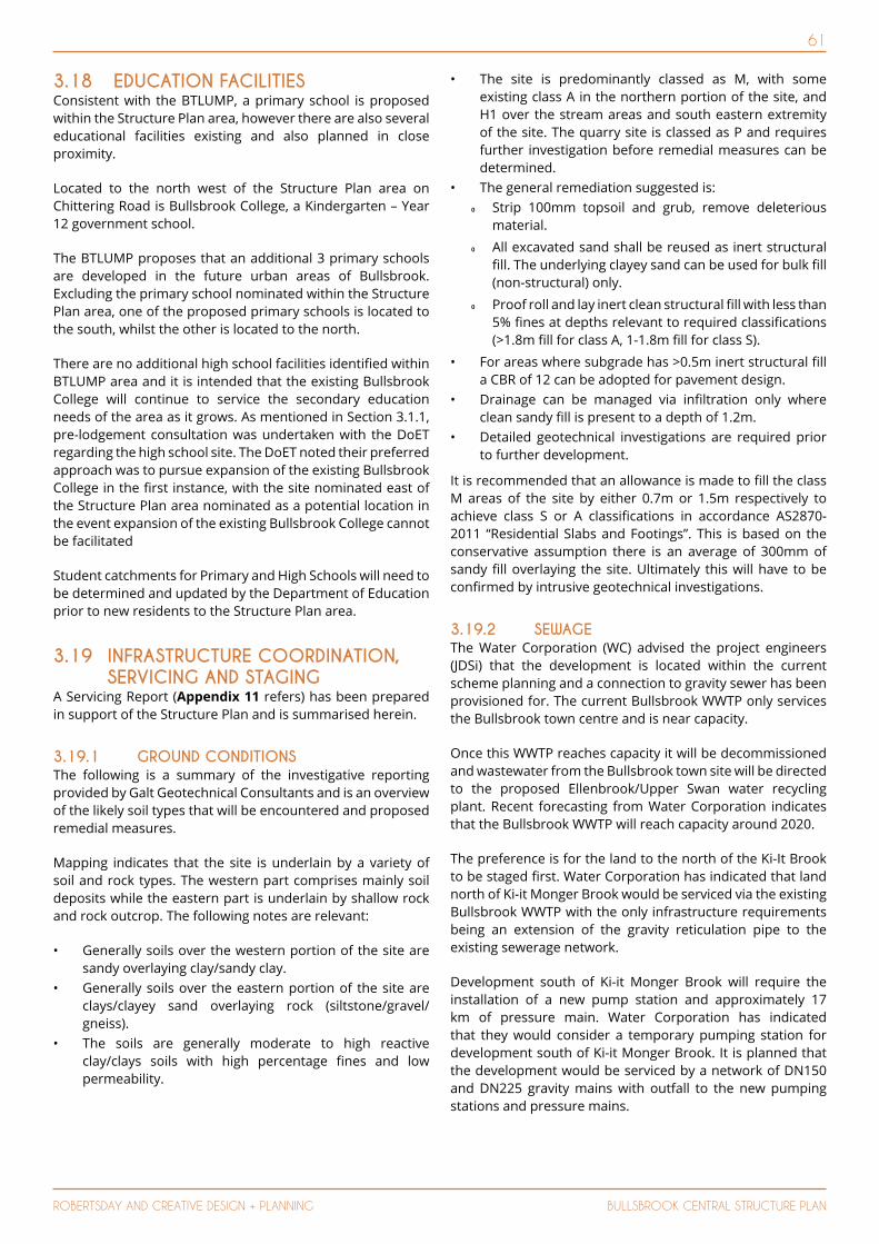
61
ROBERTSDAY AND CREATIVE DESIGN + PLANNING BULLSBROOK CENTRAL STRUCTURE PLAN
3.18 EDUCATION FACILITIESConsistent with the BTLUMP, a primary school is proposed within the Structure Plan area, however there are also several educational facilities existing and also planned in close proximity.
Located to the north west of the Structure Plan area on Chittering Road is Bullsbrook College, a Kindergarten – Year 12 government school.
The BTLUMP proposes that an additional 3 primary schools are developed in the future urban areas of Bullsbrook. Excluding the primary school nominated within the Structure Plan area, one of the proposed primary schools is located to the south, whilst the other is located to the north.
There are no additional high school facilities identified within BTLUMP area and it is intended that the existing Bullsbrook College will continue to service the secondary education needs of the area as it grows. As mentioned in Section 3.1.1, pre-lodgement consultation was undertaken with the DoET regarding the high school site. The DoET noted their preferred approach was to pursue expansion of the existing Bullsbrook College in the first instance, with the site nominated east of the Structure Plan area nominated as a potential location in the event expansion of the existing Bullsbrook College cannot be facilitated
Student catchments for Primary and High Schools will need to be determined and updated by the Department of Education prior to new residents to the Structure Plan area.
3.19 INFRASTRUCTURE COORDINATION, SERVICING AND STAGING
A Servicing Report (Appendix 11 refers) has been prepared in support of the Structure Plan and is summarised herein.
3.19.1 GROUND CONDITIONSThe following is a summary of the investigative reporting provided by Galt Geotechnical Consultants and is an overview of the likely soil types that will be encountered and proposed remedial measures.
Mapping indicates that the site is underlain by a variety of soil and rock types. The western part comprises mainly soil deposits while the eastern part is underlain by shallow rock and rock outcrop. The following notes are relevant:
• Generally soils over the western portion of the site are sandy overlaying clay/sandy clay.
• Generally soils over the eastern portion of the site are clays/clayey sand overlaying rock (siltstone/gravel/gneiss).
• The soils are generally moderate to high reactive clay/clays soils with high percentage fines and low permeability.
• The site is predominantly classed as M, with some existing class A in the northern portion of the site, and H1 over the stream areas and south eastern extremity of the site. The quarry site is classed as P and requires further investigation before remedial measures can be determined.
• The general remediation suggested is: Κ Strip 100mm topsoil and grub, remove deleterious
material. Κ All excavated sand shall be reused as inert structural
fill. The underlying clayey sand can be used for bulk fill (non-structural) only.
Κ Proof roll and lay inert clean structural fill with less than 5% fines at depths relevant to required classifications (>1.8m fill for class A, 1-1.8m fill for class S).
• For areas where subgrade has >0.5m inert structural fill a CBR of 12 can be adopted for pavement design.
• Drainage can be managed via infiltration only where clean sandy fill is present to a depth of 1.2m.
• Detailed geotechnical investigations are required prior to further development.
It is recommended that an allowance is made to fill the class M areas of the site by either 0.7m or 1.5m respectively to achieve class S or A classifications in accordance AS2870-2011 “Residential Slabs and Footings”. This is based on the conservative assumption there is an average of 300mm of sandy fill overlaying the site. Ultimately this will have to be confirmed by intrusive geotechnical investigations.
3.19.2 SEWAGE The Water Corporation (WC) advised the project engineers (JDSi) that the development is located within the current scheme planning and a connection to gravity sewer has been provisioned for. The current Bullsbrook WWTP only services the Bullsbrook town centre and is near capacity.
Once this WWTP reaches capacity it will be decommissioned and wastewater from the Bullsbrook town site will be directed to the proposed Ellenbrook/Upper Swan water recycling plant. Recent forecasting from Water Corporation indicates that the Bullsbrook WWTP will reach capacity around 2020.
The preference is for the land to the north of the Ki-It Brook to be staged first. Water Corporation has indicated that land north of Ki-it Monger Brook would be serviced via the existing Bullsbrook WWTP with the only infrastructure requirements being an extension of the gravity reticulation pipe to the existing sewerage network.
Development south of Ki-it Monger Brook will require the installation of a new pump station and approximately 17 km of pressure main. Water Corporation has indicated that they would consider a temporary pumping station for development south of Ki-it Monger Brook. It is planned that the development would be serviced by a network of DN150 and DN225 gravity mains with outfall to the new pumping stations and pressure mains.

62
ROBERTSDAY AND CREATIVE DESIGN + PLANNING BULLSBROOK CENTRAL STRUCTURE PLAN
3.19.3 WATER SUPPLY The Water Corporation (WC) has advised that the Structure Plan area is located within the current scheme planning and a connection to water reticulation has been provisioned for under an upgrade of the existing infrastructure located within Great Northern Highway (GNH).
The WC had completed the planning study for the delivery of additional water services to the Bullsbrook area. This included supply to the residential area on the eastern side of Great Northern Highway and Chittering Road including the proposed development site. WC advised that supply to the Structure Plan area would be via a new DN200 distribution main between Hurd Road and Parkland Parade installed to the west of the site along Chittering Road.
3.19.4 POWER SUPPLY Although Western Power Network Capacity Mapping Tool indicates that there is enough capacity to feed the estimated ultimate 2500+ lots, due to the capacity limitation of the existing 22kV high voltage aerial feeder and the dynamics of the power network, a Western Power feasibility study to further investigate the existing network capacity.
Notwithstanding the above, it is estimated that the first 500 dwellings within the Structure Plan area can be serviced by existing surrounding infrastructure cable. Additional infrastructure may be required to provide the necessary power to the remainder of the site.
3.19.5 TELECOMMUNICATIONS NBN will be the primary telecommunication service provider for the Structure Plan area. NBN Co has advised that the development can be serviced from their existing infrastructure in the vicinity of the site.
After NBN connectivity for the development has been established at the boundary of the development, connections of future subdivision lots to the network will thereafter be managed stage by stage.
3.19.6 GAS The Bullsbrook area currently has no reticulated gas network. Reticulated gas is not considered to be an essential service and as such is not required as a condition of subdivision. It is usual practice to install gas reticulation network for the subdivision within a common civil trench at no cost to the developer. If there is an extension required to connect to the nearest high pressure gas main the developer will be required to pay for the trenching to the gas main as a headworks cost.
Consideration may be given to the option of the developer funding the installation of a “dormant” internal gas network to the subdivision vested with ATCo Gas that could be connected into ATCo mains at some point in the future. ATCo have agreed in principle to assess such a proposal and ensure the design meets with ATCo standards.
In the short term if gas is required for the initial stages of the development they could be supplied with portable gas tanks.
3.19.7 ROADS The traffic movement patterns for the Bullsbrook area will change substantially when the Perth Darwin National Highway is constructed with most heavy vehicle traffic moving to the new road from Great Northern Highway. This change will reduce the movements of heavy vehicles adjacent to the Structure Plan area, promoting improved traffic conditions for local vehicles.
All internal roads will be developed to the standards of the City of Swan.
3.19.8 STORMWATER MANAGEMENT & DRAINAGE
The Structure Plan area is subject to a drainage strategy which proposes the management of runoff through a pit and pipe system within road reserves, with outfall into bio-retention swales incorporated into POS areas. Lot runoff will generally be managed via onsite infiltration where possible.
3.20 DEVELOPMENT CONTRIBUTIONS ARRANGEMENTS
The Structure Plan area will be subject to a Development Contribution Plan (DCP) pursuant to a proposed Local Planning Scheme No. 17 amendment and guided by State Planning Policy 3.6 – Development Contributions for Infrastructure. The DCP will be consistent with other DCP’s prepared for residential development in adjoining Urban Cells and guided by the following documents:
• Local Structure Plans and associated appendices;• Bullsbrook Townsite Land Use Masterplan; and • City of Swan Transport Strategy.
3.21 OTHER REQUIREMENTS 3.21.1 STAGINGThe development of the Structure Plan area will be implemented in multiple stages and is indicative as the timing, location and composition of the future stages will be dependent on market demand.
The staging is anticipated to commence in the north-western portion of the site, with access provided via Chittering Road and developed for Display Village, Sales Office and ‘first release’ residential purposes.
The staging will move eastwards and southwards with a view to deliver the District Activity Centre.
The provision of engineering infrastructure and primary internal road network will also need to be staged to suit development demand and/or suitable access at an early stage. A detailed programme for this will prepared as part of ongoing detailed planning and design of service infrastructure.

63
ROBERTSDAY AND CREATIVE DESIGN + PLANNING BULLSBROOK CENTRAL STRUCTURE PLAN
4 TECHNICAL STUDIES (APPENDICES) INDEX
Appendix Number
Title Prepared by
1 Bushfire Management Plan Strategen
2 Transportation Noise Assessment Herring Storer
3 Certificates of Title & Clause 42 -
4 Environmental Summary Report RPS
5 Local Water Management Strategy RPS
6 Aboriginal Heritage Desktop Assessment Ethnosciences
7 Transport Assessment Transcore
8 District Activity Centre ‘Precedent Imagery’ TaylorRobinson
9 Retail Assessment Taktiks4
10 Landscape and Irrigation Strategy Emerge
11 Engineering Servicing Report JDSi
NB.
The Structure Plan (Plan 1) referenced in the specialist consultant reports under Part 4 – Technical Studies generally correspond to the Structure Plan (Plan 1) of the Planning Report approved by the WAPC; this recognising the consultant reports were generally prepared to guide the final Bullsbrook Central Structure Plan Planning report and Plan 1 within.
Where minor variations to Plan 1 are identified between the Planning Report and Consultant Reports under Part 4 – Technical Studies, the Planning Report (Plan 1) shall prevail.

CREATIVE DESIGN + PLANNING
28 Brown StreetEAST PERTH WA 6004
Level 2, 442 Murray StreetPERTH WA 6000
PO BOX 6697 EAST PERTH WA [email protected]
www.creativedp.com.aurobertsday.com.au
P (08) 9325 0200 | F 9325 4818P (08) 9213 7300