bureau of mineral resources, geology and …bureau of mineral resources, geology and geophysics...
TRANSCRIPT

. VJ:lJ~ rUULlCATIlH>.lS COMl'At;
8MB. (LENDING SEcrION)
BUREAU OF MINERAL RESOURCES, GEOLOGY AND GEOPHYSICS
RECORD
Record 1987/16
SERCEL SN368 Equipment Tests
Millmerran, Queensland, 1986
Operational Report
by
rJ O.W. Johnstone, M.J. Sexton and F.J. Taylor I CJ87/ /b () 4 The information cont.ned in thie report hee been obtaln.d by the Bureau of Mlnaral R_ren. Geology and Oaophyalca .e Lop l.\ . part of the policy of the AuatraUan Oovarnmavt to a .. iet in the exploration and development. of minerai reaouren. It may not be
\ ~ publlahad in any form or uHd In a company proepactue or etatamant without the parml .. lon in writing of the DiI .. c:tor.
Record 1987/16
SERCEL SN368 Equipment Tests
Millmerran, Queensland, 1986
Operational Report
by
D.W. Johnstone, M.J. Sexton and F.J. Taylor
11)11 1 1116

1
2
3
4
5
6
7
8
9
10
11
12
13
14
15
16
17
18
ABSTRACT . . .
IN'fRODUCTION •
EQUIPMENT
GEOLOGY
FIELD OPERATIONS .
DATA PROCESSING
contents
RECOMMENDED PROCEDURES .
CONCLUSIONS
ACKNOWLEDGEMENTS .
REFERENCES
. . . . . . . . . . .
Appendix 1 SN3G8 equipm9nt list, June 1986 .
Appendix 2 Operational statistics
Appendix 3 Spread and recording parameters
Appendix 4 Personnel and vehicles
Appendix 5 ORE, SN368 vocabulary numbers.
Table 1 Contents of the context memory, SP 1263
Table 2 AMG co-ordinates .
Table 3 Elevations . . . .
Figures.
I Location map
2 SN268 MeU block diagram
3 Typical reflection spread layout
4 Monitor record group 1 (SP 1263 )
5 Monitor record group 2 (sp 1253 )
6 Geology
7 Uphole shoot at station 1443
8 Uphole shoot at s'tation 1225
9 Geophone pulse test response
10 Seismic section
i
. . . 1
. 2
. 2
• • • 6
. . 6
25
28
29
31
31
32
33
34
35
36
38
41
42
3
4
5
7
8
9
11
12
20
26

1 ABSTRACT
The Bureau of Mineral Resources conducted equipment tests
at Millmerran,QLD. using the newly acquired Sercel SN368
data acquisition seismic system. The equipment operated
satisfactorily and proved to be versatile. The operation of
the equipment is quite complex and will require a degree of
dedication from future operators and technical personnel. Shot
firing by radio is not possible with the existing radios because
of interference from the central units in the recording cab. The
system requires a relatIvely low-voltage blaster in order to avoid
cross-feed into the line cables. Existing BMR blasters were not
satisfactory. Care is required in deploying remote field units
and cables. The time required for two persons to pick up or lay
out 90 station units and cables is approximately 90 minutes.
Recommendations are given for daily tests, the deployment of
individual units of the system and modifications to the existing
geophone carriers.

2 INTRODUCTION
The Bureau of Mineral Resources purchased a new seismic data
acquisition system during 1985-86. The system (SERCEL SN368) is a
telemetry system and was completely new to all personnel in the
seismic section. Following a short course on the system and the
installation of the equipment in vehicles a short test survey was
conducted at Millmerran in Queensland during May and June 1986
(Fig 1). The objective of this survey was to test the equipment,
determine modes of operation, allow personnel to become familiar
with the system, recommend changes to anciliary equipment if
necessary and to acquire sufficient data for testing the BMR Disco
SEG-D processing routines. For operational simplicity the survey
area was chosen close to Brisbane where assistance could be
provided by Seismic Supply and where a known thickness of sediment
existed.
This report describes the results of the survey and gives
recommendations for modes of operation on future surveys.
3 EQUIPMENT
A detailed list of the Sercel SN368 seismic data acquisition
system (as at June, 1986) is given in Appendix 1. The
classification of this equipment as defined by the Stores Section
of the Dept. of Resources and Energy is given in Appendix 5.
Figure 2 is a block diagram of the Master Control unit (MCU).
Figure 3 illustrates the line layout and defines some of the terms
used by Sercel. This configuration is a 2-D version
2

- __ 14 ----.... ----",,----"
- 1
• "Boondandilla"
-$-" G'-$---- ~ -r-- "'" ,
I L._ --, ,
\
" .... ,
29°
HIGHWAY
Fi g. I Lo cot ion mop
1.
/986 SN368 r:quipmr:n! !r:s! survr:y
--- /984 SE Our:r:ns/and sr:ismic survey
------ /986 Proposed traverse

LI
LINE
LS
SERIAL PORTS
SB
CS LXV
WC
LI - Line input
LS - Line sort
PM
WC - Writecontrol/er
TC - Tape controller
RC - Read controller
TC
t TAPE
AGC - Automatic gain control
PBC - Play back controller
CPU
RC
9 AGC
DIGITAL CAMERA
LOGIC PROBES
DO
PBC
APB - Play back amplifier
SB - Serial board
PT - Programmable time
DO - Data dump
PM - Program memory
CPU - Central processor unit
XB - Extension board
APB
ANALOG CAMERA
Fig.2 SN 368 MCU block diagram
25/G55-13/5
4

lFI
FCP First channel position
(on DU)
l -D-O---
~ C\l
0Cl C\J £:;!
If) to ~.
Shot firer
o;t to £:;!
D---~ .. -~
RUP Recorder unit position
on DU
LCP Last channel position
(context memory)
l - -D-O---D-O----D-D
~ ~
I.. LOW ---- ------------------------~~~I~ .. ~----------------HIGH -I
I" SPREAD .. I
0' Station IIni! (SU)
[2] Tb/Uh unit (Tb/Uh)
bS] Cross station IIntl (CSU, inside cab)
Fig.3 Typical reflection spread
This example.
S hot at station 1263
Trace 1 is at 1228
Trace 96 is at 1323
No gap
(Recording parameters for this shot see description of context memory)
26/6'56 - 13/3

of that supplied by Sercel and is preferred for simplicity.
Station numbers are given to illustrate, by way of an example, the
contents of the Context Memory and the coding on the monitor
record. See Fig's 4 and 5 for monitor record display.
4^GEOLOGY
The survey area lies in the eastern part of the Surat Basin.
The geology of this Jurassic-Cretaceous basin is discussed in
detail by Exon (1976). The Chinchilla-Goondiwindi slope, over
which the traverse lies, is the most eastern structural unit
identified in the Surat Basin. This westerly dipping feature is
flanked by the pre-Jurassic Kumbarilla Ridge to the east and the
Goondiwindi-Moonie fault to the west.
The Chinchilla-Goondiwindi slope contains sediments of
Cretaceous to Jurassic age. To the west of the Goondiwindi-
Moonie fault, the sediments of the Bowen Basin sequence (early
Permian to Triassic) underly the Surat Basin. Whereas to the west
of this fault only remnants of the Bowen Basin remain. Figure 6
shows the location of the seismic line and how it relates to the
structural units.
5^FIELD OPERATIONS
LOCATION. The survey was located along an "east-west" track
in the Boondandilla State Forest (Fig.1). This line was
previously shot in the early 1960's with single fold techniques.
Parts of it were again shot in 1982 using modern techniques. In
1111^11^11 1111 11^6
* R 8 7 0 1 6 0 3 *^ 2)

'. 1228
-" _---I _':' __ ----1 .
~~~' :==:::l:j~'i/ ~,-:-___ ~E1 _\ _ ,.----=tt2i27rcoi-+=t:i
l ___ ,f
i I ". I
: I ,J~ ,f '\ ~ ~ • I' :1 'J; vr-r, -;"'; __ --+--...;.=~=-i· 1--+ i :," ' :=':::=+I~,~; _tl_--=::tf:::i..:.; .. :~;-'::' ~·'tt·"';:-;--T"I-~...t--~1-" I ,. r' I •. ···1 ! ~ . I' . . f' I ., . '~. ,f'
!I i'
f I r
,
o 8 '-'- ..... -- ~ ~ ~
~ .,
FIRST CHAN~EL STATION POSITION .
LINE
Ffg.4 Monitor
7
, i·-~ _
.. '.
o o 8
RECORD v NUMBER
record group
9
I
-- I ,
~-'
I , ,
'---r--'
GROUP NUMBER
25/(155 -/3/?

I I, '1\' 1276 --,----l;' __ ~ --- --~~"'----.---.... =::~_----t---'-----"';'--""""'---'-~
I .,-_--~---4----------i-
1280
- ..... '--
~_---~----+_---~--_4---_+----.,_----r---+----+------"---+----+-1 -' -~-_----~---+_---~--~--_r---~~ --' ~ ___ ---~---_+-~~-....-4--~~----i-~ I " " r
,
{\,..r ~L'Jv ~ -.....r- "'- - 1 \ I
I
~~
, I
:-~ I T~\,' \ f'\'t-I~ __ "'" , 1290 I i \l.,i Vv-P .. 'N,~i '-" --I 'V '1 'V i'V' V I ~ :-<: I \. ~~IO(\' ' " ~\"r'/\ I~ '_~ , " I , "I ' I I r r<"", 'f--~ I' I~J I , V ~ -. _\ i, \.J..""\ '\ i Vv~"'-'" "-
'I' ~! I, I '-I n 1\ 11ft /'1'
=~ " I i I tv'~'~/JI r .. ' .' ~V0tv1' __ ', I 1 I 1 I V I'll (\' r :r '-'~f--:t :'_" 1300 1 Iii , I lL ,'vr>,:~ (\ " ~: ~l;::~ _,,"" I i .L I i ~'il~' I "vf-~'-" r~: __ ~ I 1 I I' "'ll..:~ ~ "I ,'I '[I' ~ I --,... ,I ,~ II
" __ ~ I , ':! r, : ' I I ~
1,-' -~ ': : I ,~'\;11~:1 ; '~ 1- " !' ,IV'" ~ .1-:- I Ii;' I ~.Y~~I i ~Q: " _ ' '! '1 , V ~/.' , 11_' _, 1 'ii 1 i I : ,".1 'I Il, ...
I'.'~' __ " 1310 I I " I ' ,\. (/:I~ ~ ! ,- ! I I I~ : I-,-! 1 : "'. /~ , ,6 11-, I I li\ ) r .... "
1'-~ I ; : ~ i ;\~t IJ"~V\/~~ --~ ! liT J M'") ==, ill i ,I' 1./1" 'tK I _ " (v" 1 1
" ' . Ii', . '" ,,:=,- I I --r --r i ~~ I , , ,- 1320 I ! I '.J lJ 1':":='- . I 1 I 1iU I ':_~- , I I 1 ' i 1 ~ : ,- 1323 I ' : I I 1 I , ii' t ' ! ,-'-',... I .! I I 'I
, i ! ' i : iii ii' I ' , i I ! i ! I : : I 'i: '
Time break I .1 I I 'I I:; i' ! '
1 ,'I I I iii i ; I! i I I, I II
Uphole trace I Ii I 1 : ! i ,-r-r~: I, I I I' Ii
'\.-- ~ '::: I,. , !
I (, if I! ; i! ; I ' 1
----, ------~~ -;
~, ,I I , ii' 'I I ' . Gain trace
o Ii 1 '7 6 ·0 o 8 9 '2 f ..... ,.. .... r- '- "" ...
-----------i .......... --!... ..... .... ..... "-1.- ........... --. ..... '- ... ~ r ........ ~ r .... ... • ,,-, ... r ~----1
\.- ... .-... r... r
~ LINE
'-- y
.- .- ... f"
v , v~--------~
STATION RECORD NUMBER I
FIRST CHANNEL- POSITION
Fig,5 Monitor record group 2
8
'--v--' GROUP
NUMBER
26/G5o - 13/8

151°30' 15~00~_--r-~_---,_--:,------,------r---------' 27°
" 0" «'?-/
SUR /A T
l<J/ ~I
~I -1{
TAROOM)
\ 0\
TROUGH \\
~I &1
\ · · ·
.
/ /
:J Moonie
B A
• 0 Goondiwindi
.
· · · · · · · · · ·
20 km 1....--___ 1
KUMBARILLA
RIDGE
CHINCHILL.A. -
GOONDIWINDI
SLOPE
Fig.6 Geological setting
9
c Dalby
CLARENCE-
MORETON
BASIN
TEXAS
HIGH
Z6/G56-13/Z 29°
addition this line was tied to the Tinker Creek exploration well
(1982) using a north-south cross line.
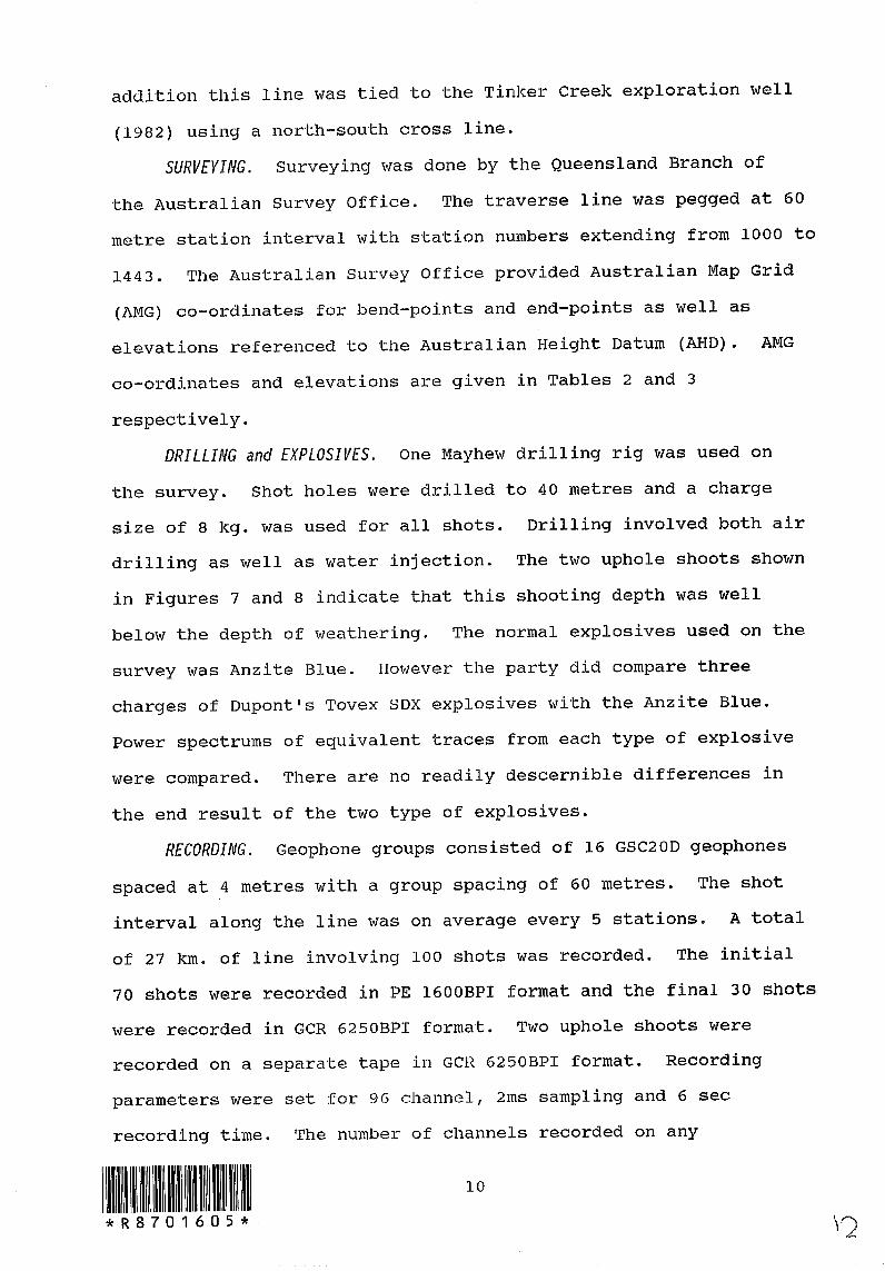
SURVEYING. Surveying was done by the Queensland Branch of
the Australian Survey Office. The traverse line was pegged at 60
metre station interval with station numbers extending from 1000 to
1443. The Australian Survey Office provided Australian Map Grid
(AMG) co-ordinates for bend-points and end-points as well as
elevations referenced to the Australian Height Datum (AHD). AMG
co-ordinates and elevations are given in Tables 2 and 3
respectively.
DRILLING and EXPLOSIVES. One Mayhew drilling rig was used on
the survey. Shot holes were drilled to 40 metres and a charge
size of 8 kg. was used for all shots. Drilling involved both air
drilling as well as water injection. The two uphole shoots shown
in Figures 7 and 8 indicate that this shooting depth was well
below the depth of weathering. The normal explosives used on the
survey was Anzite Blue. However the party did compare three
charges of Dupont's Tovex SDX explosives with the Anzite Blue.
Power spectrums of equivalent traces from each type of explosive
were compared. There are no readily descernible differences in
the end result of the two type of explosives.
RECORDING. Geophone groups consisted of 16 GSC2OD geophones
spaced at 4 metres with a group spacing of 60 metres. The shot
interval along the line was on average every 5 stations. A total
of 27 km. of line involving 100 shots was recorded. The initial
70 shots were recorded in PE 1600BPI format and the final 30 shots
were recorded in GCR 6250BPI format. Two uphole shoots were
recorded on a separate tape in GC R 6250BPI format. Recording
parameters were set for 96 channel, 2ms sampling and 6 sec
recording time. The number of channels recorded on any
ill 11111^1111^10
*R8701605*

***** ,
~:JL....!:1! ~""'::I- "...... ~--~T~ "......, , 443 *~*toE~ :JI v i '''' ~;\ ,
'-.......Ii TW __ '_ ~
DEPTH ...... U1 ...... ...... ru ru w w ~ ~ U1 DEPTH
U1 CS1 U1 CS1
2.121.
I",..
CS1 U1 CS1 U1 CS1
I I
\ . i i;!,' i " \ , . " . i
..... -.. -------.-------------.. -------J-..!..~+-t--~-~- .. -~-~- .. -~-.- .... i--------~4-- ... ---~- .. -r-7--~-~-\ I'
--------.-------------.. ---.. ----------J--t...;..-~ .. Ii I! r I! i
--------------------4----··---····-·-i-~T-:-i:
) ~ ,
::::: j::~;~ct,j~:C::; .. ::t::::::j::t~::-:--::: h-;.,. i'~"'-' ; ... ; ... ;., .•.• .,\.:~.:r .... : ..... ~.~.:.-7~··'···r·'T··~· .. ;.( .................................... . , ,
f' -I i !, I I Ii: I \ I '1 ':', ", II " iF I: 1'1
, ... ; .. { ..... - .~.: ... ,.j.: ... : ... I -~.~.\ ••• ;.; ••• ;.~.;.--\, •• :.~.:.;.: ••• ~ •••• T .................................. . .................................... ·~·.:.-·~! .. ··:·'·;· ...... ~-~·~·'·'·:·I·'· .... ,. -_..... .: ... :., ..... .,..,. .. ' ....... :.: ... ;.~.t-................................. ..
: ; '; : ':., !. • I
-------------------------- .. ----------~--~-~-----~-:-":'~-.-_.--.. -.---- .. -----... _."-"-." ---.--- , -.--- .. -.. -...... --- -------_ .... ----- ..... -.0;-"-----------------------------------
26/ G55 - 13/.9
Fig. 7 Uphole shot station 1443
11

OI/rJ-9!i!;/92
I!I".
Hld3G Ln Ln
***** S221
Ln en
Ln ru
Ln
-Ln-
NOI1~lS ~ lOHS ~lOHdn *****
II'"'
""."
Hld3G

shot varied continuously along the line with the minimum number
accepted being 72 and the maximun 96. This mode of operation was
a compromise between obtaining a maximum amount of data and
efficiency of operation. The delay between actual time-break and
the trace break recorded on camera and magnetic tape was measured
using a detonator. This delay is less than 2 ms and hence can be
ignored in future.
A description of the abbreviations normally used for the
units of the SN368 and how these units are deployed in the field
is given below.
MCU^Master Control Unit
CSU^Cross Station Unit
Su^Station Unit
PSU^Line Power Supply Unit
TB-UH^Time Break-Uphole Unit
UNIT^DEPLOYMENT
MCU and CSU Recording Cab. (Fixed mounting)
PSU^These are stationed on the ground at every 40
station units and are moved when adjacent
geophone sets and station units are lifted for
normal transport to the front of the line.
Power for the units is supplied by a 12v car
battery which is placed on the ground beside the
unit. No power is consumed by a PSU until the
line is activated by the MCU. It is expected
that a fully charged battery will last 3 days
before recharging is necessary. Low or faulty
power on the line is signalled by beeps or
continuous beeping. This audible signal can be
13J ) III 11 00

TB-UH
SU
CABLES
heard using the telephone handset plugged into
any of the line units.
This unit is permanently carried on the shooting
truck and is plugged into the line wherever a
shot is required. The shooter arms the blaster
and advises the observer. The SN368 then fires
the shot. The installation of the shot-firers
equipment must be installed on the rear of the
vehicle on the drivers side. (THIS IS EXTREMELY
IMPOR'rANT)
These are installed at each geophone station and
are transported in special boxes on the
jugwagons.
The individual 65m cables are tied together with
rope or with their own cable. (NOT WITH THEIR
DUST COVERS). The cables are then deployed in
much the same manner as in the old DVSIV system.
The shortest time interval between shots on the Millmerran
survey was 7 minutes. This is about the same time required to
pick up 5 to 6 station units, cable and geophones using two
vehicles with two persons in each vehicle. THE· RESULT OF THIS
TIMING CHECK IS THAT TWO PERSONS WOULD TAKE 120 MINUTES TO PICK UP
90 STATION UNITS AND CABLES. IT WOULD TAKE SLIGHTLY LONGER TO LAY
DOWN THE SAME AMOUNT. The deployment of station units and cables
would be slightly more efficient when these items are layed out on
the driver's side of the traverse. The work involved with cables
and station units is not strenuous but it is time consuming
because of the stop-start situation at each geophone station. The
costs of the station units and cables demands that such items of
equipment must be picked up at night in any area of high
14 \ c Q

population density. In order to make such field procedures
practical it is important that four geophonne carriers be used on
future surveys. The new Sercel cable is much lighter than that
used with the DFSIV 48 channel equipment and will not require 30
cwt vehicles for transport. It has been determined that Toyota
flat tray diesel utilities will be suitable as geophone carriers
provided four units are available.
SOFTWARE. Software modules 210, 211 and 212 which test
equipment performance were run at Millmerran and the results
stored on magnetic tape. The following is a list of software
modes which were tried on the survey. Some of these modules are
used frequently every day.
MODE FUNCTION
000
001
Automatic test mode. This routine is
automatically scheduled on power up.
Edit of the context memory. This is used to set
the contents of memory at the beginning of a
survey. Once initial parameters are set then
this mode should not be used again.
004 Prints contents of con·text memory. This would
only be used for permanent recording of all the
data and parameters set for a survey. Otherwise
it is rarely used.
005 and 006 Used to light up or turn off DU. Not used for
normal work.
008 and 009 Used to display time or alter time. It's only
use is to set time if it has changed by an
unacceptable amount.
100 Forming the line. This mode requires at least
one SU connected to the CSU. This mode is
15 \7

always used prior to recording a shot.
-105 and 106 Line power on or off. These modes are
only used to check which is the high or low side
on the CSU.
110 and III These modes find the last SU on either the
low or high side. They are used extensively to
check the integrity of the line in the morning
and when new station units are added to the
front of the line. Mode III is used to look
ahead at the high end of the line to check new
connections and geophone plants. The second
stage of these modes check the pulse test
against values stored in memory.
112 and 113 Displays geophone pulse tests on the camera.
200
201
This is a quick method of checking geophone
connections. Those geophones which are not
connected do not give the obvious display.
Seismonitor mode. This mode'samples the
geophones continuously and displays the result
on the camera. The program can be used to check
goephone noise. This program is automatically
scheduled during the data acquisition mode.
Data acquisition mode. This program is the one
used to acquire data from all shots. It is
normally used in a chaining mode with mode 100
and is scheduled in the HALT state so that the
shot point information can be entered and
recorded on tape. Tape by-pass may be used with
this mode if for example a test detonator is
being fired and tape recording is not desired.
16 \'2>

210
211
212
220
221
222
223
260
261
Instrument noise to tape. MONTHLY TEST.
Pulse test on resistor to tape. MONTHLY TEST.
Pulse test on geophone to tape. MONTHLY TEST.
Record sine wave, 3.9 Hz, 7 V. This oscillator
test is probably not essential because of the
low frequency.
Record sine wave, 31.2 Hz, 7 V.
Record sine wave, 31.2 Hz, 22.6 uV.
Record sine wave, 31.2 Hz, 181 uV. Modes 221 to
223 are all suitable for the daily oscillator
test.
Burst record. This program records an ID BURST
at the BOT mar]<.er of a new tape. The program is
essential when a new tape is iristalled. Also
this program can be used in tape by-pass mode if
the lo~d key was accidentally pressed while
using a tape previously initialised with a
burst. The burst is an ID on the magnetic tape
which allows other tape transports to identify
the format used for recording. The LOAD key
signals to the computer that a tape has just
been loaded and whenever a program requiring
tape recording is run then the program expects
to find an ID burst.
EOF record on tape. This program should be run
when no more records are to be added to a tape.
It is automatically run when the tape detects
the LOW TAPE indicator. The EOF led is set when
this occurs and the operator must check for this
17
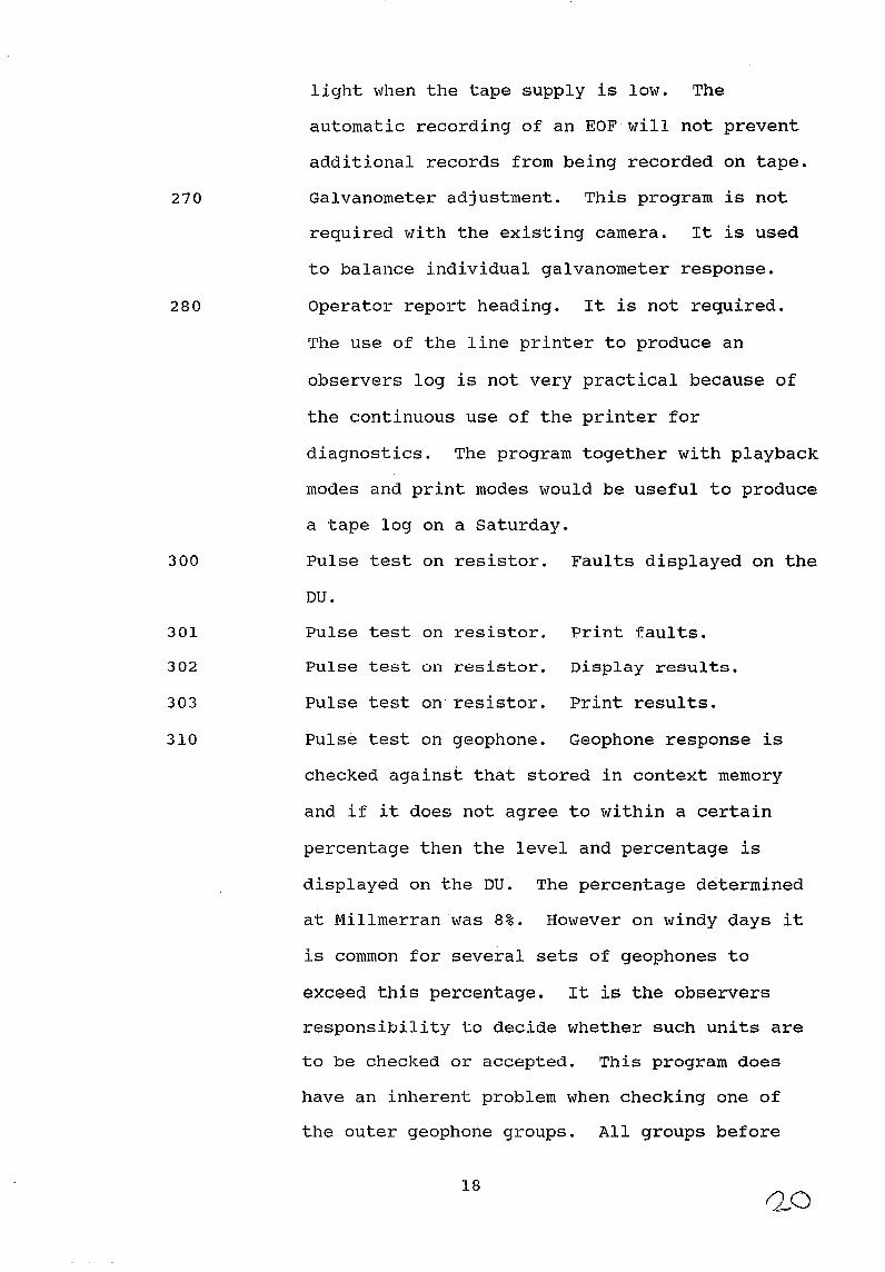
270
280
300
301
302
303
310
lighot when the tape supply is low. The
automatic recording of an EOF will not prevent
additional records from being recorded on tape.
Galvanometer adjustment. This program is not
required with the existing camera. It is used
to balance individual galvanometer response.
Operator report heading. It is not required.
The use of the line printer to produce an
observers log is not very practical because of
the continuous use of the printer for
diagnostics. The program together with playback
modes and print modes would be useful to produce
a tape log on a Saturday.
Pulse test on resistor. Faults displayed on the
DU.
Pulse test on resistor. Print faults.
Pulse test on resistor. Display results.
Pulse test on resistor. Print results.
Pulse test on geophone. Geophone response is
checked against that stored in context memory
and if it does not agree to within a certain
percentage then the level and percentage is
displayed on the DU. The percentage determined
at Millmerranwas 8%. However on windy days it
is common for several sets of geophones to
exceed this percentage. It is the observers
responsibility to decide whether such units are
to be checked or accepted. This program does
have an inherent problem when checking one of
the outer geophone groups. All groups before
18

311
312
313
314
320
321
this one must be checked before hand. This
problem would be alleviated if a 9600 baud VDU
was used to dump results from the pulse test
instead of a relatively slow printer.
Pulse test on geophone. Print faults. Both
modes 310 and 311 are used extensively
throughout the day.
Pulse test on geophone. Display results on the
DU.
Pulse test on geophone. Print-results.
store geophone test in context memory. This
program was run at Millmerran in May 1986 using
96 station units and geophone groups. It should
not be used again unless the battery supply to
the context memory has died. If such is the
case then these values may be returned to memory
by running the program again or by storing the
values shown in Table 1, Zone 4 into context
memory using mode 001. Note that it requires at
least 4 hours to set up a line specifically to
run this mode. Fig. 9 is a pictorial
representation of the response of the geophone
to the pulse test.
station unit noise and offset test. This
program will check the noise and offset level
from all station units and display faulty ones
on the DU.
SU noise and offset test. Print faults. This
is a check of station units and should be run
whenever units are suspect.
19

N o
+1233
700
500
200
100
o I / b i / 1 3
-100
-200
-500
-700 -722
Samples 3,6,28 selected
0/0 Erra r dete rmined 9 0/ 0
8 Hz low cut filter
+96
"'- ..... -" 28 30 90 60 60
Fig.9 Plot of the average amplitude of the impulse response on geophone (Mode 314) 26/G55·· /3/4

322^SU noise and offset test. Display results.
323^SU noise and offset test. Print faults.
380^Print test header. Not used.
400^Magnetic tape, search forward.
401^Magnetic tape, search back. This can be used to
rewind to the BOT by specifing a very large file
number.
402^Magnetic tape, automatic search.
403^Magnetic tape, playback last record. This
program is currently always used in conjunction
with the block number set on the DU. It will
not be required as frequently when a 96 channel
camera becomes available.
404^Magnetic tape, playback first record
encountered.
405^Magnetic tape, continuous playback. This
program is of only limited use.
410^Magnetic tape, return into the gap following
the last record. This program will have to be
used if the LOAD button was accidentally pressed
and the tape moved forward looking for a tape
burst.
411^Magnetic tape, return to gap preceding last
record. This program is rarely used.
412^Magnetic tape, Erase last record. This program
is best left alone as the potential for error is
great.
Il l ,1^71^11 ! 1,^21

Problems encountered with the software included the following.
1. RSI Address 118 in con'text memory does not work unless the
INCREMENT is set to a negative number.
2. Chaining mode will loop on request for a second identical
mode.
e.g. 3220
A403
A22l
A403
A222
A403
This sequence will continually loop on the call to "A221"
3. with PBGN set to 2 in context memory the camera delay-off set
in context memory is ignored and a longer paper feed at the end of
the record is given when running a playback mode (e.g. 403).
4. The Observer's report to the printer is not very practical.
When the Observer's report header is written, the ORGE flag in
context memory is reset. This causes the observers report not to
print time. The ORGE flag in context memory must be set to
correct this situation.
5. When the power to the printer is turned off a new page feed
command is automatically sent to the printer.
6. On two occasions the magnetic tape refused to record and the
error code stated that a tape burst could not be found. This
22

error is suspected to be the result of an unintentional press of
the load button. The solution to the problem is to position the
tape using mode 410 and then run mode 260 in tape by-pass mode.
The tape should now be ready for the next recording.
7. Trouble was experienced with mode 401 when the tape was
positioned close to the EOT marker. The program found the EOT
marker and stopped. Program 402 was used instead and worked well.
HARDWARE. Difficulties experienced with hardware were confined
almost entirely to anciliary equipment. These problems arose
because of ignorance of the system requirements and ignorance of
mode of operation. specific hardware problems and general
comments on hardware are given below.
1. Tape Transport. A faultyIC was replaced during the change
over from PE format to GCR format. The tape transport has been
calibrated to use only "CONTROL DATA storage Master" 1200 ft tapes
and only this brand of tape should be used.
2. Blasters. The INPUT/OUTPUT blaster normally used with the
DFSIV system was not suitable for line shooting with the SN368
system~· This blaster operates at 800v and produces cross-feed in
the Sercel cable as well as the uphole circuit. Currently this
blaster does not work for radio shooting off the end of the line
and the problem will have to solved before long off-set shooting
is possible. The BC8A blasters can be made to work on the line
and the output voltage (450v) does not produce cross-feed.
However these blasters are close to 20 years old and most of the
electronic components have aged. Hence their reliability is
23

questionable .'1'he blaster which \vas used successfully on the
survey was an OYO blaster llired from SeisThic Supply. This blaster
operates at 150v and does not produce cross-feed. fwo of these
units have been recommended for purchase since the completion of
this survey.
3. Radios. The radios used on the line for communication between
the observer and line crew suffer from interference transmitted by
the Sercel cable as well as the electronics in the recording
trucJc. The Sercel cable conducts a 4 MHz signal during line
operations. The effect of this transmission is that the line
crew, sitting in vehicles on the line, cannot hear any
transmission from the recording cab when the line is active. This
does not occur at every location on the line and at the moment the
phenomena is not fully understood. The radio interference
inherent in the recording cab can be severe and may pose a major
problem to radio shooting in future.
4~ Geophone Racks. The geophone racks on the jugwagons must be
modified to prevent the thin cable from snagging at the bottom of
the bin.
5. Test Geophones. The mos·t common practice of testing a
suspected combination of station unit and geophone set is to
replace the geophone set. This function will be made more
efficient if a single geophone, correctly damped, is installed in
each line vehicle.
6. Reported Errors. Several errors were reported during the
course of recording the 100 shots. All of these errors were
24

confined to the initial part of the survey and while the tape
transport was in PE 1600 BPI mode. These errors are listed below.
SP 1043 line parity error.
SP 1154 tape parity error 2, syncro 1.
SP 1244 error 7A15 "13", start of scan error.
SP 1248 error 7A15 "13", start of scan error.
6 DATA PROCESSING
Data from the test survey has been processed at the BMR using
the DISCO system. A final stack section is shown in Fig. 10.
Full scale section (vertical scale, locm/s and horizontal scale,
9. 84traces/cm) will be made available through the Copy Service,
Australian Government Printer (Publications).
The most time consuming step in the data processing was the
demultiplexing of the field data. DISCO at the BMR does not have
the software to demultiplex SEGD (SERCEL format) data. The 1600
bpi, PE magnetic tapes were read and demultiplexed on the Field
Processing System and data transferred to the DISCO in SEGY
format. The 6250 bpi, GCR tapes were demultiplexed by contract
(GSI, Sydney). A detailed step by step processing stream for the
data is listed below.
25
127

N "' " '" ~ :;;
~ .. !: Q
" _u
:!!~
~ :;;
N~ .. ... "'''' ~ :!
:§
a :;:
Uj
360
340
320
300
280
4 2 o
- 10 -20 - 30 -40
20 l 0
" - 10
~ii
: - :~E : ,R"= i -I~E I VRMS I TIME VRMS I TIME VRMS
I 2 , '402 0 ' 2400 1 0 2400 I 0 2400 i 4 ,0 ' 24 70 ( I 420 2640 400 2590 450 2800 II ~~~ , ~~~~ i §~~ ~~i~ 560 2670 8 00 29 40 850 2920 940 3 130
~ 970 1 39 3~ i 950 3050 96111 3080 1050 3280 41110111 ! 5<100 1250 3800 1050 3330 1130 3420
, 2450 4390 2000 4580 1800 438 0
TIME VRMS
2 2 400 375 2730 500 276111 77 5 2940 870 2990
1050 3760 4000 5000
T "(ME : VRMS 1 TIM !.: VRMS TIME VRMS TIME , VRMS TIME VQMS
0 2400 0 2 400 111 2400 111 241110 430 2680 430 2690 , 5 111 2630 400 27 70 580 2752 550 2790 c50 2757 5 25 2930 8 00 2980 650 2840 400 2765 750 301110 9111 0 3090 8 75 308 0 550 29 40 825 31 10
12 40 3800 1150 3680 8 20 . 3070 1600 4240 2000 4410 1530 4200 1040 3560 1925 4600
4000 5000 4000 5000 4000 5000 2950 4630 2510 4750 1570 4220 4000 5000 4000 5000 4000 5000 4000 5000
I
~: :E:i':i:: :t=~~Gt§isi ITIl llffllfHll ll i 1II IIIIIffiIl1III!Il1111 11 11111 11 11 11111 m iii i III i I rn 111 1 i 111111 I 11 iii 11 11 111 11111 11 1 iii I I ~ I i ill i ~ IW. ~
= == = 1\(
F = = ~Z ...-=>. vv= -='=0-<'= 50 l!i Is;;;
1,'1 ' ;
" "I,'
Fig .IO Seismic section
360
340
320
300
280
- 10 - 20 -30 - 40 20 10 o -10 -20
z o >-a: > OJ ...J W
o d l.L
BURERU OF MINERRL RESOURCES
SURVEY RRER
SN 368 EQUIPMENT TESTS 19E MILLMERRRN. QUEENSLRND
LINE STRTIONS:
FINRL
1 1121121121-1443
STRCK EAST
RECORDING PRRRMETERS SI-OT BY I 8t"R
SYSTEt1 TYPE : SERCEL SN36B TF=PE F~T t SEGO DENSITY I 16000PI . PE I:R
, 62508P [ . GCR RECOOO LENGTHI S SECCNJS SR"IPt£ RATE : 2 MSEC
FI LTERS I LCF 8HZ . IBC8lOCT • I-CF 178HZ. 7aEIOCT : NJTQ-l a.rr
CFlTE I ,..::IY - ...........:: 1986
so....RCf: TYPE : !J'f!'.A'1ITE o-t=RGE l e. 2 KG CEP'TH ' .....
SP INTefVR.. I 3612t1 (AVE ) sPRERJ PRTTCRN: VMII=8..£ NJ CF ~I 12 - $ HRX. CFFSETS I 2161i!J'1 - S71iU'1 GRO..P ffiTIERN I 16 IN-t..H£ . 4M eFA:I~ GRCLP I NTCRVfl.: 6W1 CIJVERR3E : 10li!la%
: !
: 1 , ! i ,
; , , I
: i ~==================================~~" PROCESSING SEQUENCE
( 1] t:El"\.LTIPLEX: SEGO TO SEGYIOISCO INTERro.A..J
(2] GEIl'ETRY a:::FINITlO'll
(3] Gl..R..ITY CCNTRO... OIS"LAYS ~ TRR:E EDITS
( 4) ~ICFl. OIVERGEN:E CORRECTJCf.I
C 5 ] TIt'E VF=R I R'fT GFHN Cll'"PENSRT I CI'\I
cel REFRFCTtCl'\l !5T~T!CS c:t:r'PUTATICJ\I CFmI'1 322t1. V5W-273i7'VS. vw-600N/S
OJ F-K F ILTER: CPEf~:nCR L..E\'.GiH I 256 MS BY i TRR:ES DIF'S ~ I -2121 - -221 HS/TRI=CE FREe. PI=ISSED I 15-1 sa HZ
• - 2000 2200 - 3200 380i! - 5000
( 91 CIP SCRT FNJ BRUTE STR:K
P!=ISsa:NJ (~TZl 15 - 100 15 - 112121 15 - 1""
IotilTE/llJI~ WT IN s;( B.IX 57. 21.1% 5:;( B.I7.
(1 111] ve....oclTY FN\..YSES ~ RESlo...A... STmIC3
[11] RESUl..R.. STI=ITICS CIl"PlITRTICN FNl F=f'f't.ICRTrcJ~ ( l~T PRSSJ
[12] IIEl....CCITY ~ YSES F=FTER RES I Cl.A.. STPTtCS
( 13) RE31!l..R... STRTICS Cl:J"PUTATICf.I FNJ FF'PLICRTICN (2N) PRSS}
( 14] ~ t"OVEruT ~TICN
US] pcsT-sn:O( N"'O P'tJTE (20'/. STRETDiJ
CI S] EA....FN:IN3 C7 TRR:E R"f'LI~ (s:R...AR BASED CI'\I :3 ~c W!I'.QCl.l)
( 17] Cl:J"tU.I CE:PT1-I POINT STR:K
Cl e] ERC"ASS F [L TER
Tlf'"E (SEC ] ... ~s (HZ115...CI"'E (CI3/OCTRIIE] 2111/33 - BIiV"E 1.. 15/33 - 60/36
2 .• 15/36 - 40/36 •. S 10/36 - ~/36
(1 9] TIJ"'E V~If'.G Ea.A....I~TICI'\I (GRTE L.E:J"Gr"H ~J
( 2211 0ISPl..R'Y
PROCESSED BY: BURERU OF MINERRL RESOURCES.
GEOLOGY RND GEOPHYSICS CFl'J8ERRR. R. C. T .
OUALITY CONTROL CHECK GECPHYSICISTS , MI KE SEXTet<
I ORVID ....o-f\!ST'CJ'.E
DATE NOV 1986 I"OII'IZDN'!R.. s:R,.L. !IB.~ ~
Ui!l0.a~ItO-I n 01 .. 1161.2,.11 [ 1 H£M ... 3ZBJ. 1I pill
\<6tT1CFl.. ~ I '.335 OVsa: , L 'l~ IN/ SEC
, -Vf~~.~~OJ~ ."..,....,
t-ORI'A.. !EG ~U:J"1
26/~6-
,
I I I • 1 !
!j : I · I
! , I
1 , , 1 I
· , · I !
· ,
· , , . , !
! I ! I
: I

1. Demultiplex: SEGD to SEGY (DISCO internal format)
2. Geometry definition
3. Quality control displays and trace edits
4. Spherical divergence correction
5. Time variant gain compensation
6. Refraction statics computation
datum=320m, VSW=2700m/s, vw=600m/s
7. F-K filter:
operator length = 256ms by 7 traces
dips passed^= -20 - +20 ms/trace
freq. passed^= 15 - 150 Hz
8. Minimum phase bandpass spiking deconvolution
operator length - 256ms
TIME GATES (ms) PASSBAND^WHITE NOISE
(HERTZ) OUT IN
0 - 2000 15 - 100 5% 0.1%
2200 - 3200 15 - 100 5% 0.1%
3800 - 5000 15 - 100 5% 0.1%
9. CDP sort and BRUTE stack
10. Velocity analysis before residual statics
11. Residual statics computation and application
(first pass)
12. Velocity analysis after residual statics
13. Residual statics computation and application
(second pass)
14. Normal moveout correction
15. Post stack NMO mute (20% stretch)
16. Balancing of trace amplitudes
(scalar based on 3 sec window)
17. Common mid-point stack
III a^11^11, 11 1,, 27

18. Bandpass filter
TIME (sec) BANDPASS Hz/ SLOPE (dB/octave)
0.0 20/36 80/36
1.0 15/36 60/36
2.0 15/36 40/36
4.0 10/36 40/36
19. Time variant equalisation (gate length = 400ms)
20. Display
7 RECOMMENDED PROCEDURES
The authors have endeavoured to set up a recommended set of
procedures related to daily tests, routine operations and long
term checks. These are not meant to be taken as absolute
necessities and will undoubtedly be modified as more experience is
obtained with the equipment.
DAILY TEST. The morning daily test should be one of modes 221,
222 or 223 with the record length set at 2 seconds. This
oscillator test must be recorded on magnetic tape and will
effectively check camera alignment, LSI 240 CPU operation and the
tape read after write electronics. The test checks all of the
system with the exception of the LI and LS interface boards and
the station units. It is recommended also that this oscillator
test be inserted at the beginning of each new tape. In order to
check the remainder of the system the operator should use mode 322
and retain the printout for inclusion with the observers reports.
28
So

MONTHLY TESTS. Modes 210, 211, 212 and 320 are suitable for
equipment 'tests recorded on separate magnetic tape at intervals of
one month.
PRESURVEY ELECTRONICS CHECK. It is recommended that wave shapes
and voltage levels in the tape transport be checked prior to the
commencement of a survey.
ROUTINE OPERATION. The following procedure can be used as a guide
for routine operations.
LINE CHECKING. Modes 110, Ill, 112 and 113 are suitable for
checking the line. RECORDING. Modes 100 can be used to form the
line and can be chained with mode 201 for production recording.
In the event of errors being reported during production it is
recommended that a single instantaneous electric detonator be used
to simulate a shot rather than risk losing more charges through
equipment faults. The record length can be set to one second for
such testing and the tape by-pass used if the error is not related
to the tape.
8 CONCLUSIONS
The test survey was a success and the SN368 equipment proved
reliable and superior to the DFSIV. The system versatility is an
important attribu'te with this type of equipment. currently
members of the seismic section acknowledge that their experience
29

with this equipment is limited and that several surveys will be
reguired before the situation changes.
It is recognised by the authors that, because of the
complexity of operating modes, a certain degree of dedication will
be required by future operators.
Technical personnel who ultimately will be responsible for
the maintenance of this equipment must be proficient with all
operating modes and the only opportunity available for them to
achieve this is to operate the equipment for extended periods of
time,during routine production. That is to say there is an urgent
need for technical personnel to operate the equipment for several
months on a production survey.
The technical maintenance of the SN368 equipment will require
technical personnel to have a complete knowledge of operating
modes, be able to manage normal acquisition of seismic data, be
proficient at electronic repairs and eventually develop a
knowledge of computer programming using the LSI-240 asembler
codes.
Some doubts still exist on the deployment of station units
and cables. These items of equipment are expensive and would be
subject to theft or vandalism if exposed to the general public.
Only further field experience will provide a solution to this
problem.
The new Sercel cable is much lighter than that used with the
DFSIV, 48 channel system and there is not a requirement for a 30
cwt vehicle to be used as a IIjugwagonn • It has been determined
that Toyota flat tray diesel utilities will suffice as fljugwagonsfl
provided 4 units are available. The use of 4 vehicles will enable
the deployment of both cables and stations units to be efficient.
30 0.2 ~)

9 ACKNOWLEDGEMENTS
The Bureau of Mineral Resources acknowledge the invaluable
assistance provided by Geoff Bell from Seismic Supply during his
stay with the survey party. The cooperation of the staff at the
western Cree){ forestry st:ation was also much appreciated.
10 REFERENCES
WAKE-DYSTER;K.D., & JOHNSTONE,D.W. 1985 - Southeast Queensland
seismic survey, 1984: Operational Report: Bureau of Mineral
Resources,Australia, Record 1985/42 (unpublished)
CONVERT, J.P., DeVAULT, J.L., & PIEUCHOT, M. 1979 - System aids
field testing of geophones: oil and Gas Journal, Nov. 5, 1979.
CONVERT, J.P., DeVAULT, J.L., & PIEUCHOT, M. 1976 - Telemetry
offers simplicity, accuracy: oil and Gas Journal, Oct. 25, 1976.
EXON, N.F. 1976 - The Geology of the Surat Basin: Bureau of
Mineral Resources, Australia, Bulletin 166.
31

11 Appendix 1 SN368 equipment 1 ist, June 1986
ITEM
Central control unit
Master control unit
Power··Supply
')isplay.Unit
Magnetic Tape PE-GCR
Epson LX-80 Printer
Inverter 12V to 240V
( Invertech INV-I00-VA)
Cross station unit
Time break-Uphole unit
Line Power station unit
Station units
QUANTITY
* 1
* 1
* 1
* 1
* 1
* 1
* * 1
* 2
* 2
* 4
* * 109
*
* Cables, 65 metre, DR8 plugs * 96
Take-outs * 101
Camera--SIE ERC 10C * 1
LSI ]{eyboard
Spares kit A
Spares kit B
Spares kit tape transport
* * 1 set
* 1 set
* 1 set
32
* *
* * * *
* * *
* * * * *
* * * *
*
*
* *
8ERIAL NUMBER8
17
17
17
17
029779
2425
CSU44, CSU168
TBUH113, TBUH152
P8U195, P8U196,
P8U352, P8U353
SU3403 to·8U3460
8U6436 to 8U6451
8U6286 to 8U6320
26608
17

12 Appertdix 2 Operational statistics
Drilling commenced
Recording commenced
Drilling completed
Recording completed
Subsurface coverage
Recording days
CDP fold (average)
Total number of sho·ts
Explosives
Detonators
Charge size
Rig days
Metres drilled
33
22-05-1986.
26-05-1986.
11-06-1986
12-06-1986
27 km
11
10
100
800 kg
125
8.2 kg
16
3660 meters

13 Appendix 3 Spread and recording parameters
Spread length
Number of channels
Geophone station interval
CDP fold
Geophone pattern
Recording mode
Format
Number of input channels
Record unit length
Record length in UNITS
Sampling rate
pre~amplifier gain
Notch filter
Low cut filter
High cut filter
AGe settings
Slope 3
Seis gain 18
Output adjust 5
Release time 40
Compression delay 8
Recovery delay 32
ms
dB
ms
34
varied to 6 km
96
60 m
10
16 in line 4 m appart
PE 1600BPI
GCR 6250 BPI.
SEG-D
96 data, 4 auxiliary
1024 ms
6
2 ms
42 dB
out
8 Hz
178 Hz
36

14 Appendix 4 Personnel and vehicles
PERSONNEL
Party leader
Party manager
Geophysicists
Technical Officers (Engineering)
Technical Officers (science)
Field Assistants
Field Hand
Mechanic
Drillers & Assistant
seismic Supply Representative
VEHICLES
F.J. Taylor
J.A. Somerville
M.J. Sexton
D.W. Johnstone
G. Jennings,C. Rochford
J. Whatman
G. Price,D.E. Pfister
R.D.E. Cherry,A.C.Takken
S. Howard
R .Hazelwood
A. Crawford
T. Shanahan,S. Hancock
G. Bell
Recording truck 1 x International D1610
Workshop truck 1 x Mercedes Benz 911 4 x 4
Computer . truck 1 x Interna'tional Acco 2 x 4
Drilling rig 1 x Mayhew 1000/Mack 6 x 8 truck
Drill water tanker 1 x Mack R875, 6 x 6, 1900 gallon
Shooting truc]c 1 x 'Toyota, tray top, 4 x 4
Personnel carriers 2 x Toyota Troop Carriers, 4 x 4
Geophone carriers 3 x V8 Jeep, 4 x 4
Pre-loading truck 1 x Toyota, tray top, 4 x 4
35

15 Appendix 5 DRE, SN368 vocabulary numbers.
Department of Resources and Energy, Vocabulary
of stores, SN368 vocabulary numbers.
SEISMIC DATA ACQUISI'rrON TELEMETRY SYSTEM "SERCEL" SN368
XDI-200 CENTRAL CONTROL UNIT CCU, COMPRISING: MASTER CONTROL
UNIT MCU "SERCEL" SN368; POWER SUPPLY UNIT PSU "SER
CEL" SN368; DISPLAY UNIT (CONSOLE) DU "SERCEL"
SN368; PRINTER "EPSON" LX80, SIN 029779; CAMERA
XDI-201 MAGNETIC TAPE TRANSPORT T'l' "SERCEL" SN368, DUAL
DENSITY 1600 BPI PEl 6250 BPI GCR SIN 17
XDI-202 STATION UNITS REMOTE SU "SERCEL" SN368 SIN'S
3403-3460, 6286-6320, 6436-6451 (109 UNITS)
XDI-203 POWER SUPPLY UNIT PSU "SERCEL" SN368 SIN'S 195, 196,
352, 353
XDI-204 SHOT UNIT TBIUH "SERCEL" SN368 SIN'S 113, 152
XDI-205 CROSS STATION UNIT CSU "SERCEL" SN368 SIN'S 44, 168
XDI-206 ACCCESSORIES FOR "SERCEL" SN368, COMPRISING: LSI
KEYBOARD; TAPE SPEED MODULE SET; SPARES KIT A CCU;
SPARES KIT B CCU; SPARES KIT GCR MAGNETIC TAPE
TRANSPOR'lI; MOUN'l'ING IIARDWARE
XDI-207 LINE CABLES, SET, FOR "SERCEL" SN368 (65m LENGTH,
DR8 PLUGS)
ZSD-040 SEISMIC DATA ACQUISITION SYSTEM DOCUMENTATION,
"SERCEL" SN368 COMPRISING:
(1) USER'S POCKET GUIDE
(2) USER'S GUIDE
36
33

(3) MASTER CONTROL UNIT MCU DIAGRAMS AND CIRCUITS
( 4) FIELD S'fATION UNIT CIRCUIT DIAGRAMS
(5) POWER SUPPLY UNIT PSU MANUAL WITH CIRCUIT
DIAGRAMS
(6) DUAL 'rAPE 'l'RANSPOR'l' TT DRAWINGS
(7) DUAL 'l'APE TRANSPORT TT TECHNICAL MANUAL
(8) SOFTWARE MANUALS COMPRISING: LINE; DUMP; TEST;
MONITO(R); SHOT; HELP
37

16 Table 1
contents of the context memory for the shot at station 1263.
DATE 174/86 TIME 10:15:43 VERSION 1.2 PAGE 001
CONTEXT MEMORY ZONE = 0
* ADDRESS * MNEMO * VALUE ** ADDRESS * MNEMO * VALUE * 000 * RNOT * 0000 ** 001 * GNOT * 0000 * 002 * FNOT * 0096 ** 003 * FCPL * 0001 * 004 * FCPG * 1228 ** 005 * LFCI * +000 * 006 * RUPL * 0001 ** 007 * RUPG * 1297 * 008 * PSTA * 5244 ** 009 * RECN * 0089 * 010 * RECL * 0006 ** 011 * DEL * 0000 * 012 * SEAR * 0146 ** 013 * NTRA * 0036 * 014 * SLOP * 0003 ** 015 * GCUR * 0002 * 016 * SMG * 0018 ** 017 * OUTA * 0005 * 018 * RTIM * 0040 ** 019 * CDEL * 0008 * 020 * EARG * 0066 ** 021 * AGC * 0001 * 022 * RDEL * 0032 ** 023 * MODE * 0201 * 024 * GRNU * 0001 ** 025 * LINU * 0001 * 026 * SHIN * 0001 ** 027 * NELR * 0001 * 028 * 'ROL * 0001 ** 029 * ICE * 0001 * 030 * PWRF * 0000 **
CONTEXT MEMORY ZONE = 1
* ADDRESS * MNEMO * VALUE ** ADDRESS * MNEMO * VALUE *
048 * NOL * 0001 ** 049 * NORT * 0096 * 050 * SR * 0002 ** 051 * EXPL * 0000 * 052 * STAC * 0000 ** 053 * PBAG * 0018 * 054 * SCN * 0000 ** 055 * SUC * 0002 * 056 * * 0000 ** 057 * * 0007 * 058 * * 0000 ** 059 * * 0008 * 060 * * 0018 ** 061 * AUCl * 0002 * 062 * * 0000 ** 063 * * 0007 * 064 * * 0000 ** 065 * * 0008 * 066 * * 0018 ** 067 * AUC2 * 0002 * 068 * * 0000 ** 069 * * 0007 * 070 * * 0000 ** 071 * * 0000 * 072 * * 0018 ** 073 * AUC3 * 0002 * 074 * * 0000 ** 075 * * 0007 * 076 * * 0000 ** 077 * * 0000 * 078 * * 0018 ** 079 * AUC4 * 0002 * 080 * * 0000 ** 081 * * 0007 * 082 * * 0000 ** 083 * * 0000 * 084 * * 0018 ** 085 * LPBF * 0012 * 086 * HPBF * 0090 ** 087 * PBGN * 0001 *
38
40

CONTEXT MEMORY ZONE = 2
* ADDRESS '* MNEMO * VALUE ** ADDRESS * MNEMO * VALUE *
112 * SUT * 0001 ** 113 * AUXS * 0001 * 114 * AUXL * 0000 ** 115 * FOTB * 0000 * 116 * TBW * 0300 ** 117 * RECT * 0001 * 118 * RSI * 0000 ** 119 * THFI * 0000 * 120 * RLU * 1024 ** 121 * COON * 1300 * 122 * CDOF * 1000 ** 123 * PBSI * 0000 * 124 * CNOT * 0048 ** 125 * ORGE * 0002 * 126 * PTFI * 0000 ** 127 * CHNI * 0100 * 128 * * 0201 ** 129 * * A403 * 130 * * 0000 ** 131 * * 0000 * 132 * CHN2 * 0000 ** 133 * * 0000 * 134 * * 0000 ** 135 * * 0000 * 136 * * 0000 ** 137 * CHN3 * 0220 * 140 * * A403 ** 141 * * A222 * 142 * * A403 ** 143 * * 0000 * 144 * * 0000 ** 145 * * 0000 * 146 * * 0000 ** 147 * LTV * 0003 * 148 * * 0009 ** 149 * * 0006 * 150 * * 0009 ** 151 * * 0028 * 152 * * 0009 ** 153 * GTV * 0003 * 154 * * 0009 ** 155 * * 0006 * 156 * * 0009 ** 157 * * 0028 * 158 * * 0009 ** 159 * UFRT * 0001 * 160 * * 0000 ** 161 * * 0000 * 162 * * 0001 ** 163 * * 0000 * 164 * * 0000 ** 165 * * 0001 * 166 * * 0000 ** 167 * * 0000 * 168 * NSN * 0500 ** 169 * NTT * 0400 * 170 * OFTT * 1000 ** 171 * LPBR * 9600 * 172 * HME * 0000 ** 173 * OFI * 0000 * 174 * MONO * 0001 ** 175 * SSEt * 0000 * 176 * RSD * 0000 ** 177 * GCE * 0001 * 178 '* TELE '* 0000 '** 179 * NRS '* 0024 * 180 * NGW * 0001 ** 181 * NFS * 0024 * 182 * LCP * 9999 ** 183 * AUTI * 0000 * 184 * EGLK '* 0036 ** 185 * OALK * 0004 * 186 * EBLA * 0000 ** 187 * SPNL * 0001 * 188 * SPNG * 1263 *'* 189 * * 0000 *
39

CON'rEx'r MEMORY ZONE = 4
* ADD * VALUE "'* ADD * VALUE ** ADD * VALUE ** ADD * VALUE *
* 300 * +0000 ** 301 * +0189 'k* 302 * +1233 ** 303 * +1086 * * 304 * -0689 ** 305 * -0722 ** 306 * -0270 ** 307 * -0346 * * 308 * -0345 ** 309 * -0278 ** 310 * -0242 ** 311 * -0206 * * 312 * -0167 ** 313 * -0132 ** 314 * -0098 ** 315 * -0067 * * 316 * -0039 ** 317 * -0014 ** 318 * +0008 ** 319 * +0028 * * 320 * +0045 ** 321 * +0059 ** 322 * +0071 ** 323 * +0080 * * 324 * +0087 ** 325 * +0092 ** 326 * +0095 ** 327 * +0096 * * 328 * +0096 ** 329 * +0094 ** 330 * +0091 ** 331 * +0087 * * 332 * +0082 ** 333 * +0076 ** 334 * +0070 ** 335 * +0064 * * 336 * +0057 ** 337 * +0050 ** 338 * +0043 ** 339 * +0036 * * 340 * +0029 ** 341 * +0023 ** 342 * +0016 ** 343 * +0010 * * 344 * +0005 ** 345 * +0000 ** 346 * -0004 ** 347 * -0009 * * 348 * -0013 ** 349 * -0016 ** 350 * -0019 ** 351 * -0022 * * 352 * -0024 ** 353 * -0026 ** 354 * -0027 ** 355 * -0028 * * 356 * -0029 ** 357 * -0029 ** 358 * -0029 ** 359 * -0028 * * 360 * -0028 ** 361 * -0027 ** 362 * -0026 ** 363 * -0025 * * 364 * -0023 ** 365 * -0022 ** 366 * -0020 ** 367 * -0019 * * 368 * -0017 ** 369 * -0016 ** 370 * -0014 ** 371 * -0012 * * 372 * -0011 ** 373 * -0009 ** 374 * -0007 ** 375 * -0006 * * 376 * -0004 ** 377 * -0003 ** 378 * -0002 ** 379 * -0001 * * 380 * +0000 ** 381 * +0000 ** 382 * +0001 ** 383 * +0002 * * 384 * +0003 ** 385 * +0003 'k * 386 * +0004 ** 387 * +0004 * * 388 * +0005 ** 389 * +0005 ** 390 * +0005 ** 391 * +0005 * * 392 * +0005 ** 393 * +0005 ** 394 * +0005 ** 395 * +0005 * * 396 * +0000 ** 397 * +0000 ** 398 * +0000 ** 399 * +0000 *
40
4-2

17 Table 2
AMG CO-ORDINATES
EASTING NORTHING LOCATION 1000 262612. 6922835. LOCATION 1038 264874. 6922545. LOCATION 1068 266662. 6922334. LOCATION 1100 268570. G922114. LOCATION 1154 271 '/ 87. G921726. LOCATION 1159 272085. G921687. LOCATION 1211 27518l. 6921302. LOCATION 1225 276016. 6921208. LOCATION 1258 277982. 6920982. LOCATION 1286 27965l. 6920772. LOCATION 1340 282864. 6920354. LOCATION 1380 285245. 692005l. LOCATION 1428 288106. 6919713. LOCATION 1443 288999. 6919607.
41

18 Table 3
ELEVAT~ONS, STA'l'IONS 1000 TO 1443 318.0 319.3 320.8 322.1 323.3 322.6 321. 3 320.0
319.5 319.4 319.5 320.0 320.0 318.7 317.7 316.9 316.0
315.3 314.4 313.8 313.3 312.7 312.2 311. 6 311. 0
310.6 310.2 310.1 310.1 310.1 310.1 310.2 310.2
310.1 310.1 310.2 310.2 310.1 310.2 310.4 310.6
310.9 311. 5 312.2 312.8 313.7 314.5 315.3 316.0
316.7 317.9 319.1 320.2 321. 6 322.2 322.4 322.3
321. 9 321. 8 322.1 322.6 323.5 324.1 325.4 327.5 329.2 330.0 330.2 331. 2 330.6 329.9 328.8 328.1
328.9 329.8 329.9 329.7 329.9 329.5 329.9 330.4
330.6 331. 2 332.0 332.8 333.3 334.4 334.9 336.1
337.3 337.8 337.3 338.4 338.9 340.2 340.5 339.5 337.2 334.1 332.1 330.9 329.[1 329.1 328.6 328.0 328.0 328.2 32B.5 329.4 329.U 329.0 328.1 327.1 327.1 326.8 327.4 328.7 329.5 329.5 328.8 327.9
326.5 324.4 320.9 318.0 316.5 316.0 314.6 313.6 313.0 312.0 311.1 310.4 309.5 30B.7 307.8 307.1 306.3 305.7 305.3 305.0 304.7 304.4 302.2 303.7 304.5 305.1 305.1 304.8 305.7 304.5 302.4 301. 3 300.5 298.7 294.8 290.2 297.5 300.9 303.0 303.0 303.B 304.3 304.1 303.8 303.3 302.5 302.4 302.2 303.8 304.6 305.4 306.4 307.1 307.5 307.6 307.3 308.0 309.2 310.5 312.0 313.0 313.7 314.4 314.9 315.4 315.5 315.6 315.8 316.2 316.3 316.5 316.6 316.8 317.1 317.2 316.9 316.6 316.3 316.0 315.6 315.1 315.1 314.7 314.5 314.4 314.1 313.7 313.5 313.4 313.0 312.2 311. 3 310.3 310.5 310.6 311. 3 311. 6 312.0 313.4 314.2 315.0 315.7 316.2 316.6 316.8 316.8 316.3 315.1 316.8 317.3 317.9 318.2 318.5 318.6 319.1 319.3 319.8 320.1 320.4 320.8 321.1 321.2 321. 3 321. 4 321. 7 322.1 322.4 322.7 323.0 323.4 323.7 324.2 324.6 325.0 325.2 325.4 325.2 325.2 324.8 324.9 324.9 325.1 325.5 325.4 325.3 325.6 325.9 325.7 325.4 325.4 325.9 326.3 326.8 326.8 327.0 327.9 328.4 328.3 327.5 327.3 327.6 328.0 327.9 328.3 328.9 329.5 329.4 329.0 328.3 328.1 328.0 328.1 328.1 328.1 328.0 327.7 327.6 327.3 326.5 327.8 328.~j 329.0 329.5 330.0 330.5 330.8 331.1 331. 2 331. 3 331.1 331.1 331. 3 331. 5 331. 7 332.0 332.2 332.4 332.5 332.5 332.7 333.1 333.4 333.6 334.0 334.3 334.5 334.8 335.3
335.6 335.7 336.1 336.5 336.7 337.8 337.5 338.1 338.8 339.4 339.8 340.1 340.5 340.7 340.9 341.2 341.4 341. 7 342.0 342.2 342.2 342.4 342.5 342.6 342.8 342.9 342.9 343.0 343.1 343.2 343.3 343.4 343.5 343.8 344.0 344.2 344.3 344.4 344.5 344.8 344.9 345.0 345.2 345.5 345.5 345.6 345.6 345.6 345.6 345.6 345.5 345.4 345.2 344.6 343.5 344.1
344.4 344.4 344.3 343.7 343.3 342.8 342.4 341.9
341.4 341.4 340.5 339.8 339.5 339.6 339.3 339.3 339.4 339.3 339.1 339.1 339.3 339.9 340.7 341. 2 341. 3 340.8 340.2 339.5 338.9 338.2 337.5 336.7
336.7 336.5 336.2 334.5 336.0 335.8 335.8 335.8 335.8 335.5 335.1 334.7 333.7 332.9 332.5 334.2
335.8 336.5 337.1 337.'1 338.3 339.0 339.9 340.7
341. 6 342.1 342.4
42 4'+