bus: 3-way flanged valve, pn 40 (el.)
TRANSCRIPT
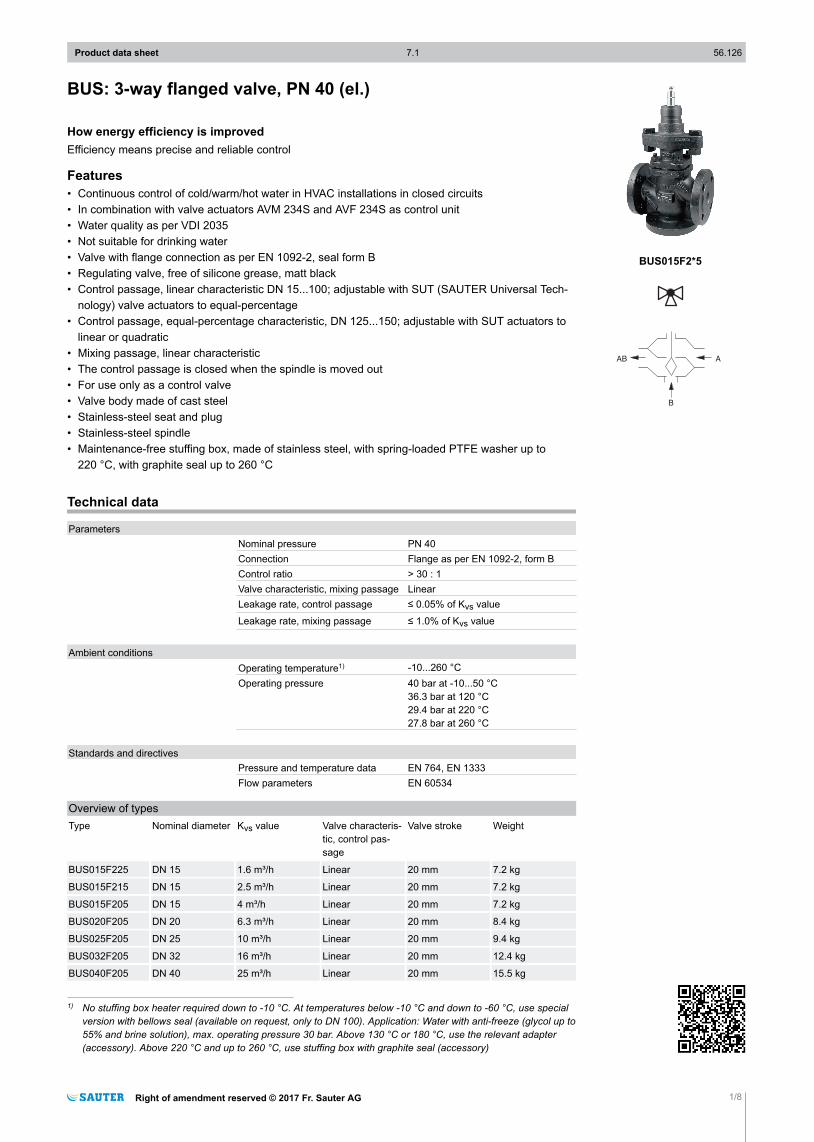
BUS: 3-way flanged valve, PN 40 (el.)
How energy efficiency is improvedEfficiency means precise and reliable control
Features• Continuous control of cold/warm/hot water in HVAC installations in closed circuits• In combination with valve actuators AVM 234S and AVF 234S as control unit• Water quality as per VDI 2035• Not suitable for drinking water• Valve with flange connection as per EN 1092-2, seal form B• Regulating valve, free of silicone grease, matt black• Control passage, linear characteristic DN 15...100; adjustable with SUT (SAUTER Universal Tech-
nology) valve actuators to equal-percentage• Control passage, equal-percentage characteristic, DN 125...150; adjustable with SUT actuators to
linear or quadratic• Mixing passage, linear characteristic• The control passage is closed when the spindle is moved out• For use only as a control valve• Valve body made of cast steel• Stainless-steel seat and plug• Stainless-steel spindle• Maintenance-free stuffing box, made of stainless steel, with spring-loaded PTFE washer up to
220 °C, with graphite seal up to 260 °C
Technical data
ParametersNominal pressure PN 40Connection Flange as per EN 1092-2, form BControl ratio > 30 : 1Valve characteristic, mixing passage LinearLeakage rate, control passage ≤ 0.05% of Kvs value
Leakage rate, mixing passage ≤ 1.0% of Kvs value
Ambient conditionsOperating temperature1) -10...260 °COperating pressure 40 bar at -10...50 °C
36.3 bar at 120 °C29.4 bar at 220 °C27.8 bar at 260 °C
Standards and directivesPressure and temperature data EN 764, EN 1333Flow parameters EN 60534
Overview of typesType Nominal diameter Kvs value Valve characteris-
tic, control pas-sage
Valve stroke Weight
BUS015F225 DN 15 1.6 m³/h Linear 20 mm 7.2 kg
BUS015F215 DN 15 2.5 m³/h Linear 20 mm 7.2 kg
BUS015F205 DN 15 4 m³/h Linear 20 mm 7.2 kg
BUS020F205 DN 20 6.3 m³/h Linear 20 mm 8.4 kg
BUS025F205 DN 25 10 m³/h Linear 20 mm 9.4 kg
BUS032F205 DN 32 16 m³/h Linear 20 mm 12.4 kg
BUS040F205 DN 40 25 m³/h Linear 20 mm 15.5 kg
1) No stuffing box heater required down to -10 °C. At temperatures below -10 °C and down to -60 °C, use specialversion with bellows seal (available on request, only to DN 100). Application: Water with anti-freeze (glycol up to55% and brine solution), max. operating pressure 30 bar. Above 130 °C or 180 °C, use the relevant adapter(accessory). Above 220 °C and up to 260 °C, use stuffing box with graphite seal (accessory)
Product data sheet 7.1 56.126
Right of amendment reserved © 2017 Fr. Sauter AG 1/8
BUS015F2*5
Type Nominal diameter Kvs value Valve characteris-tic, control pas-sage
Valve stroke Weight
BUS050F205 DN 50 40 m³/h Linear 20 mm 19.2 kg
BUS065F205 DN 65 63 m³/h Linear 30 mm 27.6 kg
BUS080F205 DN 80 100 m³/h Linear 30 mm 36.5 kg
BUS100F205 DN 100 160 m³/h Linear 30 mm 61.2 kg
BUS125F305 DN 125 220 m³/h Equal-percentage 40 mm 82.5 kg
BUS150F305 DN 150 320 m³/h Equal-percentage 40 mm 113.5 kg
AccessoriesType Description
0372336180 Adaptor (required when temperature of the medium is 130...180 °C)
0372336240 Adaptor (required when temperature of the medium is 180...260 °C)
0378373001 Stuffing box with graphite seal for temperatures of 220...260 °C; DN 15…50
0378373002 Stuffing box with graphite seal for temperatures of 220...260 °C; DN 65…100
0378373003 Stuffing box with graphite seal for temperatures of 220...260 °C; DN 125…150
Combination of BUS with electrical actuators
/ Warranty: The technical data and pressure differences indicated here are applicable only in com-bination with SAUTER valve actuators. The warranty does not apply if used with valve actuatorsfrom other manufacturers.
/ Definition of ∆p s: Maximum admissible pressure drop in the event of a malfunction (pipe breakafter the valve) at which the actuator reliably closes the valve by means of a return spring.
/ Definition of ∆p max: Maximum admissible pressure drop in control mode at which the actuatorreliably opens and closes the valve.
Pressure differencesActuator AVM322F120
AVM322F122AVM322SF132 AVM234SF132 AVF234SF132 AVF234SF232
Actuating power 1000 N 1000 N 2500 N 2000 N 2000 N
Control signal 2-/3-point2-/3-point, 0...10 V, 4...20 mA
2-/3-point, 0...10 V, 4...20 mA
2-/3-point, 0...10 V, 4...20 mA
2-/3-point, 0...10 V, 4...20 mA
Running time DN15...50
120/240 s 80/120 s 40/80/120 s 40/80/120 s 40/80/120 s
Running time forDN 65...100
– – 60/120/180 s 60/120/180 s 60/120/180 s
Running time forDN 125, DN 150
– – 80/160/240 s 80/160/240 s 80/160/240 s
∆p [bar]
As control valve ∆pmax ∆pmax ∆pmax ∆pmax ∆ps ∆pmax ∆ps
BUS015F225BUS015F215BUS015F205
35.0 35.0 40.0 40.0 40.0 40.0 40.0
BUS020F205 35.0 35.0 40.0 34.7 40.0 34.7 40.0BUS025F205 17.4 17.4 37.8 29.6 37.0 29.6 37.0BUS032F205 12.2 12.2 27.0 21.1 27.0 21.1 27.0BUS040F205 6.2 6.2 16.4 12.8 16.0 12.8 16.0BUS050F205 3.7 3.7 10.5 8.2 10.0 8.2 10.0BUS065F205 – – 6.1 4.7 6.1 4.7 6.1BUS080F205 – – 3.9 3.0 3.9 3.0 3.9BUS100F205 – – 2.5 1.9 2.5 1.9 2.5BUS125F305 – – 1.7 1.3 1.7 1.3 1.7BUS150F305 – – 1.2 0.9 1.2 0.9 1.2Cannot be used as distribution valve
Product data sheet 7.1 56.126
2/8 Right of amendment reserved © 2017 Fr. Sauter AG
A At temperatures above 130 °C, accessories are required
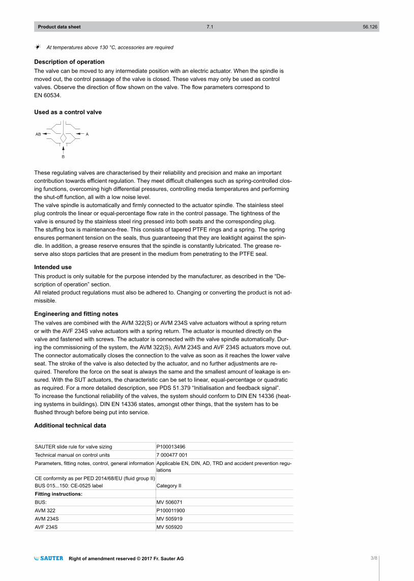
Description of operationThe valve can be moved to any intermediate position with an electric actuator. When the spindle ismoved out, the control passage of the valve is closed. These valves may only be used as controlvalves. Observe the direction of flow shown on the valve. The flow parameters correspond toEN 60534.
Used as a control valve
These regulating valves are characterised by their reliability and precision and make an importantcontribution towards efficient regulation. They meet difficult challenges such as spring-controlled clos-ing functions, overcoming high differential pressures, controlling media temperatures and performingthe shut-off function, all with a low noise level.The valve spindle is automatically and firmly connected to the actuator spindle. The stainless steelplug controls the linear or equal-percentage flow rate in the control passage. The tightness of thevalve is ensured by the stainless steel ring pressed into both seats and the corresponding plug.The stuffing box is maintenance-free. This consists of tapered PTFE rings and a spring. The springensures permanent tension on the seals, thus guaranteeing that they are leaktight against the spin-dle. In addition, a grease reserve ensures that the spindle is constantly lubricated. The grease re-serve also stops particles that are present in the medium from penetrating to the PTFE seal.
Intended useThis product is only suitable for the purpose intended by the manufacturer, as described in the “De-scription of operation” section.All related product regulations must also be adhered to. Changing or converting the product is not ad-missible.
Engineering and fitting notesThe valves are combined with the AVM 322(S) or AVM 234S valve actuators without a spring returnor with the AVF 234S valve actuators with a spring return. The actuator is mounted directly on thevalve and fastened with screws. The actuator is connected with the valve spindle automatically. Dur-ing the commissioning of the system, the AVM 322(S), AVM 234S and AVF 234S actuators move out.The connector automatically closes the connection to the valve as soon as it reaches the lower valveseat. The stroke of the valve is also detected by the actuator, and no further adjustments are re-quired. Therefore the force on the seat is always the same and the smallest amount of leakage is en-sured. With the SUT actuators, the characteristic can be set to linear, equal-percentage or quadraticas required. For a more detailed description, see PDS 51.379 “Initialisation and feedback signal”.To increase the functional reliability of the valves, the system should conform to DIN EN 14336 (heat-ing systems in buildings). DIN EN 14336 states, amongst other things, that the system has to beflushed through before being put into service.
Additional technical data
SAUTER slide rule for valve sizing P100013496Technical manual on control units 7 000477 001Parameters, fitting notes, control, general information Applicable EN, DIN, AD, TRD and accident prevention regu-
lationsCE conformity as per PED 2014/68/EU (fluid group II)BUS 015...150: CE-0525 label Category IIFitting instructions:BUS: MV 506071AVM 322 P100011900AVM 234S MV 505919AVF 234S MV 505920
Product data sheet 7.1 56.126
Right of amendment reserved © 2017 Fr. Sauter AG 3/8
AVN 224S MV 505927Declaration on materials and the environment MD 56.126
Fitting positionThe control unit can be fitted in any position, but the hanging position is not recommended. Conden-sate, drops of water, etc. must be prevented from entering the actuator. With horizontal installationand no structural support for the actuator, the maximum admissible weight on the valve is 25 kg.At a media temperature• Up to 130 °C:
• In any position except suspended.• Over 130 °C:
• At temperatures of over 130 °C or over 180 °C, a horizontal fitting position is recommended, andthe appropriate adapter for the temperature must be used. The adapter can also be used as anextension to come out of the pipe insulation with the actuator. To protect the actuator from exces-sive heat, the piping must be insulated.
When the actuator is mounted on the valve, make sure the plug is not twisted on the stainless steelseat (this can damage the sealing surface). When insulating the valve, it may only be insulated up tothe connecting clip of the actuator.
Outdoor installationWe recommend protecting the devices from the weather if they are installed outside buildings.
Using with waterSo that impurities are retained in the water (welding beads, rust particles, etc.) and the spindle seal isnot damaged, we recommend installing collecting filters, for example one for each floor or pipe run.Requirements for water quality as per VDI 2035.When using an additive in the water, the compatibility of the valve materials must be checked with themanufacturer of the medium. The materials table shown below may be used. When using glycol werecommend a concentration between 20% and 55%.
Other information regarding hydraulics and noise in systemsThe valves can be used in a low-noise environment. To prevent noise, the pressure differences ∆pmax
listed below should not be exceeded. These are listed as recommended values in the table of pres-sure losses.The pressure difference ∆pv is the maximum pressure that may act on the valve regardless of thestroke position, in order that the risk of cavitation and erosion is limited. These values are irrespectiveof the actuator force. The cavitation accelerates wear on the plug and seat in the valve and causesnoises. To prevent cavitation, the differential pressure on the valve should not exceed the value ∆pcrit:∆pcrit = (p1 – pv) × 0.5p1 = upstream pressure before the valve (bar)pv = steam pressure at operating temperature (bar)The calculation works with absolute pressure.For the spring return, the stated ∆ps values are also the permissible differential pressure up to whichthe actuator can guarantee that the valve is closed in the event of an incident. Because this is anemergency function with a fast stroke movement (using a spring), this value can exceed ∆pmax.
Product data sheet 7.1 56.126
4/8 Right of amendment reserved © 2017 Fr. Sauter AG
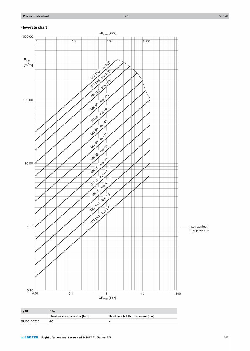
Flow-rate chart
DN150
kvs
320
DN125
kvs
220
DN100
kvs
160
DN80
kvs
100
DN65
kvs
63
DN50
kvs
40
DN40
kvs
25
DN32
kvs
16
DN25
kvs
10
DN20
kvs
6,3
DN15/1
kvs
2,5
DN15/2
kvs
1,6
DN15
kvs
4
1 10 100 1000
1000.00
100.00
10.00
1.00
0.100.01 1 100100.1
∆P [kPa]v100
V100
[m /h]3
∆P [bar]v100
?pv againstthe pressure
Type ∆pv
Used as control valve [bar] Used as distribution valve [bar]BUS015F225 40 -
Product data sheet 7.1 56.126
Right of amendment reserved © 2017 Fr. Sauter AG 5/8
Type ∆pv
BUS015F215 40 -BUS015F205 40 -BUS020F205 40 -BUS025F205 40 -BUS032F205 40 -BUS040F205 40 -BUS050F205 30 -BUS065F205 30 -BUS080F205 25 -BUS100F205 25 -BUS125F305 15 -BUS150F305 15 -
Additional version informationValve body made of cast steel as per DIN EN 10213, code GP240GH+N, material number 1.0619+Nwith smooth drilled flanges as per EN 1092-1, seal form B. Valve body protected by matt paintRAL 9005 black. Recommended for the welding flange as per EN 1092-1. Valve fitting length as perEN 558-1, basic series 1. Flat seal on valve body made of asbestos-free material.PTFE collar and sealing ring for stuffing box available as spare part no. 0378372
Material numbers as per DINDIN material no. DIN designation
Valve body 1.0619+N GP240GH+NValve seat 1.4021 X20Cr13Spindle 1.4021 X20Cr13Plug 1.4021 X20Cr13Stuffing box 1.4021 X20Cr13Seal under stuffing box Cu DIN 7603
Additional details on the definitions of pressure difference∆pv:Maximum admissible pressure difference over the valve at every stroke position, limited by noise leveland erosion.With this parameter, the valve is characterised as a flow element with specific hydraulic behaviour.Monitoring the cavitation and erosion along with the associated noise increases the service life andthe operational capacity.∆pmax:Maximum admissible pressure difference over the valve at which the actuator can reliably open andclose the valve.Static pressure and flow effects are considered. This value ensures trouble-free stroke movement andclosing of the valve. The value ∆pv of the valve is never exceeded.∆ps:Maximum admissible pressure difference over the valve in the event of a malfunction (e.g. power fail-ure, excessive temperature or pressure, pipe break) at which the actuator can close the valve tightlyand, if necessary, maintain the entire operating pressure against atmospheric pressure. Because thisis a quick-closing function with a rapid stroke movement, ∆ps can be greater than ∆pmax or ∆pv. Thedisruptive flow effects that arise here are quickly passed through and are of minor importance in thismethod of operation.For 3-way valves, the values only apply to the control passage.∆pstat:Line pressure behind the valve. This essentially corresponds to the idle pressure when the pump isswitched off, caused for example by the fluid level in the system, increased pressure due to pressuretanks, steam pressure, etc.For valves that close with pressure, the static pressure plus the pump pressure are used.
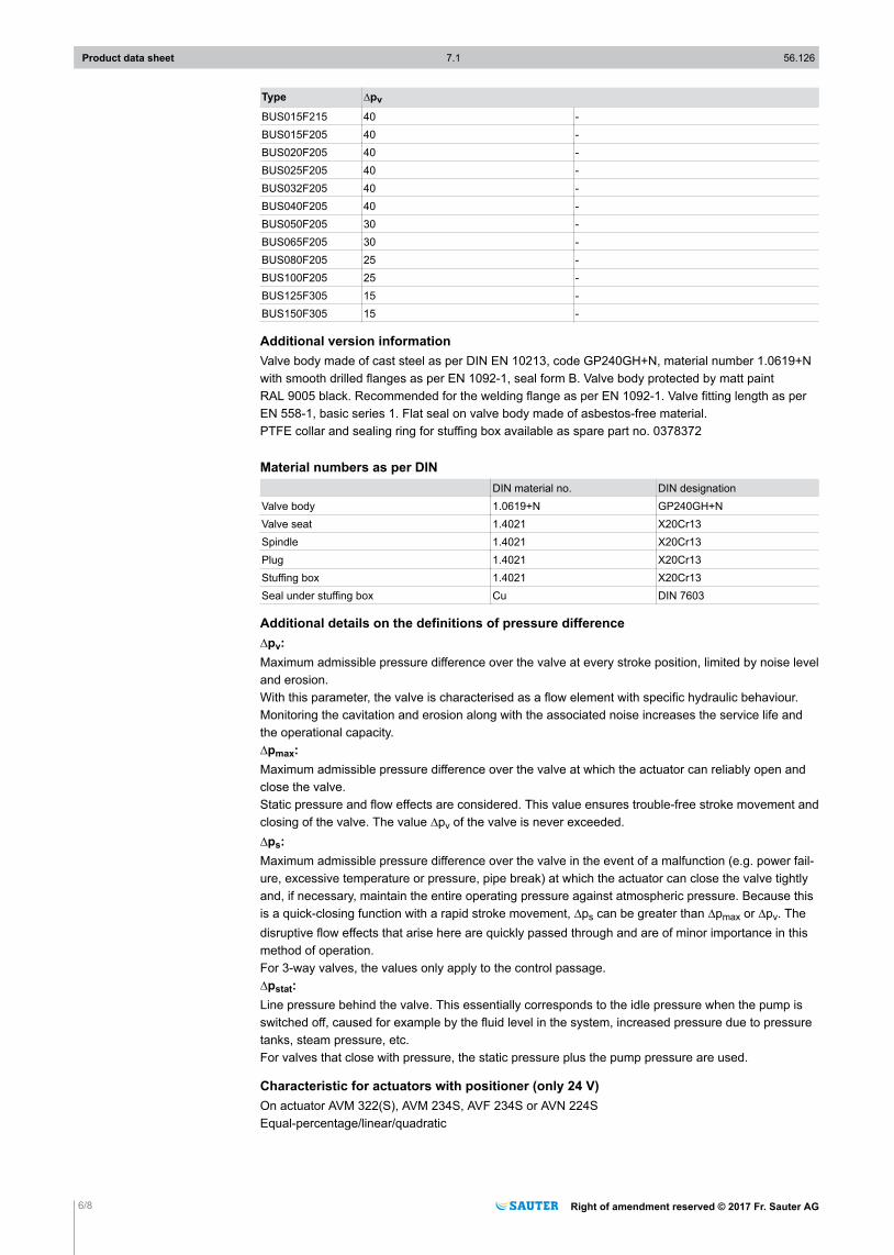
Characteristic for actuators with positioner (only 24 V)On actuator AVM 322(S), AVM 234S, AVF 234S or AVN 224SEqual-percentage/linear/quadratic
Product data sheet 7.1 56.126
6/8 Right of amendment reserved © 2017 Fr. Sauter AG
Can be set using coding switch
DisposalWhen disposing of the product, observe the currently applicable local laws.More information on materials can be found in the Declaration on materials and the environment forthis product.
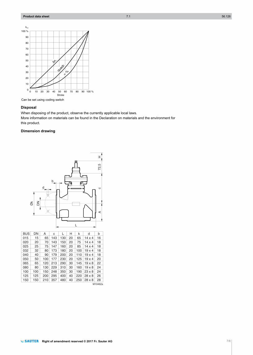
Dimension drawing
L
72,5
H
M10462a
cA
c
143
143
147
173
179
177
213
229
248
295
357
L
130
150
160
180
200
230
290
310
350
400
480
H
20
20
20
20
20
20
30
30
30
40
40
k
65
75
85
100
110
125
145
160
190
220
250
d
14 x 4
14 x 4
14 x 4
19 x 4
19 x 4
19 x 4
19 x 8
19 x 8
23 x 8
28 x 8
28 x 8
b
16
18
18
18
18
20
22
24
24
26
28
DN
Øk
d
b
BUS
015
020
025
032
040
050
065
080
100
125
150
DN
15
20
25
32
40
50
65
80
100
125
150
A
65
70
75
80
90
100
120
130
150
200
210
Product data sheet 7.1 56.126
Right of amendment reserved © 2017 Fr. Sauter AG 7/8
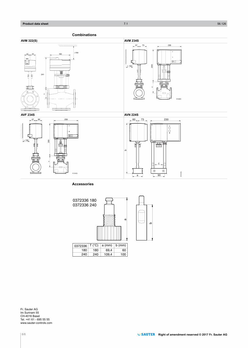
CombinationsAVM 322(S) AVM 234S
4444 160>150
241
c
K10460
230
> 150
289
7357
c
AVF 234S AVN 224S
K10459
230
> 150
28
9
6057
c
M1
04
00
b
b
73 230
a
60
90
c
Accessories
0372336 1800372336 240
a
b
T (°C) a (mm) b (mm)
180 69,4 60
240 109,4 100
0372336
180
240
Product data sheet 7.1 56.126
8/8 Right of amendment reserved © 2017 Fr. Sauter AG
Fr. Sauter AGIm Surinam 55CH-4016 BaselTel. +41 61 - 695 55 55www.sauter-controls.com