bus diverter module (bdm) installation and service instruction · installation and service...
TRANSCRIPT

INSTALLATION AND SERVICE INSTRUCTION
SD39BDM-1Issue: 1July 1994
BUS DIVERTER MODULE (BDM)INSTALLATION AND SERVICE INSTRUCTION
MOORE PRODUCTS CO., Spring House, PA 19477-0900An ISO 9001 registered company

SD39BDM-1 CONTENTS
July 1994 i
TABLE OF CONTENTS
SECTION TITLE PAGE
1.0 INTRODUCTION . . . . . . . . . . . . . . . . . . . . . . . . . . . . . . . . . . . . . . . . . . . . . . . . . . . . . . . . . . . . 1-11.1 PRODUCT DESCRIPTION . . . . . . . . . . . . . . . . . . . . . . . . . . . . . . . . . . . . . . . . . . . . . . . . . 1-11.2 RELATED LITERATURE . . . . . . . . . . . . . . . . . . . . . . . . . . . . . . . . . . . . . . . . . . . . . . . . . 1-2
2.0 INSTALLATION . . . . . . . . . . . . . . . . . . . . . . . . . . . . . . . . . . . . . . . . . . . . . . . . . . . . . . . . . . . . 2-12.1 INSTALLATION CONSIDERATIONS . . . . . . . . . . . . . . . . . . . . . . . . . . . . . . . . . . . . . . . 2-12.2 ENVIRONMENTAL CONSIDERATIONS . . . . . . . . . . . . . . . . . . . . . . . . . . . . . . . . . . . . 2-22.3 EQUIPMENT DELIVERY AND HANDLING . . . . . . . . . . . . . . . . . . . . . . . . . . . . . . . . . . 2-32.3.1 Predelivery Test . . . . . . . . . . . . . . . . . . . . . . . . . . . . . . . . . . . . . . . . . . . . . . . . . . . . 2-32.3.2 Factory Shipment . . . . . . . . . . . . . . . . . . . . . . . . . . . . . . . . . . . . . . . . . . . . . . . . . . . 2-32.3.3 Receipt of Shipment . . . . . . . . . . . . . . . . . . . . . . . . . . . . . . . . . . . . . . . . . . . . . . . . 2-32.3.4 Return of Shipment . . . . . . . . . . . . . . . . . . . . . . . . . . . . . . . . . . . . . . . . . . . . . . . . . 2-32.3.5 Equipment Handling . . . . . . . . . . . . . . . . . . . . . . . . . . . . . . . . . . . . . . . . . . . . . . . . 2-42.3.6 Equipment Storage . . . . . . . . . . . . . . . . . . . . . . . . . . . . . . . . . . . . . . . . . . . . . . . . . . 2-42.4 MECHANICAL INSTALLATION . . . . . . . . . . . . . . . . . . . . . . . . . . . . . . . . . . . . . . . . . . . 2-42.4.1 BDM Transition or Extended Transition Board
Installation . . . . . . . . . . . . . . . . . . . . . . . . . . . . . . . . . . . . . . . . . . . . . . . . . . . . . . . . 2-42.4.2 BDM Installation . . . . . . . . . . . . . . . . . . . . . . . . . . . . . . . . . . . . . . . . . . . . . . . . . . . 2-62.4.2.1 MODULRAC Mechanical Keying . . . . . . . . . . . . . . . . . . . . . . . . . . . . . . . . . . . . . . . . 2-62.4.2.2 Module Installation . . . . . . . . . . . . . . . . . . . . . . . . . . . . . . . . . . . . . . . . . . . . . . . . . . . 2-82.5 ELECTRICAL INSTALLATION . . . . . . . . . . . . . . . . . . . . . . . . . . . . . . . . . . . . . . . . . . . . 2-82.5.1 Cable Connections . . . . . . . . . . . . . . . . . . . . . . . . . . . . . . . . . . . . . . . . . . . . . . . . . . 2-82.5.1.1 Standard IOBUS Cables . . . . . . . . . . . . . . . . . . . . . . . . . . . . . . . . . . . . . . . . . . . . . . . . 2-82.5.1.2 W2040 IOBUS Cable . . . . . . . . . . . . . . . . . . . . . . . . . . . . . . . . . . . . . . . . . . . . . . . . . 2-102.5.1.3 W2071 IOBUS Cable . . . . . . . . . . . . . . . . . . . . . . . . . . . . . . . . . . . . . . . . . . . . . . . . . 2-152.5.2 IOBUS Shunt Installation . . . . . . . . . . . . . . . . . . . . . . . . . . . . . . . . . . . . . . . . . . . 2-18
3.0 MAINTENANCE . . . . . . . . . . . . . . . . . . . . . . . . . . . . . . . . . . . . . . . . . . . . . . . . . . . . . . . . . . . . 3-13.1 TOOL AND EQUIPMENT REQUIREMENTS . . . . . . . . . . . . . . . . . . . . . . . . . . . . . . . . . 3-13.2 PREVENTIVE MAINTENANCE . . . . . . . . . . . . . . . . . . . . . . . . . . . . . . . . . . . . . . . . . . . . 3-13.2.1 Visual Inspection . . . . . . . . . . . . . . . . . . . . . . . . . . . . . . . . . . . . . . . . . . . . . . . . . . . 3-13.2.2 Cleaning . . . . . . . . . . . . . . . . . . . . . . . . . . . . . . . . . . . . . . . . . . . . . . . . . . . . . . . . . . 3-13.3 TROUBLESHOOTING . . . . . . . . . . . . . . . . . . . . . . . . . . . . . . . . . . . . . . . . . . . . . . . . . . . . 3-13.3.1 BDM Troubleshooting . . . . . . . . . . . . . . . . . . . . . . . . . . . . . . . . . . . . . . . . . . . . . . . 3-23.4 ASSEMBLY REPLACEMENT . . . . . . . . . . . . . . . . . . . . . . . . . . . . . . . . . . . . . . . . . . . . . . 3-33.4.1 BDM Removal/Replacement . . . . . . . . . . . . . . . . . . . . . . . . . . . . . . . . . . . . . . . . . . 3-33.4.2 BDM Transition Board Removal/Replacement . . . . . . . . . . . . . . . . . . . . . . . . . . . . 3-43.5 SPARE AND REPLACEMENT PARTS . . . . . . . . . . . . . . . . . . . . . . . . . . . . . . . . . . . . . . . 3-53.6 MAINTENANCE RECORDS . . . . . . . . . . . . . . . . . . . . . . . . . . . . . . . . . . . . . . . . . . . . . . . 3-5
CONTENTS SD39BDM-1
July 1994ii
TABLE OF CONTENTS (continued)
SECTION TITLE PAGE
4.0 CIRCUIT DESCRIPTION . . . . . . . . . . . . . . . . . . . . . . . . . . . . . . . . . . . . . . . . . . . . . . . . . . . . . 4-14.1 IOBUS DIVERTER BOARD AND BDM TRANSITION BOARD . . . . . . . . . . . . . . . . . . 4-14.2 IOBUS CONFIGURATION . . . . . . . . . . . . . . . . . . . . . . . . . . . . . . . . . . . . . . . . . . . . . . . . . 4-14.3 IOBUS SIGNALS . . . . . . . . . . . . . . . . . . . . . . . . . . . . . . . . . . . . . . . . . . . . . . . . . . . . . . . . 4-4
5.0 MODEL DESIGNATION . . . . . . . . . . . . . . . . . . . . . . . . . . . . . . . . . . . . . . . . . . . . . . . . . . . . . . 5-15.1 ATTACHMENTS . . . . . . . . . . . . . . . . . . . . . . . . . . . . . . . . . . . . . . . . . . . . . . . . . . . . . . . . 5-1
6.0 SPECIFICATIONS . . . . . . . . . . . . . . . . . . . . . . . . . . . . . . . . . . . . . . . . . . . . . . . . . . . . . . . . . . . 6-16.1 ENVIRONMENTAL SPECIFICATIONS . . . . . . . . . . . . . . . . . . . . . . . . . . . . . . . . . . . . . . 6-16.2 ELECTRICAL CLASSIFICATION . . . . . . . . . . . . . . . . . . . . . . . . . . . . . . . . . . . . . . . . . . . 6-1
WARRANTY
LIST OF FIGURES
FIGURE TITLE PAGE
1-1 Bus Diverter Module and Transition Boards . . . . . . . . . . . . . . . . . . . . . . . . . . . . . . . . . . . . . . . . 1-31-2 Typical BDM Architecture . . . . . . . . . . . . . . . . . . . . . . . . . . . . . . . . . . . . . . . . . . . . . . . . . . . . . 1-41-3 Rack-to-Rack Redundancy . . . . . . . . . . . . . . . . . . . . . . . . . . . . . . . . . . . . . . . . . . . . . . . . . . . . . 1-5
2-1 BDM Transition Board and Extended Transition Board Mounting . . . . . . . . . . . . . . . . . . . . . . 2-52-2 Module Keying Assignment and Installation . . . . . . . . . . . . . . . . . . . . . . . . . . . . . . . . . . . . . . . 2-72-3 Standard IOBUS A and B Cables . . . . . . . . . . . . . . . . . . . . . . . . . . . . . . . . . . . . . . . . . . . . . . . . 2-92-4 W2040 Cable Splicing . . . . . . . . . . . . . . . . . . . . . . . . . . . . . . . . . . . . . . . . . . . . . . . . . . . . . . . 2-112-5 Modified Standard IOBUS Cable Preparation . . . . . . . . . . . . . . . . . . . . . . . . . . . . . . . . . . . . . 2-132-6 W2040 Cable Preparation . . . . . . . . . . . . . . . . . . . . . . . . . . . . . . . . . . . . . . . . . . . . . . . . . . . . . 2-122-7 W2071 Cable Splicing . . . . . . . . . . . . . . . . . . . . . . . . . . . . . . . . . . . . . . . . . . . . . . . . . . . . . . . 2-162-8 W2071 Cable Preparation . . . . . . . . . . . . . . . . . . . . . . . . . . . . . . . . . . . . . . . . . . . . . . . . . . . . . 2-182-9 IOBUS Shunt Module Locations . . . . . . . . . . . . . . . . . . . . . . . . . . . . . . . . . . . . . . . . . . . . . . . . 2-19
3-1 P1/P2 Pin Orientation . . . . . . . . . . . . . . . . . . . . . . . . . . . . . . . . . . . . . . . . . . . . . . . . . . . . . . . . . 3-3
4-1 BDM Diverter Board and BDM Transition Board schematic . . . . . . . . . . . . . . . . . . . . . . . . . . . 4-24-2 IOBUS Configuration with IOBUS Shunt Modules . . . . . . . . . . . . . . . . . . . . . . . . . . . . . . . . . . 4-4
5-1 Module Designation . . . . . . . . . . . . . . . . . . . . . . . . . . . . . . . . . . . . . . . . . . . . . . . . . . . . . . . . . . 5-1

SD39BDM-1 CONTENTS
July 1994 iii
LIST OF TABLES
TABLE TITLE PAGE
2-1 Standard IOBUS Cable Wire Identification . . . . . . . . . . . . . . . . . . . . . . . . . . . . . . . . . . . . . . . 2-12
5-1 IOBUS Cables . . . . . . . . . . . . . . . . . . . . . . . . . . . . . . . . . . . . . . . . . . . . . . . . . . . . . . . . . . . . . . . 5-1
6-1 BDM Environmental Specifications . . . . . . . . . . . . . . . . . . . . . . . . . . . . . . . . . . . . . . . . . . . . . . 6-1
APACS, 4-mation, and MYCROADVANTAGE are trademarks of Moore Products Co.
Moore Products Co. assumes no liability for errors or omissions in this document or for the application and use of information included in thisdocument. The information herein is subject to change without notice.
© 1994 Moore Products Co. All rights reserved.
#

SD39BDM-1 INTRODUCTION
July 1994 1-1
1.0 INTRODUCTION
This Instruction provides installation and service information for the following APACS™ hardware:
P/N 16256-1 Model 39BDMNAN Bus Diverter Module (BDM)P/N 16256-41 BDM Extended Transition BoardP/N 16256-21 BDM Transition Board
This Instruction is divided into six major sections.
• Section 1, Introduction, contains product description and related literature sections.
• Section 2, Installation, describes mechanical and electrical installation
• Section 3, Maintenance, has preventive maintenance, troubleshooting, assembly replacement procedures,and spare and replacement parts suggestions.
• Section 4, Circuit Description, contains a brief circuit description of the BDM.
• Section 5, Model Designation and Accessories
• Section 6, Specifications
1.1 PRODUCT DESCRIPTION
The Bus Diverter Module (BDM) is a member of the communication family of modules of the AdvancedProcess Automation and Control System (APACS). Figure 1-1 illustrates the BDM and its associatedtransition boards.
The BDM occupies a single MODULRAC slot. The top connector at the rear of the module mates withMODULRAC backplane connector P1 for access to IOBUS A and B and redundancy signals. Theredundancy signals and the IOBUS are diverted via a printed circuit board to the bottom connector (P2) whichmates with a BDM Transition Board to allow the IOBUS and redundancy signals to exit the MODULRACat any slot the BDM is installed.
As shown in Figure 1-2, combinations of non-redundant Advanced Control Modules (ACM) and BDMs canbe installed in a MODULRAC to create up to five individual IOBUSES. Each A and B IOBUS can exit therack and continue to additional MODULRACS or IOBUS repeaters.
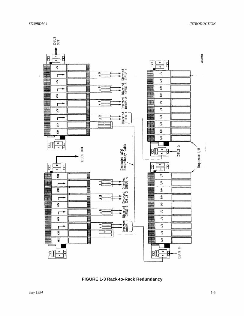
The BDM can support both module-to-module and rack-to-rack redundancy as illustrated in Figures 1-2 and1-3.
Each installed BDM requires a companion BDM Extended Transition Board when local I/O termination isemployed or BDM Transition Board when remote I/O termination is chosen. Both provide IOBUS A OUTand IOBUS B OUT 25-pin connectors for the connection of IOBUS extension cables. IOBUS A and Bterminal blocks are also provided to accommodate the connection of unterminated (without connector) IOBUScables.

INTRODUCTION SD39BDM-1
July 19941-2
The Bus Diverter Module contains no active circuitry; therefore, it has no protective cover. The module ismechanically keyed to prevent accidental installation in an active module's slot.
1.2 RELATED LITERATURE
The following literature should be available to complement the ACM installation.
SD39MODULRAC-1, APACS MODULRAC Installation Instruction
#

SD39BDM-1 INTRODUCTION
July 1994 1-3
FIGURE 1-1 Bus Diverter Module and Transition Boards

INTRODUCTION SD39BDM-1
July 19941-4
FIGURE 1-2 Typical BDM Architectures
SD39BDM-1 INTRODUCTION
July 1994 1-5
FIGURE 1-3 Rack-to-Rack Redundancy

SD39BDM-1 INSTALLATION
July 1994 2-1
2.0 INSTALLATION
This section describes the installation of the Bus Diverter Module (BDM), BDM Transition Boards, IOBUScables, and IOBUS Shunt Modules . Read this entire section before starting an installation.
IMPORTANT
A BDM installation should be in accordance with the National Electrical Code (NEC)and other applicable construction and electrical codes.
2.1 INSTALLATION CONSIDERATIONS
1. Install the MODULRAC and Local Termination Panel (for local termination only) in the MODULPACor cabinet where BDMs are to be installed. BDMs should not be installed in the MODULRAC at thistime; however, note the MODULRAC slots numbers for BDM installation.
Note that in determining a MODULRAC slot for a BDM:
• A BDM must be installed in a slot to the right of an ACM (higher slot number) and is paired with thatACM.
• I/O type modules may be placed between an ACM and BDM.
2. Select the needed transition board:
• BDM Extended Transition Board• BDM Transition Board
3. Determine whether redundant ACMs will be installed.
ACM hardware and software provides for module-to-module redundancy (also known as peer-to-peerredundancy) and rack-to-rack redundancy as described below. In particular, note the slot restrictions thatapply to module-to-module redundancy.
Module-to-Module Redundancy - Two ACMs can be mounted in adjacent odd-even (e.g., 1-2, 3-4, 5-6,7-8, 9-10) slots in a MODULRAC. I/O modules and the BDM are mounted in slots to the right of thesecond ACM (even slot). One ACM is operating, the other is in standby and can instantly assume controlshould a failure occur in the operating ACM. The ACMs communicate with each other over a dedicatedredundancy cable. See Figure 1-2: Module-to-Module Redundancy.
Rack-to-Rack Redundancy - Each ACM/BDM pair are mounted in separate MODULRACS whose IOBUSis diverted to separate MODULRACS containing duplicate I/O. One ACM-I/O system is operating, theother is in standby and can instantly assume control should a failure occur in the operating system. TheACMs communicate over a dedicated redundancy cable. See Figure 1-3.
4. Determine the needed end-to-end length of IOBUS A/B cables required to connect the diverted IOBUS(start of bus) to the last (end of bus) daisy chained MODULRAC. A maximum of three additionalMODULRACS housing thirty slaved I/O modules are permitted.
INSTALLATION SD39BDM-1
July 19942-2
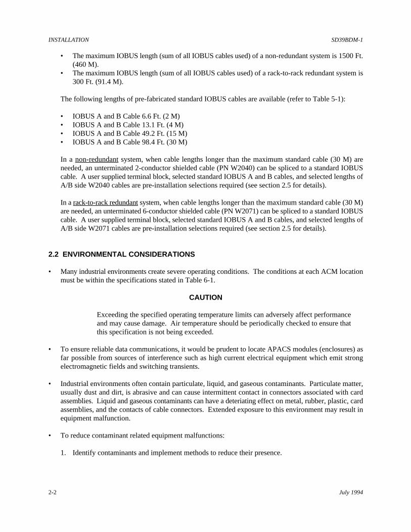
• The maximum IOBUS length (sum of all IOBUS cables used) of a non-redundant system is 1500 Ft.(460 M).
• The maximum IOBUS length (sum of all IOBUS cables used) of a rack-to-rack redundant system is300 Ft. (91.4 M).
The following lengths of pre-fabricated standard IOBUS cables are available (refer to Table 5-1):
• IOBUS A and B Cable 6.6 Ft. (2 M)• IOBUS A and B Cable 13.1 Ft. (4 M)• IOBUS A and B Cable 49.2 Ft. (15 M)• IOBUS A and B Cable 98.4 Ft. (30 M)
In a non-redundant system, when cable lengths longer than the maximum standard cable (30 M) areneeded, an unterminated 2-conductor shielded cable (PN W2040) can be spliced to a standard IOBUScable. A user supplied terminal block, selected standard IOBUS A and B cables, and selected lengths ofA/B side W2040 cables are pre-installation selections required (see section 2.5 for details).
In a rack-to-rack redundant system, when cable lengths longer than the maximum standard cable (30 M)are needed, an unterminated 6-conductor shielded cable (PN W2071) can be spliced to a standard IOBUScable. A user supplied terminal block, selected standard IOBUS A and B cables, and selected lengths ofA/B side W2071 cables are pre-installation selections required (see section 2.5 for details).
2.2 ENVIRONMENTAL CONSIDERATIONS
• Many industrial environments create severe operating conditions. The conditions at each ACM locationmust be within the specifications stated in Table 6-1.
CAUTION
Exceeding the specified operating temperature limits can adversely affect performanceand may cause damage. Air temperature should be periodically checked to ensure thatthis specification is not being exceeded.
• To ensure reliable data communications, it would be prudent to locate APACS modules (enclosures) asfar possible from sources of interference such as high current electrical equipment which emit strongelectromagnetic fields and switching transients.
• Industrial environments often contain particulate, liquid, and gaseous contaminants. Particulate matter,usually dust and dirt, is abrasive and can cause intermittent contact in connectors associated with cardassemblies. Liquid and gaseous contaminants can have a deteriating effect on metal, rubber, plastic, cardassemblies, and the contacts of cable connectors. Extended exposure to this environment may result inequipment malfunction.
• To reduce contaminant related equipment malfunctions:
1. Identify contaminants and implement methods to reduce their presence.

SD39BDM-1 INSTALLATION
July 1994 2-3
2. When cleaning equipment and surrounding area, especially the floor, either vacuum away all dust anddirt or use a dampened rag or mop.
3. Clean or replace all air conditioning filters, room air filters, and equipment filters regularly.
4. Inform personnel with access to APACS modules of the need for equipment cleanliness.
2.3 EQUIPMENT DELIVERY AND HANDLING
The following subsections provide information of interest to shipping, receiving, and warehouse personnel.
2.3.1 Predelivery Test
A BDM that will be installed by the user is fully tested and inspected to ensure proper operation. If the BDMis ordered factory installed in a MODULPAC or other enclosure, the BDM is tested as part of the APACSsystem and inspected to ensure proper operation.
2.3.2 Factory Shipment
BDMs to be installed by the user are placed in protective bags and packaged for shipment. Accessories arepackaged separately.
If the BDM is ordered factory installed in a MODULPAC or other enclosure, the enclosure is bolted to a palletand wrapped for protection during shipment.
2.3.3 Receipt of Shipment
All cartons should be inspected at the time of their delivery for possible external damage. Any visible damageshould be immediately recorded on the carrier's copy of the delivery slip.
Each carton should be carefully unpacked and its contents checked against the enclosed packing list. At thesame time, each item should be inspected for hidden damage that may or may not have been accompanied byexterior carton damage.
If it is found that some items have been damaged or are missing, notify Moore Products Co. immediately andprovide full details. In addition, damages must be reported to the carrier with a request for their on-siteinspection of the damaged item and its shipping carton.
2.3.4 Return of Shipment
To return equipment: Call the Service Department at (215) 646-7400, ext. 4RMA (4762) weekdays between8:00 a.m. and 4:45 p.m. Eastern Time to obtain an RMA number. Mark the RMA number prominently on theoutside of the return shipment.

INSTALLATION SD39BDM-1
July 19942-4
When calling for an RMA number, provide the reason for the return. If returning equipment for repair, failureinformation (e.g., error code, failure symptom, installation environment) will be requested. Supply a purchaseorder number for nonwarranty repairs.
A Material Safety Data Sheet (MSDS) must be included with each item being returned that was stored or usedanywhere hazardous materials were present.
Package assembly in original shipping materials; otherwise, package it for safe shipment or contact the factoryfor shipping recommendations. A module must be placed in a protective bag prior to packaging.
2.3.5 Equipment Handling
The BDM contains no active circuitry and may be safely handled without undertaking special ESD(electrostatic discharge) handling procedures. Be careful no to damage the connector pins on the back of themodule. Handle the module carefully and do not subject it to excessive shock or vibration.
2.3.6 Equipment Storage
The environmental storage temperature and humidity parameters of Table 6.1 must be met for storage of aBDM.
2.4 MECHANICAL INSTALLATION
This section describes installation of transition boards, module, and MODULRAC keying.
2.4.1 BDM Transition or Extended Transition Board Installation
Mount an ACM Extended Transition Board (Figure 1-1) at the MODULRAC slot location of its companionACM when local I/O termination is employed. A Local Termination Panel must be installed.
Mount an ACM Transition Board (Figure 1-1) at that MODULRAC slot when marshalled I/O termination isemployed. A Local Termination Panel is not installed with marshalled I/O termination.
Refer to Figure 2-1 and the following mounting instructions:
1. Consult user MODULRAC documentation and note the slot location assigned to the ACM(s).
2. Note the following on a MODULRAC and on the transition board:
• On the MODULRAC, locate and identify the extruded spacer to which the lower edge of thebackplane is mounted. Note that the bottom of the extruded spacer is grooved. The top edge of thetransition board will rest in this groove.

SD39BDM-1 INSTALLATION
July 1994 2-5
FIGURE 2-1 BDM Transition Board and Extended Transition Board Mounting

INSTALLATION SD39BDM-1
July 19942-6
• Identify ten alignment pins located below the MODULRAC frame that span the width of theMODULRAC. The left-most pin corresponds to MODULRAC slot #1. One of these pins will engagea hole located on the termination board above the MOORE logo.
• A transition board's captive mounting screws can be seen projecting from the bottom of the plasticextrusion panel.
3. Mount the transition board at its assigned location as follows:
1) Angle the top edge of the board toward the backplane's extruded spacer and insert the tip of the boardin the spacer's groove.
2) Slide the board in the groove until it is vertically and horizontally aligned with the appropriate pin (slot#).
3) Carefully lower the transition board and engage the alignment pin with the extrusion and board pinmounting holes. Firmly push down to seat the board on the pin. When the board is properly seated,the pin will be flush with, or project slightly above the board's surface.
4) Tighten the captive mounting screws which are aligned with their respective mounting holes.
2.4.2 BDM Installation
Modules are shipped individually packaged in protective, sealed, static shielding bags. Refer to section 2.3.5for module handling considerations and section 2.4.2.2 for installation of the module.
Each MODULRAC slot and each module must be keyed to prevent accidental installation of a module intoan incompatible slot which may impair system performance. Keying is highly recommended.
• Modules are keyed at the factory. The keying pattern is unique to each module type (e.g. ACM, ICM,PSM). See Figure 2-2.
• A factory assembled MODULRAC is keyed at the factory. A user assembled MODULRAC is keyed bythe user according to the module type assigned to each slot. This keying pattern complements the module'skeying pattern. Stop plugs are supplied with the MODULRAC.
• When adding a module to a MODULRAC, key the MODULRAC slot (see section 2.4.2.1).
2.4.2.1 MODULRAC Mechanical Keying
1. Get the MODULRAC Keying Kit supplied with the MODULRAC.
2. Refer to Figure 2-2 and note the MODULRAC keying pattern. Also, locate the MODULRAC top andbottom rails.
3. Press the stop plugs into the holes identified by the solid dots.

SD39BDM-1 INSTALLATION
July 1994 2-7
FIGURE 2-2 Module Keying Assignment and Installation

INSTALLATION SD39BDM-1
July 19942-8
2.4.2.2 Module Installation
1. Refer to user documentation for correct module slot number and location of BDM transition board.
2. Remove the BDM from its static shielding bag and ensure that the module is keyed. Also, check theMODULRAC slot to be sure it is keyed.
3. Insert the module in the assigned MODULRAC slot. Firmly seat the module in the backplane andtransition board connectors. A properly seated module will have the rear of its bezel flush against theMODULRAC's front rails.
A keyed module that is not matched to a keyed slot will not engage the backplane or transition boardconnectors or seat flush against the MODULRAC's front rails.
4. Pull open the bezel's pivoting top and bottom handles to expose the slotted captive mounting screws andsecure the module to the top and bottom rails. Close the bezel's handles when finished.
IMPORTANT
Do not use the captive mounting screws to seat the module. Damage to the bezel canresult.
2.5 ELECTRICAL INSTALLATION
This section describes installation of IOBUS cables and IOBUS Shunt Modules.
2.5.1 Cable Connections
Section 2.5.1.1 describes connection of standard length IOBUS cables. Section 2.5.1.2 describes connectionof W2040 IOBUS cable and section 2.5.1.3 the connection of W2071 IOBUS cable.
2.5.1.1 Standard IOBUS Cables
Refer to Figure 2-3 and connect standard IOBUS A and B cables as follows:
1. Consult user documentation and identify the MODULRAC(s) and BDM slots where BDM transitionboards are installed. Note the standard length IOBUS cable associated with each BDM.
2. Connect one end of each of the pairs of standard IOBUS cables to their following respective connectors:
• Connectors J2 IOBUS A OUT and J3 IOBUS B OUT on a BDM Transition Board.
• Connectors J19 IOBUS A OUT and P24 IOBUS B OUT on the MODULRAC backplane panel.These connectors are the standard IOBUS exit point from theMODULRAC. When used, theyeliminate the need of a BDM and transition board (see Figure 1-2).

SD39BDM-1 INSTALLATION
July 1994 2-9
FIGURE 2-3 Standard IOBUS A and B Cables

INSTALLATION SD39BDM-1
July 19942-10
3. Refer to the MODULRAC (SD39MODULRAC-1) and/or IOBUS repeater documents for details onconnecting the opposite ends of the cables.
2.5.1.2 W2040 IOBUS Cable
The following procedure describes a non-redundant system connection of W2040 cable between a BDMTransition Board and its associated remote mounted MODULRAC. This procedure is used when an IOBUScable length exceeding the maximum standard length of 30 meters and less than 457 M (1500 ft) is needed.
1. Preliminary Preparation
1) Refer to Figure 2-4 and note that a user supplied terminal block is required to wire (splice) the IOBUSA and B W2040 cables to the cut (unterminated) ends of standard IOBUS A and B cables.
Select a DIN rail mounted style terminal block. The terminal block must be able to accommodate wiresizes ranging from 16 to 28 AWG.
2) In the associated MODULRAC's enclosure, select a mounting location for the terminal block.
3) Measure the length of cable required to connect from the terminal block to the IOBUS A IN (J18) andIOBUS B IN (P21) connectors on the MODULRAC backplane. Refer to Table 5-1 and select a lengthof IOBUS A and B cables equal to or greater than the measured length.
4) Route the IOBUS A and B W2040 cables between the BDM Transition Board and the associated I/OMODULRAC. Tag both ends of each cable as being either IOBUS A or IOBUS B. Pull the ends ofthe cables into their respective enclosures.
2. Mount the user-supplied terminal block at its selected location in the enclosure.
3. Modify the selected IOBUS A and B cables.
1) Cut off the DB25 (25 pins) male connector from the IOBUS A cable and the DB25 (25 pins) femaleconnector from the IOBUS B cable.
2) Tag each unterminated cable end as being either IOBUS A or IOBUS B.
4. Connect both modified IOBUS cables to the MODULRAC.
• Connect the DB15 male connector of modified IOBUS A cable to the IOBUS A IN connector J18 onthe MODULRAC.
• Connect the DB15 female connector of modified IOBUS B cable to the IOBUS A IN connector P21on the MODULRAC.
5. Route both cables to the terminal block. Provide strain relief of the cable near the termimal block. 6. Identify the color code of the cable wires to be connected in Table 2-1. Refer to Figure 2-5 to prepare the
cable wires and shield for connection to the terminal block.

SD39BDM-1 INSTALLATION
July 1994 2-11
FIGURE 2-4 W2040 Cable Splicing

INSTALLATION SD39BDM-1
July 19942-12
TABLE 2-1 Standard IOBUS Cable Wire Identification
DB15 Connector Pin No. Wire Color Code Nomenclature
1 Orange\White Stripe IOBUS (+)
2 White\Orange Stripe IOBUS (-)
3 White\Blue Stripe MRET (Redundancy Signal)
4 White\Green Stripe MOK (Redundancy Signal)
5 Blue\White Stripe MEN (Redundancy Signal)
6 Green\White Stripe OKIN (Redundancy Signal)
7. Refer to Figure 2-4 and Table 2-1 and connect the shield wires and all cable conductors to the terminalblock.
8. Refer to Figure 2-6 and prepare the shield and cable ends of the IOBUS A/B W2040 cables. Providestrain relief of the cables near the terminal block. Refer to Figure 2-4 and connect the shields and blueIOBUS (+) and white IOBUS (-) cable wires.
9. At the BDM Transition Board location (slot number), refer to Figure 2-6 and prepare (strip) theunconnected cable ends of the IOBUS A/B W2040 cables. Provide strain relief of the cables near thetransition board. Refer to Figure 2-4 and connect only the blue IOBUS (+) and white IOBUS (-) cablewires to the transition board's IOBUS terminal block. Do not connect the shield.

SD39BDM-1 INSTALLATION
July 1994 2-13
FIGURE 2-5 Modified Standard IOBUS Cable Preparation

INSTALLATION SD39BDM-1
July 19942-14
FIGURE 2-6 W2040 Cable Preparation

SD39BDM-1 INSTALLATION
July 1994 2-15
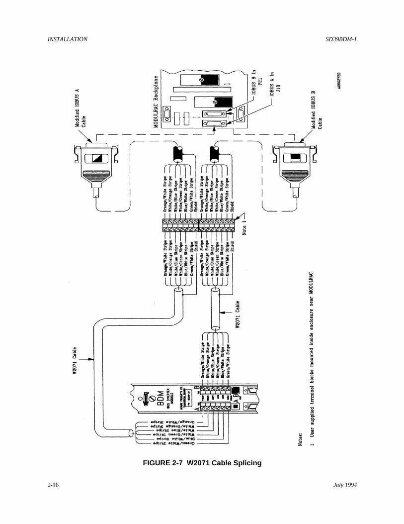
2.5.1.3 W2071 IOBUS Cable
The following procedure describes a redundant system connection of W2071 cable between a BDM TransitionBoard and its associated remote mounted MODULRAC. This procedure is used when an IOBUS cable lengthexceeding the maximum standard length of 30 meters and less than 91 M (300 ft.) is needed.
1. Preliminary Preparation
1) Refer to Figure 2-7 and note that a user supplied terminal block is required to wire (splice) the IOBUSA and B W2071 cables to the cut (unterminated) ends of standard IOBUS A and B cables. Select a DIN rail mounted style terminal block. The terminal block must be able to accommodate wiresizes ranging from 16 to 28 AWG.
2) In the associated MODULRAC's enclosure, select a mounting location for the terminal block.
3) Measure the length of cable required to connect from the terminal block to the IOBUS A IN (J18) andIOBUS B IN (P21) connectors on the MODULRAC backplane. Refer to Table 5-1 and select a lengthof IOBUS A and B cables equal to or greater than the measured length.
4) Route the IOBUS A and B W2071 cables between the BDM Transition Board and the associated I/OMODULRAC. Tag both ends of each cable as being either IOBUS A or IOBUS B. Pull the ends ofthe cables into their respective enclosures.
2. Mount the user supplied terminal block at its selected location in the enclosure.
3. Modify the selected IOBUS A and B cables.
1) Cut off the DB25 (25 pins) male connector from the IOBUS A cable and the DB25 (25 pins) femaleconnector from the IOBUS B cable.
2) Tag each unterminated cable end as being either IOBUS A or IOBUS B.
4. Connect both modified IOBUS cables to the MODULRAC.
1) Connect the DB15 male connector of modified IOBUS A cable to the IOBUS A IN connector J18 onthe MODULRAC.
2) Connect the DB15 female connector of modified IOBUS B cable to the IOBUS A IN connector P21on the MODULRAC.
5. Route both cables to the terminal block. Provide strain relief of the cable near the termimal block. 6. Refer to Figure 2-5 to prepare the cable wires and shield for connection to the terminal block.
7. Refer to Figure 2-7 and Table 2-1 and connect the shield and all cable wires to the terminal block.
INSTALLATION SD39BDM-1
July 19942-16
FIGURE 2-7 W2071 Cable Splicing

SD39BDM-1 INSTALLATION
July 1994 2-17
FIGURE 2-8 W2071 Cable Preparation

INSTALLATION SD39BDM-1
July 19942-18
8. Refer to Figure 2-8 to prepare the cable wires and shields of the IOBUS A/B W2071 cables. Providestrain relief of the cables near the terminal block. Cable conductor color code matches that of the standardIOBUS cable. Refer to Figure 2-7 and Table 2-1 and connect all wires including the shields to theterminal block.
9. At the BDM Transition Board location (slot number), prepare the cable wires per Figure 2-8. Providestrain relief of the cables near the transition board. Refer to Figure 2-7 and Table 2-1 and connect all cablewires to the transition board's IOBUS terminal block. Do not connect the shield.
2.5.2 IOBUS Shunt Module Installation
A description of the function of the IOBUS Shunt Modules in configuring the IOBUS is provided in section4. Review this section before continuing with shunt module installation.
Refer to Figure 2-9 for an illustration of the IOBUS Shunt Modules and their location on the MODULRACbackplane.
Install the MODULRAC and BDM IOBUS Shunt Modules as follows:
1. Consult user documention and drawings to determine the IOBUS configuration in all involvedMODULRACS and slot locations of their pairs of ACMs and BDMs. The MODULRAC Instruction listedin section 1.2 is required to complete the installation.
2. Refer to the following rules to install the needed MODULRAC and BDM IOBUS Shunt Modules:
1) Non-Redundant System
• One BDM Shunt Module is supplied with each BDM. Eleven MODULRAC Shunt Modules aresupplied with each MODULRAC.
• Install a BDM Shunt Module (BDM TERMINATE position) at the break point location (W1 toW11) immediately following the slot of each installed BDM.
IMPORTANT
A MODULRAC Shunt Module cannot be installed at a break pointfollowing an installed BDM. The preceeding diverted IOBUS will notoperate properly. See Detail A of Figure 4-2, Note 5.
• If I/O modules occupy continuous slots between the associated ACM and BDM, installMODULRAC Shunt Modules in the IOBUS CONTINUE position in the break point locationsimmediately following the slot of the ACM and immediately following the slots of each installedI/O Module.

SD39BDM-1 INSTALLATION
July 1994 2-19
FIGURE 2-9 IOBUS Shunt Module Locations

INSTALLATION SD39BDM-1
July 19942-20
• If I/O modules are not installed before the IOBUS is diverted, install MODULRAC ShuntModules in the IOBUS CONTINUE position in the break point locations immediately followingthe slot of the ACM and immediately following the slots of each installed BCM.
NOTE
The diverted A and B IOBUS are carried by IOBUS extension cables to the remoteMODULRACS housing the I/O modules and must be configured and terminated at that end.To configure and terminate the IOBUS, refer to the MODULRAC document listed in section1.2 of this Instruction.
2) Module-to-Module Redundancy
• One IOBUS BDM Shunt Module is supplied with each BDM. Eleven MODULRAC Shunt Modulesare supplied with each MODULRAC.
• Redundant ACMs must be mounted in adjacent odd-even slots.
• Install a BDM Shunt Module (BDM TERMINATE) at the break point location (W1 to W11)immediately following the slot of the each installed BDM.
IMPORTANT
A MODULRAC Shunt Module cannot be installed at a break pointfollowing an installed BDM. The preceeding diverted IOBUS will notoperate properly. See Detail A of Figure 4-2, Note 5.
• Install a MODULRAC Shunt Modules in the IOBUS CONTINUE position in the break point locationimmediately following the slot of the first ACM and immediately following the slot of the secondACM.
• If I/O modules occupy slots immediately to the right of the redundant (second) ACM, installMODULRAC Shunt Modules in the IOBUS CONTINUE position in the break point locationsimmediately following the slots of each installed I/O Module.
NOTE
The diverted A and B IOBUS are carried by IOBUS extension cables to the remoteMODULRACS housing the I/O modules and must be configured and terminated at that end.To configure and terminate the IOBUS, refer to the MODULRAC document listed in section1.2 of this Instruction.
3) Rack-to-Rack Redundancy
• One IOBUS BDM Shunt Module is supplied with each BDM. Eleven MODULRAC Shunt Modulesare supplied with each MODULRAC.
• Redundant ACMs must be mounted in separate MODULRACS in identical slot numbers.

SD39BDM-1 INSTALLATION
July 1994 2-21
• Install a BDM Shunt Module (BDM TERMINATE) at the break point location (W1 to W11)immediately following the slot of the each installed BDM.
IMPORTANT
A MODULRAC Shunt Module cannot be installed at a break pointfollowing an installed BDM. The preceeding diverted IOBUS will notoperate properly. See Detail A of Figure 4-2, Note 5.
• If I/O modules occupy continuous slots between the associated ACM and BDM, install MODULRACShunt Modules in the IOBUS CONTINUE position in the break point locations immediately followingthe slot of the ACM and immediately following the slots of each installed I/O Module.
• If I/O modules are not installed before the IOBUS is diverted, then Bus Continuation Modules(BCMs) must occupy the slots between the ACM and BDM. Install MODULRAC Shunt Modulesin the IOBUS CONTINUE position in the break point locations immediately following the slot of theACM and immediately following the slots of each installed BCM.
NOTE
The diverted A and B IOBUS are carried by IOBUS extension cables to the remoteMODULRACS housing the I/O modules and must be configured and terminated at that end.To configure and terminate the IOBUS, refer to the MODULRAC document listed in section1.2 of this Instruction.
#

SD39BDM-1 MAINTENANCE
July 1994 3-1
3.0 MAINTENANCE
The BDM and its associated transition board require minimal maintenance. Some routine maintenance isrecommended in the form of a visual inspection and a possible cleaning.
3.1 TOOL AND EQUIPMENT REQUIREMENTS
The following tools and equipment are necessary for servicing:
• Common electronic servicing hand tools• Digital Multimeter (DMM), Ohmmeter function
3.2 PREVENTIVE MAINTENANCE
The following subsections are the recommended preventive maintenance procedures.
3.2.1 Visual Inspection
The BDM and its associated transition board should be subjected to a periodic visual inspection. Thefrequency of inspection will depend on the severity of the operating environment. The primary aim of the inspection is to reveal an excessive accumulation of dust, dirt, or other foreignmaterial adhering to the transition board. Accumulation of dirt and dust or corrosive material may causethe IOBUS connector contacts to become intermittent or fail. A BDM installed in a cabinet complyingwith the NEMA 12/IP55 specification need not be inspected for cleanliness. Refer to section 3.2.2 forcleaning instructions.
3.2.2 Cleaning
Cleaning a module involves brushing or vacuuming the protective covers to restore cooling efficiency thatmay have been degraded by accumulated dust.
Cleaning a transition board involves careful brushing and vacuuming to remove accumulated dust and dirtharboring chemical particulate that may accelerate connector contact corrosion.
3.3 TROUBLESHOOTING
Fault analysis focuses on identifying a failure as annunciated by the operator interface, typicallyMYCROADVANTAGE™. If the MYCROADVANTAGE alarm blocks have been configured, IOBUSand redundancy errors will be reported. The error code along with a description of the error and correctiveaction to be taken by the user can be accessed by the operator.
Failure annunciation and fault analysis is also available within 4-mation Release 2 software (seeConfiguration Guide CG39-5).

MAINTENANCE SD39BDM-1
July 19943-2
When a fault is identified, correct the fault as indicated by the software.
Refer to section 3.3.1 for troubleshooting information specific to the BDM.
3.3.1 BDM Troubleshooting
The BDM is classified as an empty module and, therefore, does not contain active circuitry. However, itcontains an IOBUS Diverter Board whose function is explained in section 4.
If a BDM is removed or not seated properly in its slot, IOBUS communications between the ACM and allI/O modules on the diverted IOBUS would be interrupted. After detecting the communications failure,each I/O module will disable its I/O. This event would be annunciated in the configured alarm blocks ofthe operator interface.
It is highly unlikely that a continuity break would occur in any of the diverted IOBUS signal lines whosepaths are traced as follows:
From BDM P1-to-IOBUS Diverter Board-to-BDM P2-to-BDM Transition Board J1-to-BDM TransitionBoard J2/TB2 and J3/TB3.
An Ohmmeter and the composite schematic in Figure 4-1 can be used to verify continuity of the signalpath.
The BDM does not contain a cover plate, therefore, when it is removed from the rack, connectors P1 andP2 and the IOBUS Diverter Board are exposed for servicing.
Refer to Figure 3-1 for the pin orientation of the BDM's rear P1 and P2 connectors.

SD39BDM-1 MAINTENANCE
July 1994 3-3
P1/P2
C A 1 $ $ $ $ $ $ $ $ $ $ $ $ $ $ $ $ $ $ $ $ $ $ $ $ $ $ $ $ $ $ $ $ $ $ $ $ $ $ $ $ $ $ $ $ $ $ $ $ $ $ $ $ $ $ $ $ $ $ $ $ $ $ 32$ $
FIGURE 3-1 P1/P2 Pin Orientation
3.4 ASSEMBLY REPLACEMENT
The following subsections provide assembly removal and replacement procedures.
3.4.1 BDM Removal/Replacement
The MODULRAC may be powered while removing or installing a module.
Remove the BDM as follows:
1. Determine the effect the removal of a BDM will have on the process, and if necessary, idle or shutdown the process. The removal of a BDM can cause the following action:
Rack-to-rack Redundant System: Removal of the BDM associated with the active ACM will cause aredundancy switchover to the backup system.
Non-Redundant System: Removal of the BDM will cause the outputs of the associated I/O modules torevert to their default states.

MAINTENANCE SD39BDM-1
July 19943-4
2. As shown in Figure 2-2, pull open bezel's pivoted top and bottom handles to expose the module'sslotted captive mounting screws. Loosen the screws.
3. Grasp the top and bottom handles and pull the module from the card cage. Place the module in aprotective bag and package for return (see section 2.3.4 for instructions).
Replace the BDM as follows:
1. Remove the replacement BDM from its protective bag. It may be safely handled as it contains noactive circuitry. Ensure the module is correctly keyed.
2. Insert the module in its MODULRAC slot. Firmly seat the module in the backplane and transitionboard connectors. A properly seated module will have the rear of its bezel flush against theMODULRAC Housing rails.
A keyed module that is not matched to a slot will not engage the backplane or termination boardconnectors or seat flush against the MODULRAC Housing's front rails.
3. As shown in Figure 2-2, pull open bezel's pivoted top and bottom handles to expose the module'sslotted captive mounting screws and secure the module to the top and bottom rails. Close the bezel'shandles when finished.
IMPORTANT
Do not use the captive mounting screws to seat the module. Damage to the bezel canresult.
3.4.2 BDM Transition Board Removal/Replacement
Refer to Figure 2-1 and the following removal procedure:
1. Remove the associated BDM from its slot in the MODULRAC; see section 3.4.1. Place the module ina bag for protection.
2. Remove IOBUS A and B cables from the transition board.
IMPORTANT
All cables should be labeled for correct reconnection.
3. Loosen the transition board's captive mounting screws. Gently lift the bottom of the board in an arcuntil the board is free of its alignment pin located above the "MOORE" logo. Pull the top of thetransition board from the grooved backplane spacer and lift it from the MODULRAC.
Refer to Figure 2-1 and the following replacement procedure:
1. Refer to section 2.4.1 and install the replacement transition board.

SD39BDM-1 MAINTENANCE
July 1994 3-5
2. Reconnect IOBUS A and B cables.
3. Install the BDM. See section 3.4.1.
3.5 SPARE AND REPLACEMENT PARTS
One spare Bus Diverter Module and BDM Shunt Module (PN 16256-61) should be stocked. Spares canbe ordered from one of the addresses in the Warranty statement or through a local Moore Products Co.representative.
Assembly part numbers are stated in section 1 and printed on most modules and associated hardware.
When ordering, provide the model number from the module's nameplate to be replaced or spared. Apurchase order number should also be included.
The Bus Diverter Module contains two nameplate labels: a large label, shown below, located on thetracking plate (left side of BDM in Figure 1-1), and a small label inside the bezel battery compartment. Both labels contain the module's Model Designation, Part Number, and Serial Number.
MODEL 39BDMNAN AMPS P/N 16256-1
VOLTS S/N xxxxxx
3.6 MAINTENANCE RECORDS
An accurate record keeping system for tracking maintenance operations should be established and kept upto date. Data extracted from the record may serve as a base for ordering maintenance supplies, includingspare parts. The record may also be useful as a troubleshooting tool. In addition, maintenance recordsmay be required to provide documentary information in association with a service contract. It is suggestedthat the following information be recorded:
1. Date of service incident2. Name or initials of service person3. Brief description of incident symptoms and repairs performed4. Replacement part or assembly number5. Software compatibility code of original part6. Software code of replacement part7. Serial number of original part8. Serial number of replacement part9. Issue number of original circuit module10. Issue number of replacement circuit module 11. Date of completion #

SD39BDM-1 CIRCUIT DESCRIPTION
July 1994 4-1
4.0 CIRCUIT DESCRIPTION
This section provides the following information:
• A composite schematic of the BDM Diverter Board and BDM Transition Board.• The use of IOBUS Shunt Modules in configuring the IOBUS.• IOBUS signals and their significance.
4.1 IOBUS DIVERTER BOARD AND BDM TRANSITION BOARD
The Bus Diverter Module contains no active circuitry. It contains an IOBUS Diverter Board, a smallprinted circuit board that conducts the differential A and B IOBUS and redundancy signals. As shown inFigure 4-1, these signals are accessed from the IOBUS on the MODULRAC's backplane via the BDM'srear P1 connector.
The signals are conducted across the Diverter Board to the BDM's rear P2 connector which mates with theJ1 connector on the BDM Transition Board. They are then routed by the board to the IOBUS A and BOUT connectors J2 and J3 and A and B terminal blocks. These connectors (J2/J3) are identical to theIOBUS A and B OUT connectors J19 and P24 located on the right side of the MODULRAC's backplaneand provide for the connection of standard length IOBUS cables.
Terminal blocks A and B on the BDM Transition Board, provide for the connection of unterminatedW2040 and W2071 IOBUS cables when cable lengths exceeding the maximum available standard IOBUScable are required.
4.2 IOBUS CONFIGURATION
In order to divert the A and B IOBUS from a MODULRAC, each must be configured to do so by using aBus Diverter Module (BDM) in conjunction with two types of shunt modules; a MODULRAC ShuntModule and a BDM Shunt Module. Figure 4-2 illustrates the printed circuit (PC) track of the A and BIOBUS across the MODULRAC backplane and the use of each type of shunt.
As shown in Figure 4-2, the differential A and B IOBUS and their redundancy signals are interrupted bybreak points at eleven locations designated as W1 to W11. MODULRAC Shunt Modules and BDMShunt Modules are installed at these break points to either continue or terminate the IOBUS. If a shuntmodule is not installed at any break point, the IOBUS and redundancy signals are open circuited at thatlocation.
MODULRAC Shunt Modules are supplied with each MODULRAC and provide dual functions. Asshown in Detail A in Figure 4-2, when placed in the IOBUS CONTINUE position at break points W11,W1, W3, and W5, the differential A and B IOBUS and their redundancy signals are jumpered across thebreak point.

CIRCUIT DESCRIPTION SD39BDM-1
July 19944-2
FIGURE 4-1 BDM Diverter Board and BDM Transition Board Schematic

SD39BDM-1 CIRCUIT DESCRIPTION
July 1994 4-3
FIGURE 4-2 IOBUS Configuration with IOBUS Shunt Modules

CIRCUIT DESCRIPTION SD39BDM-1
July 19944-4
When placed in the IOBUS TERMINATE position, a MODULRAC Shunt Module is used to providetermination at the end of one IOBUS and termination at the beginning of the following IOBUS. Detail Aof Figure 4-2 implies that an IOBUS has been extended from a preceding MODULRAC (not shown) andis terminated at break point W2 following the I/O modules installed in slots 1 and 2. Note that theMODULRAC Shunt (IOBUS TERMINATE) terminates the IOBUS both to the left and right of W2. Theleft side terminates the end of the incoming IOBUS while the right side terminates the beginning ofdiverted IOBUS 1. This example illustrates the legitimate use of the MODULRAC Shunt Module toterminate the IOBUS.
The MODULRAC Shunt Module can be used illegally to terminate the IOBUS. As shown in Detail A ofFigure 4-2, when placed in the IOBUS TERMINATE position at break point W6, it terminates divertedIOBUS 1 a second time. The beginning of diverted IOBUS 1 is terminated at break point W4 with a BDMShunt Module (BDM TERMINATE). The second termination in effect terminates the end of IOBUS 1before it is diverted. This is illegal and causes improper operation of diverted IOBUS 1. Note thefollowing restriction on the use of the MODULRAC IOBUS Shunt Module.
IMPORTANT
A MODULRAC Shunt Module cannot be installed in the IOBUS TERMINATE positionat a break point following an installed BDM. The preceding IOBUS will be terminatedtwice before it is diverted and will not operate properly. Only a BDM Shunt Module canfollow an installed BDM.
A BDM Shunt Module is supplied with each BDM. This shunt can only be installed in the BDMTERMINATE position. As shown in Detail A in Figure 4-2, when installed at break point W4, the shuntterminates the IOBUS to the right of the break point and leaves the IOBUS to the left of W4 unterminated. A BDM Shunt Module is always installed following an installed BDM.
4.3 IOBUS SIGNALS
The diverted IOBUS comprises the following signals:
• IOB A +• IOB A -• IOB B +• IOB B -• MRET• MOK• MEN• OKIN
The following discusses the significance of these signals.
• IOB A+/B+ and IOB A-/B-: These differential pairs carry the communications between the ACM andits I/O slaves. They are bused across the MODULRAC backplane through each MODULRAC IOBUSShunt Module (IOBUS CONTINUE position) and connects to the IOBUS A/B IN/OUT connectorslocated on each end of the MODULRAC backplane.

SD39BDM-1 CIRCUIT DESCRIPTION
July 1994 4-5
• MEN (Master Enable): This redundancy signal line is bused across the backplane through theMODULRAC IOBUS Shunt Modules (IOBUS CONTINUE) and connects to the IOBUS A/BIN/OUT connectors. The line is broken when either a MODULRAC IOBUS Shunt or BDM Shunt isin the "terminate" position. The ACM sources this signal with an FET tied to +5V. I/O modules placean opto-coupler diode across this line and the MRET line. If the MEN signal causes the opto-couplerto conduct, the module is enabled and the outputs can be energized.
• MRET (Master Enable Return): This redundancy signal line is bused across the backplane through theMODULRAC IOBUS Shunt Modules (IOBUS CONTINUE) and connects to the IOBUS A/BIN/OUT connectors. The line is broken when either a MODULRAC IOBUS Shunt or BDM Shunt isin the "terminate" position. The line is tied to common in the originating ACM and provides a"ground-loop free" return for each I/O module.
• OKIN (and OKOUT): This redundancy signal line is daisy chained across the backplane through theMODULRAC IOBUS Shunt Modules (IOBUS CONTINUE) and connects to the IOBUS A/BIN/OUT connectors. Each module has an opto-isolator transistor that connects the OKIN and OKOUTlines, which form one long continuity loop. The signal (1.4 mA constant current source) originates inthe ACM and loops back onto the MOK line at the right-hand termination point of the IOBUS. TheOKIN/OUT signal is jumpered to the MOK line by a MODULRAC IOBUS Shunt Module in the"terminate" position. The ACM reads the state of MOK to determine if any of the modules on theIOBUS are not OK.
• MOK (Master OK): A redundancy signal loop-back line which gives the result of the OK continuitystring. The line is bused across the backplane through the MODULRAC IOBUS Shunt Modules(IOBUS CONTINUE) and connects to the IOBUS A/B IN/OUT connectors. The line is broken whena BDM Shunt is in the "terminate" position. The line is broken and jumpered to the OKOUTredundancy line when a MODULRAC IOBUS Shunt Module is in the "terminate" position. Whenthis line is open, the ACM is signaled that the OK continuity string is NOT OK.
Redundancy signals are functional in rack-to-rack redundant systems and are the factors used by eachACM in determining if a switchover to the redundant system should occur.
Redundancy signals are not applicable to non-redundant systems.
#
SD39BDM-1 MODEL DESIGNATION
July 1994 5-1
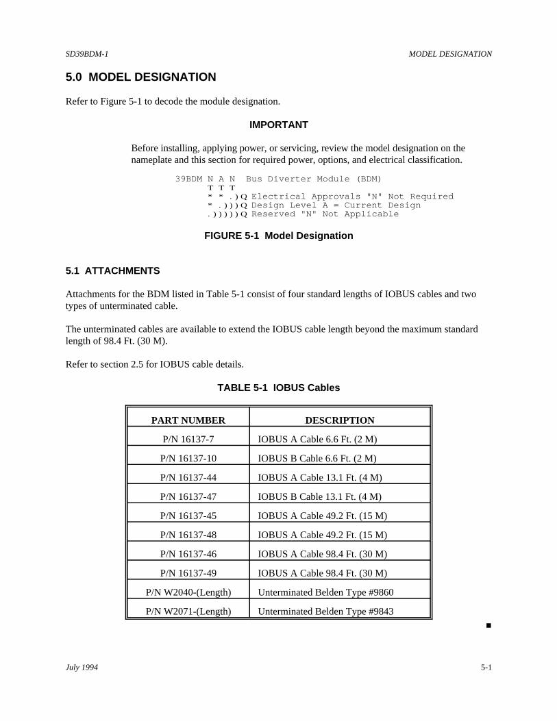
5.0 MODEL DESIGNATION
Refer to Figure 5-1 to decode the module designation.
IMPORTANT
Before installing, applying power, or servicing, review the model designation on thenameplate and this section for required power, options, and electrical classification.
39BDM N A N Bus Diverter Module (BDM) T T T * * .)Q Electrical Approvals "N" Not Required * .)))Q Design Level A = Current Design .)))))Q Reserved "N" Not Applicable
FIGURE 5-1 Model Designation
5.1 ATTACHMENTS
Attachments for the BDM listed in Table 5-1 consist of four standard lengths of IOBUS cables and twotypes of unterminated cable.
The unterminated cables are available to extend the IOBUS cable length beyond the maximum standardlength of 98.4 Ft. (30 M).
Refer to section 2.5 for IOBUS cable details.
TABLE 5-1 IOBUS Cables
PART NUMBER DESCRIPTION
P/N 16137-7 IOBUS A Cable 6.6 Ft. (2 M)
P/N 16137-10 IOBUS B Cable 6.6 Ft. (2 M)
P/N 16137-44 IOBUS A Cable 13.1 Ft. (4 M)
P/N 16137-47 IOBUS B Cable 13.1 Ft. (4 M)
P/N 16137-45 IOBUS A Cable 49.2 Ft. (15 M)
P/N 16137-48 IOBUS A Cable 49.2 Ft. (15 M)
P/N 16137-46 IOBUS A Cable 98.4 Ft. (30 M)
P/N 16137-49 IOBUS A Cable 98.4 Ft. (30 M)
P/N W2040-(Length) Unterminated Belden Type #9860
P/N W2071-(Length) Unterminated Belden Type #9843
#

SD39BDM-1 SPECIFICATIONS
July 1994 6-1
6.0 SPECIFICATIONS
This section lists environmental specifications for model 39BDMNAN.
6.1 ENVIRONMENTAL SPECIFICATIONS
Table 6-1 lists the BDM environmental specifications.
TABLE 6-1 BDM Environmental Specifications
CATEGORY SPECIFICATION DATA
Temperature Operating Temperature 0 to 60EC (32 to 140EF), and measured 0.25" below rack Humidity
Operating Humdiity 5 to 95%, Non-condensing
Maximum Mositure Limits 0.028 lb.water/lb.air
Storage Temperature Temperature -20 to 85EC (-4 to 185EF) and Humidity
Humidity 0 to 100%, condensing
Enclosure External External Temperature -20 to 50EC (-4 to 122EF) Temperature and Humidity External Humidity 0 to 100%, condensing
6.2 ELECTRICAL CLASSIFICATION
Contact Moore Products Co. for a list of pending approvals.
IMPORTANT
Certifications pending. Before installing, applying power to, or servicing anAPACS System, see each module's nameplate for electrical classification.
#

WARRANTY
The Company warrants all equipment manufactured by it and bearing its nameplate, and all repairs madeby it, to be free from defects in material and workmanship under normal use and service. If any part of theequipment herein described, and sold by the Company, proves to be defective in material or workmanshipand if such part is within twelve months from date of shipment from the Company's factory, returned tosuch factory, transportation charges prepaid, and if the same is found by the Company to be defective inmaterial or workmanship, it will be replaced or repaired, free of charge, f.o.b. Company's factory. TheCompany assumes no liability for the consequence of its use or misuse by Purchaser, his employees orothers. A defect in the meaning of this warranty in any part of said equipment shall not, when such part iscapable of being renewed, repaired or replaced, operate to condemn such equipment. This warranty isexpressly in lieu of all other warranties, guaranties, obligations, or liabilities, expressed or implied by theCompany or its representatives. All statutory or implied warranties other than title are hereby expresslynegated and excluded.
Warranty repair or replacement requires the equipment to be returned to one of the following addresses.
Equipment manufactured or sold by MOORE PRODUCTS CO.:
MOORE PRODUCTS CO.Sumneytown PikeSpring House, PA 19477 U.S.A
Equipment manufactured or sold by MOORE INSTRUMENT CO.:
MOORE INSTRUMENT LTD/LTEE2KM West of Mississauga Rd. Hwy. 7Brampton, Ontario, Canada
Equipment manufactured or sold by MOORE PRODUCTS CO. (UK) LTD.:
MOORE PRODUCTS CO. (UK) LTDCopse Road,Lufton, Yeovil,Somerset, BA22 8RN, ENGLAND
The warranty will be null and void if repair is attempted without authorization by a member of theMOORE PRODUCTS CO. Service Department.
#