business data communications chapter two physical layer fundamentals
Post on 21-Dec-2015
214 views
TRANSCRIPT

Business Data Communications
Chapter Two
Physical Layer Fundamentals

Primary Learning Objectives
• Understand the general purpose of the physical layer
• Distinguish between analog and digital Signaling
• Describe circuit configurations and methods of data flow
• Identify characteristics of conducted and radiated Media
• Name and differentiate four types of multiplexing

Physical Layer
• Similar in both the OSI and TCP/IP models• Specifies the physical characteristics of a network• Stacked below the data link layer• Transmits an “unformatted” data bit stream• Has four key components:
• Signaling method• Circuit configuration• Transmission medium• Devices used
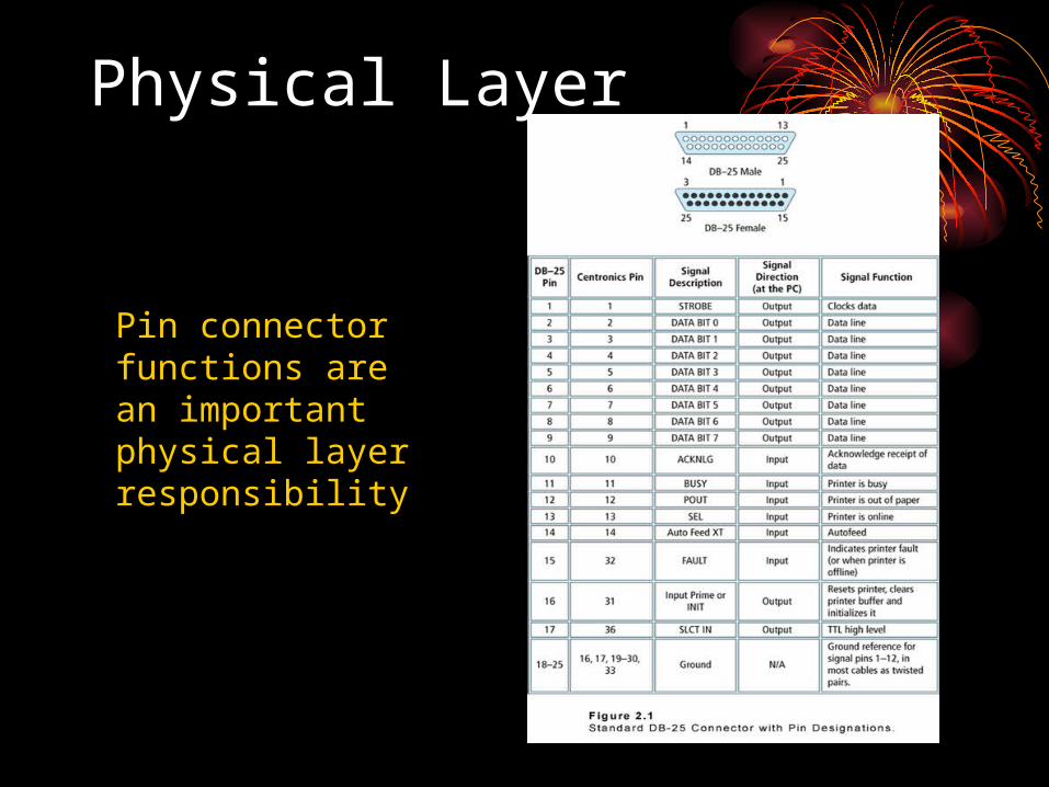
Physical Layer
Pin connector functions are an important physical layer responsibility

Signaling Methods -- 1st Component of the Physical Layer
• Analog versus Digital• Analog is continuous• Digital is discrete
• Analog uses modulation techniques• Amplitude, Frequency, Phase, for example• Analog is measured in hertz
• Digital uses encoding schemes• Manchester and Differential Manchester, for example• Digital is measured in bps, or bits per second

Analog Signaling Methods
• Can take an infinite form• Modulate a sine wave• Can change a wave’s
amplitude, frequency, or phase
• Amplitude affects the wave’s height or strength
• Frequency measures the waves per second
• Phase occurs when a wave changes direction
• Modulation is either Simple or Complex

Analog Signaling Methods

Analog Signaling Methods

Analog Signaling Methods
A hertz is a unit of frequency. A period is measured in seconds.

Analog Signaling Methods

Analog Signaling Methods
• Simple signal methods use:• A choice of two amplitudes, or• A choice of two frequencies, or• A single phase change
• A simple signal method has the same symbol and bit rate

Analog Signaling Methods
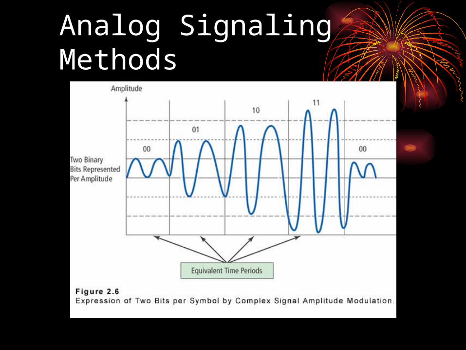
• A complex signal method occurs when the bit rate and the symbol rate are not the same:• A symbol, or baud, rate can represent more than one bit
per time period• When more then one bit is represented within a single
symbol, then the symbol and bit rates differ• Complex signal methods require that more than one bit be
represented per symbol• Complex signal methods combine different amplitudes,
frequencies, or phases, or some combination of these
Analog Signaling Methods

Analog Bandwidth
• Analog bandwidth is measured in hertz
• The bandwidth measurement is the difference between a given analog’s lowest and highest frequencies
• The spectrum consists of the entire range of frequencies, from lowest to highest

Analog Bandwidth andFrequency Spectrum Example

Digital Signaling Methods
• Are discrete, not continuous
• Take the value of a binary 0 or binary 1
• Make use of encoding schemes such as:• Manchester
• Ethernet
• Differential Manchester• Token Ring

Digital Signaling Methods

Digital Signaling Methods
• Make use of a “bit interval”, the time required to send a single bit
• The sender and receiver can use this bit interval to clock their transmission with each other
• With the bit interval as a clocking mechanism• The sender and receiver can synchronize their
transmissions• However, self-clocking mechanisms are more efficient
• A bit rate is also associated with a digital signaling method • The bit rate is the number of bit intervals per second, or bps

Digital Bandwidth
• Digital bandwidth is typically expressed in bits per second (bps)
• Digital bandwidth is determined using the bit interval and the bit rate
• Assuming we have a digital signal with a bit interval of 60 microseconds, what is its bandwidth? • The formula is expressed as: bps = 1 / (60 * 10-6), or
approximately 16.6 Kbps (thousands of bits per second)

Transmitting Encoded Data• The bits that represent encoded characters can be transmitted
simultaneously (parallel transmission) or one at time (serial transmission)
• Serial transmission is more widely used than parallel transmission for data communication
• Parallel transmission is used for communication between components within a computer
• In serial transmission, encoded characters can either be transmitted one at a time (asynchronous transmission) or in blocks (synchronous transmission) –
• UART provides the interface between parallel transmission within the computer and serial transmission ports. It also plays a key role in formatting encoded characters for asynchronous transmission

Digital Signaling Methods

Circuit Configuration -- 2nd Component of the Physical Layer
• Two major categories• Point-to-point• Multipoint
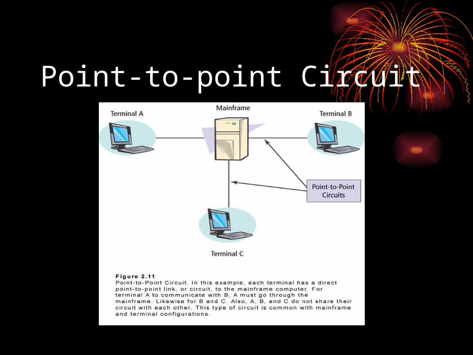
• Point-to-point circuits are dedicated links between two communicating devices
• Multipoint circuits are shared among several communicating devices
• Either could be appropriate based on network need
Point-to-point Circuit

Multipoint or Multidrop Circuit

Transmission Medium -- 3rd Component of the Physical Layer
• Two major categories• Conducted• Radiated
• Conducted – Makes use of cables• Twisted wire pair, coaxial cable, fiber optic
• Radiated – is “In the Air”• Terrestrial microwave, satellite, radio, infrared

Conducted MediaUse Cable
• An example of category 5, unshielded twisted wire pair
• An example of a coaxial cable, with its layered sheathing

Conducted MediaUse Cable
• Single mode fiber Cable with Connectors
• Fiber cores are measured in microns
• Another type of fiber is multimode
• Fiber is composed of either glass or plastic strands

Radiated Media, Signals “in the air”

Transmission MediumConsiderations
• Cost
• Bandwidth
• Security
• Transmission Impairment
• Distance

Transmission MediumImpairment
Considerations• Attenuation• Cross talk• Distortion• Environmental factors
• Rain, fog, snow, cloud cover, electrical or magnetic storms
• Of the various media, fiber optic is the least susceptible to impairment, and the most secure• But also very expensive!
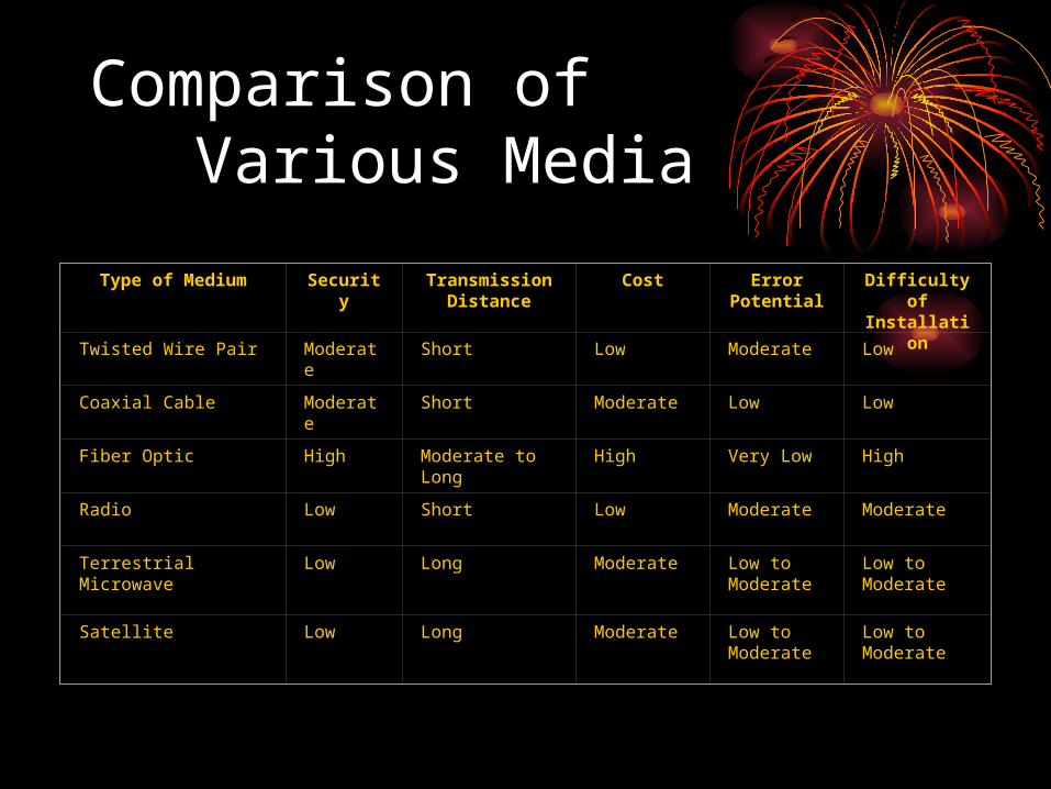
Comparison ofVarious Media
Type of Medium Security Transmission Distance
Cost Error Potential
Difficulty of Installation
Twisted Wire Pair Moderate Short Low Moderate Low
Coaxial Cable Moderate Short Moderate Low Low
Fiber Optic High Moderate to Long High Very Low High
Radio Low Short Low Moderate Moderate
Terrestrial Microwave Low Long Moderate Low to Moderate
Low to Moderate
Satellite Low Long Moderate Low to Moderate
Low to Moderate
Devices at the Physical Layer -- 4th Component of the Physical Layer
• Hubs or Repeaters
• Modems
• Codecs
• Multiplexers
• Cabling Tools (Not devices, but still important)

Devices at the Physical Layer -- 4th Component of the Physical Layer
Multiplexing
• Allows slower-speed circuit devices to share a single high-speed circuit
• In many cases, individual devices do not need their own high-speed circuit
• Type of multiplexing include:• Frequency division• Time division• Statistical time division • Wavelength division

Frequency Division Multiplexing
• A single high-speed circuit with multiple channel frequencies
• The circuit is analog• Bandwidth is measured in hertz• Data transmitted via channels • Viewed as horizontal• Makes use of guardbands as overhead

Frequency Division Multiplexing

Time Division Multiplexing
• A single high-speed circuit carrying multiple frames
• Time slots may only be used by specifically allocated devices
• The circuit is digital• Bandwidth is measured in bits per second (bps)• Data transmitted via frames• Viewed as vertical• Unused time slots create overhead

Time Division Multiplexing

Statistical Time Division Multiplexing
• A single high-speed circuit carrying multiple frames
• Time slots can be allocated to devices as needed• Time slots must carry addressing• The circuit is digital• Bandwidth is measured in bits per second• Data transmitted via frames• Viewed as vertical, not horizontal• Addressing of time slots creates overhead

Statistical Time Division Multiplexing

Wavelength DivisionMultiplexing
• Makes use of fiber optics• Operates in a manner somewhat similar to the way that
frequency division multiplexing is used with copper• Uses lasers to transmit different frequencies of light
through the same fiber optic cable• At the sending end, narrow bands of light are combined
into a wider band• The wider band is the high-speed circuit• At the receiving end, the signals are separated

Error Sources
• There are many sources of data communication transmission errors including:• Signal attenuation• Impulse noise• Crosstalk• Echo• Phase jitter• Envelope delay distortion• White noise• Electromagnetic interference (EMI)

Error Impacts
• Errors cause bits to be changed (corrupted) during transmission; without error-detection mechanisms, erroneous data could be received and used in application processing
• Figure 6-32 illustrates a transmission error caused by noise
• Table 6-8 indicates that longer impulse noises can corrupt multiple bits, especially as transmission speed increases
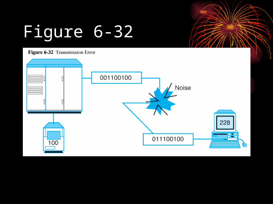
Figure 6-32

Table 6-8

Error Prevention
• Error prevention approaches used in data communications include:• Line conditioning• Adaptive protocols (such as adaptive line
probing, fallback, adaptive size packet assembly)• Shielding• Repeaters and amplifiers• Better equipment• Flow control
• RTS/CTS• XON/OFF

Error Detection Approaches• Error detection processes vary in complexity
and robustness. They include:• Parity checking (see Table 6-9)• Longitudinal redundancy checks (LRC) – see Table 6-10• Checksums• Cyclical redundancy checks (most widely used and
robust)• CRC-12• CRC-16• CRC-32
• Sequence checks• Other approaches include check digits, hash totals,
byte counts, and character echoing

Table 6-9
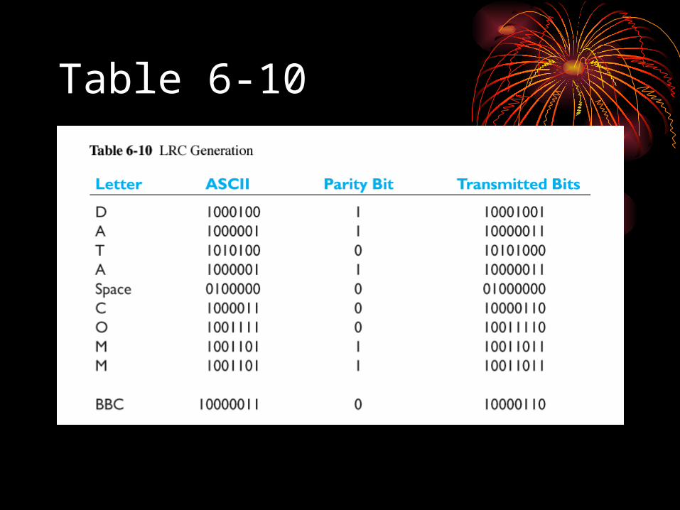
Table 6-10

Error Recovery• Automatic repeat request (ARQ) is the most widely used error-
recovery approach in data communications. In this approach, the receiver requests retransmission if an error occurs. There are three major kinds of ARQ:
• Discrete ARQ (aka stop-and-wait ARQ). Sender waits for an ACK or NAK before transmitting another packet
• Continuous ARQ (aka go-back-N ARQ). Sender keeps transmitting until a NAK is returned; sender retransmits that packet and all others after it
• Selective ARQ. Sender only retransmits packets with errors• Forward error correction codes involve sending additional redundant
information with the data to enable receivers to correct some of the errors they detect. Hamming code and Trellis Coded Modulation are examples
• Error control/recovery standards include MNP Class 4, V.42, and LAP-M (see Table 6-12)

In Summary • The physical layer:
• In the OSI and TCP/IP models is similar
• Is essential for transporting of data bits from sender to receiver
• Has circuits that are Conducted or Radiated
• Passes its unformatted data bit stream up to the Data Link Layer