business process modeling notation - omg.org draft.… · the business process modeling notation...
TRANSCRIPT
Business Process Management Initiative (BPMI)
Business Process Modeling Notation
Working Draft (1.0) August 25, 2003
Copyright 2003, BPMI.org. All Rights Reserved
AbstractThe Business Process Modeling Notation (BPMN) specification provides a graphical notation for expressing business processes in a Business Process Diagram (BPD). The objective of BPMN is to support process management by both technical users and business users by providing a notation that is intuitive to business users yet able to represent complex process semantics. The BPMN specification also provides a mapping between the graphics of the notation to underlying the constructs of execution languages, particularly BPEL4WS.
Status of this DocumentThis document is the first working draft of the BPMN specification submitted for comments from the public by members of the BPMI initiative on August 25, 2003. It supersedes any previous version. It has been produced based on the work of the members of the BPMI Notation Working Group. Comments on this document and discussions of this document should be sent to [email protected]. This is a draft document and may be updated, replaced, or made obsolete by other documents at any time. It is inappropriate to refer to this document as other than “work in progress.”

BPMN Working Draft
AcknowledgementsThe author/editor of the specification:
Stephen A. White, IBM ([email protected])
The members of the BPMI Notation Working Group contributed to the development of this specification, including those who contributed to the editing of the specification:
Ashish Agrawal, Intalio ([email protected])Michael Anthony, International Performance Group ([email protected])
Assaf Arkin, Intalio ([email protected])Tony Fletcher, Choreology ([email protected])Steven Forgey, SeeBeyond Technology Corporation ([email protected])Jean-Luc Giraud, Axway Software ([email protected])George Keeling, Casewise ([email protected])Brian James, Proforma ([email protected])Antoine Lonjon, Mega International ([email protected])Martin Owen, Popkin Software ([email protected])Manfred Sturm, ITPearls AG ([email protected])Steve Ball, Sterling Commerce ([email protected])Paul Vincent, Fair, Isaac & Company ([email protected])
The members of the BPMI Notation Working Group would like to thank SeeBeyond Technology Corporation for their valuable support in the development of this specification.
Notice of BPMI.org Policies on Intellectual Property Rights & Copyright
BPMI.org takes no position regarding the validity or scope of any intellectual property or other rights that might be claimed to pertain to the implementation or use of the technology described in this document or the extent to which any license under such rights might or might not be available; neither does it represent that it has made any effort to identify any such rights. Information on BPMI.org's procedures with respect to rights in BPMI.org specifications can be found at the BPMI.org website. Copies of claims of rights made available for publication and any assurances of licenses to be made available, or the result of an attempt made to obtain a general license or permission for the use of such proprietary rights by implementers or users of this specification, can be obtained from the BPMI.org Chairman. BPMI.org invites any interested party to bring to its attention any copyrights, patents or patent applications, or other proprietary rights, which may cover technology that may be required to implement this specification. Please address the information to the BPMI.org Chairman.This document and translations of it may be copied and furnished to others, and derivative works that comment on or otherwise explain it or assist in its implementation may be
2 / 189 Copyright 2003, BPMI.org All Rights Reserved

BPMN Working Draft
prepared, copied, published and distributed, in whole or in part, without restriction of any kind, provided that the above copyright notice and this paragraph are included on all such copies and derivative works. However, this document itself may not be modified in any way, such as by removing the copyright notice or references to BPMI.org, except as needed for the purpose of developing BPMI.org specifications, in which case the procedures for copyrights defined in the BPMI.org Intellectual Property Rights document must be followed, or as required to translate it into languages other than English.The limited permissions granted above are perpetual and will not be revoked by BPMI.org or its successors or assigns.This document and the information contained herein is provided on an "AS IS" basis and BPMI.org DISCLAIMS ALL WARRANTIES, EXPRESS OR IMPLIED, INCLUDING BUT NOT LIMITED TO ANY WARRANTY THAT THE USE OF THE INFORMATION HEREIN WILL NOT INFRINGE ANY RIGHTS OR ANY IMPLIED WARRANTIES OF MERCHANTABILITY OR FITNESS FOR A PARTICULAR PURPOSE.Copyright © The Business Process Management Initiative [BPMI.org], August 25, 2003. All Rights Reserved.
Copyright 2003, BPMI.org All Rights Reserved 3 / 189

BPMN Working Draft
Table of ContentsAbstract.................................................................................................................................................1Status of this Document.......................................................................................................................1Acknowledgements ..............................................................................................................................2Notice of BPMI.org Policies on Intellectual Property Rights & Copyright ...................................2Table of Contents .................................................................................................................................4List of Figures.......................................................................................................................................8List of Tables ......................................................................................................................................12List of Examples.................................................................................................................................131. Introduction....................................................................................................................................14
1.1 Conventions ...............................................................................................................................151.1.1 Typographical and Linguistic Conventions and Style ..........................................................15
1.2 Dependency on Other Specifications.......................................................................................161.3 Conformance .............................................................................................................................16
2. BPMN Overview ............................................................................................................................192.1 BPMN Scope..............................................................................................................................20
2.1.1 Uses of BPMN ......................................................................................................................202.1.2 Diagram Point of View ........................................................................................................232.1.3 Extensibility of BPMN and Vertical Domains .....................................................................24
3. Business Process Diagrams ...........................................................................................................253.1 BPD Core Element Set .............................................................................................................253.2 BPD Complete Set.....................................................................................................................273.3 Use of Text, Color, Size, and Lines in a Diagram ..................................................................343.4 Flow Object Connection Rules ................................................................................................35
3.4.1 Sequence Flow Rules............................................................................................................353.4.2 Message Flow Rules .............................................................................................................36
3.5 Diagram Attributes...................................................................................................................374. Business Process Diagram Graphical Objects ............................................................................39
4.1 Common BPD Object Attributes.............................................................................................394.2 Events .........................................................................................................................................39
4.2.1 Start .......................................................................................................................................404.2.2 End ........................................................................................................................................444.2.3 Intermediate ..........................................................................................................................48
4.3 Activities ....................................................................................................................................524.3.1 Process ..................................................................................................................................524.3.2 Sub-Process...........................................................................................................................544.3.3 Task.......................................................................................................................................60
4.4 Gateways....................................................................................................................................64
4 / 189 Copyright 2003, BPMI.org All Rights Reserved

BPMN Working Draft Table of Contents
4.4.1 Common Gateway Features..................................................................................................664.4.2 Exclusive Gateways (XOR)..................................................................................................674.4.3 Inclusive Gateways (OR)......................................................................................................754.4.4 Complex Gateways ...............................................................................................................784.4.5 Parallel Gateways (AND) .....................................................................................................81
4.5 Pools and Lanes.........................................................................................................................834.5.1 Pool .......................................................................................................................................834.5.2 Lane ......................................................................................................................................86
4.6 Artifacts .....................................................................................................................................874.6.1 Common Artifact Attributes .................................................................................................884.6.2 Artifact Sequence Flow Connections ...................................................................................884.6.3 Artifact Message Flow Connections.....................................................................................884.6.4 Data Object ...........................................................................................................................884.6.5 Text Annotation ....................................................................................................................904.6.6 Group ....................................................................................................................................91
5. Connecting Objects........................................................................................................................935.1 Graphical Connecting Objects ................................................................................................93
5.1.1 Sequence Flow......................................................................................................................935.1.2 Message Flow .......................................................................................................................965.1.3 Association............................................................................................................................99
5.2 Sequence Flow Mechanisms...................................................................................................1015.2.1 Normal Flow .......................................................................................................................1025.2.2 Link Events .........................................................................................................................1215.2.3 Exception Flow ...................................................................................................................1215.2.4 Ad Hoc................................................................................................................................122
5.3 Compensation Association .....................................................................................................1246. BPMN by Example ......................................................................................................................127
6.1 The Beginning of the Process .................................................................................................1286.1.1 Mapping to BPEL4WS .......................................................................................................128
6.2 The First Sub-Process.............................................................................................................1336.2.1 Mapping to BPEL4WS .......................................................................................................135
6.3 The Second Sub-Process.........................................................................................................1396.3.1 Mapping to BPEL4WS .......................................................................................................141
6.4 The End of the Process ...........................................................................................................1466.4.1 Mapping to BPEL4WS .......................................................................................................147
7. Mapping to XML Languages......................................................................................................1537.1 Defining Token Generation for execution Language Mapping..........................................1537.2 Mapping to BPEL4WS...........................................................................................................154
7.2.1 Events..................................................................................................................................1547.2.2 Activities .............................................................................................................................1577.2.3 Gateways.............................................................................................................................159
Copyright 2003, BPMI.org All Rights Reserved 5 / 189

BPMN Working Draft
7.2.4 Pool .....................................................................................................................................1617.2.5 Lane ....................................................................................................................................1617.2.6 Artifacts ..............................................................................................................................1617.2.7 Sequence Flow....................................................................................................................1617.2.8 Message Flow .....................................................................................................................1627.2.9 Association..........................................................................................................................1627.2.10 Exception Flow .................................................................................................................1627.2.11 Compensation Flow ..........................................................................................................163
8. References.....................................................................................................................................1658.1 Normative ................................................................................................................................1658.2 Non-Normative........................................................................................................................165
9. Open Issues ...................................................................................................................................169Appendix A: E-Mail Voting Process BPEL4WS ..........................................................................171Appendix B: Glossary......................................................................................................................179
6 / 189 Copyright 2003, BPMI.org All Rights Reserved

BPMN Working Draft Table of Contents
Copyright 2003, BPMI.org All Rights Reserved 7 / 189
BPMN Working Draft
List of FiguresFigure 1: A Business Process Diagram with Two Points of View .................................................23Figure 2: A Start Event .....................................................................................................................40Figure 3: End Event...........................................................................................................................44Figure 4: Intermediate Event............................................................................................................48Figure 5: Task with an Intermediate Event attached to its boundary..........................................49Figure 6: Collapsed Sub-Process ......................................................................................................54Figure 7: Expanded Sub-Process......................................................................................................54Figure 8: Expanded Sub-Process used as a “parallel box”............................................................55Figure 9: Collapsed Sub-Process Markers ......................................................................................55Figure 10: An Example of a Transaction Expanded Sub-Process ................................................58Figure 11: A Task Object ..................................................................................................................61Figure 12: Task Markers ..................................................................................................................61Figure 13: A Gateway........................................................................................................................65Figure 14: The Different types of Gateways....................................................................................66Figure 15: An Exclusive Data-Based Decision (Gateway) Example without the Internal Indicator68Figure 16: A Data-Based Exclusive Decision (Gateway) Example with the Internal Indicator.68Figure 17: An Exclusive Merge (Gateway) (without the Internal Indicator)...............................69Figure 18: Uncontrolled Merging of Sequence Flow......................................................................70Figure 19: Exclusive Gateway that merges Sequence Flow prior to an Parallel Gateway .........70Figure 20: An Event-Based Decision (Gateway) Example Using Receive Tasks .........................73Figure 21: An Event-Based Decision (Gateway) Example Using Message Events ......................73Figure 22: An Inclusive Decision using Conditional Sequence Flow ............................................76Figure 23: An Inclusive Decision using an OR Gateway ...............................................................76Figure 24: An Inclusive Gateway Merging Sequence Flow ...........................................................77Figure 25: A Complex Decision (Gateway) .....................................................................................79Figure 26: A Complex Merge (Gateway).........................................................................................79Figure 27: A Parallel Gateway .........................................................................................................81Figure 28: Joining – the joining of parallel paths ...........................................................................82Figure 29: A Pool ...............................................................................................................................83Figure 30: Message Flow connecting to the boundaries of two Pools ...........................................84Figure 31: Message Flow connecting to flow objects within two Pools.........................................85Figure 32: Main (Internal) Pool without boundaries .....................................................................85Figure 33: Two Lanes in a Pool ........................................................................................................87Figure 34: A Data Object ..................................................................................................................89Figure 35: A Data Object associated with a Sequence Flow..........................................................89
8 / 189 Copyright 2003, BPMI.org All Rights Reserved

BPMN Working Draft List of Figures
Figure 36: Data Objects shown as inputs and outputs ...................................................................90Figure 37: A Text Annotation...........................................................................................................91Figure 38: A Group Artifact .............................................................................................................91Figure 39: A Group around activities in different Pools................................................................92Figure 40: A Sequence Flow .............................................................................................................93Figure 41: A Conditional Sequence Flow ........................................................................................94Figure 42: A Default Sequence Flow................................................................................................94Figure 43: A Message Flow ...............................................................................................................96Figure 44: Message Flow connecting to the boundaries of two Pools ...........................................96Figure 45: Message Flow connecting to flow objects within two Pools.........................................97Figure 46: Message Flow connecting to boundary of Sub-Process and Internal objects............98Figure 47: An Association .................................................................................................................99Figure 48: A directional Association..............................................................................................100Figure 49: An Association of Text Annotation..............................................................................100Figure 50: An Association connecting a Data Object with a Flow..............................................100Figure 51: Workflow Pattern #1: Sequence ..................................................................................102Figure 52: A Process with Normal flow .........................................................................................102Figure 53: A Process with Expanded Sub-Process without a Start Event and End Event .......103Figure 54: A Process with Expanded Sub-Process with a Start Event and End Event Internal ...104Figure 55: A Process with Expanded Sub-Process with a Start Event and End Event Attached to Boundary ..........................................................................................................................................104Figure 56: Workflow Pattern #2: Parallel Split -- Version 1 .......................................................105Figure 57: Workflow Pattern #2: Parallel Split -- Version 2 .......................................................105Figure 58: The Creation of Parallel Paths with a Gateway .........................................................106Figure 59: The Creation of Parallel Paths with Equivalent Conditions .....................................106Figure 60: Workflow Pattern #2: Parallel Split -- Version 3 .......................................................107Figure 61: Workflow Pattern #3: Synchronization -- Version 1 .................................................107Figure 62: Workflow Pattern #3: Synchronization -- Version 2 .................................................108Figure 63: The Fork-Join Relationship is not Fixed.....................................................................108Figure 64: A Data-Based Decision Example -- Workflow Pattern #4 -- Exclusive Choice .......109Figure 65: Workflow Pattern #6 -- Multiple Choice -- Version 1................................................110Figure 66: Workflow Pattern #6 -- Multiple Choice -- Version 2................................................110Figure 67: A Complex Decision (Gateway) ...................................................................................111Figure 68: An Event-Based Decision Example..............................................................................111Figure 69: Workflow Pattern #5 -- Simple Merge – Version 1....................................................112Figure 70: Workflow Pattern #7 -- Multiple Merge .....................................................................113Figure 71: Workflow Pattern #5 -- Simple Merge – Version 2....................................................113
Copyright 2003, BPMI.org All Rights Reserved 9 / 189

BPMN Working Draft
Figure 72: Workflow Pattern #8 -- Discriminator ........................................................................114Figure 73: Workflow Pattern #9 -- Synchronizing Join ...............................................................114Figure 74: Workflow Pattern #8 -- N out of M Join .....................................................................115Figure 75: The Split-Merge Relationship is not Fixed .................................................................115Figure 76: A Task and a Collapsed Sub-Process with a Loop Marker ......................................117Figure 77: A Task with a Parallel Marker ....................................................................................117Figure 78: An Expanded Sub-Process with a Loop Marker........................................................117Figure 79: Workflow Pattern #16 -- Arbitrary Cycle...................................................................118Figure 80: An Until Loop ................................................................................................................118Figure 81: A While Loop.................................................................................................................118Figure 82: Example of Sub-Process ...............................................................................................119Figure 83: Potentially a dead-locked model ..................................................................................120Figure 84: Improper Looping.........................................................................................................120Figure 85: A Task with Exception Flow (Interrupts Event Context) .........................................121Figure 86: A Sub-Process with Exception Flow (Interrupts Event Context) .............................122Figure 87: A Collapsed Ad Hoc Sub-Process ................................................................................123Figure 88: An Expanded Ad Hoc Sub-Process .............................................................................123Figure 89: An Ad Hoc Process for Writing a Book Chapter .......................................................123Figure 90: A Task with an Associated Compensation Activity ...................................................124Figure 91: Compensation Shown in the context of a Transaction ..............................................125Figure 92: E-Mail Voting Process ..................................................................................................127Figure 93: The Start of the Process ................................................................................................128Figure 94: The Ongoing Starter Process .......................................................................................129Figure 95: “Discussion Cycle” Sub-Process Details......................................................................133Figure 96: “Collect Votes” Sub-Process Details............................................................................140Figure 97: The last segment of the E-Mail Voting Process ..........................................................146Figure 98: Message Flow connected to a Start Event...................................................................154Figure 99: Process Instantiation through Message Receiving Task............................................155Figure 100: Message Flow leaving an End Event .........................................................................155Figure 101: Message Flow from Task that precedes the End Event...........................................156
10 / 189 Copyright 2003, BPMI.org All Rights Reserved

BPMN Working Draft List of Figures
Copyright 2003, BPMI.org All Rights Reserved 11 / 189
BPMN Working Draft
12 / 189 Copyright 2003, BPMI.org All Rights Reserved
List of TablesTable 1: BPD Core Element Set .......................................................................................................26Table 2: BPD Complete Element Set ...............................................................................................34Table 3: Sequence Flow Connection Rules......................................................................................36Table 4: Message Flow Connection Rules .......................................................................................37Table 5: Business Process Diagram Attributes ...............................................................................37Table 6: Common Object Attributes ...............................................................................................39Table 7: Start Event Types ...............................................................................................................42Table 8: Start Event Attributes ........................................................................................................43Table 9: End Event Types .................................................................................................................46Table 10: End Event Attributes........................................................................................................47Table 11: Intermediate Event Types ................................................................................................50Table 12: Intermediate Event Attributes.........................................................................................51Table 13: Process Attributes .............................................................................................................53Table 14: Sub-Process Attributes .....................................................................................................57Table 15: Task Attributes .................................................................................................................63Table 16: Common Gateway Attributes ..........................................................................................66Table 17: Data-Based Exclusive Gateway Attributes.....................................................................71Table 18: Event-Based Exclusive Gateway Attributes ...................................................................74Table 19: Inclusive Gateway Attributes ..........................................................................................77Table 20: Complex Gateway Attributes ..........................................................................................80Table 21: Parallel Gateway Attributes ............................................................................................82Table 22: Pool Attributes ..................................................................................................................86Table 23: Lane Attributes .................................................................................................................87Table 24: Common Artifact Attributes............................................................................................88Table 25: Data Object Attributes .....................................................................................................90Table 26: Text Annotation Attributes..............................................................................................91Table 27: Sequence Flow Attributes ................................................................................................95Table 28: Message Flow Attributes ..................................................................................................99Table 29: Association Attributes ....................................................................................................101
BPMN Working Draft
Copyright 2003, BPMI.org All Rights Reserved 13 / 189
List of ExamplesExample 1: BPEL4WS Sample for Beginning of E-Mail Voting Process ..................................133Example 2: BPEL4WS Sample of “Discussion Cycle” Sub-Process Details ..............................139Example 3: BPEL4WS Sample that sets up the Access for the Second Sub-Process ................142Example 4: BPEL4WS Sample of the Second Sub-Process .........................................................145Example 5: Sample BPEL4WS code for the last section of the Process .....................................150Example 6: Sample BPEL4WS code for derived process for repeated elements ......................151
BPMN Working Draft
1. IntroductionThe Business Process Management Initiative (BPMI) has developed a standard Business Process Modeling Notation (BPMN). The primary goal of BPMN is to provide a notation that is readily understandable by all business users, from the business analysts that create the initial drafts of the processes, to the technical developers responsible for implementing the technology that will perform those processes, and finally, to the business people who will manage and monitor those processes. Thus, BPMN creates a standardized bridge for the gap between the business process design and process implementation.
Another goal, but no less important, is to ensure that XML languages designed for the execution of business processes, such as BPEL4WS (Business Process Execution Language for Web Services), can be visualized with a common notation.
This specification defines the notation and semantics of a Business Process Diagram (BPD) and represents the amalgamation of best practices within the business modeling community. The intent of BPMN is to standardize a business process modeling notation in the face of many different modeling notations and viewpoints. In doing so, BPMN will provide a simple means of communicating process information to other business users, process implementers, customers, and suppliers. The membership of the BPMI Notation Working Group has brought forth expertise and experience with the many existing notations and has sought consolidate the best ideas from these divergent notations into a single standard notation. Examples of other notations or methodologies that were reviewed are UML Activity Diagram, UML EDOC Business Processes, IDEF, ebXML BPSS, Activity-Decision Flow (ADF) Diagram, RosettaNet, LOVeM, and Event-Process Chains (EPCs).
The BPMN specification defines a mapping from BPMN to BPEL4WS and is comprised of the following topics:
BPMN Overview provides an introduction to BPMN, its requirements, and discusses the range of modeling purposes that BPMN can convey.
Business Process Diagrams provides a summary of the BPMN graphical elements and their relationships.
Business Process Diagram Graphical Objects details the graphical representation and the semantics of the behavior of BPMN Diagram elements.
Connecting Objects defines the graphical objects used to connect two objects together (i.e., the connecting lines of the Diagram) and how flow progresses through a Process (i.e., through a straight sequence or through the creation of parallel or alternative paths).
BPMN by Example provides a walkthrough of a sample Process using BPMN.
Mapping to XML Languages provides the formal mechanism for converting a BPMN Diagram to a BPEL4WS document.
References provides a list of normative and non-normative references.
Open Issues provides a list of issues that will affect the future of the BPMN specification.
Appendix A: E-Mail Voting Process BPEL4WS provides a full sample of BPEL4WS code based on the example business process described in the “BPMN by Example” section.
Appendix B: Glossary presents an alphabetical index of terms that are relevant to practitioners of BPMN.
Copyright 2003, BPMI.org All Rights Reserved 14 / 189

BPMN Working Draft 1. Introduction
1.1 ConventionsThe section introduces the conventions used in this document. This includes (text) notational conventions and notations for schema components. Also included are designated namespace definitions.
1.1.1 Typographical and Linguistic Conventions and StyleThis specification incorporates the following conventions:
• The keywords “MUST,” “MUST NOT,” “REQUIRED,” “SHALL,” “SHALL NOT,” “SHOULD,” “SHOULD NOT,” “RECOMMENDED,” “MAY,” and “OPTIONAL” in this document are to be interpreted as described in RFC-2119.
• A term is a word or phrase that has a special meaning. When a term is defined, the term name is highlighted in bold typeface.
• A reference to another definition, section, or specification is highlighted with underlined typeface and provides a link to the relevant location in this specification.
• A reference to an element, attribute, or BPMN construct is highlighted with a capitalized word (e.g., Sub-Process).
• A reference to a BPEL4WS element, attribute, or construct is highlighted with an italic lower-case word, usually preceded by the word “BPEL4WS” (e.g., BPEL4WS pick).
• Non-normative examples are set of in boxes and accompanied by a brief explanation.
• XML and pseudo text is highlighted with mono-spaced typeface.
• The cardinality of any content part is specified using the following operators:
• (none) — exactly once
• ? — 0 or 1
• * — 0 or more
• + — 1 or more
• Properties separated by | and grouped within ( and ) — alternative values
• : <value> — default value
Copyright 2002, BPMI.org All Rights Reserved 15 / 189
1.2 Dependency on Other Specifications BPMN Working Draft
1.2 Dependency on Other SpecificationsThe BPMN specification supports for the following specifications is a normative part of the BPMN specification: BPEL4WS.
The following abbreviations may be used throughout this document:
This abbreviation Refers to
BPEL4WS Business Process Execution Language for Web Services (see BPEL4WS). This abbreviation refers specifically to version 1.1 of the specification, but is intended to support future versions of the BPEL4WS specification.
WSDL Web Service Description Language (see WSDL). This abbreviation refers specifically to the W3C Technical Note, 15 March 2001, but is intended to support future versions of the WSDL specification.
1.3 ConformanceA BPMN implementation is responsible to perform one or more duties, as outlined below, based on the information contained in this specification.
There are four main aspects of conformance to the BPMN Specification:
• The visual appearance of the BPMN graphical elements. A key element of BPMN is the choice of shapes and icons used for the graphical elements identified in this specification. The intent is to create a standard visual language that all process modelers will recognize and understand, regardless of the source of the Diagram. Any tool that is used to create BPMN Diagrams MUST conform to the shapes and markers as defined in this specification. Note that there is flexibility in the size, color, line style, and text positions of the defined graphical elements. Extensions to a BPD are allowed as follows:
• Extensions can be made to the Diagram elements by way of new markers or indicators associated with the current graphical elements. These markers or indicators could be used to highlight a specific attribute of an activity or to create a new type of Event, for example. In addition, Extensions could also include coloring an object or changing a line style of an object, with the condition that change MAY NOT conflict with any current BPMN defined line style.
• Extensions MAY NOT change the basic shape of the defined graphical elements and markers (e.g., changing a square into a triangle, or changing rounded corners into squared corners, etc.).
• Any number of Artifacts, consisting of a variety of shapes, can be added to a Diagram, with the condition that the Artifact shape MAY NOT conflict with any current object shape or defined marker.
• The semantics of the BPMN elements. This specification also defines how the graphical elements will interact with each other, including conditional interactions based on attributes that create behavioral variations of the elements. A conformant tool MUST
16 / 189 Copyright 2003, BPMI.org All Rights Reserved

BPMN Working Draft 1. Introduction
adhere to these semantic definitions.
• Throughout the document, specific BPMN semantic definitions will be identified through a special diamond-shaped bulleted paragraph, as shown in the following example:
A Task MAY be a target for a Sequence Flow; it can have multiple incoming Flows. Incoming Flow MAY be from an alternative path and/or a parallel paths.
• The mapping of a BPMN Diagram to BPEL4WS. This draft of the specification will not have completed the mapping. When such a mapping has been completed, a conformant tool MUST adhere to the mapping rules defined in the section entitled “Mapping to XML Languages” on page 153. This conformance only applies to tools that generate BPEL4WS from BPMN Diagrams.
• The exchange of BPMN Diagrams between conformant tools. This draft of the specification will not contain a standard mechanism for Diagram exchange. The nature of this mechanism has not been defined yet. It could involve the development of a BPMN XML schema that is layered upon the BPEL4WS XML schema or it could involve the use of standard Diagram interchange formats, such a XMI. When an exchange mechanism has been defined, a conformant tool MUST be able to import and export BPMN Diagrams in the specified format.
A conformant implementation is not required to process any non-normative extension elements or attributes, or any BPMN document that contains them.
Copyright 2002, BPMI.org All Rights Reserved 17 / 189

BPMN Working Draft
Copyright 2003, BPMI.org All Rights Reserved 18 / 189
BPMN Working Draft 2. BPMN Overview
2. BPMN OverviewThere has been much activity in the past two or three years in developing web service-based XML execution languages for Business Process Management (BPM) systems. Languages such as BPEL4WS provide a formal mechanism for the definition of business processes. The key element of such languages is that they are optimized for the operation and inter-operation of BPM Systems. The optimization of these languages for software operations renders them less suited for direct use by humans to design, manage, and monitor business processes. BPEL4WS has both graph and block structures and utilizes the principles of formal mathematical models, such as pi-calculus1. This technical underpinning provides the foundation for business process execution to handle the complex nature of both internal and B2B interactions and take advantage of the benefits of Web services. Given the nature of BPEL4WS, a complex business process could be organized in a potentially complex, disjointed, and unintuitive format that is handled very well by a software system (or a computer programmer), but would be hard to understand by the business analysts and managers tasked to develop, manage, and monitor the process. Thus, there is a human level of “inter-operability” or “portability” that is not addressed by these web service-based XML execution languages.
Business people are very comfortable with visualizing business processes in a flow-chart format. There are thousands of business analysts studying the way companies work and defining business processes with simple flow charts. This creates a technical gap between the format of the initial design of business processes and the format of the languages, such as BPEL4WS, that will execute these business processes. This gap needs to be bridged with a formal mechanism that maps the appropriate visualization of the business processes (a notation) to the appropriate execution format (a BPM execution language) for these business processes.
Inter-operation of business processes at the human level, rather than the software engine level, can be solved with standardization of the Business Process Modeling Notation (BPMN). BPMN provides a Business Process Diagram (BPD), which is a Diagram designed for use by the people who design and manage business processes. BPMN also provides a formal mapping to an execution language of BPM Systems (BPEL4WS). Thus, BPMN would provide a standard visualization mechanism for business processes defined in an execution optimized business process language.
BPMN will provide businesses with the capability of understanding their internal business procedures in a graphical notation and will give organizations the ability to communicate these procedures in a standard manner. Currently, there are scores of process modeling tools and methodologies. Given that individuals will move from one company to another and that companies will merge and diverge, it is likely that business analysts are required to understand multiple representations of business processes--potentially different representations of the same process as it moves through its lifecycle of development, implementation, execution, monitoring, and analysis. Therefore, a standard graphical notation will facilitate the understanding of the performance collaborations and business transactions within and between the organizations. This will ensure that businesses will understand themselves and participants in their business and will enable organizations to
1.See Milner, 1999, “Communicating and Mobile Systems: the Π-Calculus,” Cambridge University Press. ISBN0 521 64320 1 (hc.) ISBN 0 521 65869 1 (pbk.)
Copyright 2002, BPMI.org All Rights Reserved 19 / 189
2.1 BPMN Scope BPMN Working Draft
adjust to new internal and B2B business circumstances quickly. To do this, BPMN will follow the tradition of flowcharting notations for readability; yet still provide the mapping to the executable constructs. BPMI is using the experience of the business process notations that have preceded BPMN to create the next generation notation that combines readability, flexibility, and expandability.
BPMN will also advance the capabilities of traditional business process notations by inherently handling B2B business process concepts, such as public and private processes and choreographies, as well as advanced modeling concepts, such as exception handling and transaction compensation.
2.1 BPMN ScopeBPMN will be constrained to support only the concepts of modeling that are applicable to business processes. This means that other types of modeling done by organizations for business purposes will be out of scope for BPMN. For example, the modeling of the following will not be a part of BPMN:
• Organizational structures
• Functional breakdowns
• Data models
In addition, while BPMN will show the flow of data (messages), and the association of data artifacts to activities, it is not a data flow Diagram.
2.1.1 Uses of BPMNBusiness process modeling is used to communicate a wide variety of information to a wide variety of audiences. BPMN is designed to cover this wide range of usage and allows modeling of end-to-end business processes to allow the viewer of the Diagram to be able to easily differentiate between sections of a BPMN Diagram.
There are three basic types of sub-models within an end-to-end BPMN model:
• Private (internal) business processes
• Abstract (public) processes
• Collaboration (global) Processes
Note: The terminology used to describe the different types of processes has not been standardized. Definitions of these terms are in flux. There is work being done in the World Wide Web Consortium (W3C) and in the Organization for the Advancement of Structured Information Standards (OASIS) that will hopefully consolidate these terms.
Some BPMN specification terms regarding the use of swimlanes (e.g., Pools and Lanes) are used in the descriptions below. Refer to the section entitled “Pools and Lanes” on page 83 for more details on how these elements are used in a BPD.
20 / 189 Copyright 2003, BPMI.org All Rights Reserved
BPMN Working Draft 2. BPMN Overview
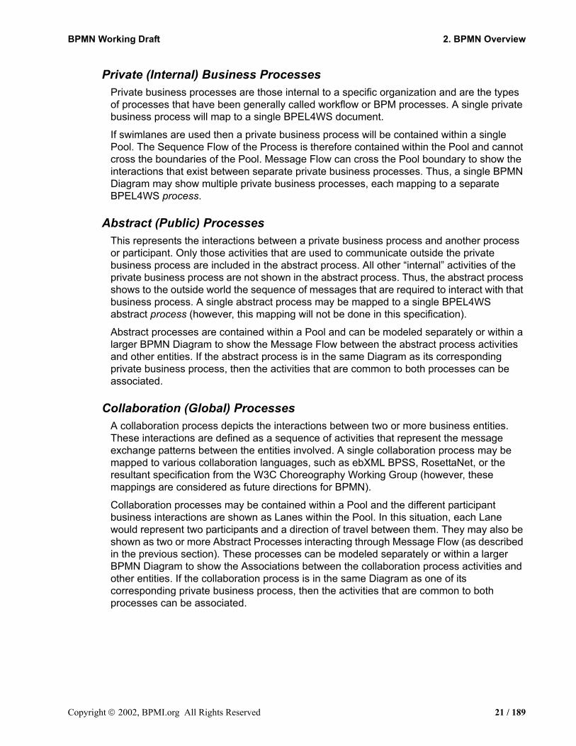
Private (Internal) Business ProcessesPrivate business processes are those internal to a specific organization and are the types of processes that have been generally called workflow or BPM processes. A single private business process will map to a single BPEL4WS document.
If swimlanes are used then a private business process will be contained within a single Pool. The Sequence Flow of the Process is therefore contained within the Pool and cannot cross the boundaries of the Pool. Message Flow can cross the Pool boundary to show the interactions that exist between separate private business processes. Thus, a single BPMN Diagram may show multiple private business processes, each mapping to a separate BPEL4WS process.
Abstract (Public) ProcessesThis represents the interactions between a private business process and another process or participant. Only those activities that are used to communicate outside the private business process are included in the abstract process. All other “internal” activities of the private business process are not shown in the abstract process. Thus, the abstract process shows to the outside world the sequence of messages that are required to interact with that business process. A single abstract process may be mapped to a single BPEL4WS abstract process (however, this mapping will not be done in this specification).
Abstract processes are contained within a Pool and can be modeled separately or within a larger BPMN Diagram to show the Message Flow between the abstract process activities and other entities. If the abstract process is in the same Diagram as its corresponding private business process, then the activities that are common to both processes can be associated.
Collaboration (Global) ProcessesA collaboration process depicts the interactions between two or more business entities. These interactions are defined as a sequence of activities that represent the message exchange patterns between the entities involved. A single collaboration process may be mapped to various collaboration languages, such as ebXML BPSS, RosettaNet, or the resultant specification from the W3C Choreography Working Group (however, these mappings are considered as future directions for BPMN).
Collaboration processes may be contained within a Pool and the different participant business interactions are shown as Lanes within the Pool. In this situation, each Lane would represent two participants and a direction of travel between them. They may also be shown as two or more Abstract Processes interacting through Message Flow (as described in the previous section). These processes can be modeled separately or within a larger BPMN Diagram to show the Associations between the collaboration process activities and other entities. If the collaboration process is in the same Diagram as one of its corresponding private business process, then the activities that are common to both processes can be associated.
Copyright 2002, BPMI.org All Rights Reserved 21 / 189

2.1 BPMN Scope BPMN Working Draft
Types of BPD DiagramsWithin and between these three BPMN sub-models, many types of Diagrams can be created. The following are the types of business processes that can be modeled with BPMN (those with asterisks may not map to an executable language):
• High-level private process activities (not functional breakdown)*
• Detailed private business process
• As-is or old business process*
• To-be or new business process
• Detailed private business process with interactions to one or more external entities (or “Black Box” processes)
• Two or more detailed private business processes interacting
• Detailed private business process relationship to Abstract Process
• Detailed private business process relationship to Collaboration Process
• Two or more Abstract Processes*
• Abstract Process relationship to Collaboration Process*
• Collaboration Process only (e.g., ebXML BPSS or RosettaNet)*
• Two or more detailed private business processes interacting through their Abstract Processes
• Two or more detailed private business processes interacting through a Collaboration Process
• Two or more detailed private business processes interacting through their Abstract Processes and a Collaboration Process
BPMN is designed to allow all the above types of Diagrams. However, it should be cautioned that if too many types of sub-models are combined, such as three or more private processes with message flow between each of them, then the Diagram may become too hard for someone to understand. Thus, we recommend that the modeler pick a focused purpose for the BPD, such as a private process, or a collaboration process.
BPMN mappingsSince BPMN covers such a wide range of usage, it will map to more than one lower-level specification language:
• BPEL4WS are the primary languages that BPMN will map to, but they only cover a single executable private business process. If a BPMN Diagram depicts more than one internal business process, then there will a separate mapping for each on the internal business processes.
• The abstract sections of a BPMN Diagram will be mapped to Web service interfaces specifications, such as the abstract processes of BPEL4WS.
• The Collaboration model sections of a BPMN will be mapped Collaboration models such as ebXML BPSS, RosettaNet, and the W3C Choreography Working Group
22 / 189 Copyright 2003, BPMI.org All Rights Reserved

BPMN Working Draft 2. BPMN Overview
Specification (when it is completed).
This specification will only cover the mappings to BPEL4WS. Mappings to other specifications will have to be a separate effort, or perhaps a future direction of BPMN (beyond Version 1.0 of the BPMN specification). It is hard to predict which mappings will be applied to BPMN at this point, since process language specifications is a volatile area of work, with many new offerings and mergings.
A BPD is not designed to graphically convey all the information required to execute a business process. Thus, the graphic elements of BPMN will be supported by attributes that will supply the additional information required to enable a mapping to BPEL4WS.
2.1.2 Diagram Point of ViewSince a BPMN Diagram may depict the Processes of different Participants, each Participant may view the Diagram differently. That is, the Participants have different points of view regarding how the Processes will behave. Some of the activities will be internal to the Participant (meaning performed by or under control of the Participant) and other activities will be external to the Participant. Each Participant will have a different perspective as to which are internal and external. At runtime, the difference between internal and external activities is important in how a Participant can view the status of the activities or trouble-shoot any problems. However, the Diagram itself remains the same. Figure 1 displays a simple Business Process that has two points of view. One point of view is of a Patient, the other is of the Doctor’s office. The Diagram shows the activities of both participants in the Process, but when the Process is actually being performed, each Participant will really have control over their own activities.
Figure 1 A Business Process Diagram with Two Points of View
Patie
ntR
ecep
tioni
st/
Doc
tor
Send DoctorRequest
1) I want to see doctor
IllnessOccurs
Send Appt.
Receive Appt.
5) Go see doctor
SendSymptoms
ReceiveSymptoms
6) I feel sick
ReceivePrescription
Pickup
8) Pickup your medicineand you can leave
Send MedicineRequest
ReceiveMedicineRequest
9) need my medicine
ReceiveMedicine
10) Here is your medicine
ReceiveDoctor
RequestSend Medicine
SendPrescription
Pickup
Copyright 2002, BPMI.org All Rights Reserved 23 / 189

2.1 BPMN Scope BPMN Working Draft
Although the Diagram point of view is important for a viewer of the Diagram to understand how the behavior of the Process will relate to that viewer, BPMN will not currently specify any graphical mechanisms to highlight the point of view. It is open to the modeler or modeling tool vendor to provide any visual cues to emphasize this characteristic of a Diagram.
2.1.3 Extensibility of BPMN and Vertical DomainsBPMN is intended to be extensible by modelers and modeling tools. This extensibility allows modelers to add non-standard elements or artifacts to satisfy a specific need, such as the unique requirements of a vertical domain. While extensible, BPMN Diagrams should still have the basic look-and-feel so that a Diagram by any modeler should be easily understood by any viewer of the Diagram. Thus the footprint of the basic flow elements (Events, activities, and Gateways) should not be altered. Nor should any new flow elements be added to a BPD, since there is no specification as to how Sequence and Message Flow will connect to any new flow object. In addition, mappings to execution languages may be affected if new flow elements are added. To satisfy additional modeling concepts that are not part of the basic set of flow elements, BPMN provides the concept of Artifacts that can be linked to the existing flow objects through Associations. Thus, Artifacts do not affect the basic Sequence or Message Flow, nor do they affect mappings to execution languages.
The graphical elements of BPMN are designed to be open to allow specialized markers to convey specialized information. For example, the three types of Events all have open centers for the markers that BPMN standardizes as well as user-defined markers.
24 / 189 Copyright 2003, BPMI.org All Rights Reserved

BPMN Working Draft
3. Business Process DiagramsThis section provides a summary of the BPMN graphical objects and their relationships. More details on the concepts will be provided in “Business Process Diagram Graphical Objects” on page 39 and “Connecting Objects” on page 93.
One of the goals of BPMN is that the notation be simple and adoptable by business analysts. Also, there is a potentially conflicting requirement that BPMN provide the power to depict complex business processes and map to BPM execution languages. To help understand how BPMN can manage both requirements, the list of BPMN graphic elements is presented in two groups.
First, there is the list of core elements that will support the requirement of a simple notation. These are the elements that define the basic look-and-feel of BPMN. Most business processes will be modeled adequately with these elements. Second, there is the entire list of elements, including the core elements, which will help support requirement of a powerful notation to handle more advanced modeling situations. And further, the graphical elements of the notation will be supported by non-graphical attributes that will provide the remaining information necessary to map to an execution language or other business modeling purposes.
3.1 BPD Core Element SetIt should be emphasized that one of the drivers for the development of BPMN is to create a simple mechanism for creating business process models. Of the core element set, there are three primary modeling elements (flow objects):
• Events
• Activities
• Gateways
There are three ways of connecting the primary modeling elements:
• Sequence Flow
• Message Flow
• Association
There are two ways of grouping the primary modeling elements through “Swimlanes:”
• Pools
• Lanes
Copyright 2003, BPMI.org All Rights Reserved 25 / 189

3.1 BPD Core Element Set BPMN Working Draft
Table 1 displays a list of the core modeling elements that are depicted by the notation:
Table 1 BPD Core Element Set
Element Description NotationEvent An event is something that “happens” during
the course of a business process. These events affect the flow of the process and usually have a cause (trigger) or an impact (result). Events are circles with open centers to allow internal markers to differentiate different triggers or results. There are three types of Events, based on when they affect the flow: Start, Intermediate, and End.
Activity An activity is a generic term for work that company performs. An activity can be atomic or non-atomic (compound). The types of activities that are a part of a Process Model are: Process, Sub-Process, and Task. Tasks and Sub-Processes are rounded rectangles. Processes are either unbounded or a contained within a Pool.
Gateway A Gateway is used to control the divergence and convergence of Sequence Flow. Thus, it will determine branching, forking, merging, and joining of paths. Internal Markers will indicate the type of behavior control.
Sequence Flow A Sequence Flow is used to show the order that activities will be performed in a Process.
Message Flow A Message Flow is used to show the flow of messages between two entities that are prepared to send and receive them. In BPMN, two separate Pools in the Diagram will represent the two entities (participants).
Association An Association is used to associate information with flow objects. Text and graphical non-flow objects can be associated with the flow objects.
Pool A Pool is a “swimlane” and a graphical container for partitioning a set of activities from other Pools, usually in the context of B2B situations.
Lane A Lane is a sub-partition within a Pool and will extend the entire length of the Pool, either vertically or horizontally. Lanes are used to organize and categorize activities.
Nam
eN
ame Nam
eN
ame
26 / 189 Copyright 2002, BPMI.org All Rights Reserved

BPMN Working Draft 3. Business Process Diagrams
3.2 BPD Complete SetTable 2 displays a more extensive list of the business process concepts that could be depicted through a business process modeling notation.
Element Description NotationEvent An event is something that “happens”
during the course of a business process. These events affect the flow of the process and usually have a cause (trigger) or an impact (result). There are three types of Events, based on when they affect the flow: Start, Intermediate, and End.
Flow Dimension (e.g., Start, Intermediate, End)
Start (None, Message, Timer, Rule, Link, Multiple)
Intermediate (None, Message, Timer, Exception, Cancel, Compensation, Rule, Link, Multiple, Branching)
End (None, Message, Exception, Cancel, Compensation, Link, Terminate, Multiple)
As the name implies, the Start Event indicates where a particular process will start.Intermediate Events occur between a Start Event and an End Event. It will affect the flow of the process, but will not start or (directly) terminate the process.
As the name implies, the End Event indicates where a process will end.
Start
Intermediate
End
Type Dimension (e.g., Message, Timer, Exception, Cancel, Compensation, Rule, Link, Multiple, Terminate)
Start and Intermediate Events have “Triggers” that define the cause for the event. There are multiple ways that these events can be triggered. End Events may define a “Result” that is a consequence of a Sequence Flow ending.
Name orSource
Message
Timer
Exception
Compensation
Rule
Link
Multiple
Cancel
Terminate
Copyright 2003, BPMI.org All Rights Reserved 27 / 189
3.2 BPD Complete Set BPMN Working Draft
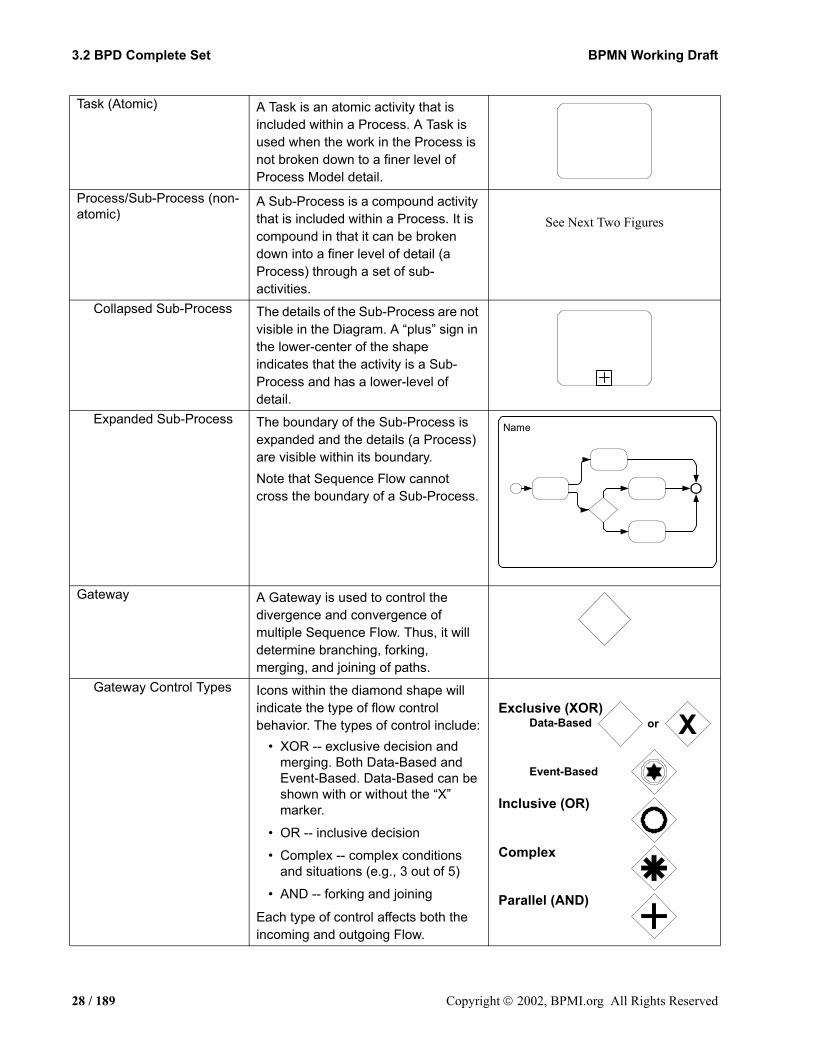
Task (Atomic) A Task is an atomic activity that is included within a Process. A Task is used when the work in the Process is not broken down to a finer level of Process Model detail.
Process/Sub-Process (non-atomic)
A Sub-Process is a compound activity that is included within a Process. It is compound in that it can be broken down into a finer level of detail (a Process) through a set of sub-activities.
See Next Two Figures
Collapsed Sub-Process The details of the Sub-Process are not visible in the Diagram. A “plus” sign in the lower-center of the shape indicates that the activity is a Sub-Process and has a lower-level of detail.
Expanded Sub-Process The boundary of the Sub-Process is expanded and the details (a Process) are visible within its boundary.Note that Sequence Flow cannot cross the boundary of a Sub-Process.
Gateway A Gateway is used to control the divergence and convergence of multiple Sequence Flow. Thus, it will determine branching, forking, merging, and joining of paths.
Gateway Control Types Icons within the diamond shape will indicate the type of flow control behavior. The types of control include:
• XOR -- exclusive decision and merging. Both Data-Based and Event-Based. Data-Based can be shown with or without the “X” marker.
• OR -- inclusive decision
• Complex -- complex conditions and situations (e.g., 3 out of 5)
• AND -- forking and joining
Each type of control affects both the incoming and outgoing Flow.
Name
Parallel (AND)
Exclusive (XOR)
Complex
Data-Based
Event-Based
Inclusive (OR)
Xor
28 / 189 Copyright 2002, BPMI.org All Rights Reserved

BPMN Working Draft 3. Business Process Diagrams
Sequence Flow A Sequence Flow is used to show the order that activities will be performed in a Process.
See next seven figures
Normal flow Normal Sequence Flow refers to the flow that originates from a Start Event and continues through activities via alternative and parallel paths until it ends at an End Event.
Uncontrolled flow Uncontrolled flow refers to flow that is not affected by any conditions or does not pass through a Gateway. The simplest example of this is a single Sequence Flow connecting two activities. This can also apply to multiple Sequence Flow that converge on or diverge from an activity. For each uncontrolled Sequence Flow a “Token” will flow from the source object to the target object.
Conditional flow Sequence Flow can have condition expressions that are evaluated at runtime to determine whether or not the flow will be used. If the conditional flow is outgoing from an activity, then the Sequence Flow will have a mini-diamond at the beginning of the line (see figure to the right). If the conditional flow is outgoing from a Gateway, then the line will not have a mini-diamond (see figure in the row above).
Default flow For Data-Based Exclusive Decisions, one type of flow is the Default condition flow. This flow will be used only if all the other outgoing conditional flow is not true at runtime. These Sequence Flow will have a diagonal slash will be added to the beginning of the line (see the figure to the right). Note that it is an Open Issue whether Default Conditions will be used for Inclusive Decision situations.
Name, Condition,Code, or Message
Name, Condition,Code, or Message
Name, Condition, or Code
Name orDefault
Copyright 2003, BPMI.org All Rights Reserved 29 / 189

3.2 BPD Complete Set BPMN Working Draft
Exception flow Exception flow occurs outside the normal flow of the Process and is based upon an Intermediate Event that occurs during the performance of the Process.
Message Flow A Message Flow is used to show the flow of messages between two entities that are prepared to send and receive them. In BPMN, two separate Pools in the Diagram will represent the two entities.
Compensation Association Compensation Association occurs outside the normal flow of the Process and is based upon an event (a Cancel Intermediate Event) that is triggered through the failure of a Transaction or a Compensate Event. The target of the Association must be marked as a Compensation Activity.
Data Object Data Objects are considered artifacts because they do not have any direct affect on the Sequence Flow or Message Flow of the Process, but they do provide information about what the Process does.
Fork (AND-Split) BPMN uses the term “fork” to refer to the dividing of a path into two or more parallel paths (also known as an AND-Split). It is a place in the Process where activities can be performed concurrently, rather than serially.There are two options: Multiple Outgoing Sequence Flow can be used (see figure top-right). This represents “uncontrolled” flow is the preferred method for most situations.A Parallel (AND) Gateway can be used (see figure bottom-right). This will be used rarely, usually in combination with other Gateways.
ExceptionFlow
Name orMessage
CompensationAssociation
Name
30 / 189 Copyright 2002, BPMI.org All Rights Reserved
BPMN Working Draft 3. Business Process Diagrams
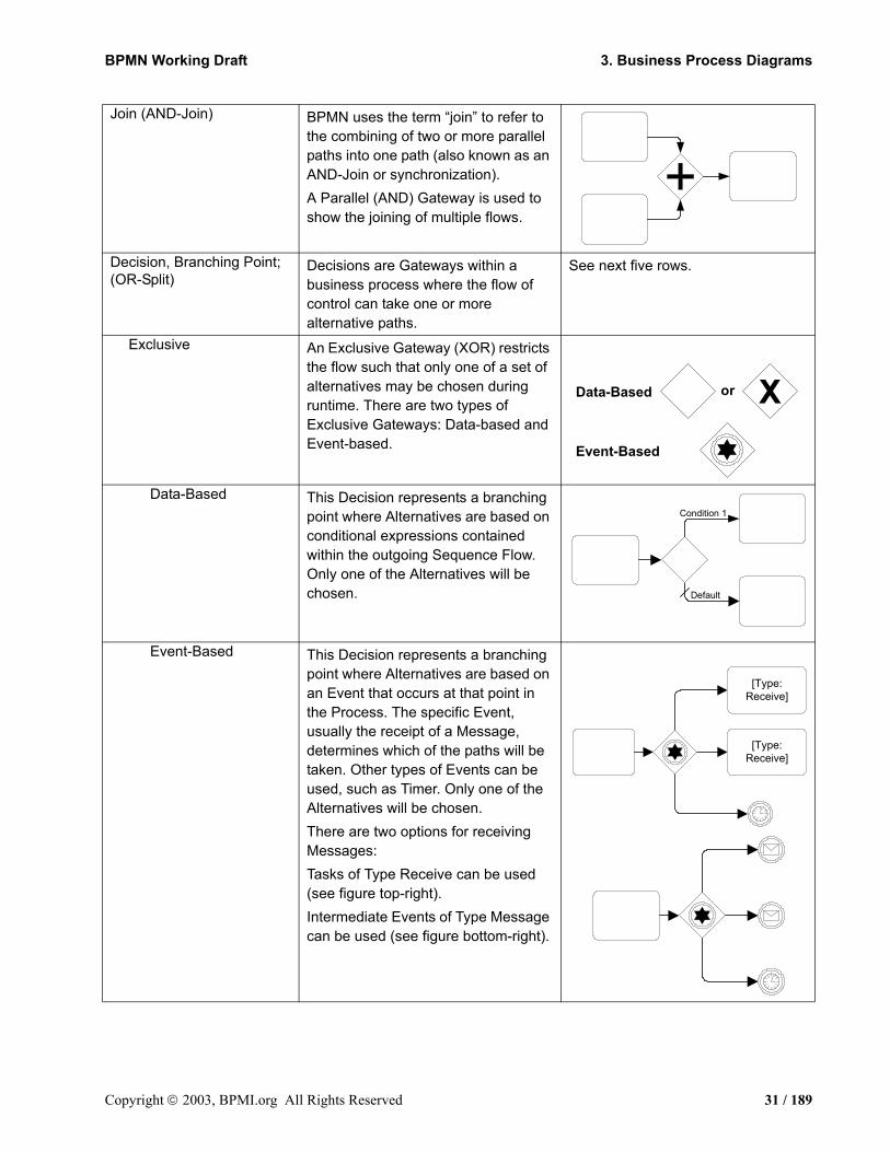
Join (AND-Join) BPMN uses the term “join” to refer to the combining of two or more parallel paths into one path (also known as an AND-Join or synchronization).A Parallel (AND) Gateway is used to show the joining of multiple flows.
Decision, Branching Point; (OR-Split)
Decisions are Gateways within a business process where the flow of control can take one or more alternative paths.
See next five rows.
Exclusive An Exclusive Gateway (XOR) restricts the flow such that only one of a set of alternatives may be chosen during runtime. There are two types of Exclusive Gateways: Data-based and Event-based.
Data-Based This Decision represents a branching point where Alternatives are based on conditional expressions contained within the outgoing Sequence Flow. Only one of the Alternatives will be chosen.
Event-Based This Decision represents a branching point where Alternatives are based on an Event that occurs at that point in the Process. The specific Event, usually the receipt of a Message, determines which of the paths will be taken. Other types of Events can be used, such as Timer. Only one of the Alternatives will be chosen.There are two options for receiving Messages: Tasks of Type Receive can be used (see figure top-right). Intermediate Events of Type Message can be used (see figure bottom-right).
Data-Based
Event-Based
Xor
Default
Condition 1
[Type:Receive]
[Type:Receive]
Copyright 2003, BPMI.org All Rights Reserved 31 / 189
3.2 BPD Complete Set BPMN Working Draft
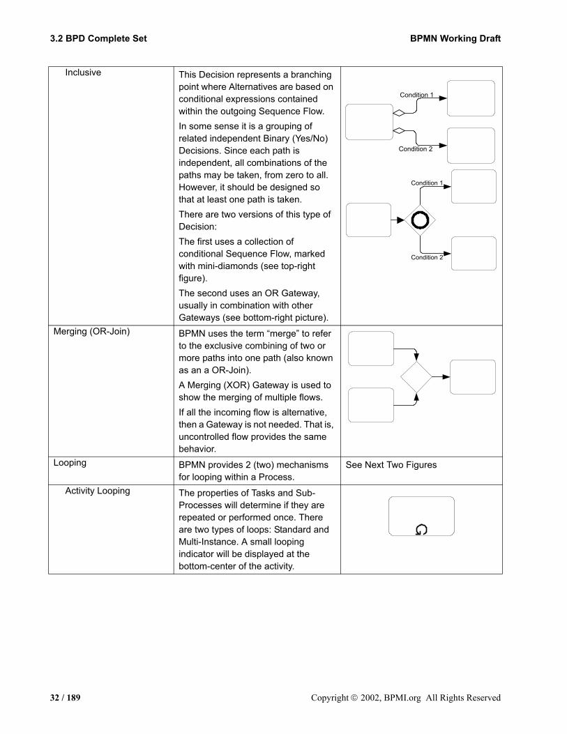
Inclusive This Decision represents a branching point where Alternatives are based on conditional expressions contained within the outgoing Sequence Flow.In some sense it is a grouping of related independent Binary (Yes/No) Decisions. Since each path is independent, all combinations of the paths may be taken, from zero to all. However, it should be designed so that at least one path is taken.There are two versions of this type of Decision:The first uses a collection of conditional Sequence Flow, marked with mini-diamonds (see top-right figure). The second uses an OR Gateway, usually in combination with other Gateways (see bottom-right picture).
Merging (OR-Join) BPMN uses the term “merge” to refer to the exclusive combining of two or more paths into one path (also known as an a OR-Join).A Merging (XOR) Gateway is used to show the merging of multiple flows.If all the incoming flow is alternative, then a Gateway is not needed. That is, uncontrolled flow provides the same behavior.
Looping BPMN provides 2 (two) mechanisms for looping within a Process.
See Next Two Figures
Activity Looping The properties of Tasks and Sub-Processes will determine if they are repeated or performed once. There are two types of loops: Standard and Multi-Instance. A small looping indicator will be displayed at the bottom-center of the activity.
Condition 1
Condition 2
Condition 2
Condition 1
32 / 189 Copyright 2002, BPMI.org All Rights Reserved
BPMN Working Draft 3. Business Process Diagrams
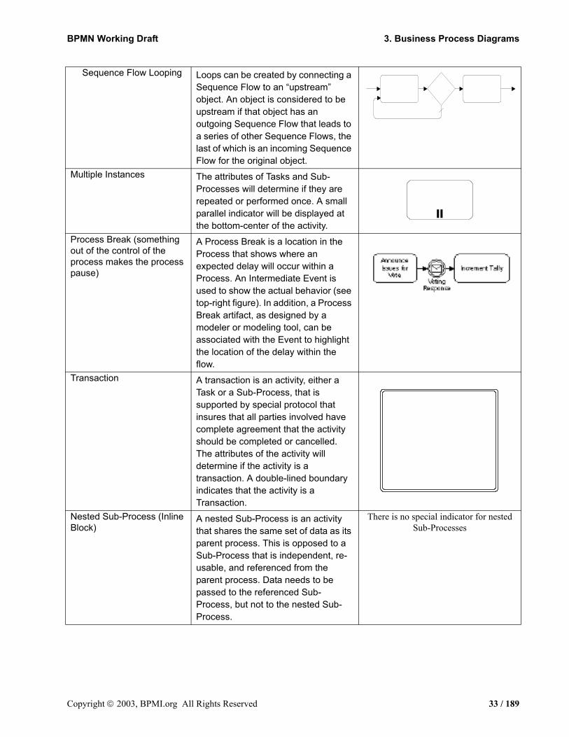
Sequence Flow Looping Loops can be created by connecting a Sequence Flow to an “upstream” object. An object is considered to be upstream if that object has an outgoing Sequence Flow that leads to a series of other Sequence Flows, the last of which is an incoming Sequence Flow for the original object.
Multiple Instances The attributes of Tasks and Sub-Processes will determine if they are repeated or performed once. A small parallel indicator will be displayed at the bottom-center of the activity.
Process Break (something out of the control of the process makes the process pause)
A Process Break is a location in the Process that shows where an expected delay will occur within a Process. An Intermediate Event is used to show the actual behavior (see top-right figure). In addition, a Process Break artifact, as designed by a modeler or modeling tool, can be associated with the Event to highlight the location of the delay within the flow.
Transaction A transaction is an activity, either a Task or a Sub-Process, that is supported by special protocol that insures that all parties involved have complete agreement that the activity should be completed or cancelled. The attributes of the activity will determine if the activity is a transaction. A double-lined boundary indicates that the activity is a Transaction.
Nested Sub-Process (Inline Block)
A nested Sub-Process is an activity that shares the same set of data as its parent process. This is opposed to a Sub-Process that is independent, re-usable, and referenced from the parent process. Data needs to be passed to the referenced Sub-Process, but not to the nested Sub-Process.
There is no special indicator for nested Sub-Processes
=
Copyright 2003, BPMI.org All Rights Reserved 33 / 189
3.3 Use of Text, Color, Size, and Lines in a Diagram BPMN Working Draft
Table 2 BPD Complete Element Set
3.3 Use of Text, Color, Size, and Lines in a DiagramText Annotation objects can be used by the modeler to display additional information about a Process or attributes of the objects within the Process.
Flow objects and Flows MAY have labels (e.g., its name and/or other attributes) placed inside the shape, or above or below the shape, in any direction or location, depending on the preference of the modeler or modeling tool vendor.
The fills that are used to for the graphical elements MUST be white or clear.
The notation MAY be extended to use other fill colors to suit the purpose of the modeler or tool (e.g., to highlight the value of an object attribute).
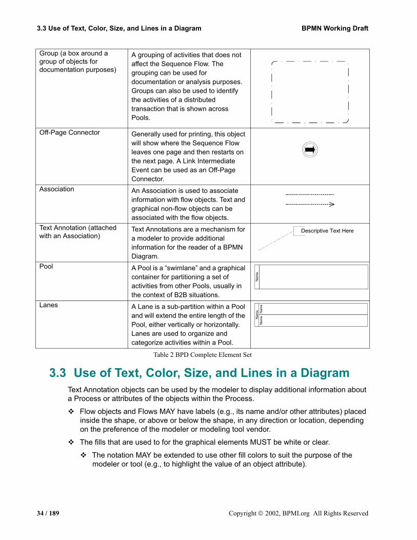
Group (a box around a group of objects for documentation purposes)
A grouping of activities that does not affect the Sequence Flow. The grouping can be used for documentation or analysis purposes. Groups can also be used to identify the activities of a distributed transaction that is shown across Pools.
Off-Page Connector Generally used for printing, this object will show where the Sequence Flow leaves one page and then restarts on the next page. A Link Intermediate Event can be used as an Off-Page Connector.
Association An Association is used to associate information with flow objects. Text and graphical non-flow objects can be associated with the flow objects.
Text Annotation (attached with an Association)
Text Annotations are a mechanism for a modeler to provide additional information for the reader of a BPMN Diagram.
Pool A Pool is a “swimlane” and a graphical container for partitioning a set of activities from other Pools, usually in the context of B2B situations.
Lanes A Lane is a sub-partition within a Pool and will extend the entire length of the Pool, either vertically or horizontally. Lanes are used to organize and categorize activities within a Pool.
Descriptive Text Here
Nam
eN
ame Nam
eN
ame
34 / 189 Copyright 2002, BPMI.org All Rights Reserved

BPMN Working Draft 3. Business Process Diagrams3.4.1 Sequence Flow Rules
Flow objects and markers MAY be of any size that suits the purposes of the modeler or modeling tool.
The lines that are used to draw the graphical elements MUST be black.
The notation MAY be extended to use other line colors to suit the purpose of the modeler or tool (e.g., to highlight the value of an object attribute).
The notation MAY be extended to use other line styles to suit the purpose of the modeler or tool (e.g., to highlight the value of an object attribute) with the condition that the line style MAY NOT conflict with any current BPMN defined line style.
3.4 Flow Object Connection RulesAn incoming Sequence Flow can connect to any location on a flow object (left, right, top, or bottom). Likewise, an outgoing Sequence Flow can connect from any location on a flow object (left, right, top, or bottom). Message Flows also have this capability. BPMN allows this flexibility, however, we also recommend that modelers use judgment or best practices in how flow objects should be connected so that readers of the Diagrams will find the behavior clear and easy to follow. This is even more important when a Diagram contains Sequence Flows and Message Flows. In these situations it is best to pick a direction of Sequence Flow, either left to right or top to bottom, and then direct the Message Flow at a 90° angle to the Sequence Flow. The resulting Diagrams will be much easier to understand.
3.4.1 Sequence Flow RulesTable 3 displays the BPMN flow objects and shows how these objects can connect to one another through Sequence Flows. The symbol indicates that the object listed in the row can connect to the object listed in the column. The quantity of connections into and out of an object is subject to various configuration dependencies are not specified here. Refer to the sections in the next chapter for each individual object for more detailed information on the appropriate connection rules. Note that if a sub-process has been expanded within a Diagram, the objects within the sub-process cannot be connected to objects outside of the sub-process. Nor can Sequence Flows cross a Pool boundary.
Copyright 2003, BPMI.org All Rights Reserved 35 / 189

3.4 Flow Object Connection Rules BPMN Working Draft3.4.2 Message Flow Rules
Table 3 Sequence Flow Connection Rules
Note: Only those objects that can have incoming and/or outgoing Sequence Flow are shown in the table. Thus, Pool, Lane, Data Object, and Text Annotation are not listed in the table.
3.4.2 Message Flow RulesTable 4 displays the BPMN modeling objects and shows how these objects can connect to one another through Message Flows. The symbol indicates that the object listed in the row can connect to the object listed in the column. The quantity of connections into and out of an object is subject to various configuration dependencies are not specified here. Refer to the sections in the next chapter for each individual object for more detailed information on the appropriate connection rules. Note that Message Flows cannot connect to objects that are within the same Participant Lane boundary.
From\To+
Name Name
+Name
Name
36 / 189 Copyright 2002, BPMI.org All Rights Reserved
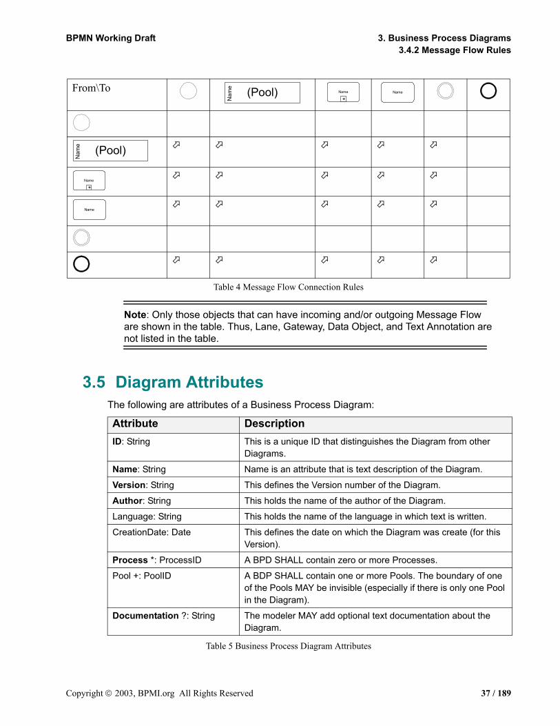
BPMN Working Draft 3. Business Process Diagrams3.4.2 Message Flow Rules
Table 4 Message Flow Connection Rules
Note: Only those objects that can have incoming and/or outgoing Message Flow are shown in the table. Thus, Lane, Gateway, Data Object, and Text Annotation are not listed in the table.
3.5 Diagram AttributesThe following are attributes of a Business Process Diagram:
Table 5 Business Process Diagram Attributes
From\To
Attribute DescriptionID: String This is a unique ID that distinguishes the Diagram from other
Diagrams.
Name: String Name is an attribute that is text description of the Diagram.
Version: String This defines the Version number of the Diagram.
Author: String This holds the name of the author of the Diagram.
Language: String This holds the name of the language in which text is written.
CreationDate: Date This defines the date on which the Diagram was create (for this Version).
Process *: ProcessID A BPD SHALL contain zero or more Processes.
Pool +: PoolID A BDP SHALL contain one or more Pools. The boundary of one of the Pools MAY be invisible (especially if there is only one Pool in the Diagram).
Documentation ?: String The modeler MAY add optional text documentation about the Diagram.
Nam
e (Pool)+
Name Name
Nam
e (Pool)
+Name
Name
Copyright 2003, BPMI.org All Rights Reserved 37 / 189

3.5 Diagram Attributes BPMN Working Draft3.4.2 Message Flow Rules
38 / 189 Copyright 2002, BPMI.org All Rights Reserved

BPMN Working Draft
4. Business Process Diagram Graphical Objects
This section details the graphical representation and the semantics of the behavior of Business Process Diagram graphical elements. Refer to the section entitled “Mapping to XML Languages” on page 153 for more information about how these elements map to execution languages.
4.1 Common BPD Object AttributesThe following table displays a set of common attributes for BPMN objects (specifically Events, Activities, and Gateways):
Table 6 Common Object Attributes
4.2 EventsAn Event is something that “happens” during the course of a business process. These Events affect the flow of the Process and usually have a cause or an impact. The term “event” is general enough to cover many things in a business process. The start of an activity, the end of an activity, the change of state of a document, a message that arrives, etc., all could be considered events. However, BPMN has restricted the use of events to include only those types of events that will affect the sequence or timing of activities of a process. BPMN further categorizes Events into three main types: Start, Intermediate, and End.
Start and Intermediate Events have “Triggers” that define the cause for the event. There are multiple ways that these events can be triggered (refer to the section entitled “Start Event Triggers” on page 42 and “Intermediate Event Triggers” on page 49). End Events may define a “Result” that is a consequence of a Sequence Flow ending. There are multiple types of Results that can be defined (refer to the section entitled “End Event Results” on page 46).
Attributes DescriptionId: String This is a unique ID that identifies the object from other objects
within the Diagram.
Name: String Name is an attribute that is text description of the object.Assign *: Expression Zero or more assignments MAY be made for the object. The
expressions SHALL be evaluated when the flow of the Process (the Token) arrives at the object.
Pool: PoolName A PoolName MUST be added to the object to identify its location.Lane *: LaneName If the Pool has more than one Lane, then a LaneName MUST be
added. There MAY be multiple Lanes listed if the Lanes are organized in matrix or overlap in a non-nested manner.
Documentation ?: String The modeler MAY add optional text documentation about the object.
Copyright 2003, BPMI.org All Rights Reserved 39 / 189
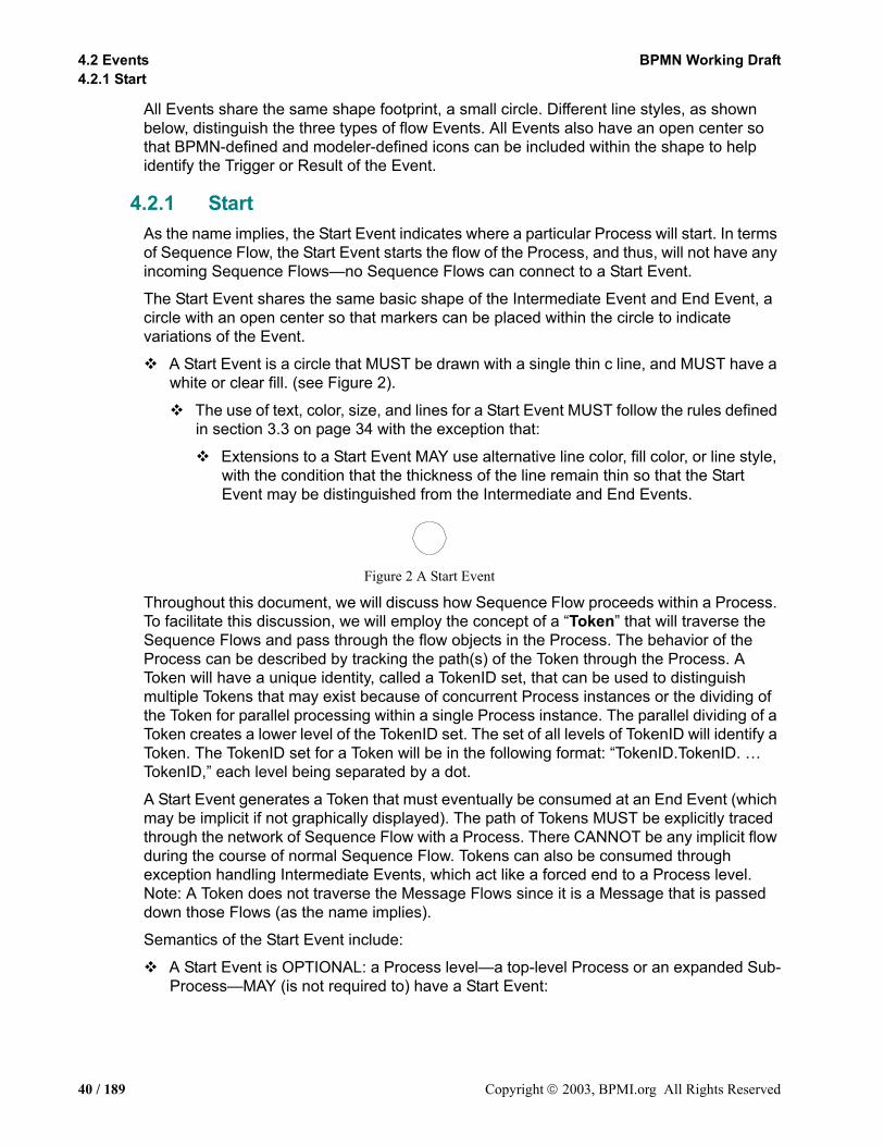
4.2 Events BPMN Working Draft4.2.1 Start
All Events share the same shape footprint, a small circle. Different line styles, as shown below, distinguish the three types of flow Events. All Events also have an open center so that BPMN-defined and modeler-defined icons can be included within the shape to help identify the Trigger or Result of the Event.
4.2.1 StartAs the name implies, the Start Event indicates where a particular Process will start. In terms of Sequence Flow, the Start Event starts the flow of the Process, and thus, will not have any incoming Sequence Flows—no Sequence Flows can connect to a Start Event.
The Start Event shares the same basic shape of the Intermediate Event and End Event, a circle with an open center so that markers can be placed within the circle to indicate variations of the Event.
A Start Event is a circle that MUST be drawn with a single thin c line, and MUST have a white or clear fill. (see Figure 2).
The use of text, color, size, and lines for a Start Event MUST follow the rules defined in section 3.3 on page 34 with the exception that:
Extensions to a Start Event MAY use alternative line color, fill color, or line style, with the condition that the thickness of the line remain thin so that the Start Event may be distinguished from the Intermediate and End Events.
Figure 2 A Start Event
Throughout this document, we will discuss how Sequence Flow proceeds within a Process. To facilitate this discussion, we will employ the concept of a “Token” that will traverse the Sequence Flows and pass through the flow objects in the Process. The behavior of the Process can be described by tracking the path(s) of the Token through the Process. A Token will have a unique identity, called a TokenID set, that can be used to distinguish multiple Tokens that may exist because of concurrent Process instances or the dividing of the Token for parallel processing within a single Process instance. The parallel dividing of a Token creates a lower level of the TokenID set. The set of all levels of TokenID will identify a Token. The TokenID set for a Token will be in the following format: “TokenID.TokenID. … TokenID,” each level being separated by a dot.
A Start Event generates a Token that must eventually be consumed at an End Event (which may be implicit if not graphically displayed). The path of Tokens MUST be explicitly traced through the network of Sequence Flow with a Process. There CANNOT be any implicit flow during the course of normal Sequence Flow. Tokens can also be consumed through exception handling Intermediate Events, which act like a forced end to a Process level. Note: A Token does not traverse the Message Flows since it is a Message that is passed down those Flows (as the name implies).
Semantics of the Start Event include:
A Start Event is OPTIONAL: a Process level—a top-level Process or an expanded Sub-Process—MAY (is not required to) have a Start Event:
40 / 189 Copyright 2003, BPMI.org All Rights Reserved
BPMN Working Draft 4. Business Process Diagram Graphical Objects4.2.1 Start
Note: A BPD may have more than one Process level (i.e., it can include Expanded Sub-Processes). The use of Start and End Events is independent for each level of the Diagram.
If a Process is complex and/or the starting conditions are not obvious, then it is RECOMMENDED that a Start Event be used.
If there is an End Event, then there MUST be at least one Start Event.
If the Start Event is used, then there SHALL NOT be other flow elements that do not have incoming Sequence Flow—all other flow objects MUST be a target of at least one Sequence Flow.
An exception to this are activities that are defined as being Compensation activities (have the Compensation Marker). Compensation activities SHALL NOT have any incoming Sequence Flow, even if there is a Start Event in the Process level. Refer to the section entitled “Compensation Association” on page 124 for more informations on Compensation activities.
An exception to this is the Intermediate Event, which MAY be without an incoming Sequence Flow (when attached to an activity boundary).
If the Start Event is not used, then all flow objects that do not have an incoming Sequence Flow (i.e., are not a target of a Sequence Flow) SHALL be instantiated when the Process is instantiated. There is an assumption that there is only one implicit Start Event, meaning that all the starting flow objects will start at the same time.
An exception to this are activities that are defined as being Compensation activities (have the Compensation Marker). Compensation Activities are not considered a part of the normal flow and SHALL NOT be instantiated when the Process is instantiated.
There MAY be multiple Start Events for a given Process level.
Each Start Event is an independent event. That is, a Process Instance SHALL be generated when the Start Event is triggered.
Note: The behavior of Process may be harder to understand if there are multiple Start Events. It is RECOMMENDED that this feature be used sparingly and that the modeler be aware that other readers of the Diagram may have difficulty understanding the intent of the Diagram.
When the trigger for a Start Event occurs, Tokens will be generated for each outgoing Sequence Flow from that event. The TokenID set for each of the Tokens will be established such that it can be identified that the Tokens are all from the same parallel Fork (AND-Split) and the number of Tokens in the group. These Tokens will begin their flow and not wait for any other Start Event to be triggered.
If there is a dependency for more than one Event to happen before a Process can start (e.g., two messages are required to start), then the Start Events must flow to the same activity within that Process. The attributes of the activity would specify when the activity
Copyright 2003, BPMI.org All Rights Reserved 41 / 189
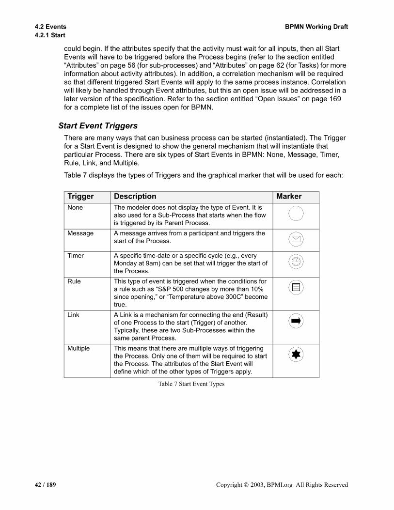
4.2 Events BPMN Working Draft4.2.1 Start
could begin. If the attributes specify that the activity must wait for all inputs, then all Start Events will have to be triggered before the Process begins (refer to the section entitled “Attributes” on page 56 (for sub-processes) and “Attributes” on page 62 (for Tasks) for more information about activity attributes). In addition, a correlation mechanism will be required so that different triggered Start Events will apply to the same process instance. Correlation will likely be handled through Event attributes, but this an open issue will be addressed in a later version of the specification. Refer to the section entitled “Open Issues” on page 169 for a complete list of the issues open for BPMN.
Start Event TriggersThere are many ways that can business process can be started (instantiated). The Trigger for a Start Event is designed to show the general mechanism that will instantiate that particular Process. There are six types of Start Events in BPMN: None, Message, Timer, Rule, Link, and Multiple.
Table 7 displays the types of Triggers and the graphical marker that will be used for each:
Table 7 Start Event Types
Trigger Description MarkerNone The modeler does not display the type of Event. It is
also used for a Sub-Process that starts when the flow is triggered by its Parent Process.
Message A message arrives from a participant and triggers the start of the Process.
Timer A specific time-date or a specific cycle (e.g., every Monday at 9am) can be set that will trigger the start of the Process.
Rule This type of event is triggered when the conditions for a rule such as “S&P 500 changes by more than 10% since opening,” or “Temperature above 300C” become true.
Link A Link is a mechanism for connecting the end (Result) of one Process to the start (Trigger) of another. Typically, these are two Sub-Processes within the same parent Process.
Multiple This means that there are multiple ways of triggering the Process. Only one of them will be required to start the Process. The attributes of the Start Event will define which of the other types of Triggers apply.
42 / 189 Copyright 2003, BPMI.org All Rights Reserved
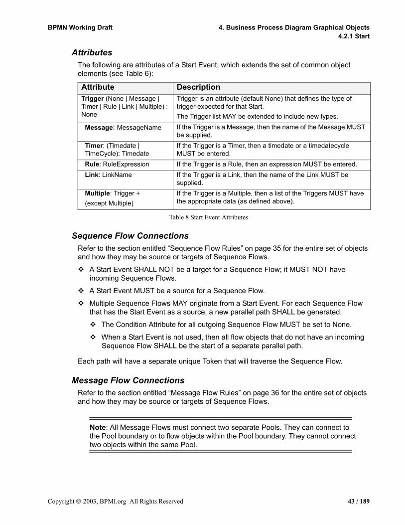
BPMN Working Draft 4. Business Process Diagram Graphical Objects4.2.1 Start
AttributesThe following are attributes of a Start Event, which extends the set of common object elements (see Table 6):
Table 8 Start Event Attributes
Sequence Flow ConnectionsRefer to the section entitled “Sequence Flow Rules” on page 35 for the entire set of objects and how they may be source or targets of Sequence Flows.
A Start Event SHALL NOT be a target for a Sequence Flow; it MUST NOT have incoming Sequence Flows.
A Start Event MUST be a source for a Sequence Flow.
Multiple Sequence Flows MAY originate from a Start Event. For each Sequence Flow that has the Start Event as a source, a new parallel path SHALL be generated.
The Condition Attribute for all outgoing Sequence Flow MUST be set to None.
When a Start Event is not used, then all flow objects that do not have an incoming Sequence Flow SHALL be the start of a separate parallel path.
Each path will have a separate unique Token that will traverse the Sequence Flow.
Message Flow ConnectionsRefer to the section entitled “Message Flow Rules” on page 36 for the entire set of objects and how they may be source or targets of Sequence Flows.
Note: All Message Flows must connect two separate Pools. They can connect to the Pool boundary or to flow objects within the Pool boundary. They cannot connect two objects within the same Pool.
Attribute DescriptionTrigger (None | Message | Timer | Rule | Link | Multiple) : None
Trigger is an attribute (default None) that defines the type of trigger expected for that Start.The Trigger list MAY be extended to include new types.
Message: MessageName If the Trigger is a Message, then the name of the Message MUST be supplied.
Timer: (Timedate | TimeCycle): Timedate
If the Trigger is a Timer, then a timedate or a timedatecycle MUST be entered.
Rule: RuleExpression If the Trigger is a Rule, then an expression MUST be entered. Link: LinkName If the Trigger is a Link, then the name of the Link MUST be
supplied.Multiple: Trigger +(except Multiple)
If the Trigger is a Multiple, then a list of the Triggers MUST have the appropriate data (as defined above).
Copyright 2003, BPMI.org All Rights Reserved 43 / 189

4.2 Events BPMN Working Draft4.2.2 End
A Start Event MAY be the target for Message Flows; it can have 0 (zero) or more incoming Message Flows. Each Message Flow arriving at a Start Event represents an instantiation mechanism (a Trigger) for the process. Only one of the Triggers is required to start a new Process.
The trigger attribute of the Start Event MUST be set to “Message” or “Multiple” if there are any incoming Message Flows.
A Start Event SHALL NOT be a source for a Message Flow; it MUST NOT have outgoing Message Flows.
4.2.2 EndAs the name implies, the End Event indicates where a process will end. In terms of Sequence Flow, the End Event ends the flow of the Process, and thus, will not have any outgoing Sequence Flows—no Sequence Flows can connect from an End Event.
The End Event shares the same basic shape of the Start Event and Intermediate Event, a circle with an open center so that markers can be placed within the circle to indicate variations of the Event.
An End Event is a circle that MUST be drawn with a single thick black line, and MUST a white or clear fill. (see Figure 3).
The use of text, color, size, and lines for an End Event MUST follow the rules defined in section 3.3 on page 34 with the exception that:
Extensions to an End Event MAY use alternative line color, fill color, or line style, with the condition that the thickness of the line remain thick so that the End Event may be distinguished from the Intermediate and Start Events.
Figure 3 End Event
To continue discussing how flow proceeds throughout the process, an End Event consumes a Token that had been generated from a Start Event within the same level of Process. If parallel Sequence Flows target the End Event, then the Tokens will be consumed as they arrive. All the Tokens that were generated from the Start Events or through forking during the Process must be consumed before the Process has been completed.
Semantics of the End Event include:
There MAY be multiple End Events within a single level of a process.
This shape is OPTIONAL: a given Process level—a top-level Process or an expanded Sub-Process—MAY (is not required to) have this shape:
If there is a Start Event, then there MUST be at least one End Event.
If an End Event is used, then there SHALL NOT be other flow elements that do not have any outgoing Sequence Flows—all other flow objects MUST be a source of at least one Sequence Flow.
44 / 189 Copyright 2003, BPMI.org All Rights Reserved

BPMN Working Draft 4. Business Process Diagram Graphical Objects4.2.2 End
An exception to this are activities that are defined as being Compensation activities (have the Compensation Marker). Compensation Activities SHALL NOT have any outgoing Sequence Flow, even if there is an End Event in the Process level. Refer to the section entitled “Compensation Association” on page 124 for more information on Compensation activities.
If the End Event is not used, then all flow objects that do not have any outgoing Sequence Flows (i.e., are not a source of a Sequence Flow) mark the end of the Process. However, the process SHALL NOT end until all parallel paths have completed.
An exception to this are activities that are defined as being Compensation activities (have the Compensation Marker). Compensation Activities are not considered a part of the normal flow and SHALL NOT mark the end of the Process.
Note: A BPD may have more than one Process level (i.e., it can include Expanded Sub-Processes). The use of Start and End Events is independent for each level of the Diagram.
A Token entering the path-ending flow objects will be consumed when the processing performed by those objects are completed (when the path has completed). When all Tokens for a given instance of the Process are consumed, then the Process will reach a state of being completed. However, a Process may be given attributes to control how Tokens moves back up to a higher-level Process. This is an open issue. Refer to the section entitled “Open Issues” on page 169 for a complete list of the issues open for BPMN.
Copyright 2003, BPMI.org All Rights Reserved 45 / 189

4.2 Events BPMN Working Draft4.2.2 End
End Event ResultsA BPMN modeler can define the consequence of reaching an End Event. This will be referred to as the End Event Result.
Table 9 displays the types of Results and the graphical marker that will be used for each:
Table 9 End Event Types
Result Description MarkerNone The modeler does not display the type of Event. It is
also used for a Sub-Process that end and the flow goes back to its Parent Process.
Message This type of End indicates that a message is sent to a participant at the conclusion of the Process.
Exception This type of End indicates that a named Error should be generated. This Error will be caught by an Intermediate Event within the Event Context.
Cancel This type of End is used within a Transaction Sub-
Process. It will indicate that the Transaction should be cancelled and will trigger a Cancel Intermediate Event attached to the Sub-Process boundary. In addition, it will indicate that a Transaction Protocol Cancel message should be sent to any Entities involved in the Transaction.
Compensation This type of End will indicate that a Compensation is necessary. This Compensation identifier will be used by an Intermediate Event when the Process is rolling back.
Link A Link is a mechanism for connecting the end (Result) of one Process to the start (Trigger) of another. Typically, these are two Sub-Processes within the same parent Process.
Terminate This type of End indicates that there is a fatal error and that all activities in the Process should be immediately ended. The Process is ended without compensation or event handling. Note that the marker for this Event is an Open Issue.
Multiple This means that there are multiple consequences of ending the Process. All of them will occur (e.g., there might be multiple messages sent). The attributes of the End Event will define which of the other types of Results apply.
46 / 189 Copyright 2003, BPMI.org All Rights Reserved
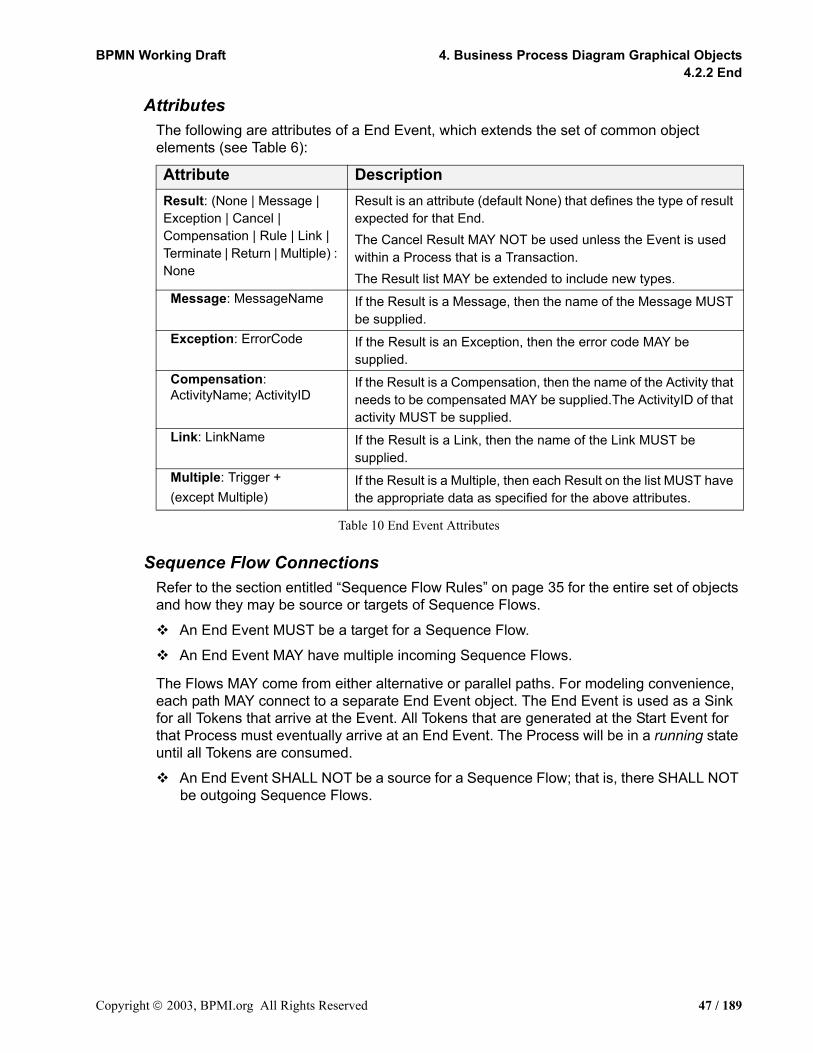
BPMN Working Draft 4. Business Process Diagram Graphical Objects4.2.2 End
AttributesThe following are attributes of a End Event, which extends the set of common object elements (see Table 6):
Table 10 End Event Attributes
Sequence Flow ConnectionsRefer to the section entitled “Sequence Flow Rules” on page 35 for the entire set of objects and how they may be source or targets of Sequence Flows.
An End Event MUST be a target for a Sequence Flow.
An End Event MAY have multiple incoming Sequence Flows.
The Flows MAY come from either alternative or parallel paths. For modeling convenience, each path MAY connect to a separate End Event object. The End Event is used as a Sink for all Tokens that arrive at the Event. All Tokens that are generated at the Start Event for that Process must eventually arrive at an End Event. The Process will be in a running state until all Tokens are consumed.
An End Event SHALL NOT be a source for a Sequence Flow; that is, there SHALL NOT be outgoing Sequence Flows.
Attribute DescriptionResult: (None | Message | Exception | Cancel | Compensation | Rule | Link | Terminate | Return | Multiple) : None
Result is an attribute (default None) that defines the type of result expected for that End.The Cancel Result MAY NOT be used unless the Event is used within a Process that is a Transaction.The Result list MAY be extended to include new types.
Message: MessageName If the Result is a Message, then the name of the Message MUST be supplied.
Exception: ErrorCode If the Result is an Exception, then the error code MAY be supplied.
Compensation: ActivityName; ActivityID
If the Result is a Compensation, then the name of the Activity that needs to be compensated MAY be supplied.The ActivityID of that activity MUST be supplied.
Link: LinkName If the Result is a Link, then the name of the Link MUST be supplied.
Multiple: Trigger +(except Multiple)
If the Result is a Multiple, then each Result on the list MUST have the appropriate data as specified for the above attributes.
Copyright 2003, BPMI.org All Rights Reserved 47 / 189

4.2 Events BPMN Working Draft4.2.3 Intermediate
Message Flow ConnectionsRefer to the section entitled “Message Flow Rules” on page 36 for the entire set of objects and how they may be source or targets of Sequence Flows.
Note: All Message Flows must connect two separate Pools. They can connect to the Pool boundary or to flow objects within the Pool boundary. They cannot connect two objects within the same Pool.
An End Event MUST NOT be the target for Message Flows; it can have no incoming Message Flows.
An End Event MAY be a source for a Message Flow; it can have one or more outgoing Message Flow.
4.2.3 IntermediateIntermediate Events occur between a Start Event and an End Event. This is an event that occurs after a Process has been started. It will affect the flow of the process, but will not start or (directly) terminate the process. Intermediate Events can be used to:
• Show where messages or delays are expected within the Process,
• Disrupt the normal flow through exception handling, or
• Show the extra work required for compensation.
The Intermediate Event shares the same basic shape of the Start Event and End Event, a circle with an open center so that markers can be placed within the circle to indicate variations of the Event.
An Intermediate Event is a circle that MUST drawn with a double thin black line, and MUST have a white or clear fill. (see Figure 3).
The use of text, color, size, and lines for an Intermediate Event MUST follow the rules defined in section 3.3 on page 34 with the exception that:
Extensions to an Intermediate Event MAY use alternative line color, fill color, or line style, with the condition that the thickness of the line remain double so that the Intermediate Event may be distinguished from the Start and End Events.
Figure 4 Intermediate Event
One use of Intermediate Events is to represent exception or compensation handling. This will be shown by placing the Intermediate Event on the boundary of a Task or Sub-Process (either collapsed or expanded). Figure 5 displays an example of an Intermediate Event attached to a Task. The Intermediate Event can be attached to any location of the activity boundary and the outgoing Sequence Flow can flow in any direction. However, in the interest of clarity of the Diagram, we recommend that the modeler choose a consistent location on the boundary. For example, if the Diagram orientation is horizontal, then the Intermediate Events can be attached to the bottom of the activity and the Sequence Flow directed down and then to the right. If the Diagram orientation is vertical, then the
48 / 189 Copyright 2003, BPMI.org All Rights Reserved

BPMN Working Draft 4. Business Process Diagram Graphical Objects4.2.3 Intermediate
Intermediate Events can be attached to the left or right side of the activity and the Sequence Flow directed to the left or right and then down.
Figure 5 Task with an Intermediate Event attached to its boundary
Intermediate Event TriggersThere are eight types of Intermediate Events in BPMN: Message, Timer, Exception, Compensation, Cancel, Rule, Link, and Multiple. These Event types indicate the different ways that a Process may be interrupted or delayed after it has started. Each type of Intermediate Event will have a different icon placed in the center of the Intermediate Event shape to distinguish one from another.
Review Status ofDiscussion
Moderate E-mailDiscussion
7 Days
Copyright 2003, BPMI.org All Rights Reserved 49 / 189
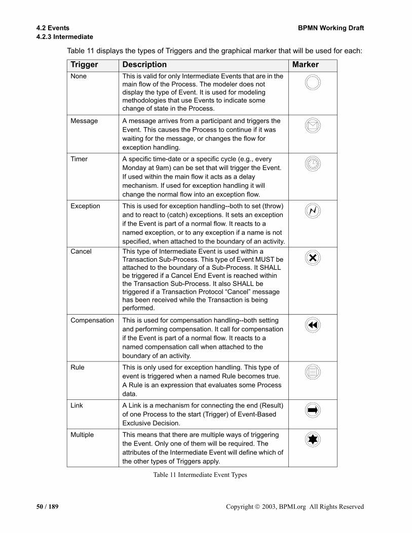
4.2 Events BPMN Working Draft4.2.3 Intermediate
Table 11 displays the types of Triggers and the graphical marker that will be used for each:
Table 11 Intermediate Event Types
Trigger Description MarkerNone This is valid for only Intermediate Events that are in the
main flow of the Process. The modeler does not display the type of Event. It is used for modeling methodologies that use Events to indicate some change of state in the Process.
Message A message arrives from a participant and triggers the Event. This causes the Process to continue if it was waiting for the message, or changes the flow for exception handling.
Timer A specific time-date or a specific cycle (e.g., every Monday at 9am) can be set that will trigger the Event. If used within the main flow it acts as a delay mechanism. If used for exception handling it will change the normal flow into an exception flow.
Exception This is used for exception handling--both to set (throw) and to react to (catch) exceptions. It sets an exception if the Event is part of a normal flow. It reacts to a named exception, or to any exception if a name is not specified, when attached to the boundary of an activity.
Cancel This type of Intermediate Event is used within a Transaction Sub-Process. This type of Event MUST be attached to the boundary of a Sub-Process. It SHALL be triggered if a Cancel End Event is reached within the Transaction Sub-Process. It also SHALL be triggered if a Transaction Protocol “Cancel” message has been received while the Transaction is being performed.
Compensation This is used for compensation handling--both setting and performing compensation. It call for compensation if the Event is part of a normal flow. It reacts to a named compensation call when attached to the boundary of an activity.
Rule This is only used for exception handling. This type of event is triggered when a named Rule becomes true. A Rule is an expression that evaluates some Process data.
Link A Link is a mechanism for connecting the end (Result) of one Process to the start (Trigger) of Event-Based Exclusive Decision.
Multiple This means that there are multiple ways of triggering the Event. Only one of them will be required. The attributes of the Intermediate Event will define which of the other types of Triggers apply.
50 / 189 Copyright 2003, BPMI.org All Rights Reserved

BPMN Working Draft 4. Business Process Diagram Graphical Objects4.2.3 Intermediate
AttributesThe following are attributes of an Intermediate Event, which extends the set of common object elements (see Table 6):
Table 12 Intermediate Event Attributes
Sequence Flow ConnectionsRefer to the section entitled “Sequence Flow Rules” on page 35 for the entire set of objects and how the may be source or targets of Sequence Flows.
Intermediate Events MAY be attached directly to the boundary of an Activity.
To be attached to the boundary of an Activity, an Intermediate Event MUST be one of the following Triggers: Message, Timer, Exception, Cancel, Compensation, Rule, and Multiple.
An Intermediate Event with a Cancel Trigger MAY be attached to an Activity boundary only if the Transaction attribute of the Activity is set to TRUE.
Attribute DescriptionTrigger: (None | Message | Timer | Exception | Cancel | Compensation | Rule | Multiple) : Message
Trigger is an attribute (default Message) that defines the type of trigger expected for that Intermediate Event. The None and Link Trigger MAY NOT be used when the Event is attached to the boundary of an Activity. The Multiple, Rule, and Cancel Triggers MAY NOT be used when the Event is part of the normal flow of the Process. The Cancel Trigger MAY NOT be used when the Event is attached to the boundary of an Activity that is not a Transaction or if the Event is not contained within a Process that is a Transaction.The Trigger list MAY be extended to include new types.
Message: MessageName If the Trigger is a Message, then the name of the Message must be supplied.
Timer: (Timedate | TimeCycle): Timedate
If the Trigger is a Timer, then a timedate or a timecycle must be entered.
Exception: (ErrorCode | None): ErrorCode
If the Trigger is an Exception, then the error code MAY be supplied. If there is no error code, then any Error SHALL trigger the Event. If there is an error code, then only an Error that matches the error code SHALL trigger the Event.
Compensation: ActivityName; ActivityID
If the Trigger is a Compensation, then the name of the Activity needs to be compensated MAY be supplied.The ActivityID of that activity MUST be supplied.
Rule: RuleName If the Trigger is a Rule, then an expression MUST be entered. Link: LinkName If the Trigger is a Link, then the name of the Link MUST be
supplied.Multiple: Trigger +(except Multiple and Compensation)
If the Trigger is a Multiple, then each Trigger on the list MUST have the appropriate data as specified for the above attributes.
Copyright 2003, BPMI.org All Rights Reserved 51 / 189

4.3 Activities BPMN Working Draft4.3.1 Process
If the Intermediate Event is attached to the boundary of an activity, then it MAY NOT be a target for a Sequence Flow; it cannot have an incoming Flow.
If the Intermediate Event is not attached to the boundary of an activity; that is, it is within normal flow, then it MAY be a target for a Sequence Flow. It MAY have one (and only one) incoming Flow.
Intermediate Event of the following types MAY be a target of a Sequence Flow: None, Message, Timer, Exception, Link, and Compensation.
An Intermediate Event with a Link Trigger MAY only be a target of a Sequence Flow if the source is an Event-Based Exclusive Gateway.
An Intermediate Event MUST be a source for a Sequence Flow; it can have one (and only one) outgoing Sequence Flow.
An exception to this: an Intermediate Event with a Compensation Trigger MUST NOT have an outgoing Sequence Flow (it MAY have an outgoing Association).
Message Flow ConnectionsRefer to the section entitled “Message Flow Rules” on page 36 for the entire set of objects and how the may be source or targets of Sequence Flows.
Note: All Message Flows must connect two separate Pools. They can connect to the Pool boundary or to flow objects within the Pool boundary. They cannot connect two objects within the same Pool.
An Intermediate Event of type Message MAY be the target for Message Flows; it can have one incoming Message Flows.
An Intermediate Event MAY NOT be a source for a Message Flow; it can have no outgoing Message Flows.
4.3 ActivitiesAn activity is work that is performed within a business process. An activity can be atomic or non-atomic (compound). The types of activities that are a part of a Process Model are: Process, Sub-Process, and Task. The following sections will detail how these activities are modeled with BPMN.
4.3.1 ProcessA Process is an activity performed within a company or organization. In BPMN a Process is depicted as a graph of flow objects, which are a set of other activities and the controls that sequence them. The concept of process is intrinsically hierarchical. Processes may be defined at any level from enterprise-wide processes to processes performed by a single person. Low-level processes may be grouped together to achieve a common business goal.
Note that BPMN defines the term Process fairly specifically and defines a Business Process more generically as a set of activities that are performed within an organization or across organizations. Thus a Business Process, as shown in a Business Process Diagram,
52 / 189 Copyright 2003, BPMI.org All Rights Reserved

BPMN Working Draft 4. Business Process Diagram Graphical Objects4.3.1 Process
may contain more than one separate Process. Each Process may have its own Sub-Processes and would be contained within a Pool (refer to the section entitled “Pool” on page 83). The individual Processes would be independent in terms of Sequence Flow, but could have Message Flow connecting them.
AttributesThe following are attributes of a Process, which extends the set of common object elements (see Table 6):
Table 13 Process Attributes
Attribute DescriptionProperty *: Modeler-defined Properties MAY be added to a Process. These
Properties are “local” to the Process. All Tasks, Sub-Process objects, and Sub-Processes that are embedded SHALL have access to these Properties. The fully delineated name of these properties are “<process name>.<property name>” (e.g., “Add Customer.Customer Name”). If a process is embedded within another Process, then the fully delineated name SHALL also be preceded by the Parent Process name for as many Parents there are until the top level Process.
Name: Each Property has a Name (e.g., name=”Customer Name”).Type: Each Property has a Type (e.g., type=”String”).
AdHoc: (True | False): False AdHoc is a Boolean attribute, which has a default of False. This specifies whether the Process is Ad Hoc or not. The activities within an Ad Hoc Process are not controlled or sequenced in a particular order, there performance is determined by the performers of the activities.
CompletionCondition: Expression
If the Process is Ad Hoc, then a Completion Condition MUST be included, which defines the conditions when the Process will end. The Ad Hoc marker SHALL be placed at the bottom center of the Process or the Sub-Process shape for Ad Hoc Processes.
PassThrough: (True | False): False
The definition of the PassThrough attribute is an open issue that will be handled in a later version of the specification. Refer to the section entitled “Open Issues” on page 169 for a complete list of the issues open for BPMN.
AssignTime: (Start | End): Start
Each Assignment Expression will have AssignTime.A value of Start means that the assignment SHALL occur at the start of the Process.A value of End means that the assignment SHALL occur at the end of the Process.
Copyright 2003, BPMI.org All Rights Reserved 53 / 189

4.3 Activities BPMN Working Draft4.3.2 Sub-Process
4.3.2 Sub-ProcessA Sub-Process is a compound activity in that it has detail that is defined as a flow of other activities. A Sub-Process is a graphical object within a Process Flow, but it also references another Process (either embedded or independent). A Sub-Process shares the same shape as the Task, which is a rectangle.
A Sub-Process is a rounded corner rectangle that MUST be drawn with a single thin black line, and MUST have a white or clear fill.
The use of text, color, size, and lines for a Sub-Process MUST follow the rules defined in section 3.3 on page 34.
The Sub-Process can be in a collapsed view that hides its details (see Figure 6) or a Sub-Process can be in an expanded view that shows its details within the view of the Process in which it is contained (see Figure 7). In the collapsed form, the Sub-Process object uses a marker to distinguish it as a Sub-Process, rather than a Task.
The Sub-Process marker MUST be a small square with a plus sign (+) inside. The square MUST be positioned at the bottom center of the shape.
Figure 6 Collapsed Sub-Process
Figure 7 Expanded Sub-Process
Expanded Sub-Process may be used for multiple purposes. They can be used to “flatten” a hierarchical process so that all detail can be shown at the same time. They are used to create a context for exception handling that applies to a group of activities (Refer to the section entitled “Exception Flow” on page 121 for more details). Compensations can be handled the similarly (Refer to the section entitled “Compensation Association” on page 124 for more details).
Expanded Sub-Process may be used as a mechanism for showing a group of parallel activities in a less-cluttered, more compact way. In Figure 8, activities “C” and “D” are enclosed in an unlabeled Expanded Sub-Process. These two activities will be performed in parallel. Notice that the Expanded Sub-Process does not include a Start Event or an End Event and the Sequence Flow to/from these Events. This usage of Expanded Sub-Processes for “parallel boxes” is the motivation for having Start and End Events being optional objects.
+
54 / 189 Copyright 2003, BPMI.org All Rights Reserved

BPMN Working Draft 4. Business Process Diagram Graphical Objects4.3.2 Sub-Process
Figure 8 Expanded Sub-Process used as a “parallel box”
BPMN specifies five types of standard markers for Sub-Processes. The (Collapsed) Sub-Process Marker, seen in Figure 6, can be combined with four other markers: a Loop Marker or a Parallel Marker, a Compensation Marker, and an Ad Hoc Marker. A Sub-Process may have one to three of these other markers, in all combinations except that Loop and Multiple Instance cannot be shown at the same time (see Figure 9).
The marker for a Sub-Process that loops MUST be a small line with an arrowhead that curls back upon itself.
The Loop Marker MAY be used in combination with any of the other markers except the Multiple Instance Marker.
The marker for a Sub-Process that has multiple instances MUST be a pair of vertical lines in parallel.
The Multiple Instance Marker MAY be used in combination with any of the other markers except the Loop Marker.
The marker for a Sub-Process that is Ad Hoc MUST be a “tilde” symbol.
The Ad-Hoc Marker MAY be used in combination with any of the other markers.
The marker for a Sub-Process that is used for compensation MUST be a pair of left facing triangles (like a tape player “rewind” button).
The Compensation Marker MAY be used in combination with any of the other markers.
All the markers that are present MUST be grouped and the whole group centered at the bottom of the shape.
Figure 9 Collapsed Sub-Process Markers
A
C
D
E
+ +=
Loop Multiple Instance Ad-Hoc
+ ~ +
Compensation
Copyright 2003, BPMI.org All Rights Reserved 55 / 189
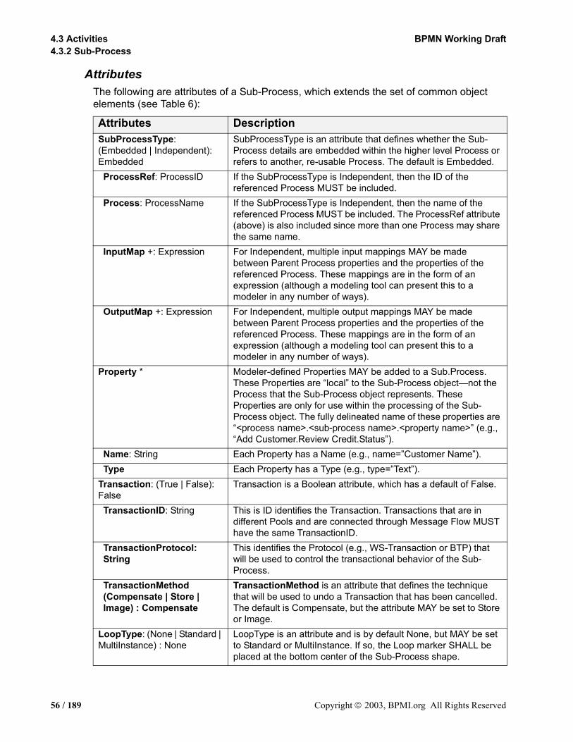
4.3 Activities BPMN Working Draft4.3.2 Sub-Process
AttributesThe following are attributes of a Sub-Process, which extends the set of common object elements (see Table 6):
Attributes DescriptionSubProcessType: (Embedded | Independent): Embedded
SubProcessType is an attribute that defines whether the Sub-Process details are embedded within the higher level Process or refers to another, re-usable Process. The default is Embedded.
ProcessRef: ProcessID If the SubProcessType is Independent, then the ID of the referenced Process MUST be included.
Process: ProcessName If the SubProcessType is Independent, then the name of the referenced Process MUST be included. The ProcessRef attribute (above) is also included since more than one Process may share the same name.
InputMap +: Expression For Independent, multiple input mappings MAY be made between Parent Process properties and the properties of the referenced Process. These mappings are in the form of an expression (although a modeling tool can present this to a modeler in any number of ways).
OutputMap +: Expression For Independent, multiple output mappings MAY be made between Parent Process properties and the properties of the referenced Process. These mappings are in the form of an expression (although a modeling tool can present this to a modeler in any number of ways).
Property * Modeler-defined Properties MAY be added to a Sub.Process. These Properties are “local” to the Sub-Process object—not the Process that the Sub-Process object represents. These Properties are only for use within the processing of the Sub-Process object. The fully delineated name of these properties are “<process name>.<sub-process name>.<property name>” (e.g., “Add Customer.Review Credit.Status”).
Name: String Each Property has a Name (e.g., name=”Customer Name”). Type Each Property has a Type (e.g., type=”Text”).
Transaction: (True | False): False
Transaction is a Boolean attribute, which has a default of False.
TransactionID: String This is ID identifies the Transaction. Transactions that are in different Pools and are connected through Message Flow MUST have the same TransactionID.
TransactionProtocol: String
This identifies the Protocol (e.g., WS-Transaction or BTP) that will be used to control the transactional behavior of the Sub-Process.
TransactionMethod (Compensate | Store | Image) : Compensate
TransactionMethod is an attribute that defines the technique that will be used to undo a Transaction that has been cancelled. The default is Compensate, but the attribute MAY be set to Store or Image.
LoopType: (None | Standard | MultiInstance) : None
LoopType is an attribute and is by default None, but MAY be set to Standard or MultiInstance. If so, the Loop marker SHALL be placed at the bottom center of the Sub-Process shape.
56 / 189 Copyright 2003, BPMI.org All Rights Reserved

BPMN Working Draft 4. Business Process Diagram Graphical Objects4.3.2 Sub-Process
Table 14 Sub-Process Attributes
LoopCondition: Expression Standard and MultiInstance Loops MUST have an expression to be evaluated, plus the timing when the expression SHALL be evaluated.
Counter: Number The Counter attribute is used at runtime to count the number of loops.
Maximum ?: Number For Standard Loops, the Maximum an optional attribute that provides is a simple way to add a cap to the number of loops. This SHALL be added to the expression when mapped to BPEL4WS.
TestTime: (Before | After) : After
This applies to only Standard Loops. The expressions evaluated Before the Sub-Process begins are while loops and expressions evaluated After the Sub-Process finishes are while loops for BPEL4WS.
InstanceGeneration: (Serial | Parallel) : Serial
This applies to only MultiInstance Loops. The InstanceGeneration attribute defines whether the loop instances will be performed serially or in parallel. A serial MultiInstance is a more traditional loop. A parallel MultiInstance is equivalent to multi-instance specifications that other notations, such as UML Activity Diagrams use. If set to Parallel, the Parallel marker SHALL replace the Loop Marker at the bottom center of the Sub-Process shape.
LoopFlowCondition: (One | All | Complex): All
This applies only to Parallel MultiInstance Loops. It is equivalent to using a Gateway to control the flow past a set of parallel paths.A LoopFlowCondition of One is the same as a Joining Gateway and means that the Token SHALL continue past the Sub-Process after only one of the Sub-Process instances has completed. The Sub-Process will continue its other instances, but additional Tokens SHALL NOT be passed from the Sub-Process. A LoopFlowCondition of All is the same as uncontrolled flow (no Gateway) and means that all Sub-Process instances SHALL generate a token that will continue when that instance is completed. A LoopFlowCondition of Complex is the same as a Complex Gateway. The ComplexExpression Attribute will determine the Token flow.
Complex ?: Expression A complex Loop Flow Condition MAY be set by the modeler. This will consist of an expression that MAY reference Process data. The expression SHALL determine when and how many Tokens will continue past the Sub-Process.
AssignTime: (Start | End): Start
(the Assign attribute is part of the set of common BPD object attributes. Refer to Table 6 for the complete list of common attributes)Each Assignment Expression will have AssignTime.A value of Start means that the assignment SHALL occur at the start of the Sub-Process. A value of End means that the assignment SHALL occur at the end of the Sub-Process.
Attributes Description
Copyright 2003, BPMI.org All Rights Reserved 57 / 189

4.3 Activities BPMN Working Draft4.3.2 Sub-Process
Sub-Process Behavior as a TransactionA Sub-Process, either collapse or expanded, can be set as being a Transaction, which will have a special behavior that is controlled through a transaction protocol (such as BTP or WS-Transaction). The boundary of the activity will be double-lined to indicate that it is a Transaction (see Figure 10).
Figure 10 An Example of a Transaction Expanded Sub-Process
There are three basic outcomes of a Transaction:
• Successful completion: this will be shown as a normal Sequence Flow that leaves the Sub-Process.
• Failed completion (Cancel): When a Transaction is cancelled, then the activities inside the Transaction will be subjected to the cancellation actions, which could include rolling back the process and compensation for specific activities. Note that other mechanisms for interrupting a Sub-Process will not cause Compensation (e.g., Exception, Timer, and anything for a non-Transaction activity). A Cancel Intermediate Event, attached to the boundary of the activity, will direct the flow after the Transaction has been rolled back and all compensation has been completed. The Cancel Intermediate Event can only be
Bookings
Book Flight
Book Hotel
SendUnavailability
Notice
Cancel Flight
Send HotelCancellation
Transaction
SuccessfulBookings
FailedBookings
Exceptions(Hazards)
ChargeBuyer
Handle throughCustomer Service
58 / 189 Copyright 2003, BPMI.org All Rights Reserved
BPMN Working Draft 4. Business Process Diagram Graphical Objects4.3.2 Sub-Process
used when attached to the boundary of a Transaction activity. It cannot be used in any normal flow and cannot be attached to a non-Transaction activity. There are two mechanisms that can signal the cancellation of a Transaction:
• A Cancel End Event is reached within the Transaction Sub-Process. A Cancel End Event can only be used within a Sub-Process that is set to a Transaction.
• A Cancel Message can be received via the Transaction Protocol that is supporting the execution of the Sub-Process.
• Hazard: This means that something went terribly wrong and that a normal success or cancel is not possible. We are using an Exception to show Hazards. When a Hazard happens, the activity is interrupted (without Compensation) and the flow will continue from the Exception Intermediate Event.
The behavior at the end of a successful Transaction Sub-Process is slightly different than that of a normal Sub-Process. When each path of the Transaction Sub-Process reaches a non-Cancel End Event(s), the flow does not immediately move back up to the higher-level Parent Process, as does a normal Sub-Process. First, the transaction protocol must verify that all the participants have successfully completed their end of the Transaction. Most of the time this will be true and the flow will then move up to the higher-level Process. But it is possible that one of the participants may end up with a problem that causes a Cancel or a Hazard. In this case, the flow will then move to the appropriate Intermediate Event, even though it had apparently finished successfully.
Note: The exact behavior and notation for defining Transactions is still an Open Issue. Refer to the section entitled “Open Issues” on page 169 for a complete list of the issues open for BPMN.
Sequence Flow ConnectionsRefer to the section entitled “Sequence Flow Rules” on page 35 for the entire set of objects and how the may be source or targets of Sequence Flows.
A Sub-Process MAY be a target for a Sequence Flow; it can have multiple incoming Flows. Incoming Flow MAY be from an alternative path and/or a parallel paths.
Note: If the Sub-Process has multiple incoming Sequence Flows, then this is considered uncontrolled flow. This means that when a Token arrives from one of the Paths, the Sub-Process will be instantiated. It will not wait for the arrival of Tokens from the other paths. If another Token arrives from the same path or another path, then a separate instance of the Sub-Process will be created. If the flow needs to be controlled, then the flow should converge on a Gateway that precedes the Sub-Process (Refer to the section entitled “Gateways” on page 64 for more information on Gateways).
If the Sub-Process does not have an incoming Sequence Flow, and there is no Start Event for the Process, then the Sub-Process MUST be instantiated when the process is instantiated.
Copyright 2003, BPMI.org All Rights Reserved 59 / 189
4.3 Activities BPMN Working Draft4.3.3 Task
An exception to this are Sub-Processes that are defined as being Compensation activities (have the Compensation Marker). Compensation Sub-Processes are not considered a part of the normal flow and SHALL NOT be instantiated when the Process is instantiated.
A Sub-Process MAY be a source for a Sequence Flow; it can have multiple outgoing Flows. If there are multiple outgoing Sequence Flows, then this means that a separate parallel path is being created for each Flow.
Tokens will be generated for each outgoing Sequence Flow from Sub-Process. The TokenIDs for each of the Tokens will be set such that it can be identified that the Tokens are all from the same parallel Fork (AND-Split) and the number of Tokens in the group
If the Sub-Process does not have an outgoing Sequence Flow, and there is no End Event for the Process, then the Sub-Process marks the end of one or more paths in the Process. When the Sub-Process ends and there are no other parallel paths active, then the Process MUST be completed.
An exception to this are Sub-Processes that are defined as being Compensation activities (have the Compensation Marker). Compensation Sub-Processes are not considered a part of the normal flow and SHALL NOT mark the end of the Process.
Message Flow ConnectionsRefer to the section entitled “Message Flow Rules” on page 36 for the entire set of objects and how the may be source or targets of Sequence Flows.
Note: All Message Flows must connect two separate Pools. They can connect to the Pool boundary or to flow objects within the Pool boundary. They cannot connect two objects within the same Pool.
A Sub-Process MAY be the target for Message Flows; it can have zero or more incoming Message Flows.
A Sub-Process MAY be a source for a Message Flow; it can have zero or more outgoing Message Flows.
4.3.3 TaskA Task is an atomic activity that is included within a Process. A Task is used when the work in the Process is not broken down to a finer level of Process Model detail. Generally, an end-user and/or an application are used to perform the Task when it is executed.
A Task object shares the same shape as the Sub-Process, which is a rectangle that has rounded corners (see Figure 11).
A Task is a rounded corner rectangle that MUST be drawn with a single thin black line, and MUST have a white or clear fill.
The use of text, color, size, and lines for a Task MUST follow the rules defined in section 3.3 on page 34.
60 / 189 Copyright 2003, BPMI.org All Rights Reserved

BPMN Working Draft 4. Business Process Diagram Graphical Objects4.3.3 Task
Figure 11 A Task Object
BPMN specifies three types of markers for Task: a Loop Marker or a Multiple Instance Marker and an Ad Hoc Marker. A Task may have one or two of these markers (see Figure 12).
The marker for a Task that loops MUST be a small line with an arrowhead that curls back upon itself.
The Loop Marker MAY be used in combination with the Compensation Marker.
The marker for a Task that has multiple instances MUST be a pair of vertical lines in parallel.
The Multiple Instance Marker MAY be used in combination with the Compensation Marker.
The marker for a Task that is used for compensation MUST be a pair of left facing triangles (like a tape player “rewind” button).
The Compensation Marker MAY be used in combination with the Loop Marker or the Multiple Instance Marker.
All the markers that are present MUST be grouped and the whole group centered at the bottom of the shape.
All the markers that are present will be grouped and the whole group will be centered at the bottom of the shape.
Figure 12 Task Markers
Loop
=
Multiple Instance Compensation
Copyright 2003, BPMI.org All Rights Reserved 61 / 189
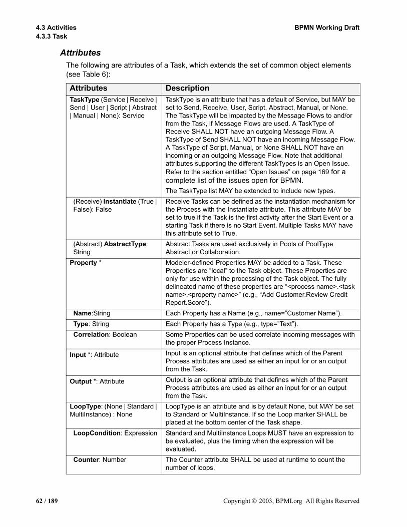
4.3 Activities BPMN Working Draft4.3.3 Task
AttributesThe following are attributes of a Task, which extends the set of common object elements (see Table 6):
Attributes DescriptionTaskType (Service | Receive | Send | User | Script | Abstract | Manual | None): Service
TaskType is an attribute that has a default of Service, but MAY be set to Send, Receive, User, Script, Abstract, Manual, or None. The TaskType will be impacted by the Message Flows to and/or from the Task, if Message Flows are used. A TaskType of Receive SHALL NOT have an outgoing Message Flow. A TaskType of Send SHALL NOT have an incoming Message Flow. A TaskType of Script, Manual, or None SHALL NOT have an incoming or an outgoing Message Flow. Note that additional attributes supporting the different TaskTypes is an Open Issue. Refer to the section entitled “Open Issues” on page 169 for a complete list of the issues open for BPMN.The TaskType list MAY be extended to include new types.
(Receive) Instantiate (True | False): False
Receive Tasks can be defined as the instantiation mechanism for the Process with the Instantiate attribute. This attribute MAY be set to true if the Task is the first activity after the Start Event or a starting Task if there is no Start Event. Multiple Tasks MAY have this attribute set to True.
(Abstract) AbstractType: String
Abstract Tasks are used exclusively in Pools of PoolType Abstract or Collaboration.
Property * Modeler-defined Properties MAY be added to a Task. These Properties are “local” to the Task object. These Properties are only for use within the processing of the Task object. The fully delineated name of these properties are “<process name>.<task name>.<property name>” (e.g., “Add Customer.Review Credit Report.Score”).
Name:String Each Property has a Name (e.g., name=”Customer Name”). Type: String Each Property has a Type (e.g., type=”Text”). Correlation: Boolean Some Properties can be used correlate incoming messages with
the proper Process Instance.
Input *: Attribute Input is an optional attribute that defines which of the Parent Process attributes are used as either an input for or an output from the Task.
Output *: Attribute Output is an optional attribute that defines which of the Parent Process attributes are used as either an input for or an output from the Task.
LoopType: (None | Standard | MultiInstance) : None
LoopType is an attribute and is by default None, but MAY be set to Standard or MultiInstance. If so the Loop marker SHALL be placed at the bottom center of the Task shape.
LoopCondition: Expression Standard and MultiInstance Loops MUST have an expression to be evaluated, plus the timing when the expression will be evaluated.
Counter: Number The Counter attribute SHALL be used at runtime to count the number of loops.
62 / 189 Copyright 2003, BPMI.org All Rights Reserved
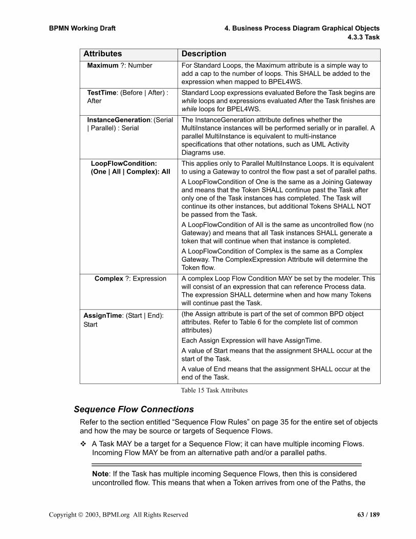
BPMN Working Draft 4. Business Process Diagram Graphical Objects4.3.3 Task
Table 15 Task Attributes
Sequence Flow ConnectionsRefer to the section entitled “Sequence Flow Rules” on page 35 for the entire set of objects and how the may be source or targets of Sequence Flows.
A Task MAY be a target for a Sequence Flow; it can have multiple incoming Flows. Incoming Flow MAY be from an alternative path and/or a parallel paths.
Note: If the Task has multiple incoming Sequence Flows, then this is considered uncontrolled flow. This means that when a Token arrives from one of the Paths, the
Maximum ?: Number For Standard Loops, the Maximum attribute is a simple way to add a cap to the number of loops. This SHALL be added to the expression when mapped to BPEL4WS.
TestTime: (Before | After) : After
Standard Loop expressions evaluated Before the Task begins are while loops and expressions evaluated After the Task finishes are while loops for BPEL4WS.
InstanceGeneration: (Serial | Parallel) : Serial
The InstanceGeneration attribute defines whether the MultiInstance instances will be performed serially or in parallel. A parallel MultiInstance is equivalent to multi-instance specifications that other notations, such as UML Activity Diagrams use.
LoopFlowCondition: (One | All | Complex): All
This applies only to Parallel MultiInstance Loops. It is equivalent to using a Gateway to control the flow past a set of parallel paths.A LoopFlowCondition of One is the same as a Joining Gateway and means that the Token SHALL continue past the Task after only one of the Task instances has completed. The Task will continue its other instances, but additional Tokens SHALL NOT be passed from the Task. A LoopFlowCondition of All is the same as uncontrolled flow (no Gateway) and means that all Task instances SHALL generate a token that will continue when that instance is completed. A LoopFlowCondition of Complex is the same as a Complex Gateway. The ComplexExpression Attribute will determine the Token flow.
Complex ?: Expression A complex Loop Flow Condition MAY be set by the modeler. This will consist of an expression that can reference Process data. The expression SHALL determine when and how many Tokens will continue past the Task.
AssignTime: (Start | End): Start
(the Assign attribute is part of the set of common BPD object attributes. Refer to Table 6 for the complete list of common attributes)Each Assign Expression will have AssignTime.A value of Start means that the assignment SHALL occur at the start of the Task. A value of End means that the assignment SHALL occur at the end of the Task.
Attributes Description
Copyright 2003, BPMI.org All Rights Reserved 63 / 189

4.4 Gateways BPMN Working Draft4.3.3 Task
Task will be instantiated. It will not wait for the arrival of Tokens from the other paths. If another Token arrives from the same path or another path, then a separate instance of the Task will be created. If the flow needs to be controlled, then the flow should converge with a Gateway that precedes the Task (Refer to the section entitled “Gateways” on page 64 for more information on Gateways).
If the Task does not have an incoming Sequence Flow, and there is no Start Event for the Process, then the Task MUST be instantiated when the process is instantiated.
An exception to this are Tasks that are defined as being Compensation activities (have the Compensation Marker). Compensation Tasks are not considered a part of the normal flow and SHALL NOT be instantiated when the Process is instantiated.
A Task MAY be a source for a Sequence Flow; it can have multiple outgoing Flows. If there are multiple outgoing Sequence Flows, then this means that a separate parallel path is being created for each Flow.
Tokens will be generated for each outgoing Sequence Flow from the Task. The TokenIDs for each of the Tokens will be set such that it can be identified that the Tokens are all from the same parallel Fork (AND-Split) and the number of Tokens in the group
If the Task does not have an outgoing Sequence Flow, and there is no End Event for the Process, then the Task marks the end of one or more paths in the Process. When the Task ends and there are no other parallel paths active, then the Process MUST be completed.
An exception to this are Tasks that are defined as being Compensation activities (have the Compensation Marker). Compensation Tasks are not considered a part of the normal flow and SHALL NOT mark the end of the Process.
Message Flow ConnectionsRefer to the section entitled “Message Flow Rules” on page 36 for the entire set of objects and how the may be source or targets of Sequence Flows.
Note: All Message Flows must connect two separate Pools. They can connect to the Pool boundary or to flow objects within the Pool boundary. They cannot connect two objects within the same Pool.
A Task MAY be the target for Message Flows; it can have zero or one incoming Message Flows.
A Task MAY be a source for a Message Flow; it can have zero or more outgoing Message Flows.
4.4 GatewaysGateways are modeling elements that are used to control how Sequence Flows interact as they converge and diverge within a Process. If the flow does not need to be controlled, then
64 / 189 Copyright 2003, BPMI.org All Rights Reserved

BPMN Working Draft 4. Business Process Diagram Graphical Objects4.3.3 Task
a Gateway is not needed. The term “Gateway” implies that there is a gating mechanism that either allows or disallows passage through the Gateway--that is, as Tokens arrive at a Gateway, they can be Merged together on input and/or split apart on output as the Gateway mechanisms are invoked. To be more descriptive, the control of the output flow a Gateway is actually a collection of “Gates” and the behavior a particular Gateway will determine how many of the Gates will be available for the continuation of flow. There will be one Gate for each outgoing Sequence Flow of the Gateway.
A Gateway is a diamond (see Figure 13), which has been used in many flow chart notations for exclusive branching and is familiar to most modelers.
A Gateway is a diamond that MUST be drawn with a single thin black line, and MUST have a white or clear fill.
The use of text, color, size, and lines for a Gateway MUST follow the rules defined in section 3.3 on page 34.
Figure 13 A Gateway
Note: Although the shape of a Gateway is a diamond, it is not a requirement that incoming and outgoing Sequence Flow must connect to the corners of the diamond. Sequence Flow can connect to any position on the boundary of the Gateway shape.
Gateways can define all the types of business process Sequence Flow behavior: Decisions/branching (OR-Split; exclusive--XOR, inclusive--OR, and complex), merging (OR-Join), forking (AND-Split), and joining (AND-Join). Thus, while the diamond has been used traditionally for exclusive decisions, BPMN extends the behavior of the diamonds to reflect any type of Sequence Flow control. Each type of Gateway will have an internal indicator or marker to show the type of Gateway that is being used (see Figure 14).
Copyright 2003, BPMI.org All Rights Reserved 65 / 189
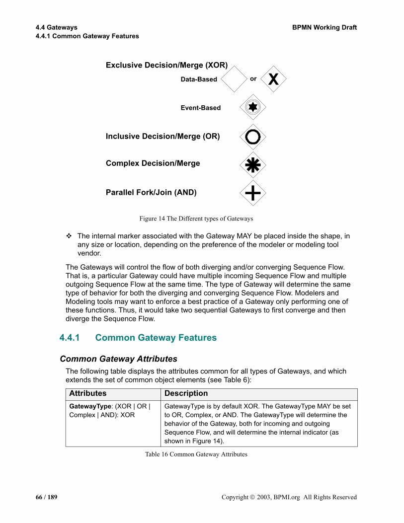
4.4 Gateways BPMN Working Draft4.4.1 Common Gateway Features
Figure 14 The Different types of Gateways
The internal marker associated with the Gateway MAY be placed inside the shape, in any size or location, depending on the preference of the modeler or modeling tool vendor.
The Gateways will control the flow of both diverging and/or converging Sequence Flow. That is, a particular Gateway could have multiple incoming Sequence Flow and multiple outgoing Sequence Flow at the same time. The type of Gateway will determine the same type of behavior for both the diverging and converging Sequence Flow. Modelers and Modeling tools may want to enforce a best practice of a Gateway only performing one of these functions. Thus, it would take two sequential Gateways to first converge and then diverge the Sequence Flow.
4.4.1 Common Gateway Features
Common Gateway AttributesThe following table displays the attributes common for all types of Gateways, and which extends the set of common object elements (see Table 6):
Table 16 Common Gateway Attributes
Attributes DescriptionGatewayType: (XOR | OR | Complex | AND): XOR
GatewayType is by default XOR. The GatewayType MAY be set to OR, Complex, or AND. The GatewayType will determine the behavior of the Gateway, both for incoming and outgoing Sequence Flow, and will determine the internal indicator (as shown in Figure 14).
Parallel Fork/Join (AND)
Exclusive Decision/Merge (XOR)
Complex Decision/Merge
Data-Based
Event-Based
Inclusive Decision/Merge (OR)
Xor
66 / 189 Copyright 2003, BPMI.org All Rights Reserved

BPMN Working Draft 4. Business Process Diagram Graphical Objects4.4.2 Exclusive Gateways (XOR)
Common Gateway Sequence Flow ConnectionsThis section applies to all Gateways. Additional Sequence Flow Connection rules will be specified for each type of Gateway in the sections below. Refer to the section entitled “Sequence Flow Rules” on page 35 for the entire set of objects and how the may be source or targets of Sequence Flows.
A Gateway MAY be a target for a Sequence Flow; it can have zero or more incoming Sequence Flows. An incoming Flow MAY be from an alternative path or a parallel path.
If the Gateway does not have an incoming Sequence Flow, and there is no Start Event for the Process, then the Gateway’s divergence behavior, depending on the GatewayType attribute (see below), SHALL be performed when the Process is instantiated.
A Gateway MAY be a source of Sequence Flow; it can have zero or more outgoing Flows.
A Gateway MAY have both multiple incoming and outgoing Sequence Flow.
Message Flow ConnectionsThis section applies to both Data-Based and Event-Based Exclusive Gateways. Refer to the section entitled “Message Flow Rules” on page 36 for the entire set of objects and how the may be source or targets of Sequence Flows.
An Gateway MAY NOT be a target for a Message Flow.
An Gateway MAY NOT be a source for a Message Flow.
4.4.2 Exclusive Gateways (XOR)Exclusive Gateways (Decisions) are locations within a business process where the Sequence Flow can take two or more alternative paths. This is basically the “fork in the road” for a process. For a given performance (or instance) of the process, only one of the paths can be taken (this should not be confused with forking of paths—refer to the section entitled “Forking Flow” on page 105). A Decision is not an activity from the business process perspective, but is a type of Gateway that control the Sequence Flow between activities. It can be thought of as a question that is asked at that point in the Process. The question has a defined set of alternative answers (Gates). Each Decision Gate is associated with a condition expression found within an outgoing Sequence Flow. When an Gate is chosen during the performance of the Process, the corresponding Sequence Flow is then chosen. A Token arriving at the Decision would be directed down the appropriate path, based on the chosen Gate.
The Exclusive Decision has two or more outgoing Sequence Flows, but only one of them may be taken during the performance of the Process. Thus, the Exclusive Decision defines a set of alternative paths for the Token to take as it traverses the Flows. There are two types of Exclusive Decisions: Data-Based and Event-Based.
Data-BasedThe Data-Based Exclusive Gateways are the most commonly used type of Gateways. The set of Gates for Data-Based Exclusive Decisions are based on the boolean expression
Copyright 2003, BPMI.org All Rights Reserved 67 / 189
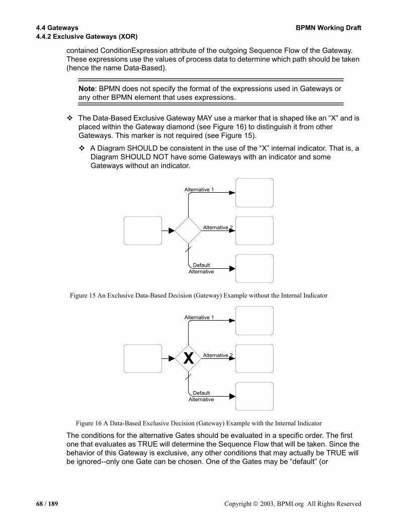
4.4 Gateways BPMN Working Draft4.4.2 Exclusive Gateways (XOR)
contained ConditionExpression attribute of the outgoing Sequence Flow of the Gateway. These expressions use the values of process data to determine which path should be taken (hence the name Data-Based).
Note: BPMN does not specify the format of the expressions used in Gateways or any other BPMN element that uses expressions.
The Data-Based Exclusive Gateway MAY use a marker that is shaped like an “X” and is placed within the Gateway diamond (see Figure 16) to distinguish it from other Gateways. This marker is not required (see Figure 15).
A Diagram SHOULD be consistent in the use of the “X” internal indicator. That is, a Diagram SHOULD NOT have some Gateways with an indicator and some Gateways without an indicator.
Figure 15 An Exclusive Data-Based Decision (Gateway) Example without the Internal Indicator
Figure 16 A Data-Based Exclusive Decision (Gateway) Example with the Internal Indicator
The conditions for the alternative Gates should be evaluated in a specific order. The first one that evaluates as TRUE will determine the Sequence Flow that will be taken. Since the behavior of this Gateway is exclusive, any other conditions that may actually be TRUE will be ignored--only one Gate can be chosen. One of the Gates may be “default” (or
DefaultAlternative
Alternative 2
Alternative 1
DefaultAlternative
X Alternative 2
Alternative 1
68 / 189 Copyright 2003, BPMI.org All Rights Reserved

BPMN Working Draft 4. Business Process Diagram Graphical Objects4.4.2 Exclusive Gateways (XOR)
otherwise), and is the last Gate considered. This means that if none of the other Gates are chosen, then the default Gate will be chosen—along with its associated Sequence Flow.
The default Gate is not mandatory for a Gateway. This means that if it is not used, then it is up to the modeler to insure that at least one Gate be valid at runtime. BPMN does not specify what will happen if there are no valid Gates. However, BPMN does specify that there SHALL NOT be implicit flow and that all normal flow of a Process must be expressed through Sequence Flow. This would mean that a Process Model that has a Gateway that potentially does not have a valid Gate at runtime is an invalid model.
Figure 17 An Exclusive Merge (Gateway) (without the Internal Indicator)
Exclusive Gateways can also be used as a merge (see Figure 17), although it is rarely required for the modeler to use them this way. The merging behavior of the Gateway can also be modeled as seen in Figure 18. The behavior of Figure 17 and Figure 18 are the same if all the incoming flow are alternative. This is true because when a Token arrives at an activity, that activity will be instantiated. The Exclusive Gateway merely merges the Sequence Flow into a single Sequence Flow, but it does not restrict the flow of Tokens through the Gateway. That is, if there happens to be some parallel incoming Sequence Flow for the Gateway, each Token that traverses the Sequence Flow into the Gateway will immediate pass through without waiting for any other potential Token that may come along. If another Token happens through the Gateway, it will also continue through without being restricted by any previous or future Tokens that may also pass through. Thus, it is not necessary to have the Sequence Flow merge through the Gateway prior to the activity.
Copyright 2003, BPMI.org All Rights Reserved 69 / 189
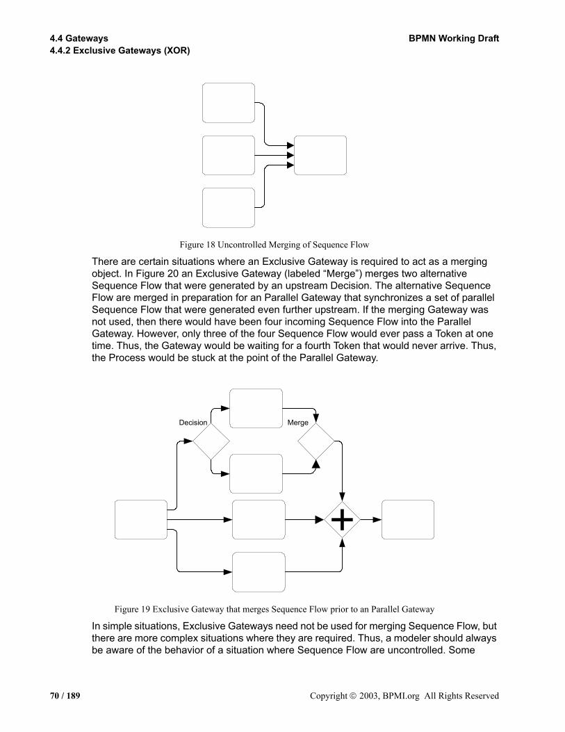
4.4 Gateways BPMN Working Draft4.4.2 Exclusive Gateways (XOR)
Figure 18 Uncontrolled Merging of Sequence Flow
There are certain situations where an Exclusive Gateway is required to act as a merging object. In Figure 20 an Exclusive Gateway (labeled “Merge”) merges two alternative Sequence Flow that were generated by an upstream Decision. The alternative Sequence Flow are merged in preparation for an Parallel Gateway that synchronizes a set of parallel Sequence Flow that were generated even further upstream. If the merging Gateway was not used, then there would have been four incoming Sequence Flow into the Parallel Gateway. However, only three of the four Sequence Flow would ever pass a Token at one time. Thus, the Gateway would be waiting for a fourth Token that would never arrive. Thus, the Process would be stuck at the point of the Parallel Gateway.
Figure 19 Exclusive Gateway that merges Sequence Flow prior to an Parallel Gateway
In simple situations, Exclusive Gateways need not be used for merging Sequence Flow, but there are more complex situations where they are required. Thus, a modeler should always be aware of the behavior of a situation where Sequence Flow are uncontrolled. Some
MergeDecision
70 / 189 Copyright 2003, BPMI.org All Rights Reserved
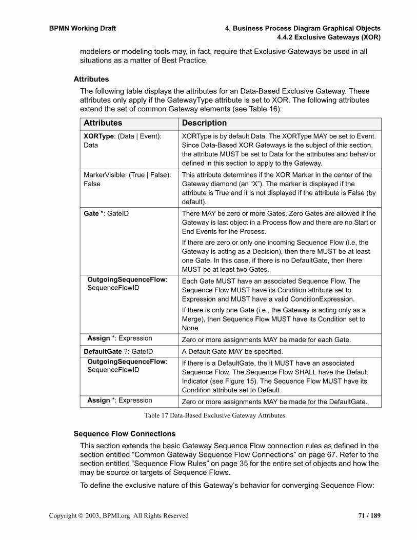
BPMN Working Draft 4. Business Process Diagram Graphical Objects4.4.2 Exclusive Gateways (XOR)
modelers or modeling tools may, in fact, require that Exclusive Gateways be used in all situations as a matter of Best Practice.
AttributesThe following table displays the attributes for an Data-Based Exclusive Gateway. These attributes only apply if the GatewayType attribute is set to XOR. The following attributes extend the set of common Gateway elements (see Table 16):
Table 17 Data-Based Exclusive Gateway Attributes
Sequence Flow ConnectionsThis section extends the basic Gateway Sequence Flow connection rules as defined in the section entitled “Common Gateway Sequence Flow Connections” on page 67. Refer to the section entitled “Sequence Flow Rules” on page 35 for the entire set of objects and how the may be source or targets of Sequence Flows.
To define the exclusive nature of this Gateway’s behavior for converging Sequence Flow:
Attributes DescriptionXORType: (Data | Event): Data
XORType is by default Data. The XORType MAY be set to Event. Since Data-Based XOR Gateways is the subject of this section, the attribute MUST be set to Data for the attributes and behavior defined in this section to apply to the Gateway.
MarkerVisible: (True | False): False
This attribute determines if the XOR Marker in the center of the Gateway diamond (an “X”). The marker is displayed if the attribute is True and it is not displayed if the attribute is False (by default).
Gate *: GateID There MAY be zero or more Gates. Zero Gates are allowed if the Gateway is last object in a Process flow and there are no Start or End Events for the Process.If there are zero or only one incoming Sequence Flow (i.e, the Gateway is acting as a Decision), then there MUST be at least one Gate. In this case, if there is no DefaultGate, then there MUST be at least two Gates.
OutgoingSequenceFlow: SequenceFlowID
Each Gate MUST have an associated Sequence Flow. The Sequence Flow MUST have its Condition attribute set to Expression and MUST have a valid ConditionExpression.If there is only one Gate (i.e., the Gateway is acting only as a Merge), then Sequence Flow MUST have its Condition set to None.
Assign *: Expression Zero or more assignments MAY be made for each Gate.
DefaultGate ?: GateID A Default Gate MAY be specified.OutgoingSequenceFlow: SequenceFlowID
If there is a DefaultGate, the it MUST have an associated Sequence Flow. The Sequence Flow SHALL have the Default Indicator (see Figure 15). The Sequence Flow MUST have its Condition attribute set to Default.
Assign *: Expression Zero or more assignments MAY be made for the DefaultGate.
Copyright 2003, BPMI.org All Rights Reserved 71 / 189
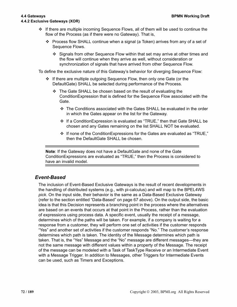
4.4 Gateways BPMN Working Draft4.4.2 Exclusive Gateways (XOR)
If there are multiple incoming Sequence Flows, all of them will be used to continue the flow of the Process (as if there were no Gateway). That is,
Process flow SHALL continue when a signal (a Token) arrives from any of a set of Sequence Flows.
Signals from other Sequence Flow within that set may arrive at other times and the flow will continue when they arrive as well, without consideration or synchronization of signals that have arrived from other Sequence Flow.
To define the exclusive nature of this Gateway’s behavior for diverging Sequence Flow:
If there are multiple outgoing Sequence Flow, then only one Gate (or the DefaultGate) SHALL be selected during performance of the Process.
The Gate SHALL be chosen based on the result of evaluating the ConditionExpression that is defined for the Sequence Flow associated with the Gate.
The Conditions associated with the Gates SHALL be evaluated in the order in which the Gates appear on the list for the Gateway.
If a ConditionExpression is evaluated as “TRUE,” then that Gate SHALL be chosen and any Gates remaining on the list SHALL NOT be evaluated.
If none of the ConditionExpressions for the Gates are evaluated as “TRUE,” then the DefaultGate SHALL be chosen.
Note: If the Gateway does not have a DefaultGate and none of the Gate ConditionExpressions are evaluated as “TRUE,” then the Process is considered to have an invalid model.
Event-BasedThe inclusion of Event-Based Exclusive Gateways is the result of recent developments in the handling of distributed systems (e.g., with pi-calculus) and will map to the BPEL4WS pick. On the input side, their behavior is the same as a Data-Based Exclusive Gateway (refer to the section entitled “Data-Based” on page 67 above). On the output side, the basic idea is that this Decision represents a branching point in the process where the alternatives are based on an events that occurs at that point in the Process, rather than the evaluation of expressions using process data. A specific event, usually the receipt of a message, determines which of the paths will be taken. For example, if a company is waiting for a response from a customer, they will perform one set of activities if the customer responds “Yes” and another set of activities if the customer responds “No.” The customer’s response determines which path is taken. The identity of the Message determines which path is taken. That is, the “Yes” Message and the “No” message are different messages—they are not the same message with different values within a property of the Message. The receipt of the message can be modeled with a Task of TaskType Receive or an Intermediate Event with a Message Trigger. In addition to Messages, other Triggers for Intermediate Events can be used, such as Timers and Exceptions.
72 / 189 Copyright 2003, BPMI.org All Rights Reserved
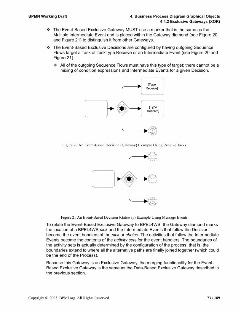
BPMN Working Draft 4. Business Process Diagram Graphical Objects4.4.2 Exclusive Gateways (XOR)
The Event-Based Exclusive Gateway MUST use a marker that is the same as the Multiple Intermediate Event and is placed within the Gateway diamond (see Figure 20 and Figure 21) to distinguish it from other Gateways.
The Event-Based Exclusive Decisions are configured by having outgoing Sequence Flows target a Task of TaskType Receive or an Intermediate Event (see Figure 20 and Figure 21).
All of the outgoing Sequence Flows must have this type of target; there cannot be a mixing of condition expressions and Intermediate Events for a given Decision.
Figure 20 An Event-Based Decision (Gateway) Example Using Receive Tasks
Figure 21 An Event-Based Decision (Gateway) Example Using Message Events
To relate the Event-Based Exclusive Gateway to BPEL4WS, the Gateway diamond marks the location of a BPEL4WS pick and the Intermediate Events that follow the Decision become the event handlers of the pick or choice. The activities that follow the Intermediate Events become the contents of the activity sets for the event handlers. The boundaries of the activity sets is actually determined by the configuration of the process; that is, the boundaries extend to where all the alternative paths are finally joined together (which could be the end of the Process).
Because this Gateway is an Exclusive Gateway, the merging functionality for the Event-Based Exclusive Gateway is the same as the Data-Based Exclusive Gateway described in the previous section.
[TypeReceive]
[TypeReceive]
Copyright 2003, BPMI.org All Rights Reserved 73 / 189

4.4 Gateways BPMN Working Draft4.4.2 Exclusive Gateways (XOR)
AttributesThe following table displays the attributes for an Event-Based Exclusive Gateway. These attributes only apply if the GatewayType attribute is set to XOR. The following attributes extend the set of common Gateway elements (see Table 16):
Table 18 Event-Based Exclusive Gateway Attributes
Sequence Flow ConnectionsThis section extends the basic Gateway Sequence Flow connection rules as defined in the section entitled “Common Gateway Sequence Flow Connections” on page 67. Refer to the section entitled “Sequence Flow Rules” on page 35 for the entire set of objects and how the may be source or targets of Sequence Flows.
To define the exclusive nature of this Gateway’s behavior for converging Sequence Flow:
If there are multiple incoming Sequence Flows, all of them will be used to continue the flow of the Process (as if there were no Gateway). That is,
Process flow SHALL continue when a signal (a Token) arrives from any of a set of Sequence Flows.
Signals from other Sequence Flow within that set may arrive at other times and the flow will continue when they arrive as well, without consideration or synchronization of signals that have arrived from other Sequence Flow.
To define the exclusive nature of this Gateway’s behavior for diverging Sequence Flow:
Only one Gate SHALL be selected during performance of the Process.
The Gate SHALL be chosen based on the Target of the Gate’s Sequence Flow.
Attributes DescriptionXORType: (Data | Event): Event
XORType is by default Data. The XORType MAY be set to Event. Since Event-Based XOR Gateways is the subject of this section, the attribute MUST be set to Event for the attributes and behavior defined in this section to apply to the Gateway.
Gate 2+: GateID There MUST be two or more Gates. (Note that this type of Gateway does not act only as a Merge--it is always a Decision, at least.)
OutgoingSequenceFlow: SequenceFlowID
Each Gate MUST have an associated Sequence Flow. The Sequence Flow MUST have its Condition attribute set to None (there is not an evaluation of a condition expression).
Target: ObjectID The targets of the Sequence flow MUST be an Intermediate Event or a Task of TaskType Receive.Intermediate Events with Trigger Compensation, Multiple, or Branching SHALL NOT be allowed as a Target.If a Receive Task is the Target for one Alterative, then a Message Intermediate Event SHALL NOT be allowed for Targets of other Gates.
Assign *: Expression Zero or more assignments MAY be made for each Gate.
74 / 189 Copyright 2003, BPMI.org All Rights Reserved
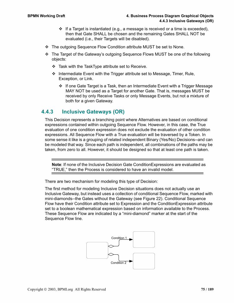
BPMN Working Draft 4. Business Process Diagram Graphical Objects4.4.3 Inclusive Gateways (OR)
If a Target is instantiated (e.g., a message is received or a time is exceeded), then that Gate SHALL be chosen and the remaining Gates SHALL NOT be evaluated (i.e., their Targets will be disabled).
The outgoing Sequence Flow Condition attribute MUST be set to None.
The Target of the Gateway’s outgoing Sequence Flows MUST be one of the following objects:
Task with the TaskType attribute set to Receive.
Intermediate Event with the Trigger attribute set to Message, Timer, Rule, Exception, or Link.
If one Gate Target is a Task, then an Intermediate Event with a Trigger Message MAY NOT be used as a Target for another Gate. That is, messages MUST be received by only Receive Tasks or only Message Events, but not a mixture of both for a given Gateway.
4.4.3 Inclusive Gateways (OR)This Decision represents a branching point where Alternatives are based on conditional expressions contained within outgoing Sequence Flow. However, in this case, the True evaluation of one condition expression does not exclude the evaluation of other condition expressions. All Sequence Flow with a True evaluation will be traversed by a Token. In some sense it like is a grouping of related independent Binary (Yes/No) Decisions--and can be modeled that way. Since each path is independent, all combinations of the paths may be taken, from zero to all. However, it should be designed so that at least one path is taken.
Note: If none of the Inclusive Decision Gate ConditionExpressions are evaluated as “TRUE,” then the Process is considered to have an invalid model.
There are two mechanism for modeling this type of Decision:
The first method for modeling Inclusive Decision situations does not actually use an Inclusive Gateway, but instead uses a collection of conditional Sequence Flow, marked with mini-diamonds--the Gates without the Gateway (see Figure 22). Conditional Sequence Flow have their Condition attribute set to Expression and the ConditionExpression attribute set to a boolean mathematical expression based on information available to the Process. These Sequence Flow are indicated by a “mini-diamond” marker at the start of the Sequence Flow line.
Condition 1
Condition 2
Copyright 2003, BPMI.org All Rights Reserved 75 / 189

4.4 Gateways BPMN Working Draft4.4.3 Inclusive Gateways (OR)
Figure 22 An Inclusive Decision using Conditional Sequence Flow
There are some restrictions in using the conditional Sequence Flow (with mini-diamonds):
• The source object MUST NOT be an Event. The source object MAY a Gateway, but the mini-diamond SHALL NOT be displayed in this case. The source object MAY be an activity (Task or Sub-Process) and the mini-diamond SHALL be displayed in this case.
• A source Gateway MUST NOT be of type AND (Parallel).
• If a conditional Sequence Flow is used from a source activity, then there MUST be at least one other outgoing Sequence Flow from that activity
• The additional Sequence Flow(s) MAY also be conditional, but it is not required that are conditional.
The second method for modeling Inclusive Decision situations uses an OR Gateway (see Figure 23), sometimes in combination with other Gateways. A marker will be placed in the center of the Gateway to indicate that the behavior of the Gateway is inclusive.
The Inclusive Gateway MUST use a marker that is in the shape of a circle or an “O” and is placed within the Gateway diamond (see Figure 23) to distinguish it from other Gateways.
Figure 23 An Inclusive Decision using an OR Gateway
The behavior of the model depicted in Figure 22 is equivalent to the behavior of the model depicted in Figure 23. Again, it is up to the modeler to insure that at least one of the conditions will be TRUE when the Process is performed.
When the Inclusive Gateway is used as a Merge, it will wait for (synchronize) all Tokens that have been produced upstream. It does not require that all incoming Sequence Flow produce a Token (as the Parallel Gateway does). It requires that all Sequence Flow that were actually produced by an upstream (by an Inclusive OR situation, for example). If an upstream Inclusive OR produces two out of a possible three Tokens, then a downstream Inclusive OR will synchronize those two Tokens and not wait for another Token, even though there are three incoming Sequence Flow (see Figure 24).
Condition 2
Condition 1
76 / 189 Copyright 2003, BPMI.org All Rights Reserved
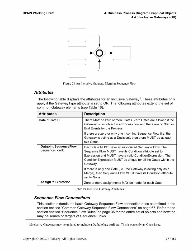
BPMN Working Draft 4. Business Process Diagram Graphical Objects4.4.3 Inclusive Gateways (OR)
Figure 24 An Inclusive Gateway Merging Sequence Flow
AttributesThe following table displays the attributes for an Inclusive Gateway1. These attributes only apply if the GatewayType attribute is set to OR. The following attributes extend the set of common Gateway elements (see Table 16):
Table 19 Inclusive Gateway Attributes
Sequence Flow ConnectionsThis section extends the basic Gateway Sequence Flow connection rules as defined in the section entitled “Common Gateway Sequence Flow Connections” on page 67. Refer to the section entitled “Sequence Flow Rules” on page 35 for the entire set of objects and how the may be source or targets of Sequence Flows.
1.Inclusive Gateways may be updated to include a DefaultGate attribute. This is currently an Open Issue.
Attributes DescriptionGate *: GateID There MAY be zero or more Gates. Zero Gates are allowed if the
Gateway is last object in a Process flow and there are no Start or End Events for the Process.If there are zero or only one incoming Sequence Flow (i.e, the Gateway is acting as a Decision), then there MUST be at least two Gates.
OutgoingSequenceFlow: SequenceFlowID
Each Gate MUST have an associated Sequence Flow. The Sequence Flow MUST have its Condition attribute set to Expression and MUST have a valid ConditionExpression. The ConditionExpression MUST be unique for all the Gates within the Gateway.If there is only one Gate (i.e., the Gateway is acting only as a Merge), then Sequence Flow MUST have its Condition attribute set to None.
Assign *: Expression Zero or more assignments MAY be made for each Gate.
Copyright 2003, BPMI.org All Rights Reserved 77 / 189

4.4 Gateways BPMN Working Draft4.4.4 Complex Gateways
To define the inclusive nature of this Gateway’s behavior for converging Sequence Flow:
If there are multiple incoming Sequence Flows, one or more of them will be used to continue the flow of the Process. That is,
Process flow SHALL continue when the signals (Tokens) arrive from all of the incoming Sequence Flow that are expecting a signal based on the upstream structure of the Process (e.g., an upstream Inclusive Decision).
Some of the incoming Sequence Flow will not have signals and the pattern of which Sequence Flow will have signals may change for different instantiations of the Process.
Note: Incoming Sequence Flow that have a source that is a downstream activity (that is, is part of a loop) will be treated differently than those that have an upstream source. They will be considered as part of a different set of Sequence Flow from those Sequence Flow that have a source that is an upstream activity.
To define the inclusive nature of this Gateway’s behavior for diverging Sequence Flow:
One or more Gates SHALL be selected during performance of the Process.
The Gates SHALL be chosen based on the Condition expression that is defined for the Sequence Flow associated with the Gates.
The Condition associated with all Gates SHALL be evaluated.
If a Condition is evaluated as “TRUE,” then that Gate SHALL be chosen, independent of what other Gates have or have not been chosen.
4.4.4 Complex GatewaysBPMN includes a Complex Gateway to handle situations that are not easily handled through the other types of Gateways. Complex Gateways can also be used to combine a set of linked simple Gateways into a single, more compact situation. Modelers can provide complex expressions that determine the merging and/or splitting behavior of the Gateway.
The Complex Gateway MUST use a marker that is in the shape of an asterisk and is placed within the Gateway diamond (see Figure 25) to distinguish it from other Gateways.
When the Gateway is used as a Decision (see Figure 25), then there will be an expression that will determine which of the outgoing Sequence Flow will be chosen for the Process to continue. The expression may refer to process data and the status of the incoming Sequence Flow. For example, an expression may evaluate Process data and then select different sets of outgoing Sequence Flow, based on the results of the evaluation. However, The expression should be designed so that at least one of the outgoing Sequence Flow will be chosen.
78 / 189 Copyright 2003, BPMI.org All Rights Reserved

BPMN Working Draft 4. Business Process Diagram Graphical Objects4.4.4 Complex Gateways
Figure 25 A Complex Decision (Gateway)
When the Gateway is used as a Merge (see Figure 26), then there will be an expression that will determine which of the incoming Sequence Flow will be required for the Process to continue. The expression may refer to process data and the status of the incoming Sequence Flow. For example, an expression may specify that any 3 out of 5 incoming Tokens will continue the Process. Another example would be an expression that specifies that a Token is required from Sequence Flow “a” and that a Token from either Sequence Flow “b” or “c” is acceptable. However, the expression should be designed so that the Process is not stalled at that location.
Figure 26 A Complex Merge (Gateway)
Alternative 2
Alternative 1
Alternative 3
Alternative 4
Copyright 2003, BPMI.org All Rights Reserved 79 / 189

4.4 Gateways BPMN Working Draft4.4.4 Complex Gateways
AttributesThe following table displays the attributes for a Complex Gateway. These attributes only apply if the GatewayType attribute is set to Complex. The following attributes extend the set of common Gateway elements (see Table 16):
Table 20 Complex Gateway Attributes
Sequence Flow ConnectionsThis section extends the basic Gateway Sequence Flow connection rules as defined in the section entitled “Common Gateway Sequence Flow Connections” on page 67. Refer to the section entitled “Sequence Flow Rules” on page 35 for the entire set of objects and how the may be source or targets of Sequence Flows.
To define the complex nature of this Gateway’s behavior for converging Sequence Flow:
If there are multiple incoming Sequence Flows, one or more of them will be used to continue the flow of the Process. The exact combination of incoming Sequence Flows will be determined by the Gateway’s IncomingCondition expression.
Process flow SHALL continue when the appropriate number of signals (Tokens) arrives from appropriate incoming Sequence Flows.
Signals from other Sequence Flow within that set MAY arrive, but they SHALL NOT be used to continue the flow of the Process.
Attributes DescriptionGate *: GateID There MAY be zero or more Gates. Zero Gates are allowed if the
Gateway is last object in a Process flow and there are no Start or End Events for the Process.If there are zero or only one incoming Sequence Flow, then there MUST be at least two Gates.
OutgoingSequenceFlow: SequenceFlowID
Each Gate MUST have an associated Sequence Flow. Each Gate MUST have an associated Sequence Flow. The Sequence Flow MUST have its Condition attribute set to None. If there is only one Gate (i.e., the Gateway is acting only as a Merge), then Sequence Flow MUST have its Condition attribute set to None.
Assign *: Expression Zero or more assignments MAY be made for each Gate.
IncomingCondition ?: Expression
If there are Multiple incoming Sequence Flow, an IncomingCondition expression MUST be set by the modeler. This will consist of an expression that can reference Sequence Flow names and or Process Properties (Data). More TBD
OutgoingCondition ?: Expression
If there are Multiple outgoing Sequence Flow, an OutgoingCondition expression MUST be set by the modeler. This will consist of an expression that can reference (outgoing) Sequence Flow IDs and or Process Properties (Data).
80 / 189 Copyright 2003, BPMI.org All Rights Reserved

BPMN Working Draft 4. Business Process Diagram Graphical Objects4.4.5 Parallel Gateways (AND)
Note: Incoming Sequence Flow that have a source that is a downstream activity (that is, is part of a loop) will be treated differently than those that have an upstream source. They will be considered as part of a different set of Sequence Flow from those Sequence Flow that have a source that is an upstream activity.
To define the inclusive nature of this Gateway’s behavior for diverging Sequence Flow:
One or more Gates SHALL be selected during performance of the Process.
The Gates SHALL be chosen based on the Gateway’s OutgoingCondition expression.
4.4.5 Parallel Gateways (AND)Parallel Gateways provide a mechanism to synchronize parallel flow and to create parallel flow. These Gateways are not required to create parallel flow, but they can be used to clarify the behavior of complex situations where a string of Gateways are used and parallel flow is required. In addition, some modelers may wish to create a “best practice” where Parallel Gateways are always used for creating parallel paths. This practice will create an extra modeling element where one is not required, but will provide a balanced approach where forking and joining elements can be paired up.
The Parallel Gateway MUST use a marker that is in the shape of an plus sign and is placed within the Gateway diamond (see Figure 27) to distinguish it from other Gateways.
Figure 27 A Parallel Gateway
Parallel Gateways are required for synchronizing parallel flow. Synchronization
B
C
A
Parallel SplitForking
Gateway
Copyright 2003, BPMI.org All Rights Reserved 81 / 189

4.4 Gateways BPMN Working Draft4.4.5 Parallel Gateways (AND)
Figure 28 Joining – the joining of parallel paths
AttributesThe following table displays the attributes for a Parallel Gateway. These attributes only apply if the GatewayType attribute is set to AND (Parallel). The following attributes extend the set of common Gateway elements (see Table 16):
Table 21 Parallel Gateway Attributes
Sequence Flow ConnectionsThis section extends the basic Gateway Sequence Flow connection rules as defined in the section entitled “Common Gateway Sequence Flow Connections” on page 67. Refer to the section entitled “Sequence Flow Rules” on page 35 for the entire set of objects and how the may be source or targets of Sequence Flows.
To define the parallel nature of this Gateway’s behavior for converging Sequence Flow:
If there are multiple incoming Sequence Flows, all of them will be used to continue the flow of the Process--the flow will be synchronized. That is,
Process flow SHALL continue when a signal (a Token) has arrived from all of a set of Sequence Flows (i.e., the process will wait for all signals to arrive before it can continue).
Attributes DescriptionGate *: GateID There MAY be zero or more Gates. Zero Gates are allowed if the
Gateway is last object in a Process flow and there are no Start or End Events for the Process.If there are zero or only one incoming Sequence Flow (i.e, the Gateway is acting as a fork), then there MUST be at least two Gates.
OutgoingSequenceFlow: SequenceFlowID
Each Gate MUST have an associated Sequence Flow. The Sequence Flow MUST have its Condition attribute set to None.
Assign *: Expression Zero or more assignments MAY be made for each Gate.
C
D
F
82 / 189 Copyright 2003, BPMI.org All Rights Reserved

BPMN Working Draft 4. Business Process Diagram Graphical Objects4.5.1 Pool
Note: Incoming Sequence Flow that have a source that is a downstream activity (that is, is part of a loop) will be treated differently than those that have an upstream source. They will be considered as part of a different set of Sequence Flow from those Sequence Flow that have a source that is an upstream activity.
To define the parallel nature of this Gateway’s behavior for diverging Sequence Flow:
All Gates SHALL be selected during performance of the Process.
4.5 Pools and LanesBPMN has a larger scope than BPEL4WS, and this scope is expressed in different dimensions. The dimension discussed in this section has to with defining business processes in a collaborative B2B environment. BPMN uses the concept known as “swimlanes” to help partition and/organize activities.
BPEL4WS is focused on a specific private process that is internal to a given Participant (i.e., a company or organization). BPEL4WS also can define an abstract process, but from the point of view of a single participant. It is possible that a BPMN Diagram may depict more than one private process, as well as the processes that show the collaboration between private processes or Participants. If so, then each private business process will be considered as being performed by different Participants. Graphically, each Participant will be partitioned; that is, will be contained within a rectangular box call a “Pool.” Pools can have sub-swimlanes that are called, simply, “Lanes.”
The section entitled “Uses of BPMN” on page 20 describes the uses of BPMN for modeling private processes and the interactions of processes in B2B scenarios. Pools and Lanes are designed to support these uses of BPMN.
4.5.1 PoolA Pool (also referred to as a “swimlane”) is a graphical container for partitioning a set of activities from other Pools, when modeling business-to-business situations.
A Pool is a square-cornered rectangle that MUST be drawn with a solid single black line (as seen in Figure 29), and MUST have a white or clear fill.
The use of text, color, size, and lines for a Pool MUST follow the rules defined in section 3.3 on page 34.
Figure 29 A Pool
To help with the clarity of the Diagram, A Pool will extend the entire length of the Diagram, either horizontally or vertically. However, there is no specific restriction to the size and/or
Nam
e
Copyright 2003, BPMI.org All Rights Reserved 83 / 189

4.5 Pools and Lanes BPMN Working Draft4.5.1 Pool
positioning of a Pool. Modelers and modeling tools can use Pools (and Lanes) in a flexible manner in the interest of conserving the “real estate” of a Diagram on a screen or a printed page.
A Pool acts as the container for the Sequence Flow between activities. The Sequence Flow can cross the boundaries between Lanes of a Pool, but cannot cross the boundaries of a Pool. The interaction between Pools, e.g., in a B2B context, is shown through Message Flows.
Another aspect of Pools is whether or not there is any activity detailed within the Pool. Thus, a given Pool may be shown as a “White Box,” with all details exposed, or as a “Black Box,” with all details hidden. No Sequence Flow is associated with a “Black Box” Pool, but Message Flows can attach to its boundaries (see Figure 30).
Figure 30 Message Flow connecting to the boundaries of two Pools
For a “White Box” Pool, the activities within are organized by Sequence Flows. Message Flows can cross the Pool boundary to attach to the appropriate activity (see Figure 31).
Man
ufac
ture
rFi
nanc
ial
Inst
itutio
n
Credit ResponseCredit Request
84 / 189 Copyright 2003, BPMI.org All Rights Reserved

BPMN Working Draft 4. Business Process Diagram Graphical Objects4.5.1 Pool
Figure 31 Message Flow connecting to flow objects within two Pools
All BPDs contain at least one Pool. In most cases, a BPD that consists of a single Pool will only display the activities of the Process and not display the boundaries of the Pool. Furthermore, many BPDs may show the “main” Pool without boundaries. That is, the activities that represent the work performed from the point of view of the modeler or the modeler’s organization are considered “internal” activities and may not be surrounded by the boundaries of a Pool, while the other Pools in the Diagram will have their boundary. (see Figure 32)
Figure 32 Main (Internal) Pool without boundaries
+
Credit CardAuthorization
Fina
ncia
lIn
stitu
tion
AuthorizePayment
Pack Goods Ship Goods
Process Order
+
Dis
tribu
tion
Sale
s
Supp
lier
AuthorizePayment Pack Goods Ship GoodsProcess Order
+
Financial Institution
Copyright 2003, BPMI.org All Rights Reserved 85 / 189
4.5 Pools and Lanes BPMN Working Draft4.5.2 Lane
AttributesThe following table displays the identified attributes of a Pool (Note that this is the complete set and it does not extend the set of common object attributes):
Table 22 Pool Attributes
4.5.2 LaneA Lane is a sub-partition within a Pool and will extend the entire length of the Pool, either vertically or horizontally (see Figure 33). Text associated with the Lane (e.g., its name and/or any attribute) can be placed inside the shape, in any direction or location, depending on the preference of the modeler or modeling tool vendor. Our examples place the name as a banner on the left side (for horizontal Pools) or at the top (for vertical Pools) on the other side of the line that separates the Pool name, however, this is not a requirement.
Attribute DescriptionID: String This is a unique ID that identifies the Pool from other objects
within the Diagram.
Name: String Name is an attribute that is text description of the Pool. If the Pool is the only one in the Diagram, it will share the name of the Diagram.
PoolType (Private | Abstract | Collaboration): Private
PoolType is an attribute that provides information about which lower-level language the Pool will be mapped. The default PoolType is Private which MAY be mapped to BPEL4WS. An Abstract Pool is also called the public interface of a process (or other web services) and MAY be mapped to languages such as WSCI. A Collaboration Pool will have two Lanes that represent business roles (e.g., buyer or seller) and will show the interactions between these roles. These pools MAY be mapped to languages such as ebXML.
Owner ?: String Owner is an optional attribute that will help identify the point-of-view of the Diagram. If the PoolType is Collaboration, then there is no specific Owner.
Lane +: LaneName There can be one or more Lanes within a Pool. If there is only one Lane, then that Lane shares the name of the Pool and only the Pool name is displayed. If there is more than one Lane, then each Lane has to have its own name and all names are displayed.
BoundaryVisible: (True | False): True
This attribute defines if the rectangular boundary for the Pool is visible. Only one Pool in the Diagram MAY have the attribute set to False.
86 / 189 Copyright 2003, BPMI.org All Rights Reserved
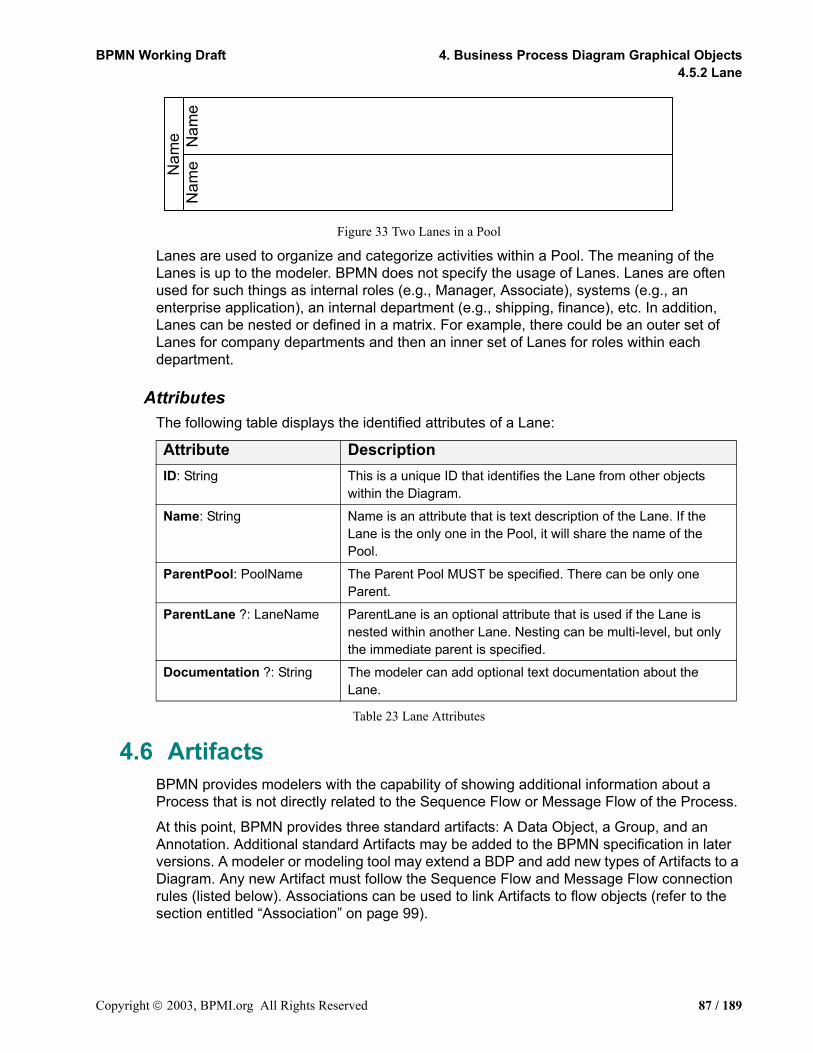
BPMN Working Draft 4. Business Process Diagram Graphical Objects4.5.2 Lane
Figure 33 Two Lanes in a Pool
Lanes are used to organize and categorize activities within a Pool. The meaning of the Lanes is up to the modeler. BPMN does not specify the usage of Lanes. Lanes are often used for such things as internal roles (e.g., Manager, Associate), systems (e.g., an enterprise application), an internal department (e.g., shipping, finance), etc. In addition, Lanes can be nested or defined in a matrix. For example, there could be an outer set of Lanes for company departments and then an inner set of Lanes for roles within each department.
AttributesThe following table displays the identified attributes of a Lane:
Table 23 Lane Attributes
4.6 ArtifactsBPMN provides modelers with the capability of showing additional information about a Process that is not directly related to the Sequence Flow or Message Flow of the Process.
At this point, BPMN provides three standard artifacts: A Data Object, a Group, and an Annotation. Additional standard Artifacts may be added to the BPMN specification in later versions. A modeler or modeling tool may extend a BDP and add new types of Artifacts to a Diagram. Any new Artifact must follow the Sequence Flow and Message Flow connection rules (listed below). Associations can be used to link Artifacts to flow objects (refer to the section entitled “Association” on page 99).
Attribute DescriptionID: String This is a unique ID that identifies the Lane from other objects
within the Diagram.
Name: String Name is an attribute that is text description of the Lane. If the Lane is the only one in the Pool, it will share the name of the Pool.
ParentPool: PoolName The Parent Pool MUST be specified. There can be only one Parent.
ParentLane ?: LaneName ParentLane is an optional attribute that is used if the Lane is nested within another Lane. Nesting can be multi-level, but only the immediate parent is specified.
Documentation ?: String The modeler can add optional text documentation about the Lane.
Nam
e Nam
eN
ame
Copyright 2003, BPMI.org All Rights Reserved 87 / 189

4.6 Artifacts BPMN Working Draft4.6.1 Common Artifact Attributes
4.6.1 Common Artifact AttributesThe following table displays the identified attributes of a Data Object (Note that this is the complete set and it does not extend the set of common object attributes):
Table 24 Common Artifact Attributes
4.6.2 Artifact Sequence Flow ConnectionsRefer to the section entitled “Sequence Flow Rules” on page 35 for the entire set of objects and how the may be source or targets of Sequence Flows.
An Artifact cannot be a target for a Sequence Flow.
An Artifact cannot be a source for a Sequence Flow.
4.6.3 Artifact Message Flow ConnectionsRefer to the section entitled “Message Flow Rules” on page 36 for the entire set of objects and how the may be source or targets of Sequence Flows.
A Artifact cannot be a target for a Message Flow.
A Artifact cannot be a source for a Message Flow.
4.6.4 Data ObjectIn BPMN, a Data Object is considered an artifacts and not a flow object. They are considered an artifact because they do not have any direct affect on the Sequence Flow or Message Flow of the Process, but they do provide information about what the Process does. That is, how documents, data, and other objects are used and updated during the Process. While the name “Data Object” may imply an electronic document, they can be used to represent many different types of objects, both electronic and physical.
In general, BPMN will not standardize many modeling artifacts. These will mainly be up to modelers and modeling tool vendors to create for their own purposes. However, equivalents of the BPMN Data Object are used by Document Management oriented workflow systems and many other process modeling methodologies. Thus, this object is used enough that it is important to standardize its shape and behavior.
Attribute DescriptionArtifactType: (DataObject | Group | Annotation)
The ArtifactType MAY be set to DataObject, Group, or Annotation. The ArtifactType list MAY be extended to include new types.
Id: String This is a unique ID that identifies the object from other objects within the Diagram.
Name: String Name is an attribute that is text description of the object.
Documentation ?: String The modeler MAY add optional text documentation about the object.
88 / 189 Copyright 2003, BPMI.org All Rights Reserved
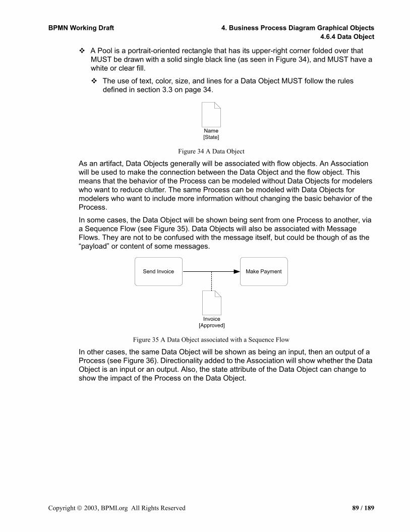
BPMN Working Draft 4. Business Process Diagram Graphical Objects4.6.4 Data Object
A Pool is a portrait-oriented rectangle that has its upper-right corner folded over that MUST be drawn with a solid single black line (as seen in Figure 34), and MUST have a white or clear fill.
The use of text, color, size, and lines for a Data Object MUST follow the rules defined in section 3.3 on page 34.
Figure 34 A Data Object
As an artifact, Data Objects generally will be associated with flow objects. An Association will be used to make the connection between the Data Object and the flow object. This means that the behavior of the Process can be modeled without Data Objects for modelers who want to reduce clutter. The same Process can be modeled with Data Objects for modelers who want to include more information without changing the basic behavior of the Process.
In some cases, the Data Object will be shown being sent from one Process to another, via a Sequence Flow (see Figure 35). Data Objects will also be associated with Message Flows. They are not to be confused with the message itself, but could be though of as the “payload” or content of some messages.
Figure 35 A Data Object associated with a Sequence Flow
In other cases, the same Data Object will be shown as being an input, then an output of a Process (see Figure 36). Directionality added to the Association will show whether the Data Object is an input or an output. Also, the state attribute of the Data Object can change to show the impact of the Process on the Data Object.
Name[State]
Invoice[Approved]
Send Invoice Make Payment
Copyright 2003, BPMI.org All Rights Reserved 89 / 189

4.6 Artifacts BPMN Working Draft4.6.5 Text Annotation
Figure 36 Data Objects shown as inputs and outputs
AttributesThe following table displays the attributes for Data Objects, and which extends the set of common Artifact elements (see Table 24). These attributes only apply if the ArtifactType attribute is set to DataObject:
Table 25 Data Object Attributes
4.6.5 Text AnnotationText Annotations are a mechanism for a modeler to provide additional information for the reader of a BPMN Diagram.
A Pool is an open rectangle that MUST be drawn with a solid single black line (as seen in Figure 37), and MUST have a white or clear fill.
The use of text, color, size, and lines for a Text Annotation MUST follow the rules defined in section 3.3 on page 34.
The Text Annotation object can be connected to a specific object on the Diagram with an Association (see Figure 37). Text associated with the Annotation can be placed within the bounds of the open rectangle.
Attribute DescriptionState ? State is an optional attribute that indicates the impact the Process
has had on the Data Object. Multiple Data Objects with the same name MAY share the same state within one Process.
Property * Modeler-defined Properties MAY be added to a Data Object. The fully delineated name of these properties are “<process name>.<task name>.<property name>” (e.g., “Add Customer.Review Credit Report.Score”).
Name:String Each Property has a Name (e.g., name=”Customer Name”). Type: String Each Property has a Type (e.g., type=”Text”).
Pool ?: PoolName If Pools are used, then the PoolName MUST be added to the object to identify its location.
Lane *: LaneName If the Pool has more than one Lane, then a LaneName MUST be added. There MAY be multiple Lanes listed if the Lanes are organized in matrix or overlap in a non-nested manner.
Approve PurchaseOrder
Purchase Order[Complete]
Purchase Order[Approved]
90 / 189 Copyright 2003, BPMI.org All Rights Reserved

BPMN Working Draft 4. Business Process Diagram Graphical Objects4.6.6 Group
Figure 37 A Text Annotation
Text Annotations do not affect the flow of the Process and do not map to any BPEL4WS elements.
AttributesThe following table displays the attributes for Annotations, and which extends the set of common Artifact elements (see Table 24). These attributes only apply if the ArtifactType attribute is set to Annotation:
Table 26 Text Annotation Attributes
4.6.6 GroupThe Group object is an artifact that provides a visual mechanism to group elements of a Process informally.
A Pool is a rounded corner rectangle that MUST be drawn with a solid dashed black line (as seen in Figure 38), and MUST have a white or clear fill.
The use of text, color, size, and lines for a Group MUST follow the rules defined in section 3.3 on page 34.
Figure 38 A Group Artifact
As an Artifact, a Group is not an activity or any flow object, and, therefore, cannot connect to Sequence Flow or Message Flow. In addition, Groups are not constrained by restrictions of Pools and Lanes. This means that a Group can stretch across the boundaries of a Pool to surround Diagram elements (see Figure 39), often to identify activities that exist within a distribute business-to-business transaction.
Attribute DescriptionText: String Text is an attribute that is text that the modeler wishes to
communicate to the reader of the Diagram.
Text Annotation Allowsa Modeler to provideadditional Information
Copyright 2003, BPMI.org All Rights Reserved 91 / 189

4.6 Artifacts BPMN Working Draft4.6.6 Group
Figure 39 A Group around activities in different Pools
Groups are often used to highlight certain sections of a Diagram without adding additional constraints for performance--as a Sub-Process would. The highlighted (grouped) section of the Diagram can be separated for reporting and analysis purposes. Groups do not affect the flow of the Process and do not map to any BPEL4WS elements.
92 / 189 Copyright 2003, BPMI.org All Rights Reserved

BPMN Working Draft
5. Connecting ObjectsThis section defines the graphical objects used to connect two objects together (i.e., the connecting lines of the Diagram) and how the flow progresses through a Process (i.e., through a straight sequence or through the creation of parallel or alternative paths).
5.1 Graphical Connecting ObjectsThere are two ways of connecting objects in BPMN: a Flow, either sequence or message, and an Association. Sequence Flows and Message Flows, to a certain extent, represent orthogonal aspects of the business processes depicted in a model, although they both affect the performance of activities within a Process. In keeping with this, Sequence Flows will generally flow in a single direction (either left to right, or top to bottom) and Message Flows will flow at a 90° from the Sequence Flows. This will help clarify the relationships for a Diagram that contains both Sequence Flows and Message Flows. However, BPMN does not restrict this relationship between the two types of Flows. A modeler can connect either type of Flow in any direction at any place in the Diagram.
The next three sections will describe how these types of connections function in BPMN.
5.1.1 Sequence FlowA Sequence Flow is used to show the order that activities will be performed in a Process. Each Flow has only one source and only one target. The source and target must be from the set of the following flow objects: Events (Start, Intermediate, and End), Activities (Task and Sub-Process), and Gateways. During performance (or simulation) of the process, a Token will leave the source flow object, traverse down the Sequence Flow, and enter the target flow object.
A Sequence Flow is line with a solid arrowhead that MUST be drawn with a solid single black line (as seen in Figure 40).
The use of text, color, size, and lines for a Sequence Flow MUST follow the rules defined in section 3.3 on page 34.
Figure 40 A Sequence Flow
BPMN does not use the term “Control Flow” when referring the lines represented by Sequence Flow or Message Flow. The start of an activity is “controlled” not only by Sequence Flow (the order of activities), but also by Message Flow (a message arriving), as well as other process factors, such as scheduled resources. Artifacts can be Associated with activities to show some of these other factors. Thus, we are using a more specific term, “Sequence Flow,” since these lines mainly illustrate the sequence that activities will be performed.
A Sequence Flow MAY have a conditional expression attribute, depending on its source object.
Copyright 2002, BPMI.org All Rights Reserved 93 / 189

5.1 Graphical Connecting Objects BPMN Working Draft5.1.1 Sequence Flow
This means that the condition expression must be evaluated before a Token can be generated and then leave the source object to traverse the Flow. The conditions are usually associated with Decision Gateways, but can also be used with activities.
If the source of the Sequence Flow is an activity, rather than Gateway, then a Conditional Marker, shaped as a “mini-diamond”,” MUST be used at the beginning of the Sequence Flow (see Figure 41).
The diamond shape is used to relate the behavior to a Gateway (also a diamond) that controls the flow within a Process. More information about how conditional Sequence Flow are used can be found in in the section entitled “Splitting Flow” on page 109.
Figure 41 A Conditional Sequence Flow
A Sequence Flow that has an Exclusive Data-Based Gateway as its source can also be defined with a condition expression of Default. Such Sequence Flow will have a marker to show that is a Default flow.
The Default Marker MUST be a backslash near the beginning of the line (see Figure 42).
Figure 42 A Default Sequence Flow
AttributesThe following are attributes of a Sequence Flow (Note that this is the complete set and it does not extend the set of common object attributes):
Attribute DescriptionId: String This is a unique ID that identifies the object from other objects
within the Diagram.
Name: String Name is an attribute that is text description of the object.
Source: FlowObjectId Source is an attribute that identifies which flow object the Sequence Flow is connected from; i.e., the Sequence Flow is an outgoing flow from that object.The Source MUST be from the set of the following flow objects: Start Event, Intermediate Event, End Event, Task, Sub-Process, and Decision.
Target: FlowObjectID Target is an attribute that identifies which flow object the Sequence Flow is connected to; i.e., the Sequence Flow is an incoming flow to that object. The Target MUST be from the set of the following flow objects: Start Event, Intermediate Event, End Event, Task, Sub-Process, and Decision.
94 / 189 Copyright 2003, BPMI.org All Rights Reserved
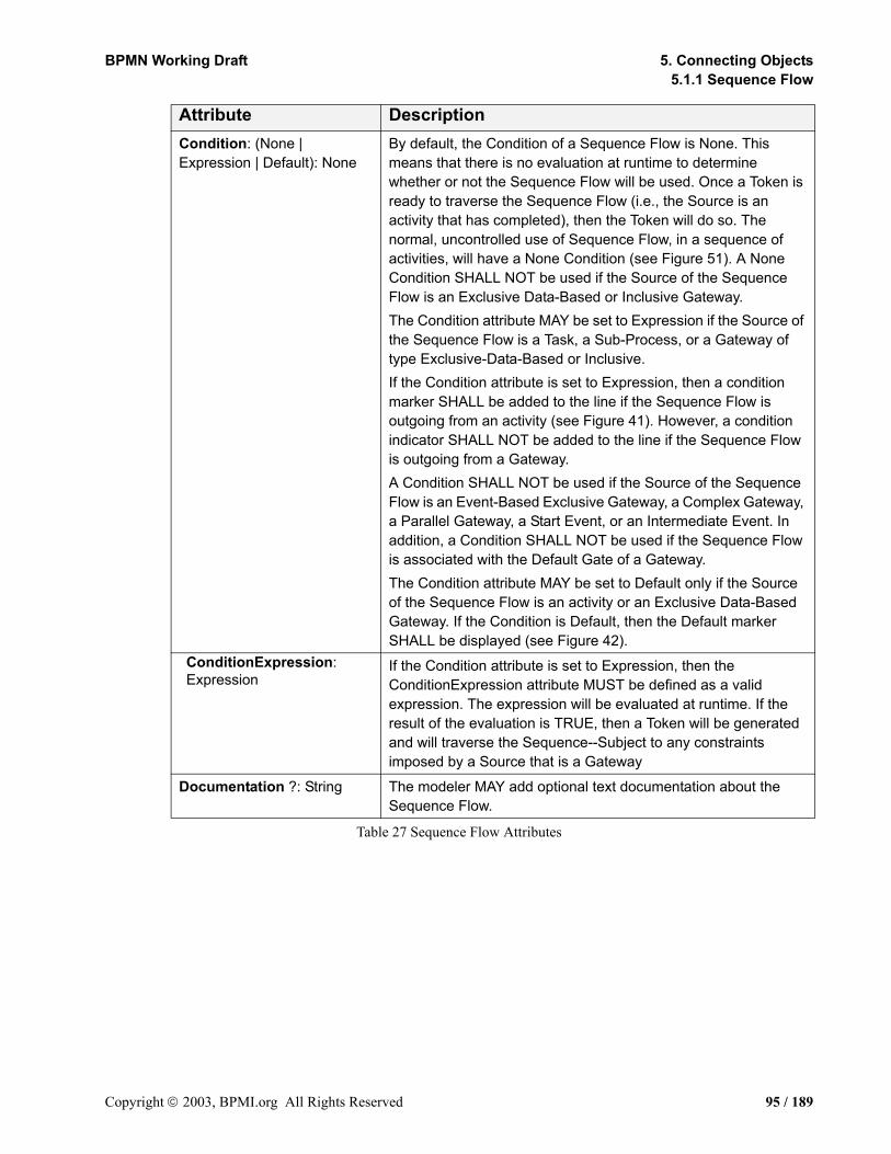
BPMN Working Draft 5. Connecting Objects5.1.1 Sequence Flow
Table 27 Sequence Flow Attributes
Condition: (None | Expression | Default): None
By default, the Condition of a Sequence Flow is None. This means that there is no evaluation at runtime to determine whether or not the Sequence Flow will be used. Once a Token is ready to traverse the Sequence Flow (i.e., the Source is an activity that has completed), then the Token will do so. The normal, uncontrolled use of Sequence Flow, in a sequence of activities, will have a None Condition (see Figure 51). A None Condition SHALL NOT be used if the Source of the Sequence Flow is an Exclusive Data-Based or Inclusive Gateway.The Condition attribute MAY be set to Expression if the Source of the Sequence Flow is a Task, a Sub-Process, or a Gateway of type Exclusive-Data-Based or Inclusive. If the Condition attribute is set to Expression, then a condition marker SHALL be added to the line if the Sequence Flow is outgoing from an activity (see Figure 41). However, a condition indicator SHALL NOT be added to the line if the Sequence Flow is outgoing from a Gateway.A Condition SHALL NOT be used if the Source of the Sequence Flow is an Event-Based Exclusive Gateway, a Complex Gateway, a Parallel Gateway, a Start Event, or an Intermediate Event. In addition, a Condition SHALL NOT be used if the Sequence Flow is associated with the Default Gate of a Gateway.The Condition attribute MAY be set to Default only if the Source of the Sequence Flow is an activity or an Exclusive Data-Based Gateway. If the Condition is Default, then the Default marker SHALL be displayed (see Figure 42).
ConditionExpression: Expression
If the Condition attribute is set to Expression, then the ConditionExpression attribute MUST be defined as a valid expression. The expression will be evaluated at runtime. If the result of the evaluation is TRUE, then a Token will be generated and will traverse the Sequence--Subject to any constraints imposed by a Source that is a Gateway
Documentation ?: String The modeler MAY add optional text documentation about the Sequence Flow.
Attribute Description
Copyright 2003, BPMI.org All Rights Reserved 95 / 189

5.1 Graphical Connecting Objects BPMN Working Draft5.1.2 Message Flow
5.1.2 Message FlowA Message Flow is used to show the flow of messages between two entities that are prepared to send and receive them. In BPMN, two separate Pools in the Diagram will represent the two entities. Thus,
Message Flow MUST connect two Pools, either to the Pools themselves or to flow objects within the Pools. They cannot connect two objects within the same Pool.
A Message Flow is line with a open arrowhead that MUST be drawn with a dashed single black line (as seen in Figure 43).
The use of text, color, size, and lines for a Message Flow MUST follow the rules defined in section 3.3 on page 34.
Figure 43 A Message Flow
The Message Flow can connect directly to the boundary of a Pool (See Figure 44),
especially if the Pool does not have any process details within (e.g., is a “Black Box”).
Figure 44 Message Flow connecting to the boundaries of two Pools
Man
ufac
ture
rFi
nanc
ial
Inst
itutio
n
Credit ResponseCredit Request
96 / 189 Copyright 2003, BPMI.org All Rights Reserved

BPMN Working Draft 5. Connecting Objects5.1.2 Message Flow
A Message Flow can also cross the boundary of a Pool and connect to a flow object within that Pool (see Figure 45).
Figure 45 Message Flow connecting to flow objects within two Pools
+
Credit CardAuthorization
Fina
ncia
lIn
stitu
tion
AuthorizePayment
Pack Goods Ship Goods
Process Order
+
Dis
tribu
tion
Sale
s
Supp
lier
Copyright 2003, BPMI.org All Rights Reserved 97 / 189

5.1 Graphical Connecting Objects BPMN Working Draft5.1.2 Message Flow
If there is an Expanded Sub-Process in one of the Pools, then the message flow can be connected to either the boundary of the Sub-Process or to objects within the Sub-Process. If the Message Flow is connected to the boundary to the Expanded Sub-Process, then this is equivalent to connecting to the Start Event for incoming Message Flows or the End Event for outgoing Message Flows (see Figure 46).
Figure 46 Message Flow connecting to boundary of Sub-Process and Internal objects
Cus
tom
er
Credit Response
Credit Report
Type ofCustomer?
Default(New)
Established withgood Credit
Established withpoor Credit
Include ApologyText
Include History ofTransactions
Include StandardTextReceive Credit
Report
Check Credit
Sup
plie
r
Recieve Request
Credit Request
Cre
dit
Age
ncy
No
Approve?
Default(Yes)
Continue Order...
98 / 189 Copyright 2003, BPMI.org All Rights Reserved

BPMN Working Draft 5. Connecting Objects5.1.3 Association
AttributesThe following table displays the identified attributes of a Message Flow (Note that this is the complete set and it does not extend the set of common object attributes):
Table 28 Message Flow Attributes
5.1.3 AssociationAn Association is used to associate information and artifacts with flow objects. Text and graphical non-flow objects can be associated with the flow objects and flows. An Association is also used to show the activities used to compensate for an activity. More information about compensation can be found in the section entitled “Compensation Association” on page 124.
A Message Flow is line that MUST be drawn with a dotted single black line (as seen in Figure 47).
The use of text, color, size, and lines for a Message Flow MUST follow the rules defined in section 3.3 on page 34.
Figure 47 An Association
If there is a reason to put directionality on the association then:
A line arrowhead MAY be added to the Association line. (see Figure 48).
Attribute DescriptionId: String This is a unique ID that identifies the Message Flow from other
objects within the Diagram.
Name ?: String Name is an optional attribute that is text description of the Message Flow.
Message ?: MessageName Message is an optional attribute that identifies the Message that is being sent.
Source: ObjectId Source is an attribute that identifies the object the Message Flow is connected from; i.e., the Message Flow is an outgoing flow from that object. The Message Flow MAY originate from the boundary of the Pool or an object within the Pool. If the source is an object within the Pool, then the ObjectName MUST identify the Pool and the Object.
Target: ObjectId Target is an attribute that identifies the object the Message Flow is connected to; i.e., the Message Flow is an incoming flow to that object. The Message Flow MAY target the boundary of the Pool or an object within the Pool. If the target is an object within the Pool, then the ObjectName MUST identify the Pool and the Object.
Documentation ? The modeler MAY add optional text documentation about the Message Flow.
Copyright 2003, BPMI.org All Rights Reserved 99 / 189
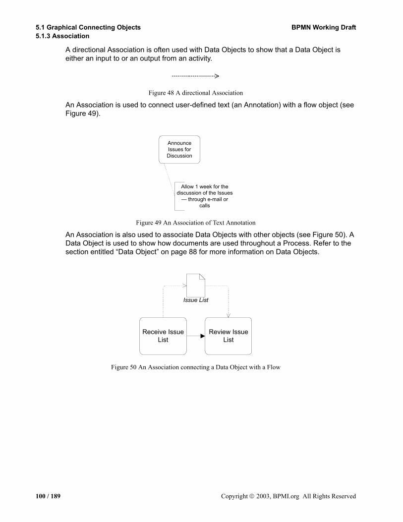
5.1 Graphical Connecting Objects BPMN Working Draft5.1.3 Association
A directional Association is often used with Data Objects to show that a Data Object is either an input to or an output from an activity.
Figure 48 A directional Association
An Association is used to connect user-defined text (an Annotation) with a flow object (see Figure 49).
Figure 49 An Association of Text Annotation
An Association is also used to associate Data Objects with other objects (see Figure 50). A Data Object is used to show how documents are used throughout a Process. Refer to the section entitled “Data Object” on page 88 for more information on Data Objects.
Figure 50 An Association connecting a Data Object with a Flow
AnnounceIssues forDiscussion
Allow 1 week for thediscussion of the Issues
— through e-mail orcalls
Review IssueList
Receive IssueList
Issue List
100 / 189 Copyright 2003, BPMI.org All Rights Reserved

BPMN Working Draft 5. Connecting Objects5.1.3 Association
AttributesThe following table displays the identified attributes of a Association (Note that this is the complete set and it does not extend the set of common object attributes):
Table 29 Association Attributes
5.2 Sequence Flow MechanismsThe Sequence Flow mechanisms described in the following sections are divided into four types: Normal, Exception, Link Events, and Ad Hoc (no flow). Within these types of flow, BPMN can be related to specific “Workflow Patterns1.” These patterns began as development work by Wil van der Aalst2, a professor at the Eindhoven University of Technology, and Arthur ter Hofstede3, an associate professor at the Queensland University of Technology. Twenty-one patterns have been defined as a way to document specific behavior that can be executed by a BPM system. These patterns range from very simple behavior to very complex business behavior. These patterns are useful in that they provide a comprehensive checklist of behavior that should be accounted for by BPM system. Therefore, some of these patterns will be illustrated with BPMN in the following sections to show how BPMN can handle the simple and complex requirements for Business Process Modeling.
Attribute DescriptionId: String This is a unique ID that identifies the Association from other
objects within the Diagram.
Name ?: String Name is an optional attribute that is text description of the Association.
Source: ObjectId Source is an attribute that identifies which object the Association is connected from. The set of objects that an Association MAY connect to are: Pool, Lane, all Events, Task, Sub-Process, Gateway, Sequence Flow, and Message Flow.
Target: ObjectId Target is an attribute that identifies which object the Association is connected to. Associations MUST only connect to Artifacts or Compensation Activities.
Direction (None | To | From | Both): None
Direction is an attribute that defines whether or not the Association shows any directionality with an arrowhead. The default is None (no arrowhead). A value of To means that the arrowhead SHALL be at the Source object. A value of From means that the arrowhead SHALL be at the Target artifact. A value of Both means that there SHALL be an arrowhead at both ends of the Association line.
Documentation ? The modeler MAY add optional text documentation about the Association.
1.http://tmitwww.tm.tue.nl/research/patterns/2.http://tmitwww.tm.tue.nl/staff/wvdaalst/3.http://sky.fit.qut.edu.au/~terhofst/
Copyright 2003, BPMI.org All Rights Reserved 101 / 189

5.2 Sequence Flow Mechanisms BPMN Working Draft5.2.1 Normal Flow
5.2.1 Normal FlowNormal Sequence Flow refers to the flow that originates from a Start Event and continues through activities via alternative and parallel paths until it ends at an End Event. The simplest type of flow within a Process is a sequence, which defines a dependencies of order for a series of activities that will be performed (serially). A sequence is also Workflow Pattern #1 -- Sequence1 (see Figure 51).
Figure 51 Workflow Pattern #1: Sequence
As stated previously, the normal Sequence Flow should be completely exposed and no flow behavior hidden. This means that a viewer of a BPMN Diagram will be able to trace through a series of flow objects and Sequence Flows, from the beginning to the end of a given level of the Process without any gaps or hidden “jumps” (see Figure 52). In this figure, Sequence Flows connect all the objects in the Diagram, from the Start Event to the End Event. The behavior of the Process shown will reflect the connections as shown and not skip any activities or “jump” to the end of the Process.
Figure 52 A Process with Normal flow
As the Process continues through the series of Sequence Flows, control mechanisms may divide or combine the Sequence Flows as a means of describing complex behavior. There are control mechanisms for dividing (forking and splitting) and for combining (joining and merging) Sequence Flows. Gateways and conditional Sequence Flow are used to accomplish the dividing and combining of flow. It is possible that there may be gaps in the Sequence Flow if Gateways and/or conditional Sequence Flow are not configured to cover all performance possibilities. In this case, a model that violates the flow traceability requirement will be considered an invalid model. Presumably, process development software or BPM test environments will be able to test a process model to ensure that the model is valid.
A casual look at the definitions of the English terms for these mechanisms (e.g., forking and splitting) would indicate that each pair of terms mean basically the same thing. However,
1. http://tmitwww.tm.tue.nl/research/patterns/sequence.htm
A B C
Ship Order
Send Invoice Make Payment
Receive Order
Fill Order
Accepted orRejected?
Accepted
Accept Payment
Close Order
Rejected
102 / 189 Copyright 2003, BPMI.org All Rights Reserved
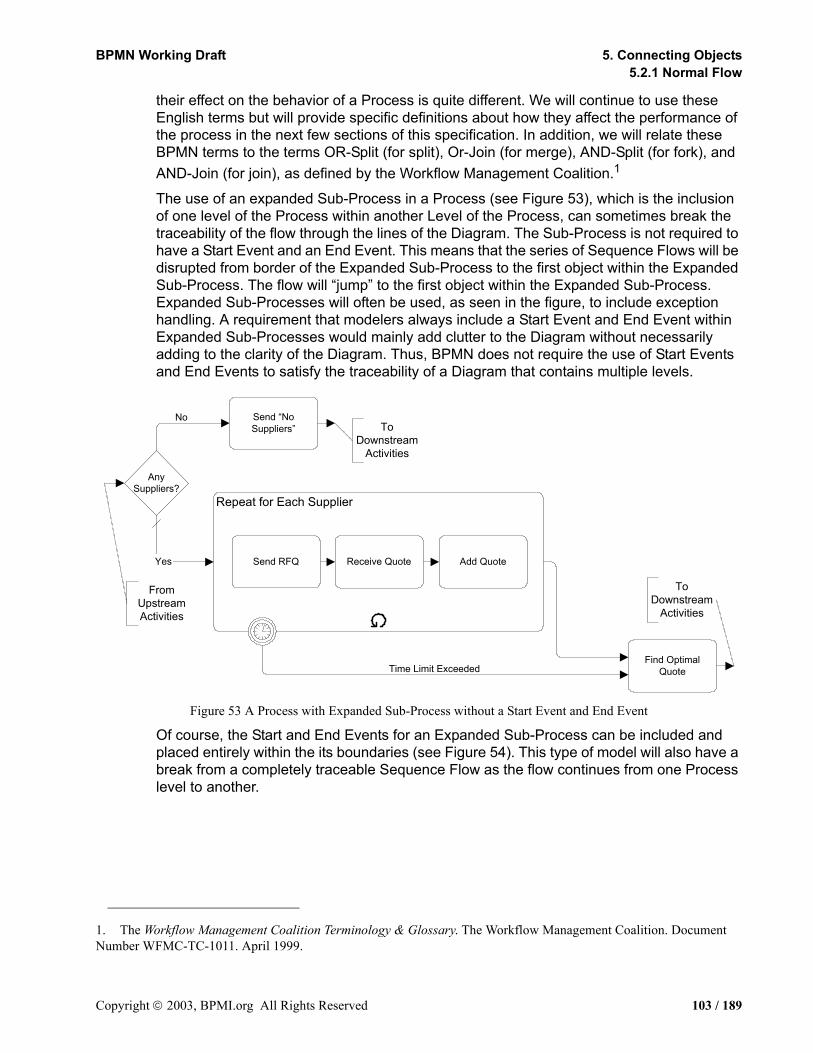
BPMN Working Draft 5. Connecting Objects5.2.1 Normal Flow
their effect on the behavior of a Process is quite different. We will continue to use these English terms but will provide specific definitions about how they affect the performance of the process in the next few sections of this specification. In addition, we will relate these BPMN terms to the terms OR-Split (for split), Or-Join (for merge), AND-Split (for fork), and AND-Join (for join), as defined by the Workflow Management Coalition.1
The use of an expanded Sub-Process in a Process (see Figure 53), which is the inclusion of one level of the Process within another Level of the Process, can sometimes break the traceability of the flow through the lines of the Diagram. The Sub-Process is not required to have a Start Event and an End Event. This means that the series of Sequence Flows will be disrupted from border of the Expanded Sub-Process to the first object within the Expanded Sub-Process. The flow will “jump” to the first object within the Expanded Sub-Process. Expanded Sub-Processes will often be used, as seen in the figure, to include exception handling. A requirement that modelers always include a Start Event and End Event within Expanded Sub-Processes would mainly add clutter to the Diagram without necessarily adding to the clarity of the Diagram. Thus, BPMN does not require the use of Start Events and End Events to satisfy the traceability of a Diagram that contains multiple levels.
Figure 53 A Process with Expanded Sub-Process without a Start Event and End Event
Of course, the Start and End Events for an Expanded Sub-Process can be included and placed entirely within the its boundaries (see Figure 54). This type of model will also have a break from a completely traceable Sequence Flow as the flow continues from one Process level to another.
1. The Workflow Management Coalition Terminology & Glossary. The Workflow Management Coalition. Document Number WFMC-TC-1011. April 1999.
Receive Quote Add QuoteSend RFQ
AnySuppliers?
Yes
Find OptimalQuote
No Send “NoSuppliers”
Repeat for Each Supplier
Time Limit Exceeded
FromUpstreamActivities
ToDownstream
Activities
ToDownstream
Activities
Copyright 2003, BPMI.org All Rights Reserved 103 / 189
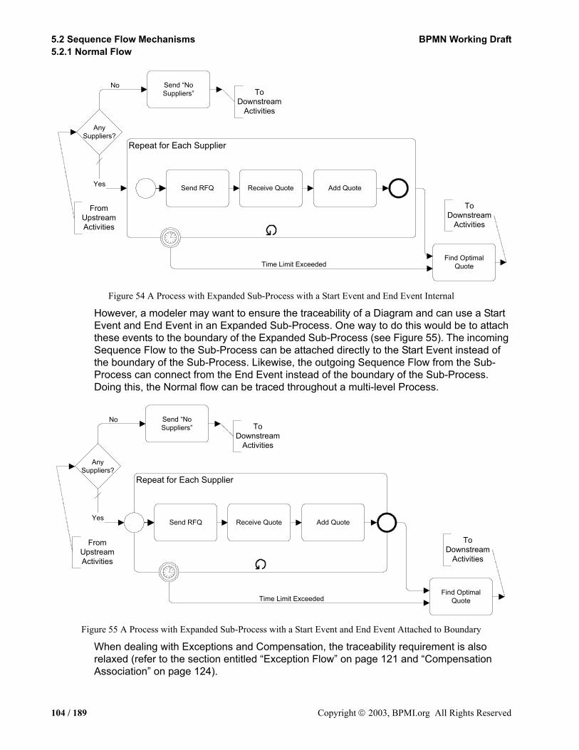
5.2 Sequence Flow Mechanisms BPMN Working Draft5.2.1 Normal Flow
Figure 54 A Process with Expanded Sub-Process with a Start Event and End Event Internal
However, a modeler may want to ensure the traceability of a Diagram and can use a Start Event and End Event in an Expanded Sub-Process. One way to do this would be to attach these events to the boundary of the Expanded Sub-Process (see Figure 55). The incoming Sequence Flow to the Sub-Process can be attached directly to the Start Event instead of the boundary of the Sub-Process. Likewise, the outgoing Sequence Flow from the Sub-Process can connect from the End Event instead of the boundary of the Sub-Process. Doing this, the Normal flow can be traced throughout a multi-level Process.
Figure 55 A Process with Expanded Sub-Process with a Start Event and End Event Attached to Boundary
When dealing with Exceptions and Compensation, the traceability requirement is also relaxed (refer to the section entitled “Exception Flow” on page 121 and “Compensation Association” on page 124).
AnySuppliers?
Yes
Find OptimalQuote
No Send “NoSuppliers”
Time Limit Exceeded
FromUpstreamActivities
ToDownstream
Activities
ToDownstream
Activities
Repeat for Each Supplier
Receive Quote Add QuoteSend RFQ
AnySuppliers?
Yes
Find OptimalQuote
No Send “NoSuppliers”
Time Limit Exceeded
FromUpstreamActivities
ToDownstream
Activities
ToDownstream
Activities
Receive Quote Add QuoteSend RFQ
Repeat for Each Supplier
104 / 189 Copyright 2003, BPMI.org All Rights Reserved

BPMN Working Draft 5. Connecting Objects5.2.1 Normal Flow
Forking FlowBPMN uses the term forking to refer to the dividing of a path into two or more parallel paths (also known as an AND-Split). It is a mechanism that will allow activities to be performed concurrently, rather than serially. This is also Workflow Pattern #2 -- Parallel Split1. BPMN provides three configurations that provide forking.
The first mechanism to create a fork is simple: a flow object can have two or more outgoing Sequence Flows (see Figure 56). A special flow control object is not used to fork the path in this case, since it is considered uncontrolled flow; that is, flow will proceed down each path without any dependencies or conditions--there is no Gateway that controls the flow. Forking Sequence Flow can be generated from a Task, Sub-Process, or a Start Event.
Figure 56 Workflow Pattern #2: Parallel Split -- Version 1
The second mechanism uses a Parallel Gateway (see Figure 60). For situations as shown in the Figure 57, a Gateway is not needed, since the same behavior can be created through multiple outgoing Sequence Flow, as in Figure 56. However, some modelers and modeling tools may use a forking Gateway as a “best practice.” Refer to the section entitled “Parallel Gateways (AND)” on page 81 for more information on Parallel Gateways.
Figure 57 Workflow Pattern #2: Parallel Split -- Version 2
Even when not required as a “best practice,” there are situations were the Parallel Gateway provides a useful indicator of the behavior of the Process. Figure 58 shows how a forking Gateway is used when the output of an Exclusive Decision requires that multiple activities will be performed based on one condition (Gate).
1. http://tmitwww.tm.tue.nl/research/patterns/parallel_split.htm
B
C
A
Parallel SplitUncontrolled Flow
B
C
A
Parallel SplitForking
Gateway
Copyright 2003, BPMI.org All Rights Reserved 105 / 189
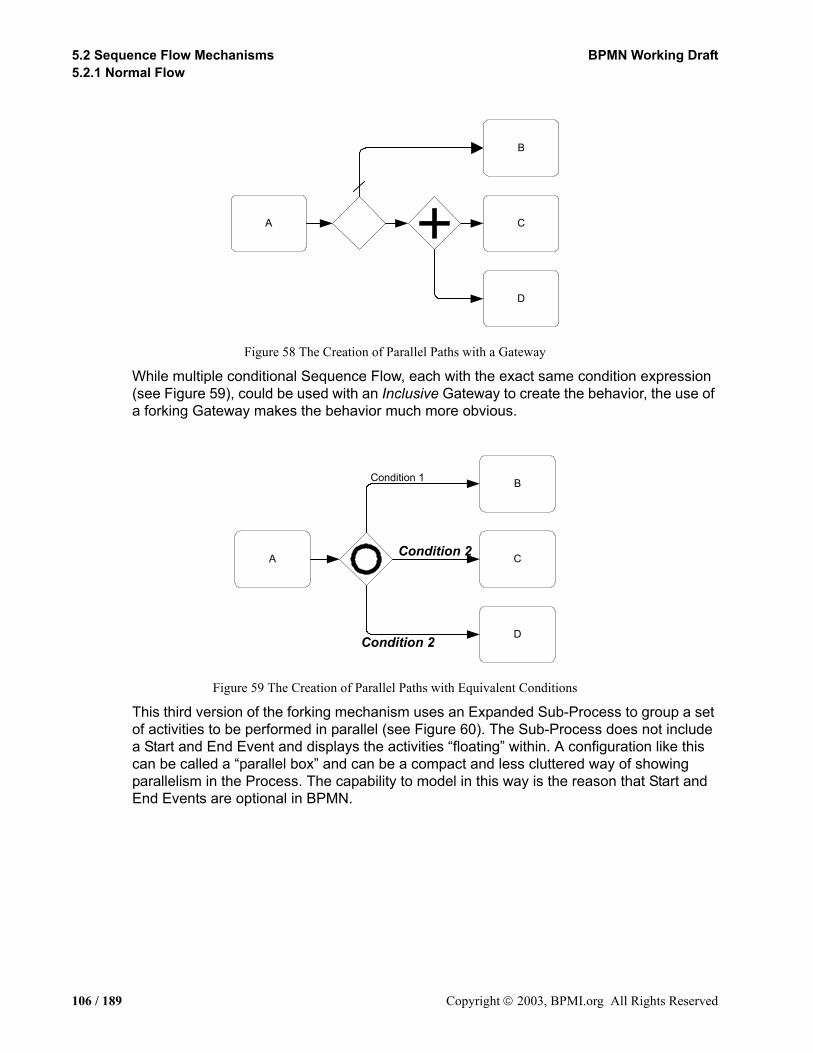
5.2 Sequence Flow Mechanisms BPMN Working Draft5.2.1 Normal Flow
Figure 58 The Creation of Parallel Paths with a Gateway
While multiple conditional Sequence Flow, each with the exact same condition expression (see Figure 59), could be used with an Inclusive Gateway to create the behavior, the use of a forking Gateway makes the behavior much more obvious.
Figure 59 The Creation of Parallel Paths with Equivalent Conditions
This third version of the forking mechanism uses an Expanded Sub-Process to group a set of activities to be performed in parallel (see Figure 60). The Sub-Process does not include a Start and End Event and displays the activities “floating” within. A configuration like this can be called a “parallel box” and can be a compact and less cluttered way of showing parallelism in the Process. The capability to model in this way is the reason that Start and End Events are optional in BPMN.
C
D
B
A
C
D
B
A
Condition 2
Condition 2
Condition 1
106 / 189 Copyright 2003, BPMI.org All Rights Reserved

BPMN Working Draft 5. Connecting Objects5.2.1 Normal Flow
Figure 60 Workflow Pattern #2: Parallel Split -- Version 3
Most of the time, the paths that have been divided with a fork are combined back together through a join (refer to the next section) and synchronized before the flow will continue. However, BPMN provides the flexibility for advanced methods to handle complex process situations. Thus, the exact behavior will be determined by the configuration of the Sequence Flow and the Gateways that are used.
Joining FlowBPMN uses the term joining to refer to the combining of two or more parallel paths into one path (also known as an AND-Join). A Parallel Gateway is used to synchronize two or more incoming Sequence Flows (see Figure 61). In general, this means that Tokens created at a fork will travel down parallel paths and then meet at the Parallel Gateway. From there, only one Token will continue. This is also Workflow Pattern #3 -- Synchronization1. Refer to the section entitled “Parallel Gateways (AND)” on page 81 for more information on Parallel Gateways.
Figure 61 Workflow Pattern #3: Synchronization -- Version 1
Another mechanism for synchronization is the completion of a Sub-Process (see Figure 62). If there are parallel paths within the Sub-Process that are not synchronized with an Parallel Gateway, then they will eventually reach an End Event (even if the End Event is implied). The default behavior of a Sub-Process is to wait until all activity within has been completed before the flow will move back up to a higher level Process. Thus, the completion of a Sub-Process is a synchronization point.
1. http://tmitwww.tm.tue.nl/research/synchronization.htm
B
C
A
Parallel SplitUncontrolled Flow
Applies to StartEvents
C
D
F
Copyright 2003, BPMI.org All Rights Reserved 107 / 189
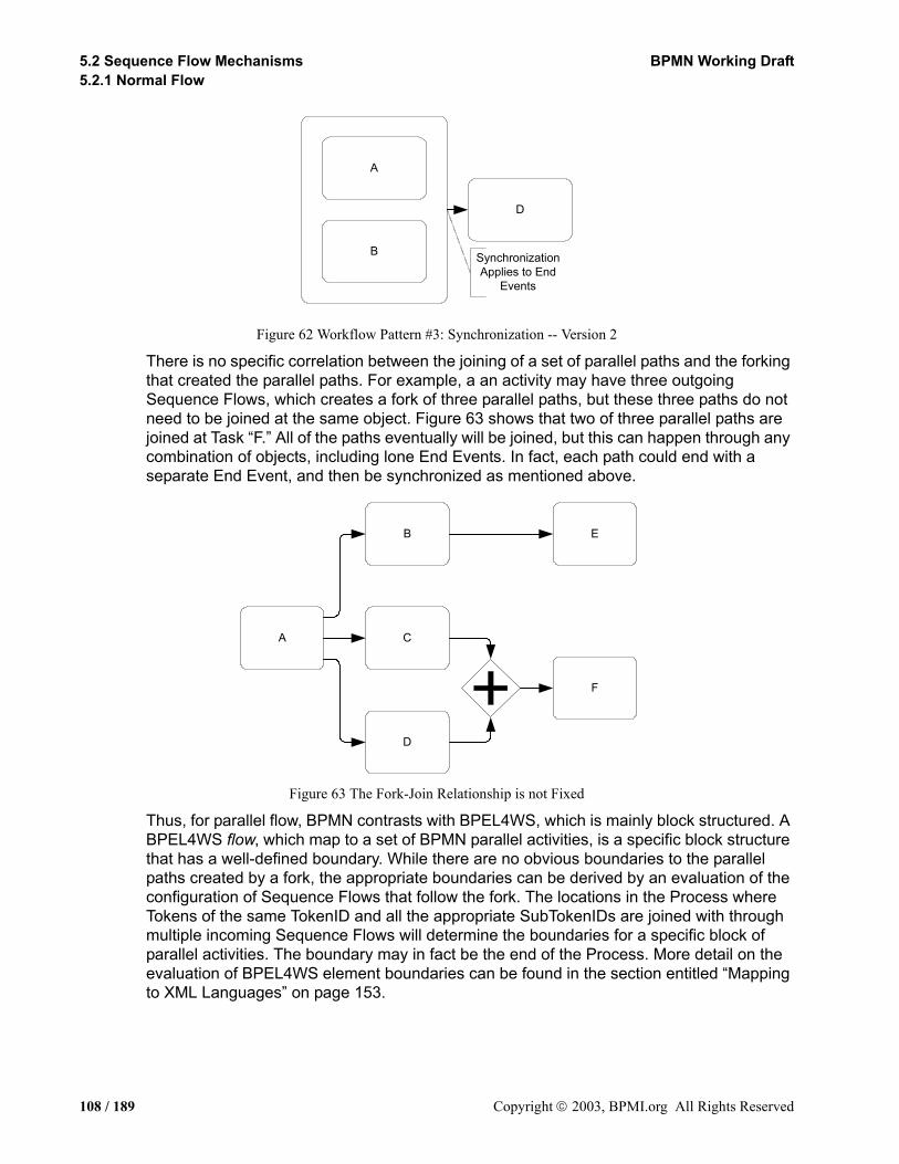
5.2 Sequence Flow Mechanisms BPMN Working Draft5.2.1 Normal Flow
Figure 62 Workflow Pattern #3: Synchronization -- Version 2
There is no specific correlation between the joining of a set of parallel paths and the forking that created the parallel paths. For example, a an activity may have three outgoing Sequence Flows, which creates a fork of three parallel paths, but these three paths do not need to be joined at the same object. Figure 63 shows that two of three parallel paths are joined at Task “F.” All of the paths eventually will be joined, but this can happen through any combination of objects, including lone End Events. In fact, each path could end with a separate End Event, and then be synchronized as mentioned above.
Figure 63 The Fork-Join Relationship is not Fixed
Thus, for parallel flow, BPMN contrasts with BPEL4WS, which is mainly block structured. A BPEL4WS flow, which map to a set of BPMN parallel activities, is a specific block structure that has a well-defined boundary. While there are no obvious boundaries to the parallel paths created by a fork, the appropriate boundaries can be derived by an evaluation of the configuration of Sequence Flows that follow the fork. The locations in the Process where Tokens of the same TokenID and all the appropriate SubTokenIDs are joined with through multiple incoming Sequence Flows will determine the boundaries for a specific block of parallel activities. The boundary may in fact be the end of the Process. More detail on the evaluation of BPEL4WS element boundaries can be found in the section entitled “Mapping to XML Languages” on page 153.
A
B
D
SynchronizationApplies to End
Events
B
C
D
F
E
A
108 / 189 Copyright 2003, BPMI.org All Rights Reserved

BPMN Working Draft 5. Connecting Objects5.2.1 Normal Flow
Splitting FlowBPMN uses the term splitting to refer to the dividing of a path into two or more alternative paths (also known as an OR-Split). It is a place in the Process where a question is asked, and the answer determines which of a set of paths is taken. It is the “fork in the road” where a traveler, in this case a Token, can take only one of the forks (not to be confused with forking—see below).
The general concept of splitting the flow is usually referring to as a Decision. In traditional flow charting methodologies, Decisions are depicted as diamonds and usually are exclusive. BPMN also uses a diamond to leverage the familiarity of the shape, but extends the use of the diamond to handle the complex behavior of business processes (which cannot be handled by traditional flow charts). The diamond shape is used in both Gateways and the beginning of a conditional Sequence Flow (when exiting an activity). Thus, when readers of BPD sees a diamond, they know that the flow will be controlled in some way and will not just pass from one activity to another. The location of the mini-diamond and the internal indicators within the Gateways will indicate how the flow will be controlled.
There are multiple configurations to split the flow within BPMN so that different types of complex behavior can be modeled. Conditional Sequence Flow and three types of Gateways (Exclusive, Inclusive, and Complex) are used to split the flow. Refer to the section entitled “Sequence Flow” on page 93 for details on conditional Sequence Flow. Refer to the section entitled “Gateways” on page 64 for details on the Gateways.
There are two basic mechanism for making the Decision during the performance of the Process: the first is an evaluation of a condition expression. There are three variations of this mechanism: Exclusive, Inclusive, and Complex. The first variation, an Exclusive Decision, is the same as Workflow Pattern #4 -- Exclusive Choice1 (see Figure 64). Refer to the section entitled “Data-Based” on page 67 for more information on Data-Based Exclusive Gateways.
Figure 64 A Data-Based Decision Example -- Workflow Pattern #4 -- Exclusive Choice
1. http://tmitwww.tm.tue.nl/research/patterns/exclusive_choice.htm
DefaultCondition
Condition 2
Condition 1
Copyright 2003, BPMI.org All Rights Reserved 109 / 189
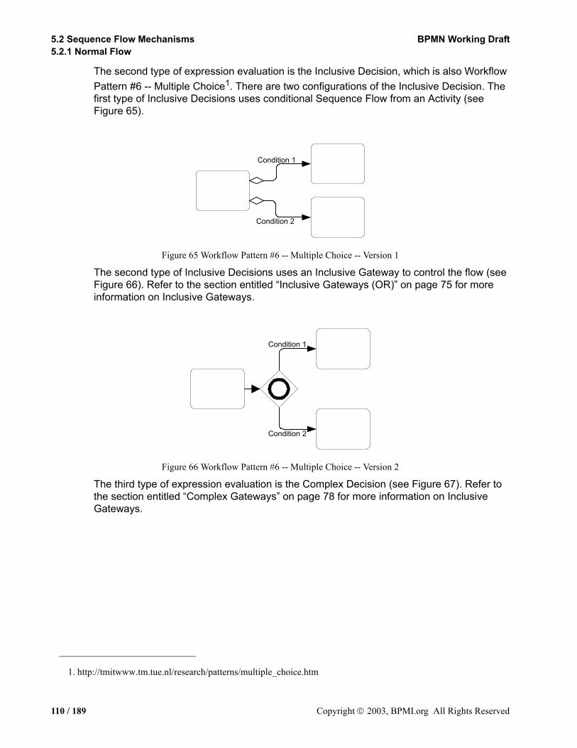
5.2 Sequence Flow Mechanisms BPMN Working Draft5.2.1 Normal Flow
The second type of expression evaluation is the Inclusive Decision, which is also Workflow Pattern #6 -- Multiple Choice1. There are two configurations of the Inclusive Decision. The first type of Inclusive Decisions uses conditional Sequence Flow from an Activity (see Figure 65).
Figure 65 Workflow Pattern #6 -- Multiple Choice -- Version 1
The second type of Inclusive Decisions uses an Inclusive Gateway to control the flow (see Figure 66). Refer to the section entitled “Inclusive Gateways (OR)” on page 75 for more information on Inclusive Gateways.
Figure 66 Workflow Pattern #6 -- Multiple Choice -- Version 2
The third type of expression evaluation is the Complex Decision (see Figure 67). Refer to the section entitled “Complex Gateways” on page 78 for more information on Inclusive Gateways.
1. http://tmitwww.tm.tue.nl/research/patterns/multiple_choice.htm
Condition 1
Condition 2
Condition 2
Condition 1
110 / 189 Copyright 2003, BPMI.org All Rights Reserved

BPMN Working Draft 5. Connecting Objects5.2.1 Normal Flow
Figure 67 A Complex Decision (Gateway)
The second mechanism for making a Decision is the occurrence of a particular event, such as the receipt of a message (see Figure 68). Refer to the section entitled “Event-Based” on page 72 for more information on Event-Based Exclusive Gateways.
Figure 68 An Event-Based Decision Example
Merging FlowBPMN uses the term merging to refer to the combining of two or more alternative paths into one path (also known as an a OR-Join). It is a place in the process where two or more alternative paths begin to traverse activities that are common to each of the paths. Theoretically, each alternative path can be modeled separately to a completion (an End Event). However, merging allows the paths to overlap and avoids the duplication of activities that are common to the separate paths. For a given instance of the Process, a
Alternative 2
Alternative 1
Alternative 3
Alternative 4
DecisionOR-Split
Message 1
Message 2
A
B
C
D
1 Day
Copyright 2003, BPMI.org All Rights Reserved 111 / 189
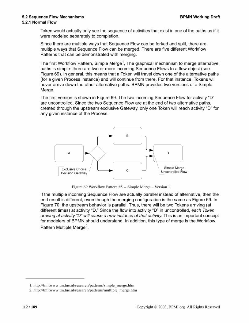
5.2 Sequence Flow Mechanisms BPMN Working Draft5.2.1 Normal Flow
Token would actually only see the sequence of activities that exist in one of the paths as if it were modeled separately to completion.
Since there are multiple ways that Sequence Flow can be forked and split, there are multiple ways that Sequence Flow can be merged. There are five different Workflow Patterns that can be demonstrated with merging.
The first Workflow Pattern, Simple Merge1, The graphical mechanism to merge alternative paths is simple: there are two or more incoming Sequence Flows to a flow object (see Figure 69). In general, this means that a Token will travel down one of the alternative paths (for a given Process instance) and will continue from there. For that instance, Tokens will never arrive down the other alternative paths. BPMN provides two versions of a Simple Merge.
The first version is shown in Figure 69. The two incoming Sequence Flow for activity “D” are uncontrolled. Since the two Sequence Flow are at the end of two alternative paths, created through the upstream exclusive Gateway, only one Token will reach activity “D” for any given instance of the Process.
Figure 69 Workflow Pattern #5 -- Simple Merge – Version 1
If the multiple incoming Sequence Flow are actually parallel instead of alternative, then the end result is different, even though the merging configuration is the same as Figure 69. In Figure 70, the upstream behavior is parallel. Thus, there will be two Tokens arriving (at different times) at activity “D.” Since the flow into activity “D” in uncontrolled, each Token arriving at activity “D” will cause a new instance of that activity. This is an important concept for modelers of BPMN should understand. In addition, this type of merge is the Workflow Pattern Multiple Merge2.
1. http://tmitwww.tm.tue.nl/research/patterns/simple_merge.htm2. http://tmitwww.tm.tue.nl/research/patterns/multiple_merge.htm
B
C
D
Simple MergeUncontrolled Flow
A
Exclusive ChoiceDecision Gateway
112 / 189 Copyright 2003, BPMI.org All Rights Reserved

BPMN Working Draft 5. Connecting Objects5.2.1 Normal Flow
Figure 70 Workflow Pattern #7 -- Multiple Merge
The second version of the Simple Merge is shown in Figure 71. The two incoming Sequence Flow for activity “D” are controlled through the Exclusive Gateway. Since the two Sequence Flow are at the end of two alternative paths, created through the upstream exclusive Gateway, only one Token will reach the Gateway for any given instance of the Process. The Token will then immediately proceed to activity “D.”
Figure 71 Workflow Pattern #5 -- Simple Merge – Version 2
Again, if the multiple incoming Sequence Flow are actually parallel instead of alternative, then the end result is different, even though the merging configuration is the same as Figure 71. In the model shown in Figure 72, there will be two Tokens arriving (at different times) at the Exclusive Gateway preceding activity “D.” In this situation, the Gateway will accept the first Token and immediately pass it on through to the activity. When the second Token arrives, it will be excluded from the remainder of the flow. This means that the Token will not be passed on to the activity, but will be consumed. This type of merge is the Workflow Pattern Discriminator1.
1. http://tmitwww.tm.tue.nl/research/patterns/discriminator.htm
D
Multiple MergeUncontrolled Flow
B
C
A
Parallel SplitUncontrolled Flow
B
C
D
Simple MergeMergingGateway
Version 2
A
Exclusive ChoiceDecision Gateway
Copyright 2003, BPMI.org All Rights Reserved 113 / 189

5.2 Sequence Flow Mechanisms BPMN Working Draft5.2.1 Normal Flow
Figure 72 Workflow Pattern #8 -- Discriminator
The fourth type of Workflow Pattern merge is called a Synchronizing Join1. This is a situation when the merging location does not know ahead of time how many Tokens will be arriving at the Gateway. In some Process instances, there may be only one Token. In other Process instances, there may be more than one Token arriving. This type of situation is created when an Inclusive Decision is made up stream (see Figure 73). To handle this, an Inclusive Gateway can be used to merge the appropriate number of Tokens for each Process instance. The Gateway, following the pattern Synchronizing Join, will wait for all expected Tokens before the flow will continue to the next activity. Refer to the section entitled “Inclusive Gateways (OR)” on page 75 for more information on Inclusive Gateways.
Figure 73 Workflow Pattern #9 -- Synchronizing Join
1. http://tmitwww.tm.tue.nl/research/patterns/synchronizing_join.htm
B
C
A
Parallel SplitUncontrolled Flow
D
DiscriminatorMergingGateway
B
C
D
Synchronizing MergeMerging Gateway
A
Multi-ChoiceInclusive Decision
Gateway
114 / 189 Copyright 2003, BPMI.org All Rights Reserved

BPMN Working Draft 5. Connecting Objects5.2.1 Normal Flow
The fourth type of Workflow Pattern merge is called a N out of M Join1. This type of situation is more complex and can be handled through a Complex Gateway (see Figure 74). The Gateway will receive Tokens from its incoming Sequence Flow and evaluate an expression to determine whether or not the flow should proceed. Once the condition has been satisfied, if additional Tokens arrive, then will be excluded (much like the Discriminator Pattern from Figure 72). Refer to the section entitled “Complex Gateways” on page 78 for more information on Inclusive Gateways.
Figure 74 Workflow Pattern #8 -- N out of M Join
There is no specific correlation between the merging of a set of paths and the splitting that occurs through a Gateway object. For example, a Decision may split a path into three separate paths, but these three paths do not need to be merged at the same object. Figure 75 shows that two of three alternative paths are merged at Task “F.” All of the paths eventually will be merged, but this can happen through any combination of objects, including lone End Events. In fact, each path could end with a separate End Event.
Figure 75 The Split-Merge Relationship is not Fixed
1. http://tmitwww.tm.tue.nl/research/patterns/n_out_of_m_join.htm
B1
B3
A
Parallel SplitUncontrolled Flow
B2 C
N out of M JoinComplexGateway
BCondition 1
[Default]
A C
D
Condition 2
E
F
Copyright 2003, BPMI.org All Rights Reserved 115 / 189

5.2 Sequence Flow Mechanisms BPMN Working Draft5.2.1 Normal Flow
Thus, for alternative flow, BPMN contrasts with BPEL4WS, which are mainly block structured. A BPEL4WS switch and pick, which map to the BPMN Decision, are specific block structures that have well-defined boundaries. While there are no obvious boundaries to the alternative paths created by a decision in BPMN, the appropriate boundaries can be derived by an evaluation of the configuration of Sequence Flows that follow the decision. The locations in the Process where Tokens of the same identity are merged through multiple incoming Sequence Flows will determine the boundaries for a specific decision. The boundary may in fact be the end of the Process. More detail on the evaluation of BPEL4WS element boundaries can be found in the section entitled “Mapping to XML Languages” on page 153.
LoopingBPMN provides 2 (two) mechanisms for looping within a Process. The first involves the use of attributes of activities to define the loop. The second involves the connection of Sequence Flows to “upstream” objects.
Activity LoopingThe attributes of Tasks and Sub-Processes will determine if they are repeated as a loop. There are two types of loops that can be specified: Standard and Multi-Instance.
For Standard Loops:
• If the loop condition is evaluated before the activity, this is generally referred to as a “while” loop. This means that the activities will be repeated as long as the condition is true. The activities may not be performed at all (if the condition is false the first time) or performed many times.
• If the loop condition is evaluated after the activity, this is generally referred to as an “until” loop. This means that the activities will be repeated until a condition becomes true. The activities will be performed at least once or performed many times.
For Multi-Instance Loops:
• If the InstanceGeneration is serial, then this becomes much like a while loop with a set number of iterations the loop will go through. These are often used in processes where a specific type of item will have a set number of sub-items or line items. A Multi-Instance loop will be used to process each of the line items.
• If the InstanceGeneration is parallel, this is generally referred to as a multiple instance of the activities. An example of this type of feature would be used in a process to write a book, there would be a Sub-Process to write a chapter. There would be as many copies or instances of the Sub-Process as there are chapters in the book. All the instances could begin at the same time.
Those activities that are repeated (looped) will have a loop marker placed in the bottom center of the activity shape (see Figure 76). Those activities that are Parallel Multi-Instance will have a parallel marker placed in the bottom center of the activity shape (see Figure 77)
116 / 189 Copyright 2003, BPMI.org All Rights Reserved

BPMN Working Draft 5. Connecting Objects5.2.1 Normal Flow
Figure 76 A Task and a Collapsed Sub-Process with a Loop Marker
Figure 77 A Task with a Parallel Marker
Expanded Sub-Processes also can have a loop marker placed at the bottom center of the Sub-Process rectangle (see Figure 78). The entire contents of the Sub-Process will be repeated as defined in the attributes.
Figure 78 An Expanded Sub-Process with a Loop Marker
Sequence Flow LoopingLoops can also be created by connecting a Sequence Flow to an “upstream” object. An object is considered to be upstream if that object has an outgoing Sequence Flow that leads to a series of other Sequence Flows, the last of which turns out to be an incoming Sequence Flow to the original object. That is, that object produces a Token and that Token traverses a set of Sequence Flows until the Token reaches the same object again. Sequence Flow looping is the same as Workflow Pattern #16 -- Arbitrary Cycle1 (see Figure 64).
1. http://tmitwww.tm.tue.nl/research/patterns/arbitrary_cycle.htm
Receive Vote Discussion Cycle
Request Quotes
Discussion Cycle (Until Discussion Over)
E-Mail DiscussionDeadline Warning
Delay 6 days fromAnnouncement
Announce Issuesfor Discussion
Review Status ofDiscussion
Moderate E-mailDiscussion
7 Days
Copyright 2003, BPMI.org All Rights Reserved 117 / 189
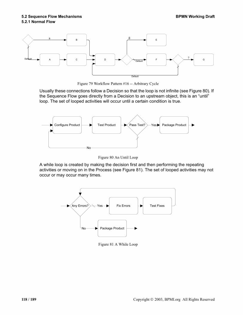
5.2 Sequence Flow Mechanisms BPMN Working Draft5.2.1 Normal Flow
Figure 79 Workflow Pattern #16 -- Arbitrary Cycle
Usually these connections follow a Decision so that the loop is not infinite (see Figure 80). If the Sequence Flow goes directly from a Decision to an upstream object, this is an “until” loop. The set of looped activities will occur until a certain condition is true.
Figure 80 An Until Loop
A while loop is created by making the decision first and then performing the repeating activities or moving on in the Process (see Figure 81). The set of looped activities may not occur or may occur many times.
Figure 81 A While Loop
?
ßa B
C DA
E
F GDefaultDefault
Default
No
Configure Product Test Product Package ProductPass Test? Yes
Yes Fix Errors Test Fixes
Package Product
Any Errors?
No
118 / 189 Copyright 2003, BPMI.org All Rights Reserved

BPMN Working Draft 5. Connecting Objects5.2.1 Normal Flow
Passing the Sequence Flow to and from Sub-ProcessesIf a Process is used within another Process, then it is a Sub-Process. The Sequence Flow will start at the parent Process and then pass to the Sub-Process and then will pass back to the parent process (see Figure 82). Most of the time the flow (a Token) will reach a Sub-Process, get transferred to the Start Event of the Sub-Process, traverse the Sequence Flows of the Sub-Process, reach the End Event of the Sub-Process, and, finally, get transferred back to the parent Process to continue. If the Sub-Process contains parallel flows, then all the flows must complete before the Token is transferred back to the parent Process. This functionality treats the Sub-Process as a self-contained “box” of activities.
Figure 82 Example of Sub-Process
Avoiding Illegal Models and Unexpected BehaviorBPMN, being a graph-structured Diagram, rather than having a block-structures like BPEL4WS, provides a great flexibility for depicting complex process behavior in a fairly compact form. However, the free-form nature of BPMN can create modeling situations that cannot be executed or will behave in a manner that is not expected by the modeler. These types of modeling problems can occur because there is not a tight relationship between forks and joins or splits and merges. A block structure provides these tight relationships, but a graph-structure allows these flow control mechanisms to be mixed and matched at the discretion of the modeler. Some combinations of these control elements will create Processes that cannot be executed or will create behavior that was not intended by the modeler. The situation where alternative paths cross the implicit boundary of a group of parallel paths can cause an invalid model.
Figure 83 shows such a model. Task “D” is an activity that has two incoming Sequence Flows; one from a forked path (after a split path) and one from a split path. This can create a problem at the Parallel Gateway that precedes Task “E,” which also has multiple incoming Sequence Flows. The Sequence Flow from Task “B” is crossing the implicit boundary of the fork created after Task “A.” As a result, if the “Yes” Sequence Flow is taken from the Decision in the Diagram (Variation 1), then Task “E” can expect two Tokens to arrive—one from Task “C” and one from Task “D.” However, if the “No” Sequence Flow is taken from the Decision (Variation 2), the Parallel Gateway will receive only one Token—one from Task
Include History ofTransactions
Include StandardText
Receive CreditReport
Check Credit
Recieve Request
No
Approve?
Continue Order...Yes
Copyright 2003, BPMI.org All Rights Reserved 119 / 189
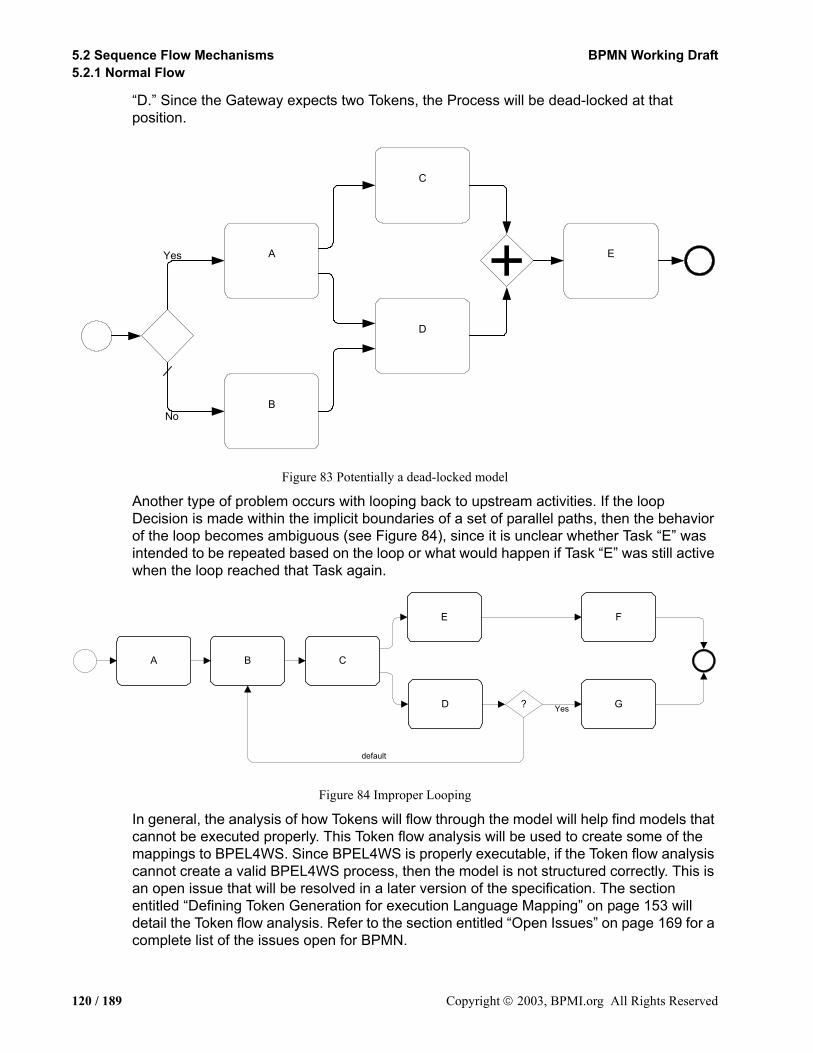
5.2 Sequence Flow Mechanisms BPMN Working Draft5.2.1 Normal Flow
“D.” Since the Gateway expects two Tokens, the Process will be dead-locked at that position.
Figure 83 Potentially a dead-locked model
Another type of problem occurs with looping back to upstream activities. If the loop Decision is made within the implicit boundaries of a set of parallel paths, then the behavior of the loop becomes ambiguous (see Figure 84), since it is unclear whether Task “E” was intended to be repeated based on the loop or what would happen if Task “E” was still active when the loop reached that Task again.
Figure 84 Improper Looping
In general, the analysis of how Tokens will flow through the model will help find models that cannot be executed properly. This Token flow analysis will be used to create some of the mappings to BPEL4WS. Since BPEL4WS is properly executable, if the Token flow analysis cannot create a valid BPEL4WS process, then the model is not structured correctly. This is an open issue that will be resolved in a later version of the specification. The section entitled “Defining Token Generation for execution Language Mapping” on page 153 will detail the Token flow analysis. Refer to the section entitled “Open Issues” on page 169 for a complete list of the issues open for BPMN.
A
B
C
D
EA
B
C
D
EYes
No
default
BA C
E
D ?
F
GYes
120 / 189 Copyright 2003, BPMI.org All Rights Reserved
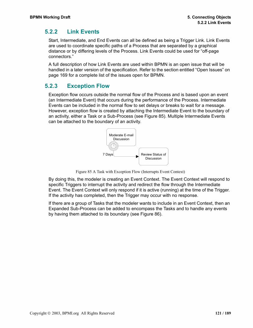
BPMN Working Draft 5. Connecting Objects5.2.2 Link Events
5.2.2 Link EventsStart, Intermediate, and End Events can all be defined as being a Trigger Link. Link Events are used to coordinate specific paths of a Process that are separated by a graphical distance or by differing levels of the Process. Link Events could be used for “off-page connectors.”
A full description of how Link Events are used within BPMN is an open issue that will be handled in a later version of the specification. Refer to the section entitled “Open Issues” on page 169 for a complete list of the issues open for BPMN.
5.2.3 Exception FlowException flow occurs outside the normal flow of the Process and is based upon an event (an Intermediate Event) that occurs during the performance of the Process. Intermediate Events can be included in the normal flow to set delays or breaks to wait for a message. However, exception flow is created by attaching the Intermediate Event to the boundary of an activity, either a Task or a Sub-Process (see Figure 85). Multiple Intermediate Events can be attached to the boundary of an activity.
Figure 85 A Task with Exception Flow (Interrupts Event Context)
By doing this, the modeler is creating an Event Context. The Event Context will respond to specific Triggers to interrupt the activity and redirect the flow through the Intermediate Event. The Event Context will only respond if it is active (running) at the time of the Trigger. If the activity has completed, then the Trigger may occur with no response.
If there are a group of Tasks that the modeler wants to include in an Event Context, then an Expanded Sub-Process can be added to encompass the Tasks and to handle any events by having them attached to its boundary (see Figure 86).
Review Status ofDiscussion
Moderate E-mailDiscussion
7 Days
Copyright 2003, BPMI.org All Rights Reserved 121 / 189

5.2 Sequence Flow Mechanisms BPMN Working Draft5.2.4 Ad Hoc
Figure 86 A Sub-Process with Exception Flow (Interrupts Event Context)
Two Triggers for Intermediate Event are used by Event Contexts at the level of the execution language (BPEL4WS): Message, and Exception (fault). A Message Event occurs when a message, with the exact identity as specified in the Intermediate Event, is received by the Process. An Exception Event occurs when the Process detects an Exception. If an Error Code is specified in the Intermediate Event, then the code of the detected Error must match for the Event Context to respond. If the Intermediate Event does not specify an Error Code, then any Exception will trigger a response from the Event Context. Other BPMN Triggers, such as a Timer, must be converted into a BPEL4WS configuration that will generate the appropriate Message or Exception.
If this event does not occur while the Event Context is ready, then the Process will continue through the normal flow as defined through the Sequence Flows.
Mapping to Execution LanguagesRefer to the section entitled “Exception Flow” on page 162 for more information about how Exception Flow maps to execution languages.
5.2.4 Ad HocAn Ad Hoc Process is a group of activities that have no pre-definable sequence relationships. A set of activities can be defined for the Process, but the sequence and number of performances for the activities is completely determined by the performers of the activities and cannot be defined beforehand.
A Sub-Process is marked as being an Ad Hoc with a “tilde” symbol placed at the bottom center of the Sub-Process shape (see Figure 87 and Figure 88). Activities within the Process are disconnected from each other. During execution of the Process, any one or more of the activities may be active and they can be performed in almost any order or frequency.
Receive Quote Add QuoteSend RFQ
AnySuppliers?
Yes
Find OptimalQuote
No Send “NoSuppliers”
Repeat for Each Supplier
Time Limit Exceeded
122 / 189 Copyright 2003, BPMI.org All Rights Reserved

BPMN Working Draft 5. Connecting Objects5.2.4 Ad Hoc
Figure 87 A Collapsed Ad Hoc Sub-Process
Figure 88 An Expanded Ad Hoc Sub-Process
The performers determine when activities will start, when they will end, what the next activity will be, and so on. Examples of the types of Processes that are Ad Hoc include computer code development (at a low level), sales support, and writing a book chapter. If we look at the details of writing a book chapter, we could see that the activities within this Process include: researching the topic, writing text, editing text, generating graphics, including graphics in the text, organizing references, etc. (see Figure 89). There may be some dependencies between Tasks in this Process, such as writing text before editing text, but there is not necessarily any correlation between an instance of writing text to an instance of editing text. Editing may occur infrequently and based on the text of many instances of the writing text Task.
Figure 89 An Ad Hoc Process for Writing a Book Chapter
It is a challenge for a BPM engine to monitor the status of Ad Hoc Processes, usually these kind of processes are handled through groupware applications (such as e-mail), but BPMN allows modeling of Processes that are not necessarily executable and should provide the mechanisms for those BPM engines that can follow an Ad Hoc Process. Given this, at some point, the Process will have completed and this can be determined by evaluating a
+~Name
Name
~
Wrting a Book Chapter
researchingthe topic writing text editing text
generatinggraphics
includinggraphics in
text
organizingreferences
~
Copyright 2003, BPMI.org All Rights Reserved 123 / 189
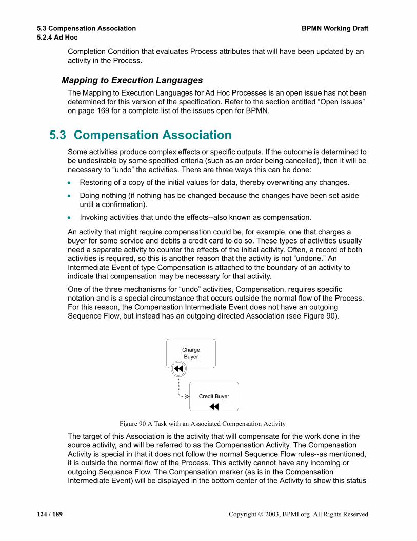
5.3 Compensation Association BPMN Working Draft5.2.4 Ad Hoc
Completion Condition that evaluates Process attributes that will have been updated by an activity in the Process.
Mapping to Execution LanguagesThe Mapping to Execution Languages for Ad Hoc Processes is an open issue has not been determined for this version of the specification. Refer to the section entitled “Open Issues” on page 169 for a complete list of the issues open for BPMN.
5.3 Compensation AssociationSome activities produce complex effects or specific outputs. If the outcome is determined to be undesirable by some specified criteria (such as an order being cancelled), then it will be necessary to “undo” the activities. There are three ways this can be done:
• Restoring of a copy of the initial values for data, thereby overwriting any changes.
• Doing nothing (if nothing has be changed because the changes have been set aside until a confirmation).
• Invoking activities that undo the effects--also known as compensation.
An activity that might require compensation could be, for example, one that charges a buyer for some service and debits a credit card to do so. These types of activities usually need a separate activity to counter the effects of the initial activity. Often, a record of both activities is required, so this is another reason that the activity is not “undone.” An Intermediate Event of type Compensation is attached to the boundary of an activity to indicate that compensation may be necessary for that activity.
One of the three mechanisms for “undo” activities, Compensation, requires specific notation and is a special circumstance that occurs outside the normal flow of the Process. For this reason, the Compensation Intermediate Event does not have an outgoing Sequence Flow, but instead has an outgoing directed Association (see Figure 90).
Figure 90 A Task with an Associated Compensation Activity
The target of this Association is the activity that will compensate for the work done in the source activity, and will be referred to as the Compensation Activity. The Compensation Activity is special in that it does not follow the normal Sequence Flow rules--as mentioned, it is outside the normal flow of the Process. This activity cannot have any incoming or outgoing Sequence Flow. The Compensation marker (as is in the Compensation Intermediate Event) will be displayed in the bottom center of the Activity to show this status
ChargeBuyer
Credit Buyer
124 / 189 Copyright 2003, BPMI.org All Rights Reserved

BPMN Working Draft 5. Connecting Objects5.2.4 Ad Hoc
of the activity (see the “Credit Buyer” Task in Figure 90). Note that there can be only one target activity for compensation. There cannot be a sequence of activities shown. If the compensation does require more than one activity, then these activities must be put inside a single Sub-Process that is the target of the Association. The Sub-Process can be collapsed or expanded. If the Sub-Process is expanded, then only the Sub-Process itself requires the Compensation marker--the activities inside the Sub-Process do not require this marker.
Only activities that have been completed can be compensated. The compensation of an activity can be triggered in two ways:
• The activity is inside a Transaction Sub-Process that is cancelled (see Figure 91). In this situation, the whole Sub-Process will be “rewound” or rolled back--the Process flow will go backwards and any activity that requires compensation will be compensated. This is why the Compensation marker for Events looks like a “rewind” symbol for a tape player. After the compensation has been completed, the Process will continue its rollback.
• A downstream Intermediate or End Event of type Compensation “throws” a compensation identifier that is “caught” by the Intermediate Event attached to the boundary of the activity.
Figure 91 Compensation Shown in the context of a Transaction
Bookings
Book Flight
Book Hotel
SendUnavailability
Notice
Cancel Flight
Send HotelCancellation
Transaction
SuccessfulBookings
FailedBookings
Exceptions(Hazards)
ChargeBuyer
Handle throughCustomer Service
Copyright 2003, BPMI.org All Rights Reserved 125 / 189

5.3 Compensation Association BPMN Working Draft5.2.4 Ad Hoc
126 / 189 Copyright 2003, BPMI.org All Rights Reserved
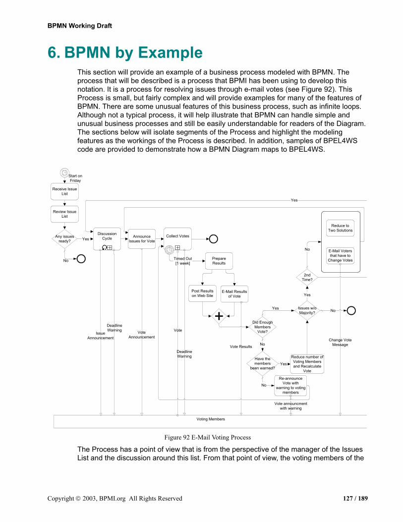
BPMN Working Draft
6. BPMN by ExampleThis section will provide an example of a business process modeled with BPMN. The process that will be described is a process that BPMI has been using to develop this notation. It is a process for resolving issues through e-mail votes (see Figure 92). This Process is small, but fairly complex and will provide examples for many of the features of BPMN. There are some unusual features of this business process, such as infinite loops. Although not a typical process, it will help illustrate that BPMN can handle simple and unusual business processes and still be easily understandable for readers of the Diagram. The sections below will isolate segments of the Process and highlight the modeling features as the workings of the Process is described. In addition, samples of BPEL4WS code are provided to demonstrate how a BPMN Diagram maps to BPEL4WS.
Figure 92 E-Mail Voting Process
The Process has a point of view that is from the perspective of the manager of the Issues List and the discussion around this list. From that point of view, the voting members of the
Yes
Yes
2ndTime?
Issues w/oMajority?
Did EnoughMembers
Vote?
Have themembers
been warned?
E-Mail Resultsof Vote
Reduce number ofVoting Membersand Recalculate
Vote
Re-announceVote with
warning to votingmembers
Timed Out[1 week]
Voting Members
Vote
Vote Results
Vote announcmentwith warning
VoteAnnouncement
Yes
Yes
Reduce toTwo Solutions
E-Mail Votersthat have to
Change VotesPrepareResults
AnnounceIssues for Vote
Any issuesready?
Review IssueList
Start onFriday
Post Resultson Web Site
Receive IssueList
DiscussionCycle Collect Votes
IssueAnnouncement
DeadlineWarning
DeadlineWarning
Change VoteMessage
No
Yes
No
No
No
No
Copyright 2003, BPMI.org All Rights Reserved 127 / 189

6.1 The Beginning of the Process BPMN Working Draft6.1.1 Mapping to BPEL4WS
working group are considered as external Participants who will be communicated with by messages (shown as Message Flow).
6.1 The Beginning of the ProcessThe Process starts with Timer Start Event that is set to trigger the Process every Friday (see Figure 93).
Figure 93 The Start of the Process
The Issue List Manager will review the list and determine if there are any issues that are ready for going through the discussion and voting cycle. Then a Decision must be made. If there are no issues ready, then the Process is over for that week--to be taken up again the following week. If there are issues ready, then the Process will continue with the discussion cycle. The “Discussion Cycle” Sub-Process is the first activity after the “Any issues ready?” Decision and this Sub-Process has two incoming Sequence Flows, one of which originates from a downstream Decision and is thus part of a loop. It is one of a set of five complex loops that exist in the Process. The contents of the “Discussion Cycle” Sub-Process and the activities that follow will be described below.
6.1.1 Mapping to BPEL4WSBPEL4WS processes must begin with a receive activity for instantiation (i.e., it “bootstraps” itself). The “E-Mail Voting Process” is scheduled to start every Friday as shown by the Timer Start Event. Therefore, an additional Process will have to be created and implemented that will run indefinitely and will send a starting message with the list of Issues to the “E-Mail Voting Process” every Friday. Figure 94 shows this Process as starting that the beginning of the Working Group and continuing until the end of the Working Group. Even this Process needs a message to be sent to it to signal the start of the Working Group. There may be another Process defined that sends that message, but that Process is not shown here. In addition, the mapping from the Starter Process to BPEL4WS is not shown here.
Yes
+
DiscussionCycle
Any issuesready?
Review IssueList
To Task:"Announce Issues
for Vote"
A Loop:From "Yes"
Alternative of the"2nd Time?"
DecisionUser Activity
CollapsedSub-Process
Receive IssueList
No
Issue List
Start onFriday
Issue Voting List[0 to 5 Issues]
128 / 189 Copyright 2003, BPMI.org All Rights Reserved

BPMN Working Draft 6. BPMN by Example6.1.1 Mapping to BPEL4WS
Figure 94 The Ongoing Starter Process
• Within the main Process (see Figure 93), the “Receive Issue List” Task will map to a BPEL4WS receive that has its createInstance attribute set to “yes.” This will receive starting message and start the process.
• This receive will be placed inside a sequence since other activities follow the activity. The message to be received will contain all the variable parts that will be used in the process and their initialized values.
Note: the names of BPD objects have all non-alphanumeric characters stripped from them when they are mapped to BPEL4WS name elements to match the BPEL4WS element restrictions.
The modeler-defined properties of the Process will be placed in a BPEL4WS variables element named “processData.” The same variables element will be used in all derived processes in this example.
• The “Review Issue List” Task will map to a BPEL4WS invoke. This TaskType is User, which means that the invoke will be synchronous and an outputVariable included.
Mapping an Exclusive Gateway (Decision)• The “Any Issues Ready?” Exclusive Gateway (Decision) will map to a BPEL4WS
switch.
• The Gate for the “No” Sequence Flow will map to the otherwise case of the switch. This otherwise will only contain an empty activity since there is nothing to do and the Process is over.
Note that empty does not have any corresponding activity in the BPMN Diagram, but is derived through the Diagram configuration.
• The Gate for the “Yes” Sequence Flow will map to other case for the switch. This case
Friday at 6PM Pacific
Time
Yes
WorkingGroup Still
Active?
No
Check Status ofWorking Group
[Send]Send Current
Issue List
WorkingGroupActive
Issue List
Copyright 2003, BPMI.org All Rights Reserved 129 / 189

6.1 The Beginning of the Process BPMN Working Draft6.1.1 Mapping to BPEL4WS
will have a condition that checks the number of issues that are ready. This case will handle the remainder of the Process that is shown in Figure 92.
This is done because the switch is a block structure and needs a definitive ending point and since the otherwise is connected to the end of the Process, then the end of the Process is the ending point that the case must use. The actual activities that make up the rest of the Process will be distributed among a set of BPEL4WS processes instead of all being within the case. The case will only contain an invoke that will call another process (as a web service). The distribution of the Process activities is due to the overall Diagram configuration that includes three upstream Sequence Flow that define some interleaving loops.
The Impact of Complex LoopsIf the loop shown in this section of the model were merely a simple loop, and perhaps the only loop, then a BPEL4WS while would be used to handle the loop. In this situation, though, the looping is handled through a set of derived processes that are accessed by invoking them (as a web service). There would no specific Diagram element to represent these derived processes; indeed, a modeler would not want to create a set of related Processes to handle complex looping. While an execution engine can easily handle a complex set of language documents and elements, a business person developing and monitoring this process will want to see the Process in an easy-to-read format (such as BPMN) that contains the information in a more comprehensive, less distributed format. In this example, all derived processes will be named “DerivedProcess<number>” and the number will be incremented as they are created. Any naming scheme will work as long as all the processes have unique names.
• Thus, to handle the rest of the Process, a derived nested process named “DerivedProcess1” is created and then
• A BPEL4WS invoke is used to access this process from the “Yes” case of the “Any issues ready?” switch.
We shall see that later in the Process the same process is accessed through another invoke, marking the source of the loop.
Note: All the derived processes in the BPEL4WS samples are accessed through an asynchronous invoke. That is, the invoke uses a one-way WSDL operation and the outputVariable element is not used in the invoke. Thus, the “calling” process will not wait until the “called” process completes. This type of invoking may also be called spawning.
All the sub-processes and derived processes in the BPEL4WS documents must be started with the receipt of a message.
• This means that a receive will be the first activity inside a sequence that will be the main activity of these processes. These receive activities will have the createInstance attribute set to “Yes.” A partnerLink named “internal,” a portType name “processPort” will be created to support all of these process to process communications. The WSDL operations that will support these communications will all be named “call<process name>” (as noted above, the processes are actually spawned).
130 / 189 Copyright 2003, BPMI.org All Rights Reserved

BPMN Working Draft 6. BPMN by Example6.1.1 Mapping to BPEL4WS
The “Discussion Cycle” Sub-Process shown in Figure 93 will continue the sequence (after the instantiating receive) for the “DerivedProcess1” process.
• Since “Discussion Cycle” is a Sub-Process it will map to a separate BPEL4WS process that is access through an invoke (in this case synchronously, since we don’t want to continue the Process until the Sub-Process has completed).
Mapping an Activity Loop ConditionThe “Discussion Cycle” Process has a loop marker. In this situation, the looping mechanism is simple. The attributes of the Sub-Process will tell us the details. The “Discussion Cycle” Sub-Process’s relevant attributes are: LoopType = “Standard”; LoopCondition = DiscussionOver = “FALSE”; TestTime = “After.”
• This means that the invoke that calls the process will be enclosed within a while activity when the BPEL4WS is derived.
• All variations of LoopType will map to a BPEL4WS while. The LoopCondition of the Process (as shown above) will map to the “DiscussionOver = False” will be the condition for the while.
The default value for the “DiscussionOver” property is False, thus an activity within the Sub-Process will have to change it to True before the while loop is over. The logical opposite of the expression that is shown in the Sub-Process attributes is used since the EvaluationCondition property is “after.” However, a while will test the condition prior to running the activity within. This means that to insure that the activity is always performed at least once (to mimic the behavior of an “until”) a LoopCounter variable will always be added to a the while condition for an BPMN activity that has its TestTime attribute set to “After.”
• The LoopCounter will be initialized to zero, and an assign will be automatically added as a part of variable.
• The activity of the while will be changed to a sequence, with the invoke for the Sub-Process, which is
• Followed by an assign that will increment the LoopCounter variable, inside the sequence.
We will look into the details of the “Discussion Cycle” Sub-Process in the section entitled “The First Sub-Process” on page 133.
Copyright 2003, BPMI.org All Rights Reserved 131 / 189
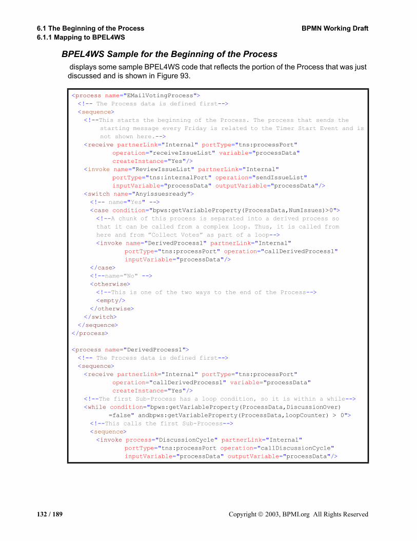
6.1 The Beginning of the Process BPMN Working Draft6.1.1 Mapping to BPEL4WS
BPEL4WS Sample for the Beginning of the Process displays some sample BPEL4WS code that reflects the portion of the Process that was just discussed and is shown in Figure 93.
<process name="EMailVotingProcess"><!-- The Process data is defined first--><sequence> <!--This starts the beginning of the Process. The process that sends the
starting message every Friday is related to the Timer Start Event and is not shown here.-->
<receive partnerLink="Internal" portType="tns:processPort" operation="receiveIssueList" variable="processData" createInstance="Yes"/>
<invoke name="ReviewIssueList" partnerLink="Internal" portType="tns:internalPort" operation="sendIssueList" inputVariable="processData" outputVariable="processData"/>
<switch name="Anyissuesready"><!-- name="Yes" --><case condition="bpws:getVariableProperty(ProcessData,NumIssues)>0"><!--A chunk of this process is separated into a derived process so that it can be called from a complex loop. Thus, it is called from here and from ”Collect Votes” as part of a loop--><invoke name="DerivedProcess1" partnerLink="Internal"
portType="tns:processPort" operation="callDerivedProcess1" inputVariable="processData"/>
</case><!--name="No" --><otherwise><!--This is one of the two ways to the end of the Process--> <empty/>
</otherwise></switch>
</sequence></process>
<process name="DerivedProcess1"><!-- The Process data is defined first--><sequence><receive partnerLink="Internal" portType="tns:processPort"
operation="callDerivedProcess1" variable="processData" createInstance="Yes"/>
<!--The first Sub-Process has a loop condition, so it is within a while--><while condition="bpws:getVariableProperty(ProcessData,DiscussionOver)
=false" andbpws:getVariableProperty(ProcessData,loopCounter) > 0"><!--This calls the first Sub-Process--><sequence> <invoke process="DiscussionCycle" partnerLink="Internal"
portType="tns:processPort operation="callDiscussionCycle" inputVariable="processData" outputVariable="processData"/>
132 / 189 Copyright 2003, BPMI.org All Rights Reserved
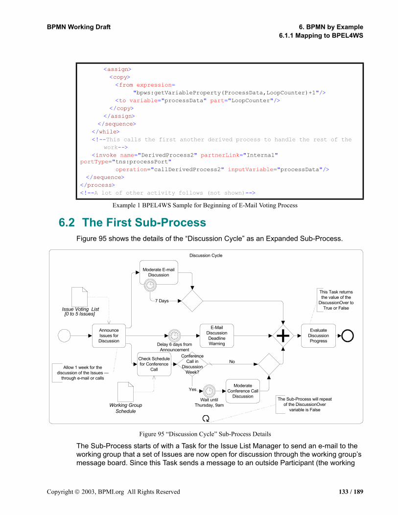
BPMN Working Draft 6. BPMN by Example6.1.1 Mapping to BPEL4WS
Example 1 BPEL4WS Sample for Beginning of E-Mail Voting Process
6.2 The First Sub-ProcessFigure 95 shows the details of the “Discussion Cycle” as an Expanded Sub-Process.
Figure 95 “Discussion Cycle” Sub-Process Details
The Sub-Process starts of with a Task for the Issue List Manager to send an e-mail to the working group that a set of Issues are now open for discussion through the working group’s message board. Since this Task sends a message to an outside Participant (the working
<assign><copy><from expression=
"bpws:getVariableProperty(ProcessData,LoopCounter)+1"/><to variable="processData" part="LoopCounter"/>
</copy></assign>
</sequence></while><!--This calls the first another derived process to handle the rest of the
work--><invoke name="DerivedProcess2" partnerLink="Internal"
portType="tns:processPort"operation="callDerivedProcess2" inputVariable="processData"/>
</sequence></process><!--A lot of other activity follows (not shown)-->
7 Days
Yes
E-MailDiscussionDeadlineWarningDelay 6 days from
Announcement
AnnounceIssues forDiscussion
ModerateConference Call
Discussion
ConferenceCall in
DiscussionWeek?
Wait untilThursday, 9am
Check Schedulefor Conference
Call
EvaluateDiscussionProgress
Moderate E-mailDiscussion
Discussion Cycle
Allow 1 week for thediscussion of the Issues —
through e-mail or calls
This Task returnsthe value of the
DiscussionOver toTrue or False
The Sub-Process will repeatof the DiscussionOver
variable is False
No
Issue Voting List[0 to 5 Issues]
Working GroupSchedule
Copyright 2003, BPMI.org All Rights Reserved 133 / 189

6.2 The First Sub-Process BPMN Working Draft6.1.1 Mapping to BPEL4WS
group members), an outgoing Message Flow is seen from the “Discussion Cycle” Sub-Process to the “Voting Members” Pool in Figure 92. Basically, the working group will be discussing the issues for one week and proposing additional solutions to the issues. After the first Task, three separate parallel paths are followed, which are synchronized downstream. This is shown by the three outgoing Sequence Flow for that activity.
The top parallel path in the figure starts with a long-running Task, “Moderate E-mail Discussion,” that has a Timer Intermediate Event attached to its boundary. Although the “Moderate E-Mail Discussion” Task will never actually be completed normally in this model, there must be an outgoing Sequence Flow for the Task since Start and End Events are being used within the Process. This Sequence Flow will merged with the Sequence Flow that comes from the Timer Intermediate Event. A merging Exclusive Gateway is used in this situation because the next object is a joining Parallel Gateway (the diamond with the cross in the center) that is used to synchronize the three parallel paths. If the merging Gateway was not used and both Sequence Flow connected to the joining Gateway, the Process would have been stuck at the joining Gateway that would wait for a Token to arrive from each of the incoming Sequence Flow.
The middle parallel path of the fork contains an Intermediate Event and a Task. A Timer Intermediate Event used in the middle of the Process flow (not attached to the boundary of an activity) will cause a delay. This delay is set to 6 days. The “E-Mail Discussion Deadline Warning” Task will follow. Again, since this Task sends a message to an outside Participant, an outgoing Message Flow is seen from the “Discussion Cycle” Sub-Process to the “Voting Members” Pool in Figure 92.
The bottom parallel path of the fork contains more than one object, first of which is Task where the issue list manager checks the calendar to see if there is a conference call this week. The output of the Task will be an update to the variable “ConCall,” which will be true or false. After the Task, an Exclusive Gateway with its two Gates follows. The Gate for labeled “default” flows directly to an merging Exclusive Gateway, for the same reason as in the top parallel path. The Gate for the “Yes” Sequence Flow will have a condition that checks the value of the “ConCall” variable (set in the previous Task) to see if there will be a conference call during the coming week. If so, the Timer Intermediate Event indicates delay, since all conference calls for the working group start at 9am PDT on Thursdays. The Task for moderating the conference call follows the delay, which is followed the merging Gateway.
The merging Gateways in the top and bottom paths and the “E-Mail Discussion Deadline Warning” Task all flow into a joining Gateway. This Gateway waits for all three paths to complete before the Process flows to the next Task, “Evaluate Discussion Progress.” The issue list manager will review the status of the issues and the discussions during the past week and decide if the discussions are over. The DiscussionOver variable will be set to TRUE or FALSE, depending on this evaluation. If the variable is set to FALSE, then the whole Sub-Process will be repeated, since it has looping set and the loop condition will test the DiscussionOver variable.
134 / 189 Copyright 2003, BPMI.org All Rights Reserved

BPMN Working Draft 6. BPMN by Example6.2.1 Mapping to BPEL4WS
6.2.1 Mapping to BPEL4WS• The “Discussion Cycle” Sub-Process itself maps to a BPEL4WS process.
Because it is a Sub-Process within a higher-level Process (the “E-Mail Voting” Process), it is invoked from the higher-level Process. The invoke sends a message from one (higher-level) BPEL4WS process to the other (lower-level) process for instantiation.
• This means that the process being instantiated must have a receive to start it off.
The receive is not actually shown in the BPMN Diagram, but it is derived from this invoke-receive relationship of “Discussion Cycle” Process being a Sub-Process to the “E-Mail Voting” Process.
• Given this, the activity of the BPEL4WS process will be a sequence with the derived receive as the first activity.
The Diagrams elements of Figure 95 will determine the remaining activity(ies) of the sequence.
• The Sub-Process starts off with a Task, which maps to a BPEL4WS invoke (which is after the automatically generated receive that starts the process).
• After the first Task, three separate parallel paths are followed. The forking of the flow marks the start of a BPEL4WS flow. The flow will extend until the Parallel Gateway, which joins the three paths.
The Upper Parallel PathIn the upper parallel path of the fork, the Task, “Moderate E-mail Discussion,” has a Timer Intermediate Event attached to its boundary. Because of this,
• the Task is placed in its own scope with a faultHandler.
• The Task itself is mapped to a BPEL4WS invoke (synchronous), and will be placed in a lower-level flow, for reasons described below.
The lower-level flow will be listed in the higher-level flow without a source sub-element. This means that the lower-level flow will be instantiated when the higher-level flow begins since it has no dependencies on any other activity. The Timer Intermediate Event must be set up to create a fault at the appropriate time. To do this,
• a lower-level flow is created that contains the above invoke plus a sequence that contains a wait.
• The wait is set to the duration that is defined in the Timer Intermediate Event.
• After the wait, a throw creates a fault name after the Intermediate Event with “_fault” appended.
The catch of the faultHandler will be triggered by the fault generated by the above throw. Since the Timer Intermediate Event leads direction to the Exclusive Gateway, there is no specific activity that must be performed in response the to time-out. The main purpose is to exit the Task. Thus,
• the catch will contain an empty activity.
Copyright 2003, BPMI.org All Rights Reserved 135 / 189
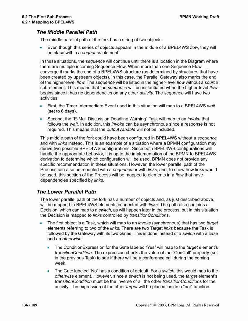
6.2 The First Sub-Process BPMN Working Draft6.2.1 Mapping to BPEL4WS
The Middle Parallel PathThe middle parallel path of the fork has a string of two objects.
• Even though this series of objects appears in the middle of a BPEL4WS flow, they will be place within a sequence element.
In these situations, the sequence will continue until there is a location in the Diagram where there are multiple incoming Sequence Flow. When more than one Sequence Flow converge it marks the end of a BPEL4WS structure (as determined by structures that have been created by upstream objects). In this case, the Parallel Gateway also marks the end of the higher-level flow. The sequence will be listed in the higher-level flow without a source sub-element. This means that the sequence will be instantiated when the higher-level flow begins since it has no dependencies on any other activity. The sequence will have two activities:
• First, the Timer Intermediate Event used in this situation will map to a BPEL4WS wait (set to 6 days).
• Second, the “E-Mail Discussion Deadline Warning” Task will map to an invoke that follows the wait. In addition, this invoke can be asynchronous since a response is not required. This means that the outputVariable will not be included.
This middle path of the fork could have been configured in BPEL4WS without a sequence and with links instead. This is an example of a situation where a BPMN configuration may derive two possible BPEL4WS configurations. Since both BPEL4WS configurations will handle the appropriate behavior, it is up to the implementation of the BPMN to BPEL4WS derivation to determine which configuration will be used. BPMN does not provide any specific recommendation in these situations. However, the lower parallel path of the Process can also be modeled with a sequence or with links, and, to show how links would be used, this section of the Process will be mapped to elements in a flow that have dependencies specified by links.
The Lower Parallel PathThe lower parallel path of the fork has a number of objects and, as just described above, will be mapped to BPEL4WS elements connected with links. The path also contains a Decision, which can map to a switch, as will happen later in the process, but in this situation the Decision is mapped to links controlled by transitionConditions.
• The first object is a Task, which will map to an invoke (synchronous) that has two target elements referring to two of the links. There are two Target links because the Task is followed by the Gateway with its two Gates. This is done instead of a switch with a case and an otherwise.
• The ConditionExpression for the Gate labeled “Yes” will map to the target element’s transitionCondition. The expression checks the value of the “ConCall” property (set in the previous Task) to see if there will be a conference call during the coming week.
• The Gate labeled “No” has a condition of default. For a switch, this would map to the otherwise element. However, since a switch is not being used, the target element’s transitionCondition must be the inverse of all the other transitionConditions for the activity. The expression of the other target will be placed inside a “not” function.
136 / 189 Copyright 2003, BPMI.org All Rights Reserved

BPMN Working Draft 6. BPMN by Example6.2.1 Mapping to BPEL4WS
The invoke will be listed in the higher-level flow without a source sub-element. This means that the invoke will be instantiated when the higher-level flow begins since it has no dependencies on any other activity. The remaining elements of the higher-level flow will have a source element. Thus, they will not be instantiated until the source of the link has completed.
• The “Yes” Gate from the Gateway leads to a Timer Intermediate Event, which will map to a wait.
• The for element of the wait will set to for 9am PDT on the next Thursday.
• This wait will have a source element that corresponds to the target element from the previous invoke.
• The wait will also have a target element to link to the following invoke.
• The “No” Gate from the Gateway leads to a merging Exclusive Gateway, which means that nothing is expected to happen down this path. Thus, this will map to an empty.
• This empty will have a source element that corresponds to the target element from the previous invoke.
• The Task for moderating the conference call follows the wait, which will map to an invoke (synchronous).
• This invoke will have a source element that corresponds to the target element from the previous wait.
There are three link elements in the flow:
• One link will have a source of the first invoke and a target of the wait.
• One link will have a source of the first invoke and a target of the empty.
• One link will have a source of the first wait and a target of the last invoke.
As mentioned above, the Parallel Gateway marks the end of the flow.
After the Parallel Paths are JoinedThe Task “Evaluate Discussion Progress” is intended to occur only when all the parallel paths have completed, and thus, it will
• Map to an invoke that follows the closing of the flow.
Copyright 2003, BPMI.org All Rights Reserved 137 / 189
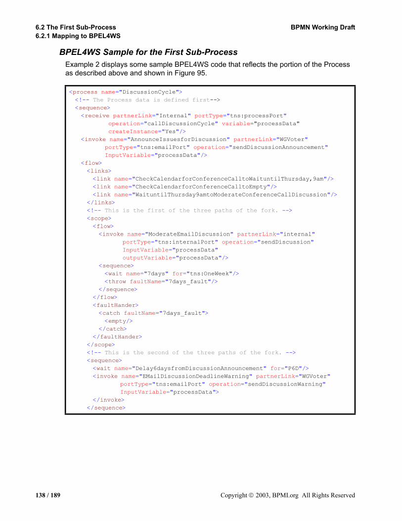
6.2 The First Sub-Process BPMN Working Draft6.2.1 Mapping to BPEL4WS
BPEL4WS Sample for the First Sub-ProcessExample 2 displays some sample BPEL4WS code that reflects the portion of the Process as described above and shown in Figure 95.
<process name="DiscussionCycle"><!-- The Process data is defined first--><sequence><receive partnerLink="Internal" portType="tns:processPort"
operation="callDiscussionCycle" variable="processData" createInstance="Yes"/>
<invoke name="AnnounceIssuesforDiscussion" partnerLink="WGVoter" portType="tns:emailPort" operation="sendDiscussionAnnouncement" InputVariable="processData"/>
<flow><links><link name="CheckCalendarforConferenceCalltoWaituntilThursday,9am"/><link name="CheckCalendarforConferenceCalltoEmpty"/><link name="WaituntilThursday9amtoModerateConferenceCallDiscussion"/>
</links><!-- This is the first of the three paths of the fork. --><scope><flow><invoke name="ModerateEmailDiscussion" partnerLink="internal"
portType="tns:internalPort" operation="sendDiscussion" InputVariable="processData" outputVariable="processData"/>
<sequence><wait name="7days" for="tns:OneWeek"/><throw faultName="7days_fault"/>
</sequence></flow><faultHander><catch faultName="7days_fault"><empty/>
</catch></faultHander>
</scope><!-- This is the second of the three paths of the fork. --><sequence><wait name="Delay6daysfromDiscussionAnnouncement" for="P6D"/><invoke name="EMailDiscussionDeadlineWarning" partnerLink="WGVoter"
portType="tns:emailPort" operation="sendDiscussionWarning" InputVariable="processData">
</invoke></sequence>
138 / 189 Copyright 2003, BPMI.org All Rights Reserved

BPMN Working Draft 6. BPMN by Example6.2.1 Mapping to BPEL4WS
Example 2 BPEL4WS Sample of “Discussion Cycle” Sub-Process Details
6.3 The Second Sub-ProcessFigure 96 shows the next section of the Process, which includes the expanded details of the “Collect Votes” Sub-Process.
<!-- This is the third of the three paths of the fork. --><invoke name="CheckCalendarforConferenceCall" partnerLink="internal"
portType="tns:internalPort" operation="receiveCallSchedule" InputVariable="processData" outputVariable="processData">
<target linkName="CheckCalendarforConferenceCalltoWaituntilThursday9am" transitionCondition="bpws:getVariableProperty(processData,conCall)
=true"/><target linkName="CheckCalendarforConferenceCalltoEmpty"
transitionCondition="not(bpws:getVariableProperty(processData,conCall)=true)"/>
</invoke><!-- name="Yes" --><wait name="WaituntilThursday9am" for="P6DT9H"><source linkName="CheckCalendarforConferenceCalltoWaituntilThursday9am"><target linkName="WaituntilThursday9amtoModerateConferenceCall
Discussion"/></wait><invoke name="ModerateConferenceCallDiscussion" partnerLink="internal"
portType="tns:internalPort" operation="sendConCall" InputVariable="processData" outputVariable="processData">
<source linkName="WaituntilThursday9amtoModerateConferenceCall Discussion"/>
</invoke><!-- name="otherwise" --><empty><source linkName="CheckCalendarforConferenceCalltoEmpty"/>
</empty></flow><invoke name="EvaluateDiscussionProgress" partnerLink="internal"
portType="tns:internalPort" operation="receiveDiscussionStatus" InputVariable="processData" outputVariable="processData"/>
</sequence></process>
Copyright 2003, BPMI.org All Rights Reserved 139 / 189
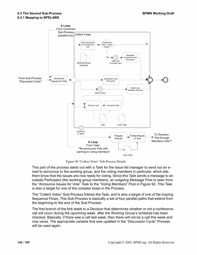
6.3 The Second Sub-Process BPMN Working Draft6.2.1 Mapping to BPEL4WS
Figure 96 “Collect Votes” Sub-Process Details
This part of the process starts out with a Task for the issue list manager to send out an e-mail to announce to the working group, and the voting members in particular, which lets them know that the issues are now ready for voting. Since this Task sends a message to an outside Participant (the working group members), an outgoing Message Flow is seen from the “Announce Issues for Vote” Task to the “Voting Members” Pool in Figure 92. This Task is also a target for one of the complex loops in the Process.
The “Collect Votes” Sub-Process follows the Task, and is also a target of one of the looping Sequence Flows. This Sub-Process is basically a set of four parallel paths that extend from the beginning to the end of the Sub-Process.
The first branch of the fork leads to a Decision that determines whether or not a conference call will occur during the upcoming week, after the Working Group’s schedule has been checked. Basically, if there was a call last week, then there will not be a call this week and vice versa. The appropriate variable that was updated in the “Discussion Cycle” Process will be used again.
AnnounceIssues for Vote
Yes
PrepareResults
E-Mail Resultsof Vote
Moderate E-mailDiscussion
Increment TallyReceive Vote
ConferenceCall in Voting
Week?
ModerateConference Call
Discussion
E-Mail VoteDeadline Warning
Delay 6 Days
A Loop:From Unnamed
Sub-Process(parallel box)
A Loop:From Task:
"Re-announce Vote withwarning to voting members"
To Decision:"Did Enough
Members Vote?"
From Sub-Process:"Discussion Cycle"
Collect Votes
Timed Out[1 week]
Issue Votes
Wait untilThursday, 9am
No
Vote Vote Tally
Check Schedulefor Conference
Call
Working GroupSchedule
140 / 189 Copyright 2003, BPMI.org All Rights Reserved
BPMN Working Draft 6. BPMN by Example6.3.1 Mapping to BPEL4WS
The second and third branches forks work the same way as the similar activities in the “Discussion Cycle” Sub-Process, except that the “Moderate E-Mail Discussion” Task does not have a Timer Intermediate Event attached. This is not necessary since the whole Sub-Process is interrupted after 7 days through the Intermediate Event attached to the Sub-Process boundary. The “E-Mail Vote Deadline Warning” Task sends a message to an outside Participant (the working group members), thus, an outgoing Message Flow is seen from the “Collect Votes” Sub-Process to the “Voting Members” Pool in Figure 92.
The fourth branch of the fork is rather unique in that the Diagram uses a loop that does not utilize a Decision. Thus, it is, as it is intended to be, an infinite loop. The policy of the working group is that voting members can vote more than once on an issue; that is, they can change their mind as many times as they want throughout the entire week. The first Task in the loop receives a message from the outside Participant (the working group members), thus, an incoming Message Flow is seen from the “Voting Members” Pool to the “Collect Votes” Sub-Process in Figure 92. The Timer Intermediate Event attached to the boundary of the Sub-Process is the mechanism that will end the infinite loop, since all work inside the Sub-Process will be ended when the time-out is triggered. All the remaining work of the Process is conducted after the time-out and flows from the Timer Intermediate Event.
Figure 96 shows that there are Two Tasks that follow the time-out. First, a Task will prepare all the voting results, then a Task will send the results to the voting members. A Document Object, “Issue Votes,” is shown in the Diagram to illustrate how one might be used, but it will not map to anything in the execution languages. The remaining activities of the Process will be described in the next section.
6.3.1 Mapping to BPEL4WS
The Loops Cause Derived Sub-Processes• The first Task of this section of the Process is also a target for one of the complex loops
in the Process, thus, it will map to an invoke (asynchronous) that is placed inside another derived process (“DerivedProcess2”).
• This derived process will be invoked from “DerivedProcess1,” after the “Discussion Cycle” process has been completed, as part of the normal flow and then from another part of the Process as part of the looping flow.
• Thus, “DerivedProcess2” will require a (instantiation) receive to accept the message from “DerivedProcess1” and from “DerivedProcess4” (as we shall see later).
• The “Collect Votes” Sub-Process follows the Task, but is also a target of one of the looping Sequence Flows. Thus, it will also be set inside a derived process (“DerivedProcess3”).
• In addition, “DerivedProcess3” will require a (instantiation) receive to accept the message from “DerivedProcess2” and from the fault handler of “Collect Votes” (as we shall see later).
• The “Collect Votes” Sub-Process will map to an invoke (asynchronous) and the details will be in a process referenced through the invoke.
Copyright 2003, BPMI.org All Rights Reserved 141 / 189

6.3 The Second Sub-Process BPMN Working Draft6.3.1 Mapping to BPEL4WS
The BPEL4WS Sample of the Derived Sub-ProcessesExample 3 shows sample BPEL4WS code that defines the two derived processes.
Example 3 BPEL4WS Sample that sets up the Access for the Second Sub-Process
The Paths of the Sub-ProcessThe “Collect Votes Sub-Process is basically a set of four parallel paths that extend from the beginning to the end of the Sub-Process.
• Thus, the activity for the process will be a flow.
The Upper Parallel PathThe first branch of this Sub-Process is basically the same as the upper parallel of the previous Sub-Process. An invoke, a wait, and an empty will be created. In addition, three links will be created to handle the dependencies between the elements, including the branching created by the Exclusive Gateway. Refer to the section entitled “The Lower Parallel Path” on page 136 for the details of the mappings.
<process name="DerivedProcess2"><!-- This starts the middle section of the Process and is call from
the first time and then from “Collect Votes” during a loop--><!-- The Process data is defined first--><sequence><receive partnerLink="Internal" portType="tns:processPort"
operation="callDerivedProcess2" variable="processData" createInstance="Yes"/>
<invoke name="AnnounceIssuesforVote" partnerLink="WGVoter" portType="tns:emailPort" operation="sendVoteAnnouncement" InputVariable="processData"/>
<invoke name="DerivedProcess3" partnerLink="Internal" portType="tns:processPort" operation="callDerivedProcess3" InputVariable="processData"/>
</sequence></process>
<process name="DerivedProcess3"><!-- this calls the second Sub-Process and then continues. It is also
called from “Collect Votes” as part of a loop--><!-- The Process data is defined first--><sequence><receive partnerLink="Internal" portType="tns:processPort"
operation="callDerivedProcess3" variable="processData" createInstance="Yes"/>
<invoke name="CollectVotes" partnerLink="Internal" portType="tns:processPort" operation="callCollectVotes" InputVariable="processData"/>
</sequence></process>
142 / 189 Copyright 2003, BPMI.org All Rights Reserved

BPMN Working Draft 6. BPMN by Example6.3.1 Mapping to BPEL4WS
The Middle Two Parallel PathsThe second and third branches of the fork are rather straightforward mappings of:
• Two Tasks to invokes (one synchronous and one asynchronous), and
• A Timer Intermediate Event to a delay.
• In addition, one link is created so that one of the invokes will wait for the delay.
The Lower Parallel PathThe fourth branch of the fork is the location the infinite loop.
• This loop will map to a BPEL4WS while with a condition of “1!=0,” which will always be false.
• Inside the while is a sequence of two invokes (one synchronous and one asynchronous), which are mapped from the two Tasks in the loop.
Exiting the Second Sub-ProcessTo exit out of the infinite loop and the whole “Collect Votes” Sub-Process,
• a scope will be wrapped around the main flow of the process, which will include a faultHandler.
The Timer Intermediate Event must be set up to create a fault at the appropriate time. To do this,
• A higher-level flow is created that contains the activities of the Sub-Process with the addition of a sequence.
• The sequence contains a wait. The wait is set to the duration that is defined in the Timer Intermediate Event.
• After the wait, a throw creates a fault name after the Intermediate Event with “Fault” appended.
The catch element of the faultHandler will be triggered by the fault generated by the above throw.
• The activity for the catch will be a sequence and will be the source of all the remaining activities of the Process, since all the remaining Sequence Flow begins from the Timer Intermediate Event.
• The first two Tasks, as shown in the figure, will map to invokes (one synchronous and the other asynchronous).
The Document Object shown in the figure is not mapped into BPEL4WS. The remainder of the Process will be described in the next section.
Copyright 2003, BPMI.org All Rights Reserved 143 / 189

6.3 The Second Sub-Process BPMN Working Draft6.3.1 Mapping to BPEL4WS
BPEL4WS Sample for the Second Sub-ProcessExample 4 shows sample BPEL4WS code that defines the “Collect Votes” Sub-Process.
<process name="CollectVotes"><!--This is a nested process for the E-Mail Voting collection. It consists of
an all and a faultHandler (for a timeout). The all will never complete normally since there is an infinite loop inside. The timeout is intended to be the normal way of ending the process-->
<sequence><receive partnerLink="Internal" portType="tns:processPort"
operation="callCollectVotes" variable="processData" createInstance="Yes"/>
<scope><flow><sequence><wait name="7days" for="P7D"/><throw faultName="7daysFault"/>
</sequence><flow><links><link name="Delay6daysfromVoteAnnouncementtoEMailVote
DeadlineWarning"/><link name="CheckCalendarforConferenceCalltoWaituntilThursday9am"/><link name="CheckCalendarforConferenceCalltoEmpty"/><link name="WaituntilThursday9amtoModerateConferenceCallDiscussion"/>
</links><!--This is the first of the four paths of the fork. --><invoke name="CheckCalendarforConferenceCall" partnerLink="internal"
portType="tns:internalPort" operation="receiveCallSchedule" InputVariable="processData" outputVariable="processData">
<target linkName="CheckCalendarforConferenceCalltoWaituntilThursday9am"
transitionCondition="bpws:getVariableProperty(processData,conCall)=true"/>
<target linkName="CheckCalendarforConferenceCalltoEmpty"transitionCondition="not(bpws:getVariableProperty(processData,
conCall)=true)"/></invoke><!-- name="Yes" --><wait name="WaituntilThursday9am" for="P6DT9H"><source linkName=
"CheckCalendarforConferenceCalltoWaituntilThursday9am"><target linkName="WaituntilThursday9amtoModerateConferenceCall
Discussion"/></wait><invoke name="ModerateConferenceCallDiscussion" partnerLink="internal"
portType="tns:internalPort" operation="sendConCall" InputVariable="processData" outputVariable="processData">
<source linkName="WaituntilThursday9amtoModerateConferenceCall Discussion"/>
</invoke><!-- name="otherwise" -->
144 / 189 Copyright 2003, BPMI.org All Rights Reserved
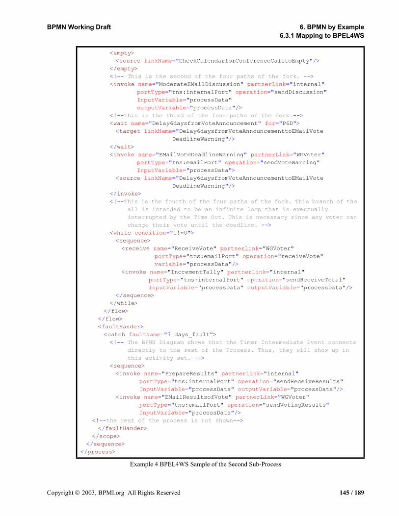
BPMN Working Draft 6. BPMN by Example6.3.1 Mapping to BPEL4WS
Example 4 BPEL4WS Sample of the Second Sub-Process
<empty><source linkName="CheckCalendarforConferenceCalltoEmpty"/>
</empty><!-- This is the second of the four paths of the fork. --><invoke name="ModerateEMailDiscussion" partnerLink="internal"
portType="tns:internalPort" operation="sendDiscussion" InputVariable="processData" outputVariable="processData"/>
<!--This is the third of the four paths of the fork.--><wait name="Delay6daysfromVoteAnnouncement" for="P6D"><target linkName="Delay6daysfromVoteAnnouncementtoEMailVote
DeadlineWarning"/></wait><invoke name="EMailVoteDeadlineWarning" partnerLink="WGVoter"
portType="tns:emailPort" operation="sendVoteWarning" InputVariable="processData">
<source linkName="Delay6daysfromVoteAnnouncementtoEMailVote DeadlineWarning"/>
</invoke><!--This is the fourth of the four paths of the fork. This branch of the
all is intended to be an infinite loop that is eventually interrupted by the Time Out. This is necessary since any voter can change their vote until the deadline. -->
<while condition="1!=0"><sequence><receive name="ReceiveVote" partnerLink="WGVoter"
portType="tns:emailPort" operation="receiveVote" variable="processData"/>
<invoke name="IncrementTally" partnerLink="internal" portType="tns:internalPort" operation="sendReceiveTotal" InputVariable="processData" outputVariable="processData"/>
</sequence></while>
</flow></flow><faultHander><catch faultName="7 days_fault"><!-- The BPMN Diagram shows that the Timer Intermediate Event connects
directly to the rest of the Process. Thus, they will show up in this activity set. -->
<sequence><invoke name="PrepareResults" partnerLink="internal"
portType="tns:internalPort" operation="sendReceiveResults" InputVariable="processData" outputVariable="processData"/>
<invoke name="EMailResultsofVote" partnerLink="WGVoter" portType="tns:emailPort" operation="sendVotingResults" InputVariable="processData"/>
<!--the rest of the process is not shown--></faultHander>
</scope></sequence>
</process>
Copyright 2003, BPMI.org All Rights Reserved 145 / 189
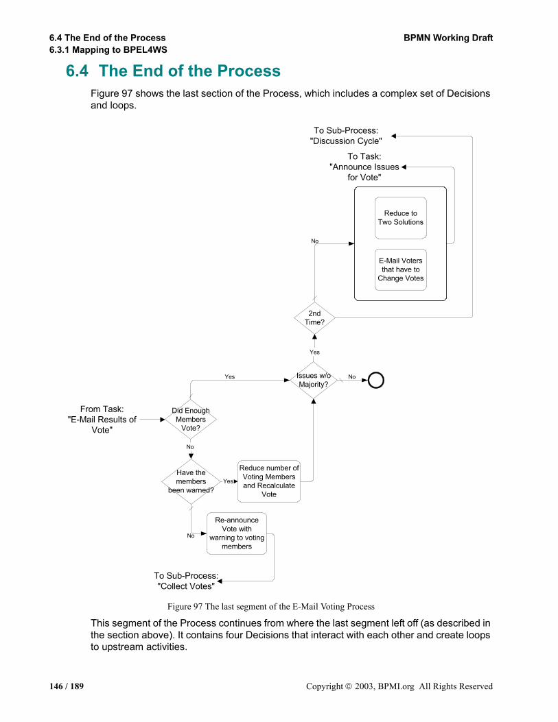
6.4 The End of the Process BPMN Working Draft6.3.1 Mapping to BPEL4WS
6.4 The End of the ProcessFigure 97 shows the last section of the Process, which includes a complex set of Decisions and loops.
Figure 97 The last segment of the E-Mail Voting Process
This segment of the Process continues from where the last segment left off (as described in the section above). It contains four Decisions that interact with each other and create loops to upstream activities.
Yes
No
Yes
2ndTime?
Issues w/oMajority?
Reduce toTwo Solutions
E-Mail Votersthat have to
Change Votes
Did EnoughMembers
Vote?
Have themembers
been warned?
Reduce number ofVoting Membersand Recalculate
Vote
Re-announceVote with
warning to votingmembers
From Task:"E-Mail Results of
Vote"
To Sub-Process:"Collect Votes"
To Sub-Process:"Discussion Cycle"
To Task:"Announce Issues
for Vote"
No
Yes No
No
146 / 189 Copyright 2003, BPMI.org All Rights Reserved

BPMN Working Draft 6. BPMN by Example6.4.1 Mapping to BPEL4WS
The first Decision, “Did Enough Members Vote?,” is necessary since two-thirds of the voting members are required to approve any solution to an issue. If less than two-thirds of the voting members cast votes, which sometimes happens, the issues can’t be resolved. This Decision flows to another Decision for both of its Alternatives. The “No” Alternative is followed by the “Have the Members been Warned?” Decision. If a voting member misses a vote, they are warned. If they miss a second vote, they lose their status as a voting member and the voting percentages are recalculate through a Task (“Reduce number of Voting Members and Recalculate Vote”). If they haven’t yet been warned, then a warning is sent and the voting week is repeated.
If all issues are resolved, then the Process is done. If not, then another Decision is required. The voting is given two chances before it goes back to another cycle of discussion. The first time will see a reduction of the number of solutions to the two most popular based on the vote (more if there are ties). Some voting members will have to change their votes just because their solution is no longer valid. These two activities are placed in a Sub-Process to show how a Sub-Process without Start and End Events can be used to create a simple set of parallel activities. Informally, this is called a “parallel box.” It is not a special object, but another use of Sub-Processes. For simple situations, it can be used to show a set of parallel activities without the extra clutter of a lot of Sequence Flows. In actuality, these two Tasks cannot actually be done in parallel, but they are modeled this way to highlight the optional use of Start and End Events.
After the parallel box, the flow loops back to the “Collect Votes” Sub-Process. If there already has been two cycles of voting, then the process flows back to the “Decision Cycle” Sub-Process.
6.4.1 Mapping to BPEL4WSAs mentioned above, the entire contents of this segment follow a Timer Intermediate Event, which means they are contained in the faultHandler of the scope within the “Collect Votes” process.
• Each of the Decisions in this section will map to a BPEL4WS switch.
The First DecisionThe first Decision, “Did Enough Members Vote?,” flows to another Decision for both of its Alternatives.
• Thus, each of the switch cases will contain another switch.
The “No” Alternative is followed by the “Have the Members been Warned?” Decision.
• Each Alternative from this Decision is followed by a Task, which maps to Invokes (one synchronous and the other asynchronous).
The “No (default)” Alternative leads to a loop.
• This looping is handled by using an invoke (asynchronous) to the “DerivedProcess3” process, which was created just for the purpose of this loop (since it is in the context of a more complex looping situation).
Notice that the “Issues w/o Majority?” Decision can be reached through the alternative paths from two different Decisions. This creates a situation that has two impacts on the Mapping to Execution Languages. First, it creates a section of the Process in which the
Copyright 2003, BPMI.org All Rights Reserved 147 / 189
6.4 The End of the Process BPMN Working Draft6.4.1 Mapping to BPEL4WS
Alternatives from two Decisions overlap. This is possible in a graph-structured Diagram like BPMN, but in a block-structured (and acyclic) language like BPEL4WS, these two sections cannot overlap because they have different block boundaries. This means that this section must be repeated in some way in both of the appropriate switch case activities. All these elements could be actually duplicated or they can be separated into a derived process and then invoked from the appropriate place. The later method was used in this example (see Example 5 and Example 6).
Note: At this point, BPMN does not specify whether a reused section of a BPMN Diagram should map to a derived process that is invoked from each location of duplication, or whether the section should remain intact and be duplicated in each appropriate location. This is left up to the specific implementation of BPMN since both solutions will behave equivalently.
The second impact of the multiple incoming Sequence Flows into the “Issues w/o Majority?” Decision has to do with how the three visible loops are created (actually there are five loops). Normally, Sequence Flow loops will map to a BPEL4WS while. If there are multiple loops in the Process they have to be physically separated or completely nested because of the block-structured nature of the BPEL4WS looping elements. The alternative paths of the Decisions cannot be mixed and still maintain the BPEL4WS blocks they way that the end of the “E-mail Voting” Process mixes the paths.
A different type of looping mechanism is required. This method requires the creation of a set of derived processes that can reference each other and also themselves. In this way, a block-structured language can simulate a set of interleaving loops (as seen in a graph-structured Diagram).
• Thus, in this BPMN example, derived processes were created to mark places where loops can be targeted within the BPEL4WS code from the “downstream” elements.
• A BPEL4WS invoke (asynchronous) is used to re-perform activities that had already been executed in the process.
Note: A synchronous invoke could also be used to access the processes to perform the loop. With a synchronous invoke, the source process would remain active until the target process (and any other loops that follow) have been completed before it also completes. With an asynchronous invoke, the source process would complete immediately, reducing the number of active BPM system resources. At this point, BPMN does not specify whether an asynchronous invoke or a synchronous invoke should be used in this situation.
148 / 189 Copyright 2003, BPMI.org All Rights Reserved
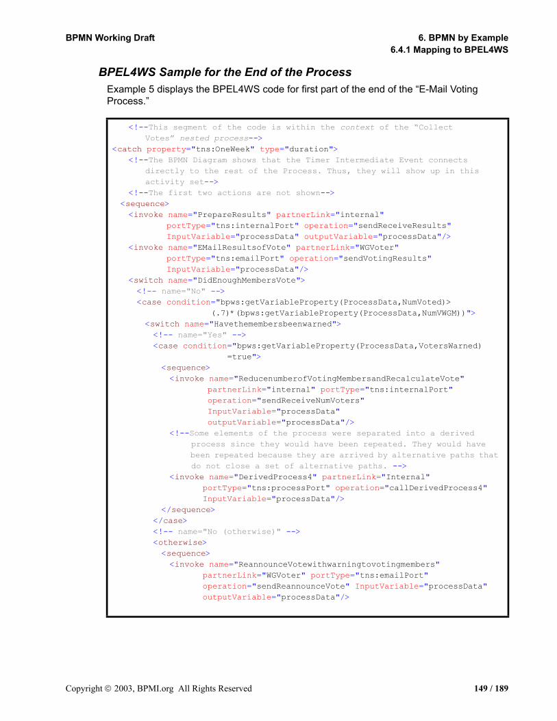
BPMN Working Draft 6. BPMN by Example6.4.1 Mapping to BPEL4WS
BPEL4WS Sample for the End of the ProcessExample 5 displays the BPEL4WS code for first part of the end of the “E-Mail Voting Process.”
<!--This segment of the code is within the context of the “Collect Votes” nested process-->
<catch property="tns:OneWeek" type="duration"><!--The BPMN Diagram shows that the Timer Intermediate Event connects
directly to the rest of the Process. Thus, they will show up in this activity set-->
<!--The first two actions are not shown--><sequence><invoke name="PrepareResults" partnerLink="internal"
portType="tns:internalPort" operation="sendReceiveResults" InputVariable="processData" outputVariable="processData"/>
<invoke name="EMailResultsofVote" partnerLink="WGVoter" portType="tns:emailPort" operation="sendVotingResults" InputVariable="processData"/>
<switch name="DidEnoughMembersVote"><!-- name="No" --><case condition="bpws:getVariableProperty(ProcessData,NumVoted)>
(.7)*(bpws:getVariableProperty(ProcessData,NumVWGM))"><switch name="Havethemembersbeenwarned"><!-- name="Yes" --><case condition="bpws:getVariableProperty(ProcessData,VotersWarned)
=true"><sequence><invoke name="ReducenumberofVotingMembersandRecalculateVote"
partnerLink="internal" portType="tns:internalPort" operation="sendReceiveNumVoters" InputVariable="processData" outputVariable="processData"/>
<!--Some elements of the process were separated into a derived process since they would have been repeated. They would have been repeated because they are arrived by alternative paths that do not close a set of alternative paths. -->
<invoke name="DerivedProcess4" partnerLink="Internal" portType="tns:processPort" operation="callDerivedProcess4" InputVariable="processData"/>
</sequence></case><!-- name="No (otherwise)" --><otherwise><sequence><invoke name="ReannounceVotewithwarningtovotingmembers"
partnerLink="WGVoter" portType="tns:emailPort" operation="sendReannounceVote" InputVariable="processData" outputVariable="processData"/>
Copyright 2003, BPMI.org All Rights Reserved 149 / 189
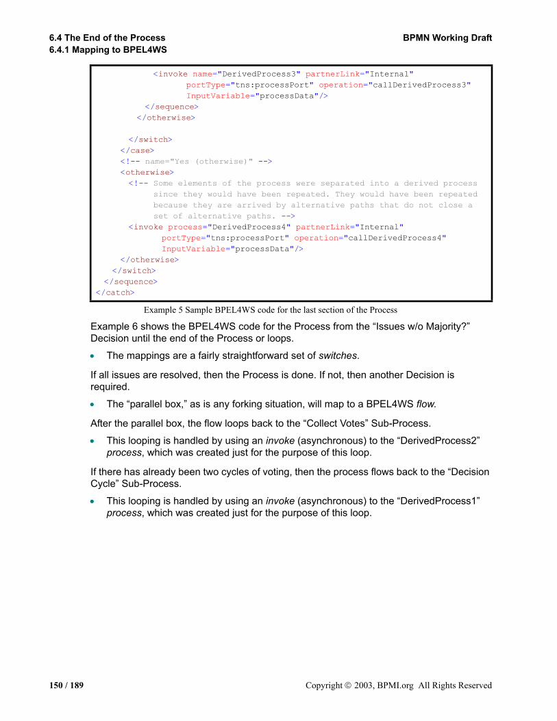
6.4 The End of the Process BPMN Working Draft6.4.1 Mapping to BPEL4WS
Example 5 Sample BPEL4WS code for the last section of the Process
Example 6 shows the BPEL4WS code for the Process from the “Issues w/o Majority?” Decision until the end of the Process or loops.
• The mappings are a fairly straightforward set of switches.
If all issues are resolved, then the Process is done. If not, then another Decision is required.
• The “parallel box,” as is any forking situation, will map to a BPEL4WS flow.
After the parallel box, the flow loops back to the “Collect Votes” Sub-Process.
• This looping is handled by using an invoke (asynchronous) to the “DerivedProcess2” process, which was created just for the purpose of this loop.
If there has already been two cycles of voting, then the process flows back to the “Decision Cycle” Sub-Process.
• This looping is handled by using an invoke (asynchronous) to the “DerivedProcess1” process, which was created just for the purpose of this loop.
<invoke name="DerivedProcess3" partnerLink="Internal" portType="tns:processPort" operation="callDerivedProcess3" InputVariable="processData"/>
</sequence></otherwise>
</switch></case><!-- name="Yes (otherwise)" --><otherwise><!-- Some elements of the process were separated into a derived process
since they would have been repeated. They would have been repeated because they are arrived by alternative paths that do not close a set of alternative paths. -->
<invoke process="DerivedProcess4" partnerLink="Internal" portType="tns:processPort" operation="callDerivedProcess4" InputVariable="processData"/>
</otherwise></switch>
</sequence></catch>
150 / 189 Copyright 2003, BPMI.org All Rights Reserved
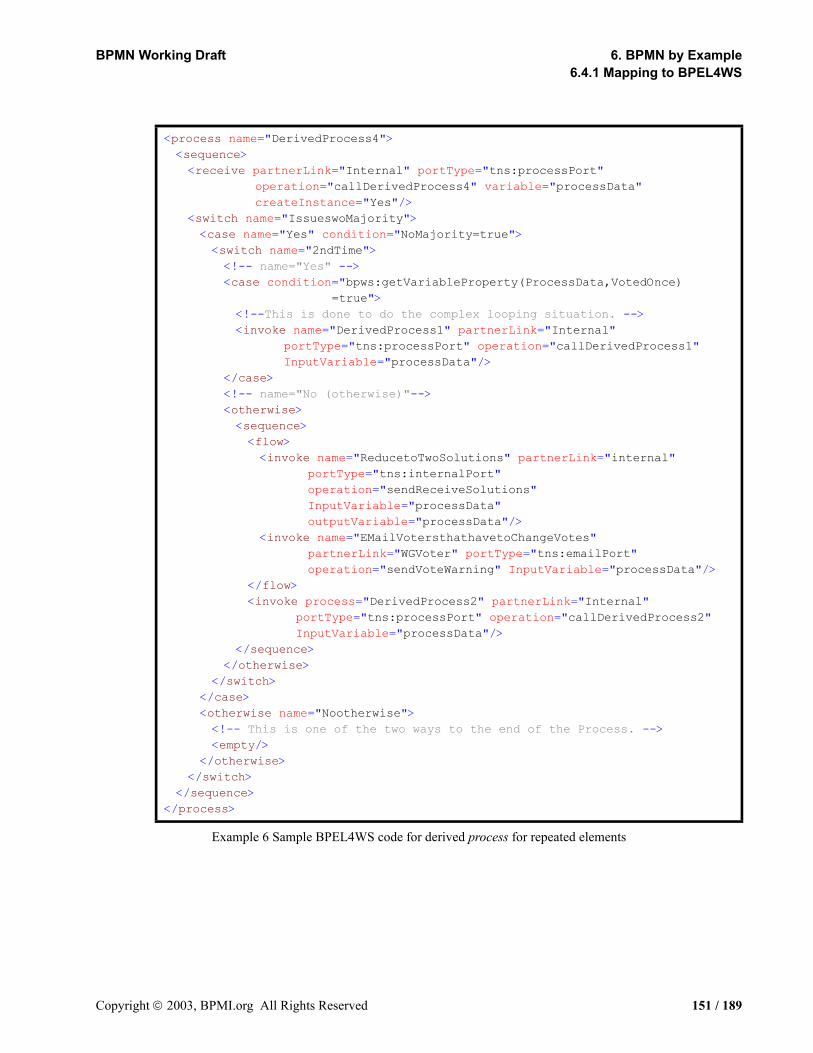
BPMN Working Draft 6. BPMN by Example6.4.1 Mapping to BPEL4WS
Example 6 Sample BPEL4WS code for derived process for repeated elements
<process name="DerivedProcess4"><sequence><receive partnerLink="Internal" portType="tns:processPort"
operation="callDerivedProcess4" variable="processData" createInstance="Yes"/>
<switch name="IssueswoMajority"><case name="Yes" condition="NoMajority=true"><switch name="2ndTime"><!-- name="Yes" --><case condition="bpws:getVariableProperty(ProcessData,VotedOnce)
=true"><!--This is done to do the complex looping situation. --><invoke name="DerivedProcess1" partnerLink="Internal"
portType="tns:processPort" operation="callDerivedProcess1" InputVariable="processData"/>
</case><!-- name="No (otherwise)"--><otherwise><sequence><flow><invoke name="ReducetoTwoSolutions" partnerLink="internal"
portType="tns:internalPort" operation="sendReceiveSolutions" InputVariable="processData" outputVariable="processData"/>
<invoke name="EMailVotersthathavetoChangeVotes" partnerLink="WGVoter" portType="tns:emailPort" operation="sendVoteWarning" InputVariable="processData"/>
</flow><invoke process="DerivedProcess2" partnerLink="Internal"
portType="tns:processPort" operation="callDerivedProcess2" InputVariable="processData"/>
</sequence></otherwise>
</switch></case><otherwise name="Nootherwise"><!-- This is one of the two ways to the end of the Process. --><empty/>
</otherwise></switch>
</sequence></process>
Copyright 2003, BPMI.org All Rights Reserved 151 / 189

6.4 The End of the Process BPMN Working Draft6.4.1 Mapping to BPEL4WS
152 / 189 Copyright 2003, BPMI.org All Rights Reserved

BPMN Working Draft
7. Mapping to XML LanguagesThis section will cover the mappings to BPEL4WS that are derived by analyzing the relationships between the elements described in the above sections. For example, a Decision object marks the beginning of a switch, but the end of the switch will have to be determined by tracing the alternative paths from the Decision and finding the point in the Process where all the alternative paths have merged, which may be the end of the Process. The strings of activities that lie between the Decision and the merging point will comprise the activity sets for each of the switch cases. The location of the final merging point could be complicated by the inclusion of intermediary Decisions and/or parallel sections of the Process. BPMN does not include a specific merging object that will be tied one-to-one with a specific Decision object that will allow the quick identification of the merging point. Likewise, BPMN does not have paired objects to mark the beginning and end of parallel activities that would fit into the BPEL4WS flow element. Furthermore, BPMN is cyclical in that it allows Sequence Flows to connect to upstream objects so that a modeler can easily visualize looping situations. The exact configuration of these loops will determine how they are mapped to BPM execution constructions, some of which are acyclic.
To determine the appropriate merging and joining points that are needed to construct execution language elements such as switch, the configuration of the Process needs to be analyzed. The mechanism we are proposing is called Token Analysis. This involves the creation of a conceptual Token that will “traverse” all the Sequence Flows of the Process. The Token will have a hierarchical TokenID set that will expand/or contract based on the forking and joining and/or splitting and merging that occurs throughout the Process. By matching the TokenID set of Tokens that arrive at objects that have multiple incoming Sequence Flows, it will be possible to determine the boundaries of execution language structured activities.
Editor’s Note: the finalization of the Mapping to Execution Languages through Token Analysis is an open issue and will be developed further in a later version of the specification. Refer to the section entitled “Open Issues” on page 169 for a complete list of the issues open for BPMN.
7.1 Defining Token Generation for execution Language Mapping
<for parallel> This means a separate Token will be generated to traverse each of the paths. Each Token will have two aspects to its identity. The first aspect, called the TokenID, has to with the single path that is being forked—this identity will be common to all the new Tokens. The second aspect, called the SubTokenID, which is a TokenID nested with a higher-level TokenID, will be unique for each the new paths. The start of a business process will have a single Token with a TokenID. Multiple levels of SubTokenIDs will be created as forks occur through the Process. The number of SubTokenIDs for each fork will be known. The TokenID sets will be used to join the Tokens from a given fork back together.
Copyright 2003, BPMI.org All Rights Reserved 153 / 189
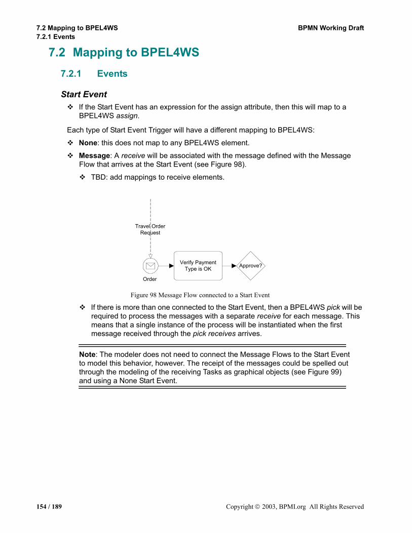
7.2 Mapping to BPEL4WS BPMN Working Draft7.2.1 Events
7.2 Mapping to BPEL4WS7.2.1 Events
Start EventIf the Start Event has an expression for the assign attribute, then this will map to a BPEL4WS assign.
Each type of Start Event Trigger will have a different mapping to BPEL4WS:
None: this does not map to any BPEL4WS element.
Message: A receive will be associated with the message defined with the Message Flow that arrives at the Start Event (see Figure 98).
TBD: add mappings to receive elements.
Figure 98 Message Flow connected to a Start Event
If there is more than one connected to the Start Event, then a BPEL4WS pick will be required to process the messages with a separate receive for each message. This means that a single instance of the process will be instantiated when the first message received through the pick receives arrives.
Note: The modeler does not need to connect the Message Flows to the Start Event to model this behavior, however. The receipt of the messages could be spelled out through the modeling of the receiving Tasks as graphical objects (see Figure 99) and using a None Start Event.
Verify PaymentType is OK
Order
Approve?
Travel OrderRequest
154 / 189 Copyright 2003, BPMI.org All Rights Reserved

BPMN Working Draft 7. Mapping to XML Languages7.2.1 Events
Figure 99 Process Instantiation through Message Receiving Task
Timer: TBD.
Rule: TBD.
Link: this will map to the receive element.
Multiple: this will map to a combination of receive elements.
End EventIf the End Event has an expression for the assign attribute, then this will map to a BPEL4WS assign.
The assign will precede any other BPEL4WS elements that are the result of other End Event attributes (see below).
Each type of End Event Result will have a different mapping to BPEL4WS:
None: this does not map to any BPEL4WS element. However, it marks the end of a path within the Process and will be used to define the boundaries of complex BPEL4WS elements.
Message: A BPEL4WS reply will be associated with the message defined with the Message Flow that leaves the End Event (see Figure 100).
Figure 100 Message Flow leaving an End Event
Verify PaymentType is OK
Order
Travel OrderRequest
Receive Request Approve?
Default(New)
Established withgood Credit
Established withpoor Credit
Include ApologyText
Include History ofTransactions
Include StandardText
RejectionResponse
Type ofCustomer?
RejectionMessage
Copyright 2003, BPMI.org All Rights Reserved 155 / 189

7.2 Mapping to BPEL4WS BPMN Working Draft7.2.1 Events
Note: The modeler does not need to connect the Message Flows from the End Event to model this behavior, however. The sending of the messages could be modeled through the modeling of the sending Tasks as graphical objects (see Figure 101)
Figure 101 Message Flow from Task that precedes the End Event
Exception: this will map to a throw element.
Compensation: this will map to a compensate element.
Link: this will map to the invoke element. <more here>
Terminate: this will map to the terminate element.
Return: this does not map a specific BPEL4WS element, but it does mark the end of the activities that exist within a compensation handler.
Multiple: this will map to a combination of invoke, throw, fault, and compensation elements.
Intermediate EventIf the Intermediate Event has an expression for the assign attribute, then this will map to a BPEL4WS assign.
Each type of Intermediate Event Trigger will have a different mapping to BPEL4WS:
Message:
If the Intermediate Event is within the normal flow of the Process: this will map to a receive.
If the Intermediate Event is attached to the boundary of an activity: this will map to an onMessage element within a scope.
Timer:
If the Intermediate Event is within the normal flow of the Process: this will map to a wait.
The TimeDate attribute maps to the until attribute of the wait.
Default(New)
Established withgood Credit
Established withpoor Credit
Include ApologyText
Include History ofTransactions
Include StandardText
RejectionMessage
Send RejectionResponse
Type ofCustomer?
156 / 189 Copyright 2003, BPMI.org All Rights Reserved
BPMN Working Draft 7. Mapping to XML Languages7.2.2 Activities
The TimeCycle attribute maps to the for attribute of the wait.
If the Intermediate Event is attached to the boundary of an activity: this will map to a wait element, followed by a throw. A flow with a scope will also be created to contain the elements generated from the activity and the Intermediate Event so that they run in parallel. The scope will have a catch to correspond with the throw. The throw will also follow the elements generate from the activity so that the flow will end.
Exception: this will map to a catch element within a scope.
Compensation (must be attached to the boundary of an activity): this will map to an compensationHandler element within a scope.
Rule (must be attached to the boundary of an activity): TBD.
Link (must follow a Decision): this will map to the onMessage element of a pick.
Multiple (must be attached to the boundary of an activity): this will map to a combination of onMessage, onAlarm, compensationHandler, onSignal, throw, catch, and wait elements within a context.
7.2.2 Activities
Sub-ProcessThere are four possibilities, depending on the Message Flows that attach to the Sub-Process boundary:
A Sub-Process that has no Message Flows attached to its boundary will map to the BPEL4WS invoke. This will invoke another web service, which is another process.
A Sub-Process that has an incoming Message Flow attached to its boundary will map to a BPEL4WS receive followed by a BPEL4WS invoke.
A Sub-Process that has an outgoing Message Flow attached to its boundary will map to the BPEL4WS invoke followed by a BPEL4WS reply.
A Sub-Process that has both an incoming and an outgoing Message Flow attached to its boundary will map to a BPEL4WS receive followed by a BPEL4WS invoke followed by a BPEL4WS reply.
Sub-Process properties will map as follows:
For an Independent SubProcessType the modeler will have to create the referenced Process independently (with a different name) and then assign the Process to the Sub-Process object. The referenced process will be called with the BPEL4WS invoke.
InputMap will be mapped to an assign that will precede the invoke.
OutputMap will be mapped to an assign that will follow the invoke.
The mapping for the Transaction attribute is TBD.
If the LoopType is Standard then the Sub-Process will be wrapped by a BPEL4WS while.
A Before TestTime will map to the BPEL4WS while.
Copyright 2003, BPMI.org All Rights Reserved 157 / 189
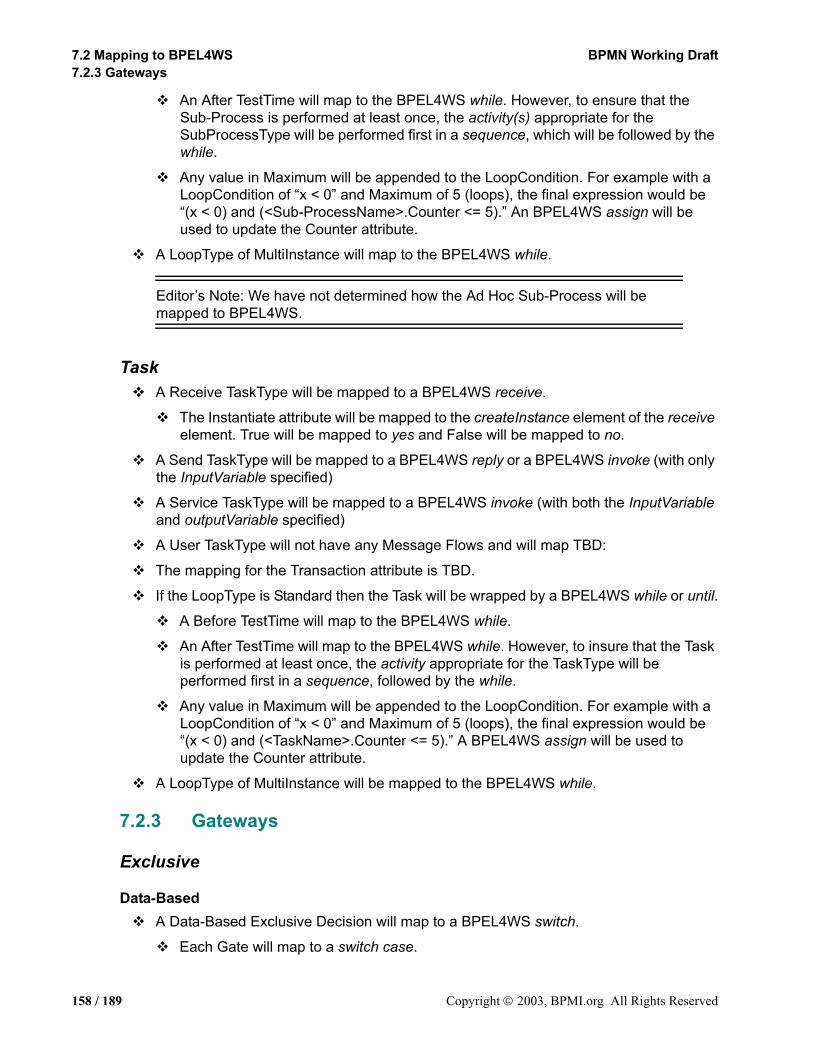
7.2 Mapping to BPEL4WS BPMN Working Draft7.2.3 Gateways
An After TestTime will map to the BPEL4WS while. However, to ensure that the Sub-Process is performed at least once, the activity(s) appropriate for the SubProcessType will be performed first in a sequence, which will be followed by the while.
Any value in Maximum will be appended to the LoopCondition. For example with a LoopCondition of “x < 0” and Maximum of 5 (loops), the final expression would be “(x < 0) and (<Sub-ProcessName>.Counter <= 5).” An BPEL4WS assign will be used to update the Counter attribute.
A LoopType of MultiInstance will map to the BPEL4WS while.
Editor’s Note: We have not determined how the Ad Hoc Sub-Process will be mapped to BPEL4WS.
TaskA Receive TaskType will be mapped to a BPEL4WS receive.
The Instantiate attribute will be mapped to the createInstance element of the receive element. True will be mapped to yes and False will be mapped to no.
A Send TaskType will be mapped to a BPEL4WS reply or a BPEL4WS invoke (with only the InputVariable specified)
A Service TaskType will be mapped to a BPEL4WS invoke (with both the InputVariable and outputVariable specified)
A User TaskType will not have any Message Flows and will map TBD:
The mapping for the Transaction attribute is TBD.
If the LoopType is Standard then the Task will be wrapped by a BPEL4WS while or until.
A Before TestTime will map to the BPEL4WS while.
An After TestTime will map to the BPEL4WS while. However, to insure that the Task is performed at least once, the activity appropriate for the TaskType will be performed first in a sequence, followed by the while.
Any value in Maximum will be appended to the LoopCondition. For example with a LoopCondition of “x < 0” and Maximum of 5 (loops), the final expression would be “(x < 0) and (<TaskName>.Counter <= 5).” A BPEL4WS assign will be used to update the Counter attribute.
A LoopType of MultiInstance will be mapped to the BPEL4WS while.
7.2.3 Gateways
Exclusive
Data-BasedA Data-Based Exclusive Decision will map to a BPEL4WS switch.
Each Gate will map to a switch case.
158 / 189 Copyright 2003, BPMI.org All Rights Reserved

BPMN Working Draft 7. Mapping to XML Languages7.2.3 Gateways
The Condition for the Sequence Flow associated with the Gate will map to the condition for a switch case.
The Default Gate will map to the Switch otherwise case.
The activities that follow the conditions will be included within the activity (usually a sequence) for that condition. The exact content of the activity will depend on the configuration of the Process. Details of how the configuration will be mapped to the activity set can be found in the section entitled “Mapping to XML Languages” on page 153.
Event-BasedAn Event-Based Exclusive Gateway will map to a BPEL4WS pick.
A Receive Task, which is the Target of a Sequence Flow associated with the Gate, will map to an onMessage element within the pick.
The Attributes of the Receive Task will map to the appropriate elements of the onMessage, such as operation and portType.
A Message Intermediate Event, which is the Target of a Sequence Flow associated with the Gate, will map to an onMessage element within the pick.
The Attributes of the Message Intermediate Event will map to the appropriate elements of the onMessage, such as operation and portType.
A Timer Intermediate Event, which is the Target of a Sequence Flow associated with the Gate, will map to an onAlarm element within the pick.
The Timedate attribute of the Event will map to the until element of the onAlarm element.
The Timecycle attribute of the Event will map to the for element of the onAlarm element.
An Exception Intermediate Event, which is the Target of a Sequence Flow associated with the Gate, will map to TBD.
A Link Intermediate Event, which is the Target of a Sequence Flow associated with the Gate, will map to TBD.
A Rule Intermediate Event, which is the Target of a Sequence Flow associated with the Gate, will map to TBD.
The activities that follow Targets of the Gate’s Sequence Flow, will be included within the activity (usually a sequence) for that pick element. The exact content of the activity will depend on the configuration of the Process. Details of how the configuration will be mapped to the activity can be found in the section entitled “Mapping to XML Languages” on page 153.
Copyright 2003, BPMI.org All Rights Reserved 159 / 189
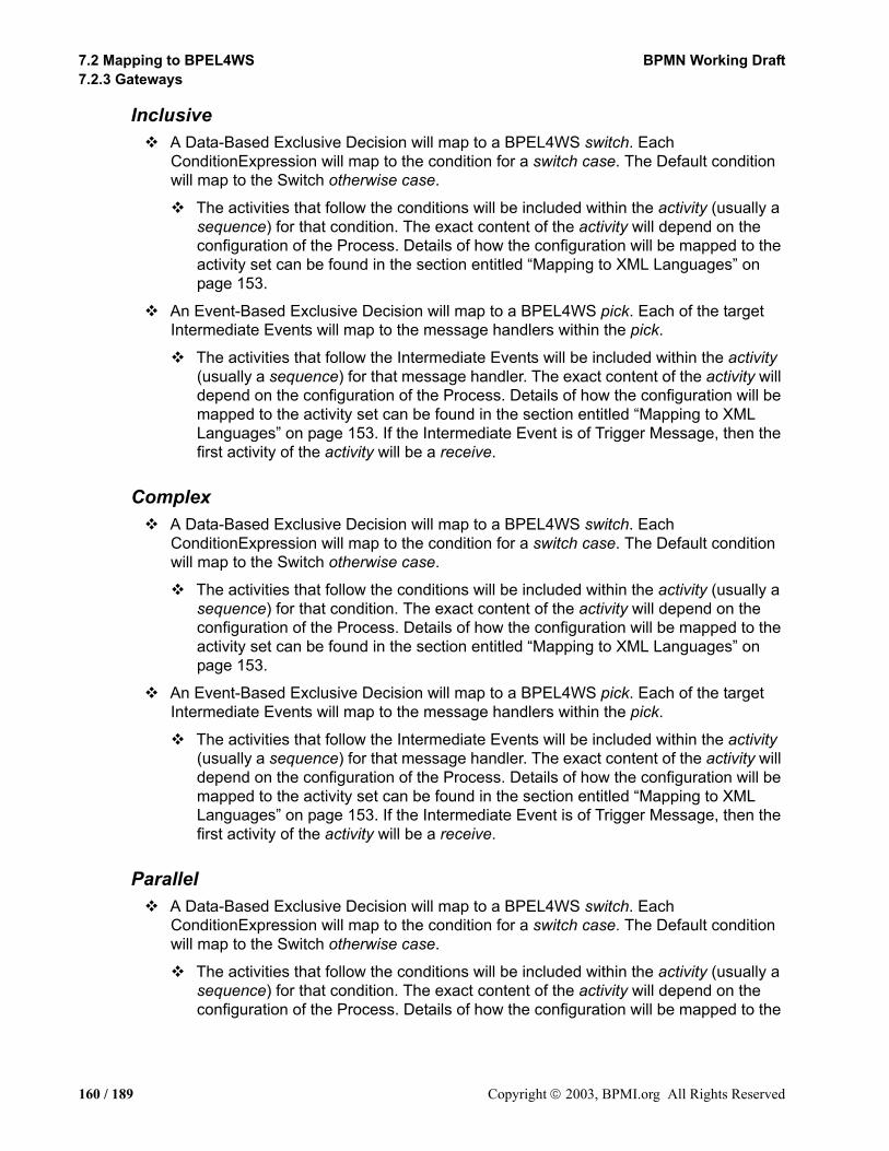
7.2 Mapping to BPEL4WS BPMN Working Draft7.2.3 Gateways
InclusiveA Data-Based Exclusive Decision will map to a BPEL4WS switch. Each ConditionExpression will map to the condition for a switch case. The Default condition will map to the Switch otherwise case.
The activities that follow the conditions will be included within the activity (usually a sequence) for that condition. The exact content of the activity will depend on the configuration of the Process. Details of how the configuration will be mapped to the activity set can be found in the section entitled “Mapping to XML Languages” on page 153.
An Event-Based Exclusive Decision will map to a BPEL4WS pick. Each of the target Intermediate Events will map to the message handlers within the pick.
The activities that follow the Intermediate Events will be included within the activity (usually a sequence) for that message handler. The exact content of the activity will depend on the configuration of the Process. Details of how the configuration will be mapped to the activity set can be found in the section entitled “Mapping to XML Languages” on page 153. If the Intermediate Event is of Trigger Message, then the first activity of the activity will be a receive.
ComplexA Data-Based Exclusive Decision will map to a BPEL4WS switch. Each ConditionExpression will map to the condition for a switch case. The Default condition will map to the Switch otherwise case.
The activities that follow the conditions will be included within the activity (usually a sequence) for that condition. The exact content of the activity will depend on the configuration of the Process. Details of how the configuration will be mapped to the activity set can be found in the section entitled “Mapping to XML Languages” on page 153.
An Event-Based Exclusive Decision will map to a BPEL4WS pick. Each of the target Intermediate Events will map to the message handlers within the pick.
The activities that follow the Intermediate Events will be included within the activity (usually a sequence) for that message handler. The exact content of the activity will depend on the configuration of the Process. Details of how the configuration will be mapped to the activity set can be found in the section entitled “Mapping to XML Languages” on page 153. If the Intermediate Event is of Trigger Message, then the first activity of the activity will be a receive.
ParallelA Data-Based Exclusive Decision will map to a BPEL4WS switch. Each ConditionExpression will map to the condition for a switch case. The Default condition will map to the Switch otherwise case.
The activities that follow the conditions will be included within the activity (usually a sequence) for that condition. The exact content of the activity will depend on the configuration of the Process. Details of how the configuration will be mapped to the
160 / 189 Copyright 2003, BPMI.org All Rights Reserved

BPMN Working Draft 7. Mapping to XML Languages7.2.4 Pool
activity set can be found in the section entitled “Mapping to XML Languages” on page 153.
An Event-Based Exclusive Decision will map to a BPEL4WS pick. Each of the target Intermediate Events will map to the message handlers within the pick.
The activities that follow the Intermediate Events will be included within the activity (usually a sequence) for that message handler. The exact content of the activity will depend on the configuration of the Process. Details of how the configuration will be mapped to the activity set can be found in the section entitled “Mapping to XML Languages” on page 153. If the Intermediate Event is of Trigger Message, then the first activity of the activity will be a receive.
7.2.4 PoolPools do not have any specific Mapping to Execution Languages. However, a Pool is associated with a mapping to a specific lower level language. For example, one Pool may encompass a BPEL4WS document while another Pool might encompass an ebXML BPSS document.
7.2.5 LaneLanes do not have any specific Mapping to Execution Languages. They are designed to help organize and communicate how activities are grouped in a business process.
7.2.6 ArtifactsAs a general rule, Artifacts do not map to BPEL4WS elements. They provide detailed information about how data will interact with the flow objects and flows of Processes.
However, Text Annotations can map to the documentation element of BPM execution languages. If the Annotation is associated with a flow object and that object has a straight-forward mapping to a BPM execution language element, then the text of the Annotation will be placed in the documentation element of that object. If there is no straight-forward mapping to a BPM execution language element, then the text of the Annotation will be appended to the documentation element of the process.
For any new Artifact that is added to a BDP through a modeling tool, it will have to be determined whether or not that Artifact maps to any BPEL4WS element.W
7.2.7 Sequence FlowA Sequence Flow may not have a specific mapping to a BPEL4WS in most situations. However, when there is a section of the Diagram that contains parallel activities, then Sequence Flow may map to the link element. Details of this mapping are TBD. In general, the set of Sequence Flows within a Pool will determine how BPEL4WS elements are derived and the boundaries of those elements.
7.2.8 Message FlowA Message Flow does not have a specific mapping to a BPEL4WS element. It represents a message that is send through a WSDL operation that is referenced in a BPEL4WS receive, reply, or invoke.
Copyright 2003, BPMI.org All Rights Reserved 161 / 189

7.2 Mapping to BPEL4WS BPMN Working Draft7.2.9 Association
7.2.9 AssociationAn Association does not have a specific mapping to an execution language element. These objects and the artifacts they connect to provide additional information for the reader of the BPMN Diagram, but do not directly affect the execution of the Process.
7.2.10 Exception FlowFor an activity with an Intermediate Event attached to its boundary:
The activity will be placed inside a scope.
A faultHandler element will be defined for the scope.
If an Intermediate Event is of Trigger Exception and no name has been specified for the error, then a catchAll element will be added to the faultHandler element.
If an Intermediate Event is of Trigger Exception and a name has been specified for the error, then a catch element will be added to the faultHandler element with the name of the error placed in the faultName attribute.
If an Intermediate Event is of Trigger Message, then:
The source activity will be placed inside a flow (which is inside the scope)
A sequence will also be placed within the flow
The first element of the sequence will be a receive that will wait for the message identified in the Intermediate Event.
The next element of the sequence will be a throw that will have a faultName with a name that is constructed from the Message Name with “Fault” appended.
A catch element will be added to the faultHandler element (within the scope) with the “<message name>Fault” error placed in the faultName attribute.
If the Intermediate Event is of Trigger Timer, then:
The source activity will be placed inside a flow (which is inside the scope)
A sequence will also be placed within the flow
The first element of the sequence will be a wait that will use the time information identified in the Intermediate Event.
The next element of the sequence will be a throw that will have a faultName with a name that is constructed from the Intermediate Event Name with “Fault” appended.
A catch element will be added to the faultHandler element (within the scope) with the “<Intermediate Event name>Fault” error placed in the faultName attribute.
If there is only one activity that flows from the Intermediate Event, then the appropriate mapping for this activity will be used as the activity for the faultHandler.
A sequence will be used as the activity for the faultHandler if the mapping is complex or there are more than one activity that follows the Intermediate Event.
162 / 189 Copyright 2003, BPMI.org All Rights Reserved
BPMN Working Draft 7. Mapping to XML Languages7.2.11 Compensation Flow
7.2.11 Compensation FlowFor an activity with a Compensation Intermediate Event attached to its boundary:
The activity will be placed inside a scope.
A compensationHandler element will be defined for the scope.
If there is only one activity that flows from the Intermediate Event, then the appropriate mapping for this activity will be used as the activity for the compensationHandler.
A sequence will be used as the activity for the compensationHandler if the mapping is complex or there are more than one activity that follows the Intermediate Event.
Copyright 2003, BPMI.org All Rights Reserved 163 / 189

7.2 Mapping to BPEL4WS BPMN Working Draft7.2.11 Compensation Flow
164 / 189 Copyright 2003, BPMI.org All Rights Reserved
BPMN Working Draft 8. References
8. References8.1 Normative
RFC-2119Key words for use in RFCs to Indicate Requirement Levels, S. Bradner, IETF RFC 2119, March 1997
http://www.ietf.org/rfc/rfc2119.txt
BPEL4WS(BPEL4WS) 1.1, IBM/Microsoft/BEA/SAP/Siebel, May, 2003
http://www-106.ibm.com/developerworks/webservices/library/ws-bpel/
8.2 Non-Normative
Activity ServiceAdditional Structuring Mechanism for the OTS specification, OMG, June 1999
http://www.omg.org
J2EE Activity Service for Extended Transactions (JSR 95), JCP
http://www.jcp.org/jsr/detail/95.jsp
Business Process ModelingJean-Jacques Dubray, “A Novel Approach for Modeling Business Process Definitions,” 2002
http://www.ebpml.org/ebpml2.2.doc
Business Transaction ProtocolOASIS BTP Technical Committee, June, 2002
http://www.oasis-open.org/committees/download.php/1184/2002-06-03.BTP_cttee_spec_1.0.pdf
BPML(BPML) 1.0, BPMI, January 2003
http://www.BPMI.org
Dublin Core Meta DataDublin Core Metadata Element Set, Dublin Core Metadata Initiative
http://dublincore.org/documents/dces/
Copyright 2003, BPMI.org All Rights Reserved 165 / 189
8.2 Non-Normative BPMN Working Draft
ebXML BPSSJean-Jacques Dubray, “A new model for ebXML BPSS Multi-party Collaborations and Web Services Choreography,” 2002
http://www.ebpml.org/ebpml.doc
OMG UMLUnified Modeling Language Specification, OMG, June 1999
http://www.omg.org
Open Nested TransactionsConcepts and Applications of Multilevel Transactions and Open Nested Transactions, Gerhard Weikum, Hans-J. Schek, 1992
http://citeseer.nj.nec.com/weikum92concepts.html
RDFRDF Vocabulary Description Language 1.0: RDF Schema, W3C Working Draft
http://www.w3.org/TR/rdf-schema/
SOAP 1.2SOAP Version 1.2 Part 1: Messaging Framework, W3C Working Draft
http://www.w3.org/TR/soap12-part1/
SOAP Version 1.2 Part21: Adjuncts, W3C Working Draft
http://www.w3.org/TR/soap12-part2/
UDDIUniversal Description, Discovery and Integration, Ariba, IBM and Microsoft, UDDI.org.
http://www.uddi.org
URIUniform Resource Identifiers (URI): Generic Syntax, T. Berners-Lee, R. Fielding, L. Masinter, IETF RFC 2396, August 1998
http://www.ietf.org/rfc/rfc2396.txt
WfMC GlossaryWorkflow Management Coalition Terminology and Glossary.
http://www.wfmc.org/standards/docs.htm
166 / 189 Copyright 2003, BPMI.org All Rights Reserved
BPMN Working Draft 8. References
Web Services Transaction(WS-Transaction) 1.0, IBM/Microsoft/BEA, August, 2002
http://www-106.ibm.com/developerworks/webservices/library/ws-transpec/
WSDLWeb Services Description Language (WSDL) 1.1, W3C Note, 15 March 2001
http://www.w3.org/TR/wsdl.html
XML 1.0 (Second Edition)Extensible Markup Language (XML) 1.0, Second Edition, Tim Bray et al., eds., W3C, 6 October 2000
http://www.w3.org/TR/REC-xml
XML-NamespacesNamespaces in XML, Tim Bray et al., eds., W3C, 14 January 1999
http://www.w3.org/TR/REC-xml-names
XML-SchemaXML Schema Part 1: Structures, Henry S. Thompson, David Beech, Murray Maloney, Noah Mendelsohn, W3C, 2 May 2001
http://www.w3.org/TR/xmlschema-1//
XML Schema Part 2: Datatypes, Paul V. Biron and Ashok Malhotra, eds., W3C, 2 May 2001
http://www.w3.org/TR/xmlschema-2/
XPathXML Path Language (XPath) 1.0, James Clark and Steve DeRose, eds., W3C, 16 November 1999
http://www.w3.org/TR/xpath
Copyright 2003, BPMI.org All Rights Reserved 167 / 189

8.2 Non-Normative BPMN Working Draft
168 / 189 Copyright 2003, BPMI.org All Rights Reserved
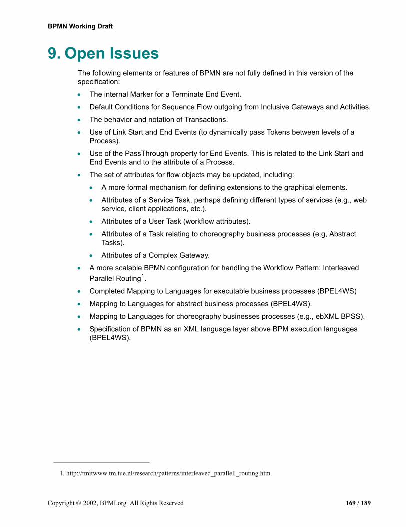
BPMN Working Draft
9. Open IssuesThe following elements or features of BPMN are not fully defined in this version of the specification:
• The internal Marker for a Terminate End Event.
• Default Conditions for Sequence Flow outgoing from Inclusive Gateways and Activities.
• The behavior and notation of Transactions.
• Use of Link Start and End Events (to dynamically pass Tokens between levels of a Process).
• Use of the PassThrough property for End Events. This is related to the Link Start and End Events and to the attribute of a Process.
• The set of attributes for flow objects may be updated, including:
• A more formal mechanism for defining extensions to the graphical elements.
• Attributes of a Service Task, perhaps defining different types of services (e.g., web service, client applications, etc.).
• Attributes of a User Task (workflow attributes).
• Attributes of a Task relating to choreography business processes (e.g, Abstract Tasks).
• Attributes of a Complex Gateway.
• A more scalable BPMN configuration for handling the Workflow Pattern: Interleaved Parallel Routing1.
• Completed Mapping to Languages for executable business processes (BPEL4WS)
• Mapping to Languages for abstract business processes (BPEL4WS).
• Mapping to Languages for choreography businesses processes (e.g., ebXML BPSS).
• Specification of BPMN as an XML language layer above BPM execution languages (BPEL4WS).
1. http://tmitwww.tm.tue.nl/research/patterns/interleaved_parallell_routing.htm
Copyright 2002, BPMI.org All Rights Reserved 169 / 189

8.2 Non-Normative BPMN Working Draft
170 / 189 Copyright 2003, BPMI.org All Rights Reserved
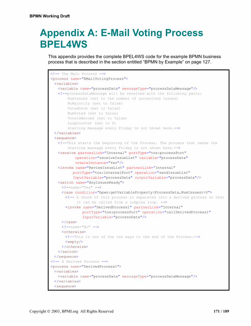
BPMN Working Draft
Appendix A: E-Mail Voting Process BPEL4WS
This appendix provides the complete BPEL4WS code for the example BPMN business process that is described in the section entitled “BPMN by Example” on page 127.
<!-- The Main Process --><process name="EMailVotingProcess"><variables><variable name="processData" messageType="processDataMessage"/><!--processDataMessage will be received with the following parts:
NumIssues (set to the number of unresolved Issues) NoMajority (set to false) VotedOnce (set to false) NumVoted (set to false) VotersWarned (set to false) LoopCounter (set to 0)
starting message every Friday is not shown here.--></variables><sequence><!--This starts the beginning of the Process. The process that sends the
starting message every Friday is not shown here.--><receive partnerLink="Internal" portType="tns:processPort"
operation="receiveIssueList" variable="processData" createInstance="Yes"/>
<invoke name="ReviewIssueList" partnerLink=“Internal" portType="tns:internalPort" operation="sendIssueList" InputVariable="processData" outputVariable="processData"/>
<switch name="AnyIssuesReady"><!--name="Yes" --><case condition="bpws:getVariableProperty(ProcessData,NumIssues)>0"><!-- A chunk of this process is separated into a derived process so that
it can be called from a complex loop. --><invoke name="DerivedProcess1" partnerLink="Internal"
portType="tns:processPort" operation="callDerivedProcess1" InputVariable="processData"/>
</case><!--name="No" --><otherwise><!--This is one of the two ways to the end of the Process.--><empty/>
</otherwise></switch>
</sequence><!-- A Derived Process --><process name="DerivedProcess1"><variables><variable name="processData" messageType="processDataMessage"/>
</variables><sequence>
Copyright 2003, BPMI.org All Rights Reserved 171 / 189

Appendix A: E-Mail Voting Process BPEL4WS BPMN Working Draft
<receive partnerLink="Internal" portType="tns:processPort" operation="callDerivedProcess1" variable="processData" createInstance="Yes"/>
<!--The first Sub-Process has a loop condition, so it is within a while--><while condition="bpws:getVariableProperty(ProcessData,DiscussionOver)
=false" andbpws:getVariableProperty(ProcessData,loopCounter) > 0"><!--This calls the first Sub-Process--><sequence> <invoke process="DiscussionCycle" partnerLink="Internal"
portType="tns:processPort operation="callDiscussionCycle" inputVariable="processData" outputVariable="processData"/>
<assign><copy><from expression=
"bpws:getVariableProperty(ProcessData,LoopCounter)+1"/><to variable="processData" part="LoopCounter"/>
</copy></assign>
</sequence></while><!--This calls the first another derived process to handle the rest of the
work--><invoke name="DerivedProcess2" partnerLink="Internal"
portType="tns:processPort" operation="callDerivedProcess2" InputVariable="processData"/>
</sequence></process></process><!-- A Derived Process --><process name="DerivedProcess2"><!-- This starts the middle section of the process. --><variables><variable name="processData" messageType="processDataMessage"/>
</variables><sequence><receive partnerLink="Internal" portType="tns:processPort"
operation="callDerivedProcess2" variable="processData" createInstance="Yes"/>
<invoke name="AnnounceIssuesforVote" partnerLink="WGVoter" portType="tns:emailPort" operation="sendVoteAnnouncement" InputVariable="processData"/>
<invoke name="DerivedProcess3" partnerLink="Internal" portType="tns:processPort" operation="callDerivedProcess3" InputVariable="processData"/>
</sequence></process><!-- A Derived Process --><process name="DerivedProcess3"><!--this calls the second Sub-Process. After the Collect Votes Sub-Process
times out, the rest of the process will be in the fault handler of that process. Calls from there will loop back into other processes.-->
<variables><variable name="processData" messageType="processDataMessage"/>
</variables>
172 / 189 Copyright 2003, BPMI.org All Rights Reserved

BPMN Working Draft Appendix A: E-Mail Voting Process BPEL4WS
<sequence><receive partnerLink="Internal" portType="tns:processPort"
operation="callDerivedProcess3" variable="processData" createInstance="Yes"/>
<invoke name="CollectVotes" partnerLink="Internal" portType="tns:processPort" operation="callCollectVotes" InputVariable="processData"/>
</sequence></process><!-- A Derived Process --><process name="DerivedProcess4"><variables><variable name="processData" messageType="processDataMessage"/>
</variables><sequence><receive partnerLink="Internal" portType="tns:processPort"
operation="callDerivedProcess4" variable="processData" createInstance="Yes"/>
<switch name="IssueswoMajority"><case name="Yes"
condition="bpws:getVariableProperty(ProcessData,NoMajority)=true"><switch name="2ndTime"><!-- name="Yes" --><case condition="bpws:getVariableProperty(ProcessData,VotedOnce)
=true"><!--This is done to do the complex looping situation. --><invoke name="DerivedProcess1" partnerLink="Internal"
portType="tns:processPort" operation="callDerivedProcess1" InputVariable="processData"/>
</case><!-- name="No (otherwise)" --><otherwise><sequence><flow><invoke name="ReducetoTwoSolutions" partnerLink="internal"
portType="tns:internalPort" operation="sendReceiveSolutions" InputVariable="processData" outputVariable="processData"/>
<invoke name="EMail Voters that have to Change Votes" partnerLink="WGVoter" portType="tns:emailPort" operation="sendVoteWarning" InputVariable="processData"/>
</flow><invoke process="DerivedProcess2" partnerLink="Internal"
portType="tns:processPort" operation="callDerivedProcess2" InputVariable="processData"/>
</sequence></otherwise>
</switch></case><otherwise name="Nootherwise"><!-- This is one of the two ways to the end of the Process. --><empty/>
</otherwise>
Copyright 2003, BPMI.org All Rights Reserved 173 / 189

Appendix A: E-Mail Voting Process BPEL4WS BPMN Working Draft
</switch></sequence>
</process><!-- A User Built Process --><process name="DiscussionCycle"><!--This defines the first Sub-Process. --><variables><variable name="processData" messageType="processDataMessage"/>
</variables><sequence><receive partnerLink="Internal" portType="tns:processPort"
operation="callDiscussionCycle" variable="processData" createInstance="Yes"/>
<invoke name="AnnounceIssuesforDiscussion" partnerLink="WGVoter" portType="tns:emailPort" operation="sendDiscussionAnnouncement" InputVariable="processData"/>
<flow><links><link name="CheckCalendarforConferenceCalltoWaituntilThursday9am"/><link name="CheckCalendarforConferenceCalltoEmpty"/><link name="WaituntilThursday9amtoModerateConferenceCallDiscussion"/>
</links><!-- This is the first of the three paths of the fork. --><scope><flow><invoke name="ModerateEmailDiscussion" partnerLink="internal"
portType="tns:internalPort" operation="sendDiscussion" InputVariable="processData" outputVariable="processData"/>
<sequence><wait name="7days" for="P7D"/><throw faultName="7days_fault"/>
</sequence></flow><faultHander><catch faultName="7days_fault"><invoke name="ReviewStatusofDiscussion" partnerLink="internal"
portType="tns:internalPort" operation="receiveDiscussionStatus" InputVariable="processData" outputVariable="processData"/>
</catch></faultHander>
</scope><!-- This is the second of the three paths of the fork. --><sequence><wait name="Delay6daysfromDiscussionAnnouncement" for="P6D"/><invoke name="EMailDiscussionDeadlineWarning" partnerLink="WGVoter"
portType="tns:emailPort" operation="sendDiscussionWarning" InputVariable="processData">
</invoke></sequence>
174 / 189 Copyright 2003, BPMI.org All Rights Reserved
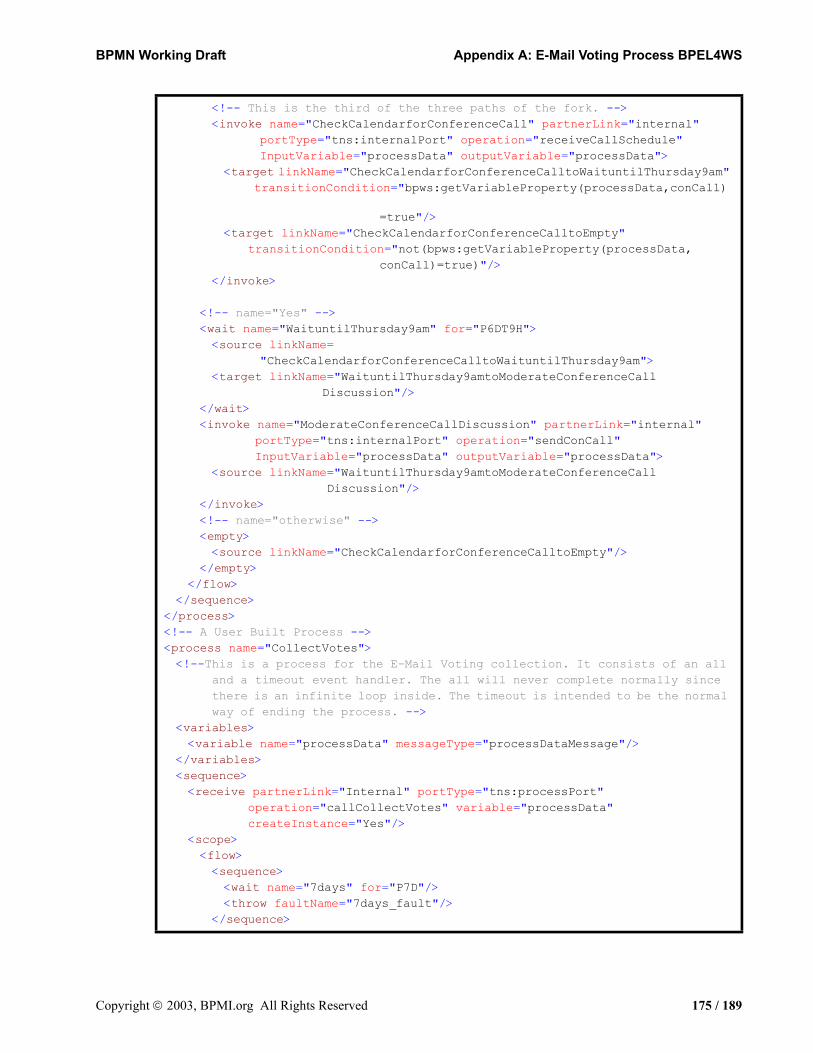
BPMN Working Draft Appendix A: E-Mail Voting Process BPEL4WS
<!-- This is the third of the three paths of the fork. --><invoke name="CheckCalendarforConferenceCall" partnerLink="internal"
portType="tns:internalPort" operation="receiveCallSchedule" InputVariable="processData" outputVariable="processData">
<target linkName="CheckCalendarforConferenceCalltoWaituntilThursday9am" transitionCondition="bpws:getVariableProperty(processData,conCall)
=true"/><target linkName="CheckCalendarforConferenceCalltoEmpty"
transitionCondition="not(bpws:getVariableProperty(processData,conCall)=true)"/>
</invoke>
<!-- name="Yes" --><wait name="WaituntilThursday9am" for="P6DT9H"><source linkName=
"CheckCalendarforConferenceCalltoWaituntilThursday9am"><target linkName="WaituntilThursday9amtoModerateConferenceCall
Discussion"/></wait><invoke name="ModerateConferenceCallDiscussion" partnerLink="internal"
portType="tns:internalPort" operation="sendConCall" InputVariable="processData" outputVariable="processData">
<source linkName="WaituntilThursday9amtoModerateConferenceCall Discussion"/>
</invoke><!-- name="otherwise" --><empty><source linkName="CheckCalendarforConferenceCalltoEmpty"/>
</empty></flow>
</sequence></process><!-- A User Built Process --><process name="CollectVotes"><!--This is a process for the E-Mail Voting collection. It consists of an all
and a timeout event handler. The all will never complete normally since there is an infinite loop inside. The timeout is intended to be the normal way of ending the process. -->
<variables><variable name="processData" messageType="processDataMessage"/>
</variables><sequence><receive partnerLink="Internal" portType="tns:processPort"
operation="callCollectVotes" variable="processData" createInstance="Yes"/>
<scope><flow><sequence><wait name="7days" for="P7D"/><throw faultName="7days_fault"/>
</sequence>
Copyright 2003, BPMI.org All Rights Reserved 175 / 189
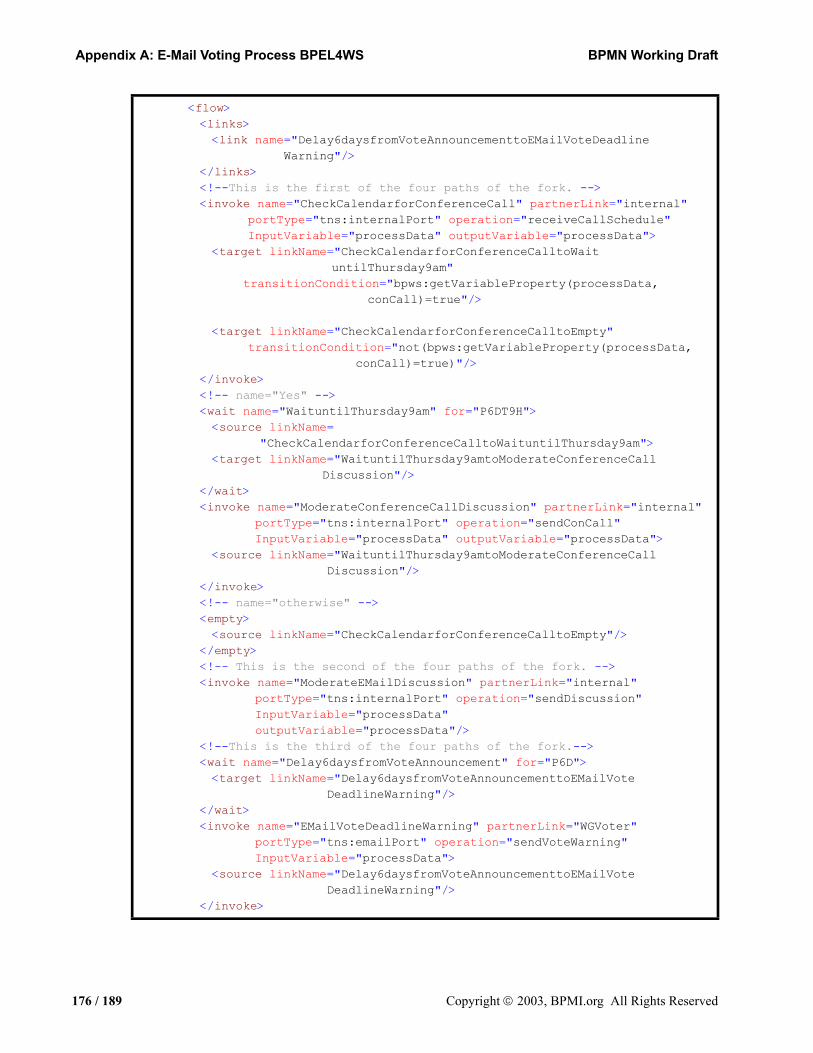
Appendix A: E-Mail Voting Process BPEL4WS BPMN Working Draft
<flow><links><link name="Delay6daysfromVoteAnnouncementtoEMailVoteDeadline
Warning"/></links><!--This is the first of the four paths of the fork. --><invoke name="CheckCalendarforConferenceCall" partnerLink="internal"
portType="tns:internalPort" operation="receiveCallSchedule" InputVariable="processData" outputVariable="processData">
<target linkName="CheckCalendarforConferenceCalltoWaituntilThursday9am"
transitionCondition="bpws:getVariableProperty(processData,conCall)=true"/>
<target linkName="CheckCalendarforConferenceCalltoEmpty"transitionCondition="not(bpws:getVariableProperty(processData,
conCall)=true)"/></invoke><!-- name="Yes" --><wait name="WaituntilThursday9am" for="P6DT9H"><source linkName=
"CheckCalendarforConferenceCalltoWaituntilThursday9am"><target linkName="WaituntilThursday9amtoModerateConferenceCall
Discussion"/></wait><invoke name="ModerateConferenceCallDiscussion" partnerLink="internal"
portType="tns:internalPort" operation="sendConCall" InputVariable="processData" outputVariable="processData">
<source linkName="WaituntilThursday9amtoModerateConferenceCall Discussion"/>
</invoke><!-- name="otherwise" --><empty><source linkName="CheckCalendarforConferenceCalltoEmpty"/>
</empty><!-- This is the second of the four paths of the fork. --><invoke name="ModerateEMailDiscussion" partnerLink="internal"
portType="tns:internalPort" operation="sendDiscussion" InputVariable="processData" outputVariable="processData"/>
<!--This is the third of the four paths of the fork.--><wait name="Delay6daysfromVoteAnnouncement" for="P6D"><target linkName="Delay6daysfromVoteAnnouncementtoEMailVote
DeadlineWarning"/></wait><invoke name="EMailVoteDeadlineWarning" partnerLink="WGVoter"
portType="tns:emailPort" operation="sendVoteWarning" InputVariable="processData">
<source linkName="Delay6daysfromVoteAnnouncementtoEMailVote DeadlineWarning"/>
</invoke>
176 / 189 Copyright 2003, BPMI.org All Rights Reserved
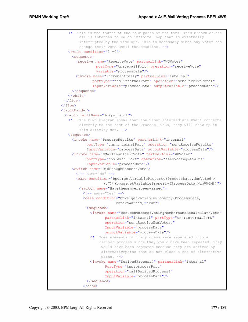
BPMN Working Draft Appendix A: E-Mail Voting Process BPEL4WS
<!--This is the fourth of the four paths of the fork. This branch of the all is intended to be an infinite loop that is eventually interrupted by the Time Out. This is necessary since any voter can change their vote until the deadline. -->
<while condition="1!=0"><sequence><receive name="ReceiveVote" partnerLink="WGVoter"
portType="tns:emailPort" operation="receiveVote" variable="processData"/>
<invoke name="IncrementTally" partnerLink="internal" portType="tns:internalPort" operation="sendReceiveTotal" InputVariable="processData" outputVariable="processData"/>
</sequence></while>
</flow></flow><faultHander><catch faultName="7days_fault"><!-- The BPMN Diagram shows that the Timer Intermediate Event connects
directly to the rest of the Process. Thus, they will show up in this activity set. -->
<sequence><invoke name="PrepareResults" partnerLink="internal"
portType="tns:internalPort" operation="sendReceiveResults" InputVariable="processData" outputVariable="processData"/>
<invoke name="EMailResultsofVote" partnerLink="WGVoter" portType="tns:emailPort" operation="sendVotingResults" InputVariable="processData"/>
<switch name="DidEnoughMembersVote"><!-- name="No" --><case condition="bpws:getVariableProperty(ProcessData,NumVoted)>
(.7)*(bpws:getVariableProperty(ProcessData,NumVWGM))"><switch name="Havethemembersbeenwarned"><!-- name="Yes" --><case condition="bpws:getVariableProperty(ProcessData,
VotersWarned)=true"><sequence><invoke name="ReducenumberofVotingMembersandRecalculateVote"
partnerLink="internal" portType="tns:internalPort" operation="sendReceiveNumVoters" InputVariable="processData" outputVariable="processData"/>
<!--Some elements of the process were separated into a derived process since they would have been repeated. They would have been repeated because they are arrived by alternativepaths that do not close a set of alternative paths. -->
<invoke name="DerivedProcess4" partnerLink="Internal" PortType="tns:processPort" operation="callDerivedProcess4" InputVariable="processData"/>
</sequence></case>
Copyright 2003, BPMI.org All Rights Reserved 177 / 189

Appendix A: E-Mail Voting Process BPEL4WS BPMN Working Draft
<!-- name="No (otherwise)" --><otherwise><sequence><invoke name="ReannounceVotewithwarningtovotingmembers"
partnerLink="WGVoter" portType="tns:emailPort" operation="sendReannounceVote" InputVariable="processData" outputVariable="processData"/>
<invoke name="DerivedProcess3" partnerLink="Internal" portType="tns:processPort" operation="callDerivedProcess3" InputVariable="processData"/>
</sequence></otherwise>
</switch></case><!-- name="Yes (otherwise)" --><otherwise><!-- Some elements of the process were separated into a derived
process since they would have been repeated. They would have been repeated because they are arrived by alternative that do not close a set of alternative paths. -->
<invoke process="DerivedProcess4" partnerLink="Internal" portType="tns:processPort" operation="callDerivedProcess4" InputVariable="processData"/>
</otherwise></switch>
</sequence></catch>
</faultHander></scope>
</sequence></process>
178 / 189 Copyright 2003, BPMI.org All Rights Reserved

BPMN Working Draft
Appendix B: GlossaryA, C, D, E, F, I, J, L, M, N, O, P, R, S, T, U
AActivity: An activity is a generic term for work that company or
organization performs via business processes. An activity can be atomic or non-atomic (compound). The types of activities that are a part of a Process Model are: Process, Sub-Process, and Task.
Abstract Process: An Abstract Process represents the interactions between a private business process and another process or participant.
AND-Join: (from the WfMC Glossary1) An AND-Join is a point in the Process where two or more parallel executing activities converge into a single common thread of Sequence Flow. See “Join.”
AND-Split: (from the WfMC Glossary2) An AND-Split is a point in the Process where a single thread of Sequence Flow splits into two or more threads which are executed in parallel within the Process, allowing multiple activities to be executed simultaneously. See “Fork.”
Arbitrary Cycles: (From the Workflow Patterns Initiative2). Pattern #11: A point in a workflow process when one or more activities can be done repeatedly3.
Artifact: An artifact is a graphical object that provides supporting information about the Process or elements within the Process. However, it does not directly affect the flow of the Process. BPMN has standardized the shape of a Data Object. Other examples of artifacts include critical success factors and milestones.
Association: An Association is a dotted graphical line that is used to associate information and artifacts with flow objects. Text and graphical non-flow objects can be associated with the flow objects and flows.
1. The underlined terms in this definition were changed from the original definition. “Process” is used in place of “workflow.” “Sequence Flow” is used in place of “control.”
2. http://tmitwww.tm.tue.nl/research/patterns/patterns.htm3. http://tmitwww.tm.tue.nl/research/patterns/arbitrary_cycles.htm
Copyright 2003, BPMI.org All Rights Reserved 179 / 189
Appendix B: Glossary BPMN Working Draft
Atomic Activity: An atomic activity is an activity not broken down to a finer level of Process Model detail. It is a leaf in the tree-structure hierarchy of Process activities. Graphically it will appear as a Task in BPMN.
BBusiness Analyst: A Business Analyst is an individual within an
organization who defines, manages, or monitors Business Processes. They are usually distinguished from the IT specialists or programmers who implement the Business Process within a BPMS.
Business Process: A Business Process is displayed within a Business Process Diagram (BPD). A Business Process contains one or more Processes.
Business Process Diagram: A Business Process Diagram (BPD) is the diagram that is specified by BPMN. A BPD uses the graphical elements and that semantics that support these elements as defined in this specification.
Business Process Management: Business Process Management (BPM) encompasses the discovery, design, and deployment of business processes. In addition, BPM includes the executive, administrative, and supervisory control of those processes1.
BPM System: The technology that enables BPM.
CCancel Activity: (From the Workflow Patterns Initiative2). Pattern #20:
An enabled activity is disabled, i.e. a thread waiting for the execution of an activity is removed3.
Cancel Case: (From the Workflow Patterns Initiative2). Pattern #21: A case, i.e.workflow instance, is removed completely4.
Choreography: Choreography is an ordered sequence of B2B message exchanges.
Collaboration: Collaboration is the act of sending messages between any two Participants in a BPMN model. The two Participants represent two separate BPML processes.
Collaboration Process: A Collaboration Process depicts the interactions between two or more business entities.
1. From “Business Process Management: the Third Wave,” by Howard Smith and Peter Fingar, pg 4. 2003, Meghan-Kiffer Press. ISBN 0-929652-33-9
2. http://tmitwww.tm.tue.nl/research/patterns/patterns.htm3. http://tmitwww.tm.tue.nl/research/patterns/cancel_activity.htm4. http://tmitwww.tm.tue.nl/research/patterns/cancel_case.htm
180 / 189 Copyright 2003, BPMI.org All Rights Reserved
BPMN Working Draft Appendix B: Glossary
Collapsed Sub-Process: A Collapsed Sub-Process is a Sub-Process that hides its flow details. The Collapsed Sub-Process object uses a marker to distinguish it as a Sub-Process, rather than a Task. The marker is a small square with a plus sign (+) inside.
Compensation Flow: Compensation Flow is defines the set of activities that are performed during the roll-back of a transaction to compensate for activities that were performed during the normal flow of the Process. Compensation can also be called from a Compensate End or Intermediate Event.
Compound Activity: A compound activity is an activity that has detail that is defined as a flow of other activities. It is a branch (or trunk) in the tree-structure hierarchy of Process activities. Graphically, it will appear as a Process or Sub-Process in BPMN.
Controlled Flow: Flow that proceeds from one Flow Object to another, via a Sequence Flow link, but is subject to either conditions or dependencies from other flow as defined by a Gateway. Typically, this is seen as a Sequence flow between two activities, with a conditional indicator (mini-diamond) or a Sequence Flow connected to a Gateway.
DDecision: Decisions are locations within a business process
where the Sequence Flow can take two or more alternative paths. This is basically the “fork in the road” for a process. For a given performance (or instance) of the process, only one of the forks can be taken. A Decision is a type of Gateway. See “Or-Split.”
Deferred Choice: (From the Workflow Patterns Initiative1). Pattern #17: A point in the workflow process where one of several branches is chosen. In contrast to the XOR-split, the choice is not made explicitly (e.g. based on data or a decision) but several alternatives are offered to the environment. However, in contrast to the AND-split, only one of the alternatives is executed. This means that once the environment activates one of the branches the other alternative branches are withdrawn. It is important to note that the choice is delayed until the processing in one of the alternative branches is actually started, i.e. the moment of choice is as late as possible2.
1. http://tmitwww.tm.tue.nl/research/patterns/patterns.htm2. http://tmitwww.tm.tue.nl/research/patterns/deferred_choice.htm
Copyright 2003, BPMI.org All Rights Reserved 181 / 189189

Appendix B: Glossary BPMN Working Draft
Discriminator: (From the Workflow Patterns Initiative1). Pattern #8: The discriminator is a point in a workflow process that waits for a number of incoming branches to complete before activating the subsequent activity. From that moment on it waits for all remaining branches to complete and “ignores'' them. Once all incoming branches have been triggered, it resets itself so that it can be triggered again1.
EEnd Event: As the name implies, the End Event indicates where a
process will end. In terms of Sequence Flow, the End Event ends the flow of the Process, and thus, will not have any outgoing Sequence Flows. An End Event can have a specific Result that will appear as a marker within the center of the End Event shape. End Event Results are Message, Exception, Compensation, Link, and Multiple. The End Event shares the same basic shape of the Start Event and Intermediate Event, a circle, but is drawn with a thick single line
Event Context: An Event Context is the set of activities that can be interrupted by an exception (Intermediate Event). This can be one activity or a group of activities in an expanded Sub-Process.
Exception: An Exception is an event that occurs during the performance of the process that causes normal flow of the process to be diverted exclusively from normal flow. Exceptions can be generated by a time out, fault, message, etc.
Exception Flow: Exception Flow is a set of Sequence Flow that originates from an Intermediate Event that is attached to the boundary of an activity. The Process will not traverse this flow unless an Exception occurs during the performance of that activity (through an Intermediate Event).
Exclusive Choice: (From the Workflow Patterns Initiative2). Pattern #4: A point in the workflow process where, based on a decision or workflow control data, one of several branches is chosen3.
1. http://tmitwww.tm.tue.nl/research/patterns/discriminator.htm2. http://tmitwww.tm.tue.nl/research/patterns/patterns.htm3. http://tmitwww.tm.tue.nl/research/patterns/exclusive_choice.htm
182 / 189 Copyright 2003, BPMI.org All Rights Reserved
BPMN Working Draft Appendix B: Glossary
Expanded Sub-Process: An Expanded Sub-Process is a Sub-Process that exposes its flow detail within the context of its Parent Process. It will maintain its rounded rectangle shape, but will be enlarged to a size sufficient to display the flow objects within.
FFlow: A Flow is a graphical line connecting two objects in a
BPD. There are two types of Flow: Sequence Flow and Message Flow, each with their own line style. Flow is also used in a generic sense (and lowercase) to describe how Tokens will traverse Sequence Flow from the Start Event to an End Event.
Flow Object: A flow object is one of the set of following graphical objects: Events, Activities, and Gateways.
Fork: A fork is a point in the Process where a single flow is divided into two or more flows. It is a mechanism that will allow activities to be performed concurrently, rather than serially. BPMN uses multiple outgoing Sequence Flow or an Parallel Gateway to perform a Fork. See “AND-Split.”
IImplicit Termination: (From the Workflow Patterns Initiative1). Pattern #12: A
given subprocess should be terminated when there is nothing else to be done. In other words, there are no active activities in the workflow and no other activity can be made active (and at the same time the workflow is not in deadlock)2.
Interleaved Parallel Routing: (From the Workflow Patterns Initiative1). Pattern #18: A set of activities is executed in an arbitrary order: Each activity in the set is executed, the order is decided at run-time, and no two activities are executed at the same moment (i.e.no two activities are active for the same workflow instance at the same time)3.
1. http://tmitwww.tm.tue.nl/research/patterns/patterns.htm2. http://tmitwww.tm.tue.nl/research/patterns/implicit_termination.htm3. http://tmitwww.tm.tue.nl/research/patterns/interleaved_parallel_routing.htm
Copyright 2003, BPMI.org All Rights Reserved 183 / 189189
Appendix B: Glossary BPMN Working Draft
Intermediate Event: An Intermediate Event is an event that occurs after a Process has been started. It will affect the flow of the process, but will not start or (directly) terminate the process. An Intermediate Event will show where messages or delays are expected within the Process, disrupt the normal flow through exception handling, or show the extra flow required for compensating a transaction. The Intermediate Event shares the same basic shape of the Start Event and End Event, a circle, but is drawn with a thin double line.
JJoin: A Join is a point in the Process where two or more
parallel Sequence Flows are combined into one Sequence Flow. BPMN uses an Parallel Gateway to perform a Join. See “AND-Join.”
LLane: An Lane is a sub-partition within a Pool and will extend
the entire length of the Pool, either vertically or horizontally. Lanes are used to organize and categorize activities within a Pool. The meaning of the Lanes is up to the modeler.
MMerge: A Merge is a point in the process where two or more
alternative Sequence Flows are combined into one Sequence Flow. BPMN uses multiple incoming Sequence Flow or an XOR Gateway to perform a Merge. See “OR-Join.”
Message: A Message is the object that is transmitted through a Message Flow. The Message will have an identity that can be used for alternative branching of a Process through the Event-Based Exclusive Gateway.
Message Flow: A Message Flow is a dashed line that is used to show the flow of messages between two entities that are prepared to send and receive them. In BPMN, two separate Pools in the Diagram will represent the two entities.
184 / 189 Copyright 2003, BPMI.org All Rights Reserved

BPMN Working Draft Appendix B: Glossary
Milestone: (From the Workflow Patterns Initiative1). Pattern #19: The enabling of an activity depends on the case being in a specified state, i.e.the activity is only enabled if a certain milestone has been reached which did not expire yet. Consider three activities A, B, and C. Activity A is only enabled if activity B has been executed and C has not been executed yet, i.e.A is not enabled before the execution B and A is not enabled after the execution C2.
Multiple Choice: (From the Workflow Patterns Initiative1). Pattern #6: A point in the workflow process where, based on a decision or workflow control data, one or more branches are chosen3.
Multiple Instances: (From the Workflow Patterns Initiative1). Patterns #13-16: There are four defined patterns. 1. For one case an activity is enabled multiple times. The number of instances of a given activity for a given case is known at design time. 2. For one case an activity is enabled multiple times. The number of instances of a given activity for a given case is variable and may depend on characteristics of the case or availability of resources, but is known at some stage during runtime, before the instances of that activity have to be created. 3. For one case an activity is enabled multiple times. The number of instances of a given activity for a given case is not known during design time, nor it is known at any stage during runtime, before the instances of that activity have to be created. 4 For one case an activity is enabled multiple times. The number of instances may not be known at design time. After completing all instances of that activity another activity has to be started4.
Multiple Merge: (From the Workflow Patterns Initiative1). Pattern #7: Multi-merge is a point in a workflow process where two or more branches reconverge without synchronization. If more than one branch gets activated, possibly concurrently, the activity following the merge is started once for every incoming branch that gets activated5.
1. http://tmitwww.tm.tue.nl/research/patterns/patterns.htm2. http://tmitwww.tm.tue.nl/research/patterns/milestone.htm3. http://tmitwww.tm.tue.nl/research/patterns/multiple_choice.htm4. http://tmitwww.tm.tue.nl/research/patterns/patterns.htm5. http://tmitwww.tm.tue.nl/research/patterns/multiple_merge.htm
Copyright 2003, BPMI.org All Rights Reserved 185 / 189189

Appendix B: Glossary BPMN Working Draft
NN-out-of-M-Join: (From the Workflow Patterns Initiative1). Pattern #9: N-
out-of-M Join is a point in a workflow process where M parallel paths converge into one. The subsequent activity should be activated once N paths have completed. Completion of all remaining paths should be ignored. Similarly to the discriminator, once all incoming branches have “fired”, the join resets itself so that it can fire again1.
Normal Flow: Normal Flow is the flow that originates from a Start Event and continues through activities via alternative and parallel paths until it ends at an End Event.
OOR-Join: (from the WfMC Glossary2) An Or-Join is a point in the
Process where two or more alternative activity(s) Process branches re-converge to a single common activity as the next step within the Process. (As no parallel activity execution has occurred at the join point, no synchronization is required.) See “Merge.”
OR-Split: (from the WfMC Glossary1) An OR-Split is a point in the Process where a single thread of Sequence Flow makes a decision upon which branch to take when encountered with multiple alternative Process branches. See “Decision.”
PParallel Split: (From the Workflow Patterns Initiative3). Pattern #2:
Parallel split is required when two or more activities need to be executed in parallel. Parallel split is easily supported by most workflow engines except for the most basic scheduling systems that do not require any degree of concurrency4.
Parent Process: A Parent Process is the Process that holds a Sub-Process within its boundaries.
1. http://tmitwww.tm.tue.nl/research/patterns/n-out-of-m_join.htm2. The underlined terms in this definition were changed from the original definition. “Process” is used in place of
“workflow.” “Sequence Flow” is used in place of “control.”3. http://tmitwww.tm.tue.nl/research/patterns/patterns.htm4. http://tmitwww.tm.tue.nl/research/patterns/parallel_split.htm
186 / 189 Copyright 2003, BPMI.org All Rights Reserved

BPMN Working Draft Appendix B: Glossary
Participant: A Participant is a business entity, usually a company, company division, or a customer, which controls or is responsible for a business process. If Pools are used, then a Participant would be associated with one Pool.
Pool: A Pool is a “swimlane” and a graphical container for partitioning a set of activities from other Pools, usually in the context of B2B situations. It is a square-cornered rectangle that is drawn with a solid single line. A Pool acts as the container for the Sequence Flow between activities. The Sequence Flow can cross the boundaries between Lanes of a Pool, but cannot cross the boundaries of a Pool. The interaction between Pools, e.g., in a B2B context, is shown through Message Flows.
Private Business Process: A private business process is internal to a specific organization and is the type of process that has been generally called a workflow or BPM process. A single private business process will map to a single BPML document.
Process: A Process is any activity performed within a company or organization. In BPMN a Process is depicted as a network of flow objects, which are a set of other activities and the controls that sequence them.
RResult: A Result is consequence of reaching an End Event.
Results can be of different types, including: Message, Exception, Compensation, Link, and Multiple.
SSequence: (From the Workflow Patterns Initiative1). Pattern #1:
Sequence is the most basic workflow pattern. It is required when there is a dependency between two or more tasks so that one task cannot be started (scheduled) before another task is finished2.
Sequence Flow: A Sequence Flow is a solid graphical line that is used to show the order that activities will be performed in a Process. Each Flow has only one source and only one target.
1. http://tmitwww.tm.tue.nl/research/patterns/patterns.htm2. http://tmitwww.tm.tue.nl/research/patterns/sequence.htm
Copyright 2003, BPMI.org All Rights Reserved 187 / 189189

Appendix B: Glossary BPMN Working Draft
Simple Merge: (From the Workflow Patterns Initiative1). Pattern #5: A point in the workflow process where two or more alternative branches come together without synchronization. In other words the merge will be triggered once any of the incoming transitions are triggered1.
Start Event: A Start Event indicates where a particular Process will start. In terms of Sequence Flow, the Start Event starts the flow of the Process, and thus, will not have any incoming Sequence Flows. A Start Event can have a Trigger that indicates how the Process starts: Message, Timer, Rule, Link, or Multiple. The Start Event shares the same basic shape of the Intermediate Event and End Event, a circle, but is drawn with a single thin line
Sub-Process: A Sub-Process is Process that is included within another Process. The Sub-Process can be in a collapsed view that hides its details. A Sub-Process can be in an expanded view that shows its details within the view of the Process in which it is contained. A Sub-Process shares the same shape as the Task, which is a rectangle that has rounded corners.
Swimlane: A swimlane is a graphical container for partitioning a set of activities from other activities. BPMN has two different types of swimlanes. See “Pool” and “Lane.”
Synchronizing Join: (From the Workflow Patterns Initiative2). Pattern #10: A point in the workflow process where multiple paths converge into one single thread. If more than one path is taken, synchronization of the active threads needs to take place. If only one path is taken, the alternative branches should reconverge without synchronization3.
Synchronization: (From the Workflow Patterns Initiative1). Pattern #3: Synchronization is required when an activity can be started only when two parallel threads complete4.
1. http://tmitwww.tm.tue.nl/research/patterns/simple_merge.htm2. http://tmitwww.tm.tue.nl/research/patterns/patterns.htm3. http://tmitwww.tm.tue.nl/research/patterns/synchronizing_join.htm4. http://tmitwww.tm.tue.nl/research/patterns/synchronization.htm
188 / 189 Copyright 2003, BPMI.org All Rights Reserved
BPMN Working Draft Appendix B: Glossary
TTask: A Task is an atomic activity that is included within a
Process. A Task is used when the work in the Process is not broken down to a finer level of Process Model detail. Generally, an end-user and/or an application are used to perform the Task when it is executed. A Task object shares the same shape as the Sub-Process, which is a rectangle that has rounded corners.
Token: A Token is a descriptive construct used to describe how the flow of a process will proceed at runtime. By tracking how the Token traverses the flow objects, gets diverted through alternative paths, and gets split into parallel paths, the normal Sequence Flow should be completely definable.A Token will have a unique identity that can be used to separate multiple Tokens that may exist because of concurrent process instances or the splitting of the Token for parallel processing within a single process instance.
Transaction: A Transaction is a set of coordinated activities carried out by independent, loosely-coupled systems in accordance with a contractually defined business relationship. This coordination leads to an agreed, consistent, and verifiable outcome across all participants.
Trigger: A Trigger is a mechanism that signals the start of a business process. Triggers are associated with a Start Events and Intermediate Events and can be of the type: Message, Timer, Rule, Link, and Multiple.
UUncontrolled Flow: Flow that proceeds, unrestricted, from one Flow Object
to another, via a Sequence Flow link, without any dependencies on another flow or any conditional expressions. Typically, this is seen as a Sequence flow between two activities, without a conditional indicator (mini-diamond) or any intervening Gateway.
Copyright 2003, BPMI.org All Rights Reserved 189 / 189189