business process modelling for internet …...monitoring things remotely over the internet such as...
TRANSCRIPT
BUSINESS PROCESS MODELLING
FOR INTERNET OF THINGS
A THESIS SUBMITTED TO AUCKLAND UNIVERSITY OF TECHNOLOGY
IN PARTIAL FULFILMENT OF THE REQUIREMENTS FOR THE DEGREE OF
MASTER OF PHILOSOPHY
Supervisors
Dr Jian Yu
Dr Alan T Litchfield
February 2018
By
Kusum Pradeepika Ratnayake
School of Engineering, Computer and Mathematical Sciences
Abstract
Business process management is an integral part of a business. Internet of things (IoT)
is an emerging and fast improving technology. Traditional business process models
have not given much attention to IoT. Yet, it has become a necessity to incorporate IoT
systems and components when modelling business processes to obtain the many benefits
IoT offers. Therefore, we aimed to fill this gap by identifying business process modelling
requirements for IoT, i.e. IoT modelling elements and to demonstrate the applicability
of them in a business process model. We identified seven key IoT modelling elements
after deriving them from a typical problem scenario. We investigated the properties of
IoT components in detail, illustrating them in class hierarchy design and describing
common properties in super classes. We extended BPMN 2.0 in designing these IoT
elements and implemented them in an IoT related business process model. We also
developed a web based IoT aware BPMN and XPDL editor tool by extending an existing
BPMN editor. Furthermore, we evaluated the applicability of this IoT aware BPMN
modelling tool with a case study.
2
Contents
Abstract 2
Attestation of Authorship 9
Acknowledgements 10
1 Introduction 111.1 Background and Research Objectives . . . . . . . . . . . . . . . . . . . . 111.2 Research Questions . . . . . . . . . . . . . . . . . . . . . . . . . . . . . 151.3 Research Contributions . . . . . . . . . . . . . . . . . . . . . . . . . . . 151.4 Thesis Structure . . . . . . . . . . . . . . . . . . . . . . . . . . . . . . . 16
2 Literature Review 172.1 Introduction . . . . . . . . . . . . . . . . . . . . . . . . . . . . . . . . . . 172.2 Internet of Things (IoT) . . . . . . . . . . . . . . . . . . . . . . . . . . . 18
2.2.1 History of IoT . . . . . . . . . . . . . . . . . . . . . . . . . . . . 182.2.2 IoT Protocols . . . . . . . . . . . . . . . . . . . . . . . . . . . . 192.2.3 Middleware Support for IoT . . . . . . . . . . . . . . . . . . . . . 21
2.3 Business Process Modelling (BPM) . . . . . . . . . . . . . . . . . . . . 302.3.1 History of Business Process Modelling . . . . . . . . . . . . . . 312.3.2 Business Process Modelling . . . . . . . . . . . . . . . . . . . . 322.3.3 Business Process Modelling Languages (BPMLs) . . . . . . . 36
2.4 BPMN Modelling Frameworks for IoT . . . . . . . . . . . . . . . . . . . 412.4.1 Framework: uBPMN . . . . . . . . . . . . . . . . . . . . . . . . 422.4.2 Framework: SPU . . . . . . . . . . . . . . . . . . . . . . . . . . 442.4.3 Framework: BPMN4WSN . . . . . . . . . . . . . . . . . . . . . 502.4.4 Framework: Things of IoT in BPMN . . . . . . . . . . . . . . . 542.4.5 Framework: Crowdsourcing . . . . . . . . . . . . . . . . . . . . 572.4.6 Framework: Event Element for IoT . . . . . . . . . . . . . . . . . 612.4.7 Framework: IoT Devices as Resources . . . . . . . . . . . . . . 652.4.8 Summary . . . . . . . . . . . . . . . . . . . . . . . . . . . . . . . 68
2.5 Conclusion . . . . . . . . . . . . . . . . . . . . . . . . . . . . . . . . . . 73
3
3 Running Scenario and Requirements Derivation 753.1 Introduction . . . . . . . . . . . . . . . . . . . . . . . . . . . . . . . . . . 753.2 Problem Scenario . . . . . . . . . . . . . . . . . . . . . . . . . . . . . . . 763.3 Requirements Derivation . . . . . . . . . . . . . . . . . . . . . . . . . . 80
3.3.1 Requirement 1 (R1): Sensor as the Business Process ModellingRequirement for IoT . . . . . . . . . . . . . . . . . . . . . . . . 80
3.3.2 Requirement 2 (R2): Actuator as the Business Process Model-ling Requirement for IoT . . . . . . . . . . . . . . . . . . . . . . 90
3.3.3 Requirement 3 (R3): Reader as the Business Process ModellingRequirement for IoT . . . . . . . . . . . . . . . . . . . . . . . . 93
3.3.4 Requirement 4 (R4): Collector as the Business Process Model-ling Requirement for IoT . . . . . . . . . . . . . . . . . . . . . . 97
3.3.5 Requirement 5 (R5): Event streaming (event stream processingunits) as the Business Process Modelling Requirement for IoT 98
3.3.6 Requirement 6 (R6): Specific data object as the Business Pro-cess Modelling Requirement for IoT . . . . . . . . . . . . . . . 99
3.3.7 Requirement 7 (R7): Intermediary operation as the BusinessProcess Modelling Requirement for IoT . . . . . . . . . . . . . 100
3.4 Conclusion . . . . . . . . . . . . . . . . . . . . . . . . . . . . . . . . . . 100
4 Implementation of IoT Modelling Elements 1014.1 Introduction . . . . . . . . . . . . . . . . . . . . . . . . . . . . . . . . . . . 1014.2 Abforce Open Source BPMN Editor . . . . . . . . . . . . . . . . . . . . 102
4.2.1 Limitations of the Chosen BPMN Editor and Our Contributions 1034.2.2 How the Chosen System Works . . . . . . . . . . . . . . . . . . 104
4.3 Our Web Based IoT Aware BPMN and XPDL Editor . . . . . . . . . . 1064.3.1 Software Architecture . . . . . . . . . . . . . . . . . . . . . . . 1064.3.2 IoT Modelling Element Extensions to the BPMN Editor . . . . 1084.3.3 IoT Modelling Elements Extensions To BPMN Meta Model . 110
4.4 Conclusion . . . . . . . . . . . . . . . . . . . . . . . . . . . . . . . . . . 116
5 Case Study and Evaluation 1185.1 Introduction . . . . . . . . . . . . . . . . . . . . . . . . . . . . . . . . . . 1185.2 Case Study . . . . . . . . . . . . . . . . . . . . . . . . . . . . . . . . . . 118
5.2.1 Case Study Evaluation . . . . . . . . . . . . . . . . . . . . . . . 1205.3 Capability of the IoT Aware BPMN Editor Tool . . . . . . . . . . . . . . 1215.4 Conclusion . . . . . . . . . . . . . . . . . . . . . . . . . . . . . . . . . . 124
6 Conclusion 1256.1 Summary . . . . . . . . . . . . . . . . . . . . . . . . . . . . . . . . . . . 1266.2 Limitations of the Research . . . . . . . . . . . . . . . . . . . . . . . . . 1276.3 Recommendations and Further Study . . . . . . . . . . . . . . . . . . . 1276.4 Conclusion . . . . . . . . . . . . . . . . . . . . . . . . . . . . . . . . . . 128
4
References 130
Appendices 135
A XPDL Code of Shipment Monitoring Process 136A.1 Process Part 1 . . . . . . . . . . . . . . . . . . . . . . . . . . . . . . . . . 136A.2 Process Part 2 . . . . . . . . . . . . . . . . . . . . . . . . . . . . . . . . . 143
B Instructions to use IoT aware BPMN and XPDL Editor 152B.1 Steps to use IoT aware BPMN and XPDL Editor . . . . . . . . . . . . . 152
5
List of Tables
2.1 IoT modelling elements for business process modelling introduced byeach framework . . . . . . . . . . . . . . . . . . . . . . . . . . . . . . . . 68
5.1 Comparison of different case studies with their contributions towardsIoT aware process modelling . . . . . . . . . . . . . . . . . . . . . . . . 122
6

List of Figures
2.1 Relationships between the IoT’s middleware requirements and its infra-structural and application characteristics. . . . . . . . . . . . . . . . . . 25
2.2 Design model for event based middleware. . . . . . . . . . . . . . . . . 272.3 Design model for service oriented middleware. . . . . . . . . . . . . . . 282.4 Design model for database oriented middleware. . . . . . . . . . . . . . 292.5 Conceptual model of a business process . . . . . . . . . . . . . . . . . . 342.6 Business process metamodel . . . . . . . . . . . . . . . . . . . . . . . . 352.7 Ubiquitous fulfil request of time bank system using BPMN extensions
(uBPMN). . . . . . . . . . . . . . . . . . . . . . . . . . . . . . . . . . . . 432.8 Stream processing units (SPUs) as basic building blocks of an event
driven architecture (EDA). . . . . . . . . . . . . . . . . . . . . . . . . . 462.9 Basic Eventlet structure: Eventlet metadata and Eventlet runtime methods. 482.10 Eventlet middleware access via a web service. . . . . . . . . . . . . . . 502.11 Room ventilation process with BPMN extensions, BPMN4WSN. . . . 522.12 Graphical process representation of physical entity. . . . . . . . . . . . 562.13 Architecture of runtime environment for crowdsourcing processes with
streaming support. The middleware deploys micro-tasks and managesevents and data. . . . . . . . . . . . . . . . . . . . . . . . . . . . . . . . . 59
2.14 Completed temperature controlling process model with event extensionof BPMN 2.0. . . . . . . . . . . . . . . . . . . . . . . . . . . . . . . . . . 64
2.15 Dynamic pricing process with the two IoT Devices temperature sensorand ESL . . . . . . . . . . . . . . . . . . . . . . . . . . . . . . . . . . . . 67
3.1 Part of a Supply Chain Management process . . . . . . . . . . . . . . . 763.2 Problem Scenario process modelled in BPMN . . . . . . . . . . . . . . 773.3 Deliver order sub process in the problem scenario expanded . . . . . . 783.4 Inventory checking sub process in the problem scenario expanded . . . 793.5 UML class diagram for business process modelling requirements for IoT 813.6 Categories of Sensor Types . . . . . . . . . . . . . . . . . . . . . . . . . 833.7 Categories of Sensor Characteristics . . . . . . . . . . . . . . . . . . . . 853.8 UML class diagram for Sensors . . . . . . . . . . . . . . . . . . . . . . 873.9 Actuators Categories . . . . . . . . . . . . . . . . . . . . . . . . . . . . . . 913.10 UML class diagram for Actuators . . . . . . . . . . . . . . . . . . . . . 923.11 UML class diagram for Readers . . . . . . . . . . . . . . . . . . . . . . 94
7
4.1 abforce BPMN Editor . . . . . . . . . . . . . . . . . . . . . . . . . . . . 1024.2 Appearance of our IoT aware BPMN and XPDL editor . . . . . . . . . 1044.3 Two missing BPMN elements we have added to the system . . . . . . 1064.4 Software architecture of IoT aware BPMN and XPDL editor. . . . . . 1074.5 New IoT modelling elements proposed as extensions to BPMN task
element . . . . . . . . . . . . . . . . . . . . . . . . . . . . . . . . . . . . 1084.6 New IoT modelling elements proposed as extensions to BPMN data
element. . . . . . . . . . . . . . . . . . . . . . . . . . . . . . . . . . . . . 1094.7 BPMN System after our extensions to BPMN task element . . . . . . . 1104.8 BPMN System after our extensions to BPMN data object . . . . . . . . . 1114.9 XPDL Editor . . . . . . . . . . . . . . . . . . . . . . . . . . . . . . . . . 1124.10 BPMN Task class diagram . . . . . . . . . . . . . . . . . . . . . . . . . 1154.11 PBMN class diagram for ItemAware element . . . . . . . . . . . . . . . 116
5.1 Shipment monitoring IoT process part1 depicted using our extendedBPMN Editor . . . . . . . . . . . . . . . . . . . . . . . . . . . . . . . . . 119
5.2 Shipment monitoring IoT process part2 depicted using our extendedBPMN Editor . . . . . . . . . . . . . . . . . . . . . . . . . . . . . . . . . 120
B.1 BPMN and XPDL Editor with a pool . . . . . . . . . . . . . . . . . . . 155B.2 BPMN and XPDL Editor, a start event placed on pool . . . . . . . . . . 155B.3 BPMN and XPDL Editor, how to use a connector . . . . . . . . . . . . 156B.4 BPMN and XPDL Editor, insert text in an element . . . . . . . . . . . 156B.5 BPMN and XPDL Editor, write text on a connector . . . . . . . . . . . 157B.6 BPMN and XPDL Editor with corresponding diagram code on XPDL
editor . . . . . . . . . . . . . . . . . . . . . . . . . . . . . . . . . . . . . . 157
8

Attestation of Authorship
I hereby declare that this submission is my own work andthat, to the best of my knowledge and belief, it contains nomaterial previously published or written by another personnor material which to a substantial extent has been acceptedfor the qualification of any other degree or diploma of auniversity or other institution of higher learning.
Signature of student
9

Acknowledgements
I would like to thank Dr Jian for accepting to supervise me, for his guidance, patienceand valuable advices throughout this work. Without his support, this thesis would notexist.
I would like to thank Dr Alan for his help including Latex.
I wish to thank my family for assisting me financially and for motivating me.
I would also like to thank Terry Brydon, Karishma and Jenny from PhD team,Bumjun Kim for his continuous help in technical issues, Abid Shahzad (PhD student)for encouraging me to work and AUT security staff for their visits when we workduring weekends.
Finally, I would like to thank AUT as a whole.
10
Chapter 1
Introduction
1.1 Background and Research Objectives
The term, Internet of Things was first introduced by Kevin Ashton around a decade
back. It has been predicted that 50 billion IoT devices would be introduced to the
world by 2020 (Holler et al., 2014) and there would be a trillion IoT devices by
2030 (Gate, 2016). Basic components of IoT are devices, which collect information
such as sensors, identifiers, which recognise the source of data collection, software,
which analyzes collected data and internet for communication. IoT can be taken as a
network connecting physical elements with help of these components. Therefore, in
(Rayes & Samer, 2017), IoT is defined as “IoT is the network of things, with clear
element identification, embedded with software intelligence, sensors, and ubiquitous
connectivity to the Internet”. IoT facilitates physical objects (things), which are uniquely
identifiable to connect via internet and controlled remotely. This connection between
the physical world and virtual world provides the many benefits that IoT can offer.
There are three basic requirements for IoT, namely uniquely identifiable thing, method
to collect information from things, e.g. sensors and the communication capability
and the method of communication. With these requirements in place it should be
11
Chapter 1. Introduction 12
possible to monitor things from anywhere in the world. There are many benefits from
monitoring things remotely over the internet such as checking a patient’s blood pressure
while she is home. Things in IoT include anything and everything such as machines,
people, cars, buildings, trees and animals with connecting devices or capabilities. IoT
can be identified in two ways, which supports humans (HIoT) and which supports
Industries (IIoT). IoT promises many benefits for businesses such as automatic sensing
and analysing products or services and making decisions for automatic action.
Sensor is the mostly used IoT element in the world today. Sensors are used in
a variety of ways such as in agriculture, retailing, manufacturing and transportation
services just to name a few. Among others, RFID (Radio Frequency Identification)
technology has become very popular in IoT applications and used in many ways in
businesses. RFID is a mechanism to capture information from physical objects or things
and use it in RFID based IoT applications. Examples for RFID applications are access
control management where RFID tags embedded in identification badges, passports
containing RFID tags, health care systems, logistics and supply chain management and
animal tracking.
Companies are already using IoT to reduce costs and improve productivity. An
example of a latest IoT application is Workforce Optimization introduced by Bluvision,
owned by HID Global (Global, 2017). This application applies identification and
sensing technologies and detects location awareness of the workforce by using BLE
(Bluetooth Low-Energy), Wi-Fi and Cloud technologies. This simple to implement IoT
application consists of cloud service, portals and Bluetooth enabled smart cards. These
cards are used for physical access as well as for indoor location detection.
When it comes to business processes, Business Process Management (BPM) and
Business Process Management Systems (BPMS) have also been in existence for decades
and they gradually have evolved to where it is today. BPM has its roots in 1980s with
the start of quality thinking (Jeston, Nelis & Davenport, 2008). Then the concept of
Chapter 1. Introduction 13
process thinking started and Business Process Reengineering (BPR) supported this in
early 1990s. BPM emerged to the world as consequence of process orientation, which
was popular in 1990s (Weske, 2012). From process-oriented techniques, it has evolved
to process automation over the subsequent years (Meyer, Ruppen & Hilty, 2015). BPM
is based on the theory that a company needs to go through a certain set of activities
to manufacture its products and BPM improves these processes by organising these
activities. In addition, technologies and concepts adopted by business administration
and computer science have had a major impact on BPM.
As cited in (Van Der Aalst, La Rosa & Santoro, 2016), workflow management
systems (WFM) influenced business process automation in business enterprises leading
to business process reengineering (BPR) in the 1990s. This resulted in the emergence
of commercial WFM systems such as IBM MQ Series Workflow, Staffware and COSA
around 1995. Although, similar systems such as office information (OI) already started
in the late 70s. Office information systems were based on process models and oper-
ational processes of OI systems such as Officetalk and SCOOP were modelled using
Petri nets. These systems and early WFM systems were restrictive and did not provide
much support for management involvement in the processes.
Business process management (BPM) started as an evolution of WFM systems.
WFM systems mainly focus on process automation whereas, BPM aims for wider scope
covering process automation, process analysis, operations management and organization
of work. In addition, BPM aims at business process improvement not necessarily
requiring new technologies. When analysing process models, the management may
come up with a plan to reduce costs and to improve services at the same time. Moreover,
in BPM operational processes are controlled and managed by software systems named
business process management systems (BPMS). BPMS are flexible and can connect
with other technologies such as cloud and mobile as well as some legacy systems.
As cited in (Barros, Gal & Kindler, 2012), most businesses will be process driven
Chapter 1. Introduction 14
by 2020 making business process management to play a major role. A business model
by using a suitable modelling language should represent the business processes. The
modelling languages can range from visual notations, for example, BPMN to more
formal representations such as petri nets, CCS, Pi calculus, etc.
In the traditional business process life cycle, modelling and executing IoT related
processes were not well supported (Sungur, Spiess, Oertel & Kopp, 2013). IoT systems
consist of products with electrical or mechanical parts and act as intelligent systems
connecting software, hardware, control sensors and data storage, etc. in different ways.
This type of processes need to be able to illustrate in business processes.
Therefore, it is beyond question that IoT systems need to integrate in business
processes in order to derive its many advantages. Thus, it is a fundamental requirement
to find out how IoT systems can be modelled in business processes to obtain the benefits
it promises. The objective of this research is to help fill this gap by examining existing
research in this area and contributing to it by identifying the business process modelling
requirements for IoT. We choose existing scholarly articles, which aim to model IoT
systems with business processes by extending BPMN. First, we study and evaluate each
methodology introduced in them. Next, we introduce a problem scenario, which derives
seven business process modelling requirements for IoT (IoT modelling elements). We
design each identified IoT modelling element by extending BPMN 2.0. Moreover, we
practically implement a web based IoT aware BPMN editor by extending an existing
BPMN editor to illustrate the application of these IoT modelling elements. In a case
study, we demonstrate the capability of this editor with an IoT related application
process that models all seven IoT modelling elements identified.
Chapter 1. Introduction 15
1.2 Research Questions
Modelling IoT based systems with business processes is not successfully achieved yet
even though there are existing literature work in this area. Therefore, it will be useful
to address this issue and in addition, to contribute to the existing literature work. This
thesis aims to address the following questions:
• What are the new business process modelling requirements and associated ele-
ments for IoT?
• How to extend BPMN to support modelling these new elements and build a
software tool to support IoT related process modelling?
1.3 Research Contributions
• We identified seven key IoT modelling elements as requirements for business
process modelling for IoT. We derived these elements from a typical problem
scenario in IoT.
• We investigated the properties of IoT components in detail and illustrated in class
hierarchy design, where common properties were described in super classes.
• We designed these IoT modelling elements by extending BPMN 2.0 graphical
model as well as the meta-model and implemented them in an application. We
also implemented a web based IoT aware BPMN editor tool with XPDL editing
capability by extending an existing BPMN modelling tool. Furthermore, we
evaluated this tool using a case study.
Chapter 1. Introduction 16
1.4 Thesis Structure
This thesis consists of five chapters. Literature review is carried out in Chapter 2.
We talk about IoT in more detail in this chapter followed by more information on
business process models and business process modelling for IoT. In the final section
of this chapter, we present BPMN modelling frameworks for IoT. We have chosen
seven frameworks of past researchers who have contributed to this area of work and
describe their work in detail. In Chapter 3, we introduce a running problem scenario
and illustrate its business process model in BPMN 2.0. Using this scenario, we derive
business process modelling requirements for IoT and present them. We identify seven
business process modelling requirements for IoT. They are sensor, actuator, reader,
collector, event streaming, specific data object and intermediary operation. We describe
each of these identified IoT modelling elements in detail and graphically illustrate
categories of each element if applicable. We also divide each element into their sub
elements wherever applicable illustrating in class diagrams with inherited properties. In
Chapter 4, we practically implement a web based IoT aware BPMN & XPDL editor tool
to incorporate these new IoT modelling elements we have identified as business process
modelling requirements for IoT. In Chapter 5, we evaluate our implementation with
a case study. We use this tool to model an IoT related application process in BPMN,
which incorporates all identified IoT modelling elements. We further evaluate this work
by comparing with similar work in the literature. The final chapter, chapter 5 concludes
our work.

Chapter 2
Literature Review
2.1 Introduction
In this chapter, we discuss the literature reviewed. This chapter comprises of five
main sections. Section 2.2 is allocated for describing internet of things in more detail
with its relevance to our research. In section 2.3, we further explore business process
management mainly describing process modelling. In these two sections, we try to
elaborate both areas in more details in trying to be in line with our research interest.
However, our focus is on the last section, section 2.4. In this section, we carry out a
discussion of some chosen scholarly work on business process modelling for IoT. We
have chosen seven BPMN modelling frameworks for IoT. We address each of them in
detail, discussing their work and their contributions to business process modelling for
IoT. In the summary sub section, we use a table to evaluate these frameworks against
the IoT modelling elements they have introduced. In the final section, section 2.5 we
conclude our work.
17
Chapter 2. Literature Review 18
2.2 Internet of Things (IoT)
This section provides further information of IoT and is divided into subsections for
easy reference. First subsection, 2.2.1 provides a brief history of IoT. In the second
subsection, 2.2.2 we discuss IoT protocols and the subsection 2.2.3 is allocated for IoT
technologies. In the final subsection, 2.2.4 we try to describe middleware support for
IoT.
2.2.1 History of IoT
The businesses have been reaping benefits from the Internet since it emerged four
decades ago in 1960s (Howe, 2016). Simultaneously, another technology, which
digitally identify and manage things in the physical world started to emerge. That is the
use of sensors, actuators, electronic tags, etc. to transfer physical world information via
networks. A major difference between the Internet and IoT is that Internet represents
a virtual world of services even though the content is physically stored in real servers.
Whereas, IoT technology facilitates to interact with things in the physical world through
the internet.
M2M (Machine-to-Machine) is a technology connecting devices via a network
allowing communication among them without human interference (Rouse, 2010). M2M
solutions facilitate remote monitoring and managing enterprise assets and the users to
obtain information such as inventory levels. Organizations are embracing IoT solutions
for their business needs for which they mainly depended on M2M solutions. The
factors contributing to this trend are the rising need to obtain information on physical
environment and its activities, technological advancements and improved networking
capabilities and low cost of components, data collection and processing (Rayes &
Samer, 2017).
Chapter 2. Literature Review 19
2.2.2 IoT Protocols
Another important aspect of IoT is its protocols and networking technologies. Some of
them are RFID (Radio Frequency Identification), low power wireless protocols such as
NFC (Near Field Communication) and BLE (Bluetooth Low Energy), LTE (Long Term
Evolution) Advanced, and Wi-Fi Direct (tutorialspoint.com, n.d.).
Radio Frequency Identification
RFID technology works using radio waves, which are a type of electromagnetic waves,
in tracking and identifying RFID tags attached to physical objects. Unlike mechanical
waves, electromagnetic waves can travel through media such as air, space and solid
materials. Electromagnetic waves are similar to waves in the ocean having minimum
wavelength size as a fraction of an atom and the estimated maximum wavelength size
to be bigger than diameter of the planet (NASA, n.d.). RFID technology is capable of
identifying objects, which are located at a distance without the need of line of sight, i.e.
tags can be hidden from sight. Apart from unique identification details, FRID tags are
also capable of storing additional information about the objects they represent. These
tags survive in rough environments such as outdoors, with chemicals, high temperature
and moisture. RFID technology not only can read information on a tag, it also is capable
of measuring environmental conditions such as temperature.
Near Field Communication
NFC is a contactless communication standard with a short range (about up to four
centimetres), based on RF technology (Center, n.d.). NFC technology has its roots in
technologies such as contactless identification and interconnection (Minihold, 2011).
NFC technology enables information exchange between two NFC enabled devices such
as mobile phones, and between a mobile phone with NFC capability and a compatible
Chapter 2. Literature Review 20
contactless smart card with RFID chips or a reader, held within NFC range. Examples
for some NFC based applications are mobile payments, secure logins, access control,
peer to peer data transfer between NFC enabled devices such as smart phones, note
books, cameras, etc. and ticketing.
Bluetooth Low Energy
Bluetooth Low Energy is a power saving version of Bluetooth technology developed
for internet-based devices. Similar to Bluetooth, BLE also uses wireless technology in
connecting with close by devices in its range. BLE allows wireless, short-range commu-
nication between devices with low battery power (Rouse, 2014). Power consumption
during data transfer is an essential feature to consider when choosing a wireless pro-
tocol. BLE has a lower power consumption with a higher range than conventional
Bluetooth (Weekly, n.d.). High-speed data transfer is another feature of BLE needing
only five minutes of connection time to transfer data up to 100 metres. When there is
no data transmission, the chips are in sleep mode and wakes up only when they receive
signals. Some applications of BLE are wearables such as garments, wristbands, smart
watches, shoes, etc.
LTE Advanced
LTE Advanced is a wireless communication technology and it is an advanced and
standard version of LTE technology. It is capable of handling bigger data loads and is
faster true G4 technology. Mobile carriers are eager in using LTE Advanced networks
for mobiles due to its speed and reliability (Dashevsky, 2014)
Chapter 2. Literature Review 21
Wi-Fi Direct
Wi-Fi Direct connects devices directly with each other without a wireless router. This
functions as a P2P (Peer-to-Peer) connection not requiring a wireless router. For
example Roku 3 remote controller (May, 2017) uses Wi-Fi Direct in communicating.
The remote control connects to its own Wi-Fi network rather than to a wireless router
and communicate with each other through the network. With Wi-Fi Direct, it is possible
to connect to a remote wireless printer without its need to join any wireless network.
Some applications of android devices are using its built-in Wi-Fi Direct facility.
Wireless Sensor Networks
Wireless sensor networks are networks of connected devices communicating via wireless
links. These are sensor and actuator networks consisting of spatially distributed sensors
in order to monitor environmental conditions such as sound, temperature, pressure,
etc (Lee & Lee, 2015). It makes it more efficient to track movements, locations and
environmental conditions of objects when WSN works together with RFID technology.
WSN is a popular application in logistics involving transportation of temperature
sensitive products. Other main applications of WSN are tracking systems, wind farms
and systems involving preventive maintenance such as American airline’s preventive
maintenance services where sensors capture 30 terabytes of flight data.
2.2.3 Middleware Support for IoT
Middleware is software connecting the application layer and the operating system, in
which the applications run on. Middleware facilitates communication and data transfer
among distributed applications. A unique feature of that is functions hide the translation
process (azure.microsoft.com, 2017). This feature of hiding technical details facilitates
other IoT application developers who directly are not connected with the specific IoT
Chapter 2. Literature Review 22
application. The distributed nature of IoT applications involving different devices makes
it necessary for middleware for new application development. For example, Global
Sensor Network (GSN). GSN is a middleware platform for integrating heterogeneous
wireless sensor networks. It facilitates sensor networks and data integration providing
services such as sensor data querying, filtering, etc. (Aberer, Hauswirth & Salehi,
2006).
As cited in (Razzaque, Milojevic-Jevric, Palade & Clarke, 2016), in ubiquitous
computing environment, IoT technology brings new challenges to developing IoT
related applications while it may increase prevailing challenges. In such a situation, a
middleware serves as a medium, which ease application development through common
services it offers. A middleware integrates diverse computer and communication devices
and supports interoperability within the applications run on these devices.
According to (Razzaque et al., 2016), four main components of IoT are WSN (wire-
less sensor networks, RFID, M2M (machine to machine) communication and SCADA
(supervisory control and data acquisition). If a middleware to be fully functional, it
should be able to integrate these four technologies to support various applications.
Research on IoT middleware has been emerging since the recent past. However, most
middleware proposed are WSN based and lacking full support for requirements of
IoT applications. For example, such middleware does not support context awareness.
Whereas, middleware proposals for RFID, M2M and SCADA are limited.
The authors propose a middleware for IoT by identifying main characteristics of
IoT and the requirements of middleware for IoT.
Key Characteristics of IoT Infrastructure
• IoT devices generally use low cost computing platforms. In addition to sensors
and embedded devices, IoT needs high end computing devices to perform tasks
such as routing and data processing. Examples for various IoT devices are, high
Chapter 2. Literature Review 23
end computing devices e.g. SCADA front end processor, middle end computing
devices such as onboard computing unit of vehicle for M2M communication, low
end computing devices, wireless sensor and actuator networks and, RFID and
NFC tags and devices.
• As IoT devices varies, the processing, memory and communication capacities
vary as well in different levels according to the device type. For example, these
capacities decrease from high end to low end devices.
• Interactions can happen in IoT applications when objects happen to be in another
object’s range of communication, which leads to spontaneous event generation.
For instance when a smart phone coming to contact with a washing machine
generating an event without user interaction.
• IoT is predicted to be consisting of ultra large scale networks with million or
trillion nodes. Within an IoT environment such as a within a building, thousands
of IoT devices or things can interact with each other. This interaction may result in
large number of event production demanding proper event handling mechanism.
• Many IoT devices such as mobile devices connects through wireless networks
using nodes. These are dynamic networks so the nodes may join or leave the
network at any time. This environment fail to provide suitable infrastructure
resulting unstable networks.
• Context awareness is an important aspect of IoT applications. Huge amounts
of contextual data are collected and stored in context aware IoT applications.
Context awareness can obtain through M2M communication with no need of user
intervention.
• Intelligent devices, things, dynamic networks, systems, web services, SOA, EDA,
Chapter 2. Literature Review 24
etc. of IoT can respond to environments in an independent nature based on the
available context.
• IoT, similar to internet, consists of a distributed network globally as well as locally
within application domain.
Main Characteristics of IoT Applications
• IoT applications extend to number of areas such as logistics, healthcare, smart
environments, etc. needing different requirements and different architectures.
• IoT applications are generally real time e.g. Healthcare applications requiring
real time service making delayed data or service useless.
• Xaas model of IoT is efficient and scalable making sensing as a service in WSNs.
• Interactive nature of IoT applications allowing access for anyone at any time in
anywhere makes IoT applications and networks vulnerable to security attacks.
• Nature of IoT applications collecting individual information such as behavioural
patterns, buying habits, travel, etc. may become a threat to individual privacy.
Requirements for IoT Middleware Support
A middleware connects the applications, operating systems and network communication
layers by providing a software layer between these. In computing, a middleware
typically provides a layer between system software and application software. When
it comes to IoT, there is a huge diversification in system level technology as well as
communication technology and a middleware should support both these aspects. Taking
into account both the infrastructure of IoT and characteristics of IoT already outlined,
some requirements for middleware in supporting IoT is introduced in (Razzaque et al.,
Chapter 2. Literature Review 25
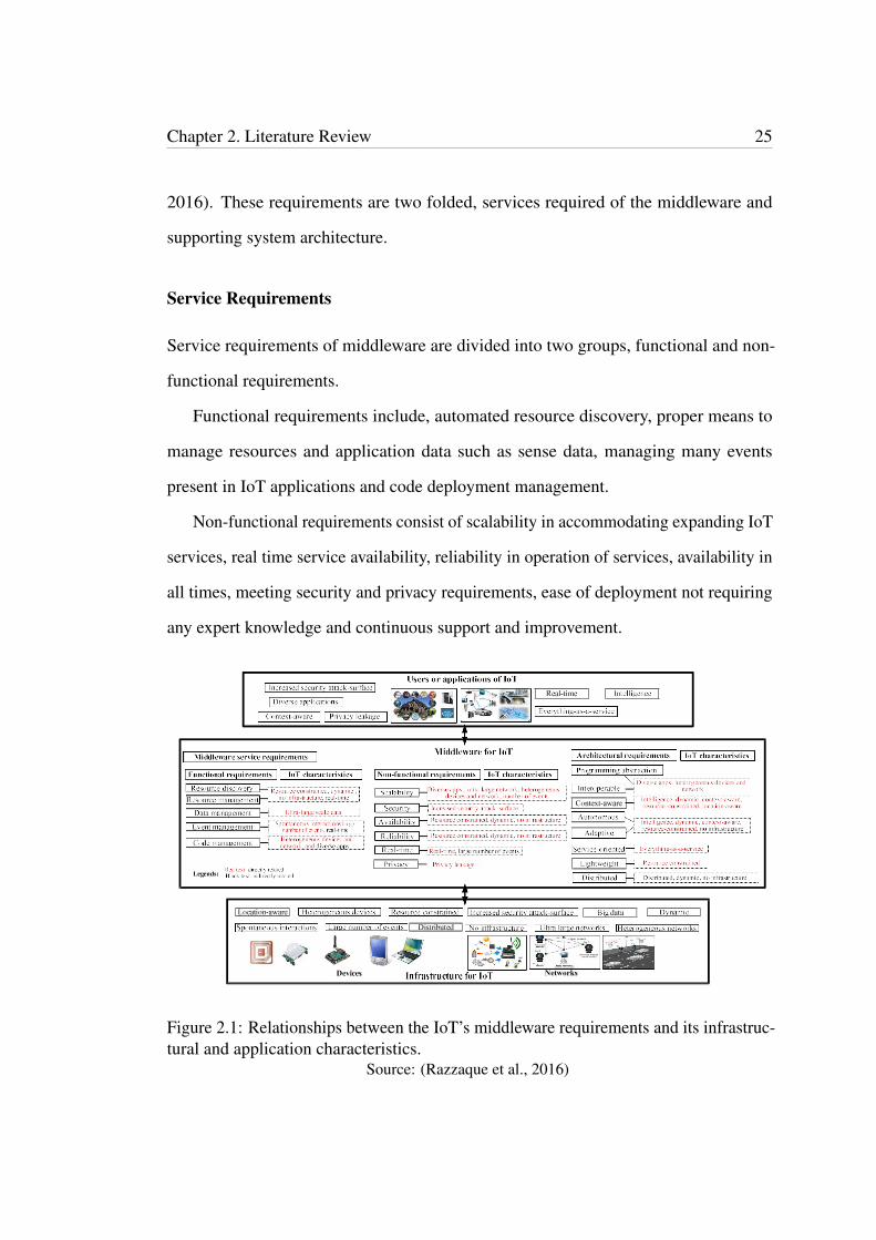
2016). These requirements are two folded, services required of the middleware and
supporting system architecture.
Service Requirements
Service requirements of middleware are divided into two groups, functional and non-
functional requirements.
Functional requirements include, automated resource discovery, proper means to
manage resources and application data such as sense data, managing many events
present in IoT applications and code deployment management.
Non-functional requirements consist of scalability in accommodating expanding IoT
services, real time service availability, reliability in operation of services, availability in
all times, meeting security and privacy requirements, ease of deployment not requiring
any expert knowledge and continuous support and improvement.
Figure 2.1: Relationships between the IoT’s middleware requirements and its infrastruc-tural and application characteristics.
Source: (Razzaque et al., 2016)
Chapter 2. Literature Review 26
Architectural Requirements
Architectural requirements aim for application development. These include program-
ming abstractions needed for application development e.g. interface level separation
from the code, ease of interoperability of various IoT devices and applications, service
based architecture providing enough flexibility, adaptability to dynamic environments,
context aware architecture, autonomous devices, applications and technology interaction
with no direct user support and lastly, distributed architecture to support geographic-
ally distributed resources. As illustrated in the Figure 2.1, many IoT middleware
requirements identified have some direct relationship with IoT characteristics.
Middleware Frameworks for IoT
There are some existing middleware proposals by past researchers. Based on the
design approach they follow, they may be categorised into different groups, such as
event based, service oriented, VM based, agent based, tuple spaces, database oriented
and application specific (Razzaque et al., 2016). Apart from these, there are hybrid
approaches combining different design approaches.
Event Based Middleware
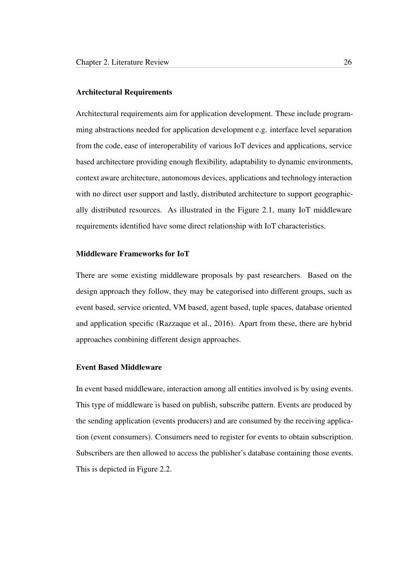
In event based middleware, interaction among all entities involved is by using events.
This type of middleware is based on publish, subscribe pattern. Events are produced by
the sending application (events producers) and are consumed by the receiving applica-
tion (event consumers). Consumers need to register for events to obtain subscription.
Subscribers are then allowed to access the publisher’s database containing those events.
This is depicted in Figure 2.2.
Chapter 2. Literature Review 27
Figure 2.2: Design model for event based middleware.Source: (Razzaque et al., 2016)
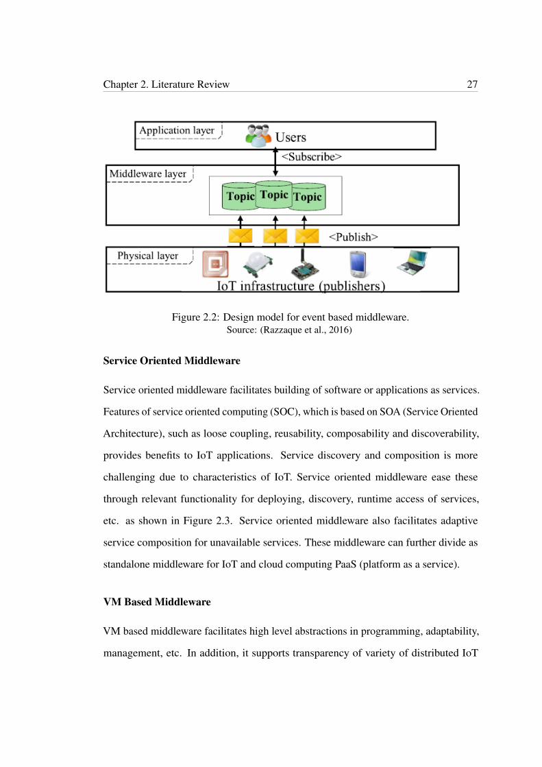
Service Oriented Middleware
Service oriented middleware facilitates building of software or applications as services.
Features of service oriented computing (SOC), which is based on SOA (Service Oriented
Architecture), such as loose coupling, reusability, composability and discoverability,
provides benefits to IoT applications. Service discovery and composition is more
challenging due to characteristics of IoT. Service oriented middleware ease these
through relevant functionality for deploying, discovery, runtime access of services,
etc. as shown in Figure 2.3. Service oriented middleware also facilitates adaptive
service composition for unavailable services. These middleware can further divide as
standalone middleware for IoT and cloud computing PaaS (platform as a service).
VM Based Middleware
VM based middleware facilitates high level abstractions in programming, adaptability,
management, etc. In addition, it supports transparency of variety of distributed IoT
Chapter 2. Literature Review 28
Figure 2.3: Design model for service oriented middleware.Source: (Razzaque et al., 2016)
infrastructure. This middleware is designed to support safe application execution en-
vironment. Applications consist of range of modules, which are distributed through
the network. Network nodes contain VMs interpreting the modules. VMs can be cat-
egorised as two types, middleware level and system level VMs. Middleware level VMs,
which connect the operating system and the applications layer provide functionality
such as concurrency to the OS. System level VMs, which act as substitutes for the OS
or replacing it, make resources available for consumption.
Agent Based Middleware
In agent based middleware, applications are separated into modules to provide the
distribution via networks by using mobile agents. The agents while transferring between
nodes maintain the execution states. This feature provides the decentralised design
facilitating some fault tolerance. These software agents can communicate with each
other for data collection and any updates required for applications.
Chapter 2. Literature Review 29
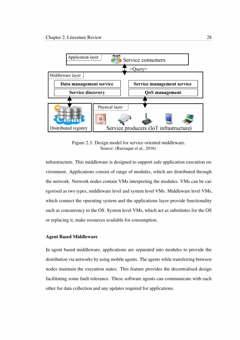
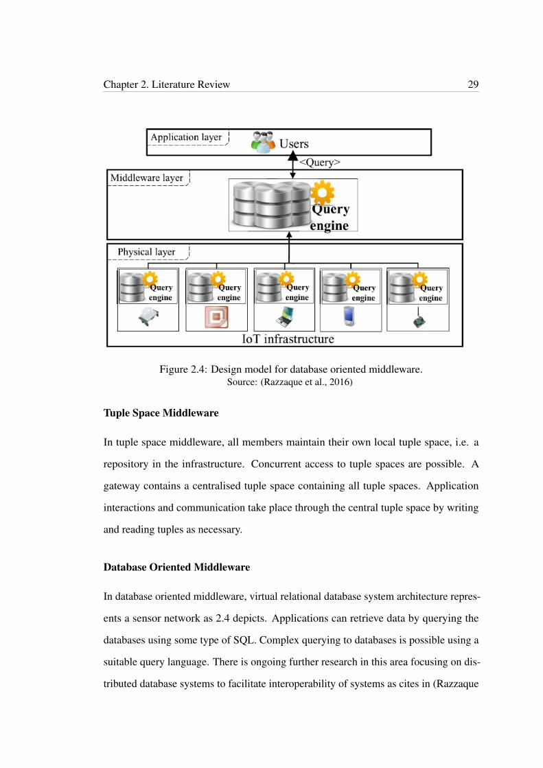
Figure 2.4: Design model for database oriented middleware.Source: (Razzaque et al., 2016)
Tuple Space Middleware
In tuple space middleware, all members maintain their own local tuple space, i.e. a
repository in the infrastructure. Concurrent access to tuple spaces are possible. A
gateway contains a centralised tuple space containing all tuple spaces. Application
interactions and communication take place through the central tuple space by writing
and reading tuples as necessary.
Database Oriented Middleware
In database oriented middleware, virtual relational database system architecture repres-
ents a sensor network as 2.4 depicts. Applications can retrieve data by querying the
databases using some type of SQL. Complex querying to databases is possible using a
suitable query language. There is ongoing further research in this area focusing on dis-
tributed database systems to facilitate interoperability of systems as cites in (Razzaque
Chapter 2. Literature Review 30
et al., 2016).
Application Specific Middleware
In application specific middleware much importance is given to resource management
for applications. This is achieved through an architecture that attends the requirements
of the application domain by improving the network infrastructure.
2.3 Business Process Modelling (BPM)
Among other reasons, the main reason to model a process is to understand the process
clearly by the people who model it and to make other people who are involved in the
process (process participants) understand it the same way. This knowledge gained
through process modelling is the initial step forward in conducting process analysis,
process redesign and process automation. Further, process modelling highlights issues
so that they can be prevented. In general, a model consists of three characteristics, i.e.
mapping, abstraction and suitability for purpose. The model should be able to map
for what it represents. For example, a building to construct should be able to map for
its miniature model made in timber. A model only illustrates the relevant details of
the object it represents, abstracting irrelevant details. When taken timber model as
an example the model abstracts other materials of the building. The model needs to
serve the purpose it was created for. In timber model example, the model illustrates
the building’s appearance when it will be built and this serves the purpose. Similarly,
when it comes to business process modelling, the purpose of creating the model and the
audience it targets for is vital. Business process modelling mainly serves two purposes,
organizational design, and application system design. Modelling for organizational
design is mainly for communication and knowledge but also serves benchmarking and
improvement. These models are targeted for process owners, managers, and business
Chapter 2. Literature Review 31
analysts. Normally, these models are abstracted from features such as IT related aspects
in order to be comprehended by different stakeholders. Business process models
created for application system design are for automation purposes usually containing
implementation details for creating BPMS or carry out software development. These
models are IT based and systems engineers and developers create these models (Dumas,
La Rosa, Mendling, Reijers et al., 2013).
2.3.1 History of Business Process Modelling
Many people have proposed techniques for process modelling in the past century. For
example, Carl Adam Petri (1926 - 2010) in 1962 introduced Petri nets. Petri nets has a
considerable impact on process modelling due to its graphical representation ability of
the process and for its concurrent event representation feature. In business processes,
many events can take place at the same time so that concurrency is a fundamental
feature in a business process model. Petri nets is the first model, which is capable of
modelling concurrency. Many BPM notations adopt Petri nets token system in their
modelling notations.
The importance of data modelling began in the seventies, for example, the Rela-
tional Model introduced by Edgar F. Codd in 1969 and the Entity Relationship Model
introduced by Peter Chen (published in 1976). In the beginning, information systems
were developed by programming from scratch, including data storage and management.
Later database management systems were used for storing and handling data, and
tools automatically generated user interfaces. Business process management (BPM)
systems are similar to this trend even though process management is a more diverse and
complexed task than data management. BPM systems are for process related tasks.
Workflow management (WFM) systems emerged in mid 1990s and its primary
focus was for automating business processes. Business process management can be
Chapter 2. Literature Review 32
considered as an extension of WFM (Van Der Aalst, 2013). However, WFM systems do
not provide much support for functions such as process analysis and management and
are not adequately flexible. Whereas, BPM systems provide better support than WFM
systems for modelling business processes with its features such as support for business
process intelligence, process simulation, case management, etc. In addition, BPM tries
to improve business processes without essentially needing new technologies. Although
BPM utilize software for operational processes, to control and manage them better.
WFM also started with the same purpose in using software but traditional WFM, in
automating the processes has given little attention to management and humans involved
in the business processes.
Process Aware Information Systems (PAISs) comprise of WFM systems and BPM
systems as well as Enterprise Resource Planning (ERP) systems such as SAP, Oracle,
etc., Customer Relationship Management Systems (CRMS), middleware systems such
as WebSphere and other systems like cash handling, call centre management, rule based
systems. Common features to these systems are that the information systems, which
support these systems, are aware of the processes they support and these processes
possess defined notations. Information systems such as database systems and email
systems also can execute some part of a business process though they are not aware
of the processes they are executing. Therefore, these software systems are not process
aware systems.
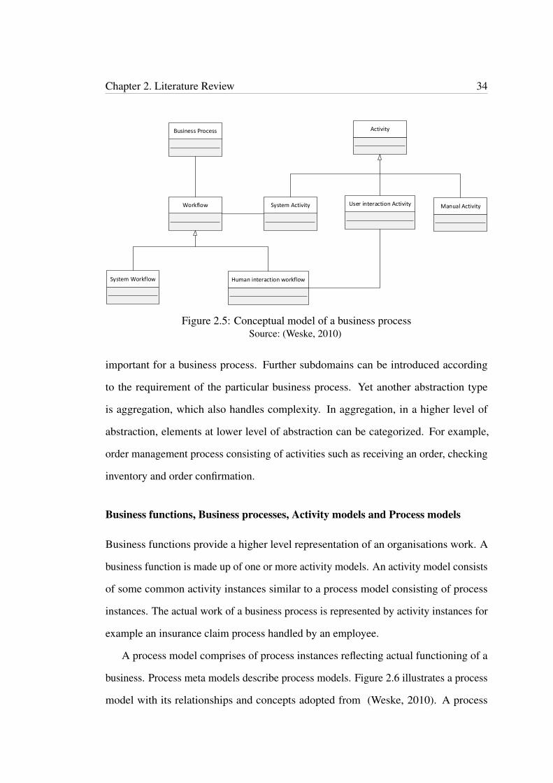
2.3.2 Business Process Modelling
Business process models represents business processes. Business process modelling is
based on conceptual models. These models are usually depicted in UML. Figure 2.5
illustrates a conceptual model of a business process adopted from (Weske, 2010).
Business processes comprise of some activities, which contribute towards achieving
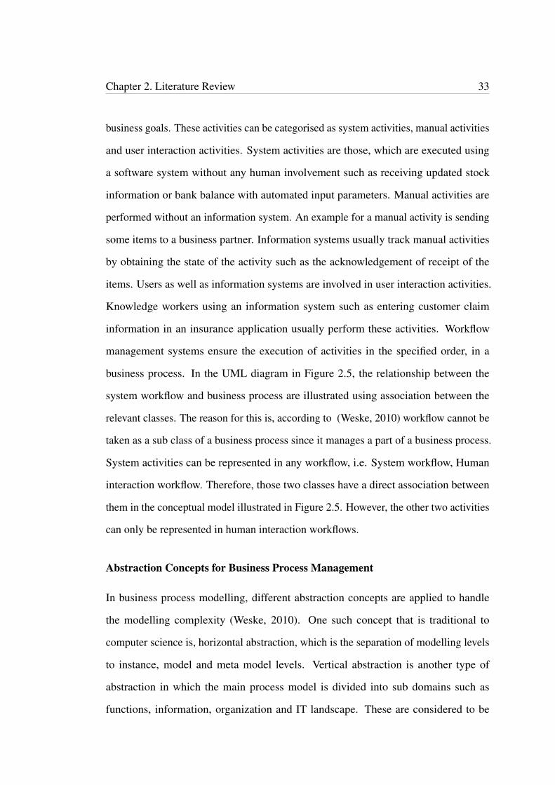
Chapter 2. Literature Review 33
business goals. These activities can be categorised as system activities, manual activities
and user interaction activities. System activities are those, which are executed using
a software system without any human involvement such as receiving updated stock
information or bank balance with automated input parameters. Manual activities are
performed without an information system. An example for a manual activity is sending
some items to a business partner. Information systems usually track manual activities
by obtaining the state of the activity such as the acknowledgement of receipt of the
items. Users as well as information systems are involved in user interaction activities.
Knowledge workers using an information system such as entering customer claim
information in an insurance application usually perform these activities. Workflow
management systems ensure the execution of activities in the specified order, in a
business process. In the UML diagram in Figure 2.5, the relationship between the
system workflow and business process are illustrated using association between the
relevant classes. The reason for this is, according to (Weske, 2010) workflow cannot be
taken as a sub class of a business process since it manages a part of a business process.
System activities can be represented in any workflow, i.e. System workflow, Human
interaction workflow. Therefore, those two classes have a direct association between
them in the conceptual model illustrated in Figure 2.5. However, the other two activities
can only be represented in human interaction workflows.
Abstraction Concepts for Business Process Management
In business process modelling, different abstraction concepts are applied to handle
the modelling complexity (Weske, 2010). One such concept that is traditional to
computer science is, horizontal abstraction, which is the separation of modelling levels
to instance, model and meta model levels. Vertical abstraction is another type of
abstraction in which the main process model is divided into sub domains such as
functions, information, organization and IT landscape. These are considered to be
Chapter 2. Literature Review 34
Business Process Activity
Workflow System Activity User interaction Activity Manual Activity
System Workflow Human interaction workflow
Figure 2.5: Conceptual model of a business processSource: (Weske, 2010)
important for a business process. Further subdomains can be introduced according
to the requirement of the particular business process. Yet another abstraction type
is aggregation, which also handles complexity. In aggregation, in a higher level of
abstraction, elements at lower level of abstraction can be categorized. For example,
order management process consisting of activities such as receiving an order, checking
inventory and order confirmation.
Business functions, Business processes, Activity models and Process models
Business functions provide a higher level representation of an organisations work. A
business function is made up of one or more activity models. An activity model consists
of some common activity instances similar to a process model consisting of process
instances. The actual work of a business process is represented by activity instances for
example an insurance claim process handled by an employee.
A process model comprises of process instances reflecting actual functioning of a
business. Process meta models describe process models. Figure 2.6 illustrates a process
model with its relationships and concepts adopted from (Weske, 2010). A process

Chapter 2. Literature Review 35
Pocess Model
Node Edge
Activity Model Event Model Gateway Model
1
2..* 1..*
2 1..*
Figure 2.6: Business process metamodelSource: (Weske, 2010)
model consists of nodes and edges. Edges represents the control flow of nodes and the
nodes represent activity models, event models and gateway models.
Business Process Execution Architecture
Business process management systems control the execution of a business process using
a business process model. Business process management systems architecture model
consists of the ‘business process environment, a business process modelling sub system,
a business process model repository, a process engine and a set of service providers. The
business process modelling subsystem creates business process models. It generates the
structure of the business process with activities, operations, etc. The business process
environment triggers the initialisation and execution of the process instances of the
process model. Business process model repository stores the created business process
models. The process engine initializes and controls business process execution. This is
Chapter 2. Literature Review 36
the main component of a business process management system and business process
environment triggers this component. Service providers in this architecture model
provides hosting facilities for applications of business process activities.
Process Orchestrations and Process Choreographies
Process orchestrations describe the business process models containing activities and
relationships performed within a single business organization. In process orchestra-
tions, the process engine controls the processes acting as a centralized agent. In most
cases, businesses collaborate with other businesses carrying out their activities making
interaction among process orchestrations generally through passing messages. Pro-
cess choreographies facilitate to realise these interactions among business to business
collaborations.
2.3.3 Business Process Modelling Languages (BPMLs)
Main forces affecting changes in the business processes are improvements in computing
and communication technologies. Business processes are becoming more and more
complex with cross-organisational business processes and are mainly relying on inform-
ation systems. Therefore, it is of great importance for organisations to have process
modelling techniques to manage their business processes providing visibility into to the
flow of processes and documenting them.
For business process management, the process-modelling notation is very important.
There are number of modelling notations in existence, for example, BPMN, UML,
Petri nets and EPCs. A feature common to all these notations are that a process can be
described in activities and possibly in sub processes. In (List & Korherr, 2006), they
identify these process-modelling notations as business process modelling languages
(BPMLs). Examples of BPMLs are:
Chapter 2. Literature Review 37
UML 2.0 Activity Diagram (AD)
AD started with development of software systems and, is for representing business
processes and their flows in software systems. The main features of this modelling
language is actions and, swim lanes representing roles participating in the process.
Business Process Definition Meta model (BPDM)
This is a product of OMG (Object Management Group). The purpose of BPDM is to
provide a meta model for business processes to support mapping of various tools and
languages. BPDM does not have its own graphical natation but uses UML 2.0.
Business Process Model and Notation (BPMN)
BPMN is developed by BPMI (Business Process Management Initiative) and, main-
tained by OMG (Object Management Group) since the two companies merged (WIKIDEDIA,
2017). BPMN is a graphical notation to represent business processes graphically in
business process models. BPMN can be taken as the standard business process model-
ling notation for business process modelling (Wang, Ding, Dong & Ren, 2006). BPMN
provides the organisations to represent their business procedures graphically and stand-
ardised communication of these business procedures. This graphical notation further
facilitates organizations to understand their business collaborations among external
participants. This allows businesses to quickly adjust to changing circumstances of
their internal business procedures and procedures among external business to business
participants (OMG, 2017). Events, activities and sequence flows or arcs are the three
basic concepts of BPMN (Dumas et al., 2013). The basic symbols of BPMN are events,
activities, gateways and connectors.
BPMN includes the aspects of other modelling languages such as graph based and
petri net based process modelling languages, activity diagrams, UML and event driven

Chapter 2. Literature Review 38
process chains. BPMN supports all abstraction levels in an organization ranging from
business levels to technical levels. Business process models are depicted in business
process diagrams. Business process diagrams consist of modelling elements, set of core
elements and complete elements. Core element set is simple and easy to understand
which facilitates expressing simple business processes whereas, the complete element
set provides additional power in elaborating business processes. There are certain rules
set by the BPMN standard that governs these elements when using them. There is no
restriction on BPMN when using a language to express something in the graph, simple
English is possible depending on the situation. However, at technical level, a suitable
programming language is required for translating the model for execution.
According to the BPMN standard, there are five basic categories of BPMN elements,
flow objects, data, connecting objects, swim lanes and artifacts. Events, activities and
gateways are the flow objects defining the behaviour of a business process. BPMN
‘events’ denote the states of real word occurrences related to business processes. Activit-
ies represent work carried out during a business process. Gateways illustrate the control
flow of split and join behaviour between activities, events and gateways. BPMN pool
element represents a participant such as a business partner in a business process. A
pool consists of swim lanes. Lanes denotes organizational aspects such as a department
within an organization.
BPMN elements under ‘Artifacts’ category represent additional information of
business processes which, according to the BPMN standard are not directly associated
with the sequence flow or message flow of a business process. Elements belonging to
the artifact category are data objects, data stores, groups and text annotations. A data
object mainly represents a process documentation, such as a paper and an electronic
object. Text annotations document some business process part in textural form.
There are four main connecting elements, sequence flow, message flow, associations
and data associations. Connecting elements connect other elements such as flow

Chapter 2. Literature Review 39
elements, swim lanes and artifacts.
Event Driven Process Chain (EPC)
This notation was designed aiming business people to understand and manage business
processes easier. EPC comprises of functions and events where functions handle
business process activities and events are results of processing of functions or events
created by actors external to the model. This is an important and rather an informal
notation for modelling domain aspects of a business process (Weske, 2010). Rather
than technical details or formal aspects, the focus of this notation is on domain concepts
and processes.
This was developed as a part of ARIS (Architecture of Integrated Information Sys-
tems) framework as a modelling approach by August-Wilhelm Scheer. This approach is
generally known as ARIS house consisting of a roof and three pillars. The roof denotes
the entire organisation while the three pillars stand for data, control and functions. Each
section (pillar) consists of three levels of abstractions namely, concept level, architec-
ture level and implementation level corresponding to requirements definition, design
specification and implementation description respectively. Data, control and functions
are modelled in the concept level, which being the highest level of abstraction. This
level considers non-technical requirements of business processes such as business goals.
At concept level, ERDs (Entity Relationship Diagrams) are used to model and express
the data view. In the control view, business processes are modelled and expressed
by using EPCs. In the organisational view, organisational structures are described by
organisational diagrams. The architecture level bridges the gap between the concept
level and the implementation level. The implementation level brings the necessary steps
to realise business processes.

Chapter 2. Literature Review 40
Integrated DEFinition Method 3 (IDEF3)
IDEF3 was developed to serve two purposes, the process schematics, i.e. to model
a process sequence, and object schematics, i.e. to model an object and to represent
state changes in a process. This captures how a process behaves explicitly describing
a process. IDEF3 facilitates different views of organisational procedures. IDEF3 has
two modes of modelling, i.e. process flow description (PFD) and object state transition
description (OSTD). PFD describes actual work situation of a business whereas, OSTD
describes permitted transitions of an object in a process (Aguilar-Saven, 2004).
Petri Nets
This notation is developed for modelling dynamic systems with concurrent and non-
deterministic processes. These are used to workflow modelling. This graphical notation
consists of two main nodes, place and transition. Different states of a system is rep-
resented by places and events or actions (caused by state changes) are represented by
transitions.
Carl Adam Petri in his PhD thesis introduced Petri nets (Weske, 2010). Petri nets
are capable of modelling dynamic systems with a static structure. Petri net illustrates the
static structure whereas, the tokens placed in the nets represents the dynamic behaviour
of the system. Circles in the graph represents places, rectangles represent transitions and
directed arcs represents the connections. Tokens represents the dynamic and concurrent
nature of petri nets. Tokens change their positions according to firing rules while
the petri net structure is fixed. Petri net is very suitable for systems that are with
characteristics such as concurrent, asynchronous distributed, parallel, nondeterministic
or stochastic (Wang et al., 2006). Petri nets as graphical tools are similar to flow charts,
block diagrams and networks.
Chapter 2. Literature Review 41
Role Activity Diagram (RAD)
This notation started as coordination modelling and evolved to business process mod-
elling. This represents external events, roles, activities and interactions. RAD is a
graphically based process modelling language emphasising on individual roles and their
relationships. These roles can be organisational functions, software systems, customers
or suppliers (Aguilar-Saven, 2004).
BPMLs have their own execution languages. BPEL, also known as BPEL4WS is
the common execution language for AD, BPDM and BPMN.
2.4 BPMN Modelling Frameworks for IoT
Emergence of information technology in general made a major impact on business
processes. Now, with Internet of Things (IoT) technology, it forces the companies
to revise their business processes to adapt to this new demand. IoT enables process
design through product enhancement by facilitating physical objects to interact and
communicate with each other leading to new service development (Zancul et al., 2016).
Companies can make use of IoT technology in many business segments to achieve
competitive advantage such as product service systems (PSS). According to (Zancul et
al., 2016), IoT market segment consists of three categories:
• Business to Consumer (B2C) – This is the activity of a business trading between
a business and a single buyer (shopify.co.nz, n.d.) In general, retailer transactions
can be included in this category. For example, connected home, connected car,
smart wearable devices, etc.
• Business to Business (B2B) – This refers to a business dealing between two
companies. Most wholesale transactions fall into this category (investopedia.com,
Chapter 2. Literature Review 42
n.d.). For example a business transaction between a manufacturer and a whole-
saler. Examples for B2B IoT applications are, connected industry, connected
buildings, connected agribusiness, etc.
• Business to Business to Consumer (B2B2C) – This model refers to business
transaction connecting business to business and business to consumer. This
is a collaboration process among participants, resulting beneficial channels of
products and service delivery (techopedia.com, n.d.). Examples for IoT applica-
tions based on B2B2C are, smart cities, smart utilities, etc.
From the existing literature, we have chosen to review seven frameworks. These
frameworks propose some IoT modelling elements for business process modelling by
extending BPMN 2.0.
2.4.1 Framework: uBPMN
This framework (Yousfi, de Freitas, Dey & Saidi, 2016) illustrates how to model
systems based on ubiquitous computing (ubicomp) in business processes. Ubiquitous
computing aims to develop systems, which can adopt easily to dynamic business
environments. Context Awareness and Media Breaks are two major aspects of ubicomp.
When a system comes to a halt while processing, a media break occurs requiring
human intervention to proceed. Ubicomp prevents media breaks by automating the
processes so that they are human independent, improving both speed and quality and
less errors. Context awareness improves business processes by taking into account the
contextual environment in which the business operates. It allows business processes
to collect data from the environment and react accordingly. Context for businesses is
any information that is valuable to the business process. Context collection can be done
by using Ubicomp technologies such as location tracking and activity sensing. Google
Now is an example of a ubiquitous system where it responds to user requests by using
Chapter 2. Literature Review 43
ubicomp technologies such as location tracking and activity sensing. This framework
incorporates ubiquitous computing with business process management and define a
ubiquitous business process.
According to the authors, ubiquitous technologies such as sensors and smart readers
cannot not be represented by BPMN v2.0 alone. Therefore, BPMN is extended to
introduce uBPMN model to represent ubiquitous technologies. Authors think this model
is capable of representing all existing ubiquitous technologies to date. The model
introduces three new task elements, Sensor Task, Reader Task and Collector Task by
extending BPMN Task element and Smart Object by extending BPMN Data Input.
All three tasks inherit BMPN Task attributes and smart object inherits the attributes
of BPMN Data Input class. Sensor Task includes smart sensors, wired and wireless
sensors, and sense contextual information in a business environment. The sensor types
can be categorised into temperature, speed, motion, GPS, etc. Similarly, Reader Task is
a task that uses a smart reader, e.g. bar code, RFID, biometrics. Collector Task is a task
that collects any context, which readers and sensors are not capable of collecting. The
source of contextual information collection is a file, a database or another process.
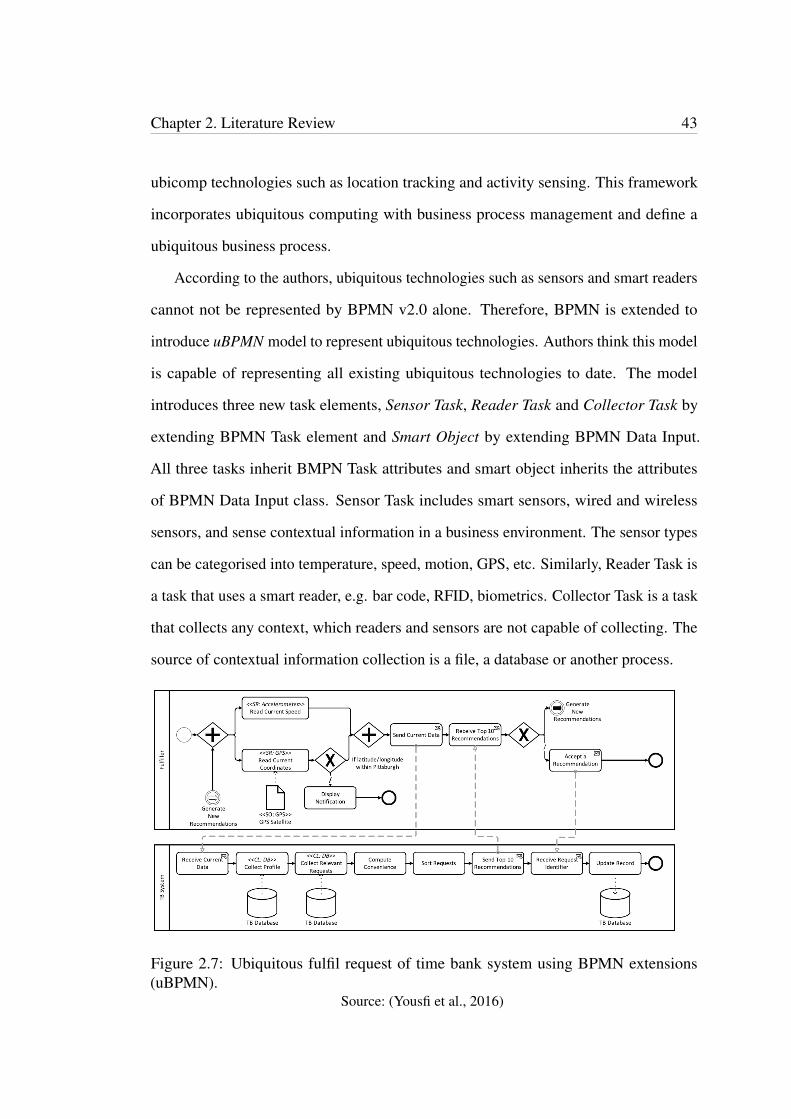
Figure 2.7: Ubiquitous fulfil request of time bank system using BPMN extensions(uBPMN).
Source: (Yousfi et al., 2016)
Chapter 2. Literature Review 44
A case study is carried out to show that Ubiquitous computing can be used as a
technique to improve business processes. A time banking information system, where
a certain community exchanges services is used for this purpose. A user of this
system either can be a requestor of a service or the person who undertakes to fulfil
that service. A requester makes a request for a service via this system for a fee. The
fees are in time dollars. When a service has been fulfilled, these dollars are debited
from requesters account to the service provider’s account. In the case study, Fulfil
Request part of the system is used as a ubiquitous business process as depicted in
Figure 2.7. Ubiquitous business process lists the top ten requests by considering
the potential fulfiller’s contextual information such as his current location, type of
request, time it would take to fulfil the request, nature of the current activity, etc. The
recommendation listings are generated by sensing the fulfiller’s GPS coordinates and
the speed and sending them to the system to compute. The request, need a gallon of
milk is recommended for the potential fulfillers based on their context collected. The
time spent on searching for a matching request is minimised and requests are suggested
on the fly based on the user’s current context. For example, if a user is in a supermarket,
his recommendation list will include a request to buy groceries.
2.4.2 Framework: SPU
This paper (Appel, Kleber, Frischbier, Freudenreich & Buchmann, 2014) introduces
IoT element, event streams to business process management systems. Occurrence of
event streams are real world conditions and business processes can be improved by
incorporating these. For example, monitoring temperature of goods while transporting
them to see if the required temperature is maintained throughout the shipment. The
temperature sensor reading continues throughout and this defines the term stream,
which is continuous occurring of new events. New events are created (event producers)
Chapter 2. Literature Review 45
regardless if they are consumed (event consumers) or not. Due to this independence
nature of events occurring, there needs to be a proper technique to distribute events.
Publish/ Subscribe systems are such a common mechanism.
Though single events are common to business process modelling, there is no proper
mechanism to handle streams of events. Therefore, Event Stream Processing Units
(SPUs) are proposed as an integration concept for event stream processing to integrate
with business processes. SPUs can be considered as equivalent to services in a SOA
(Service Oriented Architecture) since it contains Complex Event Processing (CEP)
functionality. Extensions to model SPUs in Event-driven Process Chains (EPCs) and
a mapping between SPUs in EPCs and SPUs in BPMN to illustrate the application of
the concept are proposed. As BPMN 2.0 modelling extension for SPUs, Event Stream
Processing Tasks (ESPTs) are introduced. The project, Software AG ARIS illustrates the
implementation of the EPC and BPMN extensions.
When implementing a business process, it goes through three stages, the design,
execution and the IT infrastructure. In the design phase, the model is designed using
a technique such EPC or BPMN. The model is executed by using a technique such as
Business Process Execution Language (BPEL). IT support is provided by SOA and
work flow management systems. Unlike SOA services, where services have to be
invoked explicitly, SPUs encapsulate reactive business logic and reacts on streams of
events.
To support SPUs at each layer of the model, Event Stream Processing Services
(ESPSs), ESPTs and Eventlets are introduced respectively at business process modelling,
execution and IT infrastructure layer. Mapping between ESPT and Eventlets takes place
at the execution layer. For SOA, services are the main building blocks whereas, for
an Event Driven Architecture (EDA), SPUs are the main building blocks as shown in
Figure 2.8.
EPC is popular for abstract modelling due to its features. BPMN is more powerful

Chapter 2. Literature Review 46
Figure 2.8: Stream processing units (SPUs) as basic building blocks of an event drivenarchitecture (EDA).
Source: (Appel et al., 2014)
in supporting both abstract and technical process models. Therefore, in Software AG
project, both of them are used. EPC for abstract business models and BPMN for
technical process models. To integrate SPUs with EPC and BPMN, an extension to the
modelling notations is needed to illustrate some features of SPUs as follows:
• Execution semantics: SPUs needs to be stopped after the event completed since
there is no automatic stopping after they started.
• Signalling: This is required for the continuous processing of SPUs.
• Event stream input and output: Event streams are the input for SPUs and output
is specified by the events produced by SPUs.
Event stream modelling can be done by using EPCs functions. An extension to
EPC is required to model SPU in EPC. ESPS to use EPC functions for event stream
processing and, Event Stream Specifications (ESS) to represent input and output in
event streaming are introduced. The Event Stream Processing Unit type represents the
technical part of SPUs.
Chapter 2. Literature Review 47
Order processing example is used to illustrate the application of EPC extension. A
SPU supported by ESPS is used to monitor the environment conditions, i.e. temperature
in a shipment. ESPS initialises an SPU with implicit and explicit completion, which
takes shipment monitoring events as input event screams. Implicit completion ends
when the shipment is completed. Explicit completion is confirmed after the shipment
completion by an additional process step. BPMN is extended to introduce ESSs for
EPCs to show input and output data in event streams, and ESPTs for modelling SPUs.
ESPT’s implicit completion is achieved with a modified conditional sequence flow
whereas, explicit completion is denoted by a dedicated signal. When the process is
completed either explicitly or implicitly, it comes to a stop reflecting a clean shutdown. It
is also possible to model an ESPT with both explicit and implicit completions combined
together.
According to the authors, BPMN events are not suitable for modelling SPUs with
event stream inputs and outputs. Even though BPMN contains task types containing
SPU related features, such as standard service tasks, business rule tasks, loop service
tasks and multiple instance service tasks, SPUs cannot be modelled with those. There-
fore, BPMN is extended for ESPTs. To illustrate the BPMN extension, the shipment
monitoring example already explained is used. In BPMN, ESPT is the shipment monit-
oring SPU. Shipment monitoring SPU receives inputs as streams of monitoring events.
In case of a violation of monitoring conditions, the monitoring SPU sends a message
concurrently indicating the violation, which triggers the exception handling process
with explicit completion. The monitoring ends with a stop signal after the shipment is
over.
For an implicit completion of a shipment, some condition should be matched such
as destination address, which is executed in the SPU. It is possible to model ESPTs with
implicit and explicit completions combined together as well. The default completion is
implicit. However, an explicit completion is triggered if for an instance, the customer
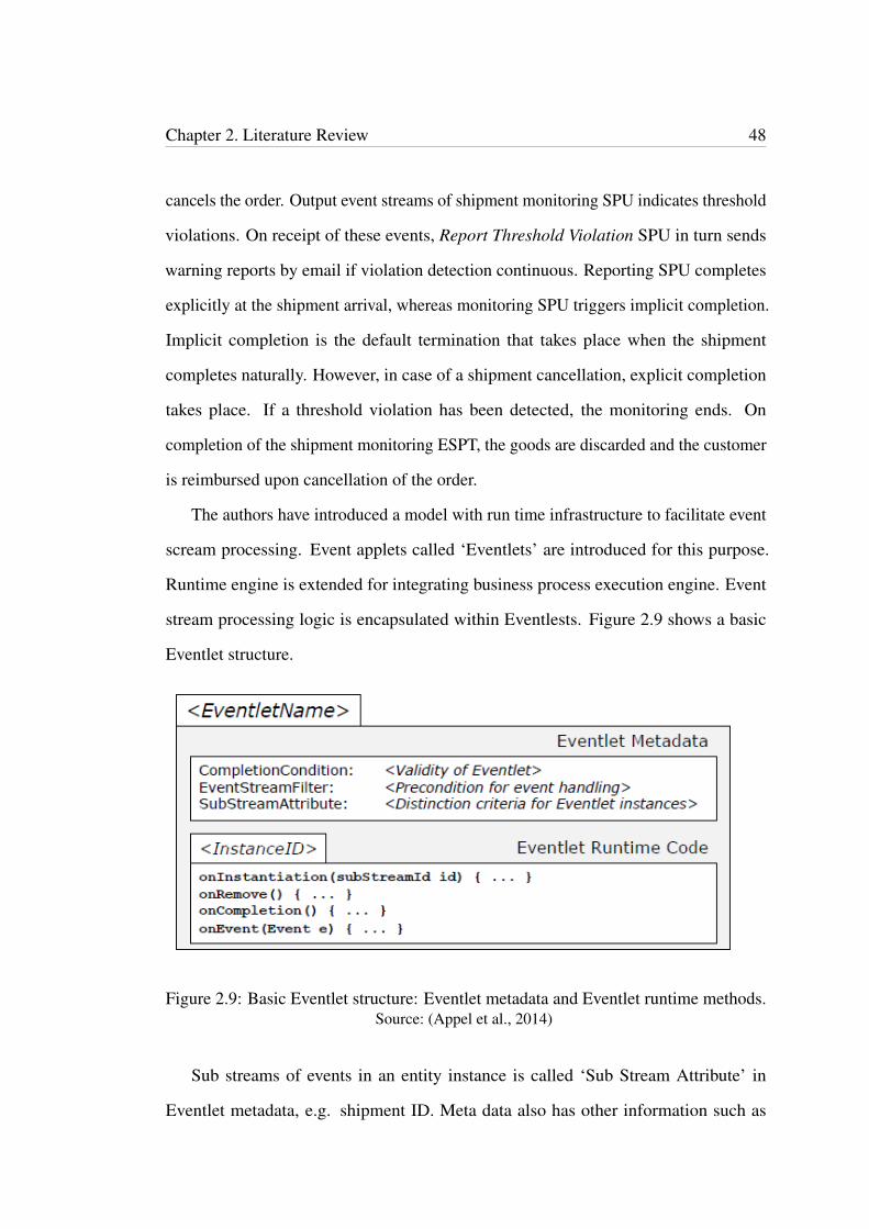
Chapter 2. Literature Review 48
cancels the order. Output event streams of shipment monitoring SPU indicates threshold
violations. On receipt of these events, Report Threshold Violation SPU in turn sends
warning reports by email if violation detection continuous. Reporting SPU completes
explicitly at the shipment arrival, whereas monitoring SPU triggers implicit completion.
Implicit completion is the default termination that takes place when the shipment
completes naturally. However, in case of a shipment cancellation, explicit completion
takes place. If a threshold violation has been detected, the monitoring ends. On
completion of the shipment monitoring ESPT, the goods are discarded and the customer
is reimbursed upon cancellation of the order.
The authors have introduced a model with run time infrastructure to facilitate event
scream processing. Event applets called ‘Eventlets’ are introduced for this purpose.
Runtime engine is extended for integrating business process execution engine. Event
stream processing logic is encapsulated within Eventlests. Figure 2.9 shows a basic
Eventlet structure.
Figure 2.9: Basic Eventlet structure: Eventlet metadata and Eventlet runtime methods.Source: (Appel et al., 2014)
Sub streams of events in an entity instance is called ‘Sub Stream Attribute’ in
Eventlet metadata, e.g. shipment ID. Meta data also has other information such as
Chapter 2. Literature Review 49
‘completion condition’ for an example, ‘time out’. Eventlets can be created either
implicitly or explicitly. For implicit creation, the middleware makes an Eventlet instance
active for each sub stream attribute (e.g. for each shipment). For explicit instantiation,
Eventlets are being created manually by using a fixed sub stream attribute, e.g. a
particular shipment ID. Eventlet completion is specified implicitly by some condition
or explicitly by a command. In the shipment monitoring example, Eventlets detects
temperature violations. This is achieved by querying a database (at instantiation) and
retrieving temperature information for a certain shipment. Complex event processing
(CEP) queries can also be used for temperature violation detection. Authors state that
Eventlets can process couple of thousand events for a second.
In the case of implicit instantiation, an ‘Eventlet Monitor’ is being created by
the middleware. Eventlet instances are created as and when the events of new entity
instances take place. E.g. ‘new shipment’. Eventlets are identified as ’EsptName’ and
are stored in a repository. Java Message Service (JMS) is used for events distribution
by Eventlet middleware. JMS is capable of handling publish/ subscribe communication.
The model handles attribute value events and XML representation. To facilitate ESPT
execution, the Eventlet middleware is extended. As shown in Figure 2.10, a ‘Command
Bus’ connects and controls the Eventlet middleware and is programed as JMS queries.
‘Eventlet Manager’ has a web service interface, which is a Java Enterprise application.
Thesoftware AG’s ARIS is used as a platform for SPU modelling for EPCs and
BPMN. “ARIS is a business process platform for business process analysis, enterprise
architecture, and governance, risk and compliance.” ARIS supports modelling of pro-
cesses with EPCs and BPMN. The model uses ARIS Design Server 9.0 and the ARIS
Architect 9.0 for SPU modelling in EPCs and BPMN. New notations and connection
attributes for SPU modelling in EPCs and BPMN are introduced. ARIS server is
designed as a central repository for process models and process model components.
Automated execution of business process models is an objective of business process
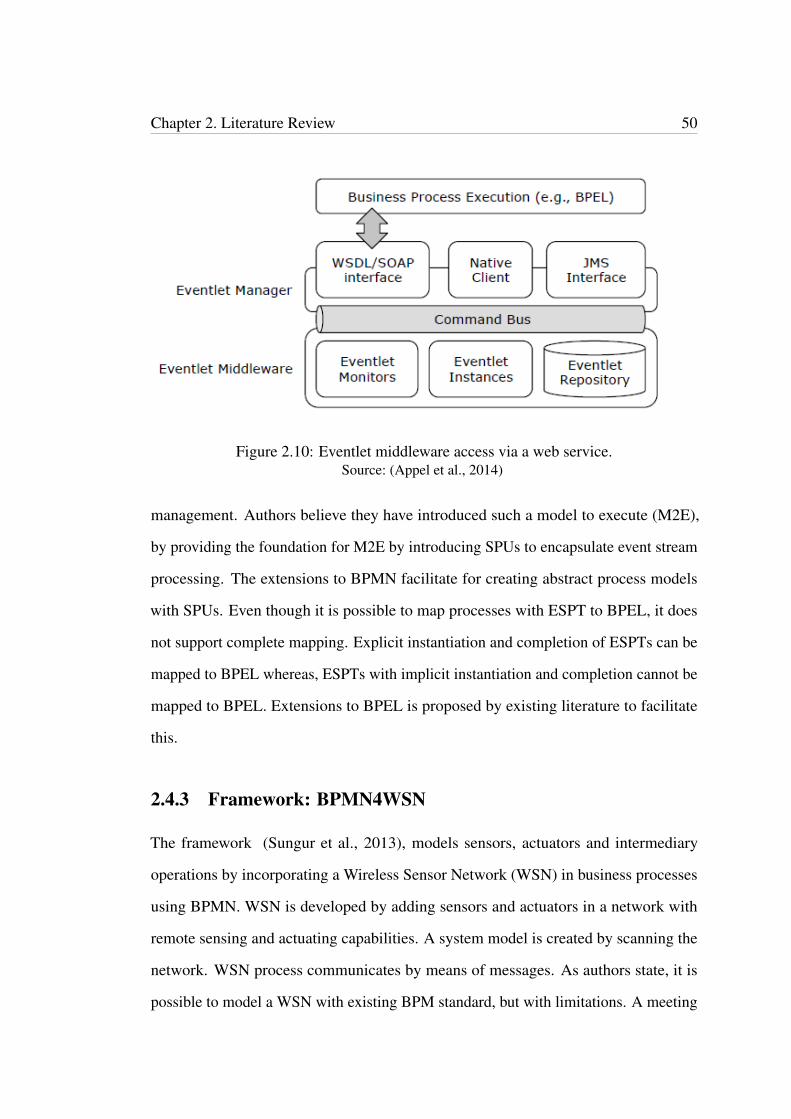
Chapter 2. Literature Review 50
Figure 2.10: Eventlet middleware access via a web service.Source: (Appel et al., 2014)
management. Authors believe they have introduced such a model to execute (M2E),
by providing the foundation for M2E by introducing SPUs to encapsulate event stream
processing. The extensions to BPMN facilitate for creating abstract process models
with SPUs. Even though it is possible to map processes with ESPT to BPEL, it does
not support complete mapping. Explicit instantiation and completion of ESPTs can be
mapped to BPEL whereas, ESPTs with implicit instantiation and completion cannot be
mapped to BPEL. Extensions to BPEL is proposed by existing literature to facilitate
this.
2.4.3 Framework: BPMN4WSN
The framework (Sungur et al., 2013), models sensors, actuators and intermediary
operations by incorporating a Wireless Sensor Network (WSN) in business processes
using BPMN. WSN is developed by adding sensors and actuators in a network with
remote sensing and actuating capabilities. A system model is created by scanning the
network. WSN process communicates by means of messages. As authors state, it is
possible to model a WSN with existing BPM standard, but with limitations. A meeting
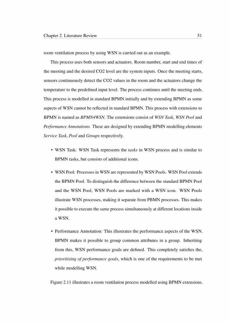
Chapter 2. Literature Review 51
room ventilation process by using WSN is carried out as an example.
This process uses both sensors and actuators. Room number, start and end times of
the meeting and the desired CO2 level are the system inputs. Once the meeting starts,
sensors continuously detect the CO2 values in the room and the actuators change the
temperature to the predefined input level. The process continues until the meeting ends.
This process is modelled in standard BPMN initially and by extending BPMN as some
aspects of WSN cannot be reflected in standard BPMN. This process with extensions to
BPMN is named as BPMN4WSN. The extensions consist of WSN Task, WSN Pool and
Performance Annotations. These are designed by extending BPMN modelling elements
Service Task, Pool and Groups respectively.
• WSN Task: WSN Task represents the tasks in WSN process and is similar to
BPMN tasks, but consists of additional icons.
• WSN Pool: Processes in WSN are represented by WSN Pools. WSN Pool extends
the BPMN Pool. To distinguish the difference between the standard BPMN Pool
and the WSN Pool, WSN Pools are marked with a WSN icon. WSN Pools
illustrate WSN processes, making it separate from PBMN processes. This makes
it possible to execute the same process simultaneously at different locations inside
a WSN.
• Performance Annotation: This illustrates the performance aspects of the WSN.
BPMN makes it possible to group common attributes in a group. Inheriting
from this, WSN performance goals are defined. This completely satisfies the,
prioritising of performance goals, which is one of the requirements to be met
while modelling WSN.
Figure 2.11 illustrates a room ventilation process modelled using BPMN extensions.
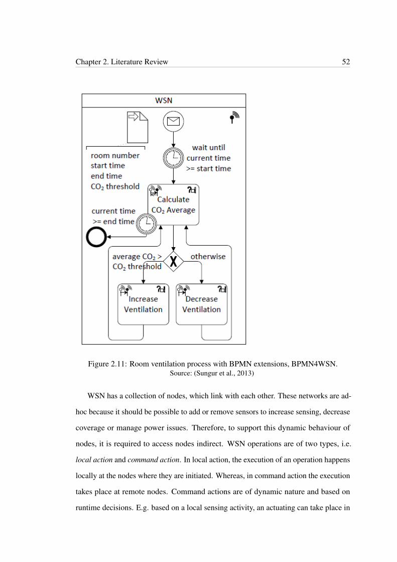
Chapter 2. Literature Review 52
Figure 2.11: Room ventilation process with BPMN extensions, BPMN4WSN.Source: (Sungur et al., 2013)
WSN has a collection of nodes, which link with each other. These networks are ad-
hoc because it should be possible to add or remove sensors to increase sensing, decrease
coverage or manage power issues. Therefore, to support this dynamic behaviour of
nodes, it is required to access nodes indirect. WSN operations are of two types, i.e.
local action and command action. In local action, the execution of an operation happens
locally at the nodes where they are initiated. Whereas, in command action the execution
takes place at remote nodes. Command actions are of dynamic nature and based on
runtime decisions. E.g. based on a local sensing activity, an actuating can take place in
Chapter 2. Literature Review 53
a remote node by a command. Local action and command action both comes under one
of the categories, sense, actuate or intermediary operation. E.g. sense operation sense
the environment for temperature, and based on the output data, the actuate operation
increase or decrease the temperature. The intermediary operation compares the sensed
value with desired level of temperature and takes the decision to increase or decrease
the temperature.
For these operations, 6-tuples are introduced. They are actionType, isCommandAc-
tion, actionPerformer, outputTarget, targetOperation, and returnOperation. A WSN
application can run on different locations at the same time by using different instances
of the same process. An example would be an air-conditioning system with WSN
covering multiple rooms. WSN application execution is distributed among nodes than
in a single node. This eliminates power failures and reduce power usage. Therefore, it
is required to distinguish the particular node, which execute the WSN process. WSN
nodes are subject to failures due to availability of limited resources such as battery
failures. To overcome these limitations, this application specific behaviour should be
taken into account when modelling BPMN.
WSN consists of event driven operations as well as periodic operations. Event
driven operations take place based on an event’s occurring (consuming lesser power)
whereas, periodic operations happen at a set time. E.g. checking if a door is open. For
example, in the event of opening a closed door, this information is communicated in
an event driven operation. Thus, in periodic operation, it checks if the door is opened
periodically even when it is closed. It should be possible to illustrate both these two
types of operations in a BPMN model. It should also be flexible to make minor changes
to WSN without affecting the model’s stability.
Drawbacks of using standard BPMN for modelling WSN and the benefits of using
BPMN4WSN with BPMN extensions are demonstrated by comparing against each
Chapter 2. Literature Review 54
requirement of WSN. In the extended model, Support for Indirect and Dynamic Ad-
dressing of Nodes is made possible by defining expressions which allows direct, indirect,
static and dynamic access of nodes whereas, in BPMN, only pool names can be used
as attributes to access nodes. Applying extensions, Support and Restrict User to WSN
Operation Categories is fully supported while BPMN has no support for sense, actuate
and intermediary operations. Support for Multiple Instances of the Same Process is
achieved by using tasks in a pool with extensions, whereas standard BPMN processes
are reflected by pools. In BPMN, there is no facility to achieve Distribution of Execution
Logic into WSN, however with extensions; this is possible by using orchestrationPer-
former of WSN Task. Standard BPMN does not support Prioritization of Performance
Goals, while with extensions this is achieved by applying parameters to each task and
also by adding performance goals at run time. Support for Event-driven Actions in
Modelling is achieved through extensions though standard BPMN does not distinguish
between event-driven and periodic tasks. The requirement, Models should be stable
on minor WSN changes is achieved by extended BPMN, although in standard BPMN
changes to WSN can only be accomplished by addition or removable of pools.
2.4.4 Framework: Things of IoT in BPMN
This framework (Meyer et al., 2015) models physical entity or the thing of IoT in a
business process by extending BPMN. A reference model (IoT domain model) defines
the main IoT components that can be mapped with BPMN elements. This model is
referred to as guidance for this work. According to IoT reference model, it should
be possible to transfer the main components of IoT meta-model to a BPMN specific
meta-model to incorporate IoT based modelling into business processes. According this
model, the main building blocks of IoT are:
• The device e.g. temperature sensor, which connects the physical world with

Chapter 2. Literature Review 55
digital word.
• The thing e.g. chocolate, which is a part of the physical environment.
• The native service e.g. sensing and actuating abilities, via which the connection
is established.
• The IoT Service e.g software components for connection.
The example used for modelling IoT elements with business processes is “ A Web
service shall measure the temperature of the physical entity chocolate by means of one
currently available device that is accessible via the Internet”. Three elements of BPMN
Meta model, which are suitable for modelling physical entity in business processes
are identified. They are, Text Annotation, Data Object and Participant. In modelling
physical entity the focus is on two main aspects, i.e. the process modeller’s ability
for graphical representation and machine readable output. While these are the main
requirements, the other requirements include, the physical entity cannot belong to a
message flow or a sequence flow, should not connect to any data association or process
element and inability to assign to any pool or lane.
Text Annotation is a subclass of Artifact.Artifacts in the BPMN standard which
facilitates presenting more information and available at machine-readable model. This is
process related without any effect on the message flow. However, this is not suitable for
representing physical entity. Therefore, in parallel to Text Annotation, a Custom Artifact
class is created by extending the class Artifact. This also come with the disadvantage
that it is assignable to a pool. Data Object is a subclass of ItemAwareElement and is
related to process execution, which is not a feature of the physical entity. Therefore, a
custom Item aware element to represent the physical entity is introduced. Participant
class, which is a subclass of BaseElement in the BPMN standard, is not suitable for
representing the physical entity because it is possible to represent it in a pool and can
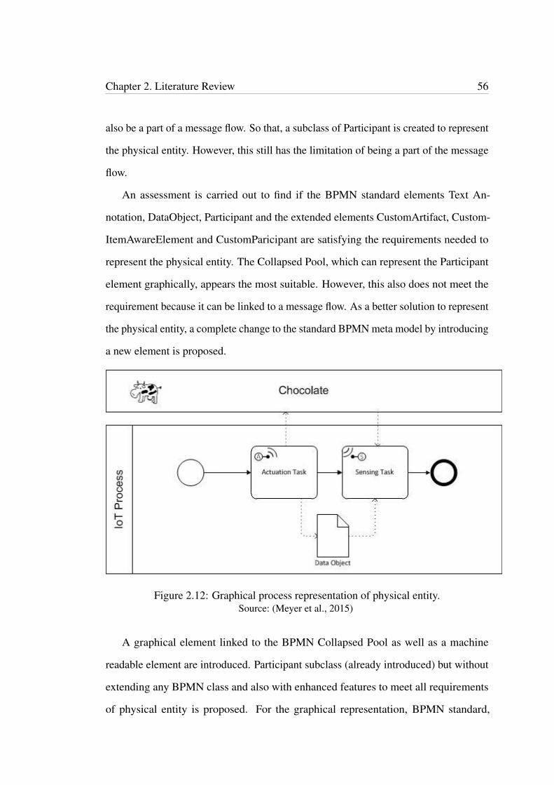
Chapter 2. Literature Review 56
also be a part of a message flow. So that, a subclass of Participant is created to represent
the physical entity. However, this still has the limitation of being a part of the message
flow.
An assessment is carried out to find if the BPMN standard elements Text An-
notation, DataObject, Participant and the extended elements CustomArtifact, Custom-
ItemAwareElement and CustomParicipant are satisfying the requirements needed to
represent the physical entity. The Collapsed Pool, which can represent the Participant
element graphically, appears the most suitable. However, this also does not meet the
requirement because it can be linked to a message flow. As a better solution to represent
the physical entity, a complete change to the standard BPMN meta model by introducing
a new element is proposed.
Figure 2.12: Graphical process representation of physical entity.Source: (Meyer et al., 2015)
A graphical element linked to the BPMN Collapsed Pool as well as a machine
readable element are introduced. Participant subclass (already introduced) but without
extending any BPMN class and also with enhanced features to meet all requirements
of physical entity is proposed. For the graphical representation, BPMN standard,
Chapter 2. Literature Review 57
Collapsed Pool is extended to represent the element Participant. Machine-readable
model is created without confirming to the BPMN standard. This new extension satisfies
the remaining requirement of not being a part of a message flow so that all requirements
needed for representing physical entity are achieved.
Figure 2.12 illustrates the graphical process model, where two separate pools are
used to represent the two participants, physical entity and the IoT process. The item
chocolate denotes the physical entity and the cow symbolises that anything can be taken
as a physical entity.
2.4.5 Framework: Crowdsourcing
This paper (Tranquillini, Daniel, Kucherbaev & Casati, 2015) introduces micro-task
crowdsourcing processes, to BPMN. Crowdsourcing is a way of outsourcing work to
many people (a crowd), on a crowdsourcing platform such as Amazon Mechanical Turk
or CrowdFlower often for a reward in return. These are called crowdsourcing processes,
which comprise of multiple tasks, actors and operations. These micro-tasks can be
completed in parallel making it faster and efficient.
A scenario of reimbursing travel expenses of company employees is taken as an
example in illustrating crowd sourcing processes. The receipts are scanned and uploaded
to an online crowdsourcing platform. A request is sent out for offers to transcribe them
one by one. For each two transcriptions, in another task, the crowd request the workers
to check for their accuracy and to fix if there are any mistakes. A worker needs to handle
two items together at a time since this process takes lesser time. Yet in another task,
the transcribed receipts are categorized into their relevant types such as hotel, flight,
food, etc. A worker handles four transcriptions together since this is even simpler. After
transcription, parallel execution of these two tasks are possible. Upon completion of
this process the admin is notified by an automatic email.
Chapter 2. Literature Review 58
BPMN does not fully support modelling crowdsourcing processes to achieve the
maximum benefits it offers. BPMN model consists of two main constructs, tasks and
control flow connectors. Tasks are automatic, consist with start and end events. Multi
instance tasks, which also have start and end events can execute in either parallel or
sequence. However, the end event occurs only when all instances finished executing.
For crowdsourcing this behaviour of the BPMN tasks is not suitable since multiple tasks
instances needs to be executed in parallel without waiting for an end event. An example
would be to upload a set of images and to label them. These two tasks should run in
parallel. However, with BPMN tasks, the labelling only starts after the image uploading
ends. Therefore, to model crowdsourcing processes, the authors propose an extension
to BPMN.
Authors propose an extension to BPMN by introducing two new elements, crowd
task and a streaming connector. A crowd task consists of some micro tasks collectively
performed by a crowd of people on a crowdsourcing platform. Parallelization benefits
are achieved through streaming the finished micro tasks, while other instances of the
particular crowd task are still executing. Streaming connector supports screaming data
grouping, splitting and multiplication and the data transfer between the process and
crowd tasks. Data screaming is achieved through middleware between BPMN and the
crowdsourcing platform. This monitors micro task end processes and grouping, splitting
and multiplying of completed micro task instances. When these task instances end, the
monitor sends a message to the process engine so that it can start with the next micro
task. Two crowd tasks are connected by streaming connector and they can connect
single or multiple times at run time depending on the data transformation function.
Streaming data transformation function can be of many types, flat, group, split or
multiply. Flat indicates streaming without any data transformation. Group implies to
stream in groups. Split defines to stream as they are without any data transformation
and to separate the output into the elements they were before. Multiply is similar to split
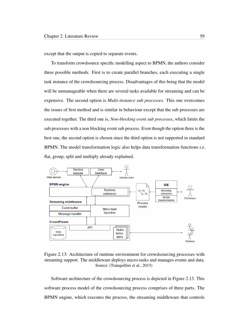
Chapter 2. Literature Review 59
except that the output is copied to separate events.
To transform crowdsource specific modelling aspect to BPMN, the authors consider
three possible methods. First is to create parallel branches, each executing a single
task instance of the crowdsourcing process. Disadvantages of this being that the model
will be unmanageable when there are several tasks available for streaming and can be
expensive. The second option is Multi-instance sub processes. This one overcomes
the issues of first method and is similar in behaviour except that the sub processes are
executed together. The third one is, Non-blocking event sub processes, which limits the
sub processes with a non blocking event sub process. Even though the option three is the
best one, the second option is chosen since the third option is not supported in standard
BPMN. The model transformation logic also helps data transformation functions i.e.
flat, group, split and multiply already explained.
Figure 2.13: Architecture of runtime environment for crowdsourcing processes withstreaming support. The middleware deploys micro-tasks and manages events and data.
Source: (Tranquillini et al., 2015)
Software architecture of the crowdsourcing process is depicted in Figure 2.13. This
software process model of the crowdsourcing process comprises of three parts. The
BPMN engine, which executes the process, the streaming middleware that controls
Chapter 2. Literature Review 60
the events and data transformation, the crowdsourcing platform, Crowdflower, which
handles the micro-task instances. After transforming the process model into an execut-
able model, it is deployed in the BPMN engine. Business process engine executes both
human tasks and machine tasks, while crowdsourcing platform executes the crowd tasks.
User interface design is handled inside the crowdsourcing platform. The platform also
enables programming access via APIs.
The extensions to BPMN model are implemented in a case study. Three templates to
use in Crowdflower are created. These templates accept input data and outputs the results
needed by the processes. The process evaluated by testing three times with streaming
and another three times without streaming by uploading forty receipts manually. This
highlighted the streaming benefits. With streaming, within ten minutes, 90 percent
of receipts of all three crowd tasks are completed whereas, only transcription level is
completed without streaming. Moreover, with streaming the first receipt completes all
three tasks in a couple of minutes while without streaming it takes about one hour and
30 minutes to complete the first receipt.
However, with screaming it takes more time to complete all of the receipts when
all receipts without streaming gets completed faster. According to existing research,
the reason for this being the users in a crowdsourcing platform tend to select first
two pages of micro tasks. This can be considered as a disadvantage. Furthermore,
for some last micro task instances, the final stage is not completed specially for the
receipts with streaming. In addition, there are some disadvantage to the implementation.
Sub processes cannot be introduced at run time so that at design time this should be
accommodated for. It is possible to divide streaming connectors into branches although
it is not possible to re-connect them. Only BPMN related processes can be controlled
whereas, how tasks are handled inside the crowdsourcing platform is beyond control.
Therefore, for example, the instances when a few micro tasks not completed is not
controlled. These disadvantages should be insignificant compared to the advantages of
Chapter 2. Literature Review 61
crowdsourcing.
2.4.6 Framework: Event Element for IoT
Authors in this paper (Chiu & Wang, 2015) state that BPMN events can represent IoT
aspects better though many researchers focus on BPMN elements other than events
when extending BPMN 2.0 for business process modelling for IoT. Majority of the
work is based on extending BPMN elements activity, pool or lane, artifact, etc. This
work extends BPMN element event for business process modelling for IoT.
According to BPMN 2.0 definition, an event is something that takes place during
a process lifecycle usually triggering an action or result. This behaviour of events are
closely related to IoT applications but traditional BPMN 2.0 events are not adequate
enough for representing IoT related processes. Characteristics of IoT are evaluated for
the purpose of finding out the requirements for extending BPMN element, event.
As event either triggers something or results something, most IoT based scenarios
represent characteristics of events. For example, when air conditioning a room, once
all conditions become true for starting the air conditioner, the process will start and an
actuator turns on the air conditioner. Two types of IoT architectures are considered for
the modelling example of events. ‘Cloud centric IoT’ where all IoT elements such as
sensors, actuators and services are connected to each other in the cloud by providing a
web service interface to internet. The second architecture is an ‘IoT gateway’ based, in
which, sensors and actuators register to the IoT gateway initially and communicate with
each other afterwards. The authors in theit modelling example uses the IoT gateway
based architecture.
Nine BPMN event element extension requirements are identified through eight
weaknesses in BPMN lacking support for business process modelling for IoT.
• Entity based concept – process modelling should adhere with entity based concept.
Chapter 2. Literature Review 62
In a simple IoT aware process for an air-conditioning a room, the start event
triggers simply when the room temperature is at a certain predefined value but as
the process continuous, the sensors monitor the room temperature. Therefore, at
design phase, some entity will define the start event and at run time, the control
will pass to sensors.
• Distributed execution – processes should be capable of distributing their execution
among many devices. IoT based processes can run on multiple gateways with
collaboration among them. In an IoT application of air conditioning a room, the
room is located at gateway 1 and the air conditioner is controlled by gateway 2
making the two gateways communicate with each other.
• Interactions – IoT aware business processes introduce two more interactions,
device interactions and service interactions. For example, temperature is detected
by a temperature sensor or obtaining average temperature by a web service.
• Distributed data – IoT applications may distribute data over many data storages.
For example, temperature sensors located in a room and to obtain the average of
all, the data should be collected from all sensors concurrently.
• Scalability – sensors and actuators in an IoT application may increase or de-
crease for some reason such as due to a failure in the device, requiring a control
mechanism to handle these situations.
• Availability/ mobility – In IoT applications, sensors, actuators and physical
objects should be able to move freely. For an example, the process of temperature
detecting by sensors start only when a person move into the room.
• Fault tolerance – a business process heavily relies on availability of devices,
services and the communication technology. In an IoT application, device availab-
ility is not always certain. Faults can occur due to two reasons, unstable networks
Chapter 2. Literature Review 63
and faults of devices such as sensors and actuators. This makes two requirements,
fault tolerance of network crashing and faulty devices.
• Quality of information – Quality levels of the information provided by the devices
and services to business processes should be in certain levels of accuracy. In an
IoT application, required accuracy level of information differs, depending on the
context.
BPMN conditional event, message event and error event are extended to represent
three new events and a new event to represent location is introduced. The event definition
is also extended to facilitate the above identified requirements, entity concept, fault
tolerance and quality of information.
BPMN conditional start event extension is considered more suitable for representing
situations of IoT related processes such as collecting data from devices or physical
entities (i.e. temperature at a certain value), status of a device or physical entity such as
fault in a sensor and total number of devices or physical entities, for example number of
cars exceeding a certain level in a car park.
The BPMN message event is extended to explain the interactions among process
engines better. Two main interaction types are catch and throw, i.e. receiving a message
from a process and sending a message to another process. For example in an IoT
scenario, a message is passed from one IoT gateway to another when the temperature
is at a certain value to start air conditioning a room. Extension of BPMN error event
facilitates fault tolerance of IoT devices such as the actuator realizing some fault with
an air conditioner while trying to start it and reporting to maintenance staff in a message.
The new event created for location better represents the IoT location awareness feature.
Location event represents situations such as position of a device or a physical entity and
moving of a device or a physical entity. Event definition extension covers the entity
concept, fault tolerance levels and information quality.

Chapter 2. Literature Review 64
Figure 2.14: Completed temperature controlling process model with event extension ofBPMN 2.0.
Source: (Chiu & Wang, 2015)
A sample IoT application models a temperature control process, which uses the
introduced IoT modelling elements. This process starts when there are two start events
that are satisfied, i.e. at least one person in the room and the room temperature is
between a predefined range of values. When the conditions are true, the start event
fires and gateway of the room sends a message to another gateway, which controls
the window closing to request to close the windows. Once the first gateway receives
the confirmation of window closure from the second gateway, the control is passed to
an actuator to turn the air conditioner on. If the air conditioner is faulty, a message
is passed to the maintenance staff for repair. The fans are turned on concurrently by
Chapter 2. Literature Review 65
another actuator task. This process is illustrated in Figure 2.14.
2.4.7 Framework: IoT Devices as Resources
This paper (Meyer, Ruppen & Magerkurth, 2013) addresses integrating IoT devices with
native software components as a new resource type in business processes as no sufficient
attention is given to this area by past researchers. An IoT reference model defines the
main building blocks of IoT. They are the physical entity or thing (e.g. flower), device
(e.g. sensor), native service (e.g. sensing capability provided by the device’s software)
and IoT service (e.g. web service interface). The authors adhere to this in their work.
IoT integration can add value to business solutions such as ERP systems and they try to
integrate IoT with ERP systems. ERP systems are based on planned business processes
with human resources, whereas IoT comprises of vast number of devices as resources
based on web and constantly reacting to dynamic environment and adapting processes
accordingly. As traditional business processes do not provide the facility to model
IoT aware processes directly, this work attempts to integrate IoT devices as resources
in business processes and build an IoT aware business process model. In trying to
represent IoT devices and native services as resources in IoT aware process models,
the authors come up with some contributions. They are, analyse and identifying IoT
domain concepts, illustrate IoT device and software components in a swim lane and a
resource model, integrate a general semantic model, extend the graphical model and
test the graphical model in practice by extending a business process modelling tool.
In introducing the process model, authors propose extensions to BPMN 2.0 notation
to include IoT devices and native software components. There are two challenges.
First, the BPMN specification does not speak about IoT devices or native services.
Second, there are two types of resources, IoT device and its native services, which are at
different levels, are to be dealt with at the same time. BPMN standard does not facilitate
Chapter 2. Literature Review 66
concurrent dealing of different resources at different levels in a process model.
Unlike physical entity, an IoT device is a process performer like a human user who
is a direct participant in the process. The other process resource is the native service or
the software component of the device. In the graphical model, a separate pool represents
IoT Process with one lane for normal processes and another lane containing IoT Device.
IoT Device lane consists of a Sensing Task.
In the BPMN 2.0 machine-readable model, the authors have introduced four new
classes trying to be in consistent with BPMN 2.0 standard, by overcoming the challenges
they faced when positioning them. A new class IoTDevice is introduced as a sub class
by extending the Lane class. Lane is a sub class of BaseElement so that the class,
IoTDevice inherits all attributes and associations of the class BaseElement. The class
ResourceRole is extended introducing a new class named NativeService under the
class Performer to represent the device’s software resources. Since Performer is a
sub class of the class ResourceRole inheriting attributes and model associations of the
parent class, the new class, NativeService inherits all those features as well. Third
new class, IoTParameterDef is introduced in parallel to IoTDevice and this is used for
parameter definitions by IoTDevice class. This class contains two attributes, name and
extParameterRef. The attribute extParameterRef is used for referencing the parameters
since those are not stored in BPMN model. The final new class, IoTAssignment is used
for defining the resource assignment of IoT device and native services. The process
model consists of both graphical and machine-readable aspects and it uses IoT as well
as non IoT process tasks.
The authors carry out an implementation by extending a web based editor tool
to illustrate a modelling example in practice. Figure 2.15 illustrates this process. A
dynamic pricing process of an item in a store is modelled as an example. This application
uses the two extensions to BPMN 2.0, IoT device and native service. This process
is modelled by using a BPMN editor, which was extended to incorporate these IoT
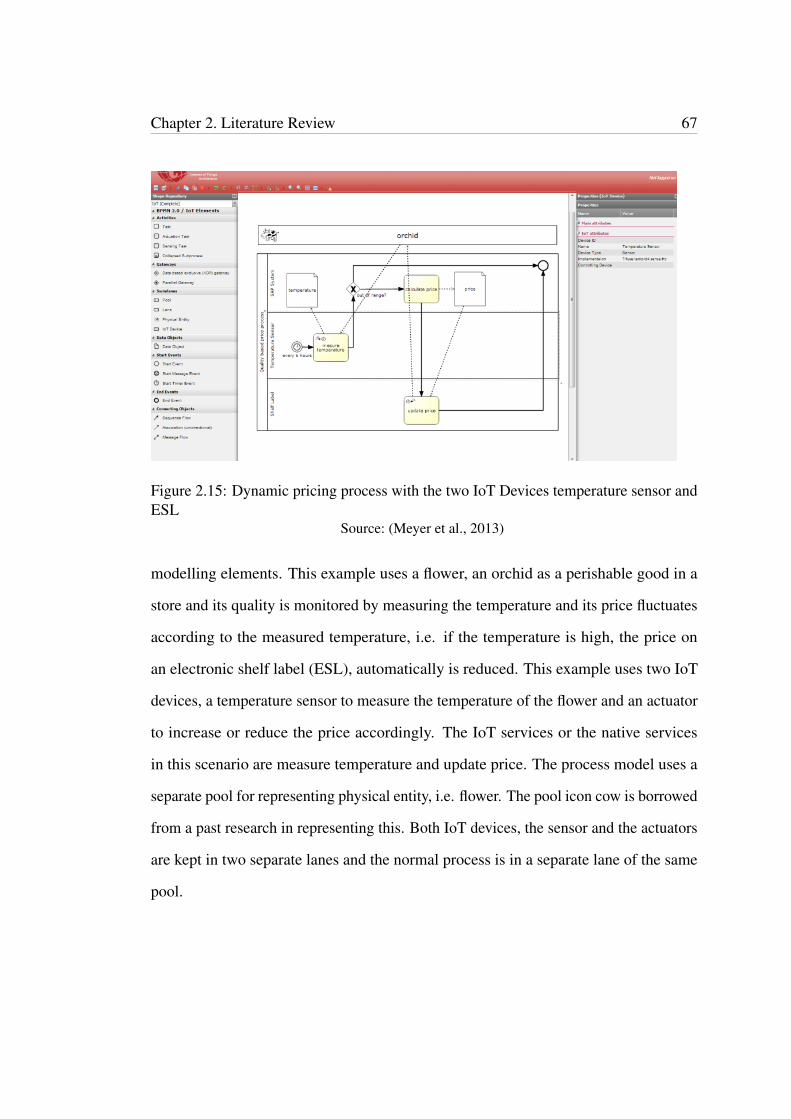
Chapter 2. Literature Review 67
Figure 2.15: Dynamic pricing process with the two IoT Devices temperature sensor andESL
Source: (Meyer et al., 2013)
modelling elements. This example uses a flower, an orchid as a perishable good in a
store and its quality is monitored by measuring the temperature and its price fluctuates
according to the measured temperature, i.e. if the temperature is high, the price on
an electronic shelf label (ESL), automatically is reduced. This example uses two IoT
devices, a temperature sensor to measure the temperature of the flower and an actuator
to increase or reduce the price accordingly. The IoT services or the native services
in this scenario are measure temperature and update price. The process model uses a
separate pool for representing physical entity, i.e. flower. The pool icon cow is borrowed
from a past research in representing this. Both IoT devices, the sensor and the actuators
are kept in two separate lanes and the normal process is in a separate lane of the same
pool.
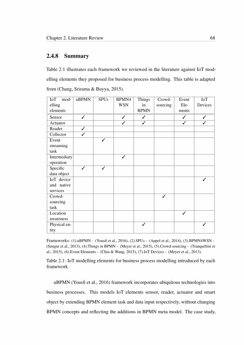
Chapter 2. Literature Review 68
2.4.8 Summary
Table 2.1 illustrates each framework we reviewed in the literature against IoT mod-
elling elements they proposed for business process modelling. This table is adapted
from (Chang, Srirama & Buyya, 2015).
IoT mod-ellingelements
uBPMN SPUs BPMN4WSN
Thingsin
BPMN
Crowd-sourcing
EventEle-
ments
IoTDevices
Sensor 3 3 3 3 3
Actuator 3 3 3 3
Reader 3
Collector 3
Eventstreamingtask
3
Intermediaryoperation
3
Specificdata object
3 3
IoT deviceand nativeservices
3
Crowd-sourcingtask
3
Locationawareness
3
Physical en-tity
3 3
Frameworks: (1).uBPMN - (Yousfi et al., 2016), (2).SPUs - (Appel et al., 2014), (3).BPMN4WSN -(Sungur et al., 2013), (4).Things in BPMN - (Meyer et al., 2015), (5).Crowd-sourcing - (Tranquillini etal., 2015), (6).Event Elements - (Chiu & Wang, 2015), (7).IoT Devices - (Meyer et al., 2013).
Table 2.1: IoT modelling elements for business process modelling introduced by eachframework
uBPMN (Yousfi et al., 2016) framework incorporates ubiquitous technologies into
business processes. This models IoT elements sensor, reader, actuator and smart
object by extending BPMN element task and data input respectively, without changing
BPMN concepts and reflecting the additions in BPMN meta model. The case study,
Chapter 2. Literature Review 69
‘time banking’ application process models the extended BPMN elements, sensor task,
collector task and smart object. The system is deployed both web based and as a mobile
app using the same web services.
The case study covers a scenario where people trade services in favour of money
and tries to demonstrate the advantages of incorporating ubiquitous technologies with
BPMN. The request lists presented to service providers are filtered with most suitable
requests based on his location (context-awareness), time to fulfil request, etc. For an
example, the request for ‘gallon of milk’ is included in the list of request provider who
is already in a supermarket. Carrying out an implementation using the process model
and conducting some tests distinguishes this study. However, the reader task introduced
has not been incorporated in the process model and the implementation tests are limited
to test cases.
Event stream processing in framework SPU (Appel et al., 2014) using event stream
processing units (SPUs) introduces a concept for continuous reading of stream of events
using sensors. The example illustrates how a shipment monitoring SPU, which receives
streams of events as input would measure temperature during shipment to keep it under
threshold limits and signal temperature violations if there are any. The process can
terminate with either explicit completion by a given condition or implicit completion
or the combination of both. In case a violation is detected, the exception handling
process is called which, brings the process to an end explicitly. The customer can cancel
the order with a refund rather than receiving spoiled or damaged goods. This result
in maintaining business reputation and customer satisfaction. The process model is
executed as well. However, the model comes with some technical limitations such as
BPEL presently does not support implicit insanitation and completions of event stream
processing tasks (ESPTs).
Real world interactive situations represented through events are closely related to
IoT. Therefore, this work would immensely benefit in modelling IoT related business
Chapter 2. Literature Review 70
processes.
Moreover, at the execution layer of the business process implementation, the authors
introduce EDA (event driven architecture) for SPUs. This can be considered important
since IoT related business applications being interactive with the environment through
devices such as sensors and reacting to event streams are not well supported by web
services and SOA (Barros et al., 2012). This is due to two reasons. Primary reason
being that the web services are based on request respond mechanism which is pull
based whereas IoT based applications mainly require push based mechanism due to its
reactive nature to occurrence of environmental events, etc. Second reason is that web
services hide the middleware they run on.
BPMN4WSN (Sungur et al., 2013) uses BPMN to integrate sensors and actuators
to a business process model by means of a wireless sensor network. The goal is to
bridge the gap between technical experts who desire to build WSN and the domain
experts who design business processes. The application demonstrates a meeting room
ventilation process with WSN. Upon starting the meeting, the sensors continuously
detect the CO2 levels in the meeting room and reports until the meeting is over. The
actuators adjust the temperature level to a desired level, which was a predetermined
input to the process at start. The process was modelled with standard BPMN and by
extending BPMN illustrating how sensors, actuators and intermediary operations can
be incorporated into BPMN. With extensions, the process became simpler and more
efficient.
However, there is some possibility that this extension to BPMN could result in some
confusion among domain experts. The model comes with some limitations as well.
It is a challenging and a difficult task to create WSN since development requires low
level programming languages. Some extensions to the model, e.g. the way pools are
used in expressing processes can create confusion when understanding standard BPMN
elements. Moreover, BPMN4WSN is not platform independent since the tool can only
Chapter 2. Literature Review 71
generate code for sensors based on the open source operating system for IoT, Contiki
OS. The model is not tested enough in practical environments, though it is to be tested
in areas such as logistics and predictive maintenance in the future.
The framework, Things of IoT in BPMN (Meyer et al., 2015) demonstrates how
the thing of IoT or the physical entity can be better reflected in business processes.
For representing physical entity with BPMN, three elements of BPMN model, text
annotation, data object and participant are selected. When these elements could not
satisfy all identified requirements in representing physical entity, each base class is
extended to create custom classes. A test result indicates that custom participant class
(collapsed pool) as most suitable for representing the physical entity in the standard
BPMN. (This information would become useful for someone who would want to model
physical entity without extending BPMN.)
Since this does not fully satisfy all requirements in representing physical entity, a
fundamental change to the BPMN meta model is proposed. That is a separate graphical
element linked to BPMN collapsed pool and, a machine readable element extending
the participant subclass. In the graphical representation of the physical entity, the
symbol ‘cow’ indicates that the physical entity can be a living being. This proposal is
argumentatively viable except for the extensions are not conforming to BPMN standards
and the consequences could be considerable.
Crowdsourcing (Tranquillini et al., 2015) framework proposes an extension to
BPMN to accommodate crowdsourcing processes. A practical example of receipts
feeding to a crowdsourcing platform demonstrates that streaming crowd tasks are more
efficient than non-streaming tasks. Therefore, BPMN extensions are applied to model
streaming crowd task processes.
Tasks and control flow connectors of standard BPMN is initially considered for
modelling crowdsourcing processes. BPMN tasks has clearly defined start and end
Chapter 2. Literature Review 72
events and facilitate the runtime execution of multi-instance tasks in parallel or sequen-
tial. Crowdsourcing requires task instances to run in parallel. Even though the BPMN
tasks have parallel execution, their end events limits obtaining the streaming benefits
from crowdsourcing because one task has to end for the other to start.
Task instance streaming for micro-task crowdsourcing is a useful technique for
business processes. However, this is platform dependent as it is only tested on open-
source BPM platform, Activiti, and only a few micro tasks are used. The authors intend
to stress test with some thousands of micro tasks and carry out experiments to find out
the reasons for some micro tasks taking a long time to finish.
Authors in Event Element for IoT (Chiu & Wang, 2015) extend BPMN element
event to facilitate business process modelling for IoT. The argument is that events reflect
the characteristics of IoT better. As extensions to BPMN three event elements and
one new modelling element representing location are introduced. The new events are
conditional event, message event and error event. Context awareness is an important
feature in IoT applications, therefore the new location event can be considered as an
important addition. The modelling example uses all BPMN event extensions proposed
as IoT modelling elements. For modelling the sample application process, an actuator
task modelled by existing research was borrowed to use with the event extensions
introduced, making the process more complete.
The framework, IoT Devices as resources (Meyer et al., 2013) proposes two ex-
tensions to BPMN 2.0, IoT device and the native service of IoT reference model. The
extensions are illustrated in both graphical model and machine-readable model. The
example models a sensor and an actuator as an IoT device. Though there is a statement
of ERP system integration, the sample process model is not adequate in illustrating
the IoT application in ERP systems. However, the authors have gone to an extend to
practically implementing the modelling extensions to a BPMN editor, which we have
not come across elsewhere in our literature review. A sensor task and an actuator task
Chapter 2. Literature Review 73
are added to the editor’s toolkit as BPMN extensions. Existing BPMN editors already
provide a pool and lanes and labelling each lane accordingly. The separate pool uses in
representing physical entity contains the icon cow that is borrowed from a past literature
work.
Overall, one common limitation in most works are that the models are not tested
enough to see how their extensions would affect the standard BPMN, and the domain
experts who design the business model. However, it is apparent that all have contributed
in representing IoT modelling elements in business processes one way or the other.
In comparison, we introduce more IoT modelling elements and model them in our
case study example. Moreover, we extend an existing web based BPMN editor to
incorporate all modelling elements we have proposed as extensions to BPMN and an
extra element, physical entity. We demonstrate the capability of our editor by practically
modelling these elements in an IoT related process using this tool. Moreover, this
editor incorporates an XPDL editor and we extend this XPDL editor as well to include
our extensions. We generate XPDL code to store our IoT related business process
model. Only one work (Meyer et al., 2013) has practical extended a BPMN editor tool.
However, the extensions are limited to two new task elements, sensor and actuator and
no specific method of storing and distributing the model, which we do through XPDL
as already mentioned.
2.5 Conclusion
This chapter considered some literature related to business process modelling for IoT
and mainly dedicated to discuss IoT modelling frameworks. We reviewed seven chosen
IoT modelling frameworks, which integrate IoT modelling elements into business
processes. We discussed each work in detail empathising on their contributions for
business process modelling for IoT. Overall, they have identified IoT modelling elements

Chapter 2. Literature Review 74
sensor, actuator, reader, collector, event streaming, intermediary operation, specific
data object, physical entity and, location awareness, crowdsourcing, IoT device and
native service representation in business process models. In the summary section, we
compared each framework with IoT modelling elements introduced by them in a table.
Furthermore, we discussed each work by critically reviewing and highlighting the
contributions.
Chapter 3
Running Scenario and Requirements
Derivation
3.1 Introduction
This section consists of four subsections. In section 3.2, a running problem scenario is
introduced. A part of supply chain management is taken as the problem scenario, mainly
highlighting the inventory part of it. This example can be considered as a typical work
scenario, which is capable of covering the key aspects of IoT modelling elements. The
business process model of the problem scenario is modelled and illustrated in BPMN.
In section 3.3, we identify requirement elicitation of business process modelling
for IoT. We derive business process modelling requirements for IoT using the problem
scenario introduced in the previous sub section. We identify seven new IoT modelling
elements as business process modelling requirements for IoT, which answers our
first research question. We propose UML class diagrams to better illustrate these
requirements with their attributes and relationships. Requirements, which are illustrated
as UML classes, are further broken down into sub classes wherever applicable. As we
have found different groups of characteristics for certain requirements, we categorise
75
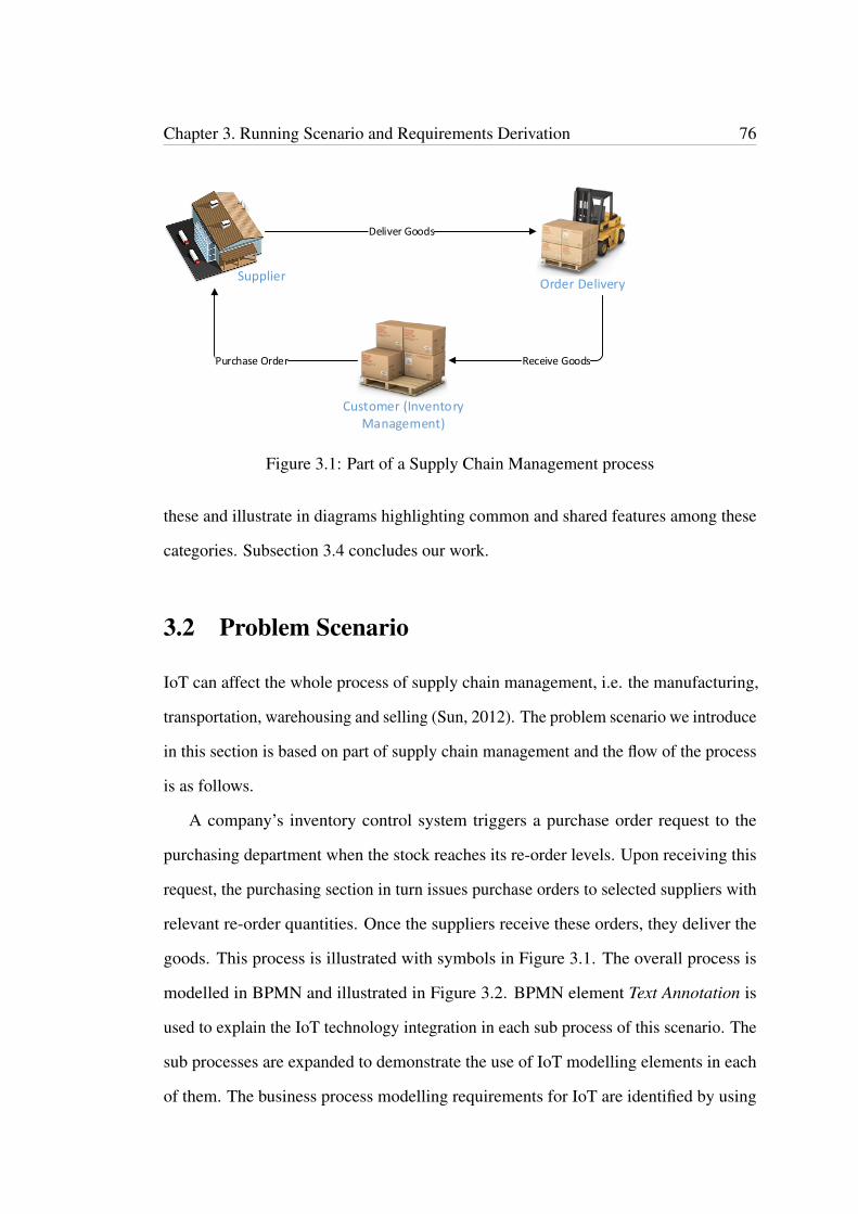
Chapter 3. Running Scenario and Requirements Derivation 76
Deliver Goods
Receive GoodsPurchase Order
SupplierOrder Delivery
Customer (Inventory Management)
Figure 3.1: Part of a Supply Chain Management process
these and illustrate in diagrams highlighting common and shared features among these
categories. Subsection 3.4 concludes our work.
3.2 Problem Scenario
IoT can affect the whole process of supply chain management, i.e. the manufacturing,
transportation, warehousing and selling (Sun, 2012). The problem scenario we introduce
in this section is based on part of supply chain management and the flow of the process
is as follows.
A company’s inventory control system triggers a purchase order request to the
purchasing department when the stock reaches its re-order levels. Upon receiving this
request, the purchasing section in turn issues purchase orders to selected suppliers with
relevant re-order quantities. Once the suppliers receive these orders, they deliver the
goods. This process is illustrated with symbols in Figure 3.1. The overall process is
modelled in BPMN and illustrated in Figure 3.2. BPMN element Text Annotation is
used to explain the IoT technology integration in each sub process of this scenario. The
sub processes are expanded to demonstrate the use of IoT modelling elements in each
of them. The business process modelling requirements for IoT are identified by using
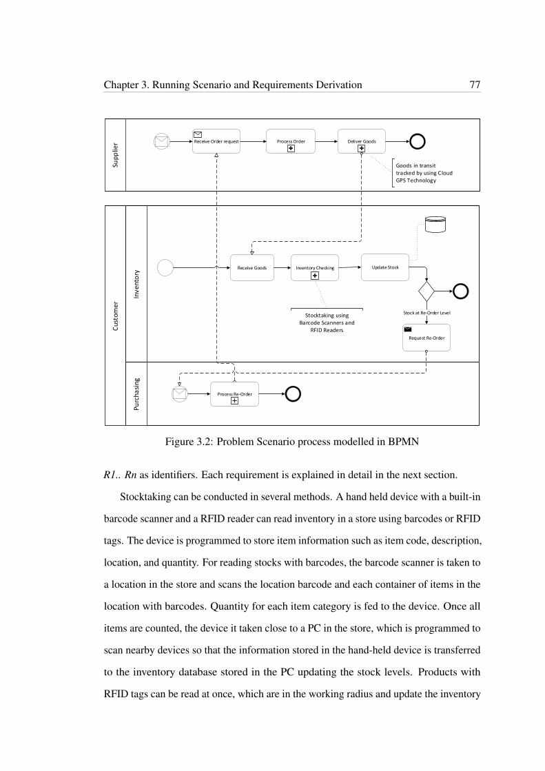
Chapter 3. Running Scenario and Requirements Derivation 77
Cus
tom
er
Purc
hasi
ngIn
ven
tory
Sup
plie
r
Inventory Checking Update Stock
Stock at Re-Order Level
Request Re-Order
Receive Goods
Receive Order request Deliver GoodsProcess Order
Process Re-Order
Stocktaking using Barcode Scanners and
RFID Readers
Goods in transit tracked by using Cloud GPS Technology
Figure 3.2: Problem Scenario process modelled in BPMN
R1.. Rn as identifiers. Each requirement is explained in detail in the next section.
Stocktaking can be conducted in several methods. A hand held device with a built-in
barcode scanner and a RFID reader can read inventory in a store using barcodes or RFID
tags. The device is programmed to store item information such as item code, description,
location, and quantity. For reading stocks with barcodes, the barcode scanner is taken to
a location in the store and scans the location barcode and each container of items in the
location with barcodes. Quantity for each item category is fed to the device. Once all
items are counted, the device it taken close to a PC in the store, which is programmed to
scan nearby devices so that the information stored in the hand-held device is transferred
to the inventory database stored in the PC updating the stock levels. Products with
RFID tags can be read at once, which are in the working radius and update the inventory
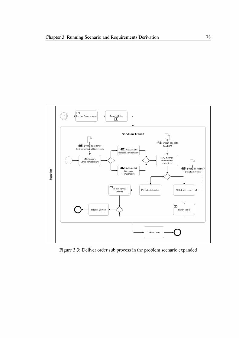
Chapter 3. Running Scenario and Requirements Derivation 78
Supp
lier
Receive Order request
<R1: Sensor> Sense Temperature
<R5: Event screams>Environment condition events
SPU monitor environment
conditions
<R2: Actuator> Decrease
Temperature
<R2: Actuator>
Increase Temperature
<R6: smart object>Cloud GPS
SPU detect issues
<R5: Event screams>Deviation events
SPU detect violations
Report Issues
Inform normal delivery
Prepare Delivery
Deliver Order
Process Order
Goods in Transit
Figure 3.3: Deliver order sub process in the problem scenario expanded
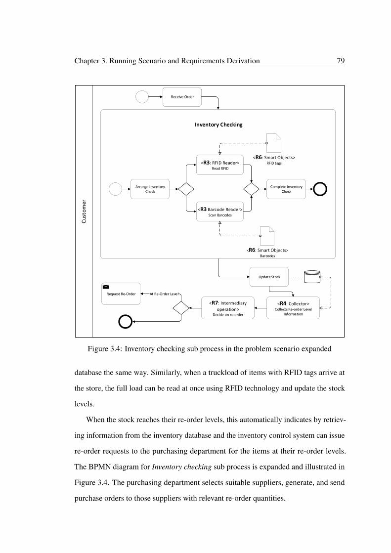
Chapter 3. Running Scenario and Requirements Derivation 79
Cus
tom
er
Arrange Inventory Check
Complete Inventory Check
<R3 Barcode Reader>Scan Barcodes
<R3: RFID Reader>Read RFID
<R6: Smart Objects>
Barcodes
<R6: Smart Objects>RFID tags
Receive Order
Update Stock
<R4: Collector>Collects Re-order Level
Information
Request Re-Order
<R7: Intermediary
operation>Decide on re-order
At Re-Order Level
Inventory Checking
Figure 3.4: Inventory checking sub process in the problem scenario expanded
database the same way. Similarly, when a truckload of items with RFID tags arrive at
the store, the full load can be read at once using RFID technology and update the stock
levels.
When the stock reaches their re-order levels, this automatically indicates by retriev-
ing information from the inventory database and the inventory control system can issue
re-order requests to the purchasing department for the items at their re-order levels.
The BPMN diagram for Inventory checking sub process is expanded and illustrated in
Figure 3.4. The purchasing department selects suitable suppliers, generate, and send
purchase orders to those suppliers with relevant re-order quantities.

Chapter 3. Running Scenario and Requirements Derivation 80
Upon receiving purchase orders from the customer, the supplier in turn will deliver
goods. RFID technology together with Cloud based GPS will track and monitor the
goods in transit for traffic conditions, etc., affecting the transit time. Temperature sensors
will continue to check for environment conditions during the shipment to maintain the
quality of goods in transit. The BPMN diagram for the sub process, Deliver order is
expanded and shown in Figure 3.3.
Once the customer receives the goods, stocktaking as already described, takes place
updating the stock levels in the database.
3.3 Requirements Derivation
In this section, we explain the seven new business process modelling requirements for
IoT identified by using the problem scenario introduced in the previous sub section.
The requirements are linked to the sub processes modelled in BPMN, and illustrated
in Figure 3.3 and Figure 3.4. Each requirement is explained first by introducing the
requirement, followed by its uses in applications and finally, describing in what stages
of the problem scenario it is being used.
In Figure 3.5, class diagram for business process modelling requirements for IoT is
illustrated.
3.3.1 Requirement 1 (R1): Sensor as the Business Process Model-
ling Requirement for IoT
Sensors are popular in IoT systems. Sensors collect context information from the
environment acting as input transducers. (Vladimer, 2015) states that “A sensor
transforms interesting, useful energy into electrical data". Camera and microphone in a
smart phone are examples of simple sensors. Sensors detect events or changes such as
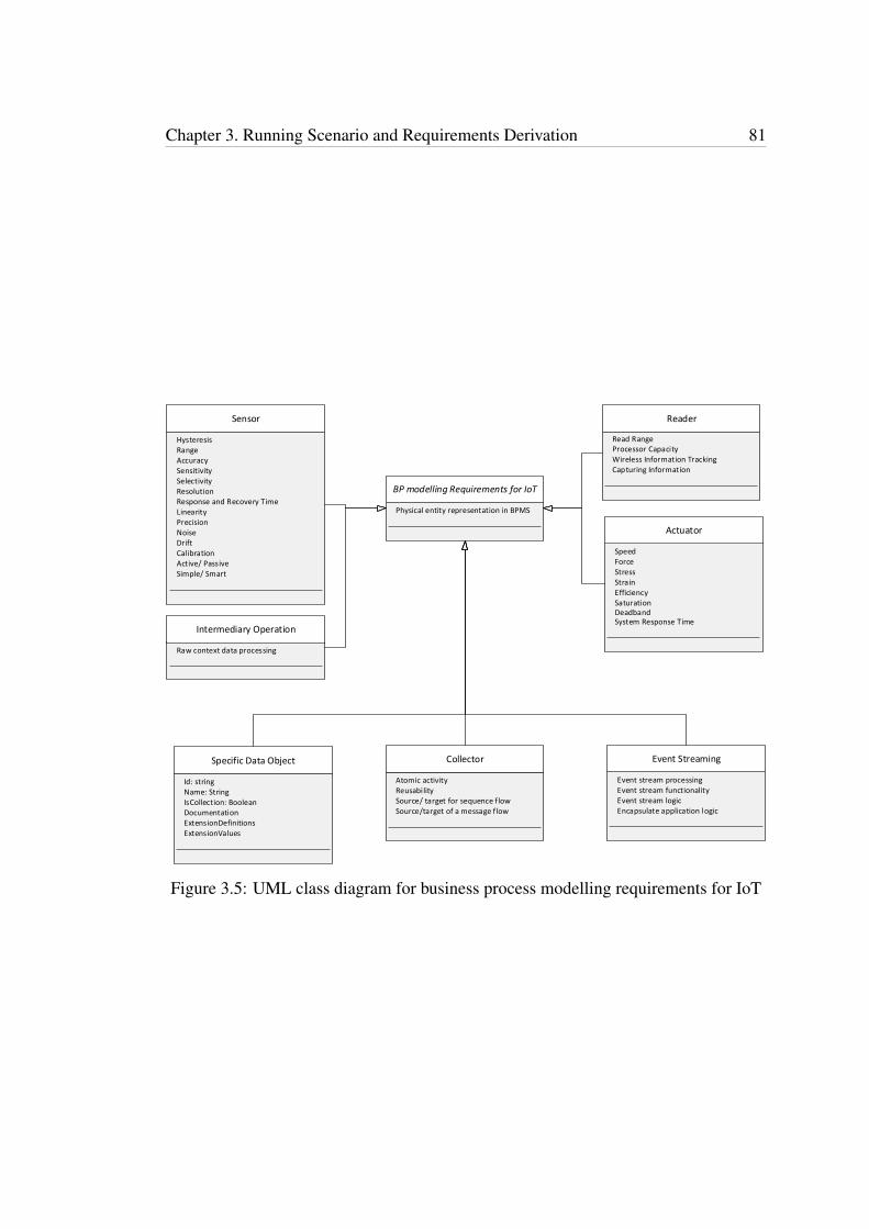
Chapter 3. Running Scenario and Requirements Derivation 81
BP modelling Requirements for IoT
Sensor
Intermediary Operation
Reader
Actuator
Specific Data Object Event Streaming
Event stream processing
Collector
Source/ target for sequence flow
Physical entity representation in BPMS
RangeAccuracySensitivitySelectivity
Response and Recovery TimeResolution
LinearityPrecision
Hysteresis
Calibration
NoiseDrift
Name: String
Active/ PassiveSimple/ Smart
Event stream functionality
Read RangeProcessor CapacityWireless Information TrackingCapturing Information
System Response Time
Speed
SaturationEfficiencyStrainStressForce
Deadband
Id: string
Raw context data processing
IsCollection: BooleanDocumentationExtensionDefinitionsExtensionValues
Reusability
Source/target of a message flow
Atomic activity
Encapsulate application logicEvent stream logic
Figure 3.5: UML class diagram for business process modelling requirements for IoT
Chapter 3. Running Scenario and Requirements Derivation 82
temperature, heat, sound, pressure and motion in the physical environment and provide
relevant outputs. Most of them produce digital, mostly electrical outputs by taking
analog inputs often requiring analog to digital converters. They collect data from any
location at any time and transmit them real-time via IoT networks (Rayes & Samer,
2017).
Sensors can be active and passive. In active sensors, the signals they produce are
reflected back to the sensors themselves, whereas passive sensors react to signals they
receive such as sounds and heat. Example for active sensors are radar, GPS, x-ray and
infrared and passive sensor examples are electric, heat, chemical and photographic
(mpls.com, n.d.).
Sensors can also be categorised as simple or smart. Smart sensors are a type of
sensors and, at their minimum, they comprise of a sensor, microprocessor and some
communication connectivity. They process the inputs they take from their environments
before releasing them as outputs (Rouse, 2015). Smart sensors provide additional
functionality such as filter duplicate data and notify IoT gateway upon meeting specific
conditions, thus needing certain programming logic in the sensors (Rayes & Samer,
2017). Smart sensors are an important part of IoT applications, particularly in business
applications such as supply chain management (O’Donnell, 2017). Among other uses,
these sensors have three main purposes, namely identifying items, locating them and
measuring environment conditions. Sensors of this category detect the status of products
being shipped throughout the shipment process and report any deviation in temperature
or quality via messages. What is more, sensors with help of Cloud GPS services detect
any delays or unexpected incidents in transportation in advance so that prompt decisions
are feasible.
Retailers in their businesses use proximity sensors to trace customer movement
and promote products by sending discount coupons to their phones. In the same way,
sensors have become very useful in transporting goods. In agriculture, sensors such
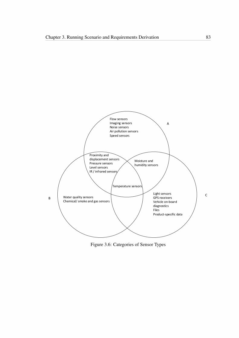
Chapter 3. Running Scenario and Requirements Derivation 83
Temperature sensors
Light sensorsGPS receiversVehicle on-board diagnosticsFiles
Product-specific data
A
CB Water quality sensors
Chemical/ smoke and gas sensors
Flow sensorsImaging sensorsNoise sensorsAir pollution sensors
Speed sensors
Proximity and displacement sensorsPressure sensorsLevel sensorsIR / infrared sensors
Moisture and humidity sensors
Figure 3.6: Categories of Sensor Types
Chapter 3. Running Scenario and Requirements Derivation 84
as pressure sensors, temperature sensors and water quality sensors are used. Pressure
sensors are used to detect the water flow through pipes and reduce water wastage and
temperature sensors measure the temperature of plants, soil and water. Similarly, in
manufacturing sensors are used for quality management by incorporating them in the
machines so that if there is any change in the required quality levels, the sensors will
detect them e.g. temperature sensors measure the temperature of machines.
In the problem scenario we introduced in subsection two, temperature sensors of
smart sensor category are used to detect temperature in the environment while shipment
is on its way from the supplier to the customer. Sensors keep monitoring temperature to
maintain the quality and condition of the goods while transportation and any violations
are reported back to suppliers by using Cloud GPS technology.
There are various types of sensors, which can be used in IoT applications. (Rayes &
Samer, 2017) categorises sensors into eleven types. They are temperature sensors, pres-
sure sensors, flow sensors, level sensors, imaging sensors, noise sensors, air pollution
sensors, proximity and displacement sensors, infrared sensors, moisture and humidity
sensors, and speed sensors. Sensor characteristics they identify are data filtering, min-
imum power consumption, compact, smart detection, high sensitivity, linearity, dynamic
range, accuracy, hysteresis, limited noise, wide bandwidth, high resolution, minimum
interruption, higher reliability and ease of use. According to (Tracy, 2016) sensor types
for many IoT use-cases are temperature sensors, proximity sensors, pressure sensors,
water quality sensors, chemical/smoke and gas sensors, level sensors and IR sensors.
(Biron & Follett, 2016) identifies sensors as, temperature sensors light sensors, mois-
ture sensors, GPS receivers, vehicle on-board diagnostics, files, and product-specific
data. (bootcamplab.com, 2017) describes sensor characteristics as range, drift, sensitiv-
ity, selectivity, resolution, response and recovery time, linearity, hysteresis, calibration,
full-scale output, precision and accuracy. Whereas, according to (Kalantar-Zadeh, 2013)
sensor characteristics are accuracy, precision, repeatability, reproducibility, stability,

Chapter 3. Running Scenario and Requirements Derivation 85
AccuracySensitivityResolutionLinearityHysteresisRange Repeatability
ReproducibilityStabilityErrorMinimum detectable signal
Calibration Curve
A
CB
SensitivityResolutionLinearityHysteresisFull-Scale OutputAccuracy
Data FilteringMinimum power consumptionCompactSmart DetectionWide BandwidthMinimum InterruptionHigher reliabilityEase of use
Noise
DriftCalibrationSelectivityResponse and recovery timePrecision
Figure 3.7: Categories of Sensor Characteristics
Chapter 3. Running Scenario and Requirements Derivation 86
error, noise, drift, resolution, minimum detectable signal, calibration curve, sensitivity,
linearity, selectivity, hysteresis, measurement range, and response and recovery time.
Categories of sensor types are shown in Figure 3.6. Circle A denotes (Rayes & Samer,
2017), B - (Tracy, 2016) and C - (Biron & Follett, 2016). Temperature sensors are
common to all three references. Moisture and humidity sensors are shared by (Rayes
& Samer, 2017) and (Biron & Follett, 2016) whereas, proximity and displacement,
pressure, level IR or infrared sensors are common to (Rayes & Samer, 2017) and (Tracy,
2016).
Sensor characteristics common to three of the references are accuracy, sensitivity,
resolution, linearity, hysteresis and range. The characteristics, drift, calibration, selectiv-
ity, response and recovery time and precision are common to (bootcamplab.com, 2017)
and (Kalantar-Zadeh, 2013) whereas, the characteristic noise is shared by (Rayes &
Samer, 2017) and (Kalantar-Zadeh, 2013). Therefore, these common characteristics are
chosen to represent sensor attributes.
• Range/ dynamic range/ span - Sensing range within which, the sensor works well.
This range produces accurate and meaningful output (with an acceptable error).
• Accuracy - How correct the sensor output is compared with its true input value.
For example if an oxygen gas sensor records 21.1 percent in a room with 21
percent oxygen level, it is more accurate than if it shows 22 percent.
• Sensitivity - The change in sensors output to the measured change in its input.
• Selectivity - The sensor’s capability in selecting and differentiating the target to
measure among other interfering targets. For example, a sensor for oxygen gas
should not respond to other gases such as carbon dioxide or nitrogen dioxide.
• Resolution - Signal fluctuation of a sensor detected at its minimum. Minimum
change in the target input will reflect a detectable change in the output signal.

Chapter 3. Running Scenario and Requirements Derivation 87
Sensor
Sensing activity()
Temperature Sensor
Proximity Sensor
Long functional life
Moisture & Humidity Sensor
Sensing region
IR or Infrared Sensor
Wavelength region
Pressure Sensor
High reliability
Level Sensor
High repeatability
Light SensorRangeAccuracySensitivitySelectivity
LinearityResponse and Recovery Time
Precision
HysteresisCalibration
NoiseDrift
ResolutionInterface type
Active/ PassiveSimple/ Smart
Anticipated use
Photo-voltaic/ photo-emissive Photo-resistor/ photo-conductor
High reliability
Nominal rangeNo physical contact
Operative range Long life spanDirect conversion from pressure to electrical signal
Active areaStability
AdaptabilityLiquid level detectionLong life spanHigh reliability
StabilityInterchangeability
Figure 3.8: UML class diagram for Sensors
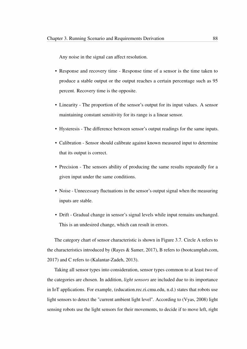
Chapter 3. Running Scenario and Requirements Derivation 88
Any noise in the signal can affect resolution.
• Response and recovery time - Response time of a sensor is the time taken to
produce a stable output or the output reaches a certain percentage such as 95
percent. Recovery time is the opposite.
• Linearity - The proportion of the sensor’s output for its input values. A sensor
maintaining constant sensitivity for its range is a linear sensor.
• Hysteresis - The difference between sensor’s output readings for the same inputs.
• Calibration - Sensor should calibrate against known measured input to determine
that its output is correct.
• Precision - The sensors ability of producing the same results repeatedly for a
given input under the same conditions.
• Noise - Unnecessary fluctuations in the sensor’s output signal when the measuring
inputs are stable.
• Drift - Gradual change in sensor’s signal levels while input remains unchanged.
This is an undesired change, which can result in errors.
The category chart of sensor characteristic is shown in Figure 3.7. Circle A refers to
the characteristics introduced by (Rayes & Samer, 2017), B refers to (bootcamplab.com,
2017) and C refers to (Kalantar-Zadeh, 2013).
Taking all sensor types into consideration, sensor types common to at least two of
the categories are chosen. In addition, light sensors are included due to its importance
in IoT applications. For example, (education.rec.ri.cmu.edu, n.d.) states that robots use
light sensors to detect the "current ambient light level". According to (Vyas, 2008) light
sensing robots use the light sensors for their movements, to decide if to move left, right
Chapter 3. Running Scenario and Requirements Derivation 89
or straight according to the light. Sensor characteristics common to at least two groups
of characteristics are chosen as sensor properties. Figure 3.8 illustrates a UML class
diagram for chosen sensor types and sensor properties. According to (coep.vlab.co.in,
2011), temperature sensor characteristics are
• Interface type – for example 15C.
• Anticipated use – what it is used for, for example heating or cooling a system.
Whereas, according to (coep.vlab.co.in, 2011) temperature sensor characteristics in-
cludes stability and interchangeability. (Mathas, 2012) states that light sensors can be
separated into two groups.
• Photo-voltaic or photo-emissive which generates electricity once illuminated.
• Photo-resistor or photo-conductor which changes its electrical properties in some
way
(OMRON, 2017) defines Object detection without touch and longer service life
as two of the features of proximity sensors. (wikipedia, 2017) states that proximity
sensors have a nominal range in which they detect objects, high reliability, no physical
contact between the sensor and the object being sensed and long functional life due to
no mechanical parts and no physical contact. According to (T.L.YeoT.SunK.T.V.Grattan,
2008) moisture and humidity sensors have a sensing region as a feature and (Yamazoe &
Shimizu, 1986) defines operative range as another feature. According to (panasonic.biz,
n.d.) pressure sensors have high reliability and long life due to lack of mechanical
parts and have the ability of direct conversion from pressure to an electrical signal
IR or Infrared sensor characteristics are stability, active area and wavelength region.
(Kazuma Maekawa, 2017) defines dynamic level detection as a characteristic of level
sensors and (Yao, 2017) defines adaptability, long life, high reliability, high repeatability
as level sensor characteristics.
Chapter 3. Running Scenario and Requirements Derivation 90
3.3.2 Requirement 2 (R2): Actuator as the Business Process Mod-
elling Requirement for IoT
Actuators are the opposite of sensors where actuators act as output transducers in IoT
applications. According to (Vladimer, 2015), “an actuator transforms electrical data
into interesting, useful energy”. Example of simple actuators are loudspeaker and
display screen of a smart phone. Sensors collect data through sensing activity and send
to a control system, which in turn makes a decision based on the sensing data and sends
to an actuator to take action. (Rouse, 2017) defines an actuator as a "mechanism for
turning energy into motion" and based on the energy source actuators use to generate
motion, they can be divided into four groups. They are:
• Pneumatic actuators, which generate motion using compressed air.
• Hydraulic actuators, which generate motion with the help of liquid.
• Electric actuators, which generate motion by an external power source like battery
power.
• Thermal actuators, which generate motion by a source of heat.
(Rayes & Samer, 2017) defines actuators as certain types of motors, which control
or perform some action in a system by converting data or energy to action. In an IoT
system, actuators take action or control an IoT system by making use of collected data
through sensing or by other means. For an example, an actuator increases or decreases
temperature in an air-conditioned room depending on sensor readings for required levels
of cooling. Some types of actuators are electrical actuators, mechanical linear actuators,
hydraulic actuators, pneumatic actuators and manual actuators. (wdc65xx.com, 2016)
categorises actuators into five main types. They are hydraulic, pneumatic, electrical,
thermal or magnetic and mechanical. According to, (Biron & Follett, 2016) actuators
are lights, valves, motors and commands.
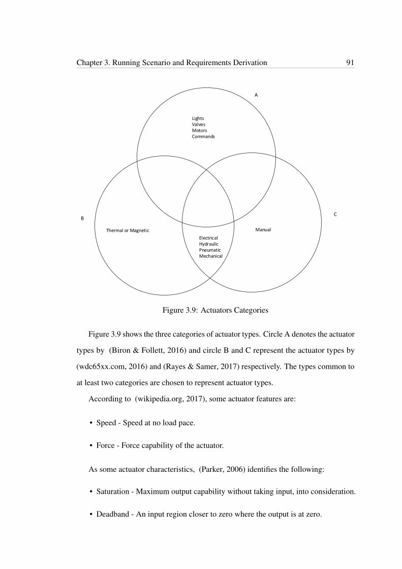
Chapter 3. Running Scenario and Requirements Derivation 91
LightsValvesMotorsCommands
Manual Thermal or Magnetic
ElectricalHydraulicPneumaticMechanical
A
BC
Figure 3.9: Actuators Categories
Figure 3.9 shows the three categories of actuator types. Circle A denotes the actuator
types by (Biron & Follett, 2016) and circle B and C represent the actuator types by
(wdc65xx.com, 2016) and (Rayes & Samer, 2017) respectively. The types common to
at least two categories are chosen to represent actuator types.
According to (wikipedia.org, 2017), some actuator features are:
• Speed - Speed at no load pace.
• Force - Force capability of the actuator.
As some actuator characteristics, (Parker, 2006) identifies the following:
• Saturation - Maximum output capability without taking input, into consideration.
• Deadband - An input region closer to zero where the output is at zero.
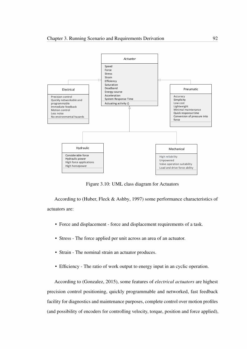
Chapter 3. Running Scenario and Requirements Derivation 92
Actuator
Actuating activity ()
Electrical
Precision control
Hydraulic
Considerable force
Mechanical
High reliability
Pneumatic
Accuracy
UnpoweredHydraulic power
Valve operation suitability
System Response Time
Speed
SaturationEfficiencyStrainStressForce
Deadband
Acceleration
Quickly networkable and programmableImmediate feedbackMotion controlLess noiseNo environmental hazards
High force applicationsHigh horsepower
Simplicity Low costLightweightMinimal maintenanceQuick response timeConversion of pressure into force
Load and drive force ability
Energy source
Figure 3.10: UML class diagram for Actuators
According to (Huber, Fleck & Ashby, 1997) some performance characteristics of
actuators are:
• Force and displacement - force and displacement requirements of a task.
• Stress - The force applied per unit across an area of an actuator.
• Strain - The nominal strain an actuator produces.
• Efficiency - The ratio of work output to energy input in an cyclic operation.
According to (Gonzalez, 2015), some features of electrical actuators are highest
precision control positioning, quickly programmable and networked, fast feedback
facility for diagnostics and maintenance purposes, complete control over motion profiles
(and possibility of encoders for controlling velocity, torque, position and force applied),
Chapter 3. Running Scenario and Requirements Derivation 93
less noise and no environment hazards due to lack of fluid leaks. (wdc65xx.com, 2016)
mention that use of hydraulic power, ability to apply considerable force and limited
acceleration are a few characteristics of hydraulic actuators and (Gonzalez, 2015)
states that applicability for high force applications and possession of high horsepower
include hydraulic actuators characteristics. (wdc65xx.com, 2016) states that quick
response time, conversion of pressure into force as pneumatic actuator features and
according to (Gonzalez, 2015) they are, simplicity, precise linear motion by resulting
accuracy, low cost, lightweight and least maintenance. According to (wdc65xx.com,
2017), mechanical actuators possess the characteristics such as they are not powered,
ability of specific load and drive force, mainly use for operation of valves and high
reliability.
Figure 3.10 shows the UML class diagram for actuators. In the problem scenario
we introduced, actuators are used to maintain the quality of goods by maintaining their
required temperature levels while transporting them from supplier to customer.
3.3.3 Requirement 3 (R3): Reader as the Business Process Model-
ling Requirement for IoT
Readers are also input devices in IoT systems. They collect actual input data, which are
to be transformed into an electronic form to be transferred via a network in order to be
made available for use. Two important features of readers are automatic identification
and automatic data capture (Journal, 2017), i.e. automatic identification of objects
and obtaining information about them without any human mediation. Famous types
of readers are Barcode Readers and RFID readers. According to (atlasrfid.com, 2017)
some of the common features of readers are:
• Read rate – The rate at which the things can be read.

Chapter 3. Running Scenario and Requirements Derivation 94
Reader
Accuracy
Reading activity ()Output results ()
EfficiencyRead rangeRead rate
RFID Readers
Line of sight not needed
Read/ write/ modify/ update
High security
Barcode Readers
Line of sight requiredDecoding capability
Read onlyHigh read rate
Processing capability
ReliabilitySpeedSecurity
Line of sight requirementEvent triggering capabilityRead only/ read-write capability
Wireless information tracking
Event triggeringFast response time
Response time
Automatic data capture
Contact reading/ non-contact readingNo event triggering
Unique Identification
Non-contact Reading
Automatic identification
Figure 3.11: UML class diagram for Readers
• Line of sight requirement – If the item to read is required to position in a specific
direction.
• Read and write capability – The ability to read and write or read only.
• Event triggering – The ability to trigger an event such as opening a door.
• Security – The ability to protect data such as encryption and to remove data after
use.
Figure 3.11 illustrates the UML class diagram for Readers.
Chapter 3. Running Scenario and Requirements Derivation 95
RFID readers
RFID has its advantages over bar codes due to its unique identification feature. RFID
technology facilitates automatic identification of objects by use of radio waves, generally
with help of serial numbers to uniquely identify objects. RFID reader and a tag make a
RFID system. The tag consists of a microchip and an antenna. (Journal, 2017). The
chip contains the information about the item it is attached to. The antenna receives and
returns radio waves from the reader. Readers also contain an antenna, which sends out
radio signals to the tags and receives returning signals from the tags. Readers capture
unique identification information of the items the tags are attached to. In certain types,
the reader possesses the ability to write information on the tags. The reader’s software
finally passes the item information to the back end system for processing and storage
(redbeam.com, 2015).
Active RFID tags contain batteries to power their chips to send signals to the reader.
Whereas, passive tags do not contain batteries. They receive power from the reader’s
electromagnetic signals, which power the tag’s antenna. Semi passive tags contain
battery power to run the chips though they communicate by obtaining power from the
readers. (Journal, 2017). According to (atlasrfid.com, 2017), direct line of sight of
items is not a requirement for RFID readers for reading. The items within the read
range is sufficient. In addition, there is high security and event triggering, i.e. triggering
an event as such as opening a door, is possible.
RFID has variety of uses in the world. Injectable RFID chips can be inserted in
animals and used for livestock and wildlife tracking and also in patients who are unable
to communicate to trace their medical history and information. RFID technology is used
in many large retail companies in the word, such as fashion industry. They make use
of this technology to benefit their businesses. This reduces time spent on stocktaking,
making the process more accurate and finally guaranteeing customer satisfaction. By
Chapter 3. Running Scenario and Requirements Derivation 96
using a hand-held RFID reader, large items of stock can be counted at once saving time
spent on stock taking as visible contact and line of sight of items is not a requirement
for RFID readers. As a result of accurate stock taking, out of stock situations can be
prevented. What is more, RFID tags can be attached to products to make it much easier
to differentiate them according to their sizes, colours, etc. This makes stock taking
accurate and losing the chances of ordering the wrong items when stock reaches the
re order levels. Moreover, searching for a particular item such as a different size of
the same brand in the back room where items are stored, while a customer waits in the
show room becomes much quicker and easier using this technology, due to its unique
identification feature. Furthermore, tamper-proof RFID technology is used to safeguard
security sensitive items such as aircraft life jackets and valuable products.
Barcode Readers
Barcodes contain different information. Generally, there are three parts. First part
contains the information of the country of manufacture, second part comes with the
manufacture information and the final part consists of product information (Woodford,
2016). There are different types of barcode readers. Pen type readers use the light and
a photo device as the technology in reading barcodes (TalTec, 2017). It reads as the
reader passes through the barcode. The attached photo device measures the barcodes
with the help of the light for the widths and the spaces in them. CCD (charge coupled
device) readers contain hundreds of sensors attached to it. Each sensor consists of a
small photo device, which measures the barcodes using light. Camera based barcode
readers consist of a tiny video camera to read barcodes. The camera captures an image
of the barcode and decodes it by using digital image processing techniques. Generally,
barcode readers should be in line of sight of the bar-coded item in order to read it
(redbeam.com, 2015). According to (streetdirectory.com, 2017), barcode readers can be
categorised into two main categories, they are:
Chapter 3. Running Scenario and Requirements Derivation 97
• Contact readers – These are generally hand held devices and the barcodes should
touch the reader or come close contact with the reader for reading.
• Non-contact readers – These are opposite to the above where it is not required for
the barcode to be close to the reader to read the code. These readers generally
consist of a moving laser light beam.
Barcode technology offers automatic product identification and is famous in invent-
ory management systems. They are simple and cheaper to use than RFID technology.
Barcodes are used throughout supply chain management such as for inventory counts,
receiving inventory, order picking and warehouse transfers. Barcode technology can be
used alone or together with RFID technology in certain parts of supply chain manage-
ment for better accuracy. For example, when RFID readers read boxes of items at once,
the same boxes with bar-coded labels containing item counts of items inside the boxes
can be compared with each other for accuracy.
3.3.4 Requirement 4 (R4): Collector as the Business Process Mod-
elling Requirement for IoT
Collectors are input devices of IoT applications where they collect information from
various resources. According to (Yousfi et al., 2016), collectors are used to collect
context information apart from sensors and readers, unusually form databases, files
or output of processes. Data collections from collectors are stored temporarily in
data objects or permanently in data stores depending on the requirement. In the work
of (Yousfi et al., 2016), collectors are represented by extending BPMN task and inherits
the attributes of BPMN activities. According to (Model, 2011) some attributes of
BPMN activities are atomic activity, re-usability, source or target for a sequence flow
and source or target of a message flow.
Chapter 3. Running Scenario and Requirements Derivation 98
In the problem scenario we have introduced, when the stock reaches their re-
order levels, collectors automatically collect re-order level information from inventory
database and issue re-order requests to purchasing department. Moreover, in purchasing
section collectors are used to retrieve supplier information from supplier database to
select suitable suppliers to send requests for stock.
3.3.5 Requirement 5 (R5): Event streaming (event stream processing
units) as the Business Process Modelling Requirement for
IoT
Events are inputs to IoT applications. Events can be single events or streams of events.
Generally, in IoT systems events are represented as streams of events. Event streaming
is continuous occurring of new events over a time period. For example, continuous
reading of temperature sensors to track temperature changes in a shipment to monitor
and maintain the quality of goods in transit. (Appel et al., 2014) in their work introduce
SPUs (Event Stream Processing Units) for processing new events. SPUs process events
as they occur and process continuous occurring of new events by streams rather than
single events. Events are produced in an independent nature without any knowledge of
their consumption. Therefore, the following can be derived as SPU attributes.
• Processing continuous occurring of events – SPUs are used to process events as
streams as and when they occur.
• Event streaming functionality – SPUs contain functionality for event streaming.
• Event streaming logic – SPUs contain and process application logic.
• Encapsulate application logic – SPUs encapsulate event stream processing logic
enabling a smooth transition between different layers.
Chapter 3. Running Scenario and Requirements Derivation 99
SPUs introduced in (Appel et al., 2014) is used in our problem scenario, to process
event streams produced by temperature changes during the shipping of goods from
customer to supplier. Shipment is monitored for temperature conditions to maintain
the quality of goods by use of temperature sensors. Temperature sensors continue
to read temperature as streams of events during the shipment of goods from supplier
to customer. Monitoring temperature as streams of events as new events continue to
occur, any deviations to the required temperature levels of goods can be detected and
eliminated.
3.3.6 Requirement 6 (R6): Specific data object as the Business Pro-
cess Modelling Requirement for IoT
These are the input data or things in an IoT application such as RFID tags, Bar Codes,
Magnetic stripes, etc. In (Yousfi et al., 2016), authors name specific data Object
as smart object and define it as data collection by either sensors or readers such as
RFID readers and Barcode readers. According to them, smart object inherits the
attributes of BPMN DataInput element. In (Goumopoulos, Kameas & Hellas, n.d.),
smart objects are seen as important components connecting the physical world and
digital world by providing information on their physical environments. According to
(Model, 2011) attributes of BPMN DataInput element are, Name (type: string) and
IsCollection (type: boolean). DataInput element inherits the attributes and associations
of BaseElement and ItemAwareElement. BaseElement contain the attributes, Id (type:
string), Documentation, ExtensionDefinitions and ExtensionValues. ItemAwareElement
contains the attribute isCollection (type: boolean = false). Furthermore, DataInput
element has features such as they may have incoming Data Associations.
In our problem scenario, we relate specific data Objects to barcodes and RFID tags
attached to items of stock enabling accurate stock taking.

Chapter 3. Running Scenario and Requirements Derivation 100
3.3.7 Requirement 7 (R7): Intermediary operation as the Business
Process Modelling Requirement for IoT
After receiving input, Intermediary operation performs some processing inside an IoT
application before passing output. According to (Sungur et al., 2013), intermediary
operations receive data from outside, do some computation within the system and
send data to outer world. For example, in a wireless sensor network system, interme-
diary operation takes sensory temperature level as input to decide if the temperature
of an air-conditioned room is maintained within the required level (Sungur et al.,
2013). (Tranquillini et al., 2012) name this as data operators and state that it should be
useful to apply some computations on data while in transmission before outputting the
results. Therefore, intermediary operation can be taken as an element responsible for
raw context data processing.
In the problem scenario we introduced, the intermediary operation is used to decide
on re-order if certain items are at their re-order levels (after checking the inventory
database).
3.4 Conclusion
In this chapter we identified seven IoT modelling elements as requirements for business
process modelling for IoT. These are sensor, actuator, reader, collector, event streaming,
intermediary operation and specific data object. We derived these requirements from a
problem scenario based on an IoT aware business application, i.e. part of supply chain
management. We modelled this process using BPMN 2.0. Each identified requirement
was further elaborated in detail. Class diagrams were used for some cases illustrating
the hierarchy and inherited properties.
Chapter 4
Implementation of IoT Modelling
Elements
4.1 Introduction
In chapter three, we identified seven IoT modelling elements as business process
modelling requirements for IoT. In this Chapter, we design those elements as extensions
to BPMN 2.0 and implement them using a web based BPMN editor tool. For this
purpose, we develop a web based IoT aware BPMN editor with XPDL capabilities by
extending an existing software system to include new IoT modelling elements. We
add these IoT modelling elements to the toolkit of the editor inside the relevant BPMN
category. We introduce the new IoT modelling elements sensor, actuator, reader,
collector, intermediary operation, event stream processing as Task elements under
BPMN Activities in this system. We add IoT modelling element, specific data object as
smart object to the BPMN Data and Artifacts category. Furthermore, we introduce three
new IoT modelling elements, input event stream, output event stream, (as data objects)
and physical entity, and include them in BPMN Data and Artifacts group. Section
4.2 introduces the BPMN editor we chose to extend. In section 4.3, we describe our
101
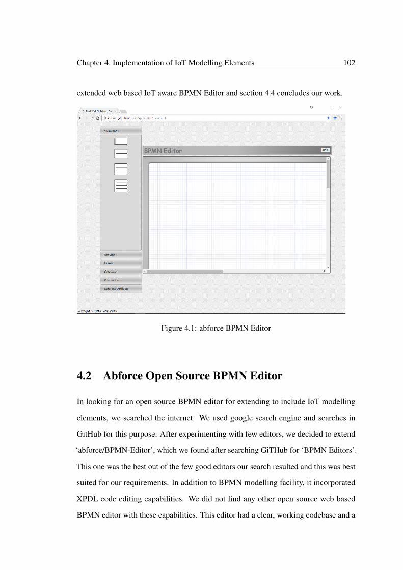
Chapter 4. Implementation of IoT Modelling Elements 102
extended web based IoT aware BPMN Editor and section 4.4 concludes our work.
Figure 4.1: abforce BPMN Editor
4.2 Abforce Open Source BPMN Editor
In looking for an open source BPMN editor for extending to include IoT modelling
elements, we searched the internet. We used google search engine and searches in
GitHub for this purpose. After experimenting with few editors, we decided to extend
‘abforce/BPMN-Editor’, which we found after searching GiTHub for ‘BPMN Editors’.
This one was the best out of the few good editors our search resulted and this was best
suited for our requirements. In addition to BPMN modelling facility, it incorporated
XPDL code editing capabilities. We did not find any other open source web based
BPMN editor with these capabilities. This editor had a clear, working codebase and a
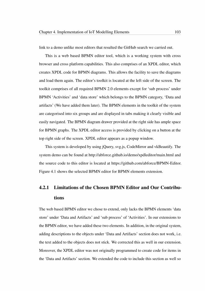
Chapter 4. Implementation of IoT Modelling Elements 103
link to a demo unlike most editors that resulted the GitHub search we carried out.
This is a web based BPMN editor tool, which is a working system with cross
browser and cross platform capabilities. This also comprises of an XPDL editor, which
creates XPDL code for BPMN diagrams. This allows the facility to save the diagrams
and load them again. The editor’s toolkit is located at the left side of the screen. The
toolkit comprises of all required BPMN 2.0 elements except for ‘sub process’ under
BPMN ‘Activities’ and ‘data store’ which belongs to the BPMN category, ‘Data and
artifacts’ (We have added them later). The BPMN elements in the toolkit of the system
are categorised into six groups and are displayed in tabs making it clearly visible and
easily navigated. The BPMN diagram drawer provided at the right side has ample space
for BPMN graphs. The XPDL editor access is provided by clicking on a button at the
top right side of the screen. XPDL editor appears as a popup window.
This system is developed by using jQuery, svg.js, CodeMirror and vkBeautify. The
system demo can be found at http://abforce.github.io/demo/xpdleditor/main.html and
the source code to this editor is located at https://github.com/abforce/BPMN-Editor.
Figure 4.1 shows the selected BPMN editor for BPMN elements extension.
4.2.1 Limitations of the Chosen BPMN Editor and Our Contribu-
tions
The web based BPMN editor we chose to extend, only lacks the BPMN elements ‘data
store’ under ‘Data and Artifacts’ and ‘sub process’ of ‘Activities’. In our extensions to
the BPMN editor, we have added these two elements. In addition, in the original system,
adding descriptions to the objects under ‘Data and Artifacts’ section does not work, i.e.
the text added to the objects does not stick. We corrected this as well in our extension.
Moreover, the XPDL editor was not originally programmed to create code for items in
the ‘Data and Artifacts’ section. We extended the code to include this section as well so
Chapter 4. Implementation of IoT Modelling Elements 104
that the complete diagram can be translated to XPDL for storing and distributing.
There are few minor limitations still exist in the system such as no multiple pool
representation, limiting only to a single pool with multiple lanes. Therefore, representing
business to business collaborations with process choreographies are not possible. In
addition, when a pool consists of two or more lanes, each lane cannot be individually
labelled, only the pool can have a common label. It is also not possible to resize any
modelling element in this system.
Figure 4.2: Appearance of our IoT aware BPMN and XPDL editor
4.2.2 How the Chosen System Works
Following are the instructions to use abforce BPMN Editor for BPMN diagrams.
• Choose a single, double, triple lane pool or a pool with four lanes by clicking on
the required object under ‘Swimlanes’.
• To use a ‘task’ element under ‘Activities’ section, you have to click on it and drag
Chapter 4. Implementation of IoT Modelling Elements 105
it to the pool or lane on screen. The same process is to follow for the elements
under ‘Events’, ‘Gateways’ and ‘Data and Artifacts’ sections.
• To use a ‘connector’ element under ‘Connectors’, click on it (it gets heighted),
move the cursor to one of the two objects you want to connect with each another.
The object changes its colour to yellow. Click on the object and drag the cursor
to the other object you want to connect it. To deselect the connector, click on the
connector (selected) in the toolkit again.
• To add text to an element, double click on it and a text area window will appear.
Write on it and click on ‘Set’ button on it so that the text area will disappear and
the written text would appear on the object. ‘Cancel’ button is to discard any
change and exit the text area window. To modify what is already written, follow
the same steps.
• To delete any element, right click on it and select the ‘Delete’ option from the
menu, which will appear. This will delete the selected object and any associations
as well. Make sure to deselect any connector elements if already selected from
the ‘Connectors’ tab and is being highlighted since this will prevent the menu
appearing on right click.
• There is an XPDL Editor, which can be opened by clicking on the XPDL button
on the top right side of the screen. XPDL Editor creates the XPDL (XML Process
Definition Language) code to store the diagram drawn and, which translate the
code into diagrams as well. Therefore, to save a BPMN diagram, the code inside
the XPDL editor should be saved into a file and to load the diagram back, the
same code should be copied back to the editor.

Chapter 4. Implementation of IoT Modelling Elements 106
4.3 Our Web Based IoT Aware BPMN and XPDL Ed-
itor
We extended the above mentioned BPMN and XPDL editor to facilitate business process
modelling for IoT with BPMN. We have extended BPMN 2.0 modelling elements in
introducing our IoT modelling elements into the editor’s toolkit. The BPMN elements
in this toolkit are divided into six categories, swimlanes, activities, events, gateways,
connectors and, data and artifacts. We have introduced six new IoT modelling elements
to BPMN ‘Activities’ and four new IoT modelling elements to ‘Data and Artifacts’.
Figure 4.2 shows the appearance of our IoT aware BPMN system.
Collapsed sub process Data store
Figure 4.3: Two missing BPMN elements we have added to the system
The following two BPMN elements are not available in the original system and we
have added them to our new system. Figure 4.3 shows these two new elements.
• Collapsed sub process under ‘Activities’
• Data store under ‘Data and Artifacts’.
4.3.1 Software Architecture
Figure 4.4 depicts a high-level software architecture of the system. This IoT aware
BPMN modelling tool comprises of both graphical representation of BPMN process

Chapter 4. Implementation of IoT Modelling Elements 107
Web based BPMN & XPDL Editor
BPMN diagramming tool
BPMN Editor
Tool kit to create diagrams
XPDL Editor
XPDL code generation
Swimlanes/ Pools
Single lane poolDouble lane poolTriple lane poolFour lane pool
Activities
Normal TaskCollapsed sub ProcessSensing TaskActuating Task
Events
General StartGeneral EndGeneral IntermediateTimer Start
Gateways
GatewayGateway AndGateway Xor (event)Gateway Xor (data)
Swimlanes/ Pools
AnnotationGroupData ObjectData store
Connectors
Default Sequence FlowConditional Sequence FlowMessage FlowNormal Sequence Flow
Reading TaskCollecting TaskIntermediary TaskEvent stream processing task
TerminateRule StartRule IntermediateRule EndMultiple StartMultiple IntermediateMessage StartMessage IntermediateMessage EndLink StartLink IntermediateLink EndError IntermediateError EndCompensation IntermediateCompensation EndCancel End
Gateway OrGateway Complex
Association W ArrowAssociation
Smart ObjectInput Event StreamOutput Event StreamPhysical Entity
XPDL code editing/ loading
XPDL editor interface
Interface for graphics
Figure 4.4: Software architecture of IoT aware BPMN and XPDL editor.
models as well as storing them using XPDL code. There are six categories of BPMN
modelling elements. The first category, swimlanes/ pools contains four modelling
elements, single lane pool, double lane pool, triple lane pool and four lane pool. Ele-
ments under the category, activities are, normal task, collapsed sub process, sensing
task, actuating task, reading task, collecting task, intermediary task and event stream
processing task. The category events, consists of the elements general start, general
end, general intermediate, timer start, terminate, rule start, rule intermediate, rule end,
multiple start, multiple intermediate, message start, message intermediate, message
end, link start, link intermediate, link end, error intermediate, error end, compensation
intermediate, compensation end and cancel end. Gateways category includes gateway,
gateway and, gateway xor (event), gateway xor (data), gateway or, and gateway com-
plex. Elements under connectors are default sequence flow, conditional sequence flow,
message flow, normal sequence flow, association w arrow and association. Data and
artifacts category has the modelling elements, annotation, group, data object, data store,
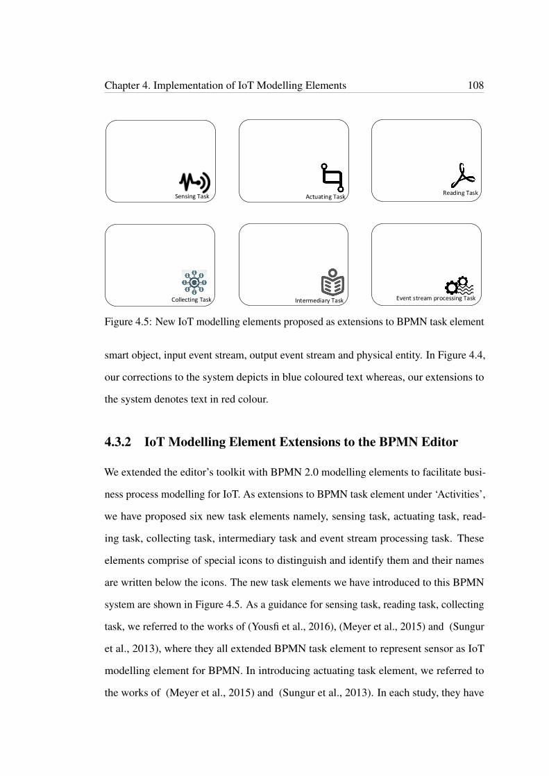
Chapter 4. Implementation of IoT Modelling Elements 108
Actuating TaskSensing TaskReading Task
Collecting Task Intermediary Task Event stream processing Task
Figure 4.5: New IoT modelling elements proposed as extensions to BPMN task element
smart object, input event stream, output event stream and physical entity. In Figure 4.4,
our corrections to the system depicts in blue coloured text whereas, our extensions to
the system denotes text in red colour.
4.3.2 IoT Modelling Element Extensions to the BPMN Editor
We extended the editor’s toolkit with BPMN 2.0 modelling elements to facilitate busi-
ness process modelling for IoT. As extensions to BPMN task element under ‘Activities’,
we have proposed six new task elements namely, sensing task, actuating task, read-
ing task, collecting task, intermediary task and event stream processing task. These
elements comprise of special icons to distinguish and identify them and their names
are written below the icons. The new task elements we have introduced to this BPMN
system are shown in Figure 4.5. As a guidance for sensing task, reading task, collecting
task, we referred to the works of (Yousfi et al., 2016), (Meyer et al., 2015) and (Sungur
et al., 2013), where they all extended BPMN task element to represent sensor as IoT
modelling element for BPMN. In introducing actuating task element, we referred to
the works of (Meyer et al., 2015) and (Sungur et al., 2013). In each study, they have

Chapter 4. Implementation of IoT Modelling Elements 109
extended BPMN task element. We followed the existing literature work of (Appel
et al., 2014) in introducing the event stream processing task element to BPMN. In
introducing intermediary task, we referred to the contribution made by the scholarly
work of (Sungur et al., 2013).
Smart Object Input Event Stream Output Event Stream Physical Entity
Figure 4.6: New IoT modelling elements proposed as extensions to BPMN data element.
We also have extended BPMN data object and introduced three new data objects, to
the toolkit under ‘Data and Artifact’ category. They are smart object, input event stream
object and output event stream object. Figure 4.6 illustrates these new extensions. We
referred to the existing works of (Yousfi et al., 2016) and (Appel et al., 2014) for these
extensions. These data objects have their unique symbols to distinguish them from
BPMN data object.
We proposed an additional element to editor’s toolkit to represent physical entity.
It is represented by the symbol, ‘perishable goods’. This element can contain text
to describe what it represents (writable). We are inspired by the work of (Meyer et
al., 2015), where they represent the physical entity ‘chocolate’ with the symbol of a
‘cow’ as a separate participant. All icons used in this system are borrowed from the
internet. Figure 4.7 and 4.8 illustrate the new BPMN editor with our extensions to
BPMN elements. We also extended the XPDL editor to reflect our extensions to the
system so that BPMN diagrams with our extensions (IoT modelling elements) can be
stored in a file and loaded back through the editor. Figure 4.9 illustrates the XPDL

Chapter 4. Implementation of IoT Modelling Elements 110
Figure 4.7: BPMN System after our extensions to BPMN task element
editor with its corresponding BPMN diagram in the background.
4.3.3 IoT Modelling Elements Extensions To BPMN Meta Model
In BPMN meta model, we illustrate our proposed IoT modelling element extensions to
BPMN 2.0. Sensing task, reading task, collecting task, actuating task, event stream pro-
cessing task and intermediary task are introduced by extending BPMN task element. So
that they inherit the properties of its parent class, BPMN Activity’s attributes and model
associations. In proposing these modelling elements as extensions to BPMN standards,
we considered extending BPMN Service Task since it appears most appropriate for such
extensions as these can be taken as services, e.g. sensing physical elements. However,
according to (Yousfi et al., 2016), BPMN Task is the most suitable for integrating
these IoT modelling elements into the BPMN Meta model. This is in accordance with
the BPMN standards. The authors have performed extensive research in representing
ubiquitous technologies by extending BPMN standards. Therefore, we took the same
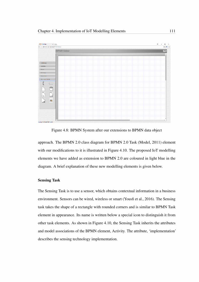
Chapter 4. Implementation of IoT Modelling Elements 111
Figure 4.8: BPMN System after our extensions to BPMN data object
approach. The BPMN 2.0 class diagram for BPMN 2.0 Task (Model, 2011) element
with our modifications to it is illustrated in Figure 4.10. The proposed IoT modelling
elements we have added as extension to BPMN 2.0 are coloured in light blue in the
diagram. A brief explanation of these new modelling elements is given below.
Sensing Task
The Sensing Task is to use a sensor, which obtains contextual information in a business
environment. Sensors can be wired, wireless or smart (Yousfi et al., 2016). The Sensing
task takes the shape of a rectangle with rounded corners and is similar to BPMN Task
element in appearance. Its name is written below a special icon to distinguish it from
other task elements. As shown in Figure 4.10, the Sensing Task inherits the attributes
and model associations of the BPMN element, Activity. The attribute, ‘implementation’
describes the sensing technology implementation.
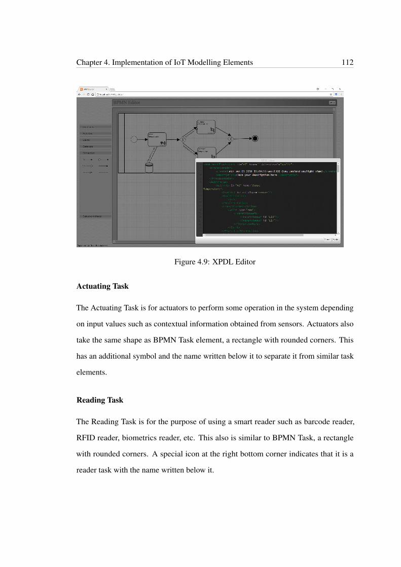
Chapter 4. Implementation of IoT Modelling Elements 112
Figure 4.9: XPDL Editor
Actuating Task
The Actuating Task is for actuators to perform some operation in the system depending
on input values such as contextual information obtained from sensors. Actuators also
take the same shape as BPMN Task element, a rectangle with rounded corners. This
has an additional symbol and the name written below it to separate it from similar task
elements.
Reading Task
The Reading Task is for the purpose of using a smart reader such as barcode reader,
RFID reader, biometrics reader, etc. This also is similar to BPMN Task, a rectangle
with rounded corners. A special icon at the right bottom corner indicates that it is a
reader task with the name written below it.
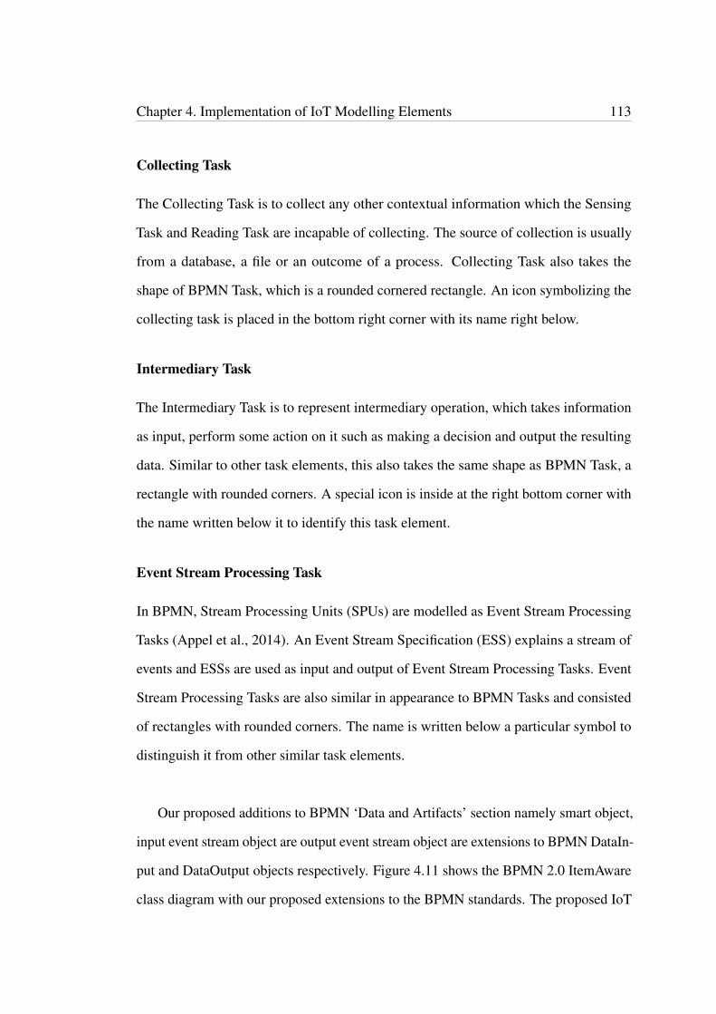
Chapter 4. Implementation of IoT Modelling Elements 113
Collecting Task
The Collecting Task is to collect any other contextual information which the Sensing
Task and Reading Task are incapable of collecting. The source of collection is usually
from a database, a file or an outcome of a process. Collecting Task also takes the
shape of BPMN Task, which is a rounded cornered rectangle. An icon symbolizing the
collecting task is placed in the bottom right corner with its name right below.
Intermediary Task
The Intermediary Task is to represent intermediary operation, which takes information
as input, perform some action on it such as making a decision and output the resulting
data. Similar to other task elements, this also takes the same shape as BPMN Task, a
rectangle with rounded corners. A special icon is inside at the right bottom corner with
the name written below it to identify this task element.
Event Stream Processing Task
In BPMN, Stream Processing Units (SPUs) are modelled as Event Stream Processing
Tasks (Appel et al., 2014). An Event Stream Specification (ESS) explains a stream of
events and ESSs are used as input and output of Event Stream Processing Tasks. Event
Stream Processing Tasks are also similar in appearance to BPMN Tasks and consisted
of rectangles with rounded corners. The name is written below a particular symbol to
distinguish it from other similar task elements.
Our proposed additions to BPMN ‘Data and Artifacts’ section namely smart object,
input event stream object are output event stream object are extensions to BPMN DataIn-
put and DataOutput objects respectively. Figure 4.11 shows the BPMN 2.0 ItemAware
class diagram with our proposed extensions to the BPMN standards. The proposed IoT
Chapter 4. Implementation of IoT Modelling Elements 114
modelling elements we have added as extension to BPMN 2.0 are coloured in light
blue in the diagram. Smart object and input event stream object inherit BPMN Data
Input attributes and associations, whereas, output event stream inherits the attributes and
associations of BPMN Data Output. The four new modelling elements are described
briefly below.
Smart Object
Smart Object is to use contextual data collected by either Reading Task or Sensing
Task. This is similar to BPMN Data Object in shape with two rectangles inside, a small
rectangle overlapping a slightly larger one to symbolize it and differentiate it from
BPMN Data Object. This inherits the attributes and model associations of BPMN Data
Input.
Input Event Stream
Input Event Streams act as inputs to Event Stream Processing Tasks. Events occur
as streams and are continuous inputs. This has the shape of BPMN Data Object with
an unfilled arrow above waves to symbolize it. This inherits the attributes and model
associations of BPMN Data Input.
Output Event Stream
Output Event Streams are opposite to Input Event Streams taking resulting events out
of Event Stream Processing Tasks. This also takes the shape of BPMN Data Object
with a symbol of a filled arrow above waves to differentiate it. This element inherits the
attributes and model associations of BPMN Data Output.
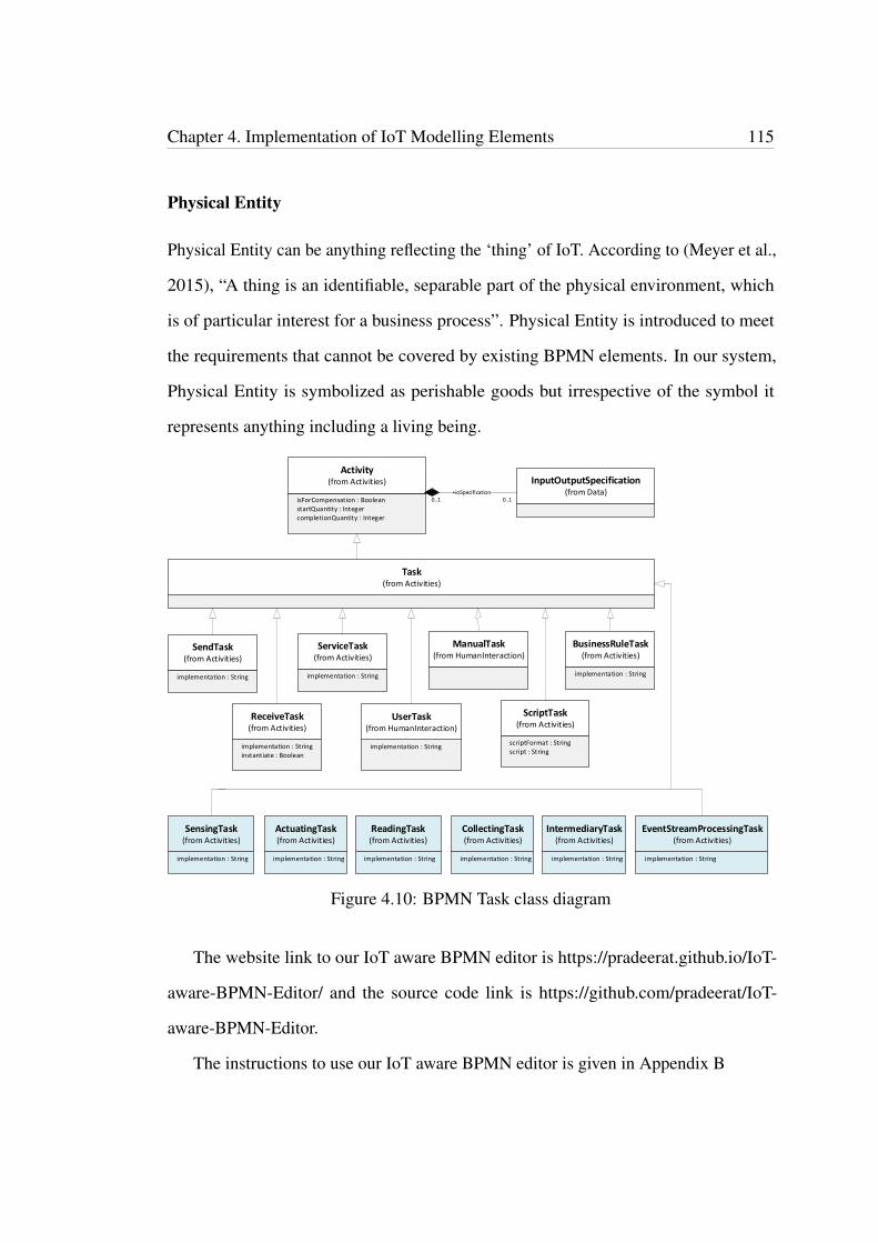
Chapter 4. Implementation of IoT Modelling Elements 115
Physical Entity
Physical Entity can be anything reflecting the ‘thing’ of IoT. According to (Meyer et al.,
2015), “A thing is an identifiable, separable part of the physical environment, which
is of particular interest for a business process”. Physical Entity is introduced to meet
the requirements that cannot be covered by existing BPMN elements. In our system,
Physical Entity is symbolized as perishable goods but irrespective of the symbol it
represents anything including a living being.
Activity(from Activities)
isForCompensation : Boolean
InputOutputSpecification(from Data)
startQuantity : IntegercompletionQuantity : Integer
0..1 0..1+ioSpecification
SendTask(from Activities)
implementation : String
ServiceTask(from Activities)
implementation : String
ManualTask(from HumanInteraction)
BusinessRuleTask(from Activities)
implementation : String
Task(from Activities)
ReceiveTask(from Activities)
implementation : Stringinstantiate : Boolean
UserTask(from HumanInteraction)
implementation : String
ScriptTask(from Activities)
scriptFormat : Stringscript : String
SensingTask(from Activities)
implementation : String
ActuatingTask(from Activities)
implementation : String
ReadingTask(from Activities)
implementation : String
CollectingTask(from Activities)
implementation : String
IntermediaryTask(from Activities)
implementation : String
EventStreamProcessingTask(from Activities)
implementation : String
Figure 4.10: BPMN Task class diagram
The website link to our IoT aware BPMN editor is https://pradeerat.github.io/IoT-
aware-BPMN-Editor/ and the source code link is https://github.com/pradeerat/IoT-
aware-BPMN-Editor.
The instructions to use our IoT aware BPMN editor is given in Appendix B
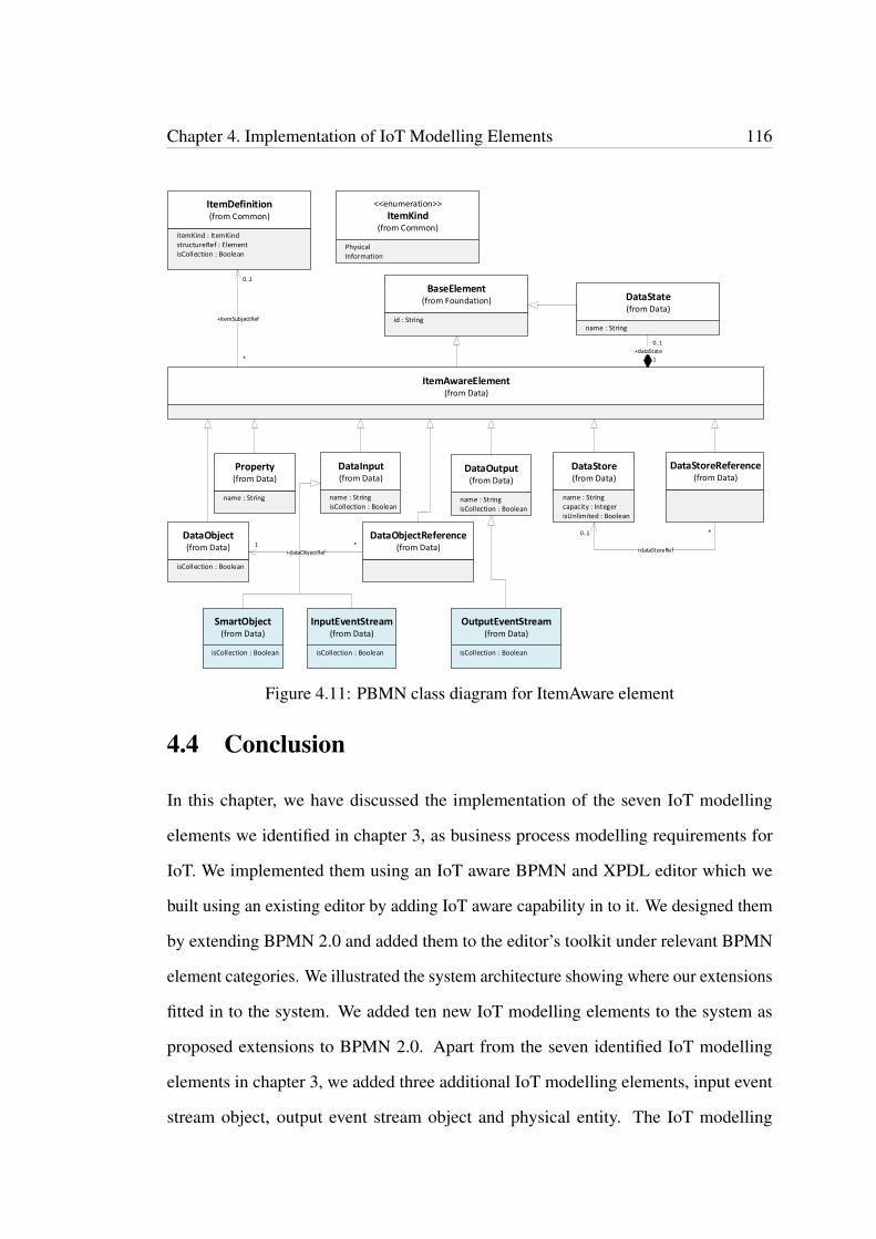
Chapter 4. Implementation of IoT Modelling Elements 116
BaseElement(from Foundation)
id : String
DataState(from Data)
name : String
1
0..1
+dataState
ItemAwareElement(from Data)
ItemDefinition(from Common)
itemKind : ItemKindstructureRef : ElementisCollection : Boolean
<<enumeration>>
ItemKind(from Common)
PhysicalInformation
Property(from Data)
name : String
DataInput(from Data)
name : StringisCollection : Boolean
DataOutput(from Data)
name : StringisCollection : Boolean
DataStore(from Data)
name : Stringcapacity : IntegerisUnlimited : Boolean
DataStoreReference(from Data)
DataObject(from Data)
isCollection : Boolean
DataObjectReference(from Data)
*
0..1
+itemSubjectRef
*1+dataObjectRef
*0..1
+dataStoreRef
SmartObject(from Data)
isCollection : Boolean
InputEventStream(from Data)
isCollection : Boolean
OutputEventStream(from Data)
isCollection : Boolean
Figure 4.11: PBMN class diagram for ItemAware element
4.4 Conclusion
In this chapter, we have discussed the implementation of the seven IoT modelling
elements we identified in chapter 3, as business process modelling requirements for
IoT. We implemented them using an IoT aware BPMN and XPDL editor which we
built using an existing editor by adding IoT aware capability in to it. We designed them
by extending BPMN 2.0 and added them to the editor’s toolkit under relevant BPMN
element categories. We illustrated the system architecture showing where our extensions
fitted in to the system. We added ten new IoT modelling elements to the system as
proposed extensions to BPMN 2.0. Apart from the seven identified IoT modelling
elements in chapter 3, we added three additional IoT modelling elements, input event
stream object, output event stream object and physical entity. The IoT modelling
Chapter 4. Implementation of IoT Modelling Elements 117
elements Sensing Task, Actuating Task, Reading Task, Collecting Task, Intermediary
Task, event stream processing Task and Smart Object represent the identified IoT
modelling requirements, sensor, actuator, reader, collector, intermediary operation, event
stream processing and specific data object respectively. We illustrated our extensions to
BPMN meta model in class diagrams. We also extended the XPDL editor incorporated
in the original BPMN editor to facilitate our extensions. In Appendix B, we provided
detailed instructions to use our IoT aware BPMN editing tool.
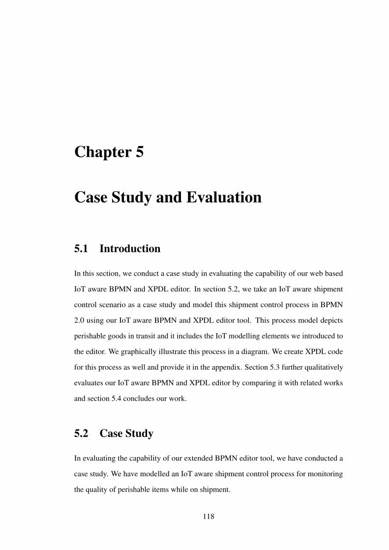
Chapter 5
Case Study and Evaluation
5.1 Introduction
In this section, we conduct a case study in evaluating the capability of our web based
IoT aware BPMN and XPDL editor. In section 5.2, we take an IoT aware shipment
control scenario as a case study and model this shipment control process in BPMN
2.0 using our IoT aware BPMN and XPDL editor tool. This process model depicts
perishable goods in transit and it includes the IoT modelling elements we introduced to
the editor. We graphically illustrate this process in a diagram. We create XPDL code
for this process as well and provide it in the appendix. Section 5.3 further qualitatively
evaluates our IoT aware BPMN and XPDL editor by comparing it with related works
and section 5.4 concludes our work.
5.2 Case Study
In evaluating the capability of our extended BPMN editor tool, we have conducted a
case study. We have modelled an IoT aware shipment control process for monitoring
the quality of perishable items while on shipment.
118
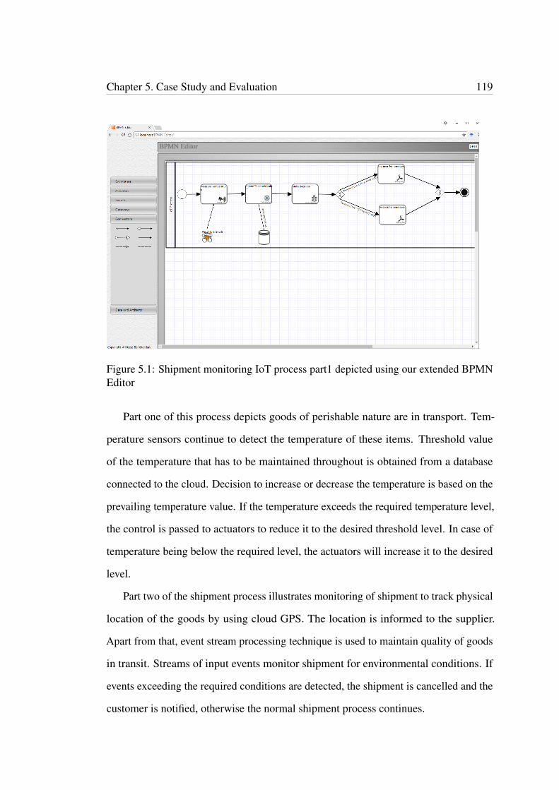
Chapter 5. Case Study and Evaluation 119
Figure 5.1: Shipment monitoring IoT process part1 depicted using our extended BPMNEditor
Part one of this process depicts goods of perishable nature are in transport. Tem-
perature sensors continue to detect the temperature of these items. Threshold value
of the temperature that has to be maintained throughout is obtained from a database
connected to the cloud. Decision to increase or decrease the temperature is based on the
prevailing temperature value. If the temperature exceeds the required temperature level,
the control is passed to actuators to reduce it to the desired threshold level. In case of
temperature being below the required level, the actuators will increase it to the desired
level.
Part two of the shipment process illustrates monitoring of shipment to track physical
location of the goods by using cloud GPS. The location is informed to the supplier.
Apart from that, event stream processing technique is used to maintain quality of goods
in transit. Streams of input events monitor shipment for environmental conditions. If
events exceeding the required conditions are detected, the shipment is cancelled and the
customer is notified, otherwise the normal shipment process continues.
Chapter 5. Case Study and Evaluation 120
Figure 5.2: Shipment monitoring IoT process part2 depicted using our extended BPMNEditor
5.2.1 Case Study Evaluation
By conducting this case study, we demonstrate that the IoT modelling elements we
have proposed as business process modelling requirements for IoT can be represented
in this scenario and practically modelled in BPMN using the extended BPMN editor
tool. We produce screen shots of this process as well as a machine executable version
of the process in XPDL code. We also provide a web link to our IoT enabled BPMN
editor. In this example, we include all IoT modelling elements we have proposed as
business process modelling requirements. This IoT aware business process modelling
scenario is depicted in Figures 5.1 and 5.2. The corresponding XPDL code is shown in
Appendix A.
Chapter 5. Case Study and Evaluation 121
5.3 Capability of the IoT Aware BPMN Editor Tool
In this section, we examine the capability of our web based BPMN editor tool compris-
ing of IoT modelling extensions by comparing it with BPMN modelling frameworks
for IoT we have studied under the literature review in chapter 2. We compare their
work with ours. In chapter 3, we identified seven IoT modelling elements as business
process modelling requirements for IoT. In Table 5.1, we show how many of these IoT
modelling elements each project has introduced. As we can see, none of those projects
introduced as many IoT modelling elements as we do to facilitate business process
modelling for IoT. As illustrated in the Table 5.1, our case study consists of all these
elements. Further, we practically extend a web based BPMN editor tool to include
these IoT modelling elements and illustrate how this case study example is practically
implemented by using this editor tool.
Except for one work in the literature we reviewed, there is no evidence that any of
others have extended a BPMN editor in practice. Authors (Meyer et al., 2013) in their
framework, have extended a web based BPMN editor to include their IoT modelling
elements as extensions to BPMN 2.0. However, they provide only a screen shot of the
editor illustrating their IoT application process as an example, with no web address to
the tool as further evidence. What is more, they only added two new task elements as
extensions to their editor tool, representing sensor and actuator modelling elements.
Whereas, we have added ten new modelling elements (including physical entity) to
our IoT aware BPMN editor. Further, they have provided no evidence of a method
to store and upload or distribute BPMN modelling diagrams or executables as we
do. In addition, their IoT example, ‘dynamic price update process’ is not adequate in
illustrating the modelling process as our case study example does.
bpmn is considered to be the standard file extension for BPMN files which store and
distribute BPMN diagrams (filext.com, 2018), although this extension is not supported
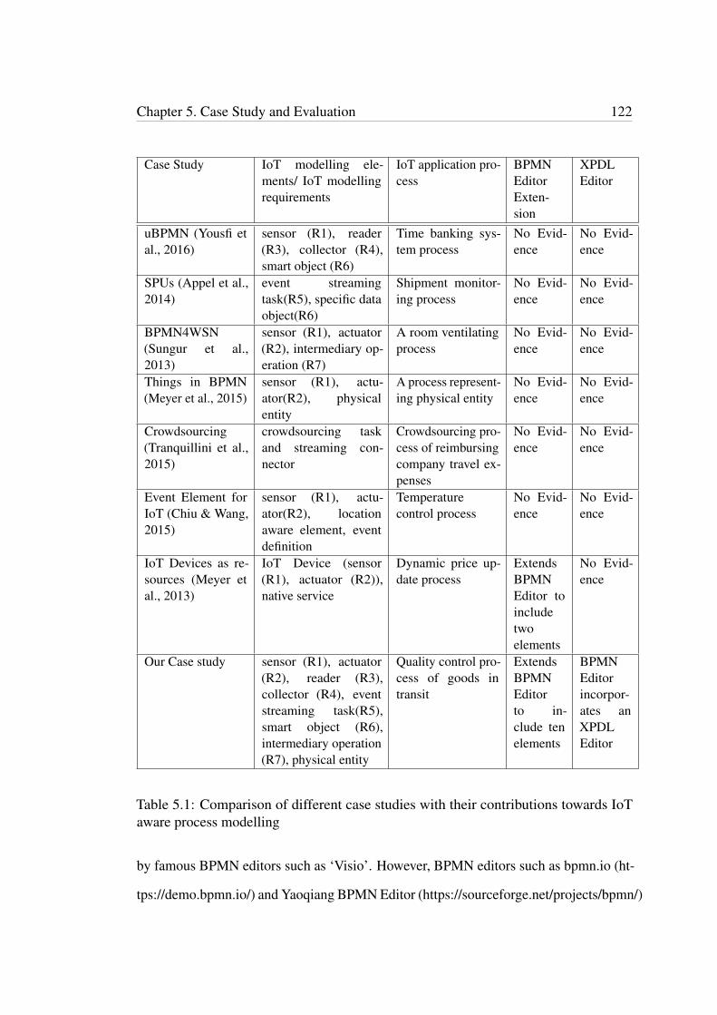
Chapter 5. Case Study and Evaluation 122
Case Study IoT modelling ele-ments/ IoT modellingrequirements
IoT application pro-cess
BPMNEditorExten-sion
XPDLEditor
uBPMN (Yousfi etal., 2016)
sensor (R1), reader(R3), collector (R4),smart object (R6)
Time banking sys-tem process
No Evid-ence
No Evid-ence
SPUs (Appel et al.,2014)
event streamingtask(R5), specific dataobject(R6)
Shipment monitor-ing process
No Evid-ence
No Evid-ence
BPMN4WSN(Sungur et al.,2013)
sensor (R1), actuator(R2), intermediary op-eration (R7)
A room ventilatingprocess
No Evid-ence
No Evid-ence
Things in BPMN(Meyer et al., 2015)
sensor (R1), actu-ator(R2), physicalentity
A process represent-ing physical entity
No Evid-ence
No Evid-ence
Crowdsourcing(Tranquillini et al.,2015)
crowdsourcing taskand streaming con-nector
Crowdsourcing pro-cess of reimbursingcompany travel ex-penses
No Evid-ence
No Evid-ence
Event Element forIoT (Chiu & Wang,2015)
sensor (R1), actu-ator(R2), locationaware element, eventdefinition
Temperaturecontrol process
No Evid-ence
No Evid-ence
IoT Devices as re-sources (Meyer etal., 2013)
IoT Device (sensor(R1), actuator (R2)),native service
Dynamic price up-date process
ExtendsBPMNEditor toincludetwoelements
No Evid-ence
Our Case study sensor (R1), actuator(R2), reader (R3),collector (R4), eventstreaming task(R5),smart object (R6),intermediary operation(R7), physical entity
Quality control pro-cess of goods intransit
ExtendsBPMNEditorto in-clude tenelements
BPMNEditorincorpor-ates anXPDLEditor
Table 5.1: Comparison of different case studies with their contributions towards IoTaware process modelling
by famous BPMN editors such as ‘Visio’. However, BPMN editors such as bpmn.io (ht-
tps://demo.bpmn.io/) and Yaoqiang BPMN Editor (https://sourceforge.net/projects/bpmn/)
Chapter 5. Case Study and Evaluation 123
use ‘bpmn’ file extension and their files are interchangeable. These files are written in
XML. Whereas, XPDL (XML Process Definition Language), (fileinfo.com, 2011) is con-
sidered to be the widely acceptable standard for storing and distributing BPMN diagrams
or the process definitions ((xpdl.org, 2018), (bizagi.com, 2018), (healthcareworkflow,
n.d.)). According to (Wang et al., 2006), XPDL is introduced as a common file inter-
change format for BPMN. Some BPMN editors such as bizagi (http://help.bizagi.com/process-
modeler/en/index.html?import_from_xpdl.htm) supports XPDL for importing and ex-
porting BPMN diagrams. In our system we import and export BPMN diagrams via
XPDL editor using XPDL coding. None of the above literature work has addressed
this area of storing and distributing BPMN files and none of them has implemented an
XPDL editor.
According to (Thakur, n.d.), feasibility is the evaluation of performance of a
software project or a tool. Feasibility of a software can be categorized in to three types in
general. They are economic feasibility, operational feasibility and technical feasibility.
From these three types, more relevant to our system is the operational feasibility.
Operational feasibility is that the software system should meet user requirements and
solve business problems. In evaluating our web based BPMN editor, we have shown
that this system meets user requirements as well as solve business problems. Technical
feasibility speaks about the technology in use and its underline resources such as
software and hardware of the system. Our BPMN editor is web based so that this can be
accessed merely with a PC and an internet connection. (Gediga, 2002) states usability
as the main evaluation criteria of a software system. Our web based BPMN editor
extension reflects this feature with its ease of use and error free properties.

Chapter 5. Case Study and Evaluation 124
5.4 Conclusion
In this chapter, we conducted a case study with the purpose of evaluating our IoT aware
web based BPMN and XPDL editor we introduced in the previous chapter. We took
a shipment control process of transporting perishable items as an IoT aware business
application scenario. We modelled this process with BPMN in our editor using the IoT
modelling elements we introduced to the editors toolkit. We illustrated this graphical
process and we provided the XPDL executable code generated of this process. We
further evaluated our editor tool by comparing with similar work.
Chapter 6
Conclusion
Internet of things is a rapidly evolving technology in the world today. It is not an
exaggeration to state that people and industry at large are already reaping the many
benefits it offers. We see it in use in everyday life. IoT covers vast range of applications
such as smart homes, smart cities, connected health, connected car, smart retail, etc.
When it comes to industrial applications, IoT technology is largely used in supply chain
management and agriculture, monitoring a product from its manufacturing stage to
distribution. Examples of some other industries with IoT applications are airline, health-
care, retailing, energy, pharmaceutical, insurance, media and entertainment. Companies
use business process models to depict their business processes making it efficient in
managing the activities in different applications. Business process management systems
are used to manage these applications. Modelling notations such as BPMN illustrates
the process models so that everyone involved in the business hierarchy would under-
stand the process. When IoT technology is involved in a certain business application,
there should be a way to integrate the IoT aspects in to the process model. This makes
it a necessity to investigate the methods to achieve this.
Therefore, this leads to finding out business process modelling requirements for IoT,
in other words, IoT modelling elements that can represent IoT aspects in a business
125

Chapter 6. Conclusion 126
process model. This motivated us in conducting this research and we came up with
seven requirements or IoT modelling elements for business process modelling for IoT.
This answers our first research question. We designed these elements by extending
BPMN 2.0. In answering our second question, this further motivated us to carry out
an implementation where, we practically extended a web based BPMN editor tool to
add these modelling elements. We have introduced ten IoT modelling elements into our
extended BPMN editor including physical entity as an IoT modelling element.We have
evaluated our work in a case study by modelling these IoT elements in an IoT related
business application process in BPMN and illustrating it by using our extended BPMN
editor. We also compared our work with similar work found in the literature.
6.1 Summary
Chapter one of this thesis contained the thesis introduction. We dedicated chapter two
for our literature review where we addressed the chosen literature work of past scholars,
which are relevant to our work. Even though we had already talked about IoT and BPM
in the introduction chapter, we tried to address these areas a little bit further in related to
our work. We described IoT, business process models and BPMN modelling frameworks
for IoT. In the summary sub section of the same section, we analysed and evaluated
each framework with IoT modelling elements they had introduced. In chapter three,
we tried to identify business process modelling requirements for IoT. We introduced a
problem scenario of an IoT related business process and derived those requirements. We
modelled this IoT application process by using BPMN 2.0, and used Visio modelling
tool for illustrating the model. This was a part of a supply chain management system
involving as many IoT modelling elements as it was possible to incorporate with it. We
took each element into account and did some intensive research in finding out different
categories and their features. We depicted those in diagrams including class diagrams

Chapter 6. Conclusion 127
wherever applicable. In chapter four, we designed the IoT modelling elements we had
found out as requirements for business process modelling, by extending BPMN 2.0.
Next, we carried out an implementation of practically extending a web based BPMN
and XPDL editor to facilitate adding those IoT modelling elements. In chapter, five we
carried out a case study to evaluate our IoT aware BPMN modelling tool. We modelled
an IoT related business process with BPMN, which comprised of the modelling elements
we introduced. The model was illustrated by using our extended BPMN editor tool,
which also generated XPDL code to store the model.
6.2 Limitations of the Research
We have extended BPMN 2.0 in proposing IoT modelling elements trying to adhere
with BPMN standards and referring to similar work. Yet, this model is not tested in
a practical environment to be certain that there are no consequences on the BPMN
standards due to these extensions. Moreover, we have not implemented our model in a
software system and carried out any testing. Due to the limited period of research, there
was not enough time to enhance these areas.
6.3 Recommendations and Further Study
Internet of Things is a vast subject area, which demands attention from researchers due
to its importance and usage in everyday life of people and businesses as a whole. Further
research on this area will only contribute to its growth and efficient use. Therefore, we
encourage further research on business process modelling for IoT mainly focussing on
illustrating IoT aspects of business application in process models. We did not find any
BPMN editor tool incorporated with IoT modelling elements available in the internet.
There are existing research in extending BPMN 2.0 for modelling IoT elements with
Chapter 6. Conclusion 128
business processes. Therefore, we suggest researchers to consider practically extending
BPMN modelling tools if possible and depict their models using their own tools. In
addition, the BPMN editor we have extended is available via GitHub as an open source
project so that anyone who would be interested in improving it further is encouraged
to do so. URL to the source code: https://github.com/pradeerat/IoT-aware-BPMN-
Editor. It is web based and is available free for modelling IoT aware business processes
using BPMN 2.0. URL to the website: https://pradeerat.github.io/IoT-aware-BPMN-
Editor/. This editor incorporates many if not all, important IoT modelling elements
as extensions to BPMN 2.0. We suggest people to use this for modelling IoT based
business applications as a start so that they can develop something better overcoming
any weakness in this.
6.4 Conclusion
Internet of Things technology promises a new and improved market domain for busi-
nesses while it tends to serve people better in the future. In IoT, internet combines real
world physical objects with the virtual world. In other words, IoT technology makes it
possible to connect physical entities via internet. This includes human beings, who are
connected through wearables with IoT aware features. This connection offers major
benefits to humans as well as businesses. It is going to reshape human activities as
well as the industry operations in a major way. Benefits to humans for example is that
a doctor can distantly monitor the health condition of a patient through a wearable
such as an IoT enabled wristwatch, when the patient is out of his home. One such
example, which benefits a business, would be to track a vehicle in a parking spot, which
did not make a payment. These two applications are examples of IoT aware business
applications. Organisations in managing their businesses use business process models in
illustrating their business processes. They use notations such as BPMN to model them
Chapter 6. Conclusion 129
so that everyone involved in the process from all hierarchical levels could understand it.
Unfortunately, not enough attention is given yet to integrate these IoT related business
applications in to business process models. In other words, business process modelling
for IoT aspects in business applications are not well supported by existing process
modelling notations. Therefore, it is a vital requirement to take necessary actions to
support reflect IoT aspects such as location awareness, sensing, reading and actuating
activities, etc. in business process models as we have addressed in our research.

References
Aberer, K., Hauswirth, M. & Salehi, A. (2006). Global sensor networks (Tech. Rep.).Aguilar-Saven, R. S. (2004). Business process modelling: Review and framework.
International Journal of production economics, 90(2), 129–149.Appel, S., Kleber, P., Frischbier, S., Freudenreich, T. & Buchmann, A. (2014). Modeling
and execution of event stream processing in business processes. InformationSystems, 46, 140–156.
atlasrfid.com. (2017). A question we are asked often: ’when is rfid better thanbarcodes?’ [Internet web page]. Retrieved from http://www.atlasrfid.com/jovix-education/auto-id-basics/rfid-vs-barcode/
azure.microsoft.com. (2017). What is middleware? [Internet web page].Retrieved from https://azure.microsoft.com/en-in/overview/what-is-middleware/
Barros, A., Gal, A. & Kindler, E. (2012). Business process management: 10th interna-tional conference, bpm 2012, tallinn, estonia, september 3-6, 2012, proceedings(Vol. 7481). Springer.
Biron, J. & Follett, J. (2016). The edge of the iot [Internet web page]. Retrieved fromhttps://www.oreilly.com/ideas/the-edge-of-the-iot
bizagi.com. (2018). Import diagram from xpdl [Internet web page].Retrieved from http://help.bizagi.com/process-modeler/en/index.html?import_from_xpdl.htm
bootcamplab.com. (2017). Sensor characteristics [Internet web page]. Retrieved fromhttps://www.bootcamplab.com/sensor-characteristics/
Center, F. N. R. (n.d.). Introduction to nfc [Internet web page]. Retrieved fromhttp://www.centrenational-rfid.com/introduction-to-nfc-article-132-gb-ruid-202.html
Chang, C., Srirama, S. N. & Buyya, R. (2015). Mobile cloud business processmanagement system for the internet of things: Review, challenges and blueprint.arXiv preprint arXiv:1512.07199.
Chiu, H.-H. & Wang, M.-S. (2015). Extending event elements of business processmodel for internet of things. In Computer and information technology; ubi-quitous computing and communications; dependable, autonomic and securecomputing; pervasive intelligence and computing (cit/iucc/dasc/picom), 2015ieee international conference on (pp. 783–788).
coep.vlab.co.in. (2011). Characterize the temperature sensor (rtd) [Internet web page].
130
References 131
Retrieved from http://coep.vlab.co.in/?sub=33&brch=91&sim=421&cnt=1
Dashevsky, E. (2014). Faq: How is lte-advanced different from regular lte?[Internet web page]. Retrieved from https://www.pcworld.com/article/2083981/faq-how-is-lte-advanced-different-from-regular-lte.html
Dumas, M., La Rosa, M., Mendling, J., Reijers, H. A. et al. (2013). Fundamentals ofbusiness process management (Vol. 1). Springer.
education.rec.ri.cmu.edu. (n.d.). What is a light sensor [Internet web page].Retrieved from http://education.rec.ri.cmu.edu/content/electronics/boe/light_sensor/1.html
fileinfo.com. (2011). .xpdl file extension [Internet web page]. Retrieved fromhttps://fileinfo.com/extension/xpdl
filext.com. (2018). .bpmn file [Internet web page]. Retrieved from http://filext.com/file-extension/BPMN
Gate, P. (2016). Iot (internet of things): A short series of observations [pt 1]:Introduction i& definition [Internet web page]. Retrieved from https://parasam.me/2016/05/19/iot-internet-of-things-a-short-series-of-observations-pt-1-introduction-definition/
Gediga, G. (2002). Evaluation of software systems [Internet web page].Retrieved from https://www.researchgate.net/publication/228721200_Evaluation_of_software_systems
Global, H. (2017). Hid global launches new indoor positioning services forworkforce optimization [Internet web page]. Retrieved from https://www.hidglobal.com/press-releases/hid-global-launches-new-indoor-positioning-services-workforce-optimization
Gonzalez, C. (2015). What’s the difference between pneumatic, hydraulic,and electrical actuators? [Internet web page]. Retrieved from http://www.machinedesign.com/linear-motion/what-s-difference-between-pneumatic-hydraulic-and-electrical-actuators
Goumopoulos, C., Kameas, A. & Hellas, P. (n.d.). Smart objects as components ofubicomp applications.
healthcareworkflow. (n.d.). Xpdl 2.2 bpmn 2.x and eclipse based editor.Holler, J., Tsiatsis, V., Mulligan, C., Avesand, S., Karnouskos, S. & Boyle, D. (2014).
From machine-to-machine to the internet of things: Introduction to a new age ofintelligence. Academic Press.
Howe, W. (2016). A brief history of the internet [Internet web page]. Retrieved fromhttp://www.walthowe.com/navnet/history.html
Huber, J., Fleck, N. & Ashby, M. (1997). The selection of mechanical actuatorsbased on performance indices. In Proceedings of the royal society of london a:Mathematical, physical and engineering sciences (Vol. 453, pp. 2185–2205).
investopedia.com. (n.d.). Business to business - b to b [Internet web page]. Retrievedfrom http://www.investopedia.com/terms/b/btob.aspl
References 132
Jeston, J., Nelis, J. & Davenport, T. (2008). Business process management: Prac-tical guidelines to successful implementations. 2008, nv. USA: Butterworth-Heinemann (Elsevier Ltd.).
Journal, R. (2017). Frequently asked questions [Internet web page]. Re-trieved from http://www.rfidjournal.com/site/faqs#Anchor-What-59125
Kalantar-Zadeh, K. (2013). Sensors: an introductory course. Springer Science &Business Media.
Kazuma Maekawa, e. a. (2017). Dynamic level-detecting characteristics ofexternal-heating-type mgb2 liquid hydrogen level sensors under liquid leveloscillation and its application to sloshing measurement [Internet web page].Retrieved from http://ieeexplore.ieee.org/stamp/stamp.jsp?arnumber=7792351&tag=1
Lee, I. & Lee, K. (2015). The internet of things (iot): Applications, investments, andchallenges for enterprises. Business Horizons, 58(4), 431–440.
List, B. & Korherr, B. (2006). An evaluation of conceptual business process modellinglanguages. In Proceedings of the 2006 acm symposium on applied computing (pp.1532–1539).
Mathas, C. (2012). Light sensors: An overview [Internet web page]. Re-trieved from https://www.digikey.com/en/articles/techzone/2012/sep/light-sensors-an-overview
May, S. (2017). Roku 3 review [Internet web page]. Retrieved fromhttp://www.techradar.com/reviews/audio-visual/av-accessories/roku-3-1203038/review
Meyer, S., Ruppen, A. & Hilty, L. (2015). The things of the internet of things in bpmn.In International conference on advanced information systems engineering (pp.285–297).
Meyer, S., Ruppen, A. & Magerkurth, C. (2013). Internet of things-aware processmodeling: integrating iot devices as business process resources. In Internationalconference on advanced information systems engineering (pp. 84–98).
Minihold, R. (2011). Near field communication (nfc) technology and measurements.White Paper, 6.
Model, B. P. (2011). Notation (bpmn) version 2.0. OMG Specification, ObjectManagement Group.
mpls.com. (n.d.). Iot - sensor and actuator [Internet web page]. Retrieved fromhttp://ip-mpls.com/iot-sensor-and-actuator/
NASA. (n.d.). Anatomy of an electromagnetic wave [Internet web page]. Retrievedfrom https://science.nasa.gov/ems/02_anatomy
O’Donnell, J. (2017). How smart sensors are transforming the internet of things[Internet web page]. Retrieved from http://internetofthingsagenda.techtarget.com/opinion/How-smart-sensors-are-transforming-the-Internet-of-Things
OMG. (2017). Object management group business process model and notation [Internetweb page]. Retrieved from http://www.bpmn.org/
References 133
OMRON. (2017). Proximity sensors [Internet web page]. Retrieved from https://www.ia.omron.com/support/guide/41/introduction.html
panasonic.biz. (n.d.). Introduction & features - pressure sensors [Internet web page].Retrieved from https://www3.panasonic.biz/ac/ae/service/tech_support/fasys/tech_guide/pressure/index.jsp
Parker, J. (2006). Sensor and actuator characteristics [Internet webpage]. Retrieved from http://www.crcnetbase.com/doi/pdfplus/10.1201/9781420037241.ch11
Rayes, A. & Samer, S. (2017). Internet of things—from hype to reality. Springer.Razzaque, M. A., Milojevic-Jevric, M., Palade, A. & Clarke, S. (2016). Middleware for
internet of things: a survey. IEEE Internet of Things Journal, 3(1), 70–95.redbeam.com. (2015). What’s the difference between barcode and rfid? [Inter-
net web page]. Retrieved from http://www.redbeam.com/rfid-vs-barcode/
Rouse, M. (2010). machine-to-machine (m2m) [Internet web page]. Re-trieved from http://internetofthingsagenda.techtarget.com/definition/machine-to-machine-M2M
Rouse, M. (2014). Bluetooth low energy (bluetooth le) [Internet web page]. Re-trieved from http://internetofthingsagenda.techtarget.com/definition/Bluetooth-Low-Energy-Bluetooth-LE
Rouse, M. (2015). Smart sensor [Internet web page]. Retrievedfrom http://internetofthingsagenda.techtarget.com/definition/smart-sensor
Rouse, M. (2017). Actuator [Internet web page]. Retrieved from http://internetofthingsagenda.techtarget.com/definition/actuator
shopify.co.nz. (n.d.). Business-to-consumer (b2c) [Internet web page]. Re-trieved from https://www.shopify.co.nz/encyclopedia/business-to-consumer-b2c
streetdirectory.com. (2017). Barcode scanners - types, features and benefits [Internetweb page]. Retrieved from http://www.streetdirectory.com/travel_guide/116493/hardware/barcode_scanners___types_features_and_benefits.html
Sun, C. (2012). Application of rfid technology for logistics on internet of things. AASRIProcedia, 1, 106–111.
Sungur, C. T., Spiess, P., Oertel, N. & Kopp, O. (2013). Extending bpmn for wirelesssensor networks. In Business informatics (cbi), 2013 ieee 15th conference on (pp.109–116).
TalTec. (2017). How a barcode reader works [Internet web page]. Retrievedfrom http://www.taltech.com/barcodesoftware/articles/how_barcode_reader_works
techopedia.com. (n.d.). Business to business to consumer (b2b2c) [Internet webpage]. Retrieved from https://www.techopedia.com/definition/23169/business-to-business-to-consumer-b2b2c
References 134
Thakur, D. (n.d.). What is feasibility study? types of feasibility. explain feasibility studyprocess [Internet web page]. Retrieved from http://ecomputernotes.com/software-engineering/feasibilitystudy
T.L.YeoT.SunK.T.V.Grattan. (2008). Fibre-optic sensor technologies forhumidity and moisture measurement [Internet web page]. Retrievedfrom http://www.sciencedirect.com/science/article/pii/S0924424708000836
Tracy, P. (2016). Many sensor types for the many iot use cases [Internet webpage]. Retrieved from https://www.rcrwireless.com/20161206/internet-of-things/sensor-iot-tag31-tag99
Tranquillini, S., Daniel, F., Kucherbaev, P. & Casati, F. (2015). Bpmn task instancestreaming for efficient micro-task crowdsourcing processes. In Internationalconference on business process management (pp. 333–349).
Tranquillini, S., Spieß, P., Daniel, F., Karnouskos, S., Casati, F., Oertel, N., . . . oth-ers (2012). Process-based design and integration of wireless sensor networkapplications. Business Process Management, 134–149.
tutorialspoint.com. (n.d.). Internet of things [Internet web page]. Retrieved fromhttps://www.tutorialspoint.com/internet_of_things/internet_of_things_tutorial.pdf
Van Der Aalst, W. M. (2013). Business process management: a comprehensive survey.ISRN Software Engineering, 2013.
Van Der Aalst, W. M., La Rosa, M. & Santoro, F. M. (2016). Business processmanagement. Springer.
Vladimer, M. (2015). Sensors, actuators and iot [Internet web page]. Retrieved fromhttps://www.linkedin.com/pulse/sensors-actuators-iot-mike-vladimer
Vyas, S. A. (2008). Light sensing robot [Internet web page]. Re-trieved from https://www.researchgate.net/publication/293825043_Light_Sensing_Robot
Wang, W., Ding, H., Dong, J. & Ren, C. (2006). A comparison of business processmodeling methods. In Service operations and logistics, and informatics, 2006.soli’06. ieee international conference on (pp. 1136–1141).
wdc65xx.com. (2016). What are actuators and different types of actuators? [Internetweb page]. Retrieved from http://wdc65xx.com/lessons/what-are-actuators-and-different-types-of-actuators/
wdc65xx.com. (2017). Types of actuators and their applications and uses [Internetweb page]. Retrieved from http://www.thomasnet.com/articles/pumps-valves-accessories/types-of-actuators
Weekly, E. (n.d.). Energy-efficient wireless protocols for wearables [Internet webpage]. Retrieved from https://www.electronicsweekly.com/market-sectors/embedded-systems/energy-efficient-wireless-protocols-wearables-2014-08/
Weske, M. (2010). Business process management: concepts, languages, architectures.Springer Publishing Company, Incorporated.
References 135
Weske, M. (2012). Business process management architectures. In Business processmanagement (pp. 333–371). Springer.
WIKIDEDIA. (2017). Business process model and notation [Internet webpage]. Retrieved from https://en.wikipedia.org/wiki/Business_Process_Model_and_Notation
wikipedia. (2017). Proximity sensor [Internet web page]. Retrieved from https://en.wikipedia.org/wiki/Proximity_sensor
wikipedia.org. (2017). Actuator [Internet web page]. Retrieved from https://en.wikipedia.org/wiki/Actuator
Woodford, C. (2016). Barcodes and barcode scanners [Internet webpage]. Retrieved from http://www.explainthatstuff.com/barcodescanners.html
xpdl.org. (2018). Xml process definition language (xpdl) [Internet web page]. Retrievedfrom http://www.xpdl.org/
Yamazoe, N. & Shimizu, Y. (1986). Humidity sensors: principles and applications.Sensors and Actuators, 10(3-4), 379–398.
Yao, J. (2017). Function and characteristics of photoelectric liquid level sensor[Internet web page]. Retrieved from https://www.linkedin.com/pulse/function-characteristics-photoelectric-liquid-level-sensor-yao
Yousfi, A., de Freitas, A., Dey, A. K. & Saidi, R. (2016). The use of ubiquitouscomputing for business process improvement. IEEE Transactions on ServicesComputing, 9(4), 621–632.
Zancul, E. d. S., Takey, S. M., Barquet, A. P. B., Kuwabara, L. H., Cauchick Miguel,P. A. & Rozenfeld, H. (2016). Business process support for iot based product-service systems (pss). Business Process Management Journal, 22(2), 305–323.
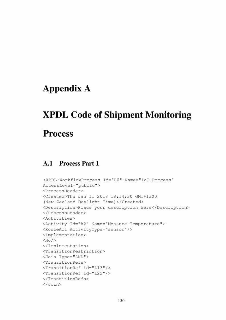
Appendix A
XPDL Code of Shipment Monitoring
Process
A.1 Process Part 1
<XPDL:WorkflowProcess Id="P0" Name="IoT Process"AccessLevel="public"><ProcessHeader><Created>Thu Jan 11 2018 18:14:30 GMT+1300(New Zealand Daylight Time)</Created><Description>Place your description here</Description></ProcessHeader><Activities><Activity Id="A2" Name="Measure Temperature"><RouteAct ActivityType="sensor"/><Implementation><No/></Implementation><TransitionRestriction><Join Type="AND"><TransitionRefs><TransitionRef id="L13"/><TransitionRef id="L22"/></TransitionRefs></Join>
136
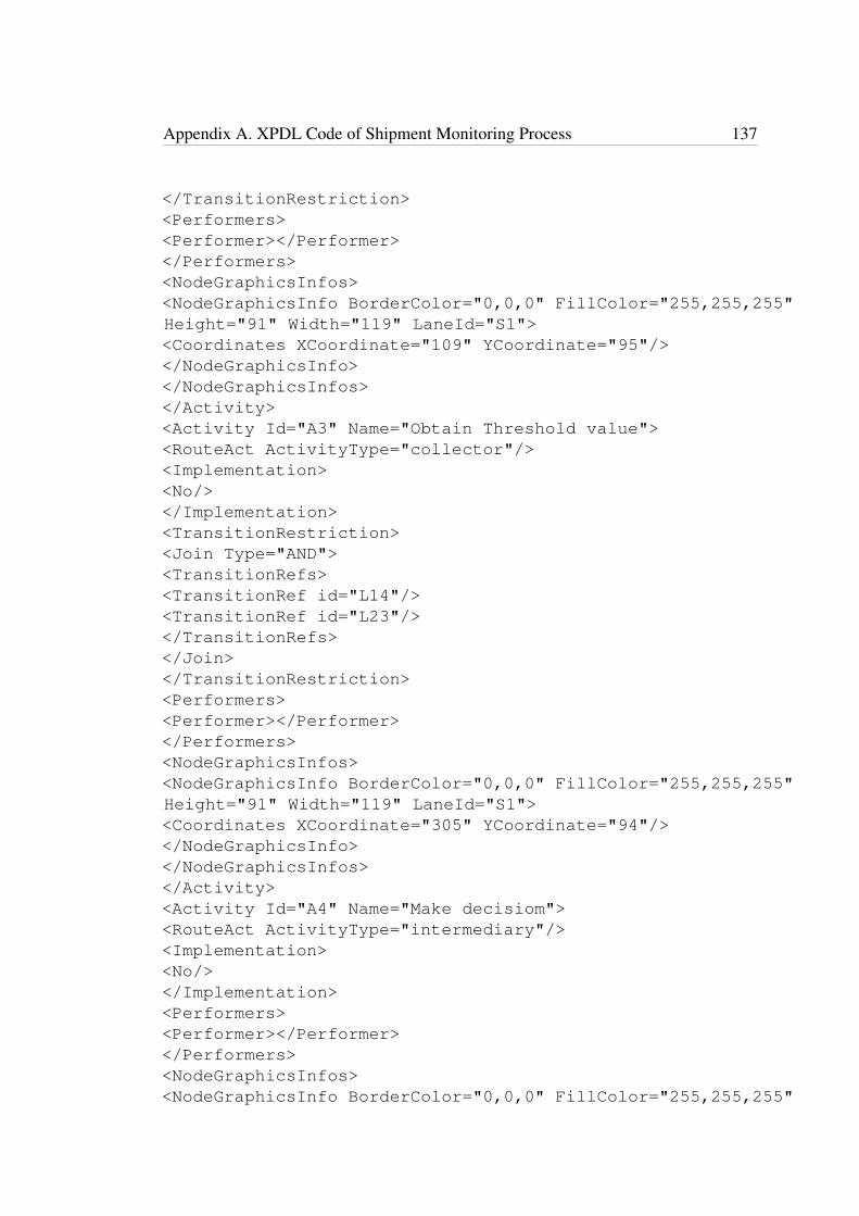
Appendix A. XPDL Code of Shipment Monitoring Process 137
</TransitionRestriction><Performers><Performer></Performer></Performers><NodeGraphicsInfos><NodeGraphicsInfo BorderColor="0,0,0" FillColor="255,255,255"Height="91" Width="119" LaneId="S1"><Coordinates XCoordinate="109" YCoordinate="95"/></NodeGraphicsInfo></NodeGraphicsInfos></Activity><Activity Id="A3" Name="Obtain Threshold value"><RouteAct ActivityType="collector"/><Implementation><No/></Implementation><TransitionRestriction><Join Type="AND"><TransitionRefs><TransitionRef id="L14"/><TransitionRef id="L23"/></TransitionRefs></Join></TransitionRestriction><Performers><Performer></Performer></Performers><NodeGraphicsInfos><NodeGraphicsInfo BorderColor="0,0,0" FillColor="255,255,255"Height="91" Width="119" LaneId="S1"><Coordinates XCoordinate="305" YCoordinate="94"/></NodeGraphicsInfo></NodeGraphicsInfos></Activity><Activity Id="A4" Name="Make decisiom"><RouteAct ActivityType="intermediary"/><Implementation><No/></Implementation><Performers><Performer></Performer></Performers><NodeGraphicsInfos><NodeGraphicsInfo BorderColor="0,0,0" FillColor="255,255,255"

Appendix A. XPDL Code of Shipment Monitoring Process 138
Height="91" Width="119" LaneId="S1"><Coordinates XCoordinate="508" YCoordinate="95"/></NodeGraphicsInfo></NodeGraphicsInfos></Activity><Activity Id="A5" Name="Increase Temperature"><RouteAct ActivityType="reader"/><Implementation><No/></Implementation><Performers><Performer></Performer></Performers><NodeGraphicsInfos><NodeGraphicsInfo BorderColor="0,0,0" FillColor="255,255,255"Height="91" Width="119" LaneId="S1"><Coordinates XCoordinate="884" YCoordinate="6"/></NodeGraphicsInfo></NodeGraphicsInfos></Activity><Activity Id="A6" Name="Reduce Temperature"><RouteAct ActivityType="reader"/><Implementation><No/></Implementation><Performers><Performer></Performer></Performers><NodeGraphicsInfos><NodeGraphicsInfo BorderColor="0,0,0" FillColor="255,255,255"Height="91" Width="119" LaneId="S1"><Coordinates XCoordinate="890" YCoordinate="185"/></NodeGraphicsInfo></NodeGraphicsInfos></Activity><Activity Id="E7"><Event><XPDL:Start Trigger="None"/></Event><NodeGraphicsInfos><NodeGraphicsInfo BorderColor="0,0,0" FillColor="255,255,255"Height="42" Width="41" LaneId="S1"><Coordinates XCoordinate="9" YCoordinate="120"/></NodeGraphicsInfo>

Appendix A. XPDL Code of Shipment Monitoring Process 139
</NodeGraphicsInfos></Activity><Activity Id="E8"><Event><XPDL:Terminate Trigger="None"/></Event><NodeGraphicsInfos><NodeGraphicsInfo BorderColor="0,0,0" FillColor="255,255,255"Height="42" Width="41" LaneId="S1"><Coordinates XCoordinate="1243" YCoordinate="112"/></NodeGraphicsInfo></NodeGraphicsInfos></Activity><Activity Id="G9"><Route GatewayType="XOR_Data"/><TransitionRestrictions><TransitionRestriction><Split Type="XOR_Data"><TransitionRefs><TransitionRef id="L17"/><TransitionRef id="L18"/></TransitionRefs></Split></TransitionRestriction></TransitionRestrictions><NodeGraphicsInfos><NodeGraphicsInfo BorderColor="0,0,0" FillColor="255,255,255"Height="40" Width="40" LaneId="S1"><Coordinates XCoordinate="700" YCoordinate="122"/></NodeGraphicsInfo></NodeGraphicsInfos></Activity><Activity Id="G10"><Route GatewayType="XOR_Data"/><TransitionRestrictions><TransitionRestriction><Join Type="XOR_Data"><TransitionRefs><TransitionRef id="L19"/><TransitionRef id="L20"/></TransitionRefs></Join></TransitionRestriction></TransitionRestrictions>
Appendix A. XPDL Code of Shipment Monitoring Process 140
<NodeGraphicsInfos><NodeGraphicsInfo BorderColor="0,0,0" FillColor="255,255,255"Height="40" Width="40" LaneId="S1"><Coordinates XCoordinate="1137" YCoordinate="113"/></NodeGraphicsInfo></NodeGraphicsInfos></Activity><Activity Id="D11" Name=""><RouteData DataType="Database"/><Implementation><No/></Implementation><TransitionRestriction><Split Type="AND"><TransitionRefs><TransitionRef id="L23"/></TransitionRefs></Split></TransitionRestriction><Performers><Performer></Performer></Performers><NodeGraphicsInfos><NodeGraphicsInfo BorderColor="0,0,0" FillColor="255,255,255"Height="65" Width="50" LaneId="S1"><Coordinates XCoordinate="363" YCoordinate="297"/></NodeGraphicsInfo></NodeGraphicsInfos></Activity><Activity Id="D12" Name="Perishable Goods"><RouteData DataType="PhysicalEntity"/><Implementation><No/></Implementation><TransitionRestriction><Split Type="AND"><TransitionRefs><TransitionRef id="L22"/></TransitionRefs></Split></TransitionRestriction><Performers><Performer></Performer></Performers>
Appendix A. XPDL Code of Shipment Monitoring Process 141
<NodeGraphicsInfos><NodeGraphicsInfo BorderColor="0,0,0" FillColor="255,255,255"Height="65" Width="50" LaneId="S1"><Coordinates XCoordinate="114" YCoordinate="293"/></NodeGraphicsInfo></NodeGraphicsInfos></Activity></Activities><Transitions><Transition Name="" From="E7" Id="L13" To="A2"><Condition Type="Normal Sequence"/><ConnectorGraphicsInfos><ConnectorGraphicsInfo FillColor="0,0,0"Style="No_Routing_Splines"/></ConnectorGraphicsInfos></Transition><Transition Name="" From="A2" Id="L14" To="A3"><Condition Type="Normal Sequence"/><ConnectorGraphicsInfos><ConnectorGraphicsInfo FillColor="0,0,0"Style="No_Routing_Splines"/></ConnectorGraphicsInfos></Transition><Transition Name="" From="A3" Id="L15" To="A4"><Condition Type="Normal Sequence"/><ConnectorGraphicsInfos><ConnectorGraphicsInfo FillColor="0,0,0"Style="No_Routing_Splines"/></ConnectorGraphicsInfos></Transition><Transition Name="" From="A4" Id="L16" To="G9"><Condition Type="Normal Sequence"/><ConnectorGraphicsInfos><ConnectorGraphicsInfo FillColor="0,0,0"Style="No_Routing_Splines"/></ConnectorGraphicsInfos></Transition><Transition Name="Temperature < Threshold value" From="G9"Id="L17" To="A5"><Condition Type="Normal Sequence"/><ConnectorGraphicsInfos><ConnectorGraphicsInfo FillColor="0,0,0"Style="No_Routing_Splines"/></ConnectorGraphicsInfos>
Appendix A. XPDL Code of Shipment Monitoring Process 142
</Transition><Transition Name="Temperature > Threshold value" From="G9"Id="L18" To="A6"><Condition Type="Normal Sequence"/><ConnectorGraphicsInfos><ConnectorGraphicsInfo FillColor="0,0,0"Style="No_Routing_Splines"/></ConnectorGraphicsInfos></Transition><Transition Name="" From="A5" Id="L19" To="G10"><Condition Type="Normal Sequence"/><ConnectorGraphicsInfos><ConnectorGraphicsInfo FillColor="0,0,0"Style="No_Routing_Splines"/></ConnectorGraphicsInfos></Transition><Transition Name="" From="A6" Id="L20" To="G10"><Condition Type="Normal Sequence"/><ConnectorGraphicsInfos><ConnectorGraphicsInfo FillColor="0,0,0"Style="No_Routing_Splines"/></ConnectorGraphicsInfos></Transition><Transition Name="" From="G10" Id="L21" To="E8"><Condition Type="Normal Sequence"/><ConnectorGraphicsInfos><ConnectorGraphicsInfo FillColor="0,0,0"Style="No_Routing_Splines"/></ConnectorGraphicsInfos></Transition><Transition Name="" From="D12" Id="L22" To="A2"><Condition Type="AssociationW"/><ConnectorGraphicsInfos><ConnectorGraphicsInfo FillColor="0,0,0"Style="No_Routing_Splines"/></ConnectorGraphicsInfos></Transition><Transition Name="Threshold value" From="D11" Id="L23" To="A3"><Condition Type="Association"/><ConnectorGraphicsInfos><ConnectorGraphicsInfo FillColor="0,0,0"Style="No_Routing_Splines"/></ConnectorGraphicsInfos></Transition>
Appendix A. XPDL Code of Shipment Monitoring Process 143
</Transitions></XPDL:WorkflowProcess>
A.2 Process Part 2<XPDL:WorkflowProcess Id="P0" Name="IoT Process"AccessLevel="public"><ProcessHeader><Created>Thu Jan 11 2018 18:49:15 GMT+1300(New Zealand Daylight Time)</Created><Description>Place your description here</Description></ProcessHeader><Activities><Activity Id="E2"><Event><XPDL:Start Trigger="None"/></Event><NodeGraphicsInfos><NodeGraphicsInfo BorderColor="0,0,0" FillColor="255,255,255"Height="42" Width="41" LaneId="S1"><Coordinates XCoordinate="8" YCoordinate="68"/></NodeGraphicsInfo></NodeGraphicsInfos></Activity><Activity Id="E3"><Event><XPDL:Terminate Trigger="None"/></Event><NodeGraphicsInfos><NodeGraphicsInfo BorderColor="0,0,0" FillColor="255,255,255"Height="42" Width="41" LaneId="S1"><Coordinates XCoordinate="1265" YCoordinate="226"/></NodeGraphicsInfo></NodeGraphicsInfos></Activity><Activity Id="A4" Name="Monitor goods in transit"><RouteAct ActivityType="process"/><Implementation><No/></Implementation><Performers><Performer></Performer></Performers>
Appendix A. XPDL Code of Shipment Monitoring Process 144
<NodeGraphicsInfos><NodeGraphicsInfo BorderColor="0,0,0" FillColor="255,255,255"Height="91" Width="119" LaneId="S1"><Coordinates XCoordinate="101" YCoordinate="44"/></NodeGraphicsInfo></NodeGraphicsInfos></Activity><Activity Id="A5" Name="Obtain current coordinates"><RouteAct ActivityType="reader"/><Implementation><No/></Implementation><TransitionRestriction><Join Type="AND"><TransitionRefs><TransitionRef id="L14"/><TransitionRef id="L27"/></TransitionRefs></Join></TransitionRestriction><Performers><Performer></Performer></Performers><NodeGraphicsInfos><NodeGraphicsInfo BorderColor="0,0,0" FillColor="255,255,255"Height="91" Width="119" LaneId="S1"><Coordinates XCoordinate="277" YCoordinate="43"/></NodeGraphicsInfo></NodeGraphicsInfos></Activity><Activity Id="A6" Name="Inform location"><RouteAct ActivityType="subProcess"/><Implementation><No/></Implementation><Performers><Performer></Performer></Performers><NodeGraphicsInfos><NodeGraphicsInfo BorderColor="0,0,0" FillColor="255,255,255"Height="91" Width="119" LaneId="S1"><Coordinates XCoordinate="460" YCoordinate="42"/></NodeGraphicsInfo></NodeGraphicsInfos>
Appendix A. XPDL Code of Shipment Monitoring Process 145
</Activity><Activity Id="A7" Name="Check for environmental conditions"><RouteAct ActivityType="eventstreams"/><Implementation><No/></Implementation><TransitionRestriction><Join Type="AND"><TransitionRefs><TransitionRef id="L16"/><TransitionRef id="L28"/></TransitionRefs></Join></TransitionRestriction><Performers><Performer></Performer></Performers><NodeGraphicsInfos><NodeGraphicsInfo BorderColor="0,0,0" FillColor="255,255,255"Height="91" Width="119" LaneId="S1"><Coordinates XCoordinate="461" YCoordinate="207"/></NodeGraphicsInfo></NodeGraphicsInfos></Activity><Activity Id="A8" Name="Report violation"><RouteAct ActivityType="eventstreams"/><Implementation><No/></Implementation><TransitionRestriction><Join Type="AND"><TransitionRefs><TransitionRef id="L18"/><TransitionRef id="L29"/></TransitionRefs></Join></TransitionRestriction><Performers><Performer></Performer></Performers><NodeGraphicsInfos><NodeGraphicsInfo BorderColor="0,0,0" FillColor="255,255,255"Height="91" Width="119" LaneId="S1"><Coordinates XCoordinate="838" YCoordinate="134"/>
Appendix A. XPDL Code of Shipment Monitoring Process 146
</NodeGraphicsInfo></NodeGraphicsInfos></Activity><Activity Id="A9" Name="Continue delivery"><RouteAct ActivityType="eventstreams"/><Implementation><No/></Implementation><Performers><Performer></Performer></Performers><NodeGraphicsInfos><NodeGraphicsInfo BorderColor="0,0,0" FillColor="255,255,255"Height="91" Width="119" LaneId="S1"><Coordinates XCoordinate="841" YCoordinate="275"/></NodeGraphicsInfo></NodeGraphicsInfos></Activity><Activity Id="A10" Name="Cancel Delivery"><RouteAct ActivityType="process"/><Implementation><No/></Implementation><Performers><Performer></Performer></Performers><NodeGraphicsInfos><NodeGraphicsInfo BorderColor="0,0,0" FillColor="255,255,255"Height="91" Width="119" LaneId="S1"><Coordinates XCoordinate="1022" YCoordinate="133"/></NodeGraphicsInfo></NodeGraphicsInfos></Activity><Activity Id="G11"><Route GatewayType="XOR_Data"/><TransitionRestrictions><TransitionRestriction><Split Type="XOR_Data"><TransitionRefs><TransitionRef id="L18"/><TransitionRef id="L19"/></TransitionRefs></Split></TransitionRestriction>

Appendix A. XPDL Code of Shipment Monitoring Process 147
</TransitionRestrictions><NodeGraphicsInfos><NodeGraphicsInfo BorderColor="0,0,0" FillColor="255,255,255"Height="40" Width="40" LaneId="S1"><Coordinates XCoordinate="669" YCoordinate="233"/></NodeGraphicsInfo></NodeGraphicsInfos></Activity><Activity Id="G12"><Route GatewayType="XOR_Data"/><TransitionRestrictions><TransitionRestriction><Join Type="XOR_Data"><TransitionRefs><TransitionRef id="L21"/><TransitionRef id="L22"/></TransitionRefs></Join></TransitionRestriction></TransitionRestrictions><NodeGraphicsInfos><NodeGraphicsInfo BorderColor="0,0,0" FillColor="255,255,255"Height="40" Width="40" LaneId="S1"><Coordinates XCoordinate="1183" YCoordinate="227"/></NodeGraphicsInfo></NodeGraphicsInfos></Activity><Activity Id="D24" Name=""><RouteData DataType="InputEvent"/><Implementation><No/></Implementation><TransitionRestriction><Split Type="AND"><TransitionRefs><TransitionRef id="L29"/></TransitionRefs></Split></TransitionRestriction><Performers><Performer></Performer></Performers><NodeGraphicsInfos><NodeGraphicsInfo BorderColor="0,0,0" FillColor="255,255,255"
Appendix A. XPDL Code of Shipment Monitoring Process 148
Height="65" Width="50" LaneId="S1"><Coordinates XCoordinate="635" YCoordinate="16"/></NodeGraphicsInfo></NodeGraphicsInfos></Activity><Activity Id="D25" Name="Monitoring events"><RouteData DataType="InputEvent"/><Implementation><No/></Implementation><TransitionRestriction><Split Type="AND"><TransitionRefs><TransitionRef id="L28"/></TransitionRefs></Split></TransitionRestriction><Performers><Performer></Performer></Performers><NodeGraphicsInfos><NodeGraphicsInfo BorderColor="0,0,0" FillColor="255,255,255"Height="65" Width="50" LaneId="S1"><Coordinates XCoordinate="369" YCoordinate="294"/></NodeGraphicsInfo></NodeGraphicsInfos></Activity><Activity Id="D26" Name="GPS Satellite"><RouteData DataType="SmartObject"/><Implementation><No/></Implementation><TransitionRestriction><Split Type="AND"><TransitionRefs><TransitionRef id="L27"/></TransitionRefs></Split></TransitionRestriction><Performers><Performer></Performer></Performers><NodeGraphicsInfos><NodeGraphicsInfo BorderColor="0,0,0" FillColor="255,255,255"
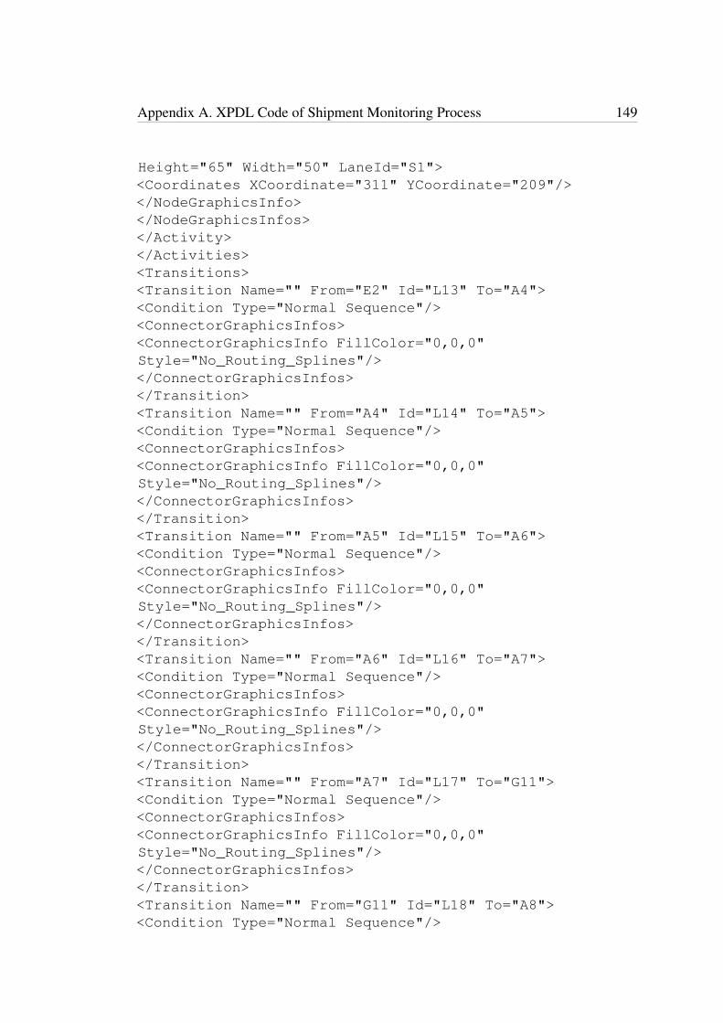
Appendix A. XPDL Code of Shipment Monitoring Process 149
Height="65" Width="50" LaneId="S1"><Coordinates XCoordinate="311" YCoordinate="209"/></NodeGraphicsInfo></NodeGraphicsInfos></Activity></Activities><Transitions><Transition Name="" From="E2" Id="L13" To="A4"><Condition Type="Normal Sequence"/><ConnectorGraphicsInfos><ConnectorGraphicsInfo FillColor="0,0,0"Style="No_Routing_Splines"/></ConnectorGraphicsInfos></Transition><Transition Name="" From="A4" Id="L14" To="A5"><Condition Type="Normal Sequence"/><ConnectorGraphicsInfos><ConnectorGraphicsInfo FillColor="0,0,0"Style="No_Routing_Splines"/></ConnectorGraphicsInfos></Transition><Transition Name="" From="A5" Id="L15" To="A6"><Condition Type="Normal Sequence"/><ConnectorGraphicsInfos><ConnectorGraphicsInfo FillColor="0,0,0"Style="No_Routing_Splines"/></ConnectorGraphicsInfos></Transition><Transition Name="" From="A6" Id="L16" To="A7"><Condition Type="Normal Sequence"/><ConnectorGraphicsInfos><ConnectorGraphicsInfo FillColor="0,0,0"Style="No_Routing_Splines"/></ConnectorGraphicsInfos></Transition><Transition Name="" From="A7" Id="L17" To="G11"><Condition Type="Normal Sequence"/><ConnectorGraphicsInfos><ConnectorGraphicsInfo FillColor="0,0,0"Style="No_Routing_Splines"/></ConnectorGraphicsInfos></Transition><Transition Name="" From="G11" Id="L18" To="A8"><Condition Type="Normal Sequence"/>
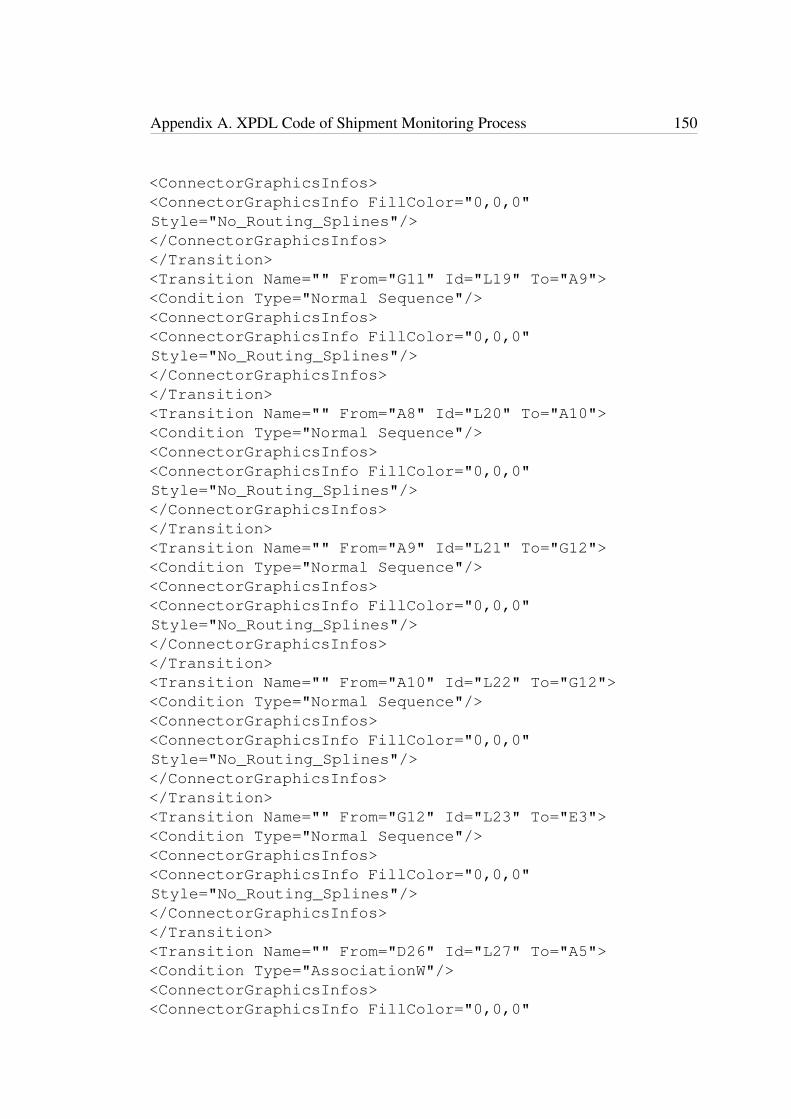
Appendix A. XPDL Code of Shipment Monitoring Process 150
<ConnectorGraphicsInfos><ConnectorGraphicsInfo FillColor="0,0,0"Style="No_Routing_Splines"/></ConnectorGraphicsInfos></Transition><Transition Name="" From="G11" Id="L19" To="A9"><Condition Type="Normal Sequence"/><ConnectorGraphicsInfos><ConnectorGraphicsInfo FillColor="0,0,0"Style="No_Routing_Splines"/></ConnectorGraphicsInfos></Transition><Transition Name="" From="A8" Id="L20" To="A10"><Condition Type="Normal Sequence"/><ConnectorGraphicsInfos><ConnectorGraphicsInfo FillColor="0,0,0"Style="No_Routing_Splines"/></ConnectorGraphicsInfos></Transition><Transition Name="" From="A9" Id="L21" To="G12"><Condition Type="Normal Sequence"/><ConnectorGraphicsInfos><ConnectorGraphicsInfo FillColor="0,0,0"Style="No_Routing_Splines"/></ConnectorGraphicsInfos></Transition><Transition Name="" From="A10" Id="L22" To="G12"><Condition Type="Normal Sequence"/><ConnectorGraphicsInfos><ConnectorGraphicsInfo FillColor="0,0,0"Style="No_Routing_Splines"/></ConnectorGraphicsInfos></Transition><Transition Name="" From="G12" Id="L23" To="E3"><Condition Type="Normal Sequence"/><ConnectorGraphicsInfos><ConnectorGraphicsInfo FillColor="0,0,0"Style="No_Routing_Splines"/></ConnectorGraphicsInfos></Transition><Transition Name="" From="D26" Id="L27" To="A5"><Condition Type="AssociationW"/><ConnectorGraphicsInfos><ConnectorGraphicsInfo FillColor="0,0,0"
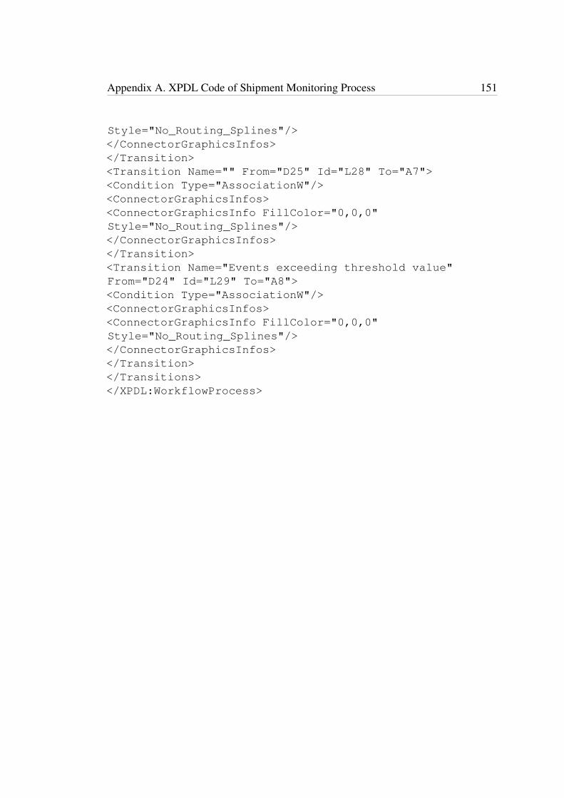
Appendix A. XPDL Code of Shipment Monitoring Process 151
Style="No_Routing_Splines"/></ConnectorGraphicsInfos></Transition><Transition Name="" From="D25" Id="L28" To="A7"><Condition Type="AssociationW"/><ConnectorGraphicsInfos><ConnectorGraphicsInfo FillColor="0,0,0"Style="No_Routing_Splines"/></ConnectorGraphicsInfos></Transition><Transition Name="Events exceeding threshold value"From="D24" Id="L29" To="A8"><Condition Type="AssociationW"/><ConnectorGraphicsInfos><ConnectorGraphicsInfo FillColor="0,0,0"Style="No_Routing_Splines"/></ConnectorGraphicsInfos></Transition></Transitions></XPDL:WorkflowProcess>

Appendix B
Instructions to use IoT aware BPMN
and XPDL Editor
B.1 Steps to use IoT aware BPMN and XPDL Editor
• The left side toolbox consists of the tabs, Swimlanes , Activities, Events, Gate-
ways, Connectors, Data and Artifacts.
• To open any tab in that toolbox, click on the required tab once.
• To start drawing a diagram, select a single lane or multiple lane pool (depending
on the requirement) from the Swimlanes tab of the toolbox by clicking on the
particular pool icon once. This will make it appear on the editor/ editing space at
the right side. Figure B.1 illustrates this.
• If you want to place a start Event on the pool for example, move the cursor to that
element, drag, and drop it on the pool on the editor as shown in Figure B.2. The
same steps should be followed for elements under Activities, Gateways and Data
and Artifacts.
152
Appendix B. Instructions to use IoT aware BPMN and XPDL Editor 153
• You can adjust the positon of these elements in the pool by dragging and moving
to replace them on the pool.
• Now, if you want to connect a ‘sensing task’ for example with the start event,
place the element on the pool following above steps and connect each other by
using a connector under ‘Connectors’ from the toolbox.
• For this, click on the particular connector icon and it will be highlighted. The
cursor icon will turn to “+”sign. When you move the cursor to each element, their
colour will change to ‘yellow’. Now when you click on one element and drag the
cursor to the other, the two elements will get connected by the chosen connector.
Figure B.3 shows this.
• To deselect the chosen connector you need to click on it again at the toolbox so
that the highlighting disappear. If you do not remove the selection, you cannot
move any element on the pool in the editor.
• An element cannot be removed while a connector is chosen and being highlighted.
• To remove an element from the diagram, deselect any connector selections as
already mentioned. Right click on the element you want to delete and this will
bring a popup menu with ‘Delete’ as an option in it. When you select delete
option, this will delete the element as well as any associations it has.
• To add text to any element, for example to add text to ‘sensing task’ from
‘Activities’ as shown in Figure B.4, double click on the element and a text area
window will appear on screen. Type text and click on the button ‘Set’. Click
on ‘Cancel’ button to discard the text. Same steps to be followed in editing any
written text on an object.
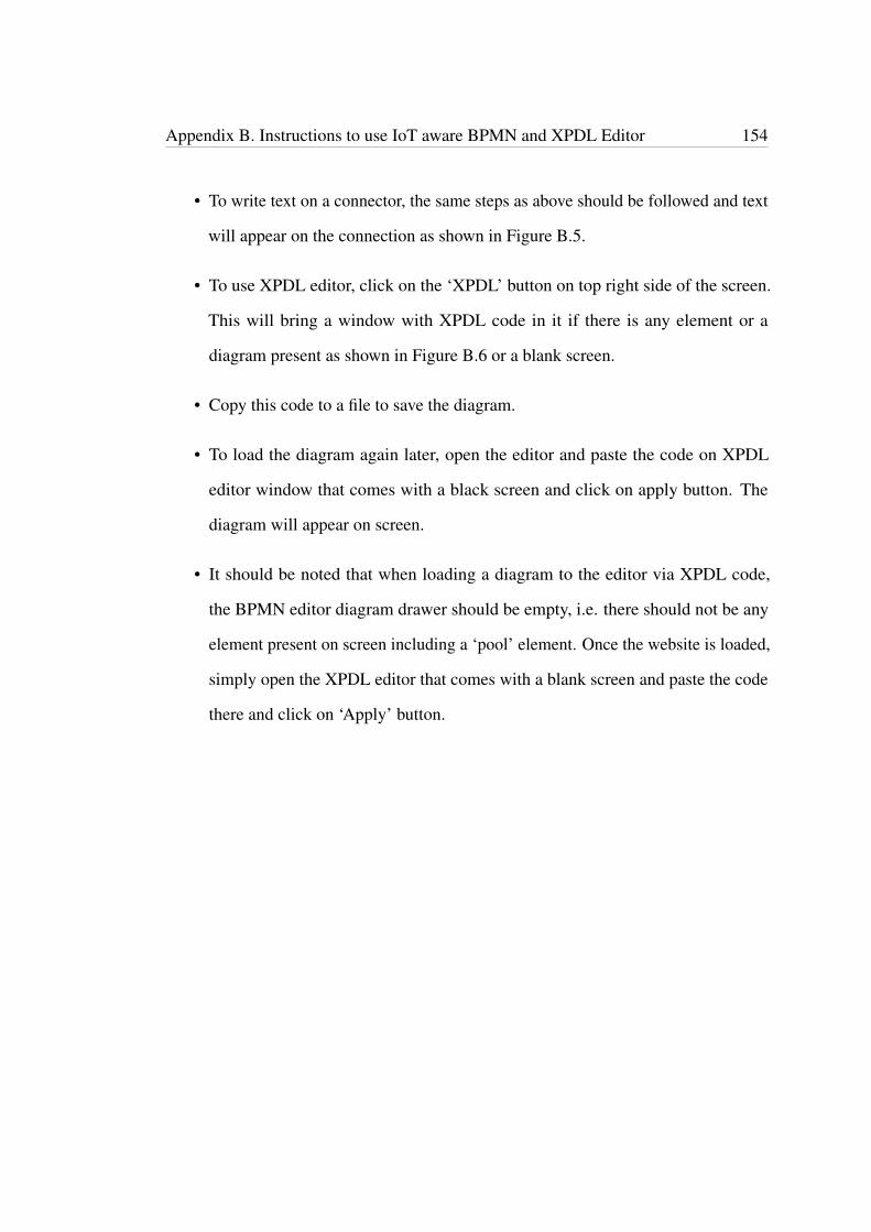
Appendix B. Instructions to use IoT aware BPMN and XPDL Editor 154
• To write text on a connector, the same steps as above should be followed and text
will appear on the connection as shown in Figure B.5.
• To use XPDL editor, click on the ‘XPDL’ button on top right side of the screen.
This will bring a window with XPDL code in it if there is any element or a
diagram present as shown in Figure B.6 or a blank screen.
• Copy this code to a file to save the diagram.
• To load the diagram again later, open the editor and paste the code on XPDL
editor window that comes with a black screen and click on apply button. The
diagram will appear on screen.
• It should be noted that when loading a diagram to the editor via XPDL code,
the BPMN editor diagram drawer should be empty, i.e. there should not be any
element present on screen including a ‘pool’ element. Once the website is loaded,
simply open the XPDL editor that comes with a blank screen and paste the code
there and click on ‘Apply’ button.

Appendix B. Instructions to use IoT aware BPMN and XPDL Editor 155
Figure B.1: BPMN and XPDL Editor with a pool
Figure B.2: BPMN and XPDL Editor, a start event placed on pool
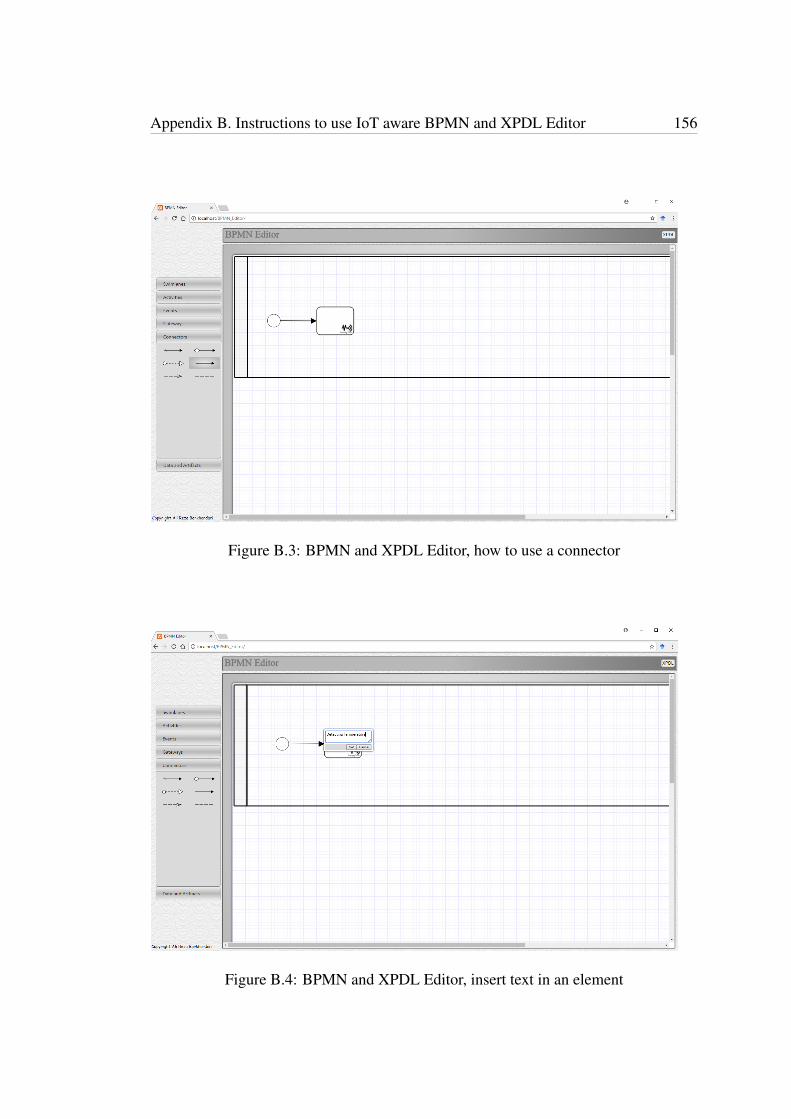
Appendix B. Instructions to use IoT aware BPMN and XPDL Editor 156
Figure B.3: BPMN and XPDL Editor, how to use a connector
Figure B.4: BPMN and XPDL Editor, insert text in an element
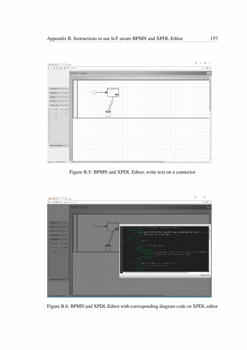
Appendix B. Instructions to use IoT aware BPMN and XPDL Editor 157
Figure B.5: BPMN and XPDL Editor, write text on a connector
Figure B.6: BPMN and XPDL Editor with corresponding diagram code on XPDL editor