butler xt2 - traxon technologies€¦ · connecting more than one butler xt2 ... >= 1.4 a always...
TRANSCRIPT
Butler XT2Setup Manual
Butler XT2 Setup ManualEdition/Ausgabe: 23.12.2016 Published by/Herausgegeben von:
OSRAM GmbH BU Lighting Solutions Karl Schurz-Strasse 38 Paderborn, Germany ©2016, OSRAM GmbH All rights reserved/Alle Rechte vorbehalten
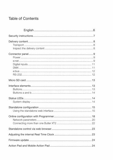
Table of Contents
English ......................................................................6
Security instructions ................................................................................. 7
Delivery content ........................................................................................ 8Transport ............................................................................................. 8Inspect the delivery content ................................................................. 8
Connector panel ....................................................................................... 9Power .................................................................................................. 9e:net .................................................................................................... 9Digital inputs ...................................................................................... 11DMX .................................................................................................. 11e:bus ................................................................................................. 12RS-232 .............................................................................................. 12
Micro SD card ........................................................................................ 13
Interface elements .................................................................................. 13Buttons .............................................................................................. 13Buttons a and b ................................................................................. 14
Status LEDs ............................................................................................ 14System display .................................................................................. 14
Standalone configuration ....................................................................... 15Using the standalone web interface ................................................... 15
Online configuration with Programmer ................................................... 18Network parameters .......................................................................... 20Connecting more than one Butler XT2 ............................................... 22
Standalone control via web browser ...................................................... 23
Adjusting the internal Real Time Clock .................................................. 23
Firmware update .................................................................................... 24
Action Pad and Mobile Action Pad ........................................................ 24
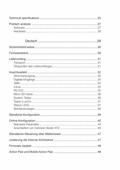
Technical specifications ......................................................................... 25
Problem analysis ................................................................................... 27Software ............................................................................................ 27Hardware ........................................................................................... 28
Deutsch ..................................................................29
Sicherheitshinweise ................................................................................ 30
Firmwarestand ........................................................................................ 30
Lieferumfang .......................................................................................... 31Transport ........................................................................................... 31Überprüfen des Lieferumfanges ......................................................... 31
Anschlussfeld ......................................................................................... 32Stromversorgung ............................................................................... 32Digitale Eingänge ............................................................................... 34DMX .................................................................................................. 34e:bus ................................................................................................. 35RS-232 .............................................................................................. 35Micro SD-Karte .................................................................................. 36System-Taster.................................................................................... 36Taster a und b .................................................................................... 37Status-LEDs ...................................................................................... 37Betriebsanzeigen ............................................................................... 38
Standlone-Konfiguration ........................................................................ 39
Online-Konfiguration .............................................................................. 42Netzwerk-Parameter .......................................................................... 44Anschließen von mehreren Butler XT2 ................................................ 46
Standalone-Steuerung über Webbrowser .............................................. 47
Justierung der internen Echtzeituhr ....................................................... 47
Firmware-Update ................................................................................... 48
Action Pad und Mobile Action Pad ........................................................ 48

5
Setup Manual - Butler XT2
Technische Daten ................................................................................... 49Allgemeine Daten ............................................................................... 49DMX .................................................................................................. 50e:bus ................................................................................................. 50RS-232 .............................................................................................. 50
Problemanalyse ...................................................................................... 51Software ............................................................................................ 51Hardware ........................................................................................... 52
Appendix ................................................................53
Change log ............................................................................................. 54
Dimensions/Abmessungen..................................................................... 56
Connection diagram/Verbindungsbeispiel ............................................. 57
Notes ...................................................................................................... 58

6
Setup Manual - Butler XT2
English

7
Setup Manual - Butler XT2
Security instructions
!The product must only be installed and put into operation by a qualified electrician. The applicable safety regulations and accident prevention regulations must be observed. Otherwise the unit may be damaged.
�Only work on the product when it is de-energized to prevent electrical shocks. Incorrect handling may damage the unit.
!Do not route network, DMX or any other communication line together with power lines. Data traffic or functions can be disturbed.
!The product may only be operated in the operating modes described in the manual. All other applications are considered to be inappropriate use. If the product is not used as intended, there is no guarantee that it will operate safely.
!To prevent the device from overheating, only operate it in well-ventilated environment. The ventilation slots may not be obstructed. Otherwise the unit may overheat and fail.
Device components can reach high temperatures! Let unit cool down after operation before mounting or removing unit to avoid burnings.
!Repairs may only be carried out by authorized, specially trained person-nel to ensure reliability. When in doubt, contact e:cue service. Incorrect handling may damage the unit
!The device must be supplied by a separate certified SELV Class 2 power supply.
Firmware levelThis description relates to firmware version 2.0.3308. Please upgrade your Butler XT2 to this version to use the new functions and features, e. g. web interface for configuration.
8
Setup Manual - Butler XT2
Delivery content Order numbers
y Butler XT2 AA557270131
y microSDHC card for show storage AA6137401HA
y Setup Manual English/German
Optional accessories:
y DIN rail engine accessory pack AA556690035 (power supply, serial cable, LAN cable)
y LAN cross cable 2 m AA666220055
y Serial cable
y e:cue Lighting Application CD AA620030031
y RJ45 to XLR5p adapter cable AA611810135
Transport
Only transport the Butler XT2 in its original packaging. This protects the device from damage. Only unpack the at its installation location. To protect the device against condensation water, unpack it and wait until all moisture remaining in the Butler XT2 has evaporated. Condensation can occur when the device is moved from a cold to a warm location.
Inspect the delivery content
Unpack the Butler XT2 and inspect all parts for completeness. Keep the packag-ing for use in case of further transport. If there is apparent damage to the device or parts are missing from the delivery scope, please contact e:cue service.

9
Setup Manual - Butler XT2
Connector panel
Power
The Butler XT2 must be powered by an external AC/DC Power Supply.
Power over Ethernet and Power over DMX are not supported. Always use an external power supply.
The power supply must meet the following requirements:
y Output Voltage: 24 V DC
y Output Current: >= 1.4 A
Always connect protective ground with the appropriate terminal in the power supply section.
e:net
Use standard shielded CAT5 (RJ45) network cabling for e:net.
Please remember that e:net requires an isolated network segment and cannot operate properly when using e.g. internet or video/au-dio streaming in the same network simultaneously.
10
Setup Manual - Butler XT2
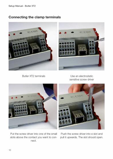
Connecting the clamp terminals
Butler XT2 terminals
Use an electrostatic
sensitive screw driver
Put the screw driver into one of the small slots above the contact you want to con-
nect.
Push the screw driver into e slot and pull it upwards. The slot should open.
11
Setup Manual - Butler XT2
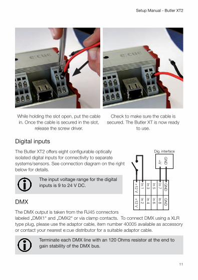
While holding the slot open, put the cable in. Once the cable is secured in the slot,
release the screw driver.
Check to make sure the cable is
secured. The Butler XT is now ready to use.
Digital inputs
+12 V
+12 V
In 1In 2
In 3In 4
In 5In 6
In 7In 8
GN
DG
ND
Dig. interface
+V
GN
D
The Butler XT2 offers eight configurable optically isolated digital inputs for connectivity to separate systems/sensors. See connection diagram on the right below for details.
The input voltage range for the digital inputs is 9 to 24 V DC.
DMX
The DMX output is taken from the RJ45 connectors labeled „DMX1“ and „DMX2“ or via clamp contacts. To connect DMX using a XLR type plug, please use the adaptor cable, item number 40005 available as accessory or contact your nearest e:cue distributor for a suitable adaptor cable.
Terminate each DMX line with an 120 Ohms resistor at the end to gain stability of the DMX bus.
12
Setup Manual - Butler XT2
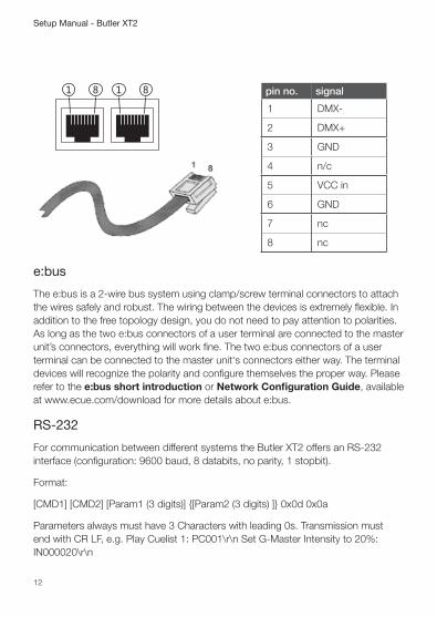
pin no. signal
1 DMX-
2 DMX+
3 GND
4 n/c
5 VCC in
6 GND
7 nc
8 nc
e:bus
The e:bus is a 2-wire bus system using clamp/screw terminal connectors to attach the wires safely and robust. The wiring between the devices is extremely flexible. In addition to the free topology design, you do not need to pay attention to polarities. As long as the two e:bus connectors of a user terminal are connected to the master unit’s connectors, everything will work fine. The two e:bus connectors of a user terminal can be connected to the master unit‘s connectors either way. The terminal devices will recognize the polarity and configure themselves the proper way. Please refer to the e:bus short introduction or Network Configuration Guide, available at www.ecue.com/download for more details about e:bus.
RS-232
For communication between different systems the Butler XT2 offers an RS-232 interface (configuration: 9600 baud, 8 databits, no parity, 1 stopbit).
Format:
[CMD1] [CMD2] [Param1 (3 digits)] {[Param2 (3 digits) ]} 0x0d 0x0a
Parameters always must have 3 Characters with leading 0s. Transmission must end with CR LF, e.g. Play Cuelist 1: PC001\r\n Set G-Master Intensity to 20%: IN000020\r\n
13
Setup Manual - Butler XT2
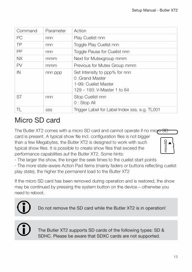
Command Parameter Action
PC nnn Play Cuelist nnn
TP nnn Toggle Play Cuelist nnn
PP nnn Toggle Pause for Cuelist nnn
NX mmm Next for Mutexgroup mmm
PV mmm Previous for Mutex Group mmm
IN nnn ppp Set Intensity to ppp% for nnn 0 :Grand Master 1-99: Cuelist Master 129 – 193: V-Master 1 to 64
ST nnn Stop Cuelist nnn 0 : Stop All
TL sss Trigger Label for Label Index sss, e.g. TL001
Micro SD cardThe Butler XT2 comes with a micro SD card and cannot operate if no micro SD card is present. A typical show file incl. configuration files is not bigger than a few Megabytes, the Butler XT2 is designed to work with such typical show files. It is possible to create show files that exceed the performance capabilities auf the Butler XT2. Some hints: - The larger the show, the longer the seek times to the cuelist start points - The more state-aware Action Pad items (mainly faders or buttons reflecting cuelist play state), the higher the permanent load to the Butler XT2
If the micro SD card has been removed during operation and is restored, the show may be continued by pressing the system button on the device – otherwise you need to reboot.
Do not remove the SD card while the Butler XT2 is in operation!
The Butler XT2 supports SD cards of the following types: SD & SDHC. Please be aware that SDXC cards are not supported.
14
Setup Manual - Butler XT2
Interface elements
Buttons
The System button can be used alone or in combination with the a button. Press the System button and keep it pressed. When a function is displayed release the button and the function will be executed.
In an error condition: Acknowledge notification and reste the system. In normal operation: Long press (ca. 4 seconds): When a blinking rES is displayed, release the button and the Butler XT2 will restart. Button System and “a” in combination: When a blinking dEF is displayed, release the buttons. The Butler XT2 will be reset to factory state. This includes the IP address.
Buttons a and b
For the buttons a and b you can assign functions with the Lighting Application Suite, depending on the operation mode.
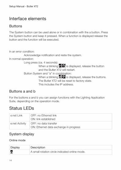
Status LEDs
e:net Link OFF: no Ethernet link ON: link established
e:net Activity OFF: no data transfer ON: Ethernet data exchange in progress
System display
Online mode
Display Description
o A small rotation circle indicated online mode.
15
Setup Manual - Butler XT2
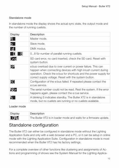
Standalone mode
In standalone mode the display shows the actual sync state, the output mode and the number of running cuelists.
Display Description
A Master mode.
b Slave mode.
d DMX modus.
0... 8 0...8 für number of parallel running cuelists.
Crd SD card error, no card inserted, check the SD card. Reset with system button.
EP e:bus overload due to over current or power failure. This can happen when connecting devices with high inrush current during operation. Check the e:bus for shortcuts and the power supply for correct supply voltage. Reset with the system button.
EC Configuration of the e:bus failed. If repeated please contact the e:cue service.
SEr The serial number could not be read. Rest the system. If the error happens again, please contact the e:cue service.
S A blinking S indicates standby. The Butler XT2 is in standalone mode, but no cuelists are running or no cuelists available.
Loader mode
Display Description
LOAd The Butler XT2 is in loader mode and waits for a firmware update.
Standalone configurationThe Butler XT2 can either be configured in standalone mode without the Lighting Application Suite and only with a web browser and a PC, or it can be setup in online mode with the Lighting Application Suite. Configuration in standalone mode is most recommended when the Butler XT2 has his factory settings. For a complete overview of other functions like clustering and assignments of Ac-tions and programming of shows see the System Manual for the Lighting Applica-

16
Setup Manual - Butler XT2
tion Suite, available for download from www.ecue.com for free.
When the Butler XT2 is in online mode all defined Triggers and Actions are run in the Programmer. For standalone mode only those Triggers and Actions get exported that the Butler XT2 can handle in standalone mode. All online mode-only Actions and Triggers are not exported.
Using the standalone web interface
You can set the network parameters of the Butler XT2 without any other system using a standard web browser on any PC or PC-like system. Connect the Butler XT2 with power and via a standard LAN patch cable over an Ethernet switch to the server (LCE or PC). If you want to connect the Butler XT2 without Ethernet switch to the server use a so called cross cable, as not all Ethernet interfaces support automatic RX/TX detection.
LAN
Ethernet switch
Power supply
Butler XT2
RJ45RJ45
24 V DC
Start the web browser and enter the IP address of the Butler XT2 in the address field of the browser, in factory state 192.168.123.1 (if the Butler was configured differently before and you do not know the IP address, perform a »Reset to factory settings«). You can now see the current settings and parameters.

17
Setup Manual - Butler XT2
To change the configuration, click the upper Configure button and enter the pass-word. The default password is “ecue”, it can be changed during configuration.
Click Enter and the main configuration dialogue gets displayed. Change the parameters (explained in the following chapter) and click Submit.
Set the parameters and click Submit to save the changes. See the next chapter for a description of the parameters.
18
Setup Manual - Butler XT2
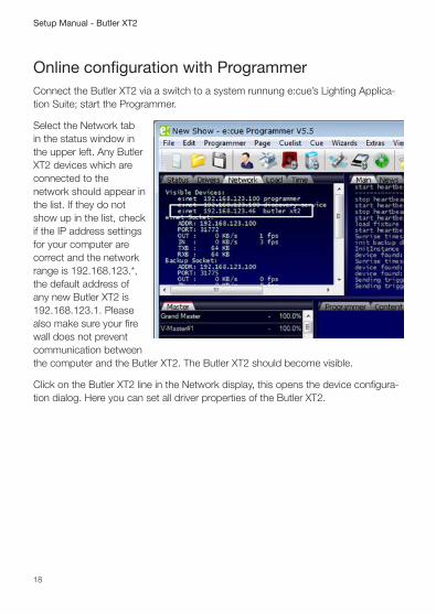
Online configuration with ProgrammerConnect the Butler XT2 via a switch to a system runnung e:cue’s Lighting Applica-tion Suite; start the Programmer.
Select the Network tab in the status window in the upper left. Any Butler XT2 devices which are connected to the network should appear in the list. If they do not show up in the list, check if the IP address settings for your computer are correct and the network range is 192.168.123.*, the default address of any new Butler XT2 is 192.168.123.1. Please also make sure your fire wall does not prevent communication between the computer and the Butler XT2. The Butler XT2 should become visible.
Click on the Butler XT2 line in the Network display, this opens the device configura-tion dialog. Here you can set all driver properties of the Butler XT2.

19
Setup Manual - Butler XT2
Click the IP address – typically this should read 192.168.123.1 at this stage, when the Butler XT2 is still set to factory defaults.
y Assign a new IP address e.g. 192.168.123.200.
y Use the same procedure for the remaining network parameters: Subnet Mask - usually 255.255.255.0, Gateway – no gateway
y Give the Butler XT2 a unique name.
y Set the base time, this is the time without DST cor-rection, add shift and dates for DST begin and end.
y Do not modify DMX settings except you know what you are doing.
y See the following table for a complete overview of network parameters.
y Apply the changes with the Ok button
If no show is exported to the Butler XT2, e. g. when the Butler XT2 is in factory state, no DST information and master/slave settings are available. As soon as a show has been downloaded, correct DST information and master/slave setting will be shown.
20
Setup Manual - Butler XT2
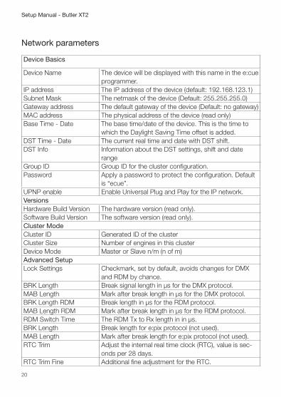
Network parameters
Device Basics
Device Name The device will be displayed with this name in the e:cue programmer.
IP address The IP address of the device (default: 192.168.123.1)Subnet Mask The netmask of the device (Default: 255.255.255.0)Gateway address The default gateway of the device (Default: no gateway)MAC address The physical address of the device (read only)Base Time - Date The base time/date of the device. This is the time to
which the Daylight Saving Time offset is added.DST Time - Date The current real time and date with DST shift.DST Info Information about the DST settings, shift and date
rangeGroup ID Group ID for the cluster configuration.Password Apply a password to protect the configuration. Default
is “ecue”.UPNP enable Enable Universal Plug and Play for the IP network.VersionsHardware Build Version The hardware version (read only).Software Build Version The software version (read only).Cluster ModeCluster ID Generated ID of the clusterCluster Size Number of engines in this clusterDevice Mode Master or Slave n/m (n of m)Advanced SetupLock Settings Checkmark, set by default, avoids changes for DMX
and RDM by chance.BRK Length Break signal length in µs for the DMX protocol.MAB Length Mark after break length in µs for the DMX protocol.BRK Length RDM Break length in µs for the RDM protocol.MAB Length RDM Mark after break length in µs for the RDM protocol.RDM Switch Time The RDM Tx to Rx length in in µs.BRK Length Break length for e:pix protocol (not used).MAB Length Mark after break length for e:pix protocol (not used).RTC Trim Adjust the internal real time clock (RTC), value is sec-
onds per 28 days.RTC Trim Fine Additional fine adjustment for the RTC.

21
Setup Manual - Butler XT2
To add the Butler XT2 to the Programmer configuration start the Device Manager.
Execute the Automatic Setup Wizard. The Butler XT2 will be found and displayed:
Set the checkmark for the Butler XT2 to add it to your setup or click the Select button. Clear the checkmark for the e:bus scan if there are no e:bus components.To set the driver properties for the Butler XT2 double-click the Butler XT2 in den device overview of the Device Manager.
Click Ok to add the Butler XT2 to the Pro-grammer configuration, the Butler XT2 is now available.
Double-click the new Butler XT2 in the Device
22
Setup Manual - Butler XT2
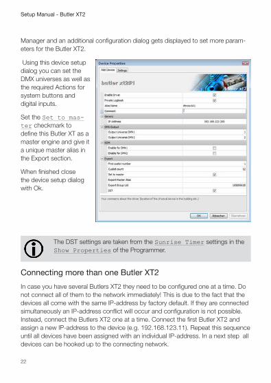
Manager and an additional configuration dialog gets displayed to set more param-eters for the Butler XT2.
Using this device setup dialog you can set the DMX universes as well as the required Actions for system buttons and digital inputs.
Set the Set to mas-ter checkmark to define this Butler XT as a master engine and give it a unique master alias in the Export section.
When finished close the device setup dialog with Ok.
The DST settings are taken from the Sunrise Timer settings in the Show Properties of the Programmer.
Connecting more than one Butler XT2
In case you have several Butlers XT2 they need to be configured one at a time. Do not connect all of them to the network immediately! This is due to the fact that the devices all come with the same IP-address by factory default. If they are connected simultaneously an IP-address conflict will occur and configuration is not possible. Instead, connect the Butlers XT2 one at a time. Connect the first Butler XT2 and assign a new IP-address to the device (e.g. 192.168.123.11). Repeat this sequence until all devices have been assigned with an individual IP-address. In a next step all devices can be hooked up to the connecting network.
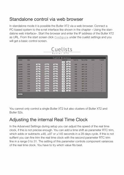
Standalone control via web browserIn standalone mode it is possible the Butler XT2 via a web browser. Connect a PC-based system to the e:net interface like shown in the chapter » Using the stan-dalone web interface«. Start the browser and enter the IP address of the Butler XT2 as URL. From the start screen click Configure under the cuelist settings and you will get a basic control screen.
You cannot only control a single Butler XT2 but also clusters of Butler XT2 and Butler S2s.
Adjusting the internal Real Time ClockIn the Advanved Settings during setup you can adjust the speed of the real time clock, if this is not precise enough. You can add a time shift as parameter RTC trim, which adds or subtracts ±48, ±97 or ±145 seconds in a 28 days cycle. If this is not suffient you can fine trim the real time clock with the second parameter RTC trim fine in a range 0 to 31. The setting of this parameter controls component variances of the real time clock. You have to try which value fits best.
24
Setup Manual - Butler XT2
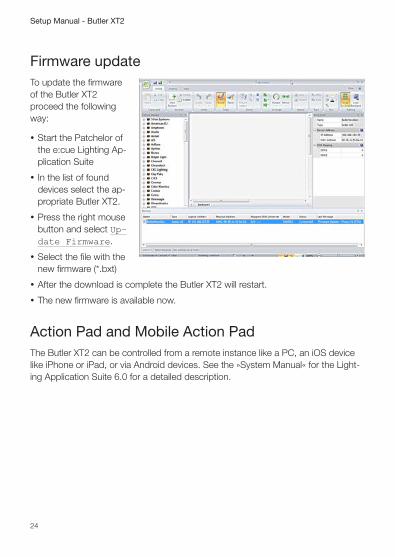
Firmware updateTo update the firmware of the Butler XT2 proceed the following way:
y Start the Patchelor of the e:cue Lighting Ap-plication Suite
y In the list of found devices select the ap-propriate Butler XT2.
y Press the right mouse button and select Up-date Firmware.
y Select the file with the new firmware (*.bxt)
y After the download is complete the Butler XT2 will restart.
y The new firmware is available now.
Action Pad and Mobile Action PadThe Butler XT2 can be controlled from a remote instance like a PC, an iOS device like iPhone or iPad, or via Android devices. See the »System Manual« for the Light-ing Application Suite 6.0 for a detailed description.

25
Setup Manual - Butler XT2
Technical specificationsGeneral specifications
Dimensions 177 x 60 x 75 mm/7 x 2.4 x 3 inch
Weight 0.4 kg/0.88 lbs
Power 12 … 24 V DC via terminals
Operating/storage temp. 0 … 40 °C/32 … 104 °F
Operating/storage hum. 0 … 80%, non-condensing
Protection class IP20, SELV
Housing Aluminium, polyamide 6.6
Mounting on 35 mm DIN rail
Max. start up time after 10 seconds voltage interruption
Engine specifications
User interface 3 Buttons, 5 LEDs, 7-segment-LED
System links 1 x e:bus (clamp terminals) 1 x e:net (RJ45 Ethernet) 1 x RS-232 (clamp terminals) 2 x DMX (RJ45, clamp terminals) 8 x optically isolated digital inputs
Display 7-segment LED
Data storage on micro SD card
e:net specification
Connection RJ45, 8P8C
Speed 100 MBit/s
POE capability no
DMX output specification
Number of outputs 2 DMX universes, 1024 channels

26
Setup Manual - Butler XT2
Short circuit protection yes, reversible
Over-voltage protection yes
DMX operation Acc. DMX-512A standard
Optical isolation yes, 3 kV max.
e:bus specification
Number of outputs 1 x clamp terminals
Short circuit protection yes, reversible
Over-voltage protection yes
Max. output current 1.2 A
Max. # Glass Touches 8
Optical isolation no
Digital inputs specification
Number of inputs 8 clamp terminals
Optical isolation yes, 3 kV max.
Max. voltage 24 V
Max. current per channel 10 mA
Short circuit protection yes, reversible
Over-voltage protection yes
RS-232
Transfer rate & Configuration 9600 baud, 8 bits, no parity, 1 stopbit
Optical isolation yes, 3 kV
The Butler XT2 is certified according to: EN 55022, EN 55024, EN 60950
Conforms to ANSi/UL Std. 60950-1. Certified to CAN/CSA Std. C22.2#60950-1.
4006376
27
Setup Manual - Butler XT2
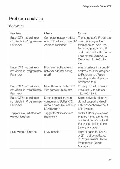
Problem analysis
Software
Problem Check Cause
Butler XT2 not online or not visible in Programmer/Patchelor
Computer network adapt-er with fixed and correct IP Address assigned?
The computer’s IP address must be assigned as fixed address. Also, the first three parts of the IP address must be the same IP as for the Butler XT2. Example: 192.168.123.xxx.
Butler XT2 not online or not visible in Programmer/Patchelor
Programmer/Patchelor network adapter config-ured?
e:net interface included IP address must be assigned to Programmer/Patch-elor (Application Options, Advanced tab).
Butler XT2 not online or not visible in Programmer/Patchelor
More than one Butler XT2 with same IP address?
Factory default of Traxon Products is IP address 192.168.123.1.
Butler XT2 not online or not visible in Programmer/Patchelor
Direct connection from computer to Butler XT2, without cross link cable or LAN switch?
Some network adapters do not support a direct LAN connection (without LAN switch).
Triggers like “Initialisation” without function.
Trigger for “Initialisation” assigned?
Butler XT2 only executes triggers if they are config-ured and transferred with the Quick Update in the Device Manager.
RDM without function RDM enable RDM “Enable for DMX 1 or 2” must be activated in Programmer’s Device Properties in Device Manager.
28
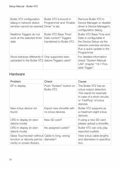
Setup Manual - Butler XT2
Butler XT2 configuration dialog in network status window cannot be opened
Butler XT2 is bound in Programmer and “Enable Driver” is set.
Remove Butler XT2 in Device Manager or disable driver is Device Manager’s configuration dialog.
Realtime Triggers do not work at the selected time/date
Butler XT2 Base Time/Date correct? Triggers transferred to Butler XT2
Butler XT2 Base Time and Date is configurable in the Device Setup via the network overview window. Run a quick update in the Programmer.
Show behaves differently if uploaded to the Butler XT2
Only supported stan-dalone Triggers used?
For detailed information check “System Manual LAS” chapter “16.7 Pos-sible Trigger”.
Hardware
Problem Check Cause
EP in display Push “System” button on Butler XT2.
The Butler XT2 has an e:bus output detection. This reacts for example in case of a short circuits, or “HotPlug” of e:bus devices.
New e:bus device not found
Export new showfile with no e:bus devices.
Butler XT2 supports as a maximum eight e:bus devices.
CRD in display (in stan-dalone mode)
New SD card? If using a new SD card please upload a showfile..
CRD in display (in stan-dalone mode)
No assigned cuelist? Butler XT2 can only play exported cuelists.
Glass Touchscreen without function or reboots perma-nently or screen flickers.
Cable to long, wrong diameter?
View e:bus cable lengths and diameters in specifica-tion.

29
Setup Manual - Butler XT2
Deutsch

30
Setup Manual - Butler XT2
Sicherheitshinweise
!Das Produkt darf nur von einer Elektrofachkraft installiert und in Betrieb genommen werden. Die geltenden Sicherheits- und Unfallverhütungs-vorschriften sind zu beachten.
�Arbeiten an dem Produkt nur im spannungsfreien Zustand durchführen. Anderenfalls kann zu elektrischen Schocks kommen oder das Gerät wird beschädigt.
!Netzwerk, DMX oder andere Kommunikationsleitungen nicht zusammen mit Netzleitung verlegen. Die Datenkommunikation kann gestört werden oder Funktionen des Gerätes werden eingeschränkt.
!Das Produkt darf nur mit den in der Anleitung aufgeführten Betriebsarten betrieben werden. Alle anderen Anwendungen gelten als sachwidrig. Wird das Produkt nicht bestimmungsgemäß verwendet, ist kein sicherer Betrieb gewährleistet. Schäden oder Störungen können die Folge sein.
!Um ein Überhitzen des Gerätes zu verhindern, darf es nur in gut belüfteten Umgebungen betrieben werden. Lüftungsschlitze dürfen nicht abgedeckt werden. Durch Überhitzung wird das Gerät beschädigt.
Das Gerät oder Teile des Gerätes können im Betrieb heiß werden. Zur Montage oder Demontage das Gerät ausreichend abkühlen lassen um Verbrennungen zu vermeiden.
!Reparaturen am Gerät dürfen nur von geschultem oder ausgebildeten Personal vorgenommen werden. Im Zweifelsfall kontaktieren Sie e:cue. Fehlerhafte Reparaturen können das Gerät beschädigen.
!Das Gerät muss durch ein separates zertifiziertes SELV Class 2-Netzteil versorgt werden.
FirmwarestandDiese Beschreibung bezieht sich auf den Firmwarestand 2.0.3308. Um die hier beschriebenen Features und Funktionen nutzen zu können, bringen Sie den Butler XT2 bitte auf den aktuellen Firmwarestand.
31
Setup Manual - Butler XT2
Lieferumfang y Butler XT2 AA557270131
y microSDHC-Karte für Show-Speicherung AA6137401HA
y Setup Manual English/German
Optionales Zubehör
y DIN Rail Engine Accessory Pack AA556690035 (Netzteil, serielles Kabel, LAN-Kabel)
y LAN Cross-Kael 2 m AA666220055
y Serielles Kabel
y e:cue Lighting Application CD AA620030031
y RJ45 auf XLR5p Adapterkabel AA611810135
Transport
Transportieren Sie den Butler XT2 nur in seiner originalen Verpackung um Schäden zu vermeiden. Entpacken Sie den Butler XT2 nur am Installationsort. Um Schäden bei Wechsel von Kälte zu Wärme durch Kondensationswasser zu verhindern, warten Sie nach dem Auspacken, bis das Gerät die Temperatur am Installationsort angenommen hat.
Überprüfen des Lieferumfanges
Entpacken Sie den Butler XT2 und überprüfen Sie die Vollständigkeit des Liefer-umfanges. Bewahren Sie die Verpackung für einen späteren Transport auf. Sollten Komponenten beschädigt sein oder fehlen, wenden Sie sich an Ihren e:cue-Service.
32
Setup Manual - Butler XT2
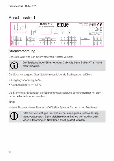
Anschlussfeld
Stromversorgung
Der ButlerXT2 wird von einem externen Netzteil versorgt.
Die Speisung über Ethernet oder DMX wie beim Butler XT ist nicht mehr möglich.
Die Stromversorgung über Netzteil muss folgende Bedingungen erfüllen:
y Ausgangsspannung 24 V=
y Ausgangsstrom: >= 1.3 A
Die Klemme für Erdung an der Spannnungsversorgung sollte unbedingt mit dem Schutzleiter verbunden werden.
e:net
Nutzen Sie geschirmte Standard-CAT5 (RJ45)-Kabel für den e:net-Anschluss.
Bitte berücksichtigen Sie, dass e:net ein eigenes Netzwerk-Seg-ment voraussetzt. Beim gleichzeitigem Betrieb von Audio- oder Video-Streaming im Netz kann e:net gestört werden.
33
Setup Manual - Butler XT2
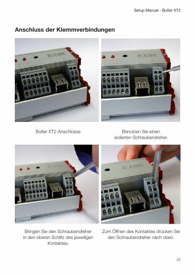
Anschluss der Klemmverbindungen
Butler XT2-Anschlüsse
Benutzen Sie einen
isolierten Schraubendreher.
Bringen Sie den Schraubendreher
in den oberen Schlitz des jeweiligen Kontaktes.
Zum Öffnen des Kontaktes drücken Sie
den Schraubendreher nach oben.

34
Setup Manual - Butler XT2
Während Sie den Kontakt offen halten, führen Sie den Anschlussdraht in den
Kontakt ein.
Versichern Sie sich, dass der Anschluss
auch wirklich fest sitzt.
Digitale Eingänge
+12 V
+12 V
In 1In 2
In 3In 4
In 5In 6
In 7In 8
GN
DG
ND
Dig. interface
+V
GN
D
Der Butler XT2 verfügt über acht konfigurierbare, optoelektrisch isolierte Eingänge zum Anschluss von Fremdsystemen oder Sensoren.
Der Eingangsspannungs-Bereich für die digitalen Eingänge beträgt 9 bis 24 V=-
DMX
Die DMX-Ausgänge liegen auf den RJ45-Anschlüssen DMX1 and DMX2 als auch auf Klemmanschlüssen. Für Verbindungen über XLR-Anschlüsse nutzen Sie bitte RJ45-zu-XLR-Adapter, die Sie auch bei ihrem e:cue-Händler erhalten können.
Terminieren Sie jede DMX-Leitung am Ende mit einem 120 Ohm-Widerstand. Dies erhöht die Stabilität des DMX-Busses.
35
Setup Manual - Butler XT2
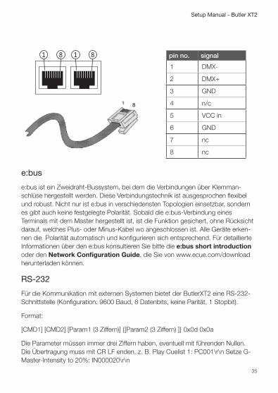
pin no. signal
1 DMX-
2 DMX+
3 GND
4 n/c
5 VCC in
6 GND
7 nc
8 nc
e:bus
e:bus ist ein Zweidraht-Bussystem, bei dem die Verbindungen über Klemman-schlüse hergestellt werden. Diese Verbindungstechnik ist ausgesprochen flexibel und robust. Nicht nur ist e:bus in verschiedensten Topologien einsetzbar, sondern es gibt auch keine festgelegte Polarität. Sobald die e:bus-Verbindung eines Terminals mit dem Master hergestellt ist, ist die Funktion gesichert, ohne Rücksicht darauf, welches Plus- oder Minus-Kabel wo angeschlossen ist. Alle Geräte erken-nen die Polarität automatisch und konfigurieren sich entsprechend. Für detaillierte Informationen über den e:bus konsultieren Sie bitte die e:bus short introduction oder den Network Configuration Guide, die Sie von www.ecue.com/download herunterladen können.
RS-232
Für die Kommunikation mit externen Systemen bietet der ButlerXT2 eine RS-232- Schnittstelle (Konfiguration: 9600 Baud, 8 Datenbits, keine Parität, 1 Stopbit).
Format:
[CMD1] [CMD2] [Param1 (3 Ziffern)] {[Param2 (3 Ziffern) ]} 0x0d 0x0a
Die Parameter müssen immer drei Ziffern haben, eventuell mit führenden Nullen. Die Übertragung muss mit CR LF enden, z. B. Play Cuelist 1: PC001\r\n Setze G-Master-Intensity to 20%: IN000020\r\n

36
Setup Manual - Butler XT2
Befehl Parameter Funktion
PC nnn Spiele Cuelist nnn
TP nnn Start/Stop-Wechsel Cuelist nnn
PP nnn Pause für Cuelist nnn
NX mmm Nächste für Mutexgroup mmm
PV mmm Vorherige für Mutex Group mmm
IN nnn ppp Setze Helligkeit auf ppp% für nnn 0 :Grand Master 1-99: Cuelist Master 129 – 193: V-Master 1 bis 64
ST nnn Stop Cuelist nnn 0 : Stop Alle
TL sss Trigger Label für Label Index sss, z.B. TL001
Micro SD-Karte
Der ButlerXT2 wird mit einer MicroSD-Karte geliefert und kann ohne diese SD-Karte nicht betrieben werden. Ein typisches Showfile inkl. Konfigurationsdateien ist normalerweise nicht größer als einige Megabytes und auf solche Shows ist der Betrieb des Butler XT2 ausgelegt. Dennoch ist es möglich Shows zu erstellen welche die Kapazität überschreiten. Im Folgenden ein paar Hinweise: - Je größer die Show, desto größer werden die Zugriffszeiten zu den Cuelist Startpunkten. - Je größer die Anzahl der dynamischen Action Pad Elemente (hauptsächlich Fader oder Buttons welche Cuelisten Zustände wiedergeben), desto größer ist die permanente Grundlast des Butler XT2. Wurde die Karte während des Betriebes entnommen und wieder eingesetzt, kann die Show durch Drücken des System-Tasters wieder gestartet werden. Sollte dieses nicht ausreichen, muss der Butler durch einen Reset neu gestartet werden.
Entfernen Sie die SD-Karte nicht während des Betriebes!
Der Butler XT2 unterstützt SD Karten der folgenden Formate: SD & SDHC. Bitte beachten: SDXC Karten werden nicht unterstützt !
37
Setup Manual - Butler XT2
Bedienelemente
System-Taster
Der System-Taster kann alleine oder in Kombination mit der a-Taste genutzt werden. Der Taster wird gehalten und sobald eine Funktionsanzeige auf dem Display angezeigt wird, kann der Taster losgelassen werden und die Funktion wird ausgeführt.
Im Fehlerzustand: Bestätigt die Meldung und startet das Systeme neu. Im Normalbetrieb: Lang drücken: (ca. 4 Sekunden): Sobald ein blinkendes rES angezeigt wird, Taster los lassen und der Butler XT2 wird neu gestartet. Taster System und Taster “a” zusammen: Ein blinkendes dEF wird angezeigt. Taster los lassen und der Butler XT2 wird auf Werkseinstellungen zurück gesetzt. Dieses schließt die IP-Adresse ein.
Taster a und b
Die Taster a und b können je nach Betriebsmodus frei mit Funktionen belegt werden.
Status-LEDs
PWR On Der Butler XT2 wird mit Spannung versorgt.
e:bus Power AUS: Die Versorgungsspannung liegt unter 24 V. AN: e:bus-Betrieb ist korrekt- Wechselnd: e:bus-Überstrom oder Unterversorgung.
Error AUS: System arbeitet normal. AN: Fehlerzustand, siehe Anzeige.
e:net Link AUS: Keine Ethernet-Verbindung AN: Verbindung hergestellt.
e:net Activity AUS: Kein Datentransfer AN: Datentransfer findet statt.

38
Setup Manual - Butler XT2
Betriebsanzeigen
Online-Modus
Anzeige Bedeutung
o Ein kleiner rotierender Kreis zeigt den Online-Modus an.
Standalone-Modus
Im Standalone-Modus zeigt das Display nacheinander den aktuellen Synchronisa-tionstand, den Ausgabe-Modus und die Anzahl ablaufender Cuelists an.
Display Message
A Master-Modus.
b Slave-Modus.
d DMX-Modus.
0... 8 0...8 für Anzahl parallel laufender Cuelists.
Crd SD-Kartenfehler, keine Karte eingesetzt, prüfen Sie die SD-Karte, Rücksetzen mit dem System-Taster.
EP e:bus-Spannungsfehler wegen Überstrom oder Unterspannung. Kann Auftreten beim Anschluss von Geräten mit hohem Einschalt-strom. Prüfen Sie den e:bus auf Kurzschlüsse und das Netzteil auf korrekte Spannung. System-Taster setzt den Fehler zurück.
EC Die Konfiguration des e:bus schlug fehl. Falls der Fehler wieder auftritt, verständigen Sie den Service.
SEr Die Seriennummer konnte nicht gelesen werden. Starten Sie das System neu, falls der Fehler wieder auftritt, verständigen Sie den Service.
S Ein blinkendes S zeigt Standby an, Butler XT2 in Standalone-Modus, aber es läuft keine Cuelist oder es sind keine Cuelists verfügbar.
Loader-Modus
Display Description
LOAd Der Butler XT2 ist im Loader-Modus und wartet auf eine neue Firmware.
39
Setup Manual - Butler XT2
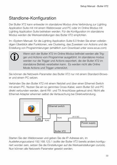
Standlone-KonfigurationDer Butler XT2 kann entweder im standalone Modus ohne Verbindung zur Lighting Application Suite mit mit einem Webbrowser und PC oder im Online Modus mit Lighting Application Suite betrieben werden. Für die Konfiguration im standalone Modus werden die Werkseinstellungen des Butler XT2 empfohlen.
Im »System Manual« für die Lighting Application Suite 6.0 finden Sie einen vollstän-digen Überblick aller Funktionen, wie Clustering, das Zuweisen von Actions und die Erstellung von Programmierungen (erhältlich zum Download unter www.ecue.com)
Wenn sich der Butler XT2 im Online Modus befindet werden alle Trig-ger und Actions vom Programmer ausgeführt. Im standalone modus werden nur die Trigger und Actions exportiert, die der Butler XT2 im standalone Betrieb verarbeiten kann. Es werden nicht alle Online Mode Actions und Trigger unterstützt.
Sie können die Netzwerk-Parameter des Butler XT2 nur mit einem Standard-Brows-er und einem PC setzen.
Verbinden Sie den Butler XT2 mit einem Netzteil und über einen Ethernet-Switch mit einem PC. Nutzen Sie ein so gennntes Cross-Kabel, wenn Butler S2 und PC direkt verbunden werden, damit RX- und TX-Anschlüsse gekreuzt sind. Nicht alle Ethernet-Adapter erkennen selbst die Vertauschung bei Direktverbindung.
LAN
Ethernet switch
Power supply
Butler XT2
RJ45RJ45
24 V DC
Starten Sie den Webbrowser und geben Sie die IP-Adresse ein, im Auslieferungszustand 192.168.123.1 (sollte der Butler XT2 bereits anders konfigu-riert worden sein, setzen Sie die Einstellungen auf die Werkseinstellungen zurück). Nun können alle Netzwerk-Parameter gesetzt werden.

40
Setup Manual - Butler XT2
Zum Ändern der Konfiguration clicken Sie Configure und geben Sie das Passwort ein. Das Passwort ab Werk ist “ecue”, es kann später geändert werden.
Clicken Sie Enter und der Hauptdialog wird angezeigt. Stellen Sie die Netzwerk-Parameter neu ein und clicken Sie Submit.

41
Setup Manual - Butler XT2
Eine Erklärung der Parameter finden Sie im nächsten Kapitel.
42
Setup Manual - Butler XT2
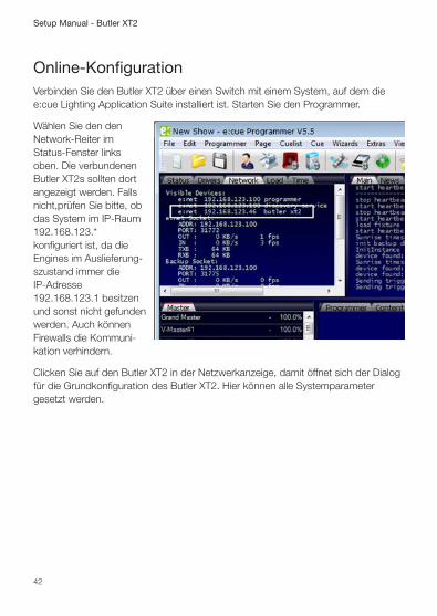
Online-KonfigurationVerbinden Sie den Butler XT2 über einen Switch mit einem System, auf dem die e:cue Lighting Application Suite installiert ist. Starten Sie den Programmer.
Wählen Sie den den Network-Reiter im Status-Fenster links oben. Die verbundenen Butler XT2s sollten dort angezeigt werden. Falls nicht,prüfen Sie bitte, ob das System im IP-Raum 192.168.123.* konfiguriert ist, da die Engines im Auslieferung-szustand immer die IP-Adresse 192.168.123.1 besitzen und sonst nicht gefunden werden. Auch können Firewalls die Kommuni-kation verhindern.
Clicken Sie auf den Butler XT2 in der Netzwerkanzeige, damit öffnet sich der Dialog für die Grundkonfiguration des Butler XT2. Hier können alle Systemparameter gesetzt werden.
43
Setup Manual - Butler XT2
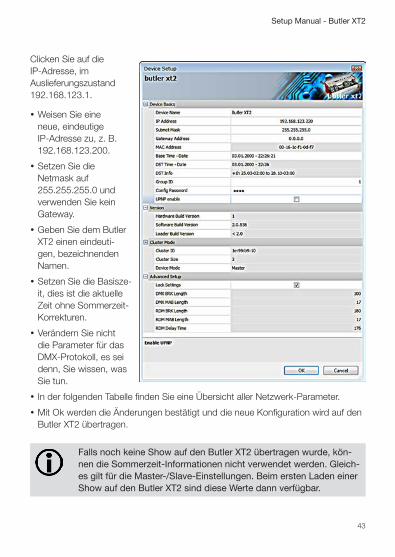
Clicken Sie auf die IP-Adresse, im Auslieferungszustand 192.168.123.1.
y Weisen Sie eine neue, eindeutige IP-Adresse zu, z. B. 192.168.123.200.
y Setzen Sie die Netmask auf 255.255.255.0 und verwenden Sie kein Gateway.
y Geben Sie dem Butler XT2 einen eindeuti-gen, bezeichnenden Namen.
y Setzen Sie die Basisze-it, dies ist die aktuelle Zeit ohne Sommerzeit-Korrekturen.
y Verändern Sie nicht die Parameter für das DMX-Protokoll, es sei denn, Sie wissen, was Sie tun.
y In der folgenden Tabelle finden Sie eine Übersicht aller Netzwerk-Parameter.
y Mit Ok werden die Änderungen bestätigt und die neue Konfiguration wird auf den Butler XT2 übertragen.
Falls noch keine Show auf den Butler XT2 übertragen wurde, kön-nen die Sommerzeit-Informationen nicht verwendet werden. Gleich-es gilt für die Master-/Slave-Einstellungen. Beim ersten Laden einer Show auf den Butler XT2 sind diese Werte dann verfügbar.
44
Setup Manual - Butler XT2
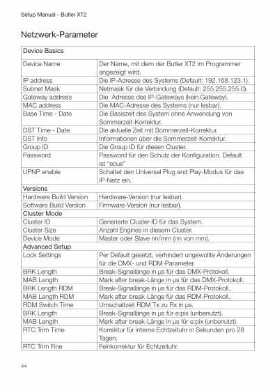
Netzwerk-Parameter
Device Basics
Device Name Der Name, mit dem der Butler XT2 im Programmer angezeigt wird.
IP address Die IP-Adresse des Systems (Default: 192.168.123.1).Subnet Mask Netmask für die Verbindung (Default: 255.255.255.0).Gateway address Die Adresse des IP-Gateways (kein Gateway).MAC address Die MAC-Adresse des Systems (nur lesbar).Base Time - Date Die Basiszeit des System ohne Anwendung von
Sommerzeit-Korrektur.DST Time - Date Die aktuelle Zeit mit Sommerzeit-Korrektur.DST Info Informationen über die Sommerzeit-Korrektur.Group ID Die Group ID für diesen Cluster.Password Password für den Schutz der Konfiguration. Default
ist “ecue”UPNP enable Schaltet den Universal Plug and Play-Modus für das
IP-Netz ein.VersionsHardware Build Version Hardware-Version (nur lesbar).Software Build Version Firmware-Version (nur lesbar).Cluster ModeCluster ID Generierte Cluster-ID für das System.Cluster Size Anzahl Engines in diesem Cluster.Device Mode Master oder Slave nn/mm (nn von mm).Advanced SetupLock Settings Per Default gesetzt, verhindert ungewollte Änderungen
für die DMX- und RDM-Parameter.BRK Length Break-Signallänge in µs für das DMX-Protokoll.MAB Length Mark after break-Länge in µs für das DMX-Protokoll.BRK Length RDM Break-Signallänge in µs für das RDM-Protokoll..MAB Length RDM Mark after break-Länge für das RDM-Protokoll..RDM Switch Time Umschaltzeit RDM Tx zu Rx in µs.BRK Length Break-Signallänge in µs für e:pix (unbenutzt).MAB Length Mark after break-Länge in µs für e:pix (unbenutzt).RTC Trim Time Korrektur für interne Echtzeituhr in Sekunden pro 28
Tagen.RTC Trim Fine Feinkorrektur für Echtzeituhr.
45
Setup Manual - Butler XT2
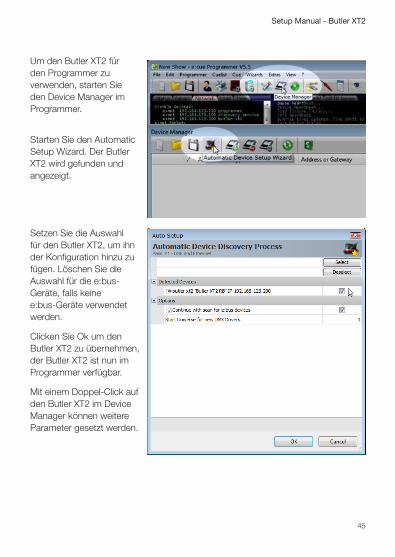
Um den Butler XT2 für den Programmer zu verwenden, starten Sie den Device Manager im Programmer.
Starten Sie den Automatic Setup Wizard. Der Butler XT2 wird gefunden und angezeigt.
Setzen Sie die Auswahl für den Butler XT2, um ihn der Konfiguration hinzu zu fügen. Löschen Sie die Auswahl für die e:bus-Geräte, falls keine e:bus-Geräte verwendet werden.
Clicken Sie Ok um den Butler XT2 zu übernehmen, der Butler XT2 ist nun im Programmer verfügbar.
Mit einem Doppel-Click auf den Butler XT2 im Device Manager können weitere Parameter gesetzt werden.
46
Setup Manual - Butler XT2
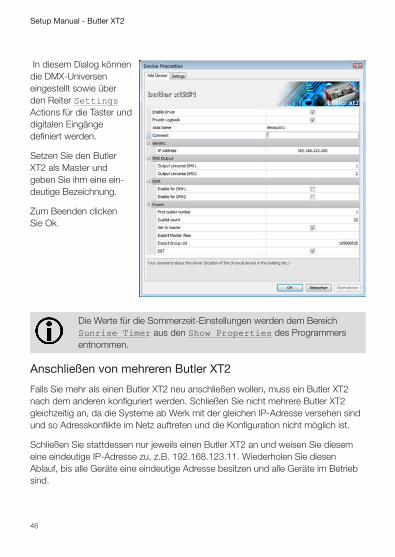
In diesem Dialog können die DMX-Universen eingestellt sowie über den Reiter Settings Actions für die Taster und digitalen Eingänge definiert werden.
Setzen Sie den Butler XT2 als Master und geben Sie ihm eine ein-deutige Bezeichnung.
Zum Beenden clicken Sie Ok.
Die Werte für die Sommerzeit-Einstellungen werden dem Bereich Sunrise Timer aus den Show Properties des Programmers entnommen.
Anschließen von mehreren Butler XT2
Falls Sie mehr als einen Butler XT2 neu anschließen wollen, muss ein Butler XT2 nach dem anderen konfiguriert werden. Schließen Sie nicht mehrere Butler XT2 gleichzeitig an, da die Systeme ab Werk mit der gleichen IP-Adresse versehen sind und so Adresskonflikte im Netz auftreten und die Konfiguration nicht möglich ist.
Schließen Sie stattdessen nur jeweils einen Butler XT2 an und weisen Sie diesem eine eindeutige IP-Adresse zu, z.B. 192.168.123.11. Wiederholen Sie diesen Ablauf, bis alle Geräte eine eindeutige Adresse besitzen und alle Geräte im Betrieb sind.
47
Setup Manual - Butler XT2
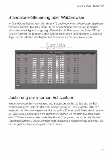
Standalone-Steuerung über WebbrowserIm Standalone-Betrieb kann der Butler XT2 auch über einen Webbrowser gesteuert werden. Schließen Sie dazu einen PC mit einem Webbrowser an wie im Kapitel »Standalone-Konfiguration« gezeigt. Geben Sie die IP-Adresse des Butler XT2 als URL im Browser an. Danach clicken Sie Configure unter dem Abschnitt Cuelist Set-tings und Sie erhalten eine Möglichkeit Cuelist zu starten oder zu stoppen.
Justierung der internen EchtzeituhrIn den Advanced Settings während des Setup können Sie die Taktrate der Ech-tzeituhr korrigieren, falls die Uhr nicht präzise genug ist. Der Parameter RTC trim verändert die Geschwindigkeit der Uhr um ±48, ±97 oder ±145 Sekunden in einem 28 Tage-Zyklus. Sollte dies nicht ausreichen, können Sie mit dem zweiten Param-eter RTC trim fine einen Wert zwischen 0 und 31 angeben, der nochmals Bauteil-Toleranzen korrigiert. Diesen zweiten Wert müssen Sie versuchsweise einstellen, bis Sie die gewünschte Genauigkeit erreicht haben.
48
Setup Manual - Butler XT2
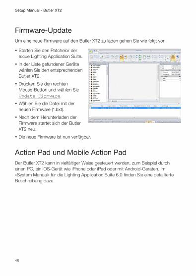
Firmware-UpdateUm eine neue Firmware auf den Butler XT2 zu laden gehen Sie wie folgt vor:
y Starten Sie den Patchelor der e:cue Lighting Application Suite.
y In der Liste gefundener Geräte wählen Sie den entsprechenden Butler XT2.
y Drücken Sie den rechten Mouse-Button und wählen Sie Update Firmware.
y Wählen Sie die Datei mit der neuen Firmware (*.bxt).
y Nach dem Herunterladen der Firmware startet sich der Butler XT2 neu.
y Die neue Firmware ist nun verfügbar.
Action Pad und Mobile Action PadDer Butler XT2 kann in vielfältiger Weise gesteuert werden, zum Beispiel durch einen PC, ein iOS-Gerät wie iPhone oder iPad oder mit Android-Geräten. Im »System Manual« für die Lighting Application Suite 6.0 finden Sie eine detaillierte Beschreibung dazu.
49
Setup Manual - Butler XT2
Technische Daten
Allgemeine Daten
Abmessungen 177 x 60 x 75 mm
Gewicht 0,4 kg
Stromversorgung 12 ... 24 V= über Klemmen
Betriebs-/Lagertemperatur 0 ... 40 °C
Betriebs-/Lagerfeuchte 0 ... 80%, nicht kondensierend
Schutzklasse IP20, SELV
Gehäuse Aluminium, Polyamid 6.6
Montage auf 35 mm DIN-Hutschiene
Startzeit nach 10 s Spannungsunterbrechung
Benutzerschnittstellen 3 Taster
Systemverbindungen 1 x e:bus (Klemmen) 1 x e:net (RJ45 Ethernet) 1 x e:bus (Klemmen) 1 x RS-232 (Klemmen) 8 optoelektrisch isolierte digitale Eingänge
Anzeige 5 LEDs, 7-Segment-LED
Datenspeicher MicroSD-Karte
e:net
Verbindung RJ45, 8P8C
Geschwindigkeit 100 MBit
POE-fähig nein

50
Setup Manual - Butler XT2
DMX
Anzahl Ausgänge 2 DMX-Universen, 1024 Kanäle
Kurzschlussschutz ja, selbstzurücksetzend
Überspannungsschutz ja
DMX-Betrieb Acc. DMX-512A Standard
Optoelektr. isoliert ja, 3 kV max.
e:bus
Anzahl Ausgänge 1 x Klemmen
Kurzsschlussschutz ja, selbstzurücksetzend
Überspannungsschutz ja
Max. Ausgangsstrom 1,2 A
Max. Anz. Glass Touch 8
Optoelektr. isoliert nein
Digitale Eingänge
Anzahl Eingänge 8, auf Klemmen
Optoelektr. isoliert ja, 3 kV max.
Max. Spannung 24 V
Max. Strom pro Kanal 10 mA
Kurzschlussschutz ja, selbstzurücksetzend
Überspannungsschutz ja
RS-232
Transferrate & Konfiguration 9600 Baud, 8 Bit, keine Parität, 1 Stopbit
Optoelektr. isoliert ja, 3 kV
Der ButlerXT2 ist zertifiziert nach EN 55022, EN 55024, EN 60950
Entspricht ANSI/UL Std. 60950-1 Zertifiziert nach CSA Std. C22.2 NO. 60950-1 4006376

51
Setup Manual - Butler XT2
Problemanalyse
Software
Problem Überprüfung Grund
Butler XT2 nicht online oder nicht sichtbar im Programmer/Patchelor
Ist eine Netzwerkkarte mit fester Adresse zugew-iesen?
Die IP-Adresse des Rech-ners muss fest vergeben sein. Ebenso müssen die ersten drei Bestandteile der IP-Adresse zwischen Rechner und Butler XT2 übereinstimmen, z. B. 192.168.123.xxx.
Butler XT2 nicht online oder nicht sichtbar im Programmer/Patchelor
Netzwerkkarte für Programmer/Patchelor konfiguriert?
Es muss das richtige e:net-Interface im Pro-grammer und Patchelor zugewiesen sein, siehe Application Options, Ad-vanced Settings.
Butler XT2 nicht online oder nicht sichtbar im Programmer/Patchelor
Mehr als ein Butler XT2 im Netz mit gleicher IP-Adresse?
Standard-Auslieferungszu-stand ist 192.168.123.1.
Butler XT2 nicht online oder nicht sichtbar im Programmer/Patchelor
Direkte Verbindung zwis-chen Rechner und Butler XT2 ohne LAN-Switch?
Einige Netzwerkkarten unterstützen keine direkte Verbindung und benötigen ein sogenanntes Cross-cable.
Trigger wie “Initialization” funktionieren nicht
Ist ein Trigger für “Initializa-tion” definiert?
Der Butler XT2 führt Trig-ger nur aus, wenn sie mit Quick Update im Device Manager übertragen wurden.
RDM ohne Funktion RDM in der Konfiguration im Programmer einge-schaltet?
RDM “Enable for DMX 1 or 2” muss im Konfigura-tions-Dialog für den Butler XT2 im Device Manager eingeschaltet sein.
52
Setup Manual - Butler XT2
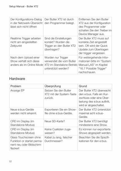
Der Konfigurations-Dialog in der Netzwerk-Übersicht lässt sich nicht öffnen
Der Butler XT2 ist durch den Programmer belegt.
Entfernen Sie den Butler XT2 aus der Konfiguration des Programmer oder schalten Sie den Treiber im Device Manager aus.
Realtime Trigger arbeiten nicht am eingestellten Zeitpunkt
Sind die Einstellungen korrekt? Wurden die Trigger an den Butler XT2 übertragen?
Der Butler XT2 muss auf korrekte Zeit eingestellt sein. Oft wird der Quick Update zum Übertragen der trigger vergessen.
Nach dem Upload einer Show verhält sich diese anders als im Online Mode
Wurden nur Trigger verwendet die vom Butler XT2 im Standalone Betrieb unterstützt werden?
Für weitergehende Infor-mationen bitte im “System Manual LAS” im Kapitel “16.7 Possible Trigger” nachschauen.
Hardware
Problem Überprüfung Grund
Anzeige EP Setzen Sie den Butler XT2 mit der System-Taste zurück.
Der Butler XT2 überwacht den e:bus. Falls ein Kur-zschluss oder eine Über-lastung des e:bus auftritt, wird er abgeschaltet.
Neue e:bus-Geräte werden nicht erkannt.
Exportieren Sie ein Show-file ohne e:bus-Geräte.
Der Butler XT2 ünterstützt maximal acht e:bus-Geräte.
CRD im Display (im Standalone-Modus)
Neue SD-Karte? Der Butler XT2 benötigt mindestens eine Show.
CRD im Display (im Standalone-Modus)
Keine Cuelisten zuge- wiesen?
Es können nur exportierte Shows abgespielt werden.
Glass Touchscreen ohne Funktion or startet perma-nent neu oder Bildschirm flackert
Kabel zu lang, falscher Durchmesser?
Beachten Sie die Spezifi-kationen für den e:bus.

53
Setup Manual - Butler XT2
Appendix

54
Setup Manual - Butler XT2
Change logFirmware Build Changes
2.0.3308 2016-09-19 NEW: HTTP ERROR 404 included NEW: RTC adjustments included 2.0.1527 2013-08-16 FIX: respond with random timeout to who is there requests - better load ballance in large installations 2.0.1511 2013-07-01 New: Option support for HTTP access Control included. FIX: multiple events on one astro event with different offsets FIX: V-Master setup before cuelist started fixed 2.0.1326 2013-02-27 FIX: Actionpads with more than 45 buttons FIX: Valid from/to settings for triggers 2.0.1237 2012-10-08 NEW: Web Configuration support NEW: Actionpad support NEW: UPNP support FIX: Release action for drycontacts

55
Setup Manual - Butler XT2
Dimensions/AbmessungenAll dimensions in mm/in Alle Abmessungen in mm/in
177
mm
/6.9
7 in
ch
59.5 mm/2.34 inch
75.4
mm
/2.3
4 in
ch

56
Setup Manual - Butler XT2
Connection diagram/Verbindungsbeispiel

57
Setup Manual - Butler XT2
Notes
58
Setup Manual - Butler XT2
Notes

59
Setup Manual - Butler XT2

For more information visit www.ecue.com