butterfly valve 27 series gearbox - sodeco valves
TRANSCRIPT

www.sodeco-valves.com1 04/09/2017
H2
H3
ØR
DN
L
B
H1
DN L B XR H1 H2 H3 ØR Kg
40 33 220 XR-05 145 27 26 100 4,91
50 43 241 XR-05 161 27 26 100 4,91
65 46 264 XR-05 175 27 26 100 5,31
80 46 276 XR-05 181 27 26 100 5,81
100 52 314 XR-05 200 27 26 100 10,22
125 56 340 XR-05 213 27 26 100 12,12
150 56 365 XR-06 226 27 32 160 15,52
200 60 435 XR-08 260 28 39 200 20,77
250 68 495 XR-08 292 28 39 200 28,37
300 78 579 XR-08 337 28 39 200 41,57
Sub
ject
to
ch
an
ge
s
BUTTERFLY VALVE 27 SERIESGearbox
OPTIONS: Limit switches, locking device, chain wheel, ...
DIMENSIONS: (mm)
The gearbox is calculated with a safety factor of 30% and max. differential pressure of 16 bar.For standard working conditions.
FIGURE: 27234ER: Seat in EPDM, with gearbox 27234BR: Seat in Buna, with gearbox 27234VR: Seat in Viton, with gearbox

www.sodeco-valves.com1 26/01/2017
Sub
ject
to
ch
an
ge
s
GENERAL FEATURES: Type: Lug Face-to-face: API609, BS EN 558, DIN3202, ISO 5752 Flange: DIN, BS, UNI, ISO, ANSI, AS, JIS Mounting flange: ISO5211 Working pressure: PN 16 (DN40 ~ DN150), PN10 (DN200 ~ DN300), 150 PSILugs threaded according to ISO 7005-1 (DIN PN 16) or according to ASME B16.5 (ANSI and DIN PN 20) Application: HVAC, water supply & sewage, food & beverage, Chemical and petrochemical processing Power and utilities Paper and pulp, ship building
BUTTERFLY VALVE 27 SERIESGeneral features
DESIGN STANDARDS
Standards ISO 5752, API 609
Compliance DIN 3202, API 609, BS EN 558
Actuator mounting flange ISO 5211
Marking ISO 5209
TESTS AND CERTIFICATES
PED/CE 97/23/EC
ATEX 2 GD
Pressure test API 598

www.sodeco-valves.com2 26/01/2017
Sub
ject
to
ch
an
ge
s
Retaining system The shaft is retained in the body with a retaining ring, a thrust washer and two C-rings, providing a “blow-out proof” shaft assembly. The retaining ring may be easily removed with a standard hand tool on field assembly.
Shaft One-piece through shaft ensures dependability and positive disc positioning.
Bushings Shaft bushings reduce torque and isolate the shaft from the valve body, preventing seizure of the shaft due to corrosion in the shaft journal.
Seat / Body The tongue-and-groove seat to body retention method make field replacement simple and fast. The resilient seat features lower torque and eliminates the need for flange gaskets.
Disc and shaft connection The spline or square connection eliminates shaft retention components being exposed to the line media, maximum flow is achieved.
Mounting flange ISO 5211 mounting flange
accommodates direct mounting of all types of actuators,
including handles, gear operators, electric and pneumatic actuators
O-ring Shaft seal provides further
assurance against shaft leakage.
Hub seal Smooth finished disc flats
mate with seat flats to give a highly efficient primary seal
that prevents leakage into the shaft area.
Disc Precision profile provides
bubble-tight shut-off, assures minimum torque and longer
seat life.
BUTTERFLY VALVE 27 SERIESGeneral features
www.sodeco-valves.com3 26/01/2017
1
4
2
3
5
6
Sub
ject
to
ch
an
ge
s
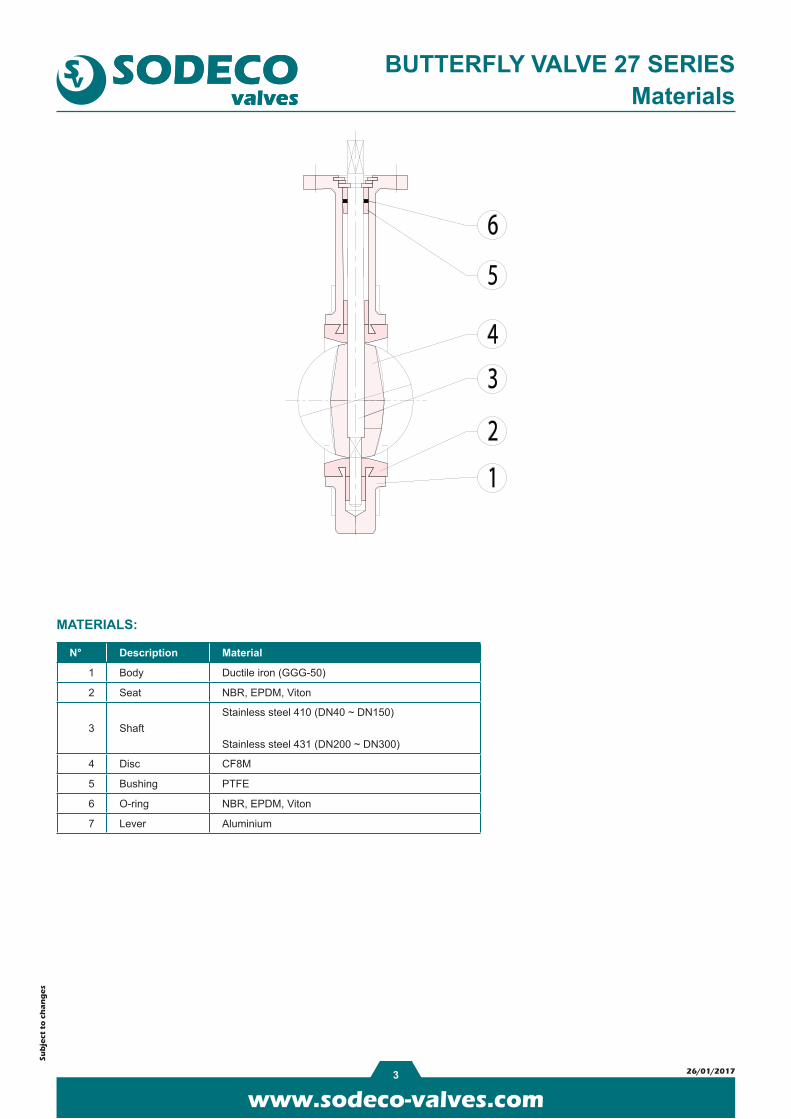
BUTTERFLY VALVE 27 SERIESMaterials
MATERIALS:
N° Description Material
1 Body Ductile iron (GGG-50)
2 Seat NBR, EPDM, Viton
3 ShaftStainless steel 410 (DN40 ~ DN150)
Stainless steel 431 (DN200 ~ DN300)
4 Disc CF8M
5 Bushing PTFE
6 O-ring NBR, EPDM, Viton
7 Lever Aluminium

www.sodeco-valves.com4 26/01/2017
BA
DN
F
H
ØD1
n-M
C
E
4 x Ød
P
DN Ø A B C F H P E dANSI 150 DIN PN 10 DIN PN 16
KgØD1 n-M ØD1 n-M ØD1 n-M
40 1 1/2" 145 75 33 211 221 9 70 9 98,5 4-5/8" 110 4-M16 110 4-M16 4,1
50 2" 161 80 43 211 237 11 70 9 120,5 4-5/8" 125 4-M16 125 4-M16 4,1
65 21/2" 175 89 46 211 251 11 70 9 139,5 4-5/8" 145 4-M16 145 4-M16 4,5
80 3" 181 95 46 211 257 11 70 9 152,5 4-5/8" 160 8-M16 160 8-M16 5,1
100 4" 200 114 52 258 285 11 70 9 190,5 8-5/8" 180 8-M16 180 8-M16 9,4
125 5" 213 127 56 258 298 14 70 9 216,0 8-3/4" 210 8-M16 210 8-M16 11,3
150 6" 226 139 56 258 311 14 70 9 241,5 8-3/4" 240 8-M20 240 8-M20 14,6
200 8" 260 175 60 395 330 17 70 12 298,5 8-3/4" 295 8-M20 295 12-M20 19,2
250 10" 292 203 68 395 362 22 102 12 362,0 12-7/8" 350 12-M20 355 12-M24 27,8
300 12" 337 242 78 395 407 22 102 12 432,0 12-7/8" 400 12-M20 410 12-M24 41,0
Sub
ject
to
ch
an
ge
s
BUTTERFLY VALVE 27 SERIESDimensions
DIMENSIONS: (mm)

www.sodeco-valves.com5 26/01/2017
DN Kv (m³/h) T (Nm) 10 bar T (Nm) 16 bar
40 115 - 10
50 115 - 14
65 188 - 16
80 258 - 28
100 513 - 55
125 874 - 62
150 1350 - 95
200 2681 170 190
250 4566 300 350
300 7054 350 450
Sub
ject
to
ch
an
ge
s
BUTTERFLY VALVE 27 SERIESHow to order
TYPE BODY STEM DISC SEAT ACTUATOR = fix
27 2 3 4 V H
TYPE
17 Wafer - PN 10/16 - ANSI 150
27
Lug - PN 10/16 (DN40 - DN150)
Lug - PN10 (DN200 - DN300)
ANSI - on request
BODY
2 Ductile iron GGG-50 Rilsan coated
STEM
3Stainless steel AISI 410 (DN40 - DN150)
Stainless steel AISI 431 (DN200 - DN300)
DISC
4 Stainless steel CF8M
SEAT
E EPDM (T: -20°C - 110°C)
B Buna N (T: -10°C - 80°C)
V Viton (T: -10°C - 135°C)
ACTUATORS
- Free stem
H Handle
R Gearbox
Kv VALUES, BREAK AWAY TORQUE:

www.sodeco-valves.com1 14/10/2016
Sub
ject
to
ch
an
ge
s
GENERAL FEATURES:- Quarter turn gearbox for the operation of ball, butterfly and plug valves - Body in cast aluminium - Mounting flange acc. to ISO 5211- Removable stem drive inserts for 45° and 90° positions - Temperature range: -20°C ~ +120°C - Built in mechanical stops - IP 65
GEARBOXFIG. XR
Type Ratio Output torque (Nm) Input torque (Nm) Kg
232-005 40 : 1 125 12,5 0,8
232-006 40 : 1 250 25 0,9
232-008 37 : 1 500 41,7 1,55
232-011 45 : 1 900 75 2,9
232-013 40 : 1 1000 83 5,4

www.sodeco-valves.com2 14/10/2016
Sub
ject
to
ch
an
ge
s
Materials - FIG. XR
MATERIALS:
Pos. Description Material
1 Shaft Steel
2 Body Cast aluminium
3 Worm Carbon steel C45
4 Screws Steel ELVZ 8.8
5 Insert Sintered steel
6 Quadrant Ductile iron GGG 40
7 Coverplate Cast aluminium
8 Screws Steel ELVZ 8.8
9 Position indicator Polypropylene
GEARBOX

www.sodeco-valves.com3 14/10/2016
A
E
L
G
ISO
521
1
F
K
BC
D
Sub
ject
to
ch
an
ge
s
Dimensions - FIG. XR
DIMENSIONS: (mm)
GEARBOX
Type A B C D E F G ØK L ISO 5211 Handwheel
232-005 80 114 42,5 48 105 53 27 12 14 F05 - F07 PS 100
232-006 80 114 42,5 48 155 59 27 12 14 F05 - F07 PS 160
232-008 100 131 50 56 170 67 28 12 14 F07 - F10 PS 200
232-011 146 174 60 79 200 79 38 15 14 F10 - F12 PS 250
232-013 175 209 80 83 280 85 76,5 20 24 F10 - F12 / F14 SG 500

www.sodeco-valves.com4 14/10/2016
R
ØK ØK
Sub
ject
to
ch
an
ge
s
Handwheels - FIG. XRINSERTS
GEARBOX
HANDWHEELS
Gearbox type Insert type ØA S
232-005 005VK08 25 8
232-005 005VK09 25 9
232-005 005VK11 25 11
232-005 005VK14 25 14
232-006 006VK14 32,15 14
232-006 006VK17 32,15 17
232-008 010VK17 45,3 17
232-008 010VK19 45,3 19
232-008 010VK22 45,3 22
232-008 010VK24 45,3 24
232-008 010VK27 45,3 27
232-011 150VK17 60 17
232-011 150VK19 60 19
232-011 150VK22 60 22
232-011 150VK27 60 27
232-011 150VK30 60 30
232-011 150VK36 60 36
Type PS ØK ØA B Type SG ØK ØA B
PS100-12 12 100 35 SG150-12 12 150 80
PS125-12 12 125 34 SG150-15 15 150 80
PS125-15 15 125 48 SG200-12 12 200 80
PS160-12 12 160 48 SG200-15 15 200 80
PS160-15 15 160 49 SG250-12 12 250 110
PS200-12 12 200 51 SG250-15 15 250 110
PS200-15 15 200 52 SG300-12 12 300 115
PS250-12 12 250 63 SG300-15 15 300 115
PS250-15 15 250 63 SG400-20 20 400 130
SG500-20 20 500 150