butterfly valve, metal - gemu-group.com€¦ · butterfly valve, metal construction gemÜ type d480...
TRANSCRIPT

D480, D481, D487, D488
GEMÜ D487
GEMÜ D481
GEMÜ D488
GEMÜ D480
Sectional drawing
Butterfly Valve,Metal
Construction GEMÜ type D480 is a butterfly valve with various versions. It is available in nominal sizes DN 25 – 1600, various body versions (Wafer, Lug and U section) and in a large number of seal and body materials. It can be supplied with various operators: hand lever or gearbox, pneumatic actuator or motorized on/off or control actuator.
Features• Suitable for gaseous and liquid media in industrial applications as well
as water treatment• Installation length acc. to ISO 5752/20, EN 558-1/20,
API 609 category A• Top flange acc. to EN ISO 5211• Max. operating pressure 10/16/25 bar• Connection standards: PN 10, PN 16,
ASME B16.47 Series A Class 150, ASME B16.5 Class 150• Valve acc. to EN 593• Leak test acc. to EN 12266-1/P12 leakage rate A• The butterfly valve complies with the safety requirements of Annex I
of the European Pressure Equipment Directive 2014/34/EU for fluids of group 1 and 2
2D480,D481,D487,D488
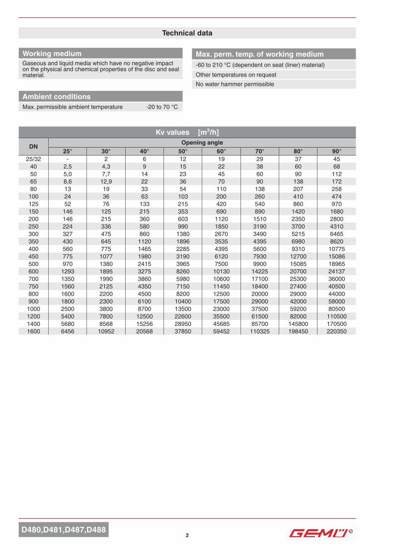
Technical data
Max. perm. temp. of working medium-60 to 210 °C (dependent on seat (liner) material)Other temperatures on requestNo water hammer permissible
Working mediumGaseous and liquid media which have no negative impact on the physical and chemical properties of the disc and seal material.
Ambient conditionsMax. permissible ambient temperature -20 to 70 °C
Kv values [m³/h]
DN Opening angle25° 30° 40° 50° 60° 70° 80° 90°
25/32 - 2 6 12 19 29 37 4540 2,5 4,3 9 15 22 38 60 6850 5,0 7,7 14 23 45 60 90 11265 8,6 12,9 22 36 70 90 138 17280 13 19 33 54 110 138 207 258
100 24 36 63 103 200 260 410 474125 52 76 133 215 420 540 860 970150 146 125 215 353 690 890 1420 1680200 146 215 360 603 1120 1510 2350 2800250 224 336 580 990 1850 3190 3700 4310300 327 475 860 1380 2670 3490 5215 6465350 430 645 1120 1896 3535 4395 6980 8620400 560 775 1465 2285 4395 5600 9310 10775450 775 1077 1980 3190 6120 7930 12700 15086500 970 1380 2415 3965 7500 9900 15085 18965600 1293 1895 3275 8260 10130 14225 20700 24137700 1350 1990 3860 5980 10600 17100 25300 36000750 1560 2125 4350 7150 11450 18400 27400 40500800 1600 2200 4500 8200 12500 20000 29000 44000900 1800 2300 6100 10400 17500 29000 42000 58000
1000 2500 3800 8700 13500 23000 37500 59200 805001200 5400 7800 12500 22600 35500 61500 82000 1105001400 5680 8568 15256 28950 45685 85700 145800 1705001600 6456 10952 20568 37850 59452 110325 198450 220350

D480,D481,D487,D4883
Torques dependent on the material combination [Nm]
Torques dependent on the material combination [Nm]Torque values valid for optimal operating conditions, 20 °C, lubricious liquids
Technical data
Material (code) Operating pressure Nominal size
Disc Seat (liner) PS
DN25/32 40 50 65 80 100 125 150 200 250 300 350
A, B, D, E, G, H, K
E, N
3 bar 5 5 5 15 17 22 39 48 90 126 161 2456 bar 6 6 7 16 20 29 46 75 120 210 270 300
10 bar 9 9 13 20 23 42 72 90 140 270 390 50016 bar 15 15 17 25 28 50 85 110 215 350 560 950
A, C, D, F, G, H, J, K, O, P, R, S,
V, W, Z
3 bar 6 6 6 18 20 26 47 58 108 151 193 2946 bar 7 7 8 19 24 35 55 90 144 252 324 360
10 bar 11 11 16 24 28 50 86 108 168 324 468 60016 bar 18 18 20 30 34 60 102 132 258 420 672 1140
C, F, N, P, R
E, N
3 bar 6 6 6 18 20 26 47 58 108 151 193 2946 bar 7 7 8 19 24 35 55 90 144 252 324 360
10 bar 11 11 16 24 28 50 86 108 168 324 468 60016 bar 18 18 20 30 34 60 102 132 258 420 672 1140
A, C, D, F, G, H, J, K, O, P, R, S,
V, W, Z
3 bar 7 7 7 22 24 32 56 69 130 181 232 3536 bar 9 9 10 23 29 42 66 108 173 302 389 432
10 bar 13 13 19 29 33 60 104 130 202 389 562 72016 bar 22 22 24 36 40 72 122 158 310 504 806 1368
Material (code) Operating pressure Nominal size
Disc Seat (liner) PS
DN400 450 500 600 700 750 800 900 1000 1200 1400 1600
A, B, D, E, G, H, K
E, N
3 bar 520 590 840 1000 1650 1800 2300 4700 6500 8500 14000 220006 bar 600 1120 1390 2200 3300 3500 4600 6800 8500 12000 17000 26000
10 bar 700 1450 1800 3450 5000 5500 6500 8500 11500 15500 19500 3000016 bar 1000 1950 2500 3800 5860 6000 9500 11500 15000 22000 - -
A, C, D, F, G, H, J, K, O, P, R, S,
V, W, Z
3 bar 624 708 1008 1200 1980 2160 2760 5640 7800 10200 16800 264006 bar 720 1344 1668 2640 3960 4200 5520 8160 10200 14400 20400 31200
10 bar 840 1740 2160 4140 6000 6000 7800 10200 13800 18600 23400 3600016 bar 1200 2340 3000 4560 7032 7200 11400 13800 18000 26400 - -
C, F, N, P, R
E, N
3 bar 624 708 1008 1200 1980 2160 2760 5640 7800 10200 16800 264006 bar 720 1344 1668 2640 3960 4200 5520 8160 10200 14400 20400 31200
10 bar 840 1740 2160 4140 6000 6000 7800 10200 13800 18600 23400 3600016 bar 1200 2340 3000 4560 7032 7200 11400 13800 18000 26400 - -
A, C, D, F, G, H, J, K, O, P, R, S,
V, W, Z
3 bar 749 850 1210 1440 2376 2592 3312 6768 9360 12240 20160 316806 bar 864 1613 2002 3168 4752 5040 6624 9792 12240 17280 24480 37440
10 bar 1008 2088 2592 4968 7200 7200 9360 12240 16560 22320 28080 4320016 bar 1440 2808 3600 5472 8438 8640 13680 16560 21600 31680 - -

4D480,D481,D487,D488
Order data
1 Type CodeButterfly valve with bare shaft D480Butterfly valve with pneumatic actuator D481Butterfly valve with manual operator D487Butterfly valve with motorized actuator D488
3 Body configuration CodeWafer (DN 25 - 1200) WLug (DN 25 - 1000) LU section (DN 200 - 1600) U
2 Nominal size CodeDN 25 25DN 32 32DN 40 40DN 50 50DN 65 65DN 80 80DN 100 100DN 125 125DN 150 150DN 200 200DN 250 250DN 300 300DN 350 350DN 400 400DN 450 450DN 500 500DN 600 600DN 700 700DN 750 750DN 800 800DN 900 900DN 1000 1T0DN 1200 1T2DN 1400 1T4DN 1600 1T6
4 Operating pressure
DN PS 3bar PS 6bar PS 10bar PS 16barCode
200 0 1 2 3250 0 1 2 3300 0 1 2 3350 0 1 2 3400 0 1 2 3450 0 1 2 3500 0 1 2 3600 0 1 2 3700 0 1 2 3750 0 1 2 3800 0 1 2 3900 0 1 2 3
1000 0 1 2 31200 0 1 2 31400 0 1 21600 0 1 2
Standard PS 25 on request
5 Connection
DNWafer Lug U section
PN 6 PN 10 PN 16 PN 10 PN 16 PN 10 PN 16Code Code Code
25 3 3 3 3 332 3 3 3 3 340 3 3 3 3 350 3 3 3 365 3 3 3 3 380 3 3 3 3 3
100 3 3 3 3 3125 3 3 3 3 3150 3 3 3 3 3 2200 3 3 3 2 3 2 3250 3 3 3 2 3 2 3300 3 3 3 2 3 2 3350 3 3 2 3 2 3400 3 3 2 3 2 3450 2 3 2 3 2 3500 2 3 2 3 2 3600 2 3 2 3 2 3700 2 3 2 3 2 3750 2 3 2 3 2 3800 2 3 2 3 2 3900 2 3 2 3 2 3
1000 2 3 2 3 2 31200 2 3 2 31400 2 31600 2 3StandardFor further connections see availability on page 12
4 Operating pressure
DN PS 3bar PS 6bar PS 10bar PS 16barCode
25 0 1 2 332 0 1 2 340 0 1 2 350 0 1 2 365 0 1 2 380 0 1 2 3
100 0 1 2 3125 0 1 2 3150 0 1 2 3

D480,D481,D487,D4885
8 Shaft material CodeAISI 420 / 1.4021 1AISI 316 / 1.4401 (max. operating pressure PS 10 bar) 21.4462 Duplex 4
10 Liner fixing CodeLoose liner (standard) LBonded liner (to DN 400) BVulcanized liner (to DN 1000) V
6 Body material CodeEN-GJS-400-15 (GGG 40), Epoxy coated, DN 25 - 600 2EN-GJL-250 (GG 25), Epoxy coated, DN 700 - 1600 1EN-GJS-400-18-LT (GGG 40.3), Epoxy coated, DN 25 - 300, body configuration Lug 3ASTM A351, CF8M, cast stainless steel 1.4408 4ASTM A216 WCB, cast steel 5ASTM A352 LCC, cast steel LS 275 JR + Epox laminated carbon steel 9EN-AC-46100 / EN-AC-47100, cast aluminium 0
11 Control function CodeButterfly valve with bare shaft type D480 FButterfly valve with manual operator type D487 0Normally closed (NC), type D481 1Normally open (NO), type D481 2Double acting (DA), type D481 3
13 Operator size CodeD480 (column 12) see page 13D481 (column 12) see page 17D487 (column 12) see page 14/15D488 (column 13/14/15) see page 22
Order data
7 Disc material CodeCF8M, 1.4408 ACF8M, 1.4408 polished BEN-GJS-400-15 (GGG 40), Halar coated PCF8M, 1.4408 Halar coated C1.4469 Super Duplex DEN-GJS-400-15 / GGG40, Epoxy coated (Resicoat) EEN-GJS-400-15 / GGG40, rubberlinedEPDM(≤DN600) FEN-GJS-400-15(GGG40)(≤DN600) rubber lined Flucast AB/P NEN-GJS-400-15, GGG40 Rilsan® PA11coated(≤DN600) RCastbronze:DIN1705(Rg10)(≤DN300), UNEEN1982(CuAl10FeNi5C)(≥DN350) GURANUS B6, 1.4539 (similar 904L) K2.4602,Alloy22(NiCr21Mo14W)(≤DN200) H
9 Seat (liner) material CodeEPDM -20...+ 110 °C EEPDM KP / FDA -10...+ 130 °C Z (not vulcanizable)EPDM (ACS, WRAS, DVGW water approval) -20...+ 95 °C WNBR LT -20... + 90 °C 2NBR -10... + 90 °C NNBR (DVGW Gas) -10... + 90 °C JHNBR -10 ... +100 °C AFPM -15 ... +210 °C VFPM GF -15 ... +210 °C DFPM - BIO -5 ... +200 °C OAB/P - SBR (abrasion-resistant) -10 ... + 70 °C FAB/E - EPDM (abrasion-resistant) -10 ... + 90 °C GAB/N - NBR (abrasion-resistant) 0 ... + 90 °C KAB/T - EPDM-HT (abrasion-resistant) -5 ... +130 °C BSilicone (steam) -60 ... +140 °C R (red. operating press. max. 10 bar)Silicone -60 ... +200 °C SHypalon -25 ... +120 °C HEpichlorhydrine -40 ... +125 °C CNeoprene -25 ... + 80 °C P
12 Special function CodeACS A*DVGW water D*WRAS W** only seat (liner) material Code W
Order example 1 2 3 4 5 6 7 8 9 10 11 12 13Code D480 50 W 3 3 2 A 1 E L F - 07 D11Other designs and materials on request

6D480,D481,D487,D488
Pos. Bearing1 Body2 Bearing3 O-ring4 Shaft5 Seat (liner)6 Disc7 Lower axis8 Circlip9 Washer
10 Plug11 Circlip12 O-ring13 O-ring14 Bearing
* not body material- cast aluminium (code 0)
Parts list

7
□F
øD
øJ
øQøR
L ±1
AE
B
ES
øT
C
øK
øG
DN 32-450
H
ES
øTøF
bh
a
Position
CLOSED
OPEN
□F
øP
D480,D481,D487,D488
DN a b h700 18 11 7
750-1100 22 14 91200 28 16 10
Body dimensions [mm]
Shaft connection Square, diagonal DN 25 - 500
Shaft connection Round with single keyway DN 600 - 1200
Body configuration - Wafer (code W) DN A B C D E G øa H J K L ISO P Q R S T Weightt
[kg]25 102.5 60.2 33 68 18 □11 90 15 100.0 85.0 8 F07 13.0 70 4x9 1.532 102.5 60.2 33 68 18 □11 90 15 100.0 85.0 8 F07 13.0 70 4x9 1.540 110.0 56.0 33 76 18 □11 90 26 110.0 95.0 10 F07 13.0 70 4x9 1.750 120.0 61.5 43 100 18 □11 90 30 125.0 120.6 10 F07 13.0 70 4x9 2.465 135.0 69.0 46 108 18 □11 90 47 145.0 127.0 10 F07 13.0 70 4x9 2.780 141.0 94.0 46 124 18 □11 90 66 160.0 145.0 10 F07 13.0 70 4x9 3.2
100 165.0 106.0 52 147 18 □11 90 90 185.5 165.0 10 F07 13.0 70 4x9 4.0125 180.0 126.5 56 180 18 □14 90 113 225.0 206.0 12 F07 17.0 70 4x9 6.2150 193.0 133.0 56 206 18 □14 90 139 241.3 229.0 12 F07 17.0 70 4x9 7.3200 225.0 170.0 60 257 24 □17 90 193 305.0 280.0 12 F07 20.3 70 4x9 11.1250 282.5 210.0 68 324 32 □22 130 241 362.0 335.0 14 F10 26.2 102 4x12 3 70 20.2300 308.0 240.0 78 376 32 □22 130 290 431.8 394.0 14 F10 26.2 102 4x12 3 70 29.6350 338.5 263.0 78 430 32 □22 160 338 476.3 445.0 15 F10 28.0 102 4x12 3 70 35.2400 380.0 308.0 102 485 28 □27 160 387 540.0 510.0 18 F12 33.0 125 4x14 4 85 55.5450 380.5 340.0 114 536 37 □36 190 437 20 F14 48.0 140 4x18 4 100 79.7500 432.5 380.0 127 593 37 □36 210 478 20 F14 48.0 140 4x18 4 100 114.0600 494.0 440.0 154 690 47 □46 210 578 24 F16 165 4x22 5 130 170.9700 590.0 490.0 165 830 106 Ø65 300 678 30 F25 254 8x18 5 200 252.9750 590.0 530.0 190 836 106 Ø80 300 703 25 F25 254 8x18 5 200 294.9800 630.0 565.0 190 902 106 Ø80 300 767 28 F25 254 8x18 5 200 346.5900 695.0 610.0 203 1010 110 Ø80 350 867 32 F25 254 8x18 5 200 459.5
1000 770.0 675.0 216 1116 110 Ø80 350 964 32 F25 254 8x18 5 200 580.71200 875.0 818.0 254 1334 110 Ø100 350 1158 40 F30 298 8x23 5 230 963.3

8D480,D481,D487,D488
øD
øa
øJ
L ±1
AE
B
H
ES
øT
G
øP
G
ES
øTG
bh
a
Position
CLOSED
OPEN
DN a b h700 18 11 7
750-1000 22 14 9
Body dimensions [mm]
Shaft connection Square, diagonal DN 25 - 500
Shaft connection Round with single keyway DN 600 - 1000
Body configuration - Lug (code L)DN A B C D E G øa H J L ISO P Q R S T Weight
[kg]25 102.5 50.4 33 68 18 □11 90 15 130 8 F07 13.0 70 4x9 1.932 102.5 50.4 33 68 18 □11 90 15 130 8 F07 13.0 70 4x9 1.940 110.0 54.0 33 76 18 □11 90 26 140 10 F07 13.0 70 4x9 2.050 120.0 59.5 43 100 18 □11 90 30 156 10 F07 13.0 70 4x9 2.965 135.0 66.5 46 108 18 □11 90 47 175 10 F07 13.0 70 4x9 3.3
80 141.0 91.0 46 124 18 □11 90 66 194 10 F07 13.0 70 4x9 4.8185 3.5
100 165.0 105.0 52 147 18 □11 90 90 224 10 F07 13.0 70 4x9 6.3125 180.0 125.0 56 180 18 □14 90 113 267 12 F07 17.0 70 4x9 9.8150 193.0 136.5 56 206 18 □14 90 139 292 12 F07 17.0 70 4x9 10.6
200 225.0 156.0 60 257 24 □17 90 193 334 12 F07 20.3 70 4x9 13.4171.0 352 17.5
250 282.5 210.0 68 324 32 □22 130 241 409 14 F10 26.2 102 4x12 3 70 26.4300 308.0 240.0 78 376 32 □22 130 290 480 14 F10 26.2 102 4x12 3 70 39.6350 338.5 263.0 78 430 32 □22 160 338 522 18 F10 28.0 102 4x12 3 70 56.1400 380.0 308.0 102 485 28 □27 160 387 595 17 F12 33.0 125 4x14 4 85 74.9
450 380.5 340.0 114 536 37 □36 190 437 633 20 F14 48.0 140 4x18 4 100 103.0638 94.6
500 432.5 380.0 127 593 37 □36 210 478 717 20 F14 48.0 140 4x18 4 100 158.0600 494.0 440.0 154 690 47 □46 210 578 833 24 F16 165 4x22 5 130 220.0
700 590.0 490.0 165 832 106 Ø65 300 678 904 30 F25 254 8x18 5 200 293.0924 312.0
750 590.0 530.0 190 836 106 Ø80 300 703 964 25 F25 254 8x18 5 200 373.0979 392.0
800 630.0 565.0 190 902 106 Ø80 300 767 1020 28 F25 254 8x18 5 200 432.0900 695.0 610.0 203 1010 110 Ø80 350 867 1120 32 F25 254 8x18 5 200 539.0
1000 770.0 675.0 216 1116 110 Ø80 350 964 1246 32 F25 254 8x18 5 200 690.0

9
E E
S S
øTøTøF
øG
øD
øQøR
L ±1
AE
BC
H
bh
a
Position
CLOSED
OPEN
□F
øP
□F
D480,D481,D487,D488
DN a b h700 18 11 7
750-1100 22 14 91200 28 16 10
1400, 1600 32 18 11
Body dimensions [mm]
Shaft connection Square, diagonal DN 25 - 600
Shaft connection Round with single keyway DN 700 - 1600
Body configuration - U section (code U)DN A B C D E G øa H L ISO P Q R S T Weight
[kg]150 193.0 143.0 56 285 19 □14 90 139 12 F07 17.0 70 4x9 11.0200 225.0 172.5 60 345 24 □17 90 193 12 F07 20.3 70 4x9 18.4250 282.5 210.0 68 406 32 □22 130 241 14 F10 26.2 102 4x12 3 70 30.8300 308.0 240.0 78 480 32 □22 130 290 14 F10 26.2 102 4x12 3 70 45.4350 338.5 268.0 78 535 32 □22 160 338 15 F10 28.0 102 4x12 3 70 54.4400 380.0 308.0 102 597 28 □27 160 387 18 F12 33.0 125 4x14 4 85 79.2450 380.5 340.0 114 640 37 □36 190 437 20 F14 48.0 140 4x18 4 100 99.9500 432.5 380.0 127 700 37 □36 210 478 20 F14 48.0 140 4x18 4 100 134.5600 494.0 440.0 154 834 47 □46 210 578 24 F16 165 4x22 5 130 216.4700 590.0 490.0 165 916 106 Ø65 300 678 30 F25 254 8x18 5 200 273.9750 590.0 530.0 190 995 106 Ø80 300 703 25 F25 254 8x18 5 200 348.9800 630.0 565.0 190 1065 106 Ø80 300 767 28 F25 254 8x18 5 200 395.5900 695.0 610.0 203 1120 110 Ø80 350 867 32 F25 254 8x18 5 200 511.5
1000 770.0 675.0 216 1290 110 Ø80 350 964 32 F25 254 8x18 5 200 704.71200 875.0 818.0 254 1485 120 Ø100 350 1158 40 F30 298 8x23 5 230 1094.01400 1000.0 969.0 280 1685 120 Ø120 350 1339 35 F30 298 8x23 5 230 1656.01600 1115.0 1090.0 318 1930 160 Ø130 475 1533 40 F40 406 8x39 8 300 2132.0

10D480,D481,D487,D488
e E e L
n
G
e E e
e E e L L
G
G L1A-A
n
B-B
nA-A
B
B
AA
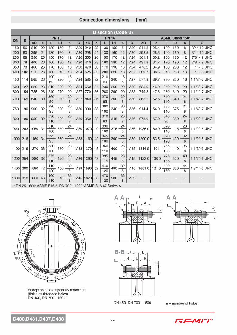
øD
Connection dimensions [mm]
n = number of screws
Flange holes are specially machined (finish as threaded holes) DN 450, DN 700 - 1200
Wafer (Code W)
DN E PN 10 PN 16 ASME Class 150*øD e L L1 n G øD e L L1 n G øD e L L1 n G
25 33 85 16 90 110 4 M12 85 16 90 110 4 M12 79.4 14.3 85 105 4 1/2″-13UNC32 33 100 16 90 110 4 M16 100 16 90 110 4 M16 88.9 17.5 90 110 4 1/2″-13UNC40 33 110 16 90 110 4 M16 110 16 90 110 4 M16 98.4 17.5 90 110 4 1/2″-13UNC50 43 125 18 100 120 4 M16 125 18 100 120 4 M16 120.6 19.0 100 120 4 5/8″-11UNC65 46 145 18 100 120 4 M16 145 18 100 120 4 M16 139.7 22.2 110 130 4 5/8″-11UNC80 46 160 20 110 130 8 M16 160 20 110 130 8 M16 152.4 23.8 110 130 4 5/8″-11UNC
100 52 180 20 110 130 8 M16 180 20 110 130 8 M16 190.5 23.8 120 140 8 5/8″-11UNC125 56 210 22 120 140 8 M16 210 22 120 140 8 M16 215.9 23.8 130 150 8 3/4″-10UNC150 56 240 22 130 150 8 M20 240 22 130 150 8 M20 241.3 25.4 130 150 8 3/4″-10UNC200 60 295 24 130 160 8 M20 295 24 130 160 12 M20 298.5 28.6 140 160 8 3/4″-10UNC250 68 350 26 150 170 12 M20 355 26 150 170 12 M24 361.9 30.2 160 180 12 7/8″-9UNC300 78 400 26 160 180 12 M20 410 28 160 180 12 M24 431.8 31.7 170 190 12 7/8″-9UNC350 78 460 26 170 180 16 M20 470 30 170 190 16 M24 476.2 34.9 180 200 12 1″-8UNC400 102 515 26 180 210 16 M24 525 32 200 220 16 M27 539.7 36.5 210 230 16 1″-8UNC
450 114 585 26 190 220 16 M24 585 32 210 240 16 M27 577.8 39.7 230 250 16 11/8″-7UNC60 8 60 8500 127 620 28 210 230 20 M24 650 34 230 260 20 M30 635.0 46.0 250 280 20 11/8″-7UNC600 154 725 28 240 270 20 M24 770 36 260 290 20 M33 749.3 47.6 280 310 20 11/4″-7UNC
700 165 840 30260
28020
M27 840 36270
30020
M33 863.5 52.5310
34024
11/4″-7UNC80 8 85 8 110 8
750 190 900 32290
32020
M30 900 38300
34520
M33 914.4 54.0335
37524
11/4″-7UNC95 8 100 8 110 8
800 190 950 32290
32020
M30 950 38310
34520
M36 978.0 57.0340
38024
11/2″-6UNC110 8 100 8 95 8
900 203 1050 34310
35024
M30 1050 40330
37524
M36 1086.0 60.0370
41528
11/2″-6UNC100 8 100 8 110 8
1000 216 1160 34325
36024
M33 1170 42345
39024
M39 1200.0 63.5390
43032
11/2″-6UNC95 8 100 8 120 8
1100 216 1270 38330
37028
M33 1270 48360
40028
M39 1314.5 101.0465
41036
11/2″-6UNC100 8 110 8 150 8
1200 254 1380 38 375 420 28 M36 1390 48 395 445 28 M45 1422.0 108.0 475 520 40 11/2″-6UNC110 8 115 8 165 8* DN 25 - 600: ASME B16.5; DN 700 - 1200: ASME B16.47 Series A

11D480,D481,D487,D488
e L
G
n
A-A
AA
øD
Connection dimensions [mm]
n = number of screws
Lug (Code L)
DN E PN 10 PN 16 ASME B16.5 Class 150øD e L n G øD e L n G øD e L n G
25 33 85 16 30 8 M12 85 16 30 8 M12 79.4 14.3 30 8 1/2″-13UNC32 33 100 16 30 8 M16 100 16 30 8 M16 88.9 17.5 30 8 1/2″-13UNC40 33 110 16 30 8 M16 110 16 30 8 M16 98.4 17.5 30 8 1/2″-13UNC50 43 125 18 35 8 M16 125 18 35 8 M16 120.6 19.0 35 8 5/8″-11UNC65 46 145 18 40 8 M16 145 18 40 8 M16 139.7 22.2 45 8 5/8″-11UNC80 46 160 20 40 16 M16 160 20 40 16 M16 152.4 23.8 45 8 5/8″-11UNC
100 52 180 20 45 16 M16 180 20 45 16 M16 190.5 23.8 45 16 5/8″-11UNC125 56 210 22 50 16 M16 210 22 50 16 M16 215.9 23.8 50 16 3/4″-10UNC150 56 240 22 50 16 M20 240 22 50 16 M20 241.3 25.4 50 16 3/4″-10UNC200 60 295 24 50 16 M20 295 24 50 24 M20 298.5 28.6 55 16 3/4″-10UNC250 68 350 26 60 24 M20 355 26 60 24 M24 361.9 30.2 60 24 7/8″-9UNC300 78 400 26 65 24 M20 410 28 65 24 M24 431.8 31.7 70 24 7/8″-9UNC350 78 460 26 65 32 M20 470 30 65 32 M24 476.2 34.9 70 24 1″-8UNC400 102 515 26 75 32 M24 525 32 80 32 M27 539.7 36.5 85 32 1″-8UNC
450 114 565 26 75 32 M24 585 32 80 32 M27 577.8 39.5 85 32 11/8″-7UNC60 8 60 8500 127 620 28 90 40 M24 650 34 65 40 M30 635.0 46.0 105 40 11/8″-7UNC600 154 725 28 100 40 M27 770 36 110 40 M33 749.3 47.6 120 40 11/4″-7UNC
700 165 840 30 110 40 M27 840 36 120 40 M33 863,5 - - - -80 8 85 8
750 190 900 32 130 40 M30 900 38 130 40 M33 914.4 54.0 150 48 11/4″-7UNC100 8 100 8 110 8
800 190 950 32 130 40 M30 950 38 130 40 M36 - - - - -110 8 110 8
900 203 1050 34 130 48 M30 1050 40 140 48 M36 - - - - -95 8 100 8
1000 216 1160 34 140 48 M33 1170 42 150 48 M39 - - - - -95 8 100 8
12D480,D481,D487,D488
DN 450, DN 700 - 1600
B
B
AA
øD e E e
e E e
L L
L L
G
G G
n n
n
A-A
B-B
A-A
Operator size - Type D480 - Butterfly valve with bare shaftConnection dimensions [mm]
n = number of holes
Flange holes are specially machined (finish as threaded holes) DN 450, DN 700 - 1600
U section (Code U)
DN E PN 10 PN 16 ASME Class 150*øD e L L1 n G øD e L L1 n G øD e L L1 n G
150 56 240 22 130 150 8 M20 240 22 130 150 8 M20 241.3 25.4 130 150 8 3/4″-10UNC200 60 295 24 130 160 8 M20 295 24 130 160 12 M20 298.5 28.6 140 160 8 3/4″-10UNC250 68 350 26 150 170 12 M20 355 26 150 170 12 M24 361.9 30.2 160 180 12 7/8″-9UNC300 78 400 26 160 180 12 M20 410 28 160 180 12 M24 431.8 31.7 170 190 12 7/8″-9UNC350 78 460 26 170 180 16 M20 470 30 170 190 16 M24 476.2 34.9 180 200 12 1″-8UNC400 102 515 26 180 210 16 M24 525 32 200 220 16 M27 539.7 36.5 210 230 16 1″-8UNC
450 114 565 26190
22016
M24 585 32210
24016
M27 577.8 39.7 230 250 16 11/8″-7UNC60 8 60 8500 127 620 28 210 230 20 M24 650 34 230 260 20 M30 635.0 46.0 250 280 20 11/8″-7UNC600 154 725 28 240 270 20 M27 770 36 260 290 20 M33 749.3 47.6 280 310 20 11/4″-7UNC
700 165 840 30 260 280 20 M27 840 36 270 300 20 M30 863.5 52.5 310 340 24 11/4″-7UNC80 8 85 8 110 8
750 190 900 32290
32020
M30 900 38300
34080
M36 914.4 54.0335
37524
11/4″-7UNC95 8 100 8 110 8
800 190 950 32290
32020
M30 950 38310
34520
M36 978.0 57.0340
38024
11/2″-6UNC110 8 80 8 95 8
900 203 1050 34310
35024
M30 1070 40330
37524
M36 1086.0 60.0370
41528
11/2″-6UNC100 8 100 8 110 8
1000 216 1160 34325
36024
M33 1160 42345
39024
M39 1200.0 63.5390
43032
11/2″-6UNC95 8 100 8 120 8
1100 216 1270 38330
37028
M33 1270 48360
40028
M39 1314.5 101465
41036
11/2″-6UNC100 8 110 8 150 8
1200 254 1380 38375
42028
M36 1390 48395
44528
M45 1422.0 108.0475
52040
11/2″-6UNC110 8 115 8 165 8
1400 280 1590 42 410 450 32 M39 1590 52 440 490 32 M45 1651.0 124.0 580 630 44 13/4″-5UNC120 8 120 8 160 8
1600 318 1820 46 460 510 36 M45 1820 58 470 530 36 M52 - - - - - -110 8 120 8* DN 25 - 600: ASME B16.5; DN 700 - 1200: ASME B16.47 Series A

13 D480,D481,D487,D488
Availability / code - Body configuration / connection
○ = on request
WaferNominal size
Flange 25 32 40 50 65 80 100 125 150 200 250 300 350 400 450 500 600 700 800 900 1000 1200PN 6 ○ 3 3 ○ 3 3 3 3 3 3 3 3 3 ○ ○ ○ ○ - ○ ○ ○ ○
PN 10 3 3 3 3 3 3 3 3 3 3 3 3 3 3 2 2 2 2 2 2 2 2PN 16 3 3 3 3 3 3 3 3 3 3 3 3 3 3 3 3 3 3 3 3 3 3
ASME B16.5 Class 150 ○ D D D D D D D D D D D D D D D D ○ - - ○ ○
ASME B16.47 Class 150 - - - - - - - - - - - - - - - - - ○ E E ○ ○
JIS 5k ○ K K - K K K K K K K K ○ ○ ○ ○ ○ ○ ○ ○ ○ ○JIS 10k ○ G G G G G G G G G G ○ G G G G G G ○ G G GJIS 16k ○ J J ○ ○ J J J ○ J ○ ○ ○ J J J J - J J J JBS 10 D ○ H ○ H H H H H H H ○ H H ○ H ○ ○ - - ○ - ○BS 10 E ○ S S S S S S S S S S S S S S S S S ○ S S S
AS 2129 Tab E ○ U U ○ U U U U U U U U U ○ U ○ ○ ○ ○ ○ ○ -
LugFlange 25 32 40 50 65 80 100 125 150 200 250 300 350 400 450 500 600
PN 6 1 1 1 1 1 1 ○ 1 1 1 1 1 1 1 1 ○ ○PN 10 3 3 3 3 3 3 3 3 3 2 2 2 2 2 2 2 2PN 16 3 3 3 3 3 3 3 3 3 3 3 3 3 3 3 3 3
ASME B16.5 Class 150 D D D D D D D D D D D D D D D D D
JIS 5k K K K - K K K K K K K K ○ K K K KJIS 10k G G G G G G G G G G G ○ G G G G ○JIS 16k J J J ○ ○ J J J ○ J ○ ○ J J ○ J ○BS 10 D H H H H H H ○ H H H ○ H H ○ ○ ○ ○BS 10 E S S S S S S S S S S S S S ○ S ○ ○
AS 2129 Tab E U U U U U U U U U U U U U ○ U ○ ○
U sectionFlange 200 250 300 350 400 450 500 600 700 800 900 1000 1200 1400
PN 6 ○ 1 ○ ○ ○ ○ ○ ○ - ○ ○ ○ ○ 1PN 10 2 2 2 2 2 2 2 2 2 2 2 2 2 2PN 16 3 3 3 3 3 3 3 3 3 3 3 3 3 3
ASME B16.5 Class 150 D D D D D D D D ○ - ○ - - -
ASME B16.47 Class 150 - - - - - - - - ○ E ○ E E E
JIS 5k ○ K ○ ○ ○ ○ K K ○ K ○ ○ ○ -JIS 10k G G ○ G G G G G G G G G G -JIS 16k J - J J J J J J - J J J J -BS 10 D H H H H ○ H ○ ○ - - H - - -BS 10 E S S S S ○ S ○ ○ - - S - - -
AS 2129 Tab E U U U U ○ U ○ ○ ○ U U U U -
1314D480,D481,D487,D488
E E
S S
øTøTøF
□F
øP
DN 32 - 600 DN 700 - 1200
øQ øQ
Order example 1 2 3 4 5 6 7 8 9 10 11 12Code D480 F 07 D11
Order data
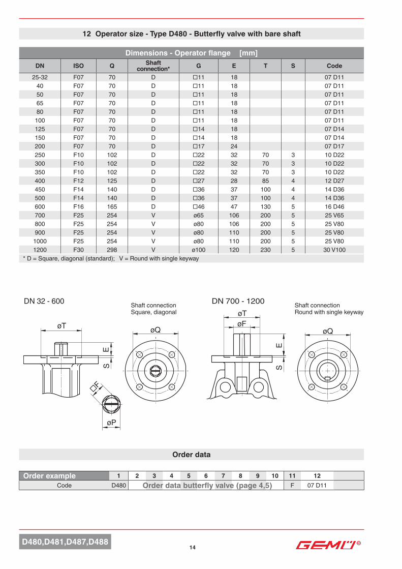
12 Operator size - Type D480 - Butterfly valve with bare shaft
Dimensions - Operator flange [mm]DN ISO Q Shaft
connection* G E T S Code
25-32 F07 70 D □11 18 07 D1140 F07 70 D □11 18 07 D1150 F07 70 D □11 18 07 D1165 F07 70 D □11 18 07 D1180 F07 70 D □11 18 07 D11
100 F07 70 D □11 18 07 D11125 F07 70 D □14 18 07 D14150 F07 70 D □14 18 07 D14200 F07 70 D □17 24 07 D17250 F10 102 D □22 32 70 3 10 D22300 F10 102 D □22 32 70 3 10 D22350 F10 102 D □22 32 70 3 10 D22400 F12 125 D □27 28 85 4 12 D27450 F14 140 D □36 37 100 4 14 D36500 F14 140 D □36 37 100 4 14 D36600 F16 165 D □46 47 130 5 16 D46700 F25 254 V ø65 106 200 5 25 V65800 F25 254 V ø80 106 200 5 25 V80900 F25 254 V ø80 110 200 5 25 V80
1000 F25 254 V ø80 110 200 5 25 V801200 F30 298 V ø100 120 230 5 30 V100
* D = Square, diagonal (standard); V = Round with single keyway
Shaft connection Square, diagonal
Shaft connection Round with single keyway
Order data butterfly valve (page 4,5)
15D480,D481,D487,D488
L
H
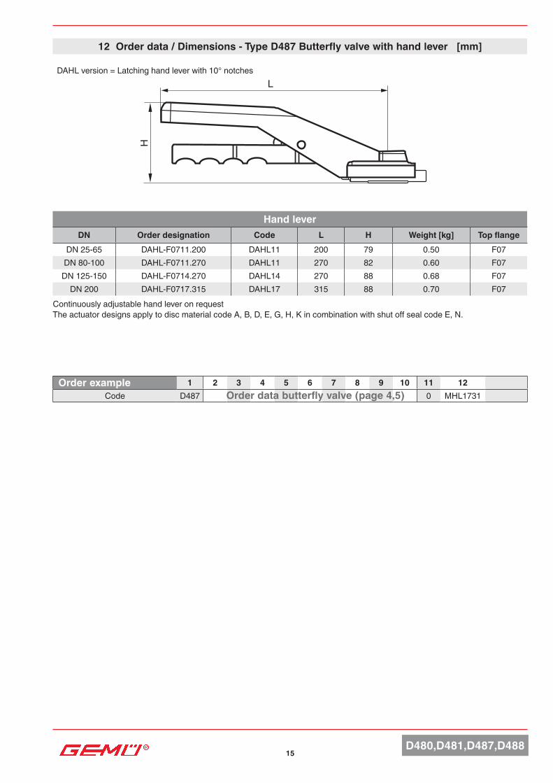
12 Order data / Dimensions - Type D487 Butterfly valve with hand lever [mm]
Hand leverDN Order designation Code L H Weight [kg] Top flange
DN 25-65 DAHL-F0711.200 DAHL11 200 79 0.50 F07DN 80-100 DAHL-F0711.270 DAHL11 270 82 0.60 F07
DN 125-150 DAHL-F0714.270 DAHL14 270 88 0.68 F07DN 200 DAHL-F0717.315 DAHL17 315 88 0.70 F07
Order example 1 2 3 4 5 6 7 8 9 10 11 12Code D487 0 MHL1731Order data butterfly valve (page 4,5)
DAHL version = Latching hand lever with 10° notches
Continuously adjustable hand lever on requestThe actuator designs apply to disc material code A, B, D, E, G, H, K in combination with shut off seal code E, N.

1316
EH Ø
R
B
15
CD
A
BC
D
ØA
H
E
ØR
GBMDV5 - 8 GB232 / GBMDV3 - 4 GBMDV5 - 8
12 Dimensions gear box/Code - valve with manual operator [mm]
Gearbox / handwheelDN Order designation Code A B C D E H øR n* Weight
[kg]DN 32-100 GB23205F05-F07 D11 PS100 GB232 80 114 42.5 48.0 105 53 100 10.0 0.8
DN 125 GB23205F05-F07 D14 PS100 GB232 80 114 42.5 48.0 105 53 100 10.0 0.8DN 150 GB23206F05-F07 D14 PS160 GB232 80 114 42.5 48.0 155 59 160 10.0 0.9DN 200 GB23206F05-F07 D17 PS160 GB232 80 114 42.5 48.0 155 59 160 10.0 0.9
DN 250-300 GB23208F07-F10 D22 PS200 GB232 100 131 50.0 56.0 170 67 200 9.3 1.4DN 350 GB23211F10-F12 D22 SG400 GB232 146 174 60.0 79.0 200 79 400 11.3 2.7DN 400 GB23211F10-F12 D27 SG400 GB232 146 174 60.0 79.0 200 79 400 11.3 2.7
DN 450 - 500 GBMDV3F12-F16 D36 SG400 GBMDV3 180 235 96.5 91.5 321 100 400 12.0 18.4DN 600 GBMDV4F16-F25 D46 SG500 GBMDV4 282 326 137.5 140.0 408 128 500 18.0 34.2DN 700 GBMDV4F16-F25 V65 SG500 GBMDV4 282 326 137.5 140.0 408 128 500 18.0 34.2DN 800 GBMDV5F16-F25 V80 SG600 GBMDV5 282 326 137.5 140.0 456 128 600 67.0 41.0
DN 900 - 1000 GBMDV7F25-F30 V80 SG700 GBMDV7 376 396 180 156.0 510 135 700 67.0 60.6DN 1200 GBMDV8F25-F30 V100 SG700 GBMDV8 376 396 180 156.0 579 135 700 162.0 66.4
Material: Aluminium, polyurethane coated n*: Handwheel turns OPEN/CLOSED
Order data 1 2 3 4 5 6 7 8 9 10 11 12Code D487 0 GB232Order data butterfly valve (page 4, 5)
The actuator designs apply to disc material code A, B, D, E, G, H, K in combination with shut off seal code E, N.

17D480,D481,D487,D488
Control mediumFiltered, dry compressed air, non-corrosive medium
Control pressure6 - 8 bar
Temperature range-40 to +80°C, other temperatures on request
Angle of rotation20° adjustable (75° - 95°) 90°
Technical data - GEMÜ D481 with pneumatic actuator Type DR/SC
Stroke limiter on request
Order example 1 2 3 4 5 6 7 8 9 10 11 12*Code D481 DU06AC0
*see page 18Order data butterfly valve (page 4, 5)
Technical data - GEMÜ D481 with pneumatic actuator Type ADA/ASR
Control mediumFiltered, dry compressed air, non-corrosive medium
Control pressure6 - 8 bar
Temperature range-30 to . +100°C, other temperatures on request
Angle of rotation±4° adjustable (86° - 94°) 90°
Order example 1 2 3 4 5 5 6 7 8 9 10 11*Code D481 BU08AC0Order data butterfly valve (page 4, 5)
Stroke limiter on request
*see page 16
12 Order data - GEMÜ D481 with pneumatic actuator Type ADA/ASR
12 Order data - GEMÜ D481 with pneumatic actuator Type DR/SC

18D480,D481,D487,D488
Actuator version* / Code - GEMÜ D481 with pneumatic actuator type ADA/ASROperating pressure 3 bar (see order data - operating pressure code 0)
DN Pneumatic double acting Code Pneumatic single acting Code25 ADA0020U F05 Y S14/S11 A BU02AB0 ASR0020U S08 F05 Y S14 A AU02FB032 ADA0020U F05 Y S14/S11 A BU02AB0 ASR0020U S08 F05 Y S14 A AU02FB040 ADA0020U F05 Y S14/S11 A BU02AB0 ASR0020U S08 F05 Y S14 A AU02FB050 ADA0020U F05 Y S14/S11 A BU02AB0 ASR0020U S08 F05 Y S14 A AU02FB065 ADA0020U F05Y S14/S11 A BU02AB0 ASR0040U S14 F05 Y S14/S11 A AU04KB080 ADA0020U F05 Y S14/S11 A BU02AB0 ASR0040U S14 F05 Y S14/S11A AU04KB0
100 ADA0080U F05F07 Y S17/S14 A BU08AC0 ASR0080U S14 F05F07 Y S17/S14 A AU08KC0125 ADA0080U F05F07 Y S17/S14 A BU08AC0 ASR0130U S14 F05F07 Y S17/S14 A AU13KC0150 ADA0080U F05F07 Y S17/S14 A BU08AC0 ASR0200U S14 F07F10 Y S17/S14 A AU20KE0200 ADA0130U F05F07 Y S 17/S14 A BU13AC0 ASR0300U S14 F07F10 Y S22 A AU30KD0250 ADA0300U F07F10 Y S22 A BU30AD0 ASR0500U S14 F10 Y S22 A AU50KF0300 ADA0300U F07F10 Y S22 A BU30AD0 ASR0500U S14 F10 Y S22 A AU50KF0350 ADA0300U F07F10 Y S22 A BU30AD0 ASR0850U S14 F10F12 Y S27 A AU85KG0400 ADA0850U F10F12 Y S27 A BU85AG0 ASR1750U S14 F14 Y S36 A A17UKK0450 ADA1200U F10F14 Y S36 A B12UAH0 ASR1750U S14 F14 Y S36 A A17UKK0500 ADA1200U F10F14 Y S36 A B12UAH0 ASR2100U S14 F14 Y S36 A A21UKK0600 ADA1200U F10F14 Y S36 A B12UAH0 ASR2500U S14 F16 Y S46 A A25UKL0
Operating pressure 6 bar (see order data - operating pressure code 1)25 ADA0020U F05 Y S14/S11 A BU02AB0 ASR0020U S08 F05 Y S14 A AU02FB032 ADA0020U F05 Y S14/S11 A BU02AB0 ASR0020U S08 F05 Y S14 A AU02FB040 ADA0020U F05 Y S14/S11 A BU02AB0 ASR0020U S08 F05 Y S14 A AU02FB050 ADA0020U F05 Y S14/S11 A BU02AB0 ASR0020U S08 F05 Y S14 A AU02FB065 ADA0020U F05 Y S14/S11 A BU02AB0 ASR0040U S14 F05 Y S14/S11 A AU04KB080 ADA0080U F05F07 Y S17/S14 A BU08AC0 ASR0080U S14 F05F07 Y S17/S14 A AU08KC0
100 ADA0080U F05F07 Y S17/S14 A BU08AC0 ASR0080U S14 F05F07 Y S17/S14 A AU08KC0125 ADA0080U F05F07 Y S17/S14 A BU08AC0 ASR0200U S14 F07F10 Y S17/S14 A AU20KE0150 ADA0080U F05F07 Y S17/S14 A BU08AC0 ASR0300U S14 F07F10 Y S22 A AU30KD0200 ADA0200U F07F10 Y S17/S14 A BU20AE0 ASR0500U S14 F07F10Y S22 A AU50KD0250 ADA0300U F07F10 Y S22 A BU30AD0 ASR0850U S14 F10F12 Y S27 A AU85KG0300 ADA0300U F07F10 Y S22 A BU30AD0 ASR0850U S14 F10F12 Y S27 A AU85KG0350 ADA0500U F10 Y S22 A BU50AF0 ASR1200U S14 F10F14 Y S36 A A12UKH0400 ADA0850U F10F12 Y S27 A BU85AG0 ASR1750U S14 F14 Y S36 A A17UKK0450 ADA1750U F14 Y S36 A B17UAK0 ASR2500U S14 F14 Y S36 A A25UK10500 ADA1750U F14 Y S36 A B17UAK0 ASR4000U S14 F16F25 Y S55 A A40UKM0600 ADA2500U F16 Y S46 A B25UAL0
Operating pressure 10 bar (see order data - operating pressure code 2))25 ADA0020U F05 Y S14/S11 A BU02AB0 ASR0020U S08 F05 Y S14 A AU02FB032 ADA0020U F05 Y S14/S11 A BU02AB0 ASR0020U S08 F05 Y S14 A AU02FB040 ADA0020U F05 Y S14/S11 A BU02AB0 ASR0020U S08 F05 Y S14 A AU02FB050 ADA0020U F05 Y S14/S11 A BU02AB0 ASR0040U S14 F05 Y S14/S11 A AU04KB065 ADA0080U F05F07 Y S17/S14 A BU08AC0 ASR0080U S14 F05F07 Y S17/S14 A AU08KC080 ADA0080U F05F07 Y S17/S14 A BU08AC0 ASR0080U S14 F05F07 Y S17/S14 A AU08KC0
100 ADA0080U F05F07 Y S17/S14 A BU08AC0 ASR0130U S14 F05F07 Y S17/S14 A AU13KC0125 ADA0080U F05F07 Y S17/S14 A BU08AC0 ASR0200U S14 F07F10 Y S17/S14 A AU20KE0150 ADA0130U F05F07 Y S17/S14 A BU13AC0 ASR0300U S14 F07F10 Y S22 A AU30KD0200 ADA0200U F07F10 Y S17/S14 A BU20AE0 ASR0500U S14 F07F10 Y S22 A AU50KD0250 ADA0300U F07F10 Y S22 A BU30AD0 ASR0850U S14 F10F12 Y S27 A AU85KG0300 ADA0500U F10 Y S22 A BU50AF0 ASR1200U S14 F10F14 Y S36 A A12UKH0350 ADA0850U F10F12 Y S27 A BU85AG0 ASR1750U S14 F14 Y S36 A A17UKK0400 ADA1200U F10F12 Y S27 A B12UAG0 ASR2100U S14 F14 Y S36 A A21UK10450 ADA2100U F14 Y S36 A B21UA10 ASR4000U S14 F16F25 Y S55 A A40UKM0500 ADA2100U F14 Y S36 A B21UA10
Operating pressure 16 bar (see order data - operating pressure code 3)25 ADA0020U F05 Y S14/S11 A BU02AB0 ASR0040U S14 F05 Y S14/S11 A AU04KB032 ADA0020U F05 Y S14/S11 A BU02AB0 ASR0040U S14 F05 YS14/S11 A AU04KB040 ADA0020U F05 Y S14/S11 A BU02AB0 ASR0040U S14 F05 YS14/S11 A AU04KB050 ADA0020U F05 Y S14/S11 A BU02AB0 ASR0040U S14 F05 YS14/S11 A AU04KB065 ADA0080U F05F07 Y S17/S14 A BU08AC0 ASR0080U S14 F05F07 Y S17/S14 A AU08KC080 ADA0080U F05F07 Y S17/S14 A BU08AC0 ASR0080U S14 F05F07 Y S17/S14 A AU08KC0
100 ADA0080U F05F07 Y S17/S14 A BU08AC0 ASR0200U S14 F07F10 Y S17/S14 A AU20KE0125 ADA0130U F05F07 Y S17/S14 A BU13AC0 ASR0300U S14 F07F10 Y S22 A AU30KD0150 ADA0130U F05F07 Y S17/S14 A BU13AC0 ASR0300U S14 F07F10 Y S22 A AU30KD0200 ADA0300U F07F10 Y S22 A BU30AD0 ASR0850U S14 F10F12 Y S27 A AU85KG0250 ADA0500U F10 Y S22 A BU50AF0 ASR1200U S14 F10F14 Y S36 A A12UKH0300 ADA0850U F10F12 Y S27 A BU85AG0 ASR1750U S14 F14 Y S36 A A17UKK0350 ADA1200U F10F12 Y S27 A B12UAG0 ASR2500U S14 F14 Y S36A A25UKK0400 ADA1750U F14 Y S36 A B17UAK0 ASR4000U S14 F16F25 Y S55 A A25UK10450 ADA2100U F14 Y S36 A B21UA10500 ADA2500U F16 Y S46 A B25UAL0
* Technical data for liquids +20 to +80°C with control pressure 6 barThe actuator designs apply to disc material code A, B, D, E, G, H, K in combination with shut off seal code E, N.

19D480,D481,D487,D488
D
L40 40
3015
15
ØT f8 XU
4 x M5x12
C
M6
2412 12
32
1616
M 5x12
G1/8
24 1212
321616
M 5x7,5 G1/4
ADA/ASR 00010-0850U
EB
30
44
L40 40
65 65130
XU
8 x M5x12
M6
EB
30
44
ADA 00010 ADA/ASR2100U-4000U
ADA/ASR 1200U-4000U
ØT f8
30 1515
DC
2412 12
32
1616
M 5x12
G1/4
ADA/ASR0020U-1750U
Actuator dimensions ADA/ASR [mm]
A1 (Spring return actuator "A")A1 (Double acting actuator "B")
A1 (Spring return actuator "A")A1 (Double acting actuator "B")
Detail X
Detail X
Detail X
Detail X
ADA/ASR 0020U 0040U 0080U 0130U 0200U 0300U 0500U 0850U 1200U 1750U 2100U 2500U 4000U
ISO 5211 F03/ F05 F04 F05 F04 F05 F05 F05 F07 F07 F10 F10 F10 F14 F14 F16 F14 F16 F16
Octagonal 9 14 14 17 17 17 22 22 27 36 36 46 46 55Air
connector G¼ G¼ G¼ G¼ G¼ G¼ G¼ G¼ G¼ G¼ G¼ G¼ G¼A 145 158 177 196 225 273 304 372 439 461 510 518 630
A1 163 195 217 258 299 348.5 397 473 560 601 702 738 940B 96 115 137 147 165 182 199 221 249 280 313 383 434C 76 91 111 122 135.5 152.5 173 191.5 212.5 242.5 276.5 356 415D 48 56 66 71 78 86 96 106 116 131 148 177.5 213E 34 45 55 60 70 80 85 98 114 130 147 176.5 201
ØT 25 35 35 55 55 55 70 70 85 100 100 130 130 200U 10 12 12 19 22 23 24 32 39 48 50 50 58 60
Weight [kg]ADA 1.4 2.1 3.0 3.8 5.6 8.5 11.2 16.9 25.8 32.5 49.0 69.6 129.4ASR 1.5 2.3 3.7 4.8 7.3 10.8 15.4 22.2 34.3 46.0 68.0 99.9 182.9

20D480,D481,D487,D488
Actuator version* / Code - GEMÜ D481 with pneumatic actuator type DR/SCOperating pressure 3 bar (see order data - operating pressure code 0)
DN Pneumatic double acting Code Pneumatic single acting Code25 DR0030U F05F07 N S14 A DU03AP0 SC0030U 6 F05F07 N S14 A SU03KP032 DR0030U F05F07 N S14 A DU03AP0 SC0030U 6 F05F07 N S14 A SU03KP040 DR0030U F05F07 N S14 A DU03AP0 SC0030U 6 F05F07 N S14 A SU03KP050 DR0030U F05F07 N S14 A DU03AP0 SC0030U 6 F05F07 N S14 A SU03KP065 DR0030U F05F07 N S14 A DU03AP0 SC0060U 6 F05F07 N S14 A SU06KP080 DR0030U F05F07 N S14 A DU03AP0 SC0060U 6 F05F07 N S14 A SU06KP0
100 DR0030U F05F07 N S14 A DU03AP0 SC0060U 6 F05F07 N S14 A SU06KP0125 DR0060U F05F07 N S14 A DU06AP0 SC0100U 6 F05F07 N S17 A SU10KC0150 DR0060U F05F07 N S14 A DU06AP0 SC0150U 6 F05F07 N S17 A SU15KC0200 DR0100U F05F07 N S17 A DU10AC0 SC0220U 6 F07F10 N S22 A SU22KD0250 DR0150U F07F10 N S22 A DU15AD0 SC0300U 6 F07F10 N S22 A SU30KD0300 DR0220U F07F10 N S22 A DU22AD0 SC0450U 6 F10F12 N S27 A SU45KG0350 DR0220U F07F10 N S22 A DU22AD0 SC0600U 6 F10F12 N S27 A SU60KG0400 DR0450U F10F12 N S27 A DU45AG0 SC2000U 6 F12 N D27 A S20UKV0450 DR0900U F14 N S36 A DU90AK0 SC2000U 6 F12 N D27 A S20UKK0500 DR0900U F14 N S36 A DU90AK0 SC2000U 6 F12 N D27A S20UKK0600 DR1200U F14 N S36 A D12UAK0 SC3000U 6 F16 N S46 A S30UKL0
Operating pressure 6 bar (see order data - operating pressure code 1)25 DR0030U F05F07 N S14 A DU03AP0 SC0030U 6 F05F07 N S14 A SU03KP032 DR0030U F05F07 N S14 A DU03AP0 SC0030U 6 F05F07 N S14 A SU03KP040 DR0030U F05F07 N S14 A DU03AP0 SC0030U 6 F05F07 N S14 A SU03KP050 DR0030U F05F07 N S14 A DU03AP0 SC0030U 6 F05F07 N S14 A SU03KP065 DR0030U F05F07 N S14 A DU03AP0 SC0060U 6 F05F07 N S14 A SU06KP080 DR0030U F05F07 N S14 A DU03AP0 SC0060U 6 F05F07 N S14 A SU06KP0
100 DR0030U F05F07 N S14 A DU03AP0 SC0100U 6 F05F07 N S17 A SU10KC0125 DR0060U F05F07 N S14 A DU06AP0 SC0150U 6 F05F07 N S17 A SU15KC0150 DR0100U F05F07 N S17 A DU10AC0 SC0220U 6 F07F10 N S22 A SU22KD0200 DR0150U F05F07 N S17 A DU15AC0 SC0300U 6 F07F10 N S22 A SU30KD0250 DR0220U F07F10 N S2 2A DU22AD0 SC0600U 6 F10F12 N S27 A SU60KG0300 DR0300U F07F10 N S22 A DU30AD0 SC0600U 6 F10F12 N S27 A SU60KG0350 DR0300U F07F10 N S22 A DU30AD0 SC0900U 6 F10F12 N S27 A SU90KG0400 DR0600U F10F12 N S27 A DU60AG0 SC2000U 6 F12 N D27 A S20UKV0450 DR1200U F14 N S36 A D12UAK0 SC3000U 6 F14 N S36 A S30UKK0500 DR2000U F14 N S36 A D20UAK0 SC4000U 6 F16 N S46 A S40UKL0600 DR3000U F16 N S46 A D30UAL0 SC5000U 6 F16F25 N S46 A S50UKS0
Operating pressure 10 bar (see order data - operating pressure code 2)25 DU03AP0 SU03KP032 DR0030U F05F07 N S14 A DU03AP0 SC0030U 6 F05F07 N S14 A SU03KP040 DR0030U F05F07 N S14 A DU03AP0 SC0030U 6 F05F07 N S14 A SU03KP050 DR0030U F05F07 N S14 A DU03AP0 SC0030U 6 F05F07 N S14 A SU03KP065 DR0030U F05F07 N S14 A DU03AP0 SC0060U 6 F05F07 N S14 A SU06KP080 DR0030U F05F07 N S14 A DU03AP0 SC0060U 6 F05F07 N S14 A SU06KP0
100 DR0060U F05F07 N S14 A DU06AP0 SC0100U 6 F05F07 N S17 A SU10KC0125 DR0100U F05F07 N S17 A DU10AC0 SC0220U 6 F07F10 N S22 A SU22KD0150 DR0100U F05F07 N S17 A DU10AC0 SC0220U 6 F07F10 N S22 A SU22KD0200 DR0150U F05F07 N S17 A DU15AC0 SC0450U 6 F10F12 N S27 A SU45KG0250 DR0300U F07F10 N S22 A DU30AD0 SC0600U 6 F10F12 N S27 A SU60KG0300 DR0450U F10F12 N S27 A DU45AG0 SC1200U 6 F10F12 N S27 A S12UKG0350 DR0450U F10F12 N S27 A DU45AG0 SC1200U 6 F10F12 N S27 A S12UKG0400 DR0900U F10F12 N S27 A DU90AG0 SC3000U 6 F12 N D27 A S30UKV0450 DR2000U F14 N S36 A D20UAK0 SC4000U 6 F16 N S46 A S40UKL0500 DR2000U F14 N S36 A D20UAK0 SC5000U 6 F16F25 N S46 A S50UKS0600 DR4000U F16 N S46 A D40UAL0
Operating pressure 16 bar (see order data - operating pressure code 3)25 DU03AP0 SU06KP032 DR0030U F05F07 N S14 A DU03AP0 SC0060U 6 F05F07 N S14 A SU06KP040 DR0030U F05F07 N S14 A DU03AP0 SC0060U 6 F05F07 N S14 A SU06KP050 DR0030U F05F07 N S14 A DU03AP0 SC0060U 6 F05F07 N S14 A SU06KP065 DR0030U F05F07 N S14 A DU03AP0 SC0060U 6 F05F07 N S14 A SU06KP080 DR0030U F05F07 N S14 A DU03AP0 SC0100U 6 F05F07 N S17 A SU10KC0
100 DR0060U F05F07 N S14 A DU06AP0 SC0150U 6 F05F07 N S17 A SU15KC0125 DR0100U F05F07 N S17 A DU10AC0 SC0220U 6 F07F10 N S22 A SU22KD0150 DR0100U F05F07 N S17 A DU10AC0 SC0300U 6 F07F10 N S22 A SU30KD0200 DR0220U F07F10 N S22 A DU22AD0 SC0600U 6 F10F12 N S27 A SU60KG0250 DR0450U F10F12 N S27 A DU45AG0 SC0900U 6 F10F12 N S27 A SU90KG0300 DR0600U F10F12 N S27 A DU60AG0 SC2000U 6 F12 N D27 A S20UKV0350 DR1200U F10F12 N S27 A D12UAG0 SC3000U 6 F12 N D27 A S30UKV0400 DR2000U F14 N S36 A D20UAK0 SC4000U 6 F16N S46 A S40UKL0450 DR2000U F14 N S36 A D20UAK0 S50UKS0500 DR3000U F16 N S46 A D30UAL0600 DR4000U F16 N S46 A D40UAL0 *T
echn
ical
dat
a fo
r liq
uids
+20
to +
80°C
with
con
trol p
ress
ure
6 ba
r
The
actu
ator
des
igns
app
ly to
dis
c m
ater
ial c
ode
A, B
, D, E
, G, H
, K in
com
bina
tion
with
shu
t off
seal
cod
e E,
N.

21D480,D481,D487,D488
H
4 4
Ø40
A
M5x8M6x12
F
O
30
Detail "X"
M ØI N
B
Detail "Y"
VDI/VDE 3845M5x8
32
24
Detail "X"
h
Detail "Y"
L h1
Typ 0015U - 1200U
M6x1045
40
Typ 2000U - 4000UM6x10
45
40
Typ 5000U
Detail "X"
Detail "X"
Actuator dimensions DR/SC [mm]
Type 0030U 0060U 0100U 0150U 0220U 0300U 0450U 0600U 0900U 1200U 2000U 3000U 4000U
ISO Flange F04 F05/07 F05/07 F05/07 F07/10 F07/10 F07/10 F10/12 F10/12 F14 F14 F16 F16 F16
Octagonal 14 14 17 17 22 22 27 27 36 36 46 46 46L 16 19 19 25 24 24 29 40 38 38 48 48 49
Air connector G 1/8 G 1/8 G 1/8 G 1/4 G 1/4 G 1/4 G 1/4 G 1/4 G 1/4 G 1/4 G 3/8 G 1/2 G 1/2
A 153,5 203,5 241,0 259,0 304,0 333,0 394,5 422,5 474,0 528,0 605,0 710,0 812,0B 85,0 102,0 115,0 127,0 145,0 157,0 177,0 196,0 220,5 245,0 298,5 330,0 383,0F 80 80 80 80 80 80 80 80 130 130 130 130 130H 20 20 20 20 30 30 30 30 50 50 50 50 50
Ø I 35 35 40 55 55 55 70 70 100 100 130 130 130M 36,0 42,5 49,5 55,5 64,0 69,5 80,0 88,0 99,0 110,0 131,0 165,0 185,5N 48,5 50,5 56,5 63,0 72,0 77,0 86,0 93,0 101,0 111,5 131,0 165,0 185,5O 11 17 17 17 27 27 27 27 36 36 36 36 36h 0,5 0,5 1,5 1,5 1,5 1,5 1,5 1,5 2 2 2,5 2,5 2,5
h1 1,5 2 1,5 2 2 2 3 3 3 3 2,5 2,5 4L 11/16 19 19 19 19 25 32 40 38 38 38 40 57
Weight [kg]DR 1,6 2,7 3,7 5,2 8,0 9,8 14,0 18,0 24,0 34,0 53,0 74,0 123,0SC 1,7 3,1 4,3 6,1 9,3 12,0 17,0 22,0 33,0 42,0 67,0 93,0 155,0
Air connection
'2'
Octagonal
Type 2000U-4000U
Type 0015U-1200U
Type 5000U
Detail Y
Detail X
Detail Y
Detail X
Detail XDetail X
Air connection
'4'

22D480,D481,D487,D488
Min. / max. ambient temperature-10 to +60° C
Special featureStandard manual override
Directives EC Machinery directive 98/37/EC, annex II B EC EMC directive 89/336/EEC
Protection class to EN 60529IP 65
Power supplyRated voltage 24 V DC / 24 V, 120 V, 230 V AC Rated frequency at AC rated voltage 50/60 HzVoltage tolerance +10% / -15%
Technical data - Motorized GEMÜ actuators
Weight Actuator version 1015 0.9 kgActuator version 2015 1.2 kgActuator version 3035 2.4 kg Actuator version 2070 4.6 kgActuator version 4100, 4200 11.0 kgActuator version 6400 14.0 kg
Operating timeActuator version 1015, 2015 approx. 11 secActuator version 2070, 3035 approx. 15 secActuator version 4100 approx. 20 secActuator version 4200 approx. 16 secActuator version 6400 approx. 29 sec
Correlation actuator vers. / Voltage-frequencyActuator version (code)
Supply voltage/mains frequency (code)C1
24 V DCC4
24 V ACG4
120 VL4
230 VO4
100-250 V1015 (15 Nm) X - - - -2015 (15 Nm) - X - - X3035 (35 Nm) X X - - X2070 (70 Nm) X X X X -
4100 (100 Nm) X X X X -4200 (200 Nm) X X X X -6400 (400 Nm) X X X X -
Correlation actuator version / functional module Actuator version
codeFunctional module (code)
A0 AE AP E2 E1 00 0E 0P1015 (15 Nm) X X - - - - - -2015 (15 Nm) X X - - - - - -3035 (35 Nm) X X - - - - - -2070 (70 Nm) X X X X X X X X
4100 (100 Nm) X X X X X X X X4200 (200 Nm) X X X X X X X X6400 (400 Nm) X X X X X X X X
Note: For connection and wiring diagrams for motorized GEMÜ actuators see data sheetActuator version code 1015, 2015, 3035 - Data sheet GEMÜ 9428Actuator version code 2070, 4100, 4200, 6400 - Data sheet GEMÜ 9468
Actuator materialActuator version 1015 2015 / 3035Housing base PP (30 % gr) PP (30 % gr)Housing cover PPO (10 % gr) PP (30 % gr)Indicator PP-R natur PP-R naturActuator version 2070 4100, 4200, 6400Housing base ABS AluminiumHousing cover ABS AluminiumIndicator PP-R natur PMMAgr = glass reinforced
Power and current consumption
Actuator version code
24 V DC 24 V AC 120 V AC 230 V AC 100-250 V AC
A0/AE/APE1/E2 00/0E/0P A0/AE/AP
E1/E2 00/0E/0P A0/AE/APE1/E2 00/0E/0P A0/AE/AP
E1/E2 00/0E/0P A0/AE
Power consumption [W]1015, 2015 (15 Nm) 30 - 40 - 30 - 30 - -
3035 (35 Nm) 30 - 30 - - - - - 502070 (70 Nm) 96 63 - 63 160 - 161 - -
4100 (100 Nm) 96 105 - 140 160 105 161 130 -4200 (200 Nm) 96 90 - 110 160 90 161 105 -6400 (400 Nm) 120 120 - 120 170 120 185 145 -

23D480,D481,D487,D488
Order data - GEMÜ 488 with motorized GEMÜ actuators
13 Voltage/frequency Code 24 V DC C1 24 V AC 50/60 Hz C4120 V AC 50/60 Hz G4100 - 250 V AC 50/60 Hz O4230 V AC 50/60 Hz L4
14 Functional module CodeOPEN/CLOSE control A0OPEN/CLOSE control with 2 additional potential-free limit switches AEOPEN/CLOSE control with potentiometer output APControl module; for external set value 4-20 mA E2Control module; for external set value 0-10V DC E1OPEN/CLOSE control with relay, not reversible 00OPEN/CLOSE control with 2 additional potential-free limit switches, with relay, not reversible 0EOPEN/CLOSE control, not reversible with potentiometer output 0P
Travel Nominal travel 90°Max. travel 93°Setting range limit switch min. 0-20°Setting range limit switch max. 70-93°
RatingActuator version 1015, 2015, 3035 60 %Actuator version 1015, 2015, 3035 (voltage O4) 40 % Actuator version 3035 60 %Actuator version 2070 100 %Actuator version 4100 100 %Actuator version 4200 100 %Actuator version 6400 70 %
Correlation actuator version / nominal size
DNActuator version (code)
1015 15 Nm
2015 15 Nm
3035 35 Nm
2070 70 Nm
4100 100 Nm
4200 200 Nm
6400 400 Nm
40 X X - - - - -50 - - X - - - -65 - - X - - - -80 - - - X - - -
100 - - - X - - -125 - - - X - -150 - - - - - X -200 - - - - - - X250 - - - - - - X300 - - - - - - X
Order example 1 2 3 4 5 6 7 8 9 10 13 14 15Code D488 C A0 2070Order data butterfly valve (page 4, 5)
Technical data - Motorized GEMÜ actuators
Technical data for liquids +20 to +80 °C
15 Actuator version CodeDN 40 Torque 15 Nm, operating time 11 s; supply voltage C1 1015DN 40 Torque 15 Nm, operating time 11 s; supply voltage C4, O4 2015DN 50-65 Torque 35 Nm, operating time 15 s; supply voltage C1, C4, O4 3035DN 80-100 Torque 70 Nm, operating time 15 s; supply voltage C1, C4, G4, L4 2070DN 125 Torque 100 Nm, operating time 20 s; supply voltage C1, C4, G4, L4 4100DN 150-200 Torque 200 Nm, operating time 16 s; supply voltage C1, C4, G4, L4 4200DN 250-300 Torque 400 Nm, operating time 29 s; supply voltage C1, C4, G4, L4 6400
24D480,D481,D487,D488
AB
145
4080
55C62*66 76
172 208
94
B
83,5 121,540
51
155
167 235
176
107,540
4616
8 191
377
97
245104,7
207
14520
0
105277,5
131
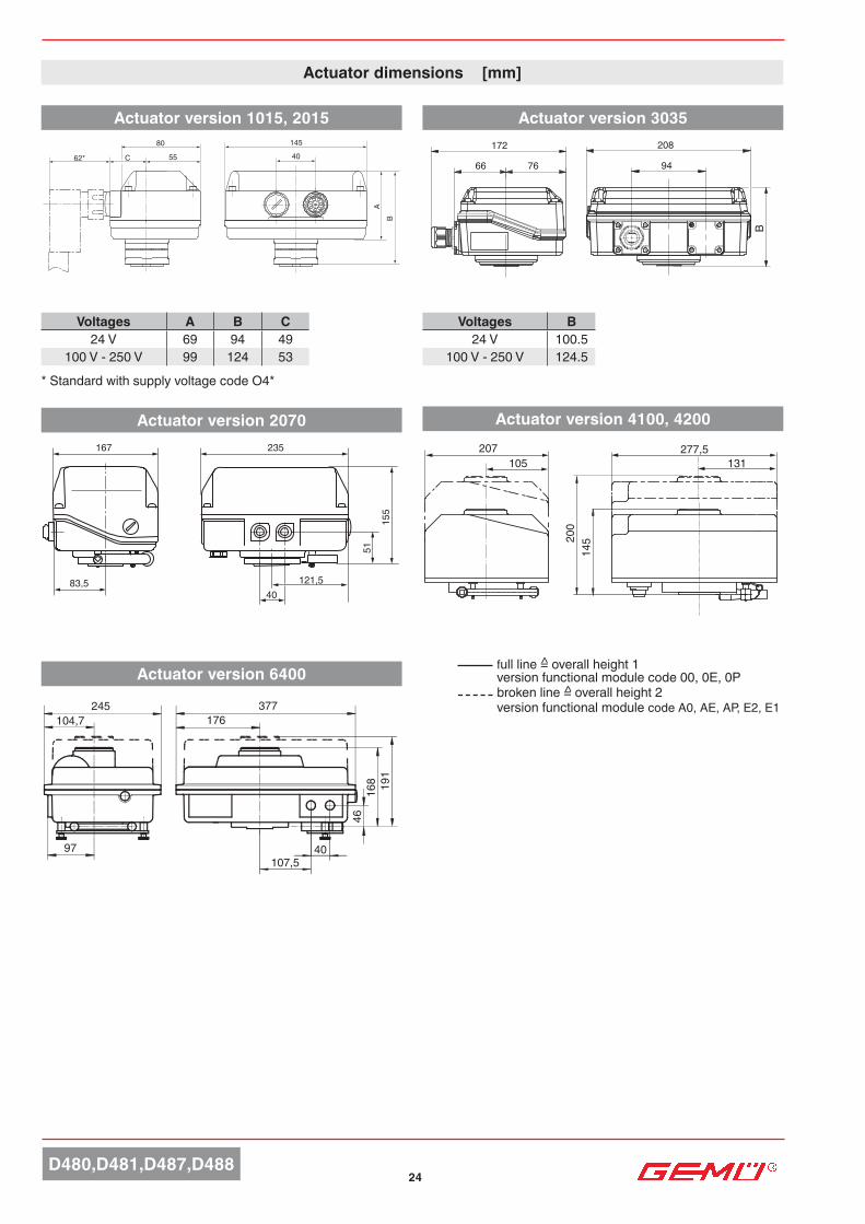
Actuator dimensions [mm]
Actuator version 2070
Voltages A B C24 V 69 94 49
100 V - 250 V 99 124 53
Actuator version 1015, 2015 Actuator version 3035
Voltages B24 V 100.5
100 V - 250 V 124.5
Actuator version 4100, 4200
Actuator version 6400
* Standard with supply voltage code O4*
full line = overall height 1 version functional module code 00, 0E, 0Pbroken line = overall height 2version functional module code A0, AE, AP, E2, E1
^
^

25D480,D481,D487,D488
14 Functional module CodeOPEN/CLOSE control with 2 additional potential-free limit switches AEOPEN/CLOSE control, with potentiometer output 5 kOhm APControl module; for external set value 4-20 mA E2Control module; for external set value 0-10 V DC E1Positioner DPS, 0 - 10 V, BSR accupack (NC) E11Positioner DPS 4 - 20 mA and BSR accupack (NC) E21With BSR accu pack - NC AE1With BSR accu pack - NO AE2
Min. / max. ambient temperature-20 to +70 °C
Special featureStandard manual override
Technical data - Motorized J+J actuators
Order data - GEMÜ D488 with motorized J+J actuators
Order example 1 2 3 4 5 6 7 8 9 10 13 14 15Code D488 U5 AE J4C55Order data butterfly valve (page 4, 5)
Technical data for liquids +20 to +80 °C
Correlation actuator version / nominal size
DNActuator version - Standard (code)
J4C20 20 Nm
J4C35 35 Nm
J4C55 55 Nm
J2140 140 Nm
J2300 300 Nm
25-50 X - - - -65-80 - X - - -100 - - X - -
125-150 - - - X -200-250 - - - - X
15 Actuator version CodeDN 25-50 (Torque 20 Nm) J4C20DN 65-80 (Torque 35 Nm) J4C35DN 100 (Torque 55 Nm) J4C55DN 125-150 (Torque 140 Nm) J2140DN 200-250 (Torque 300 Nm) J2300
Protection class to EN 60529IP 67 - J4C20, J4C35, J4C55IP 65 - J2140, J2300
Weight Actuator version J4C20 1.8 kgActuator version J4C35 1.9 kgActuator version J4C55 2.3 kgActuator version J2140 / J2300 5.2 kg
13 Voltage/frequency Code24 V AC/DC (-0/+5 %)Version 140, 300 C524 - 240 V AC/DC (-0/+0 %) Version 20, 35, 55, 85 U585 - 240 V AC/DC (-0/+5 %) Version 140, 300 S5
Power supplyRated voltageVersion J4C14/30 24 V AC/DC (0/+5 %) Version J4C20/35/55/85 24 - 240 V AC/DC (± 0%) All versions 85 - 240 V AC/DC (0/+ 5%)Rated frequency at AC rated voltage 50/60 Hz Rating 75 %
Operating times (± 10%)Actuator version
24- 240 V AC/DC Code U5
24 V, 85-240 V AC/DC Code C5, S5
J4C20 10 s -J4C35 10 s -J4C55 14 s -J4C85 30 s -J4C14 - 34 sJ4C30 - 58 s

POWER POS. E.L.S
128
(B) MAN(A) AUTO
107235
52452
214
126 51177
16/19
196
55 55
(B) MAN (A) AUTO
126 51177
16/19
196
55 55
(B) MAN (A) AUTO
VALVES, MEASUREMENTAND CONTROL SYSTEMS
GEMÜ Gebr. Müller · Apparatebau GmbH & Co. KG · Fritz-Müller-Str. 6-8 · D-74653 Ingelfingen-Criesbach · Tel. +49 (0) 7940/123-0 · Telefax +49 (0) 7940/[email protected] · www.gemu-group.com
Actuator dimensions [mm]
Actuator version - J2140 and J2300
For further butterfly valves, accessories and other products, please see our Product Range catalogue and Price List. Contact GEMÜ.
Actuator version - J4C20 / J4C35 Actuator version - J4C55
Subj
ect t
o al
tera
tion
· 03/
2020
· 88
3414
59Sh
ould
ther
e be
any
dou
bts o
r misu
nder
stan
ding
s, th
e G
erm
anve
rsio
n of
this
data
shee
t is th
e au
thor
itativ
e do
cum
ent!
All r
ight
s in
clud
ing
copy
right
and
indu
stria
l pr
oper
ty ri
ghts
are
exp
ress
ly re
serv
ed.