by f. zardi, e. filippi, a. scotto, f. laurenzi casale ... · carbon dioxide removal and ... the...
TRANSCRIPT
6900 Lugano Switzerland, Via G. Pocobelli 6 Tel +41.91.960.72.00 Fax +41.91.960.72.91/2 www.casale.ch [email protected]
Casale High Efficiency Design for Ammonia-
Urea Fertilizer Complex – A Perfect Blending of State-of-the-art
Technologies with Advanced Concepts
by F. Zardi, E. Filippi, A. Scotto, F. Laurenzi
Casale Group Lugano - Switzerland
presented at
FAI SEMINAR 2010 “Reforms in Fertiliser Sector”
New Delhi, India 29th November – 1st December 2010
2
Casale High Efficiency Design for Ammonia-Urea Fertilizer Complex – A Perfect Blending of State-of-the-art Technologies
with Advanced Concepts
by F. Zardi, E. Filippi, A. Scotto, F. Laurenzi
Casale Group Lugano - Switzerland
Abstract The founding company of the Casale Group, Ammonia Casale, has long been active in designing ammonia plants, mainly in the first half of the last century. Since the end of the 70’s, the Casale Group has gained a world-wide reputation for the revamping of existing ammonia and urea plants of any kind, gaining a leading position in this activity. In the last decade Casale has introduced advanced technologies for the design of grass-root/brown-field plants, according to which new plants have been built, or are under construction. These advancements are blend-in consolidated design concepts, obtaining significant gains in performances. The result is the Casale advanced process for the design of a combined and full integrated ammonia-urea fertilizer complex featuring very low energy consumption. This paper gives an overview of the Casale advanced ammonia-urea process, highlighting its most significant features and advantages. The paper presents also the applications of the described technologies, showing the role Casale can play being able to supply advanced designs for ammonia-urea grass-root/brown-field plants as single point of responsibility.
3
1. FOREWORD Ammonia Casale S.A. is one of the oldest companies active in the field of synthetic ammonia production, having been established in Lugano (Switzerland) in 1921 for the industrial development and commercialization of Dr Luigi Casale’s inventions for the catalytic synthesis of ammonia. Since the very beginning, and for many years now, Ammonia Casale has been active in the construction of new plants, with over 200 such plants built worldwide. More recently the activity of Ammonia Casale has been expanded also in the fields of urea and methanol production, and presently Casale is a group of companies active in various fields with its main focus on the development of technologies for the production of ammonia, urea and methanol. The main strength of Casale lies in the licensing of its technologies. Most of the technologies are developed in house by a team of very specialized and experienced people. Thanks to the innovative trend set by founder Dr Luigi Casale, plus the heritage and background of subsequent management teams, Casale invested significantly in technology. During the last decades this discipline evolved from an empirical art with an intuitive sense for good design into a more rationalized activity. Process design is now supported by sound insight into the chemistry of the processes, catalyst behaviors, kinetic data, heat and mass transfer phenomena, fluid mechanics, science of construction materials, and cost analysis. Casale Technical Services avail themselves of specialists in all the above fields, as well as of sophisticated tools for investigating, analyzing and picturing complex phenomena in a way unachievable with ordinary skilled manual calculations. The process design is based on advanced computer-aided techniques with applications ranging from process flow-sheeting to kinetics, to fluid dynamics simulations and mechanical stress analysis. Casale has been, in the last decades, very active in revamping existing plant and has extensive experience in the design and implementation of complete plant revamping projects, including major modifications to key equipment. Casale’s plant revamp strategy has always been to develop and apply new, advanced technologies to obtain the best possible improvement in plant performance at the minimum cost; with the aim of reducing the energy consumption and/or increasing the capacity. With the same strategy Casale has also developed, as a natural evolution of its revamping activity; new technologies for grass-roots ammonia and urea plants. This paper will present these technologies highlighting their features and some applications.
4
2. CASALE AMMONIA-UREA ADVANCED PROCESS The plant for the production of Urea is always downstream an ammonia plant, and an optimal integration of these two plants is essential to maximize the efficiency of the complex. CASALE being the only company owing both ammonia production and urea production technologies has concentrated his effort in obtaining the best overall economics. The ammonia and urea plants are designed to be best integrated, with optimized exchanges of energy and materials. In practice this translates in an overall consumption per ton of urea of only 4.6 Gcal/MT, including feed and fuel, electricity and utilities. This result has been obtained by integrating the steam balance of the two plants in such a way that there is no export of steam from the ammonia-urea complex and the import of electric power is 0.025 kW/MT urea. The steam consumption of urea plant is completely fulfilled by export of HP and MP (HP for the CO2 compressor and MP as process Steam) steam from ammonia plant, while there is no back export of LP steam from urea to ammonia. The CO2 production is balanced with ammonia production with a slight air excess in the secondary reformer and by burning as fuel a small amount of synthesis gas upstream the methanator. The necessary electric power is produced in two expanders in the ammonia plant. The high efficiency of the Casale Ammonia-Urea Advanced Process, which is shown also by the above performances and by the description in the next sections, makes it possible to reduce, for a given capacity, the size of the equipment and, therefore, to build a plant with lower investment costs than with other processes. Thanks to its features, the Casale Ammonia-Urea Advanced Process is also giving a very high reliability In the next two sections, the Casale processes for both the ammonia and the urea plants will be described.

5
Fig 1 – Casale Advanced Ammonia-Urea Process

6
3. CASALE ADVANCED PROCESS FOR GRASS-ROOTS AMMONIA PLANTS The Casale advanced ammonia process consists of the following sections: Feed gas desulphurization, Reforming, High and Low temperature shift conversion; Gas Turbine and Air compression; Carbon Dioxide removal and Methanation; Syngas compression; Ammonia synthesis and Condensation; Ammonia Refrigeration Section; Low temperature heat recovery (hereafter LTHR); Hydrogen Recovery Unit; Steam system.
Fig 2 – Casale Advanced Ammonia Process
7
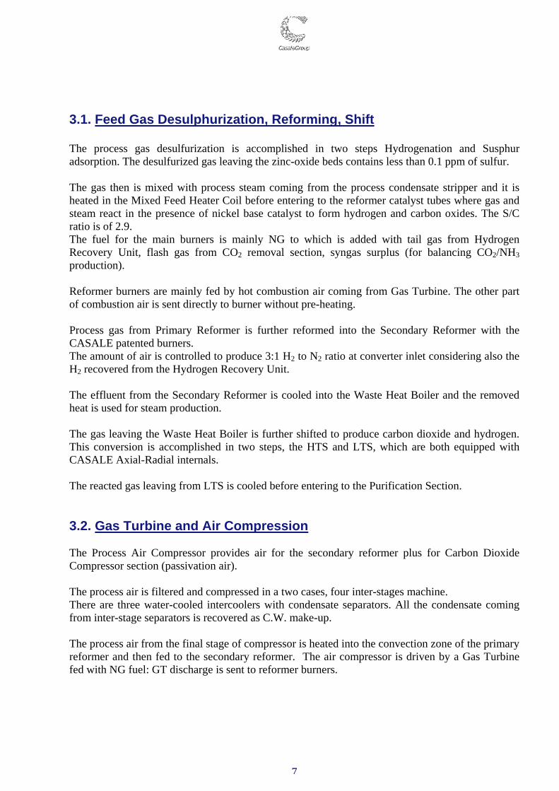
3.1. Feed Gas Desulphurization, Reforming, Shift The process gas desulfurization is accomplished in two steps Hydrogenation and Susphur adsorption. The desulfurized gas leaving the zinc-oxide beds contains less than 0.1 ppm of sulfur. The gas then is mixed with process steam coming from the process condensate stripper and it is heated in the Mixed Feed Heater Coil before entering to the reformer catalyst tubes where gas and steam react in the presence of nickel base catalyst to form hydrogen and carbon oxides. The S/C ratio is of 2.9. The fuel for the main burners is mainly NG to which is added with tail gas from Hydrogen Recovery Unit, flash gas from CO2 removal section, syngas surplus (for balancing CO2/NH3 production). Reformer burners are mainly fed by hot combustion air coming from Gas Turbine. The other part of combustion air is sent directly to burner without pre-heating. Process gas from Primary Reformer is further reformed into the Secondary Reformer with the CASALE patented burners. The amount of air is controlled to produce 3:1 H2 to N2 ratio at converter inlet considering also the H2 recovered from the Hydrogen Recovery Unit. The effluent from the Secondary Reformer is cooled into the Waste Heat Boiler and the removed heat is used for steam production. The gas leaving the Waste Heat Boiler is further shifted to produce carbon dioxide and hydrogen. This conversion is accomplished in two steps, the HTS and LTS, which are both equipped with CASALE Axial-Radial internals. The reacted gas leaving from LTS is cooled before entering to the Purification Section. 3.2. Gas Turbine and Air Compression The Process Air Compressor provides air for the secondary reformer plus for Carbon Dioxide Compressor section (passivation air). The process air is filtered and compressed in a two cases, four inter-stages machine. There are three water-cooled intercoolers with condensate separators. All the condensate coming from inter-stage separators is recovered as C.W. make-up. The process air from the final stage of compressor is heated into the convection zone of the primary reformer and then fed to the secondary reformer. The air compressor is driven by a Gas Turbine fed with NG fuel: GT discharge is sent to reformer burners.
8
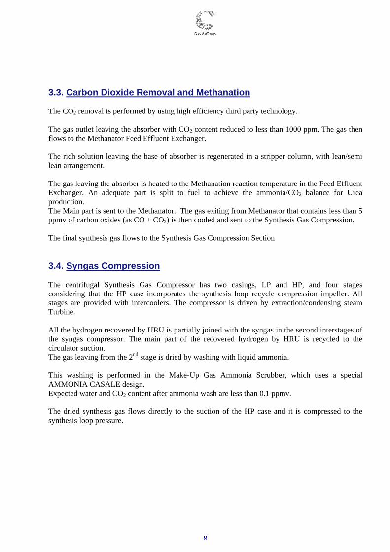
3.3. Carbon Dioxide Removal and Methanation The CO2 removal is performed by using high efficiency third party technology. The gas outlet leaving the absorber with CO2 content reduced to less than 1000 ppm. The gas then flows to the Methanator Feed Effluent Exchanger. The rich solution leaving the base of absorber is regenerated in a stripper column, with lean/semi lean arrangement. The gas leaving the absorber is heated to the Methanation reaction temperature in the Feed Effluent Exchanger. An adequate part is split to fuel to achieve the ammonia/CO2 balance for Urea production. The Main part is sent to the Methanator. The gas exiting from Methanator that contains less than 5 ppmv of carbon oxides (as CO + CO2) is then cooled and sent to the Synthesis Gas Compression. The final synthesis gas flows to the Synthesis Gas Compression Section 3.4. Syngas Compression The centrifugal Synthesis Gas Compressor has two casings, LP and HP, and four stages considering that the HP case incorporates the synthesis loop recycle compression impeller. All stages are provided with intercoolers. The compressor is driven by extraction/condensing steam Turbine. All the hydrogen recovered by HRU is partially joined with the syngas in the second interstages of the syngas compressor. The main part of the recovered hydrogen by HRU is recycled to the circulator suction. The gas leaving from the 2nd stage is dried by washing with liquid ammonia. This washing is performed in the Make-Up Gas Ammonia Scrubber, which uses a special AMMONIA CASALE design. Expected water and CO2 content after ammonia wash are less than 0.1 ppmv. The dried synthesis gas flows directly to the suction of the HP case and it is compressed to the synthesis loop pressure.

9
3.5. Ammonia Synthesis and Condensation The combined make-up and recycle gas stream from circulator is fed to the Hot Gas-Gas. The preheated gas then enters the ammonia converter, in which it reacts over an iron-based ammonia synthesis catalyst. Ammonia Converter is a typical well proven AMMONIA CASALE converter incorporate three adiabatic axial-radial beds, with intermediate cooling by heat exchange in two inter-bed exchangers. At the converter outlet, the product gas is cooled and the heat removed is used for steam production. The gas then passes through the hot side of the Hot Gas-Gas Exchangers and then enters in the condensation section where ammonia is condensed in the Water Cooler and in Ammonia Chillers. A considerable amount of ammonia is condensed in these coolers, due to the high ammonia concentration achieved with the high efficiency of the AMMONIA CASALE converter design.
3.6 Ammonia Refrigeration Section The ammonia refrigeration section mainly consists in a 4 stages compressor. Gaseous Ammonia of 4th stage discharge is condensed and collected in Refrigerant Receiver. The cold ammonia product is exported to the Urea plant by a pump: in normal operation, the cold ammonia pumped is send to heat recovery section inside the refrigeration section and then is delivered to Urea Plant at 20°C. When urea plant is down all the ammonia produced is delivered as cold ammonia at -33°C.
Fig. 3 – Casale Synthesis Converter
10
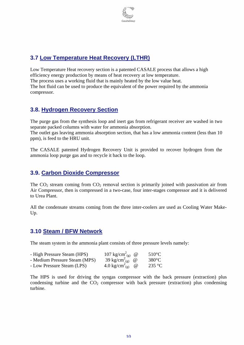
3.7 Low Temperature Heat Recovery (LTHR) Low Temperature Heat recovery section is a patented CASALE process that allows a high efficiency energy production by means of heat recovery at low temperature. The process uses a working fluid that is mainly heated by the low value heat. The hot fluid can be used to produce the equivalent of the power required by the ammonia compressor. 3.8. Hydrogen Recovery Section The purge gas from the synthesis loop and inert gas from refrigerant receiver are washed in two separate packed columns with water for ammonia absorption. The outlet gas leaving ammonia absorption section, that has a low ammonia content (less than 10 ppm), is feed to the HRU unit. The CASALE patented Hydrogen Recovery Unit is provided to recover hydrogen from the ammonia loop purge gas and to recycle it back to the loop. 3.9. Carbon Dioxide Compressor The CO2 stream coming from CO2 removal section is primarily joined with passivation air from Air Compressor, then is compressed in a two-case, four inter-stages compressor and it is delivered to Urea Plant. All the condensate streams coming from the three inter-coolers are used as Cooling Water Make-Up. 3.10 Steam / BFW Network The steam system in the ammonia plant consists of three pressure levels namely: - High Pressure Steam (HPS) 107 kg/cm2
(g) @ 510°C - Medium Pressure Steam (MPS) 39 kg/cm2
(g) @ 380°C - Low Pressure Steam (LPS) 4.0 kg/cm2
(g) @ 235 °C The HPS is used for driving the syngas compressor with the back pressure (extraction) plus condensing turbine and the CO2 compressor with back pressure (extraction) plus condensing turbine.
11
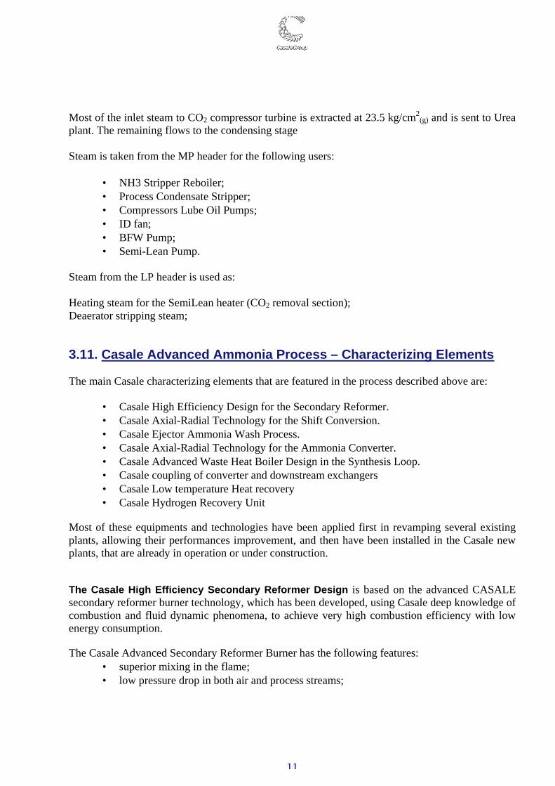
Most of the inlet steam to CO2 compressor turbine is extracted at 23.5 kg/cm2(g) and is sent to Urea
plant. The remaining flows to the condensing stage Steam is taken from the MP header for the following users:
• NH3 Stripper Reboiler; • Process Condensate Stripper; • Compressors Lube Oil Pumps; • ID fan; • BFW Pump; • Semi-Lean Pump.
Steam from the LP header is used as: Heating steam for the SemiLean heater (CO2 removal section); Deaerator stripping steam; 3.11. Casale Advanced Ammonia Process – Characterizing Elements The main Casale characterizing elements that are featured in the process described above are:
• Casale High Efficiency Design for the Secondary Reformer. • Casale Axial-Radial Technology for the Shift Conversion. • Casale Ejector Ammonia Wash Process. • Casale Axial-Radial Technology for the Ammonia Converter. • Casale Advanced Waste Heat Boiler Design in the Synthesis Loop. • Casale coupling of converter and downstream exchangers • Casale Low temperature Heat recovery • Casale Hydrogen Recovery Unit
Most of these equipments and technologies have been applied first in revamping several existing plants, allowing their performances improvement, and then have been installed in the Casale new plants, that are already in operation or under construction. The Casale High Efficiency Secondary Reformer Design is based on the advanced CASALE secondary reformer burner technology, which has been developed, using Casale deep knowledge of combustion and fluid dynamic phenomena, to achieve very high combustion efficiency with low energy consumption. The Casale Advanced Secondary Reformer Burner has the following features:
• superior mixing in the flame; • low pressure drop in both air and process streams;

12
• homogeneous gas composition and temperature distribution at catalyst bed entrance; • reduced flame length, avoiding catalyst impingement even at high operating loads; • low temperature of the burner surfaces exposed to the flames; • protection of the refractory lining from the hot core of the flame
Thanks to the above features of the burner, the Casale High Efficiency Secondary Reformer Design minimizes the size of this item, guaranteeing also a high reliability and efficiency, with a long duration of the burner itself. Casale designs not only the burner of this unit but also the vessel dimensions and shape, and specifies in details the refractory lining, the catalyst bed support and protection layer, thermocouples thermocouple position etc., ensuring a faultless construction of the complete unit. At present there are 11 Casale secondary reformers in operation, the first since 2002.
Both shift converters are designed according to the Casale Axial-Radial Technology, as well as the synthesis converter. The CASALE axial radial catalyst bed is proven since 1986 in more then 500 different units. Its main characteristics are:
• Best catalyst utilisation efficiency, 100 % of the catalyst volume is utilized for reaction
• Low pressure drop, guaranteed by the radial flow, that also allows the use of small size, more active, catalyst
• Highest conversion, thanks to 100 % efficiency of catalyst utilisation
• Simple mechanical construction, the bed consist only in a dished bottom and two vertical walls, no critical top cover, no manholes for bed access
Fig. 4 – Casale Secondary Reformer Burner
13
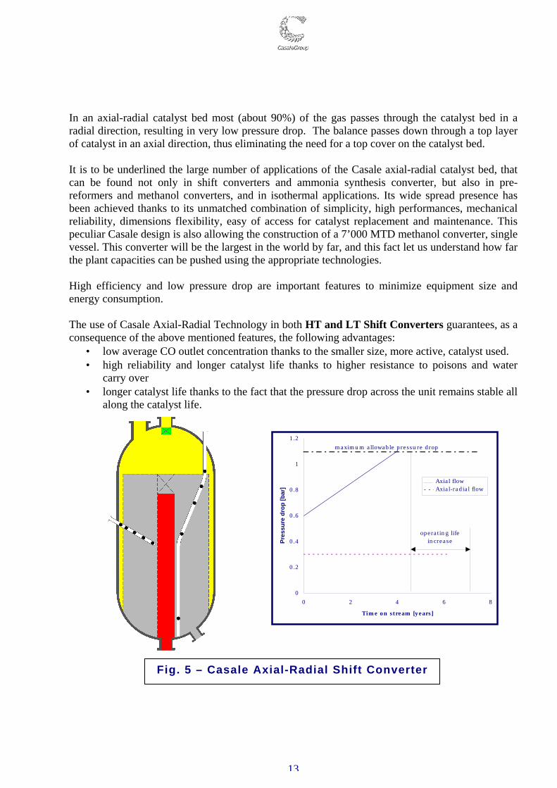
In an axial-radial catalyst bed most (about 90%) of the gas passes through the catalyst bed in a radial direction, resulting in very low pressure drop. The balance passes down through a top layer of catalyst in an axial direction, thus eliminating the need for a top cover on the catalyst bed. It is to be underlined the large number of applications of the Casale axial-radial catalyst bed, that can be found not only in shift converters and ammonia synthesis converter, but also in pre-reformers and methanol converters, and in isothermal applications. Its wide spread presence has been achieved thanks to its unmatched combination of simplicity, high performances, mechanical reliability, dimensions flexibility, easy of access for catalyst replacement and maintenance. This peculiar Casale design is also allowing the construction of a 7’000 MTD methanol converter, single vessel. This converter will be the largest in the world by far, and this fact let us understand how far the plant capacities can be pushed using the appropriate technologies. High efficiency and low pressure drop are important features to minimize equipment size and energy consumption. The use of Casale Axial-Radial Technology in both HT and LT Shift Converters guarantees, as a consequence of the above mentioned features, the following advantages:
• low average CO outlet concentration thanks to the smaller size, more active, catalyst used. • high reliability and longer catalyst life thanks to higher resistance to poisons and water
carry over • longer catalyst life thanks to the fact that the pressure drop across the unit remains stable all
along the catalyst life.
0
0.2
0.4
0.6
0.8
1
1.2
0 2 4 6 8
Time on stream [years]
Pres
sure
dro
p [b
ar]
operating lifeincrease
maximum allowable pressure drop
Axial flowAxial-radial flow
Fig. 5 – Casale Axial-Radial Shift Converter
14
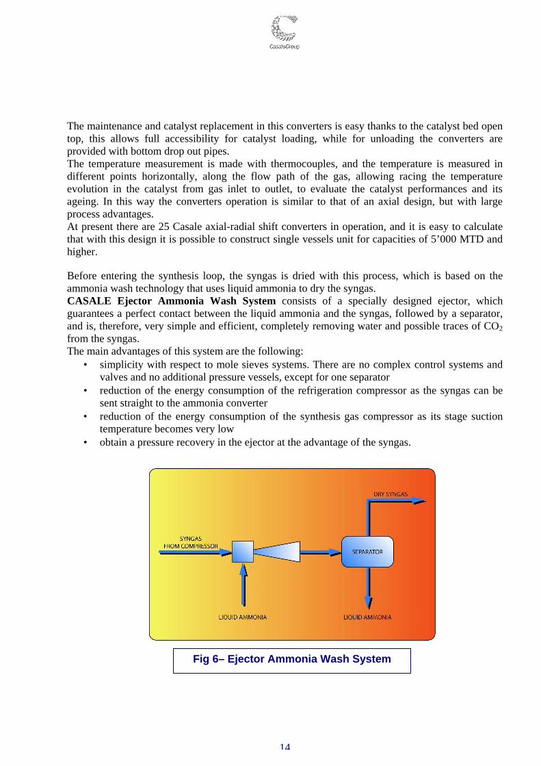
The maintenance and catalyst replacement in this converters is easy thanks to the catalyst bed open top, this allows full accessibility for catalyst loading, while for unloading the converters are provided with bottom drop out pipes. The temperature measurement is made with thermocouples, and the temperature is measured in different points horizontally, along the flow path of the gas, allowing racing the temperature evolution in the catalyst from gas inlet to outlet, to evaluate the catalyst performances and its ageing. In this way the converters operation is similar to that of an axial design, but with large process advantages. At present there are 25 Casale axial-radial shift converters in operation, and it is easy to calculate that with this design it is possible to construct single vessels unit for capacities of 5’000 MTD and higher. Before entering the synthesis loop, the syngas is dried with this process, which is based on the ammonia wash technology that uses liquid ammonia to dry the syngas. CASALE Ejector Ammonia Wash System consists of a specially designed ejector, which guarantees a perfect contact between the liquid ammonia and the syngas, followed by a separator, and is, therefore, very simple and efficient, completely removing water and possible traces of CO2 from the syngas. The main advantages of this system are the following:
• simplicity with respect to mole sieves systems. There are no complex control systems and valves and no additional pressure vessels, except for one separator
• reduction of the energy consumption of the refrigeration compressor as the syngas can be sent straight to the ammonia converter
• reduction of the energy consumption of the synthesis gas compressor as its stage suction temperature becomes very low
• obtain a pressure recovery in the ejector at the advantage of the syngas.
Fig 6– Ejector Ammonia Wash System

15
The ammonia synthesis converter is based on the Casale Axial-Radial Technology. This technology is applied in a three beds configuration with two interchangers, to reach a very high thermodynamic efficiency and catalyst volume utilization. The conversion per pass is, therefore, very high, exceeding 20 % vol concentration of NH3 at converter exit, minimizing the circulation rate, the energy consumption of the loop and the size of the loop equipment. The Casale converter is very well known, being already in service in more then 160 plants worldwide, with capacities ranging from 100 MTD to 2’200 MTD. The Casale converter design has also an impressive reliability record, has there are cases of more then 20 years of operation without opening. The Casale converter is designed with a vessel flushed with cool inlet gas, eliminating the problem of vessel cracking due to the well known combined effect of hydrogen embrittlement and nitrading. In addition to its high performances and proven reliability this converter offers a simplified maintenance and catalyst replacement, thanks to the open top catalyst beds, that offers the full cross section for accessing the catalyst during its replacement, and the easy removability of the beds and interchangers, thanks to the peculiar Casale supporting systems of the baskets, that are just sitting on a ring, part of the cartridge wall, (Fig. 8). In this way, the baskets can be introduced in the cartridge or lifted off without bolting, welding or cutting, and without the need to even access the supports. This system is complemented by the use of elastic ring sliding joints for all internal nozzle connections. These joints are the most reliable, being free of any weak components like bolts, gaskets or packing rope, and allow to decouple the interchangers without any mechanical operation like unbolting, cutting, etc. The Casale converter is best coupled with the Casale Advanced Design for the loop waste heat boiler, downstream the converter for heat recovery by steam generation. The Casale Waste Heat Boiler is a U tubes exchanger with the boiling water on the tube side and the process gas shell side. The pressure shell is kept cool by the colder synthesis gas, exiting the unit, that is flowing in an annulus along the shell. The only ferritic parts in contact with the hot gas are the tubes, which are cooled by the boiling water. With this special design it is possible to avoid any risk of nitrading.
Fig 7 – Casale Sliding Joint
Fig 8 – Casale Bed Support
16
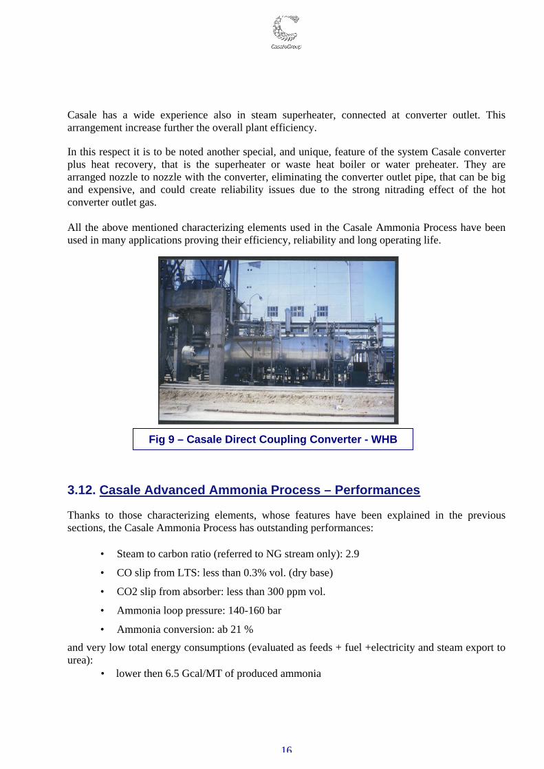
Casale has a wide experience also in steam superheater, connected at converter outlet. This arrangement increase further the overall plant efficiency. In this respect it is to be noted another special, and unique, feature of the system Casale converter plus heat recovery, that is the superheater or waste heat boiler or water preheater. They are arranged nozzle to nozzle with the converter, eliminating the converter outlet pipe, that can be big and expensive, and could create reliability issues due to the strong nitrading effect of the hot converter outlet gas. All the above mentioned characterizing elements used in the Casale Ammonia Process have been used in many applications proving their efficiency, reliability and long operating life. 3.12. Casale Advanced Ammonia Process – Performances Thanks to those characterizing elements, whose features have been explained in the previous sections, the Casale Ammonia Process has outstanding performances:
• Steam to carbon ratio (referred to NG stream only): 2.9
• CO slip from LTS: less than 0.3% vol. (dry base)
• CO2 slip from absorber: less than 300 ppm vol.
• Ammonia loop pressure: 140-160 bar
• Ammonia conversion: ab 21 %
and very low total energy consumptions (evaluated as feeds + fuel +electricity and steam export to urea):
• lower then 6.5 Gcal/MT of produced ammonia
Fig 9 – Casale Direct Coupling Converter - WHB
17
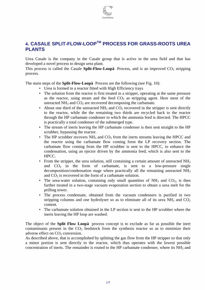
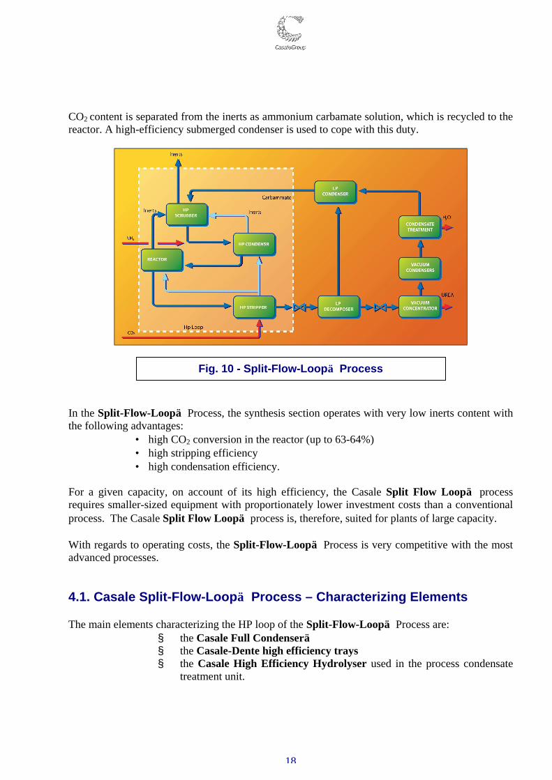
4. CASALE SPLIT-FLOW-LOOPTM PROCESS FOR GRASS-ROOTS UREA PLANTS Urea Casale is the company in the Casale group that is active in the urea field and that has developed a novel process to design urea plant. This process is called the Casale Split-Flow-Loop Process, and is an improved CO2 stripping process. The main steps of the Split-Flow-Loop Process are the following (see Fig. 10):
• Urea is formed in a reactor fitted with High Efficiency trays • The solution from the reactor is first treated in a stripper, operating at the same pressure
as the reactor, using steam and the feed CO2 as stripping agent. Here most of the unreacted NH3 and CO2 are recovered decomposing the carbamate.
• About one third of the unreacted NH3 and CO2 recovered in the stripper is sent directly to the reactor, while the the remaining two thirds are recycled back to the reactor through the HP carbamate condenser to which the ammonia feed is directed. The HPCC is practically a total condenser of the submerged type.
• The stream of inerts leaving the HP carbamate condenser is then sent straight to the HP scrubber, bypassing the reactor.
• The HP scrubber recovers NH3 and CO2 from the inerts streams leaving the HPCC and the reactor using the carbamate flow coming form the LP recovery section. The carbamate flow coming from the HP scrubber is sent to the HPCC, to enhance the condensation, using an ejector driven by the ammonia feed, which is also sent to the HPCC.
• From the stripper, the urea solution, still containing a certain amount of unreacted NH3 and CO2 in the form of carbamate, is sent to a low-pressure single decomposition/condensation stage where practically all the remaining unreacted NH3 and CO2 is recovered in the form of a carbamate solution.
• The urea-water solution, containing only small quantities of NH3 and CO2, is then further treated in a two-stage vacuum evaporation section to obtain a urea melt for the prilling tower.
• The process condensate, obtained from the vacuum condensers is purified in two stripping columns and one hydrolyser so as to eliminate all of its urea NH3 and CO2 content.
• The carbamate solution obtained in the LP section is sent to the HP scrubber where the inerts leaving the HP loop are washed.
The object of the Split Flow Loop process concept is to exclude as far as possible the inert contaminants present in the CO2 feedstock from the synthesis reactor so as to minimize their adverse effect on CO2 conversion. As described above, that is accomplished by splitting the gas flow from the HP stripper so that only a minor portion is sent directly to the reactor, which thus operates with the lowest possible concentration of inerts. The remainder is routed to the HP carbamate condenser, where its NH3 and
18
CO2 content is separated from the inerts as ammonium carbamate solution, which is recycled to the reactor. A high-efficiency submerged condenser is used to cope with this duty.
In the Split-Flow-Loop Process, the synthesis section operates with very low inerts content with the following advantages:
• high CO2 conversion in the reactor (up to 63-64%) • high stripping efficiency • high condensation efficiency.
For a given capacity, on account of its high efficiency, the Casale Split Flow Loop process requires smaller-sized equipment with proportionately lower investment costs than a conventional process. The Casale Split Flow Loop process is, therefore, suited for plants of large capacity. With regards to operating costs, the Split-Flow-Loop Process is very competitive with the most advanced processes. 4.1. Casale Split-Flow-Loop Process – Characterizing Elements The main elements characterizing the HP loop of the Split-Flow-Loop Process are:
§ the Casale Full Condenser § the Casale-Dente high efficiency trays § the Casale High Efficiency Hydrolyser used in the process condensate
treatment unit.
Fig. 10 - Split-Flow-Loop Process
19
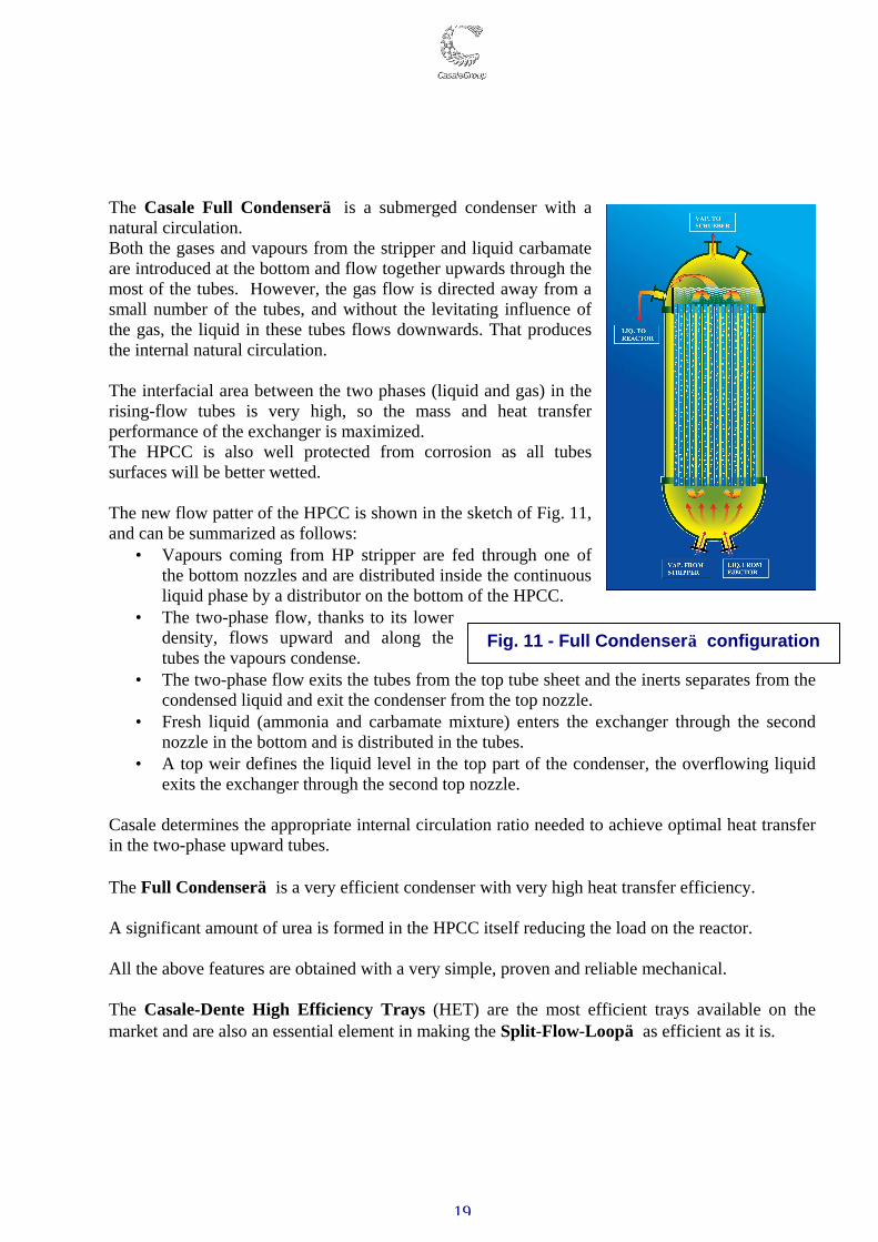
The Casale Full Condenser is a submerged condenser with a natural circulation. Both the gases and vapours from the stripper and liquid carbamate are introduced at the bottom and flow together upwards through the most of the tubes. However, the gas flow is directed away from a small number of the tubes, and without the levitating influence of the gas, the liquid in these tubes flows downwards. That produces the internal natural circulation. The interfacial area between the two phases (liquid and gas) in the rising-flow tubes is very high, so the mass and heat transfer performance of the exchanger is maximized. The HPCC is also well protected from corrosion as all tubes surfaces will be better wetted. The new flow patter of the HPCC is shown in the sketch of Fig. 11, and can be summarized as follows:
• Vapours coming from HP stripper are fed through one of the bottom nozzles and are distributed inside the continuous liquid phase by a distributor on the bottom of the HPCC.
• The two-phase flow, thanks to its lower density, flows upward and along the tubes the vapours condense.
• The two-phase flow exits the tubes from the top tube sheet and the inerts separates from the condensed liquid and exit the condenser from the top nozzle.
• Fresh liquid (ammonia and carbamate mixture) enters the exchanger through the second nozzle in the bottom and is distributed in the tubes.
• A top weir defines the liquid level in the top part of the condenser, the overflowing liquid exits the exchanger through the second top nozzle.
Casale determines the appropriate internal circulation ratio needed to achieve optimal heat transfer in the two-phase upward tubes. The Full Condenser is a very efficient condenser with very high heat transfer efficiency. A significant amount of urea is formed in the HPCC itself reducing the load on the reactor. All the above features are obtained with a very simple, proven and reliable mechanical. The Casale-Dente High Efficiency Trays (HET) are the most efficient trays available on the market and are also an essential element in making the Split-Flow-Loop as efficient as it is.
Fig. 11 - Full Condenser configuration
20
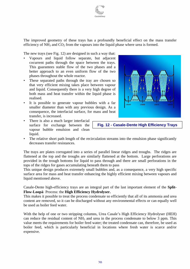
The improved geometry of these trays has a profoundly beneficial effect on the mass transfer efficiency of NH3 and CO2 from the vapours into the liquid phase where urea is formed. The new trays (see Fig. 12) are designed in such a way that: • Vapours and liquid follow separate, but adjacent
cocurrent paths through the space between the trays. This guarantees stable flow of the two phases and a better approach to an even uniform flow of the two phases throughout the whole reactor.
• These separated paths through the tray are chosen so that very efficient mixing takes place between vapour and liquid. Consequently there is a very high degree of both mass and heat transfer within the liquid phase is realised.
• It is possible to generate vapour bubbles with a far smaller diameter than with any previous design. As a consequence, the interfacial surface, for mass and heat transfer, is increased.
• There is also a much larger interfacial surface for exchange between the vapour bubble emulsion and clean liquid.
• The relative short path length of the recirculation streams into the emulsion phase significantly decreases transfer resistances.
The trays are plates corrugated into a series of parallel linear ridges and troughs. The ridges are flattened at the top and the troughs are similarly flattened at the bottom. Large perforations are provided in the trough bottoms for liquid to pass through and there are small perforations in the tops of the ridges for gases accumulating beneath them to pass This unique design produces extremely small bubbles and, as a consequence, a very high specific surface area for mass and heat transfer enhancing the highly efficient mixing between vapours and liquid mentioned above. Casale-Dente high-efficiency trays are an integral part of the last important element of the Split-Flow-Loop Process: the High Efficiency Hydrolyser. This makes it possible to treat the process condensate so efficiently that all of its ammonia and urea content are removed, so it can be discharged without any environmental effects or can equally well be used as boiler feed water. With the help of one or two stripping columns, Urea Casale’s High Efficiency Hydrolyser (HEH) can reduce the residual content of NH3 and urea in the process condensate to below 3 ppm. This value meets the requirements for boiler feed water; the treated condensate can, therefore, be used as boiler feed, which is particularly beneficial in locations where fresh water is scarce and/or expensive.
Fig. 12 - Casale-Dente High Efficiency Trays
21
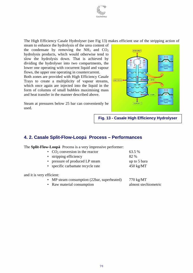
The High Efficiency Casale Hydrolyser (see Fig 13) makes efficient use of the stripping action of steam to enhance the hydrolysis of the urea content of the condensate by removing the NH3 and CO2 hydrolysis products, which would otherwise tend to slow the hydrolysis down. That is achieved by dividing the hydrolyser into two compartments, the lower one operating with cocurrent liquid and vapour flows, the upper one operating in countercurrent. Both zones are provided with High Efficiency Casale Trays to create a multiplicity of vapour streams, which once again are injected into the liquid in the form of columns of small bubbles maximising mass and heat transfer in the manner described above. Steam at pressures below 25 bar can conveniently be used. 4. 2. Casale Split-Flow-Loop Process – Performances The Split-Flow-Loop Process is a very impressive performer:
• CO2 conversion in the reactor 63.5 % • stripping efficiency 82 % • pressure of produced LP steam up to 5 bara • specific carbamate recycle rate 450 kg/MT
and it is very efficient:
• MP steam consumption (22bar, superheated) 770 kg/MT • Raw material consumption almost stechiometric
Fig. 13 - Casale High Efficiency Hydrolyser

22
5. CASALE AMMONIA-UREA PROCESS – ENVIRONMENTAL IMPACT The CASALE Ammonia-Urea Process has been designed in such a way as to minimize the environmental impact. In fact, the only liquid wastes are the boiler blow down, the air compressor interstage coolers condensate and the urea process condensate. The boiler blow down, after flashing and cooling, is used as cooling water make-up for the cooling water loop. The same for the air compressor interstage condensate, which is returned to the cooling water return header. The process condensate from the urea plant is, as described above returned clean as boiler feed water. The only gaseous wastes are the flue gas from the primary reformer, the inerts from the urea plant and the air exhaust from the prilling tower. The flue gas from the primary reformer contains about 110 mg/Nm3 of NOx. The guaranteed figure of NOx is less than the one required by the European Community for new plants (140 mg/NM3 calculated at 3% oxygen excess). The ammonia content in the other gaseous waste can be kept below the allowable emission levels.
23
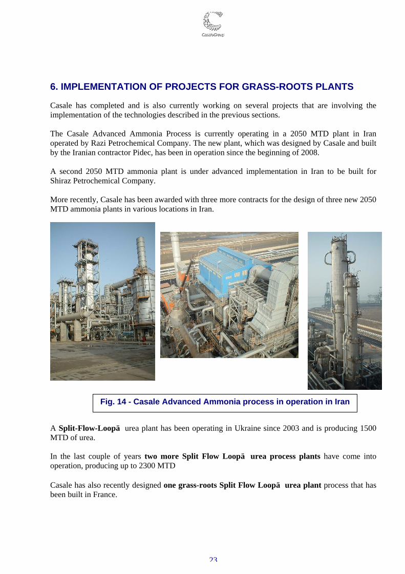
6. IMPLEMENTATION OF PROJECTS FOR GRASS-ROOTS PLANTS Casale has completed and is also currently working on several projects that are involving the implementation of the technologies described in the previous sections. The Casale Advanced Ammonia Process is currently operating in a 2050 MTD plant in Iran operated by Razi Petrochemical Company. The new plant, which was designed by Casale and built by the Iranian contractor Pidec, has been in operation since the beginning of 2008. A second 2050 MTD ammonia plant is under advanced implementation in Iran to be built for Shiraz Petrochemical Company. More recently, Casale has been awarded with three more contracts for the design of three new 2050 MTD ammonia plants in various locations in Iran.
A Split-Flow-Loop urea plant has been operating in Ukraine since 2003 and is producing 1500 MTD of urea. In the last couple of years two more Split Flow Loop urea process plants have come into operation, producing up to 2300 MTD Casale has also recently designed one grass-roots Split Flow Loop urea plant process that has been built in France.
Fig. 14 - Casale Advanced Ammonia process in operation in Iran
24
7. CONCLUSIONS Through the continuous development of its technologies, Casale has been able to develop innovative processes for world-scale ammonia and urea grass-roots plants. With these new processes Casale can design world scale fertilizer plants and is ready to respond to the future market demand for plant capacity with its advanced processes specially conceived for plants of very large capacity. Casale is now in the unique position of owning proprietary technologies for the design of ammonia-urea grass-roots plants. Lugano, October 2010