by mohammadsadegh faraji - tspace repository: … · mohammadsadegh faraji master of science ......
TRANSCRIPT

Identity and Access Management in Multi-tier Cloud Infrastructure
by
MohammadSadegh Faraji
A thesis submitted in conformity with the requirementsfor the degree of Master of Science
Graduate Department of Electrical and Computer EngineeringUniversity of Toronto
c© Copyright 2013 by MohammadSadegh Faraji
Abstract
Identity and Access Management in Multi-tier Cloud Infrastructure
MohammadSadegh Faraji
Master of Science
Graduate Department of Electrical and Computer Engineering
University of Toronto
2013
The SAVI IAM is an identity and access management system for the Multi-tier cloud infrastructure. The
goal of the SAVI IAM is to provide a flexible system to enable applications to adopt the cloud rapidly
rather than concentrating on a specific function such as federation. The SAVI IAM distinguishes itself
from previous work in three aspects: comprehensiveness, stability, and technology independence.The
SAVI IAM is a comprehensive solution for cloud providers. It uses two fine-grained access control
model: constrained Role-based Access Control and Attribute-based access control. To address appli-
cation requirement, it has implemented delegation and trust mechanism to enable administrators to
delegate their authorities temporarily to applications.
The SAVI IAM is scalable in the sense than it can address huge number of requests by increasing
the number of instances. On the other hand, the middleware component is able to cache local data in
order to boost the performance of the the infrastructure. The SAVI IAM is built on top of Openstack
Keystone v2.0, and supports Openstack, Amazon EC2, and SAVI APIs.
ii

Dedication
I dedicate my thesis work to my family. A special feeling of gratitude to my loving parents whose words
of encouragement and push for tenacity ring in my ears.
iii

Contents
1 Introduction 1
Introduction 1
1.1 Identity and Access Management in Multi-tier Cloud . . . . . . . . . . . . . . . . . . . . . 1
1.2 Motivation . . . . . . . . . . . . . . . . . . . . . . . . . . . . . . . . . . . . . . . . . . . . 3
1.3 Research Questions . . . . . . . . . . . . . . . . . . . . . . . . . . . . . . . . . . . . . . . . 3
1.3.1 Challenges . . . . . . . . . . . . . . . . . . . . . . . . . . . . . . . . . . . . . . . . 4
1.3.2 Research Barriers . . . . . . . . . . . . . . . . . . . . . . . . . . . . . . . . . . . . . 4
1.3.3 Scope of Research . . . . . . . . . . . . . . . . . . . . . . . . . . . . . . . . . . . . 4
1.4 Methodology . . . . . . . . . . . . . . . . . . . . . . . . . . . . . . . . . . . . . . . . . . . 5
1.4.1 Development Phases . . . . . . . . . . . . . . . . . . . . . . . . . . . . . . . . . . . 5
1.5 Organization of thesis . . . . . . . . . . . . . . . . . . . . . . . . . . . . . . . . . . . . . . 6
1.6 Contribution . . . . . . . . . . . . . . . . . . . . . . . . . . . . . . . . . . . . . . . . . . . 8
2 Background and Related works 9
Background and Related works 9
2.1 Cloud Computing . . . . . . . . . . . . . . . . . . . . . . . . . . . . . . . . . . . . . . . . . 9
2.1.1 Cloud Characteristics . . . . . . . . . . . . . . . . . . . . . . . . . . . . . . . . . . 9
2.1.2 Cloud Service Model . . . . . . . . . . . . . . . . . . . . . . . . . . . . . . . . . . . 10
2.1.3 Deployment Model . . . . . . . . . . . . . . . . . . . . . . . . . . . . . . . . . . . . 11
2.2 Cloud Security . . . . . . . . . . . . . . . . . . . . . . . . . . . . . . . . . . . . . . . . . . 12
2.2.1 Identity and Access Management . . . . . . . . . . . . . . . . . . . . . . . . . . . . 14
2.2.2 Traditional Identity Management Model . . . . . . . . . . . . . . . . . . . . . . . . 16
2.2.3 Cloud Computing Identity Management Models . . . . . . . . . . . . . . . . . . . 17
2.3 Multi-tier Cloud . . . . . . . . . . . . . . . . . . . . . . . . . . . . . . . . . . . . . . . . . 20
2.3.1 Smart Application on Virtual Infrastructure (SAVI) . . . . . . . . . . . . . . . . . 21
2.3.2 The Global Environment for Network Innovations (GENI) . . . . . . . . . . . . . . 25
2.3.3 Conclusion . . . . . . . . . . . . . . . . . . . . . . . . . . . . . . . . . . . . . . . . 28
3 Threat Modelling 29
Threat Modelling 29
3.1 Introduction . . . . . . . . . . . . . . . . . . . . . . . . . . . . . . . . . . . . . . . . . . . . 29
3.2 Threat Modelling Techniques . . . . . . . . . . . . . . . . . . . . . . . . . . . . . . . . . . 30
iv

3.3 Threat Modelling . . . . . . . . . . . . . . . . . . . . . . . . . . . . . . . . . . . . . . . . . 31
3.3.1 SAVI Characterization . . . . . . . . . . . . . . . . . . . . . . . . . . . . . . . . . 32
3.3.2 SAVI Asset . . . . . . . . . . . . . . . . . . . . . . . . . . . . . . . . . . . . . . . . 33
3.3.3 SAVI Threats . . . . . . . . . . . . . . . . . . . . . . . . . . . . . . . . . . . . . . . 33
3.3.4 Attack-Asset-Entry Relationship . . . . . . . . . . . . . . . . . . . . . . . . . . . . 36
3.4 Conclusion . . . . . . . . . . . . . . . . . . . . . . . . . . . . . . . . . . . . . . . . . . . . 36
4 SAVI IAM 38
SAVI IAM 38
4.1 Introduction . . . . . . . . . . . . . . . . . . . . . . . . . . . . . . . . . . . . . . . . . . . . 38
4.2 SAVI Security Architecture . . . . . . . . . . . . . . . . . . . . . . . . . . . . . . . . . . . 40
4.2.1 AAA . . . . . . . . . . . . . . . . . . . . . . . . . . . . . . . . . . . . . . . . . . . . 41
4.2.2 Configuration . . . . . . . . . . . . . . . . . . . . . . . . . . . . . . . . . . . . . . . 42
4.2.3 Registry . . . . . . . . . . . . . . . . . . . . . . . . . . . . . . . . . . . . . . . . . . 42
4.2.4 Incident Handling . . . . . . . . . . . . . . . . . . . . . . . . . . . . . . . . . . . . 42
4.3 Identity and Access Management . . . . . . . . . . . . . . . . . . . . . . . . . . . . . . . . 43
4.3.1 Requirements Analysis . . . . . . . . . . . . . . . . . . . . . . . . . . . . . . . . . . 43
4.3.2 Proposed System Design . . . . . . . . . . . . . . . . . . . . . . . . . . . . . . . . . 45
4.3.3 Identity Manager . . . . . . . . . . . . . . . . . . . . . . . . . . . . . . . . . . . . . 47
4.3.4 Policy Management . . . . . . . . . . . . . . . . . . . . . . . . . . . . . . . . . . . 48
4.3.5 Token Management . . . . . . . . . . . . . . . . . . . . . . . . . . . . . . . . . . . 48
4.3.6 Authentication Component . . . . . . . . . . . . . . . . . . . . . . . . . . . . . . . 49
4.3.7 Middleware . . . . . . . . . . . . . . . . . . . . . . . . . . . . . . . . . . . . . . . . 50
4.4 Implementation . . . . . . . . . . . . . . . . . . . . . . . . . . . . . . . . . . . . . . . . . . 51
4.5 Conclusion . . . . . . . . . . . . . . . . . . . . . . . . . . . . . . . . . . . . . . . . . . . . 55
5 Access Control 56
Access Control 56
5.1 Introduction . . . . . . . . . . . . . . . . . . . . . . . . . . . . . . . . . . . . . . . . . . . . 56
5.2 Background . . . . . . . . . . . . . . . . . . . . . . . . . . . . . . . . . . . . . . . . . . . . 57
5.3 Requirement Analysis . . . . . . . . . . . . . . . . . . . . . . . . . . . . . . . . . . . . . . 58
5.4 The Proposed Design . . . . . . . . . . . . . . . . . . . . . . . . . . . . . . . . . . . . . . . 59
5.4.1 Role-Based Access Control . . . . . . . . . . . . . . . . . . . . . . . . . . . . . . . 60
5.4.2 Attribute-Based Access Control . . . . . . . . . . . . . . . . . . . . . . . . . . . . . 61
5.4.3 Delegation and Trust . . . . . . . . . . . . . . . . . . . . . . . . . . . . . . . . . . . 64
5.5 Conclusion . . . . . . . . . . . . . . . . . . . . . . . . . . . . . . . . . . . . . . . . . . . . 65
6 Performance and Scalability 66
Performance and Scalability 66
6.1 Introduction . . . . . . . . . . . . . . . . . . . . . . . . . . . . . . . . . . . . . . . . . . . . 66
6.2 Requirement Analysis . . . . . . . . . . . . . . . . . . . . . . . . . . . . . . . . . . . . . . 66
6.2.1 Scalability Issues . . . . . . . . . . . . . . . . . . . . . . . . . . . . . . . . . . . . . 67
v
6.2.2 Scalability Strategies . . . . . . . . . . . . . . . . . . . . . . . . . . . . . . . . . . . 68
6.3 Proposed Design . . . . . . . . . . . . . . . . . . . . . . . . . . . . . . . . . . . . . . . . . 69
6.3.1 Caching Layer . . . . . . . . . . . . . . . . . . . . . . . . . . . . . . . . . . . . . . 70
6.3.2 Middleware . . . . . . . . . . . . . . . . . . . . . . . . . . . . . . . . . . . . . . . . 72
6.3.3 Load balancing . . . . . . . . . . . . . . . . . . . . . . . . . . . . . . . . . . . . . . 73
6.4 Performance Evaluation . . . . . . . . . . . . . . . . . . . . . . . . . . . . . . . . . . . . . 73
6.4.1 Apache JMeter . . . . . . . . . . . . . . . . . . . . . . . . . . . . . . . . . . . . . . 74
6.4.2 SAVI IAM Setup . . . . . . . . . . . . . . . . . . . . . . . . . . . . . . . . . . . . . 75
6.4.3 Test Scenarios . . . . . . . . . . . . . . . . . . . . . . . . . . . . . . . . . . . . . . 77
6.5 Conclusion . . . . . . . . . . . . . . . . . . . . . . . . . . . . . . . . . . . . . . . . . . . . 80
7 Conclusion and Future scope 82
Conclusion and Future scope 82
7.1 Future work . . . . . . . . . . . . . . . . . . . . . . . . . . . . . . . . . . . . . . . . . . . . 82
7.2 Conclusion . . . . . . . . . . . . . . . . . . . . . . . . . . . . . . . . . . . . . . . . . . . . 82
Bibliography 84
vi

List of Tables
3.1 Attack Asset Relationship . . . . . . . . . . . . . . . . . . . . . . . . . . . . . . . . . . . . 36
4.1 SAVI Resources . . . . . . . . . . . . . . . . . . . . . . . . . . . . . . . . . . . . . . . . . . 47
6.1 SAVI IAM functions traffic . . . . . . . . . . . . . . . . . . . . . . . . . . . . . . . . . . . 69
6.2 SAVI IAM System Characteristics . . . . . . . . . . . . . . . . . . . . . . . . . . . . . . . 74
vii
List of Figures
1.1 Multi-tier cloud infrastructure . . . . . . . . . . . . . . . . . . . . . . . . . . . . . . . . . . 2
1.2 Research Structure . . . . . . . . . . . . . . . . . . . . . . . . . . . . . . . . . . . . . . . . 7
2.1 Cloud service model and deployment model . . . . . . . . . . . . . . . . . . . . . . . . . . 12
2.2 Identity Lifecycle Management [21] . . . . . . . . . . . . . . . . . . . . . . . . . . . . . . . 15
2.3 Multi-tier architecture . . . . . . . . . . . . . . . . . . . . . . . . . . . . . . . . . . . . . . 21
2.4 SAVI architecture . . . . . . . . . . . . . . . . . . . . . . . . . . . . . . . . . . . . . . . . . 22
2.5 SAVI Logical Structure . . . . . . . . . . . . . . . . . . . . . . . . . . . . . . . . . . . . . 23
2.6 SAVI component diagram . . . . . . . . . . . . . . . . . . . . . . . . . . . . . . . . . . . . 24
2.7 GENI Architecture . . . . . . . . . . . . . . . . . . . . . . . . . . . . . . . . . . . . . . . . 26
2.8 Conceptual View of ExoGENI software stack . . . . . . . . . . . . . . . . . . . . . . . . . 27
3.1 Operation ”Aurora” Hit Google (Mid. 2009 Dec. 2009) [68] . . . . . . . . . . . . . . . . 31
3.2 SAVI Trust Level . . . . . . . . . . . . . . . . . . . . . . . . . . . . . . . . . . . . . . . . . 32
4.1 SAVI Testbed Main Entities and IAM . . . . . . . . . . . . . . . . . . . . . . . . . . . . . 40
4.2 SAVI TB Clearinghouse internal components . . . . . . . . . . . . . . . . . . . . . . . . . 41
4.3 IAM Architecture . . . . . . . . . . . . . . . . . . . . . . . . . . . . . . . . . . . . . . . . . 46
4.4 Manifesting Management UML Diagram . . . . . . . . . . . . . . . . . . . . . . . . . . . . 47
4.5 Identity Management UML Diagram . . . . . . . . . . . . . . . . . . . . . . . . . . . . . . 48
4.6 An Authentication Request . . . . . . . . . . . . . . . . . . . . . . . . . . . . . . . . . . . 50
4.7 IAM Middleware Architecture . . . . . . . . . . . . . . . . . . . . . . . . . . . . . . . . . . 50
4.8 Openstack Keystone v2.0 Essex Architecture . . . . . . . . . . . . . . . . . . . . . . . . . 51
4.9 SAVI portal homepage . . . . . . . . . . . . . . . . . . . . . . . . . . . . . . . . . . . . . . 52
4.10 Project Management Page . . . . . . . . . . . . . . . . . . . . . . . . . . . . . . . . . . . . 53
4.11 Join Project Page . . . . . . . . . . . . . . . . . . . . . . . . . . . . . . . . . . . . . . . . . 53
4.12 Switch between projects . . . . . . . . . . . . . . . . . . . . . . . . . . . . . . . . . . . . . 54
4.13 Switch between regions . . . . . . . . . . . . . . . . . . . . . . . . . . . . . . . . . . . . . . 54
5.1 SAVI Authorization Architecture . . . . . . . . . . . . . . . . . . . . . . . . . . . . . . . . 60
5.2 Core RBAC Model . . . . . . . . . . . . . . . . . . . . . . . . . . . . . . . . . . . . . . . . 61
6.1 Single Process IAM . . . . . . . . . . . . . . . . . . . . . . . . . . . . . . . . . . . . . . . . 69
6.2 Multi-instances IAM . . . . . . . . . . . . . . . . . . . . . . . . . . . . . . . . . . . . . . . 70
6.3 caching model in the IAM . . . . . . . . . . . . . . . . . . . . . . . . . . . . . . . . . . . . 71
viii

6.4 Load balancing over the IAM instances . . . . . . . . . . . . . . . . . . . . . . . . . . . . . 73
6.5 Openstack Keystone v2.0 . . . . . . . . . . . . . . . . . . . . . . . . . . . . . . . . . . . . 78
6.6 Single Process IAM . . . . . . . . . . . . . . . . . . . . . . . . . . . . . . . . . . . . . . . . 78
6.7 Full-featured IAM . . . . . . . . . . . . . . . . . . . . . . . . . . . . . . . . . . . . . . . . 79
6.8 Comparison of three evaluated systems . . . . . . . . . . . . . . . . . . . . . . . . . . . . . 80
ix

Chapter 1
Introduction
1.1 Identity and Access Management in Multi-tier Cloud
Cloud Computing is a new business model that abstracts underlying resources to share them among
multiple disjoint customers. Over the past few years, cloud computing has transitioned from supporting
web-based applications in a highly programmable infrastructure, and is now widely used. Depending on
the abstraction layer, the resources can be hardware, programming tools or software. Cloud computing is
built on four pillars: on-demand self-service, broad network access and resource pooling, rapid elasticity,
and measured service [53].
Cloud computing has enabled hosting and delivery of services over the Internet as well as moving
computation and data from terminal devices or local servers to core data centres due to flexibility, scala-
bility, and economic savings [3]. Most services have been supported by massive-scale distant datacenters
located at sites of renewable or low cost energy. However, some services require low latency (e.g. dense
small cells with radio over fiber, alarms in smart grids, safety application in transportation, monitor-
ing in remote health, fire or emergency alarms in smart cities), the processing of large volume of local
information (e.g. video capturing in lecture rooms), or high security provided by intelligent converged
network and computing resources at the edge of the network, for example in the premises of traditional
telecom service providers.
Due to diverse range of application requirements, we need to provide a multi-tier model for resources.
Each tier provides a variety of resource types with different properties, for example, the edge tier may
be located near wireless access points and provisions low latency resources while a core tier can be in
a massive data centre with huge amount of resources, but it inflicts a higher delay on the application.
This multi-tier infrastructure provides an agile and flexible platform to address the design of future
applications. The Smart Applications on Virtual Infrastructure (SAVI) testbed is an example of a
multi-tier infrastructure.
Smart Applications on Virtual Infrastructure (SAVI) has been established with a focus on future
application platforms designed for applications enablement [35]. The objective of the SAVI is to address
the design of future application platforms built on flexible, versatile and evolvable infrastructure that
can be readily deploy, maintain, and retire the large-scale, possibly short-lived, distributed applications
that will be typical in the future applications marketplace.
As shown in Figure 1.1, SAVI considers a multi-tier cloud infrastructure to include Smart Edge
1
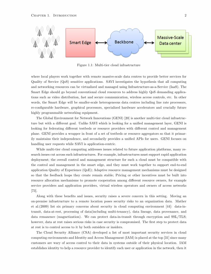
Chapter 1. Introduction 2
Figure 1.1: Multi-tier cloud infrastructure
where local players work together with remote massive-scale data centres to provide better services for
Quality of Service (QoS) sensitive applications. SAVI investigates the hypothesis that all computing
and networking resources can be virtualized and managed using Infrastructure-as-a-Service (IaaS). The
Smart Edge should go beyond conventional cloud resources to address highly QoS demanding applica-
tions such as video distribution, fast and secure communication, wireless access controls, etc. In other
words, the Smart Edge will be smaller-scale heterogeneous data centres including line rate processors,
re-configurable hardware, graphical processors, specialized hardware accelerators and crucially future
highly programmable networking equipment.
The Global Environment for Network Innovations (GENI) [20] is another multi-tier cloud infrastruc-
ture but with a different goal. Unlike SAVI which is looking for a unified management layer, GENI is
looking for federating different testbeds or resource providers with different control and management
plane. GENI provides a wrapper in front of a set of testbeds or resource aggregators so that it primar-
ily maintains their independence, and secondarily provides a unified APIs for users. GENI focuses on
handling user requests while SAVI is application-centric.
While multi-tier cloud computing addresses issues related to future application platforms, many re-
search issues cut across such infrastructures. For example, infrastructures must support rapid application
deployment; the overall control and management structure for such a cloud must be compatible with
the control and management in the smart edge, and they must work together to support end-to-end
application Quality of Experience (QoE); Adaptive resource management mechanisms must be designed
so that the feedback loops they create remain stable; Pricing or other incentives must be built into
resource allocation mechanisms to promote cooperation among different resource owners, for example
service providers and application providers, virtual wireless operators and owners of access networks
[73].
Along with these benefits and issues, security raises a severe concern in this setting. Moving an
on-premise infrastructure to a remote location poses security risks to an organization data. Mather
et al.(2009) list six primary concerns about security in cloud computing environment [44]: data-in-
transit, data-at-rest, processing of data(including multi-tenancy), data lineage, data provenance, and
data remanence (magnetization). We can protect data-in-transit through encryption and SSL/TLS;
however, data at rest raises serious risks in case security is compromised. The first step to protect data
at rest is to control access to it by both outsiders or insiders.
The Cloud Security Alliance (CSA) developed a list of most important security services in cloud
computing environments and Identity and Access Management (IAM) is placed at the top [31] since many
customers are wary of access control to their data in systems outside of their physical location. IAM
establishes identity to help a resource provider to identify each user or application in the network, then it
Chapter 1. Introduction 3
determines the identity of an individual or process (authentication), subsequently, it grants a correct level
of access to it based on context such as user, targeted resource, and environmental attributes. Various
models have been proposed to address identity management in cloud including central IAM, trusted third
party, federation solutions etc. However, these are not effective for a multi-tier infrastructure where all
resources are managed by applications. These prior architectures mainly focused on federation of cloud
providers, and paid less or no attention to access management. Despite these models effectiveness for
simple access management, such as an administrator delegating roles to users, they are not useful for
complex situations in a multi-tier cloud (e.g. an application wants to acquire a resource on behalf of an
administrator). Meanwhile, their heavy dependence on existing technology prevents deployment of new
techniques, and as a result, their mechanisms are limited to the chosen technology at the design time.
1.2 Motivation
The motivation of the thesis is to propose an architecture to handle identity and access management
in a multi-tier cloud computing. This architecture should be implementable on either private or public
cloud, and independent of underlying technologies, geographical distance, and be interoperable with
other infrastructure. Furthermore, it must maintain the positive features of cloud infrastructure such as
elasticity. To future-proof the architecture, it should be open so that it can adopt new authentication
and access management technologies.
1.3 Research Questions
Considering the motivation of this research and topics in background section, a research objective is
defined. The research objective is to design and implement an architecture for identity and access
management on Multi-tier cloud computing environments. This objective implies the main research
question of this thesis:
What are the required elements of a scalable, flexible, and technology-independent IAM
on a multi-tier cloud computing?
In order to answer the main research question, we pose multiple research questions:
• What are the various IAM architectures in traditional IT environments?
• What are the various IAM architectures in multi-tier cloud environments?
• What are the differences of the multi-tier cloud computing environments compared to existing
IAM technologies?
• What are the essential elements of a suitable architecture?
• What are the risks of the proposed architecture?
The first research question requires an overview of traditional IAM architectures and the different
technologies from the past. In the second question, we try to explain emerging technologies in identity
and access management, and consider their pros and cons in cloud environments. The third questions
explains our rationale to initiate this research, and identifies the deficiencies in existing solutions. When
designing a new architecture, some risks are introduced to the whole infrastructure, such as performance
Chapter 1. Introduction 4
overhead, bottlenecks, or new security risks. The last question explores these risks, and our solutions
to deal with them. The answer to the main research question can be obtained by answering all of the
above questions.
1.3.1 Challenges
The first challenge in designing this architecture is to keep components open to future technologies, this
technology can be in the backend, such as database, memcache, or LDAP etc., or in processes such as
authentication and authorization workflows. Decoupling backends from technologies, or even workflow
from a particular technique needs a well-defined abstraction layer. Components can be located at distant
locations and wrapped with web service APIs, or in the same node but with the access limited through
defined interfaces. At the same time, each component must be coherent in the sense of having all the
required functions to do its job. Performance and scalability considerations of the IAM bring about
some issues regarding the degree to which components should be distributed and abstracted. If IAM
is decentralized, we run into the challenge of data consistency and performance degradation, whereas a
centralized IAM jeopardizes the whole infrastructure by making IAM a bottleneck.
1.3.2 Research Barriers
The lack of commercial open source IAM is the first challenge. To test other architectures thoroughly, we
need to have access to their architecture or source code, and possible setup. Cloud providers and identity
providers have little interest to disclose their security architecture information, although they provide
general information about architecture or control processes. When a system is already implemented,
there is no practical way to determine the efficiency of individual features as we do not have real access
violation data. As a result, there is no accurate measurement to compare how much effective our
architecture is to others.
The second challenge is the required effort of implementation and the required expertise. Because
authentication and authorization is an essential element in all components in the cloud (e.g. computation,
storage, and network etc.), any changes to this process need to make proper changes in corresponding
components. Thus, developing IAM requires knowledge on the rest of the components as well, which
makes developing and testing a time-consuming and complex job.
1.3.3 Scope of Research
Identity and access management and cloud environments are two broad topics, so, considering all details
related to IAM is beyond the scope of this research. To complete the thesis and meet the research
objective, we define the scope of this research as follows: There are three types of delivery models in
cloud computing: Infrastructure as a Service (IAAS), Platform as a Service(PAAS), and Software as a
Service (SAAS). IAAS enables users to work with virtual resources such as virtual machine, storage, and
network directly while users can run their source code in PAAS, and SAAS allows them to use a prepared
application with no worry about support-related issues. Our IAM aims to address identity and access
management in a IAAS environment where all components serves users through web service technology.
Meanwhile, developing the inner authentication and authorization mechanisms are not considered part
of this research. In this research, we do not intend to develop a new algorithm for authentication or
authorization, and we use backend technologies such as database and LDAP etc. in full.

Chapter 1. Introduction 5
We consider federation of cloud infrastructures in our design section; however, the implementation
of such federation component to enable a cloud provider to be federated with other cloud providers will
be future work. We implement our IAM system for one administrative domain and one cloud provider;
however, we take federation into account in design section to allow IAM to be extended in the future. In
the Mel and Grance model [47], we are concentrating on a privately owned cloud for deployment model
and Infrastructure as a service for service model.
This research is taken from the point of view of a private cloud provider that wants to use an
IAM solution to provide identity and management service throughout all its nodes across Canada. The
requirements is gathered using literature review, and by discussing with SAVI design team.
1.4 Methodology
This research is based on the data gathered by literature review and identifying the new security risks
posed by multi-tier cloud architecture and applications requirements. The literature review helped us to
survey previous practices and theoretical background to recognize essential elements for our architecture
and find right mechanisms that fit into our components. We examine the architecture of a multi-tier
cloud infrastructure so that we can understand the components and their functions well. The second
step involves recognizing the traditional IAM architectures and models. Subsequently, to create a solid
theoretical framework, we perform a threat modelling to identify potential threats in this setting, and
then list the mitigation.
After crafting a concrete theoretical background, we intend to design and implement IAM. We re-
searched several methodologies that can be incorporated into our IAM development process. After an
intensive literature review, we decided to proceed with a Spiral Model because:
• Short development cycle allows to quickly develop a prototype and test it on a real system
• Interfaces between parallel development in other components must be compatible. Because our
testbed is based on service oriented architecture, failure in compatibility will result in system
failure.
• Anchor points milestone - our testbed has a milestone for each release, therefore IAM along with
other components must be evolved. To meet the milestones, we should use an iterative evolvable
approach.
• Our requirements are not fully clear at the beginning, and the underlying technology also constantly
changes.
Spiral model is a risk-driven software development and is based on the same premise of managing
risks by expanding capabilities through increments in an evolutionary manner [5]. Our Spiral model
has two distinguishing features, first it is a cyclic method for incrementally designing and implementing
IAM, the other one is a set of anchor point milestones to make sure we address the requirements.
1.4.1 Development Phases
Our development comprises five phases: requirements, design, implementation, testing, and deploy-
ment. During requirements phase, the goal is to determine the design requirements of the IAM system.

Chapter 1. Introduction 6
Requirements are the foundation to our system development. Vague, incorrect and incomplete require-
ments can jeopardize the project success. We receive requirements from several sources: previous IAM
requirements, interviews of the development team, threat modelling, and industry standards [42]. In
the design phase, we develop a conceptual architecture to address the requirements. Design provides a
bridge between requirements and implementation, and it plays a major role in developing this system
as most of security bugs find their origin in this phase [25]. Design is based on design principles, such
as Least Privilege, Fail Safe, Minimizing Attack Surface as well as and design patterns such as Factory
Class and Strategy etc. The output of the design phase identifies important components whose correct
functionality is crucial for IAM, along with components properties and the interaction between them.
This output gives an overall picture of IAM while ignoring detailed design and development. In the
subsequent spirals if we identify new threats or change in priority of a threat which in turn necessitates
changes in design.
In the implementation phase, we undertake to write a secure code to convert the design into a real
system. Next the implementation is debugged. The development process requires constant testing to
ensure that the new design does not break any functionality. We have two types of tests: security testing
and functional testing. In security testing, testers leverage threat modelling data, and create some misuse
cases to run on the software. Functional testing involves unit testing and integration testing where a
component is tested to ensure it works and does not break its compatibility with other components. The
final phase in our methodology is to deploy the IAM where the source code first goes through a security
review to identify any remaining security flaws, and then it is deployed on the server.
1.5 Organization of thesis
This thesis is divided into two sections: theoretical framework and practical architecture. Theoretical
framework creates a concrete mindset for our design decisions while the practical architecture deals with
the system development. As Figure. 1.2 demonstrates Chapter 2 and 3 comprise the theoretical frame-
work section. This section conveys the rationale of previous IAM designs and explores the architecture
of two open multi-tier cloud infrastructures. A clear understanding of multi-tier cloud architecture is
necessary to perform a comprehensive threat modelling in the next chapter. We survey the current threat
modelling approach, and choose one of them. After applying some changes to fit into our requirements,
we conduct threat modelling on the SAVI IAM. We identify potential threats, mitigation and attack
surfaces, and classify them into groups. This chapter gives the reader the rationale behind some design
decisions, where there is not well-known principle or design pattern in literature.
The second section designs the IAM architecture where each chapter maps to a spiral in the lifecycle
of our software system development. In chapter 4 (spiral 1), we gather all requirements, design principles,
and produce a preliminary design of our system. This design (as per Spiral methodology) is followed
by implementation. We implement the architecture with the simplest mechanisms for components e.g.
empty role in access management. Next we deploy and test the system on a real infrastructure. Although
there is no explicit part for requirements gathering in the following chapter, it is carried out before
each design phase. Chapter 5 concentrates on access management where we pursue an evolutionary
approach starting from Role based access control (RBAC), and wind up to a high-end authorization
method named Attribute Based Access Control (ABAC). In Chapter 6, we concentrate on scalability
and performance. We introduce some techniques to boost performance and enable the IAM to scale up

Chapter 1. Introduction 7
Figure 1.2: Research Structure
Chapter 1. Introduction 8
with the increasing number of the requests. We prepare the IAM to run on a production level environment
such as SAVI. We discuss approaches to boost the performance, and we identity the bottlenecks for this
architecture. We run performance measurement experiments to show our features have a reasonable
impact on performance compare to similar cases in our baseline of implementation or other identity
providers.
Future work deals with federation issue whose implementation is beyond the scope of this research.
We perform requirement analysis and develop a rough design. This chapter manages federating with
massive resource providers such as cloud providers (e.g. Amazon EC2 etc.) and other testbeds. We
discuss authentication and authorization in order to prepare a plan for our future work.
1.6 Contribution
In summary, this research makes the following contributions:
• We design a comprehensive architecture for a centralized IAM in a multi-tier cloud infrastructure.
• We propose three performance enhancing techniques of the IAM for scalability: load balancing,
caching, and middleware.
• We propose a fine-grained policy-based access control for trust-relationship management.
• To test our proposed IAM on the Canadian SAVI Testbed.
• Using the testbed, we have shown that the IAM outperforms the previously proposed IAM for
cloud infrastructure in throughput and response time.

Chapter 2
Background and Related works
2.1 Cloud Computing
The term cloud computing first appeared nine years ago when Amazon web-service was introduced,
but the idea of renting resources is not new; consequently, cloud computing has many antecedents.
Various definitions of cloud computing and its related applications have appeared in both in scientific
and business literature. The roots of cloud computing lay in the idea of computing as a utility (like water
and gas), and are closely related to the development of Grid computing. Vaquero et al. [67] attempted
to produce a standard definition of cloud computing:
Clouds are a large pool of easily usable and accessible virtualized resources (such as
hardware, development platforms and/or services). These resources can be dynamically
recongured to adjust to a variable load (scale), allowing also for an optimum resource utiliza-
tion. This pool of resources is typically exploited by a pay-per-use model in which guarantees
are oered by the Infrastructure Provider by means of customized SLAs.
Cloud infrastructure consists of three essential elements: the client, grid computing, and utility
computing. Grid computing incorporates multiple independent machines into a large network, allowing
computer resources to be efficiently managed. Clients can connect to this grid through a public network
such as the Internet. Utility computing is used to share resources between users and keep track of each
users usage, enabling the cloud to charge users for resource use on a pay-as-you-go business model.
Organizations may use cloud computing resources to process data, store information, enhance pro-
ductivity, and manage services such as accounting, communications, or customer service. The main draw
of cloud computing for organizations is that it eliminates the need for them to have their own dedicated
data centres. Instead, computing services can be provided on demand in a similar manner to traditional
utilities such as water and gas. Organizations pay only for the services they use in a pay-as-you-go
business model. For example, Amazon AWS clients are charged according to type of virtual machine
used, time of usage, and storage space used.
2.1.1 Cloud Characteristics
As with the very definition of cloud computing, essential characteristics of the cloud network also vary
from one provider to another. The National Institute of Standards and Technology (NIST) defines five
9

Chapter 2. Background and Related works 10
essential characteristics of cloud computing system [48]:
• On-demand Self-service: A client should be able to acquire or release resources without requiring
outside human interference.
• Broad Network Access: Resources should be available over the network, and a client should be
able to access resources through standard mechanisms by using thin (e.g. Smartphones) or thick
(e.g. PC) clients.
• Resource Pooling: Resources are pooled to serve disparate customers on the same or different phys-
ical machines. Resources can be dynamically assigned according to customer demands. Clients
should not be aware of the source location of lower-level computing services, but should be permit-
ted to specify higher-level locations (e.g. country of origin). Resources can include computation,
storage, networking etc.
• Rapid Elasticity: Clients can acquire, release, and scale resources in an elastic manner, making
the available resources appear unlimited from the clients point of view.
• Measured service: The cloud management layer constantly monitors, controls, and reports resource
use to both the provider and client, providing a metering capability.
2.1.2 Cloud Service Model
Commercial cloud computing services are typically divided into three service models, distinguished by
their level of resource abstraction [48]:
• Infrastructure as a service (IaaS): This model offers virtual resources to users. Users can
directly connect to computation and storage and run their own software using these resources.
In this model, the provider delivers the hardware (server, storage, and network), and associated
software (Hypervisor, Operating system, or file system). This model is similar to traditional
hosting services, but clients do not commit to any single resource, and can dynamically scale their
resource use. To deploy their applications, customers move an operating system image to a virtual
computing slice. In this model, customers often manage maintenance and patching themselves.
Amazon EC2 and Google Compute Engine are two examples of this model.
• Platform as a Service (PaaS): The PaaS provider delivers a platform on which a customer can
develop and deploy their codes. In this model, customers do not interact with virtual resources
directly. This offloads the burden of maintaining, patching and managing the underlying infrastruc-
ture to the PaaS provider. PaaS mainly comprises infrastructure, development tools, databases,
and some middleware. Scaling of applications is often carried out by the cloud provider, but in
terms of complex backend development such as data lineage, this model is extremely limited. The
two examples of PaaS are Google AppEngine and Herkou.
• Software as a Service (SaaS): SaaS the dominant cloud computing service model. In SaaS,
applications are hosted remotely by a service or an application provider, and provide service on
demand over the Internet. Clients share only their data with cloud provider. There are numerous
examples of SaaS such as Gmail, Google Calendar etc.

Chapter 2. Background and Related works 11
2.1.3 Deployment Model
There are four basic deployment models for cloud computing computing:
• Public Cloud: The public cloud is the most well-known cloud model. In this system, clients use
third-party resources in a fine-grained, self-service manner over the Internet. Resources are mainly
accessible through web applications or command-line interfaces. The cloud provider periodically
measures and bills used resources on a utility computing basis [57].
• Private Cloud: Private clouds provide organizations with their own dedicated data centres. The
main driver for the adoption of private cloud computing is for organizations to maintain greater
control of their data, an ability typically lacking in public cloud systems. However, this model
requires a certain level of engagement and expertise to set up and maintain. There are two types
of private clouds:
– On-premise: This is a cloud system which has been integrated into an organizations IT
process. An organization can use available software such as Openstack to run a cloud service
on its own hardware. This model is also known as an internal cloud, and provides the greatest
degree of control over a clients data. On-premise clouds are better suited for organizations
which desire greater configurability and control over their data infrastructure [70].
– External Private Cloud: In this model, a private cloud platform is hosted by an external
cloud provider, but with the guarantee of privacy. There are two strategies for creating a
private cloud on a third-party datacenter. The first is to create a separate zone with separate
physical machines. Such isolated networks on Amazon EC2 allow US Federal Government
agencies to move their sensitive data and computation to the cloud while maintaining com-
pliance with their own internal standards and regulations [27]. This approach is not feasible
for most private companies due high cost of setup. The second approach is to provide a bare
metal service to clients, whereby physical hardware rather than virtual machines are allocated
to customers [12].
• Hybrid Cloud: In this model, the cloud infrastructure consists of a combination of two clouds
(private and public). The Hybrid deployment model enables organizations to retain the data in the
private cloud while performing computation tasks on the public cloud. Therefore, the organization
combines the privacy of the private cloud with the infinite resources of the public cloud. Cloud
bursting is a common practice for expanding resources across multiple cloud or load balancing
between independent infrastructures. Cloud bursting allows an application to run in a private
cloud, but acquire additional resources from external clouds as needed. The advantage of cloud
bursting is that organizations can perform the vast majority of their computing on their own
private network, paying only for extra public cloud usage during peak hours [51].
• Community Cloud: In this model, the cloud infrastructure provides resources exclusively to
organizations with similar cloud requirements in order for them to work together and achieve their
business objectives. Such an arrangement might be managed by one of the member organizations
or a third party.
Figure 2.1 illustrates the organizational distinctions between the four different cloud deployment
models:

Chapter 2. Background and Related works 12
Figure 2.1: Cloud service model and deployment model
2.2 Cloud Security
While cloud computing demonstrates clear advantages, migrating to a cloud-based system poses se-
curity risks to an organizations data. Kandukari et al. [34] consider seven cloud security issues that
organizations should include in their Service Level Agreement:
• Privileged user access: Privileged user access ensures that only authorized users have access to
an organizations data and resources
• Data location: Data location risk considers the comparative security risk of storing and processing
data in one location (e.g. county) over another. The inherent level of uncertainty over where in
the cloud data will be stored necessitates the encryption of data before its introduction into the
cloud.
• Data segregation: Because of multi-tenancy nature of the cloud computing model, data from
different users can be stored in the same location. This creates the risk of breaches to the isolation
layer, which can compromise other users resources and data. There should thus exist a clear
boundary at different abstraction layers to segregate each users data.
• Data disposal: Because the data is located outside of an organizations territory, data loss is
always a risk. Therefore, cloud providers often keep multiple copies of data as backup. Data
disposal considers the risk of data remaining in the cloud after a user leaves, and ensures that all
unused data is wiped out.
• Recovery: Organizations must explicitly defines how data is recovered in the case of failure.
• Investigation: Investigation imposes contractual commitments on cloud providers to support
measurements of services and used resources.

Chapter 2. Background and Related works 13
• Long viability: Long viability assures users that data is available even after the contract is
broken.
Research challenges in cloud computing security can be divided into 6 categories [66]: Authentication
and identity management, access control and accounting, trust management and policy integration,
secure services, privacy and data protection, and organizational security management.
• Authentication and Identity Management concern the federation of cloud users identities, enhanc-
ing authentication, developing architectures, and the security of users identities. Data segregation
should be applied to users identities and personal information as well.
• Access Control and Accounting researchers propose access control models to protect users data
in the cloud. These models should be flexible enough to provide a fine level of access for users
and applications and to enforce the principle least-privilege and separation of duties. Such access
control must incorporate privacy-preserving requirements expressed through a set of rules. Some
researchers propose a policy-neutral access control framework for proper interoperability. Cloud
provider constantly perform accounting of users and applications to issue bills for them which
should not violate the privacy of users. Therefore, privacy is a major concern in both Access
Control and Accounting.
• Trust Management and Policy Integration address heterogeneity among the cloud provider poli-
cies and security frameworks. Applications might use multiple cloud providers to offer services;
therefore, security measurement is required to to ensure such a dynamic collaboration is managed
securely, and that security breaches are avoided during the interoperation process.
• Secure Service Management addresses quality of service, price, and service-level agreement in
service search and composition.
• Privacy and data protection is the core challenge in the cloud computing. Mather et al. [45]
list five main security risks to user data in the cloud: data-at-rest, data-in-transit, processing of
data, data lineage, and data remanence (magnetization). According to this classification, a users
data can be compromised in five different states: when data is in storage, traversing the cloud
network, processing in virtual machines, remaining in cloud after the user is left. To protect stored
data, users can use encryption algorithms. Users can use SSL/TLS to protect data-in-transit,
and homomorphic algorithms for data-in-process. Cloud providers provide provenance records to
track ownership and process history of data objects in the cloud [43] and ensure customers that
data is processed correctly. Provenance of information can be used for traceback, auditing, and
history-based access control [40, 72].
• Organization Security Management helps organizations to adopt cloud computing. When an or-
ganization moves to the cloud, new risks are introduced such as shared governance, availability
and incident handling, data leakage, resiliency issue, and insider attacks. This category of re-
search is mainly focused on developing life-cycle models, risk analysis and management processes,
penetration testing [36], and service attestation [11].
The remainder of this chapter concentrates on Authentication and Identity Management research.
In Identity Management, both traditional identity management models and existing solutions for cloud

Chapter 2. Background and Related works 14
computing are explored. Next, the concept of multi-tier cloud computing and the prototypes such
as Smart Application for Virtual Infrastructure (SAVI) and the Global Environment for Network and
Innovation (GENI) are considered.
2.2.1 Identity and Access Management
Identity refers to a set of user attributes, an application, or a thread of executions that helps distinguish
entities in the cloud from one another [1]. Identity management is a combination of processes and
technologies used to manage and secure access to data and resources, and to protect user information.
It is composed of two main processes: establishing an identity (which can be carried out during initial
registration), and user authentication. Identity establishment is the process of associating a user, running
process, or thread of execution with a legitimate cloud entity, and is the cornerstone of user access control
policy. Managing identities is a challenging task in cloud security, as organizations tend to use multiple
cloud providers for resource provisioning while maintaining a single identity in order to manage access
to these resources. The four parties are involved in identity management process are as follows [7]:
• Identity provider: issues identities, and manage identities in subsequent operations
• Service Provider: provides the service or resource for which a user must be authenticated
• Entity: makes the claim about an identity
• Identity verifier: performs authentication to verify the claim of an entity
To authenticate a user, the identity verifier makes use of one or more following factors:
• Information that both parties know, such as a password
• A token that a party owns which can distinguish its identity such as One Time Password Kit
(OTP).
• An attribute unique to the entity, such as biometrics (fingerprints, voice recognition etc.)
An identity manager should have the following capabilities in order to deliver identity services in
cloud computing [9]:
• Identity provisioning/deprovisioning: An identity manager should be able to assign and
revoke the identity of an entity in the cloud in a secure and just-in-time manner.
• Authentication: This is the process of determining the truth of a claim an entity makes about
an identity.
• Authorization and Entitlement: Entitlements are a set of attributes which specify the access
rights of an entity. Authorization uses these attributes to confirm or deny a request.
After identity is established, and procedures are defined, Identity Lifecycle Management should be
specified. Identity Lifecycle Management is the process of managing accounts, policy changes, and
entitlement, and tracking policy compliance. It includes the following features:
• Workflow: Steps in identity lifecycle management should be automated in order to decrease
administrative efficiency and reduce security risks by reducing human interference.

Chapter 2. Background and Related works 15
Figure 2.2: Identity Lifecycle Management [21]
• Delegation: Delegation is the process of granting permission to an application or entity to carry
out certain tasks in the future. Delegation is necessary in cloud as the majority of tasks and
processes are volatile and short-lived.
• Entitlement: Access control attributes should be clearly defined. For example, in Role-Based
Access Control (RBAC), roles must specified and the membership declared.
Figure 2.2 shows the lifecycle of identity management in a cloud computing environment. These
tasks are performed by two basic components: provision and administration. Provision components
manage identities and user profile information while administrative component mainly handles access
management.
Proliferation of User ID occurs when a user has multiple identities in multiple services - a common
occurrence on the Internet. Cloud federation refers to unionizing resources from different cloud providers
aggregated in a single pool to enable users to receive three interoperability services from the providers:
resource migration, resource redundancy and combination of complementary resources. Migration allows
the relocation of resources, such as virtual machine images, data items, source code, etc. from one
provider to another one. While redundancy allows concurrent usage of similar service features in different
providers, combination of complementary resources and services allows combining different types to
aggregated services. Federation plays an important role in deploying an application spreading across
multiple cloud provider or an application that is the composition of independently administered services.
There are two important barriers to effective federation: incompatible technology and trust issues. To
overcome these issues, service providers connect standard protocols such as Service Markup Language
(SAML) to create a complete trust model between the sender and receiver of an identity. To develop an

Chapter 2. Background and Related works 16
identity and access-management system, an identity management lifecycle should initially be specified.
Identity lifecycles are further discussed in Chapter 4. Although the SAVI identity lifecycle is similar to
Figure 2, it has adjusted to fit into our architecture.
2.2.2 Traditional Identity Management Model
In order to better understand the metrics of identity management in clouds, as described in later sections,
this section provides a detailed overview of traditional identity management models.
Isolated User Identity Model
In this model [32], the service provider issues identities to the customers and verifies the identity itself.
Therefore, a user receives multiple credentials and access permissions across different service providers.
The main advantage of this model is its simplicity for the service provider, while the main drawback is
the difficulty of managing multiple identities faced by the user. This approach increases security risks,
as users often choose the same password for all their accounts.
Federated User Identity Mode
To remove credential redundancy and prevent fragmented login, a new approach for federating identity
management of service providers has been proposed. Identity federation involves establishing agreements
between service providers to recognize each others identities in a federated domain. This agreement
defines the mapping of a users identity when they transfer from one administrative domain to another.
In this model, when a user is authenticated to access one service providers system, their identity is
automatically confirmed on a Single-Sign-On (SSO) across multiple domains [19].
Centralized User Identity Models
The Centralized User Identity model defines an identity provider which stores all user identifiers and
credentials. This identity provider is then used by multiple service providers to manage their users. There
are several possible implementations for this model, but here only the most common implementations -
the Meta-Identifier and Single Sign-On (SSO) models - will be examined.
The Common User Identity (CUI) model is the simplest way to implement a centralized model in
which a central node is dedicated to providing user identity and credentials. In this model, a user
can access all service provider resources using the same identifier and credentials. PKI is a typical
implementation of this model. The main challenge in implementing CUI is selecting a unique identifier
valid across all domains. Email addresses are a good example of such an identifier, but their security
can easily be undermined by changing the address or registering under a fake address [33].
In the Meta-Identifier model, each service provider identifier is mapped to a unique meta identifier.
Each identity provider issue its own identifier to users; however, credentials is shared between different
providers. When a user wants to authenticate himself to an identity provider, the identity provider maps
his identity to meta identifier. Then the identity provider checks the credential against the available
credential. In this model, user credentials are identical across providers; only the identifiers are different.
Users do not know about the meta identifier, which is an internal agreement between service providers.
This model is useful for integrating legacy identity management systems in organizations, and is effective
when all service providers are under the administration of one organization [13].
Chapter 2. Background and Related works 17
Single Sign-On (SSO) is an extension of previous models wherein a service provider delegates authen-
tication to another provider, which serves as the identity provider. This provider takes the responsibility
of issuing identities and credentials, and authenticating users. This model is similar to federation model
except that there is no need for identity translation. In the federation model, users identities must be
translated to an agreed-upon technology platform in order to be transferred to the second provider;
however, there is no such requirement in the SSO system since the transfer is performed by a single
entity [24].
User Centric User Identity Management
User-centric identity management offloads management of multiple credentials to the user side. It offers
automation and system support of the identity management process to users so that they can manage
various identifiers and credentials simultaneously. This model uses a Personal Authentication Device
(PAD) to store all credentials and identities issued by service providers in a dedicated piece of hardware.
A user must first authenticate themselves using a master set of credentials; the PAD then authenticates
the user to access the service providers resources. This PAD can also be a piece of software; the Keyring
application finds its origin in this model. Other devices (e.g. Smartphones, tablets) can incorporate
PADs as a built-in feature [32].
2.2.3 Cloud Computing Identity Management Models
Identity Management (IDM) in web services is experiencing a paradigm shift from an organization-centric
model to a trusted third-party model on the cloud. Third party identity providers allow both scalability
and flexibility to users and applications over the Internet. Traditional identity management models are
either user-centric or service-centric; however, these models cannot be used on a massive scale in the
cloud. Recent work on cloud IDM has focused on the general concepts of IDM, federation and decentral-
ization. Researchers have proposed various methods for addressing cloud-specific requirements such as
anonymous authentication to prevent disclosing information before being authenticated. Federation has
drawn more attention due to two main advantages: it enhances infrastructure usability for users, and it
eliminates the necessity of developing a new API for each identity manager or service provider. There are
three research challenges for federation: technical, informal (cultural), and formal (e.g. Legal) [23]. The
last research challenge is designing a decentralized architecture for identity management. Researchers
leverage two techniques to overcome this challenge: clustering identity-related activities and assigning
each cluster to a decentralized components. In this section, we proposed models for Cloud computing
IAM along with strategies to enhance IAM security and scalability.
Entity Centric Model
Angin et al. [2] propose an entity-centric approach for IDM in the cloud. The key elements in this model
are Active Bundles. An active bundle includes payloads, privacy policies, integrity checks and virtual
machines. Virtual machines is used to enforces policies. To make active bundle effective in cloud, this
model has to incorporate anonymous authentication, which means authenticating users before disclosing
the payload. It should also enable untrusted virtual machines to connect to IDM, and protect these
machines from side-channel [58] and correlation attacks. Providing anonymous identification prevents
Chapter 2. Background and Related works 18
a service provider from accessing to identity data before first identifying itself. This approach is inde-
pendent of the trusted third-party, and preserves the privacy of entities from service providers. This
model does not address the service registry and catalogue in an IAM service. The scalability of this
model is questionable because intermediates systems cannot cache entity data to boost performance.
This is a problem, since active bundles are large data packages. This model is comprehensive for the
web applications as these applications need maximum flexibility, and ultimate portability. In the cloud,
all service providers use standard APIs which makes flexibility in API definition useless. The second
drawback of this architecture is performance that is an important requirement in IaaS.
Bhargava et al. [56] propose an approach for identity management which is independent of the
trusted third party and has the ability to use identity data on untrusted hosts. The approach is based
on the use of predicates over encrypted data and multi-party computing for negotiating a use of a cloud
service. It uses active bundles, which are middleware agents that include personal information data,
privacy policies, a virtual machine that enforces these policies, and a set of protection mechanisms. An
active bundle interacts on behalf of a user to authenticate access to cloud services using a users privacy
policies. The drawback of using active bundles for authentication is that the active bundle may not
be executed at all on the hosted machine, resulting in a request denial. The users data, however, will
always remain protected.
Federation Model
In [26], a model has been proposed to address multilateral federation among cloud services, in cloud
applications and external services. This model proposes an identity federation broker that introduces a
trusted third party as a trust broker to simplify the management of identity federation in a user centric
manner. This federation broker enable transitive federation based on brokered trust model, and service
provider only needs to register once to broker to support potential federation with external services and
in-cloud apps. On the other hand, subscribers have full control over cross service access, which actually
triggers configuration over transitive federation between services in a transparent way. Moreover, the
solution can adopts different federation technologies (e.g. Shibboleth) and identity management systems
for service providers. The broker is providing attributes to provide a cross service access for the users.
Stihler et al. propose a federated identity management approach to support multi-domain clients
in a multi-provider environment [65]. This model integrates SaaS and IaaS layers while concealing the
details of identity management in the IaaS layer. This integration enables SaaS application developers
to track resource usage in a user-based fashion and apply security policies to individual users. This
architecture uses OpenID for SaaS application and OpenSAML toolkit for federation.
Celesti et al. [8] propose a IdP/SP-based architecture to address the heterogeneity problem in Identity
Management (IDM). The proposed distributed architecture consists of hundreds of IDPs interacting with
clouds authentication module. It uses SAML to create a trust-relationship between IDPs with different
security mechanisms. In this architecture, IDP in the service providers cloud acts as a third party,
asserting a foreign cloud and a foreign cloud Identity Manager.
Identity Management Solutions
Rackspace is one the major cloud providers, a commercial deployment of Openstack using Keystone
V2.0 for identity management. Keystone V2.0 is the baseline for our implementation as well. There are
some differences between Rackspace Keystone and Openstack Keystone in their respective URLs, and

Chapter 2. Background and Related works 19
request and response formatting. The Rackspace identity manager does not support policy management,
and its authentication mechanisms are password and API key [29]. The second major cloud provider is
Amazon. Amazon Web Service (AWS) Identity and Access Management (IAM) is a web service that
allows organizations to unify users and their entitlements management. It eliminates the redundant
burden of managing multiple users, and consolidates billing in Amazon. Applications can also obtain
a temporary security credential to send requests to Amazon services. Amazon IAM supports Google,
Amazon, and Facebook identity federation. Users can work with AWS IAM in four ways: Management
Console to browse and manage IAM and AWS resources through the web; Command-Line interface; and
AWS SDK to use the IAM programmatically in their applications; and Query API. The identity broker
in Amazon IAM is a portal to bridge web sign-on with a key-based system. Administrators divide users
into groups. Each group is associated with a policy file which defines the permissions. The policy file
can also attach to a resource (e.g. Amazon S3) to specify who has access to the resource. To grant
temporary access to users or services that normally don’t have access to AWS resources, Amazon IAM
supports role-based delegation, whereby one user can delegate access to AWS resources to another user
using IAM roles [28].
OpenID is an open-source, decentralized, user-centric digital identity management solution for web
services that provides seamless SSO that is compatible with existing internet technology (URL, HTTP,
SSL, Diffie-Hellman). OpenID V1.0 supports only stateful authentication, and OpenID v2.0 supports
both stateful and stateless authentication. OpenID can be integrated with cloud platforms (e.g. Open-
stack) to provide decentralized delegation for cloud services [?]. Users can keep their OpenID entity after
the identity provider is gone, making OpenID a flexible solution for delegating authority to applications.
However, OpenID is prone to phishing attacks, wherein users enter their credentials into webpage posing
as an OpenID provider website. Attackers can easily transform existing URLs into an account which
can be used at sites which support OpenID logins [60].
Shibboleth came out of the academic community through the Internet2, receiving much attention due
to its claim of eliminating the need for universities to authenticate users for an array of web resources.
It is an open-source implementation of Security Markup Language (SAML), which is used for federated
identity management and cross-domain authentication and authorization. In Shibboleth, there are two
entities: Identity Provider(IdP) and Service Provider (SP). These components are deployed separately,
but work together to provide secure access to cloud resources. Shibboleth is useful for organizations
and cloud providers for several reasons [52]: authentication is performed within the organization or
cloud provider, and the organization can control attributes released to the remote service provider. IDP
provides an identity for an entity which is used by SP to authorize a user. SP is a service or resource
on the cloud. Once an entity is authenticated to the identity provider, the IDP issues an assertion that
contains the entity attributes to present to the SP. This assertion shows that the entity is authenticated
to IDP, and because of the trust relationship between IDP and SP, the entity is authenticated to SP as
well. As a result, there is an identity federation between the identity provider and the service provider.
Shibboleth 2.0 is based on OASIS SAML. SAML uses attributes to represent an entity identity. The
only drawback to Shibboleth is its use of the same trust level for all services. Therefore, Shibboleth
discloses the same attributes to all services while in a real world, service have different level of trust to
know an entity attributes and secret information [49].
Privacy and Identity Management for Europe (PRIME) provides privacy-preserving authentication
using anonymous credentials. It takes a highly interdisciplinary approach in order to produce solutions
Chapter 2. Background and Related works 20
that are technically feasible, user-centric, socially acceptable, legally enforceable and commercially viable.
PRIME provides a consistent user experience for identity-related interactions with service providers.
The user-side component uses protocols for gaining third party (IDP) endorsement for claims to relying
parties (RPs). PRIME provides anonymous credentials by using a identity mixer protocol to enable users
to selectively disclose parts of their attributes in credentials obtained from IDP, without disclosing all
the information. IDP signs credentials with its public key to preserve the integrity of the endorsement.
A major limitation of PRIME is that it requires both user agents and SPs to implement the PRIME
middleware, which hinders standardization [6].
Higgins is an open-source user-centric trust framework and collaborative project for providing a
consistent user experience based on card icons for the management and release of identity data. As an
interoperability framework, Higgins provides an API and data model to virtually integrate and federate
identity and security information from various sources such as CardSpace, OpenID, and Liberty. Higgins
has two major components [17]:
• Lower-level components for creating identity services such as attribute services, token services, and
relying party Websites (i.e. service providers) and services.
• Upper-level components for creating user-centric applications which allow users to view, employ
and manage various identities (i-cards). More specifically, Higgins upper-level components can
be used to build identity agents which allow users to accept i-cards from card-issuing sites (i.e.
identity providers). These agents can be used to create self-issued cards, manage a users set of
cards, and to use these cards towards service providers (relying parties) or local applications.
2.3 Multi-tier Cloud
Multi-tier cloud architecture provides a model whereby cloud providers can provision flexible and reusable
resources. By segregating a resource type into tiers, cloud providers gain the option of modifying or
adding a specific resource rather than offering a resource from scratch. A two-tier architecture is typically
composed of a management tier, and a data tier. Figure 2.3 shows the general layout of a three-layer
cloud architecture:
The terms layer and tier are often used interchangeably, but in the literature layer refers to logical
structuring while tier refers to the physical arrangement of the system infrastructure [5]. The topmost
layer is a node layer, where each node can offer its own configuration and resources. For example, a
cluster can offer NetFPGA while this resource is not available in another datacenter. The second layer
is data layer which includes all resources shared between various nodes in a different datacenter such as
computation, networking, storage, and images etc. This tier addresses general application requirements
(e.g. processing and storage); application with special requirements are handled on the node tier. The
last and lowest tier is the management tier, where measurement and management services are offered to
applications and resources. Identity and Access management, resource and service registry, monitoring
and measurement, and resource allocation are examples of services in this tier. The management Layer
is the furthest tier from the client, while the node tier is the closest. This reference model has several
advantages, including [35]:
• Resource can be load balanced separately.

Chapter 2. Background and Related works 21
Figure 2.3: Multi-tier architecture
• Adding or modifying resources in nodes is independent of the rest of architecture.
• Deployment of new resources is faster and easier
The prominent characteristic of this reference model is asymmetry; each node can have its own set of
resources. Each node can be a cloud provider, a cluster, or a set of servers. There are two implementations
of this reference model: Smart Application for Virtual Infrastructure (SAVI) in Canada, and the Global
Environment for Network Innovations (GENI) in US. In the rest of this chapter, the security architecture
of this platform is examined.
2.3.1 Smart Application on Virtual Infrastructure (SAVI)
The SAVI Testbed is a platform for designing, prototyping, and demonstrating an application-platform
testbed for experiments on Future Internet architectures, protocols, and applications. SAVI tries to build
a large-scale nation-wide Canadian application platform testbed. As Figure 3 depicts, SAVI testbed
consists of five major elements:
• Core Nodes: these provide resources for applications and are located in massive data centres. The
Core Nodes are accommodated by conventional cloud computing resources (computing, storage,
and basic networking), while Edge Nodes include more advanced resources such as re-configurable
hardware.

Chapter 2. Background and Related works 22
Figure 2.4: SAVI architecture
• Smart Edge Nodes: these provision resources for applications and are located near Access
Nodes. Examples of these resources are computer, storage, network, optical access, wireless access,
and re-configurable hardware resources (e.g. BEE4 and NetFPGA). Core and Smart Edge nodes
together are referred to as the Extended Cloud in SAVI.
• Access Nodes: these enable users to connect to the SAVI network through wireless access points.
• SAVI Network: this connects Core Nodes and Edge Nodes together
• TB Control Centre: the management layer of SAVI.
In the current deployment of SAVI, Edge Nodes are deployed on sites in participating universities
(e.g. University of Toronto, York University). Some universities also deploy an Access Node; therefore
it is not necessary for them to have Edge Node as well.
As SAVI aims to be both a research testbed and a cloud provider, it supports both applications and
experiments. In SAVI terminology, applications deliver a feature to end users and need to guarantee an
agreed-upon level of service, while experiments are comparably short-lived, used by a researcher, and
aimed at gathering measurement data or user feedback. In practice, however, both applications and
experiments are treated equally in SAVI TB, and are used interchangeably in this document. To use the
SAVI testbed, applications send a request for resource slices to the SAVI Control & Management plane,
where this request is addressed by allocating a virtualized resource to the application. In addition to
serving such requests, the SAVI Control Centre performs authentication, authorization, and accounting
- all of which are bundled in the Clearinghouse component. Clearinghouse is a design principle borrowed
from GENI and Amazon to make security-related tasks more effective and efficient.
Figure 2.4 shows the overall architecture of SAVI testbed, in which Edge and Core Nodes are dispersed
in various geographical locations, and a SAVI dedicated network connects these elements together. Each
edge node can have access points, and all nodes can use SAVI TB Control Centre services through the
AVI network.
Figure 2.4 also shows how two sample applications (A & B) that run SAVI TB. These applications
obtain a slice of Core Node, Edge Node, and Access Node resources. In this figure, application X,
represented by a triangle, uses virtualized resources in all Core Nodes and Edge Nodes (except one

Chapter 2. Background and Related works 23
Figure 2.5: SAVI Logical Structure
Edge Node). The number of resources used by each Application is depicted by the size of triangle (for
Application X). For instance, Application X uses more resources in one of the Core Nodes and Application
Y (represented by circle) uses more virtualized resources in the other Core Node. SAVI nodes are also
securely connected to the Internet to access outside resource. However, for simplicity these connections
are not depicted in Figure 1. In the next section, we describe each of these components and their
respective responsibilities.
The logical structure of SAVI consists of two tiers, as depicted in Figure 2.5. The C & M tier performs
resource allocation and secures a slice of virtualized resources for the application. The application
then runs in the A & E plane over the allocated virtual resources throughout SAVI TB, including any
combination of Edge Nodes, Core Nodes, Access Nodes, and network resources. The SAVI-TB C & M
plane is also responsible for traditional FCAPS management tasks (Fault, Configuration, Administration,
Performance, and Security), as well as control related tasks such as on-demand allocation/de-allocation
of virtualized resources to/from experiments and applications. The main advantage of having such a
tiered structure is to enable applications to control their management tasks, including resource allocation.
In SAVI, applications can run their own resource allocation algorithms in the management tiers where
the algorithm can optimize allocated resources. Researchers can run their experiments or applications
on the A& E plane, which is a set of allocated virtualized resources for that project (i.e.. applications
or experiments). This plane allows applications to follow any desired architecture (e.g. P2P, Star
topology) to address their design requirements. SAVI enforces the minimum constraints on the internal
architecture of applications. To facilitate application development and expedite creation of cloud-based
apps (particularly short-lived apps), SAVI provides certain software components that can be used by
developers to rapidly deploy their applications.
SAVI deploys the above logical components in the following manner: node-level components are
placed on their corresponding nodes while C&M components can be distributed throughout the testbed
or centrally located at nodes.
Figure 2.6 shows the component diagram for SAVI TB, and how they are linked together. Users
can use SAVI web portal or command-line clients to access SAVI resources. There is a Monitoring
and Measurement component that provides a metering capability for SAVI resource status in real-
time. This data is presented to both researchers and resource providers. This component operates
in publish/subscribe mode, meaning that resource providers or researcher must subscribe for data,

Chapter 2. Background and Related works 24
Figure 2.6: SAVI component diagram
which is sent to them when it becomes available. The Network Manager is responsible for managing
virtual networks and external connectivity. A virtual network in SAVI TB is an isolated slice of the
substrate network, which is allocated and configured as a part of the resource allocation process. The
substrate network connects different campuses. Each zone is an OpenFlow-enabled network, operated
using a logically-centralized controller. The SAVI Network Manager orchestrates these in-zone OpenFlow
controllers to create a single logical network.
As shown in Figure 2.6, the SAVI framework and SAVI Clearinghouse are directly connected to
security management in SAVI. In the rest of this section, these components are described in detail.
SAVI Secure Framework
The SAVI TB secure framework is responsible for providing the framework in which all SAVI TB com-
ponents can operate and interact without any violations. It includes functionality that are required by
all (or many) components such as middleware, as well as API and Web Portal processing. All SAVI
TB components based on this framework run independently (i.e. are loose-coupled) and communicate
with each other asynchronously. Researchers or other external entities can see a SAVI TB service list
(an access control list of each service) via a web portal or application. The framework also acts as
a distributed container that hosts different SAVI TB components and facilitates their communication
through the middleware. This framework should be secured by a strict access control/authentication
mechanism to deny access to SAVI TB components by malicious users, and by an optional encryption
mechanism (e.g. a Secure Socket Layer (SSL)) to ensure confidentiality of communication with SAVI
TB components. The framework should also provide a warning message to the researcher or other com-

Chapter 2. Background and Related works 25
ponents and stop the experiment or application in the event of any operational or management problems
with SAVI TB.
The SAVI C&M Web Portal provides a SAVI TB service list, control for the & management status of
the SAVI TB, and an access control list. The SAVI C&M Application also provides the same functions
as the SAVI C&M Web Portal using PC or smart devices. SAVI C&M API provides general interfaces
for accessing SAVI TB C&M. An Access Control Manager manages subscribers and their access control
list. This framework provides a message-oriented middleware for asynchronous communication between
different components by handling both request-response and notification-type messages. A message bus
is used to enable access to different SAVI TB components through various protocols such as ActiveMQ,
XMPP, AMQP, Web Services, and Email. The enterprise service bus such as OpenESB, Apache Ser-
viceMix, or Mule can be used on the SAVI C&M Container for designing and implementing interaction
and communication between mutually-interacting software components in service-oriented architecture.
All SAVI TB components can be easily enabled or disabled without any interruptions to the system at
run-time.
2.3.2 The Global Environment for Network Innovations (GENI)
The Global Environment for Network Innovations (GENI) [20] is a testbed for prototyping and demon-
strating virtualized network experimentation. Like SAVI, GENI has control framework to manage re-
source allocation, discovery and optimization. Unlike SAVI, however, which requires a unified manage-
ment layer, GENI allows resources to have their own management layers even with different control
frameworks. Protein [55] and Exigent [15] are two control frameworks proposed for GENI implementa-
tion. There are seven main requirements for GENI:
• Generality: GENI must place minimal constraints on researchers and developers in terms of data
format, functionality, and paradigm. It should incorporate a broad range of networking protocols
and technologies.
• Slice ability: As GENI is a cloud, it should support multi-tenancy solutions (supporting multiple
applications or experiments in parallel); while also guaranteeing their isolation.
• Fidelity: GENI must offer different levels of abstraction, allowing researchers experiment and
invent without having to build anything from scratch. GENI should also define topology in the
nodes and spread them geographically to represent the size of a real-world environment and provide
network-wide abstraction.
• Real Users: GENI aims to run real applications that serve real users, so it should encourage
long-lived useful applications.
• Research Support: Developing tools to increase GENIs ease of use.
• Observability:GENI control framework observes and measures resources and activities
• Sustainability: developing new technologies for GENI partners and supporting technology roll-
over without disruption.
In Figure 2.7, a researcher can log into the system using credentials in one of the federated organi-
zations with GENI. Then, the researcher can create a slice of resources in a desired physical location

Chapter 2. Background and Related works 26
Figure 2.7: GENI Architecture
and run the experiment. One of the design principles of GENI is to keep the core (the fixed univer-
sal point for all the nodes) minimal. GENI defines federation as the interconnection of independently
owned resources in order to enable researchers create and populate slices and run experiments on them.
According to this definition, resources can be federated into the GENI framework in two ways: as an
aggregate (shown in figure 8), or as a suite that is managed and administered independently.
ExoGENI is an implementation of the GENI control framework, which provides resources such as
computation, storage, and networking to researchers [4]. ExoGENI uses OpenFlow-enabled hybrid
Ethernet switches and cloud computing software such as Openstack. Figure 2.8 shows how ExoGENI
combines off-the shelf components and services to provide resources for GENI users. GENI users can
access the testbed through GENI API or ALT-G API. Open Resource Control Architecture (ORCA [?])
allocates and tracks resource slices by orchestrating the calls to a handler plugin. The handler plugin
calls the appropriate APIs from the resources provider in the IaaS layer. GENI follows a multi-tier
architecture in which the Testbed substrate provides the hardware used by the IaaS layer to provide
services. Then, the GENI layer wraps all APIs into a unified set under the name of GENI APIs. A
slice may span multiple ExoGENI, and the researchers can link them or other external resources via a
service-level agreement. Each ExoGENI site is a small IBM cluster integrated with OpenFlow switches.
Each rack in ExoGENI site runs a FlowVisor [63] that mediates access from the OpenFlow controller
to the OpenFlow data plane. When a slice wishes to set up OpenFlow controller to manage traffic on
its local data plane, ORCA calls FlowVisor to allow the controller to manage the traffic. User requests
are sent to control resource allocation. As with SAVI, ExoGENI control nodes run on control servers,
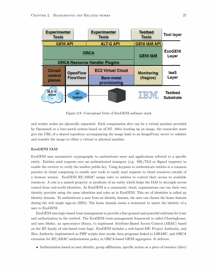
Chapter 2. Background and Related works 27
Figure 2.8: Conceptual View of ExoGENI software stack
and worker nodes are physically separated. Each computation slice can be a virtual machine provided
by Openstack or a bare-metal system based on xCAT. After booting up an image, the researcher must
give the URL of a shared repository accompanying the image hash to an ImageProxy server to validate
and transfer the image to either a virtual or physical machine.
ExoGENI IAM
ExoGENI uses asymmetric cryptography to authenticate users and applications referred to a specific
entity. Entities send requests over an authenticated transport (e.g. SSL/TLS or Signed requests) to
enable the receiver to verify the senders public-key. Using keypairs to authenticate entities is a common
practice in cloud computing to enable user tools to easily send requests to cloud resources outside of
a browser session. ExoGENI RT/ABAC assign roles to entities to control their access to available
resources. A role is a named property or predicate of an entity which helps the IAM to decouple access
control from real-world identities. As ExoGENI is a community cloud, organizations can run their own
identity provider using the same identities and roles as in ExoGENI. This set of identities is called an
identity domain. To authenticate a user from an identity domain, the user can choose the home domain
during the web single sign-on (SSO). The home domain issues a statement to assert the identity of a
user to ExoGENI.
ExoGENI uses logic-based trust management to provide a fine-grained and powerful solutions for trust
and authorization in the testbed. The ExoGENI trust-management framework is called Clearinghouse,
and uses libabac, an open-source library, to implement Attribute-Based Access Control (ABAC) based
on the RT family of role-based trust logic. ExoGENI includes a web-based IdP, Project Authority, and
Slice Authority implemented as PHP scripts that invoke Java programs linked to LIBABC, and ORCA
extension for RT/ABAC authorization policy in ORCA-based GENI aggregates. It delivers:
• Authorization based on user identity, group affiliations, specific action on a piece of resource (slice)

Chapter 2. Background and Related works 28
• Support for delegation permissions such as capability-based access control for slices
• Flexible declarative authorization policies and delegated policy evaluation
The trust logic provides a general language for constrained delegations of trust, and a logic-based
policy framework for reasoning delegations and local policy rules. A logic is a combination of language
and inference procedures used to express facts and rules that are applied to requests. In RT/ABAC,
each resource has policies which control which users are authorized to perform certain actions. Each
resource has a local inference engine to generate facts and rules. The resource grants trust to each entity
if the inference engine authorizes the action based on the facts and policies. Slices of a resource is the
granularity of authorization and accountability. If an entity is authorized to control a slice, it can control
any virtual resource in the slice which removes the overhead of defining a separate policy for each virtual
resource.
ExoGENI uses existing external identity services (e.g. Shibboleth) to provide a federated infrastruc-
ture with cloud systems to serve user communities spanning multiple campuses and across-organizations.
Shibboleth and other SSO systems support federated identities in order to enable a cloud provider to
locate an entity home domain and IDP, and establish trust relationships with IDPs that are verified by a
federated identity root. For example, InCommon Federation in GENI endorses the IDPs of its members.
The resource provider delegates trust to the InCommon federation root, and the resource provider can
add a policy rule to accept credentials from any IDP endorsed by the root, even if the IdP is not known
in advance.
2.3.3 Conclusion
Current approaches to cloud IAM focus on offering solutions for federation and access control. The lack
of a comprehensive analysis - from conception to physical implementation - of the proposed solutions has
resulted in impractical and fractured models. Meanwhile, some aspects of current access management
problems are specific to advanced cloud platforms such as SAVI. For example, infrastructure users can
acquire a set of virtual resources to run their applications, or an application can send requests for
resources on behalf of users. A virtual resource can span multiple providers in different geographical
locations or under another administration. This research focuses on designing and implementing a
comprehensive architecture that meets multi-tier cloud requirements such as SAVI. The following features
distinguish this work from previous works:
• SAVI IAM is used as a reference architecture to host a variety of mechanisms for authentication
and authorization.
• The goal of SAVI IAM is not to define a new model of authentication or a novel access control;
however, it use all the previous technologies to improve the security in the SAVI testbed.
• The IAM is technology-independent.
• SAVI IAM leverages the common management layer of SAVI to optimize the internal authentication
process.
• The proposed architecture should not require any changes on the resource providers.
Chapter 3
Threat Modelling
3.1 Introduction
With fast pace advent of cloud computing and associated applications, security takes more and more
attention. Any application needs a model of computation, a model of storage, and a model of com-
munication, and a model of security. Multiplexing the virtual resources of disjoint users on the same
physical hardware is necessary to achieve elasticity, and the illusion of innite capacity requires each of
these resources to be virtualized to hide the implementation of how they are multiplexed and shared. It
is conceivable that a users virtual resource could be co-located by its adversary which in turn engenders
a new set of threats (e.g. side-channel [59]) and might violate customer security triad (Confidentiality,
Integrity, Availability). When selecting security measures, the system designer must take the design of
the entire system into account, and not incorporate security technologies at random, in other words,
they should follow security engineering process.
Systems security engineering is concerned with identifying security risks, requirements and recovery
strategies. It also involves a process through which security designers develop security mechanisms and it
should be incorporated into system design process. Security Engineering has three main steps: modelling
threats, gathering security requirements, and developing security mechanisms. Each stage of security
engineering provides feedback to the previous stage and subsequently to all preceding stages. Threat
modelling and security requirements are the fundamental building blocks to the rest of security system
is built.
Identifying threats helps security designer to gather a proper security requirement list. This step
is very important when the definition of security for a system is faulty. Threat modelling or threats
identification tries to see the system from an adversary’s perspective to protect system assets. Despite
the critical of threat modelling in security design of a system, little effort has been dedicated to it
comparing to other aspects of system security. There are several existing methodologies on threat
modelling and many more on requirement engineering including: fault tree, attack net, attack trees,
Microsoft’s threat modelling, but most of them lack enough expressiveness and fail to embrace the new
requirements and semantics of software defined infrastructure to enable reasoning about threats.
29

Chapter 3. Threat Modelling 30
3.2 Threat Modelling Techniques
In order to model threats on Software defined Infrastructure we need to look at different threat modelling
techniques. We use these models to provide a handle to create a more ideal solution. We will go through
different techniques and explain their pros and cons.
Fault Tree
Fault tree is the graphical representation of failure analysis which leverages Boolean logic to show the
interconnection of a series of low-level events to undesired states of the system. A node in this tree
represents an event and trajectories are casual relationship of events stated in Boolean logic. Leaf nodes
are system events while intermediate nodes are hazards where the reliability and availability is required.
Each node can have OR or AND connection to the previous node in the hierarchy which can be translated
to the requirement of co-occurrence of two events if they want to succeed. For example, if you want to
run a virtual machine you should be authenticated and authorized to boot up a virtual resource. In OR
connection, event success is independent of individual success while depends on both failure.
Attack Tree
The term Attack Tree was introduced by Schneier [62], and in theory, is very close to Threat Tree and
Fault Tree. Attack Tree is a directed graph that describes how a system can be compromised. Each node
represents a goal, and root is the overall goal. An attacker should achieve the intermediate goal in order
to accomplish the higher goal while leaf nodes represents atoms of an attack. Figure 3.1 shows the partial
attack tree for Aurora Operation [69] which was a cyberattack conducted by an Advanced Persistent
Threat (APT) in China with ties to People’s Liberation Army. Each path maps to an attack strategy,
the dotted line in Figure 3.1 shows IE vulnerability attack where user download a rootkit malware that
leverages IE zero-day vulnerability to infect the machine, then the malware is able to crack administrator
password, and by elevating the privilege, it can access to valuable information which is the ultimate goal
of attackers.
Fault Tree, attack tree, and threat tree lacks adequate semantics to express reasoning about threats
such as Trust. They can not express attacks as they are unable to capture atomic details about APIs,
and shared resources. They do not indicate internal attack structure, events impact, or how attribute
can be synthesized.
Ptri Net
McDermott [46] tried to describe an attack using the strength of Ptri Net by separating data and
processes. In this approach, he defined attack as a Petri Net with a set P, P=p1,p2,p3,...,pn as Places,
and a set T, T=t1,t2,t3,...,tn as transitions. Each place represent a state of knowledge base, and each
transition is an event or action. Places are connected to transitions through unidirectional arcs which
represents their relationships.Each attack net is represented by a set of tokens S which can move from
one place to another place along an arc which can be translated to the progress of attack.

Chapter 3. Threat Modelling 31
Figure 3.1: Operation ”Aurora” Hit Google (Mid. 2009 Dec. 2009) [68]
3.3 Threat Modelling
SAVI is currently designing a national testbed for creating and delivering future internet applications.
This testbed will provide a flexible, virtualized, and converged infrastructure to support experimental re-
search in application-oriented networking, cloud computing, integrated wireless/optical access networks,
and future internet architectures. This diversity of facilities make the testbed an enticing target for
attackers; therefore, careful attention must be paid to design in order to ensure security. Due to its
similarities to GENI, the SAVI threat model is not substantially different from GENI in the abstract
viewpoint. However, specific implementation strategies and different components goals, and their secu-
rity requirements expose the architecture to several challenges. To model potential threats, the trust
level to each group of users - and corresponding attack types - must be defined.
Figure 3.2 - rings of threats to the SAVI architecture. At the centre is the infrastructure with the
greatest privileges. Outer rings represent progressively less-privileged users: SAVI researchers, opt-in
users using SAVI resources, and outsiders, respectively.
As relates to threat modelling, SAVI infrastructure comprises of four main components: Control &
Management, Core Framework/Container, Smart Edge, and the SAVI Network Manager. These four
main components are identified as privileged components which can interact with various components in
SAVI. Any software running on top of these components - excluding researchers applications - fall into
this class of threats. Moving outward, resources allocated to researchers, currently-running experiments,
and usage behaviours of allocated resources are taken into account. In perfect isolation, a threat in
this class results in less serious consequences than a threat at infrastructure level because the threat is
alive as long as the resources are not deallocated. The next layer belongs to opt-in users who hold less
privileges and, consequently, pose fewer risks to the SAVI TB. User network traffic and software fall in
this class.
A user may run an application on-premise and wield the application with a researchers application on
SAVI TB. Finally, as SAVI tends to connect to current internet architecture, it is susceptible to endemic

Chapter 3. Threat Modelling 32
Figure 3.2: SAVI Trust Level
internet Malware. Threat modelling was conducted using the same process suggested by Suvda Myagmar
et al. [50], which consists of the following three high-level steps: characterizing the system, identifying
the assets and access points, and discovering threats. Although the same process was employed, the
sequence of execution is different.
3.3.1 SAVI Characterization
We characterize SAVI with the following features:
• Point of Entries: Users can interact with from three point of entries: admin, internal, and public.
Admin entry is connected to the management network, and only top administrators and topmost
trustworthy components can connect to this network. Any breach to this network results in SAVI
testbed crash. The second entry is internal network which can be accessed by virtual resources in
the same node or other SAVI nodes. This network has the medium level of trust because identity
of users have been verified. The last one is public entry which is connected to the Internet. People
who interacts with this entry may not have any identity. Therefore this entry brings about the
most risks to SAVI.
• Access Points: Regardless of resources functionality, their interfaces are protected by the IAM
middleware. Users can not bypass the middleware unless the resource defines an object Public.
Access policies are defined by administrators at the IAM. There is always the risk of unauthorized
access to resources due to poor policy definition by administrators, or misconfigured resources.

Chapter 3. Threat Modelling 33
3.3.2 SAVI Asset
Assets in SAVI can be divided into three classes based on the owner of the asset:
• User Asset: Users have two set of assets on SAVI: data and resource. Users stores their credentials
in the IAM, files in the storage. Their data in process can also be in risk if an attacker can get
into their virtual machines. The second users asset is their resources that they pay for them. An
attacker can compromise users resources to launch an attack against an internal target or external
target.
• System Asset: There are plenty of resources on SAVI testbed that have not allocated to any users
yet. These resources are considered as system asset. These resources are always enticing targets
for an attacker. To gain the control of these resources, attackers need to access the management
network. Attackers can escalate their privilege to the SAVI administrator through the management
network. Therefore, the management network is considered as the most important asset for SAVI.
3.3.3 SAVI Threats
There are two main classes of attacks which must be addressed by the SAVI security framework. The first
class consists of attacks that abuse SAVI resources to perform malicious activities against resources or
principals outside the SAVI cloud. Although these attacks are difficult to launch, their severity justifies
their classification in a separate category. Denial of Service (DoS) attacks [30], spamming [41], botnets
[16], and Malware injection (e.g. BluePil [54] and Subvirt [39]) are typical examples in this category. It is
often difficult to detect such attacks, as distinguishing these anomalies from normal system behaviour is
not always feasible. The second category includes attacks conducted on SAVI resources and applications
to gain control of the SAVI network or disrupt the functionality of an application. These attacks can be
initiated by a rogue experiment or a malicious attacker. Cloud computing is intrinsically an adversarial
environment, thus a deciency in the virtualization layer may result in a breach in the isolation boundary.
For example, an attacker can place his virtual machine on the same physical machine as the target virtual
machine [11], and open a side channel to perform a timing analysis on the SSH keystroke [12]. Thus, the
attack is conducted from one virtual machine upon another without the direct intervention of hackers.
Another attack type is one which compromises a user assets security triad (Condentiality, Integrity,
Availability). User assets include user meta data information (e.g. credentials [13]), intellectual property
( e.g. data and software [11]), and resources (e.g. computation, storage, and network). Therefore, a
level of isolation between applications is required.
The following section lists specific threats that SAVI clearinghouse must address. This list was
compiled by studying the literature and estimating the likelihood of each potential occurrence. For
example, user account hijacking (i.e. session riding) is a likely incident in SAVI testbed because SAVI
researchers often do not properly protect their credentials. Determined attacks against SAVI components
are less frequent. The list of likely threats includes both attacks which can be launched exclusively or in
concert with other threats as part of a larger systematic attack. The SAVI testbed should continue to
function even while countering such attacks. Therefore, like GENI, SAVI requires a kill switch to quickly
and completely suspend a misbehaving application or experiment to prevent a single disruption from
spreading throughout the system. For example, if spammers were to subvert SAVI, causing Spamhaus
to blacklist one of the SAVI IP addresses and cause a major service disruptions, the SAVI administrator

Chapter 3. Threat Modelling 34
can use the switch to suspend the testbed and allow the rest of the system to proceed unimpeded. A
constant auditing feature should be incorporated into SAVI in order to monitor the components; if the
activities of a specific component cannot be sufficiently monitored, the administrator should then be
able to restrict the activities to that component. For example, if there is a unauthorized access to a
component in the management network - especially components invisible to the monitoring and auditing
plane - the administrator should constrain communication between this component and the Internet.
The following list outlines the main security challenges currently faced by SAVI:
• Shared Technology Issues: applications and experiments may escape isolation boundaries in
order to disrupt the execution of other applications within SAVI or obtain information about other
applications or experiments. Because clouds implement a multi-tenancy model, it is likely that
an application is co-located by an adversary. To clear a boundary between virtual resources, a
virtualization hypervisor mediates access between them. However, even hypervisors exhibit flaws
that can enable virtual machines to gain inappropriate levels of control or influence on the co-
located virtual machines. Such a flaw [59] exposed a vulnerability in Amazon EC2 that allows an
attacker to place a virtual machine (VM) on the same physical machine as a targeted VM and
construct a side channel between two VMs on the same physical machine, enabling a SSH keystroke
timing attack [64].
• Account Hijacking: An attacker can hijack a users account in three ways: stealing user cre-
dentials, session hijacking, and session riding. It is common within the security community for
users to be careless with their credentials, allowing them to be easily stolen via social engineering
tactics. Session hijacking refers to the use of a users session key to gain unauthorized access to the
information within the cloud, while session riding involves hackers sending commands to a cloud
service on behalf of the targeted researcher by sending the user an email or tricking the user into
visiting a specially crafted website. Attack methods such as phishing, fraud, and exploitation of
software vulnerabilities fall into this class of threat.
• Escalation of Privilege: This threat concerns attackers taking advantage of flaws in software to
grant themselves elevated access to the cloud and its associated data and applications. Because
SAVI is an on-demand resource-provisioning infrastructure, it provides some interfaces to users and
application to acquire or release resources, and some other management interfaces in management
plane to configure this resources. An attacker can escape the users trust boundary and gain
unauthorized access to these interfaces. The likelihood of such attacks is greater for SAVI than for
traditional systems, where these interfaces are available to administrators. Attackers can use their
privilege to disrupt other applications or experiments, or evade metering and billing.
• Vulnerability of SAVI Software Stacks or Procedure: The first challenge to maintain the
SAVI testbed is software patch management. A major vulnerability of SAVI lies in its software
patch management. SAVI uses Openstack to provide virtual resources to users. Openstack compo-
nents are under constant development, with the source code changing daily. When a vulnerability
is discovered in these components, it should be fixed immediately; otherwise, it might be exploited
by attackers. One important step is to actively manage all SAVI nodes i.e. proactively keeping
all software stacks up to date with known security patches. The SAVI components should also be
configured with the minimum number of open ports. In addition, an intrusion-detection system

Chapter 3. Threat Modelling 35
is also necessary for the continuous monitoring of anomalous nodes by the SAVI Clearinghouse.
Internet protocol vulnerabilitiessuch as those which permit man-in-the-middle attacksare there-
fore also relevant to SAVI security. Another major vulnerability lies in poor key-management
procedures. As noted in a European Network and Information Security Agency study, users use
keypairs to strengthen their account authentication, and encrypt the data in the cloud with their
Public/Private keys. Therefore, cloud computing infrastructures require the management and
storage of many different kinds of keys. Finally, advances in cryptoanalysis can render any crypto-
graphic mechanism or algorithm insecure as novel methods of breaking them are discovered. This
can result in massive data leakage.
• Rogue Experiment: a runaway experiment can cause unwanted traffic on the Internet and cause
an entity to trigger a true or false alarm in other parts of the Internet. Attackers can leverage
cloud resources to host malicious code for spamming, web fraud, personal information theft, and
other nefarious activities. Cloud resources can also be hijacked to crack passwords and keys, launch
DDOS attacks, launch dynamic attack points, host malicious data, control bonets, build rainbow
tables, and create CAPTCHA solving farms. A highly relevant set of computational resource
vulnerabilities concerns the handling of virtual machine images; an attacker can provide or place
a faulty virtual machine image on a users resource in order to provide back-door-access.
• Denial of Service (DoS): When an application notices a high volume of traffic and workloads
on its services, it acquires more resources to cope with the additional workload; this way, the
illusion of infinite resources is created for the user. This function, however, can be exploited by an
attacker to create the maximum amount of damage by flooding the system with data, causing it
to become overwhelmed and shut down. A side-effect of flooding applications on the cloud is that
other applications on the same physical machine may also be affected by the flood attack. Once
resources on a physical node are exhausted, other applications on the same hardware are no longer
able to function. A Denial of Service attack on an application is thus an attack on all applications
on the same physical machine. Depending on the level of the attack sophistication, a distributed
DoS can cause the SAVI control centre to shift affected applications to other systems, result in the
flood attack spreading to the whole SAVI testbed.
• Direct Attacks Against Vulnerabilities in the SAVI Control Centre: The components that
make up the SAVI Control Centre are the most central and important in the system; any attacks
against these components will affect the entire testbed. For example, if the number of requests
on the SAVI IAM passes a certain threshold, the IAM slows down, affecting the performance of
the entire testbed. Such components are thus vulnerable to DoS attacks, as sending them a large
number of requests can paralyze the whole testbed. The first step to countering this threat is
to define a trust relationship model between the control centre and the rest of the components
in order to prevent malicious calls from being exchanged. The second step involves adopting a
well-defined software development process for these components. This process should include a
Security Development Lifecycle(SDL) in order to eliminate, to the greatest extent practicable, any
vulnerabilities (e.g. buffer overflow and format-string vulnerabilities). If off-the-shelf components
are to be used, standard practices such as software verification tools, test suites, and penetration
testing can be applied to reduce the likelihood of vulnerabilities.
The above threats are general cases; each individual component is vulnerable to its own unique set

Chapter 3. Threat Modelling 36
of threats. Building a threat model for each individual component, however, is beyond the scope of
this research. Therefore, this paper will focus on threats specific to the Access Management system,
specifically:
• Denial of Service (DoS): as described above, DoS attacks can target all components within
the SAVI system, particularly the SAVI Control Centre. However, DoS by account lockout can
only be performed on the IAM. Several operations performed by the IAM (e.g. Authentication
and Account Lockout) require considerable amounts of resource to respond, while attackers do not
require any resources to create the triggering request.
• Weak Credentials-Reset Mechanisms: attackers can leverage a weak credentials-reset mech-
anism to steal a users credentials. This occurs when cloud providers manage user credentials
themselves instead of using federated authentication.
• Faulty Authorization Check: when administrators prepare policies to authorize users, loopholes
in policy files can grant attackers access to certain resources. Authorization logic might also become
faulty under certain circumstances, making the SAVI services vulnerable to insufficient or faulty
authorization checks. For example, the root cause of URL guessing attacks is faulty authorization
checks.
• Coarse-Grained Access Control: If the IAM offers a coarse-grained access control model,
which does not address the least-privilege and separation-of-duties principles, then administrators
cannot provide users with only those privileges they strictly require to perform their tasks.
• Insufficient Auditing: The auditing logs are the main input through which intrusion detection
systems detect attacks. The logs can be used for the future references.
3.3.4 Attack-Asset-Entry Relationship
Table 3.3.3 shows how attacks can compromise system and user’s asset in SAVI:
Table 3.1: Attack Asset RelationshipThreat Point of Entry TargetShared Technology Issues All User Assethline Account Hijacking All User Assethline Escalation of Privilege Admin System Assethline Vulnerability of SAVI Software Stacks or Procedure Internal System and User Assethline Rogue Experiment Internal System Assethline Denial of Service (DoS) All Bothhline Attacks Against Vulnerabilities in the SAVI Control Centre Public and Internal System resource
3.4 Conclusion
This chapter discusses about the threats on the SAVI testbed. An attack can launch from three types
of interfaces on SAVI: admin network, internal network, and public network. The target of an attack

Chapter 3. Threat Modelling 37
can be a user’s asset which can be the data or the acquired resources, or system resources. An attacker
can abuse the existing vulnerabilities on software or hardware components to escalate his privilege,
compromise an experiment, or launch attack against a target outside of SAVI. In the next chapter, we
design and implement SAVI IAM.
Chapter 4
SAVI IAM
4.1 Introduction
Chapter 2 explored different cloud security frameworks and current research on identity and access
management. Chapter 3 outlined various threats and vulnerabilities that face multi-tier cloud systems,
defining the various assets that characterize such systems and the specific attack types associated with
each asset. These definitions are necessary to lay the groundwork for the proposed SAVI IAM outlined
in this thesis. As outlined in Chapter 2, current research on identity and access management can be
divided into 3 main categories:
• Federation and cross-domain interaction
• Access control in the cloud
• New architectures for identity management in the cloud
The current research falls into the last category. Other researchers in the field have mainly concen-
trated on developing new architecture for federation using existing technologies (e.g. SAML), building
distributed architectures in order to make the cloud scalable. Although authentication and authorization
are standard requirements for any identity management system, many others are required to successfully
implement IAM. Furthermore, other researchers have largely overlooked the intimate relationship be-
tween authentication and authorization. The proposed architecture outlined in this thesis distinguishes
itself from previous approaches via the following design features:
• Comprehensive: The architecture includes all features defined by Cloud Security Alliance as the
standard for IAM. It does not focus on authentication feature, but also places consider the whole
requirements for a comprehensive IAM. The SAVI IAM is an Identity and Access Management
solution for the cloud that encompasses all features (manifesting, authentication, and authorization
etc.).
• Practical: Unlike previous approaches, which implemented as software code to measure the per-
formance metrics of the proposed architecture, the architecture outlined in this thesis can be used
in a production level-environment. The IAM runs on a SAVI testbed, which can host both experi-
ments and commercial applications. In this environment, the two main considerations are stability
and the use of standard protocols.
38

Chapter 4. SAVI IAM 39
• Technology Independent: The original purpose of this work is to be technology- independent
so that other researchers can improve upon the architectures methods and mechanisms later. This
independence can be seen in the internal design of the IAM components. Components invoke
each other through standard APIs, therefore; any changes to a single component have the minimal
impact on other components. Furthermore, changing the internal technology does require any
modifications to resources using the IAM.
• Application Orientated: Unlike previous approaches, which only considered real users, this
architecture also considers applications as important entities in multi-tier cloud infrastructures.
There are two major differences between applications and real users. First, applications can go
rogue when compromised, and therefore cannot be granted absolute trust. Secondly, unlike users,
applications are very conservative in their adoption of new methods, particularly in legacy software
systems. Therefore, multi-tier cloud infrastructures should incorporate a collection of methods to
authenticate and authorize entities.
The distinguishing feature of the proposed architecture is its objective to provide an IAM solution
for application enablement. IAM for multi-tier clouds requires speed, flexibility, and the ability of the
IAM to act as an application enabler rather than a specific operational function. Along this objective,
we choose a well-known software development methodologyThe methodology of this research was based
on a spiral model, in which a design is constructed iteratively based on an increasingly-refined set of
system requirements.
The chapter is organized as follows:
• The Introduction outlines the goals of this research, and the specific design requirements considered.
• The Requirement Analysis section analyzes in more detail the system requirements and components
that must be refined to successfully implement the proposed architecture.
• The Proposed Design section outlines the solutions created to satisfy the design requirements, and
provides an overview of the proposed architecture.
The following standard terminology will be used in subsequent sections:
• Entity/Subject: Both applications and users require digital representation within the SAVI TB.
Applications or users which run actions and create flow of information in SAVI are called Subjects.
The IAM verifies the identity of subjects to ensure that incoming requests are initiated from the
source they claim to be. Each subject is required to go through a startup login process in order
to receive a token, which can then be used by the the subject in all subsequent actions. Subjects
can use tokens to acquire computation, storage, and network resources.
• Credential: A credential is data used to verify the truth of an identity claim. IAM uses credentials
to authenticate subjects. Credentials can include various attributes of a subject, such as OTP, a
password, a public key, or a fingerprint.
• Authentication: It is the process of verifying the identity of a subject or the truth of a claim.
The identity manager confirms that incoming requests are being made by the user who claims to
be making the call by validating a set of claims. These claims primarily take the form of explicit
credential requests. Once identity has been authenticated, the identity manager grants a token to
the subject, which is used for identity authorization in all subsequent requests.

Chapter 4. SAVI IAM 40
Figure 4.1: SAVI Testbed Main Entities and IAM
• Tokens: They are a series of numbers and letters granted to a subject following authentication to
allow it to use resources on infrastructure. Each token is valid for a certain period of time, which
can be defined for each specific context. The context can determine the scope of operations such
as the available resources or number of accesses. If a token is not associated with a context, it
known as an unscoped token. Tokens should be used in concert with authentication protocols (e.g.
Kerberos, GSSAPI, and OAUTH) to be effective.
• Role: A personality that a subject assumes when performing a specific set of operations. A role
includes a set of right and privileges. A subject assuming a specific role inherits its rights and
privileges.
The rest of this chapter briefly outlines the SAVI security architecture, followed by the IAM require-
ments and design.
4.2 SAVI Security Architecture
SAVI is a testbed for the future application enablement. Figure 4.1 shows a high level view of the main
SAVI Testbed entities, including the SAVI TB Control Centre, Core Nodes, Edge Nodes, and a SAVI
network. Core and Edge nodes contain resources used for creating applications. The SAVI TB Control
Centre hosts SAVI control and management functions, including resource allocation, clearinghouse,
monitoring, and measurement. The SAVI IAM system located in the SAVI Control Centre is responsible
for clearinghouse functions. The SAVI IAM asserts information about users, applications, or thread of
executions, defined collectively as entities.
A Clearinghouse is a system within SAVI (consisting of software, operations, and policies) that brokers
trust between the C & M plane and resources. It is the only component that every entity in SAVI TB
fully trusts. The Clearinghouse component makes the various elements in SAVI TB interoperable and
interfaces out-of-zone trust and security management systems. The SAVI TB Clearinghouse is composed

Chapter 4. SAVI IAM 41
Figure 4.2: SAVI TB Clearinghouse internal components
of the following sub-components:
• Authentication/Authorization/Accounting (AAA) ), responsible for implementation of Iden-
tity Lifecycle Management.
• A Configuration Manager, which stores all SAVI TB configuration data alongside credentials,
access control policies, and resource usage logs.
• A Registry for all entities (e.g. resources, users, services).
• An Incident Handling System, responsible for reducing the impact of attacks on the SAVI TB.
These components are described in greater detail below.
4.2.1 AAA
Authentication-Authorization-Accounting (AAA) is in charge of managing the Identity Life Cycle in
SAVI TB. It grants tokens to entities, manages the entitlement, and finally revokes the token when a
subject leaves the system. Figure 6 illustrates the internal architecture of the SAVI TB AAA. In this
architecture, the Identity Manager is responsible for handling the identities of users. Identities in SAVI
TB are mainstream attributes (e.g. public keys, passwords, biometrics). Establishing and managing
identities is a complicated process in large-scale systems. Therefore, SAVI TB Identity Management is
cache-coherent. Caching allows lookups to be localized and accelerated without compromising system
semantics. The Authentication and Single Sign On (SSO) sub-component verifies the identity of users as
defined by the Identity Manager system. The authentication process in SAVI TB supports multi-factor
authentication, wherein the identity of subject is verified through more than one credential (e.g. Pass-
word, Biometrics, and Public keys). Single Sign-On (SSO) is another essential element of authentication
wherein entities are only allowed to use resources after a successful initial authentication. SSO attempts
to minimize the number of credential requests from researchers while simultaneously preserving the pri-
vacy of subjects. Authorization and Access Control defines which resources a researcher has access to.
The SAVI TB AAA implements fine-grained access control wherein an administrator-level researcher can

Chapter 4. SAVI IAM 42
assign granular permissions to other researchers. The final component is the Accounting system, which
tracks researchers usage of SAVI TB resources. This accounting data can be used to bill researchers or
their corresponding institutes. It is also a precious resource for forensic management purposes.
4.2.2 Configuration
The Configuration Manager subcomponent is a data store that holds all configuration data for es-
tablishing and maintaining the consistency of SAVI TB operations. This data includes platform-wide
configurations; a list of Edge, Access, and Core nodes; SAVI network configurations and resources;
experiment and user subscription configurations; and SAVI TB policies. It also stores all credentials,
permissions, and access controls related to security management, as well as all data generated by other C
& M components such as allocation, management, and registration. The Configuration manager should
be reliable, high-performance, and immune to data leakage. All administrator-level users or components
with valid access privileges can edit this data.
The Configuration Manager handles the following operations:
• Configuration Identification: the process of identifying the attributes that define every aspect
of a configuration item.
• Configuration Change Control: a set of processes and approval stages required to change and
re-baseline a configuration items attributes.
• Configuration Status Accounting: the ability to record and report on the configuration base-
lines associated with each configuration item at any point in time.
• Configuration Audits: This component is broken into functional and physical configuration
audits.
4.2.3 Registry
A Registry stores all system resource registrations and makes them available to researchers or other SAVI
TB components. The registry stores resource IDs, descriptions, capabilities, and capacities, and offers
search functionality for finding registered services and resources. When researchers or other components
wish to access a resource in SAVI TB, the request is sent to the Configuration Manager, which retrieves
the requested service from the Registry. For efficient Registry service operation, a unique identification
method for resources is required.
4.2.4 Incident Handling
The goal of the Incident Handling system in the SAVI TB Clearinghouse is to identify violations and min-
imize the impact of security attacks on the system. This module comprises three main sub-components
(see Figure 4.2):
• An Intrusion Detection System passively intercepts traffic and detects anomalies in the SAVI
TB. Intrusion Detection in SAVI TB is implemented in a distributed fashion, with agents running
on all components.

Chapter 4. SAVI IAM 43
• A Rollback System incorporates mechanisms that return a compromised system to its trusted
state. Rolling back software, restoring configuration, and repairing bugs are examples of strategies
that can be developed in this module.
• A Forensic Management System uses logs and accounting data to compile evidence that can
be used to incriminate an attacker on the SAVI TB. Forensic management is a complicated job,
and highly dependent on regulation, standards, and compliance of the country that a data centre
located in. Due to reliance of compliance on geographical location, the effectiveness of forensic
management depends greatly on location.
As discussed earlier, Authentication-Authorization-Accounting (AAA) consists of the IAM and the
Accounting component; however, IAM is the most important component in the SAVI clearinghouse. The
rest of this chapter concentrates on the design and implementation of the SAVI IAM.
4.3 Identity and Access Management
This section outlines a proposed architecture that improves the security of a multi-tier cloud. Both
application-centric and user-centric security requirements are considered, with greater emphasis placed
on applications The SAVI IAM adopts the ”IdP/SP model”, which incorporates four logical components:
the end-user (a user, application, or a thread of execution that assumes an identity to interact with the
available resources), the user-agent (software that allows the end-user to interact with the system),
the service provider (SP) (a relying party that provides requested resources), and the identity provider
(or asserting party, which asserts the identity of an end-user.) In the multi-tier cloud orchestration,
the resources are the service providers and the IdP is the SAVI IAM system. The main challenge in
implementing the IdP/SP model is scalability; the proposed solution extends the model to incorporate
middleware that assumes some of the IAM responsibilities.
4.3.1 Requirements Analysis
There are three categories of requirements for an IAM in the multi-tier cloud infrastructure: 1) identity
management, 2) access management, and 3) performance and scalability. When an application runs in
the cloud, it initially identifies itself to the IAM in order to receive a list of available resources and slices
of said resources. The behaviour of the applications is audited for future reference or for rolling back
the system to a stable state in case of a crash.
subsubsectionIdentity Management Requirements:
• Authentication: This is the process of verifying an entitys identity to ensure that the entity has
enough permissions to access its requested resources. The IAM should support several authenti-
cation methods, particularly well-known traditional methods (e.g. Passwords and Public Keys),
to enable applications to rapidly adapt to the cloud. The IAM should also provide multi-factor
authentication for accounts with high level security (such as administrators). Multi-factor authen-
tication is the process of combining two or more types of authentication methods. Authentication
should adapt to the risk level of the testbed. Risk-based authentication is an assessment of the
risk involved in trusting the agent requesting a transaction, based on an assessment of behavioural,
geographic, timing, and other factors. Single Sign-On (SSO) is the functionality that allows an
Chapter 4. SAVI IAM 44
entity to be authenticated once and maintain valid credentials for the duration of a session within
one administrative domain.
• Identity Federation: This process allows an organization to extend entity access to other orga-
nizations. The IAM should support federation to allow entities to use different platforms. Single
Sign-On is an essential feature of identity federation, allowing an entity to be authenticated inter-
nally and relay its authenticated identity to another cloud provider. This helps the cloud provider
maintain the authentication process, and preserves the privacy of users. To effectively achieve cross-
domain federation, the IAM must support a standardized entity authentication process, such as the
Security Assertion Markup Language 2 (SAML2). Applications may use different authentication
mechanisms to identify themselves to the IAM. In order for the IAM to support all authentication
mechanisms, it is necessary to separate the authentication logic from the credential format.
• Centralized Directory Service: The directory service is a central component in cloud com-
puting security, providing information about users, identities, projects, roles, etc. The directory
service is heavily used by the authentication and access management components to store and
retrieve identities and information.
• Provisioning/Deprovisioning: Provisioning is the process of allowing a user or application to
use the infrastructure resources by granting appropriate credentials. Deprovisioning blocks further
access to resources (e.g. in the case of an entity leaving on the cloud, transferring to another
project, changing their meta information, etc.) by revoking granted permissions.
• Manifesting: The IAM is considered the point of entry for a user, and should provide sufficient
information to allow the user to proceed with connection (e.g. endpoints to reach resources, their
geographical locations etc.).
• Revocation: Keys, passwords, and systems are all capable of being compromised. Therefore,
the SAVI IAM should be able to quickly revoke and replace keys and passwords, and suspend all
permissions.
• Auditability: Since the IAM middleware intercepts all requests, it is able to track and furnish
data for all basic audit requirements, as well as identify access violations or attacks and quantify
risks and threats. It is necessary to know which project is responsible for each data packet, and
to determine the entire chain of responsibility that resulted in unauthorized access. All activities,
including authentications and access attempts, must be logged.
• Usability: Modelling users as part of security architecture is a key requirement for SAVI. Users
tend to evade and ignore any system that is hard to use. It should be easy for users, particularly
administrators, to create roles, constrain access etc.
Access Management
Access management involves two main operations: authorization and access policy management. Autho-
rization ensures that users possess the correct level of access to a service or resource. Access management
enables administrators to control entity access to resources and services by creating, updating, and delet-
ing policies. Although access control has been extensively studied in the literature, the cloud requires its
Chapter 4. SAVI IAM 45
own access control management paradigm. The main goal of cloud infrastructures is to provide a highly-
programmable platform, so the use of simple coarse-grained access control would be overly constraining
to users and applications. Furthermore, since the rate of resource allocation and deallocation can be
very high in application-oriented infrastructures, the authorization layer should not inflict a considerable
performance overhead on resource providers. The authorization layer must obey the least-privilege and
separation-of-duties design principles in order to ensure that entities have the minimum permissions
needed to perform their duties, and that resource collusion is reduced (by distributing privileges among
multiple entities). One final requirement if for delegation of authority, which enables an application or
experiment to complete a task even after the initiator has left the infrastructure. This requirement is
further explored in Chapter 5.
Performance and Scalability
The performance overhead for providing security must be modest, or the resource provider and users
may be tempted to disable the security system. If the performance of the IAM is reduced, the effect
cascades through the rest of the infrastructure. Resource providers are heavily dependent on the IAM
for authentication and authorization, so any considerable performance overhead can result in a system
crash. To avoid such crashes, the IAM should be designed and implemented with performance in mind.
Moreover, the IAM should be able to scale itself in response to increased request volumes during peak
hours.
4.3.2 Proposed System Design
The proposed SAVI IAM has been implemented to address the requirements outlined in the previous
section. The SAVI IAM is a central identity manager with a distributed middleware based on the IdP/SP
model. The proposed architecture is shown on Figure 4.3, and is composed of 6 basic components: Man-
ifesting Management, Identity Management, Policy Management, Token Management, Authentication
Management, and Middleware.
IAM requests originate from two sources: external entities and the middleware. External entities
perform authentication and administrative operations:
• Creating, updating, listing, and deleting users
• Creating, updating, listing, and deleting projects
• Creating, updating, listing, and deleting roles
• Creating, updating, listing, and deleting policies
• Creating, updating, listing, and deleting endpoints
• Creating, updating, listing, and deleting service
• Assigning user roles
• Assigning user project membership
The second source of requests is the middleware, which requires the IAM to validate tokens and
retrieve access information. The middleware reduces the IAM workload and increases its performance
by caching identities offloading authorization responsibility.
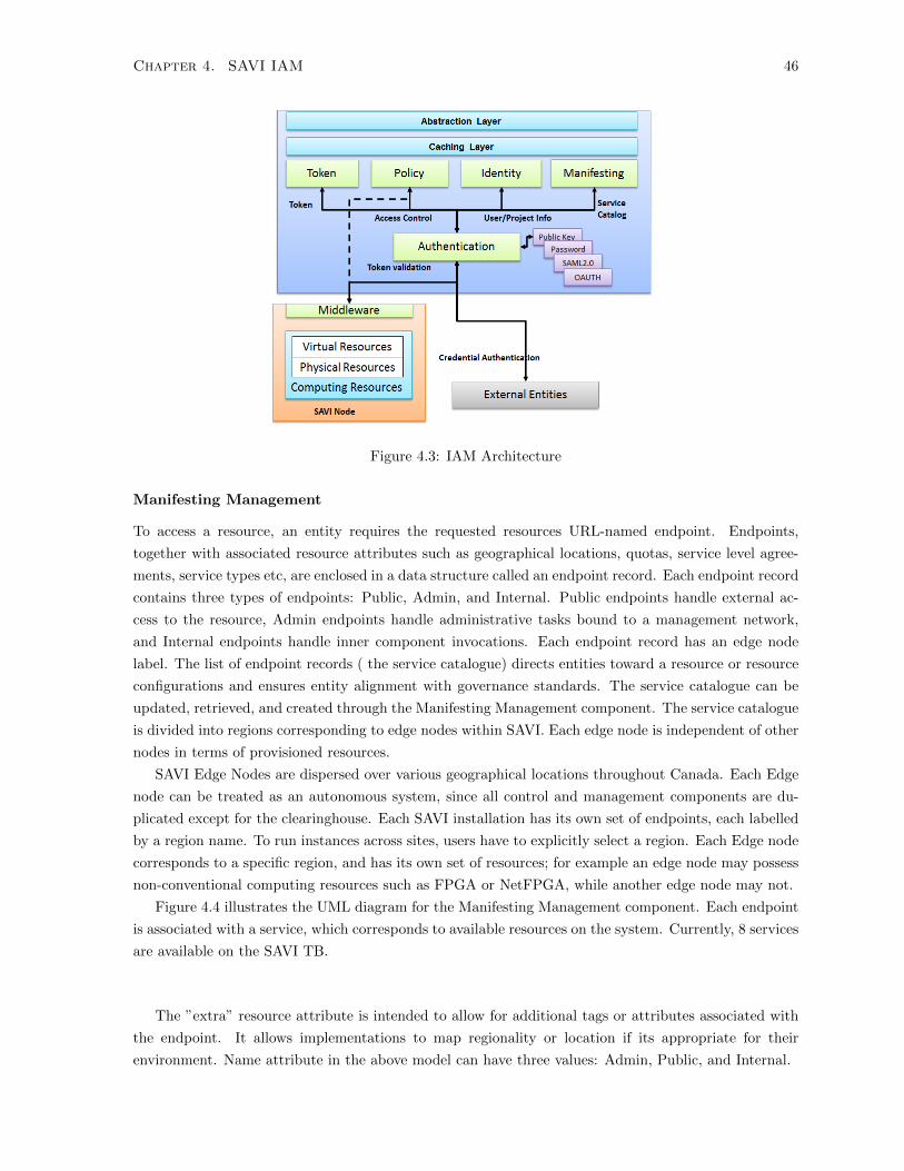
Chapter 4. SAVI IAM 46
Figure 4.3: IAM Architecture
Manifesting Management
To access a resource, an entity requires the requested resources URL-named endpoint. Endpoints,
together with associated resource attributes such as geographical locations, quotas, service level agree-
ments, service types etc, are enclosed in a data structure called an endpoint record. Each endpoint record
contains three types of endpoints: Public, Admin, and Internal. Public endpoints handle external ac-
cess to the resource, Admin endpoints handle administrative tasks bound to a management network,
and Internal endpoints handle inner component invocations. Each endpoint record has an edge node
label. The list of endpoint records ( the service catalogue) directs entities toward a resource or resource
configurations and ensures entity alignment with governance standards. The service catalogue can be
updated, retrieved, and created through the Manifesting Management component. The service catalogue
is divided into regions corresponding to edge nodes within SAVI. Each edge node is independent of other
nodes in terms of provisioned resources.
SAVI Edge Nodes are dispersed over various geographical locations throughout Canada. Each Edge
node can be treated as an autonomous system, since all control and management components are du-
plicated except for the clearinghouse. Each SAVI installation has its own set of endpoints, each labelled
by a region name. To run instances across sites, users have to explicitly select a region. Each Edge node
corresponds to a specific region, and has its own set of resources; for example an edge node may possess
non-conventional computing resources such as FPGA or NetFPGA, while another edge node may not.
Figure 4.4 illustrates the UML diagram for the Manifesting Management component. Each endpoint
is associated with a service, which corresponds to available resources on the system. Currently, 8 services
are available on the SAVI TB.
The ”extra” resource attribute is intended to allow for additional tags or attributes associated with
the endpoint. It allows implementations to map regionality or location if its appropriate for their
environment. Name attribute in the above model can have three values: Admin, Public, and Internal.

Chapter 4. SAVI IAM 47
Figure 4.4: Manifesting Management UML Diagram
Table 4.1: SAVI ResourcesService Name Service Type DescriptionNova Computation Provides virtual, bare metal, GPU, and atom machines.Swift Object Store Allocates storage to users and applications.IAM Identity Provides identity and access management.Quantum Networking Provides networking as a service between interface devices
(e.g. vNICs) managed by other SAVI services (e.g. Nova)Whale Configuration Provides testbed configuration, log, and topology information.Janus Management Provides a software-defined network manager.Cinder Volume Provides an infrastructure for managing volumes in the SAVI
testbed.Glance Image Provides services for discovering, registering, and retrieving
virtual machine images.
4.3.3 Identity Manager
The Identity Manager component is a central directory which stores users, projects, and relationship
information. When a user joins the SAVI testbed, their identity goes through the following lifecycle:
1. An entity is created for the user.
2. The administrator grants a role to a user entity within a project. If the requested project does not
exist, the administrator creates a new project.
3. The user sets their environmental variables, and sends a request for the desired resource.
4. When the task is complete, the user either manually revokes the toke or lets it expire.
Figure 4.5 shows the UML diagram for the identity component:
As Figure 4.5 illustrates,
• A user associated with no projects is useless from the perspective of SAVI testbed and should
not be authenticated for any resources. Users can be associated with one or more projects, and
therefore can also occupy one or more domains. A project id label on a user resource represents
a ’default’ project, which is used in authorization and validation calls. If no project id label is
provided for such calls, the user’s ”project id” is used as a default.

Chapter 4. SAVI IAM 48
Figure 4.5: Identity Management UML Diagram
• Credentials can have any format as long as they are serializable and associated with a user. How-
ever, a user can have multiple credentials. Type is a string attribute in the credential model is
that indicates how the blob should be interpreted, and can be ec2 and public key.
• Projects are the base units of ”ownership” in SAVI. Projects can have one or more users, but are
always associated with a single domain. Users are assigned to roles in the context of a project.
• Domains are collection of projects, which have their own standards, governance, and compliance.
4.3.4 Policy Management
The Policy Management component is a central repository for storing access policies. Administrators can
create, retrieve, update, and delete policies via this component. When the middleware wants to authorize
a request, it fetches access policies from the IAM by calling the Policy Management component. Each
access policy is associated with a service type, which enables administrators to define a separate policy
for each resource type. The Policy Management component has the following attributes:
• id
• endpoint id
• blob
• type
4.3.5 Token Management
The Token Management component is responsible for generating tokens for entities following the authen-
tication process, and associating tokens with security meta-data. For example, when the IAM receives

Chapter 4. SAVI IAM 49
an incoming list of users requesting access to a project, it extracts the users tokens and asks the Token
Management component to provide the necessary token authentication information. Token Management
component has the following attributes:
• id
• expires (iso8601 timestamp)
• user (full resource description, see User resource above)
• project (full resource description, see project resource above)
• catalogue (full description of all endpoints available to/for the token)
The Token Management component can generate two types of token formats:
• Universally Unique Identifier (UUID): The UUID is a series of letters and numbers to main-
tain the session of a user or application. When an entity sends a request with a UUID token, the
middleware connects to IAM to validate the token. The token management maintains the associ-
ated information with UUID tokens. For example, each token is associated with a project in which
the token is valid. To get the project from the token, the token management component needs to
be invoked. The token management component stores the project and the user of each token. If
other components need more than project and user id, they can invoke the identity management
component.
• Public Key Infrastructure (PKI): The IAM generates a PKI certificate for the entity and
signs it with its own Public Key; in this arrangement the authentication middleware does not need
to refer to the IAM to validate the token. PKI tokens enclose all information required to authorize
and authenticate a user. The IAM does not store any PKI token data.
4.3.6 Authentication Component
The Authentication component, when used in concert with the Token Management component, is the
cornerstone of the authentication process. The authentication module supports multiple authentication
mechanisms; it fetches a users attributes and project information via the identity module to validate
a users credentials. Separating logic from storage enables the IAM to support different authentication
methods independently of the Identity Management component, allowing for flexible authentication.
The IAM Authentication component determines the method of authentication in runtime. The following
snippet shows a typical authentication request:
As the above code shows an identity is a list of methods and corresponding data to authenticate the
identity with each method. For example, this request uses password based, token, and a custom plugin
authentication method to verify the identity of entities. It is possible to combine two or more methods
for the sake of strong authentication. For each method, the authentication component invokes the
appropriate plugin to authenticate the data, then aggregates the result of each plugin. There is a type of
authentication called re-scoping which means changing the security context. In re-scoping authentication,
entity does not want to authenticate itself, but it needs to change the associated information with a token.
For example, an entity needs to change the project to access another project files. If the authentication
is for re-scoping, entity must append the previous method names into ”method names”.

Chapter 4. SAVI IAM 50
Figure 4.6: An Authentication Request
Figure 4.7: IAM Middleware Architecture
For each credential authentication request, there is an identity-type field that defines the appropriate
method for validating the credential. Users can choose between different authentication methods (e.g.
Public Key, Password, OAUTH, or SAML v2.0) or even token formats.
4.3.7 Middleware
The middleware resides in front of a resource provider, allowing it to intercept requests. After a request is
authenticated and authorized, it is handed over to the service provider; otherwise, the request is directly
rejected. As shown in Figure 4.7, the proposed IAM incorporates two middlewares, for authentication
and authorization, respectively. The authentication middleware validates a token by sending it to the
IAM system, while the authorization middleware builds a security context from a request and maintains
a local version of access control policy synced with the IAM. To improve performance, authentication is
maintained within the IAM, while authorization is delegated to the resource provider.

Chapter 4. SAVI IAM 51
Figure 4.8: Openstack Keystone v2.0 Essex Architecture
4.4 Implementation
This section describes the detail of implementation for the SAVI IAM.
Openstack Keystone
SAVI IAM is built on top of Openstack Keystone V2.0 [ref]. Keystone is Openstack identity manager. It
has three basic components: Catalogue, Identity, and Token. Service catalogue stores a list of endpoints,
and identity backend verifies tokens and credentials and handle CRUD operations on users meta-data,
token backend generates tokens, and policy component manages policy operations. Keystone v2 does
not support policy CRUD operations and there is no PKI support at the moment. Figure 4.8, shows
the overall architecture of Keystone.
Keystone supports a well-defined format for credentials, and can generate tokens in Openstack and
EC2 format. Keystone has two kinds of APIs which serve different types of users: Administrative
operations can be performed through adminAPI; and regular queries go through Public API. It has an
authentication middleware that sits on in the front line of each resource on the cloud, this middleware
authenticate users tokens through Keystone. We choose Keystone v2.0 to build the SAVI IAM on top
of that because:
• SAVI testbed is based on Openstack. Therefore, Keystone v2.0 reduce the burden of developing
all Openstack identity APIs from beginning.
• The basic components (e.g. WSGI server, Paste, etc.) has already been implemented in Keystone
v2.0. It save the implementation time dramatically.
• Openstack Keystone v2.0 has an active community of development, therefore we can actively
receive a feedback about the SAVI IAM by comparing it with Openstack Keystone.
Access Control
Openstack Keystone has gone through 4 releases so far: Diablo, Essex, Folsom, and Grizzly. The SAVI
IAM is built on top of Essex version which has been released in 2012. In Essex version, access control
has been implemented very naively in which Keystone acts as a central directory. The access policy was
kept in local file systems in on resource providers. Because each service has a different interpretation for
each role, there has been a lot of inconsistency between privileges. For example, an admin role can list
objects in one resource, while in another resource, he may not. This access control model was used as a
foundation to develop the SAVI access management component.

Chapter 4. SAVI IAM 52
Figure 4.9: SAVI portal homepage
Web Portal
To provide a more intuitive interface to users, SAVI uses a Web UI portal based on Openstack Horizon.
Like other Openstack projects, Horizon is written in the Python programming language and uses a
Django web framework. Users can issue commands through either a Web UI portal or a command
line interface. In the proposed architecture, Openstack Horizon has been expanded to support central
Keystone. Consequently users can now easily switch between SAVI nodes and acquire or release their
resources. The main challenge in applying this expansion is in implementing region support in Openstack
clients such as Nova (Openstack computation component) clients, as the portal uses these clients to
interact with other Openstack components. The SAVI portal enables users to dynamically join, leave,
or create projects. The difference between a portal and a CLI is that users are able to issue the same
commands with fewer options through the web UI.
Figure 4.9 shows the homepage of the SAVI portal.
The side panel on the left enables users to interact visually with the Openstack components. Table
in Figure 4.9 shows the statistics of the infrastructure. To leave a project, the user clicks on the Project
Management.
Figure 4.10 shows a list of projects to which a user belongs. User can leave a project simply by
clicking on the Leave Project button. Projects can be joined or created in the same manner.
As Figure 4.11 shows, users can join available and publicly visible projects, or they can ask for a
new project. To switch between projects, users can click on the sidebar slider to choose the appropriate
project (Figure 4.12).
To switch between regions, users can simply click on the top rightmost menu (Figure 4.13).

Chapter 4. SAVI IAM 53
Figure 4.10: Project Management Page
Figure 4.11: Join Project Page

Chapter 4. SAVI IAM 54
Figure 4.12: Switch between projects
Figure 4.13: Switch between regions

Chapter 4. SAVI IAM 55
4.5 Conclusion
This chapter discusses about the proposed architecture for the IAM in the multi-tier cloud infrastructure.
The SAVI IAM distinguished itself from the works in the literature in terms of comprehensiveness,
practicality, and technology independence. The SAVI IAM addresses three classes of requirements for
the multi-tier cloud IAM: Identity Management, Access Control, and Scalability/Performance. The
SAVI IAM is composed of 6 basic components. Among these components, the middleware is located on
the resource provider. The middleware captures requests on the resource provider, and send them to
IAM for authentication. Authorization is performed on in the middleware itself. One of the advantages
of SAVI over previous works is flexibility in authentication. SAVI supports a wide range of authentication
methods in its authentication component, and in return, it generates both UUID and PKI token. The
SAVI IAM is built on top of Openstack Keystone v2.0 which is the identity manager for Openstack
infrastructure. Using Keystone saves the time of developing Openstack Identity APIs as the SAVI testbed
is using Openstack projects. Users of SAVI can interact with SAVI components through command-line
and web UI. In the next chapter, we focus on developing a fine-grained access control for SAVI.

Chapter 5
Access Control
5.1 Introduction
The core task of the IAM in the SAVI testbed is to control users and applications access to available
system resources. In security parlance, Access Control is the enforcement of a predefined access policy
on resources in order to confine the actions of an entity to only those requests and resources to which
it is entitled. The purpose of applying an Access Control policy is to reach a yes-no decision to accept
or reject a request to perform an action. Access Control should provide administrators a fine level
of control over access to their administrative domain. A fine-grained Access Control system provides
control over methods, resources, and collections of resources. If the enforcement point is incapable of
binding action requests to authenticated subjects with a sufficiently fine level of control, the access
policy can easily be subverted. Such binding is called Secure Association. In a safe access-control
policy, there is no access leakage to unauthorized users - directly or indirectly - at any level of the
underlying cloud system. Traditional Access Control mechanisms cannot satisfy the multi-tier cloud
infrastructure without modification. The multi-tier cloud infrastructure is more dynamic and distributed
than traditional systems, and security for such an environment poses unique challenges.
In the multi-tier cloud, users and applications occupy a variety of domains; therefore, the Access
Control system must cross the borders of administrative domains in order to function with heterogeneous
systems. In multi-tier clouds, both IAM services and resources should be protected from unauthorized
access. Therefore, the Access Control system for the cloud must enforce fine-grained access control at
both the function and object level to ensures that users with permission to call a function also have
appropriate access to target objects required to successfully perform a particular task. Access Control
needs more than an identity to make this decision, so the traditional identity-based access control
models - wherein entities and objects are managed via their identities - are insufficient. Such systems
are susceptible to such problems as role explosion and information leakage [37]. To overcome these
problems, the Access Control system should include the access context. In this application, Context is
defined as the sum of all characterizing information relevant to the implementation of Access Control,
including entity and resource attributes. Context enables Access Control to make an authorization
decisions based on specific attributes of the user and target object rather than their identities.
The most important concept in Access Control is Access Policy. A policy is a collection of assertions
that represent an entitys requirements, capabilities, preferences, and other properties that must be
56
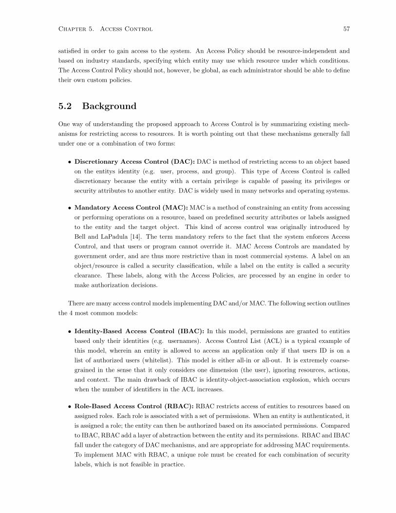
Chapter 5. Access Control 57
satisfied in order to gain access to the system. An Access Policy should be resource-independent and
based on industry standards, specifying which entity may use which resource under which conditions.
The Access Control Policy should not, however, be global, as each administrator should be able to define
their own custom policies.
5.2 Background
One way of understanding the proposed approach to Access Control is by summarizing existing mech-
anisms for restricting access to resources. It is worth pointing out that these mechanisms generally fall
under one or a combination of two forms:
• Discretionary Access Control (DAC): DAC is method of restricting access to an object based
on the entitys identity (e.g. user, process, and group). This type of Access Control is called
discretionary because the entity with a certain privilege is capable of passing its privileges or
security attributes to another entity. DAC is widely used in many networks and operating systems.
• Mandatory Access Control (MAC): MAC is a method of constraining an entity from accessing
or performing operations on a resource, based on predefined security attributes or labels assigned
to the entity and the target object. This kind of access control was originally introduced by
Bell and LaPadula [14]. The term mandatory refers to the fact that the system enforces Access
Control, and that users or program cannot override it. MAC Access Controls are mandated by
government order, and are thus more restrictive than in most commercial systems. A label on an
object/resource is called a security classification, while a label on the entity is called a security
clearance. These labels, along with the Access Policies, are processed by an engine in order to
make authorization decisions.
There are many access control models implementing DAC and/or MAC. The following section outlines
the 4 most common models:
• Identity-Based Access Control (IBAC): In this model, permissions are granted to entities
based only their identities (e.g. usernames). Access Control List (ACL) is a typical example of
this model, wherein an entity is allowed to access an application only if that users ID is on a
list of authorized users (whitelist). This model is either all-in or all-out. It is extremely coarse-
grained in the sense that it only considers one dimension (the user), ignoring resources, actions,
and context. The main drawback of IBAC is identity-object-association explosion, which occurs
when the number of identifiers in the ACL increases.
• Role-Based Access Control (RBAC): RBAC restricts access of entities to resources based on
assigned roles. Each role is associated with a set of permissions. When an entity is authenticated, it
is assigned a role; the entity can then be authorized based on its associated permissions. Compared
to IBAC, RBAC add a layer of abstraction between the entity and its permissions. RBAC and IBAC
fall under the category of DAC mechanisms, and are appropriate for addressing MAC requirements.
To implement MAC with RBAC, a unique role must be created for each combination of security
labels, which is not feasible in practice.

Chapter 5. Access Control 58
• Lattice-Based Access Control (LBAC): In LBAC, an ordered set of security labels is combined
with a set of categories to form a lattice. The lattice adds levels of indirection between security
labels and security classes. LBAC is effective when the system has a limited number of security
labels and categories. It provides a coarse-grained access control without scalability and flexibility.
• Attribute-Based Access Control (ABAC): In the ABAC model, all entity, resource, and
environmental attributes are considered in authorization decisions. The logic for decision-making
is written in a policy file. ABAC provides a flexible MAC mechanism in which administrators can
use all attributes (e.g. role, datetime, project etc.) to create a flexible authorization mechanism.
5.3 Requirement Analysis
In the section below, as in the previous chapter, the requirements for a SAVI testbed Access Control
system are outlined, followed with the proposed system design. In the previous chapter, an empty role
model was proposed for Access Management, in which the IAM stores only roles without permissions.
In other words, the IAM was the only Role Authority. Resources apply locally-stored policy files on the
entity roles in order to authorize each request. This chapter outlines the necessary Access Management
architecture to satisfy the following requirements:
• Central Policies Repository: A major design decision concerned where the access control
policies should be placed for use in access authorization. Traditionally, placing policies in a sep-
arate access authorization service was rejected for performance reasons. For simplicity, the same
approach outlined in the previous chapter was followed. Locally-stored policy files lead to incon-
sistency problem when a role is granted a permission in one resource, but it is granted the same
permission in another, similar resource.
• Least Privilege: The Access Control system should implement the least-privilege principle.
Least-privilege is an important principle in computer security, wherein an entity is required to
receive exactly the permissions it needs to perform its tasks. For example, most web servers do not
need to open connections to arbitrary addresses to order to perform their tasks. The absence of
this practice allows attackers to easily spread worms. Least privilege can protect the SAVI nodes
against accidental violations, Malware, and malicious applications.
• Explicit Trust: The intended Access Control system should provide flexible mechanisms to define
trust relationship, and delegate trust to another entity. One important aspect of trust relationships
is delegation of authority, in which an entity gives its attributes (e.g. role) for a specific duration
to another entity to perform a task. The delegation of the authority should be both flexible and
manageable in the sense that the authority should be allowed to delegate any subset of permissions
to subordinates, and the authority should have the capability of specifying what subordinates can
do.
• Separation of Duties (SoD): The Access Control system must support Separation of Duty, a
security principle used to distribute authority among multiple persons in order to complete a task.
The purpose of this principle is to prevent fraud by spreading the responsibilities and authorities
for an action.
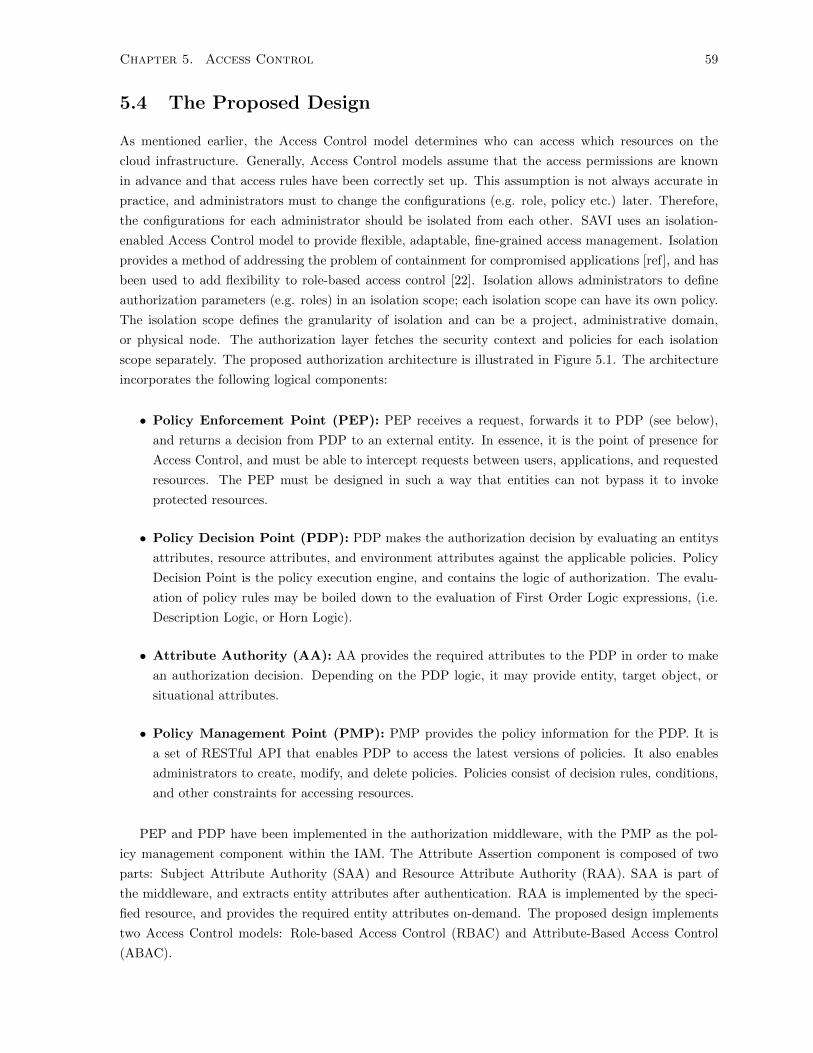
Chapter 5. Access Control 59
5.4 The Proposed Design
As mentioned earlier, the Access Control model determines who can access which resources on the
cloud infrastructure. Generally, Access Control models assume that the access permissions are known
in advance and that access rules have been correctly set up. This assumption is not always accurate in
practice, and administrators must to change the configurations (e.g. role, policy etc.) later. Therefore,
the configurations for each administrator should be isolated from each other. SAVI uses an isolation-
enabled Access Control model to provide flexible, adaptable, fine-grained access management. Isolation
provides a method of addressing the problem of containment for compromised applications [ref], and has
been used to add flexibility to role-based access control [22]. Isolation allows administrators to define
authorization parameters (e.g. roles) in an isolation scope; each isolation scope can have its own policy.
The isolation scope defines the granularity of isolation and can be a project, administrative domain,
or physical node. The authorization layer fetches the security context and policies for each isolation
scope separately. The proposed authorization architecture is illustrated in Figure 5.1. The architecture
incorporates the following logical components:
• Policy Enforcement Point (PEP): PEP receives a request, forwards it to PDP (see below),
and returns a decision from PDP to an external entity. In essence, it is the point of presence for
Access Control, and must be able to intercept requests between users, applications, and requested
resources. The PEP must be designed in such a way that entities can not bypass it to invoke
protected resources.
• Policy Decision Point (PDP): PDP makes the authorization decision by evaluating an entitys
attributes, resource attributes, and environment attributes against the applicable policies. Policy
Decision Point is the policy execution engine, and contains the logic of authorization. The evalu-
ation of policy rules may be boiled down to the evaluation of First Order Logic expressions, (i.e.
Description Logic, or Horn Logic).
• Attribute Authority (AA): AA provides the required attributes to the PDP in order to make
an authorization decision. Depending on the PDP logic, it may provide entity, target object, or
situational attributes.
• Policy Management Point (PMP): PMP provides the policy information for the PDP. It is
a set of RESTful API that enables PDP to access the latest versions of policies. It also enables
administrators to create, modify, and delete policies. Policies consist of decision rules, conditions,
and other constraints for accessing resources.
PEP and PDP have been implemented in the authorization middleware, with the PMP as the pol-
icy management component within the IAM. The Attribute Assertion component is composed of two
parts: Subject Attribute Authority (SAA) and Resource Attribute Authority (RAA). SAA is part of
the middleware, and extracts entity attributes after authentication. RAA is implemented by the speci-
fied resource, and provides the required entity attributes on-demand. The proposed design implements
two Access Control models: Role-based Access Control (RBAC) and Attribute-Based Access Control
(ABAC).

Chapter 5. Access Control 60
Figure 5.1: SAVI Authorization Architecture
5.4.1 Role-Based Access Control
Role-based Access Control (RBAC) is very useful Access Control model for cloud computing. Although
its benets are fundamentally limited to entity attributes, it simplies the management of permissions. The
main function of RBAC is the granting of permissions to users according to the assigned roles. Therefore,
roles furnish a layer of abstraction between users and permissions. Administrators assign roles to users,
and these roles incorporate new permissions as applications and systems join to them. There are three
operations in RBAC: role assignment, request authorization, and role-permission association. RBAC has
gone through the three main development stages - RBAC96, RBAC97, and RBAC02 - before becoming
industry standard.
• RBAC96: It is the based of implementation in SAVI. RBAC96 supports role-permission, role
hierarchy, and role constraints [61].
• Distributed RBAC (dRBAC): This system is not widely used; however, it is considered stan-
dard due to its being based on existing standard network protocols. dRBAC enables organizations
to implement their own RBAC system and issue certificates for their internal users to use the
organizations infrastructure. This certificate is signed by the home organizations public key, and
contains issuer, domain name, and user ID. The permissions and privileges of each role are confined
to the issuer domain (which is in the certificate) [18].
• RBAC02: In this system, users are not required to provide their identity to the resource provider;
instead, the service receives authorization from the policy engine. The user presents their identity
to the policy engine, receives authorizations, and presents these authorizations to the appropriate
service. RBAC02 has several advantages, including: easy delegation, simple system upgrades,
privacy preservation, and scalability [37].
Figure 5.2 illustrates the core RBAC model employed in SAVI testbed:
In Figure 5.2, each entity is assigned a role, which incorporates a set of permissions. Permissions
are a combination of actions and resources. For example, the combination of the action boot vm and a
computation resource constitute a permission. An administrator can assign permissions to roles in an
isolation scope. The SAVI RBAC is implemented at the API level. The required attributes to complete
authorization in SAVI RBAC are the list of user roles, user projects, and identity statuses. Authorization

Chapter 5. Access Control 61
Figure 5.2: Core RBAC Model
is performed by checking the attributes against the policy. SAVI accepts policy in JavaScript Object
Notation (JSON). The grammar for defining a policy is as follows:
"service/resource:action":[["role:role_name"]]
The service/resource can be a service or resource on the SAVI testbed or a component inside a re-
source. For example, a computation resource is composed of several components such as networking
management subcomponent. An administrator can define the policy at the resource level or the compo-
nent level. Action is an defined action inside the resource or component. Role is the policy predicate,
which allows an action to be performed on a resource if the role of an entity is equal to role name. This
model has been extended to accept project as predicate, as in the below example:
"compute_network:create_network":[["role:admin"], ["project: sample"]
This policy states that an entity can create a network in networking subcomponent of computation
resource if the role of entity is admin and the entity is a member of sample project. Although RBAC
provides two level of control (resource and component), it lacks flexibility in policy definition. Addition-
ally, there are three further drawbacks with RBAC: 1) substantial effort is required to define and assign
roles to users, 2) administrator must introduce new roles to cover discrepancies, leading to role-explosion
problems [38], and 3) RBAC is not suitable for cross-domain access management because reaching agree-
ment as to what permissions are associated with a role is difficult [10]. Due to these barriers and to
provide a finer level of access control, many service-oriented platforms have shifted to attribute based
access control.
5.4.2 Attribute-Based Access Control
Unlike RBAC, the Attribute-Based Access Control (ABAC) [71] model can grant permissions based on
security contexts known as attributes. An attribute is a named property or predicate of an entity (e.g.
role, project) that can be matched to a specific value. By considering role and identity as attributes of
an entity, ABAC combines the functions of both the IBAC and RBAC approaches. Therefore, ABAC
is the converged technology of all previous access control models, and surpasses them in functionality.
ABAC allows for semantically-richer and more expressive policy representation. As a result, it provides
flexible access management by providing a logic that is more discriminating and fine-grained. For Access
Control purposes, three main classes of attributes were considered:
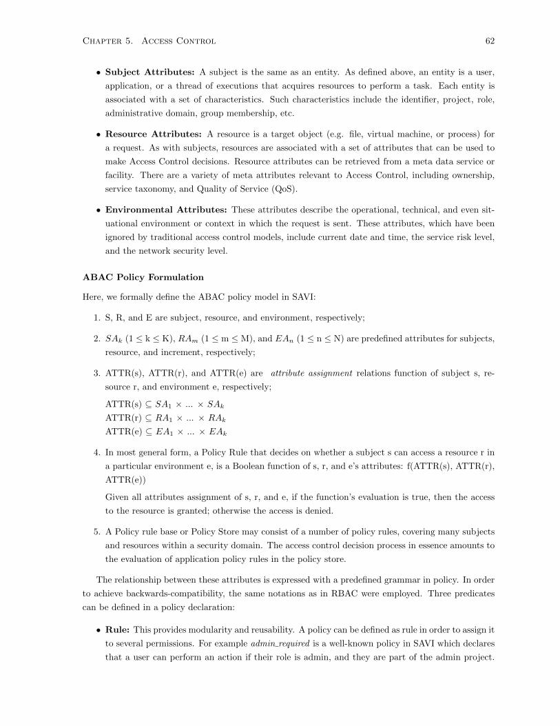
Chapter 5. Access Control 62
• Subject Attributes: A subject is the same as an entity. As defined above, an entity is a user,
application, or a thread of executions that acquires resources to perform a task. Each entity is
associated with a set of characteristics. Such characteristics include the identifier, project, role,
administrative domain, group membership, etc.
• Resource Attributes: A resource is a target object (e.g. file, virtual machine, or process) for
a request. As with subjects, resources are associated with a set of attributes that can be used to
make Access Control decisions. Resource attributes can be retrieved from a meta data service or
facility. There are a variety of meta attributes relevant to Access Control, including ownership,
service taxonomy, and Quality of Service (QoS).
• Environmental Attributes: These attributes describe the operational, technical, and even sit-
uational environment or context in which the request is sent. These attributes, which have been
ignored by traditional access control models, include current date and time, the service risk level,
and the network security level.
ABAC Policy Formulation
Here, we formally define the ABAC policy model in SAVI:
1. S, R, and E are subject, resource, and environment, respectively;
2. SAk (1 ≤ k ≤ K), RAm (1 ≤ m ≤ M), and EAn (1 ≤ n ≤ N) are predefined attributes for subjects,
resource, and increment, respectively;
3. ATTR(s), ATTR(r), and ATTR(e) are attribute assignment relations function of subject s, re-
source r, and environment e, respectively;
ATTR(s) ⊆ SA1 × ... × SAk
ATTR(r) ⊆ RA1 × ... × RAk
ATTR(e) ⊆ EA1 × ... × EAk
4. In most general form, a Policy Rule that decides on whether a subject s can access a resource r in
a particular environment e, is a Boolean function of s, r, and e’s attributes: f(ATTR(s), ATTR(r),
ATTR(e))
Given all attributes assignment of s, r, and e, if the function’s evaluation is true, then the access
to the resource is granted; otherwise the access is denied.
5. A Policy rule base or Policy Store may consist of a number of policy rules, covering many subjects
and resources within a security domain. The access control decision process in essence amounts to
the evaluation of application policy rules in the policy store.
The relationship between these attributes is expressed with a predefined grammar in policy. In order
to achieve backwards-compatibility, the same notations as in RBAC were employed. Three predicates
can be defined in a policy declaration:
• Rule: This provides modularity and reusability. A policy can be defined as rule in order to assign it
to several permissions. For example admin required is a well-known policy in SAVI which declares
that a user can perform an action if their role is admin, and they are part of the admin project.

Chapter 5. Access Control 63
This policy is used to protect administrative APIs. Because there are several administrative API,
instead of writing this policy multiple times, it can be defined as a rule.
• Security Context Attribute: Security context attributes contain the entity attributes. Security
context contains the entity ID, list of roles, project, and domain. These attributes are used in the
same manner as RBAC in the sense that role: admin means that the role of the entity should
posses an admin role. However, regular expression can be defined which means the value of an
attribute can be determined at the run-time. For example, a project:
• Field: Fields contain the set of object attributes. A policy can allow an action to be performed
if the target object has certain attributes. For example, a field:file:owner:public policy allows
actions to be performed on any public files. Field attributes grant policies the ability to make
authorization decisions based on the individual attributes of the target object. The advantage of
field operation is that it allows actions based on arguments of the called function. For example, to
connect a virtual machine to a virtual network, the virtual machine project can be retrieved using
”%(project)”. To retrieve the project of the virtual network, we can use ”Field:network:project”.
A sample policy for creating a virtual machine is as follows:
"compute: create-vm":[["rule:owner_required"]["rule:savi_admin_required"]]
"owner_required":[["role:admin"] and ["project:\%(project)"]]
Compute is the resource or a component in the resource, and create-vm is the name of action followed
by the policy.
The security context attributes are standard, and identical from one resource to another. However,
to keep the field definition flexible, the IAM allows each component to defines its own attributes inside
a data structure called a resource map. The Resource Map is dictionary that guides the authorization
middleware in extracting attributes. The authorization middleware can recognize a field so long as it
knows how to fetch the associated attributes and check them against policy. Attribute Authority uses
the resource map to extract attributes and provide them to the authorization middleware. The attribute
authority module varies from one resource to another, and is invoked by the authorization middleware
during access time. The second requirement for a newly introduced attribute is checker function, which
is called by the middleware to validate an attribute. The checker function directs the middleware in
interpreting an attribute. The middleware passes the value of the attribute along with the policy as an
argument to the checker, and the function returns a Boolean value to indicate approval or denial.
The middleware can apply policies for two reasons: to protect a function, or filter its output. When
policy is applied to protect a function, it intercepts a request before calling the function. If the request
is authorized, the middleware calls the function on its behalf; otherwise, it is denied by the middleware.
Protection can be considered as a binary function that either accepts or denies a request. When applied
to filtering, policy removes the unauthorized output of a function. To filter the output, the middleware
calls the function and removes unauthorized attributes of the returned values. Policy parsing is a time-
consuming and complex job, involving the use of a greedy reduction algorithm to reduce a sequence of
tokens into a single terminal. The value of this terminal forms the root of the Decision making tree,
wherein each token maps to a checker function.

Chapter 5. Access Control 64
5.4.3 Delegation and Trust
Delegation of duty allows a task to be performed even when the initially-assigned user is not available.
This is accomplished by granting an entity (user or process) the ability to perform an action temporarily.
Delegation is useful when an administrator wishes to authorize an application or user at setup time to
perform errands in the future, long after a token is expired. There are two types of delegation:
• Dynamic Delegation of Authority (DelAuth): DelAuth grants all or part of a users authority
(delegator) to another user (delegatee) to perform a task.
• Dynamic Delegation of Action (DelAct): DelAct grants a user the required permissions
because the request is part of an authorized process.
There are three main situations where a delegation is required:
• Role Backup: When the authority is not available to complete a task, an administrator can
delegate privileges to another entity to perform the task on the first entitys behalf. The Failover
application is an example of applications that need delegation of authority to recover the system
on behalf of administrator when they are unavailable.
• Decentralization of authority: Delegation helps distribute functions in a group, satisfying the
separation-of-duties principle.
• Collaboration of works: When two parties work on the same resource for a period of time, both
must be granted access to that resource.
The SAVI IAM supports the Permission-based Delegation Model (PBDM) [74], an RBAC96-based
model. In this system, a user can delegate privileges by delegating a role associated with a permission
to one or more other users and confining that permission to a project. There are two types of roles
in SAVI: regular roles and delegation roles. When a user delegates a permission, a delegation role
associated with the permission is created and assigned to another user. In SAVI, the unit of delegation
is the permission that corresponds to a delegation role. Users can also assign regular roles, which contain
a set of permissions. Administrators can delegate roles and permissions by default, but members require
explicit authorization to delegate their roles. Delegation roles are created by administrators; therefore,
administrators can control the permission flow by mapping permissions to delegations roles.
As delegation is a temporary privilege granted to an entity. Entities can obtain a delegation role
during the access time once they have been authenticated. Delegation is an internal IAM process, isolated
from protected services and middleware. This isolation it is useful when an administrator wishes to set
up automated tasks. For example, when an application needs to scale up, the administrator can issue
a delegation which authorizes the application to create more virtual instances of itself. In SAVI, a
delegation privilege is a combination of project and delegated roles. An entity can be granted roles
only within the scope of a designated project, and users cannot delegate whole roles to other users.
Administrators can define more conditions for delegation (such as endpoints) to which an application can
send requests. Delegated permissions can be recursively delegated to another user through a delegation
chain.

Chapter 5. Access Control 65
5.5 Conclusion
Access Control decisions play an important role in any system that implements a multi-tenancy model.
For cloud computing - a large scale-implementation of a shared model - access decisions must be more
flexible and scalable than in standard models. This chapter defined the requirements for achieving fine-
grained access control in a multi-tier cloud, and detailed the features of different access control models.
A proposed design was outlined for an access model diagnostic authorization architecture, which imple-
ments two popular access models: RBAC and ABAC. At the end of the chapter, the function of delegation
and trust in SAVI was described. Delegation and trust are essential features in application-oriented in-
frastructure, allowing applications to perform tasks on behalf of different users. The advantages of SAVI
access management are threefold. First, it is independent of the specific Logic implemented; second,
it provides authorization for any fine level of control; and finally, it supports delegation of authority
to applications wherein an administrator can give a permission to an application at some point in the
future.

Chapter 6
Performance and Scalability
6.1 Introduction
The multi-tier cloud infrastructure must be capable of scaling to accommodate billions of transactions
for millions of users and application identities. In such infrastructures, a bottleneck occurs at the
identity manager. If the IAM slows down, the effect cascades to other resource providers in the cloud.
According to the Open Cloud Manifesto, a cloud infrastructure should dynamically scale itself so no single
entity can hoard resources during peak hours. CRUD (Create, Retrieve, Update, Delete) operations,
flexible authentication, and attribute-based authorization features in previous chapters degrade system
performance, preventing the SAVI IAM from operating in a product-level environment. To prepare the
system for installation in the SAVI testbed, performance must be boosted and the system made scalable
in order to handle large request volumes without serious performance degradation.
The central issue concerning the scalability of the IAM is the systems ability to support both growing
numbers of concurrent requests and different operation types. The following section focuses on impor-
tant design considerations required to support scalability in different contexts. The most important
consideration is the fact that the overall number of entities being concurrently used is not predictable
and varies over time. It is therefore proposed to use a loosely coupled network of IAM instances with
a standardized load balancer in the front end and coherent caching layer on the back end. Since each
IAM instance manages a collection of requests, the load balancer serves to distribute requests among
the various instances. Thus, two requests from the same user can be served by different instances. To
enable the IAM instances to serve each others requests, each requests security data is decoupled from
the serving instance. An instance can thus control the workload in a manageable manner in a similar
manner to the middle-tier within a multi-tier client-server architecture.
6.2 Requirement Analysis
To better understand the requirements for achieving scalability, it is necessary to examine the relation-
ship between architectural decisions and scalability issues. Only then can strategies for improving the
scalability and performance of IAM be determined.
66
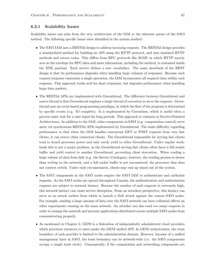
Chapter 6. Performance and Scalability 67
6.2.1 Scalability Issues
Scalability issues can arise from the very architecture of the IAM or the inherent nature of the SAVI
testbed. The following specific issues were identified in the system studied:
• The SAVI IAM uses a RESTful design to address incoming requests. The RESTful design provides
a standardized method for building an API using the HTTP protocol, and uses standard HTTP
methods and return codes. This differs from RPC protocols like SOAP, in which HTTP merely
acts as the envelope for RPC data and most information, including the method, is contained inside
the XML payload. Each service defines a new vocabulary. The main drawback of the REST
design is that its performance degrades when handling large volumes of responses. Because each
request/response represents a single operation, the IAM incorporates all required data within each
response. This approach works well for short responses, but degrades performance when handling
large data packets.
• The RESTful APIs are implemented with Greenthread. The difference between Greenthread and
native thread is that Greenthread employs a single thread of execution to serve the requests. Green-
thread uses an event-based programming paradigm, in which the flow of the program is determined
by specific events (e.g. IO complete). It is implemented by Coroutines, which is useful when a
process must wait for a user input for long periods. This approach is common in Service-Oriented
Architectures. In addition to the IAM, other components in SAVI (e.g. computation control) serve
users via synchronous RESTful APIs implemented by Greenthread. The main difficulty regarding
performance is that when the IAM handles concurrent GET or POST requests from very fast
clients, it can starve other connected clients. The Greenthread responsible for serving fast clients
tend to hoard processor power and only rarely yield to other Greenthread. Under regular work-
loads this is not a major problem, as the Greenthread serving fast clients often faces a full socket
buffer and yield control to another Greenthread, preventing client starvation. When reading a
large volume of data from disk (e.g. the Service Catalogue), however, the reading process is slower
than writing to the network, and a full socket buffer is not encountered; the processor thus does
not context switch. Under such circumstances, clients may end up timed out of the system.
• The SAVI components in the SAVI nodes require the SAVI IAM to authenticate and authorize
requests. As the SAVI nodes are spread throughout Canada, the authentication and authorization
requests are subject to network latency. Because the number of such requests is extremely high,
this network latency can cause service disruption. From an attackers perspective, this latency can
serve as an attack surface from which to launch a DoS attack against the remote SAVI nodes.
For example, sending a large amount of data over the SAVI network can have collateral effects on
other experiments running on the same network. An attacker can also send too many requests in
order to swamp the network and prevent applications distributed across multiple SAVI nodes from
communicating properly.
• As mentioned in Chapter 2, GENI is a federation of independently administered cloud providers
which provision resources to users under the GENI unified API. In GENI orchestration, the trust
boundary of each provider is limited to the administration domain. However, because of a unified
management layer in SAVI, the trust boundary can be network-wide (i.e. the SAVI components
occupy a single trust circle). Consequently, if the computation and networking components are
Chapter 6. Performance and Scalability 68
authenticated to the SAVI testbed, the computation does not need to authenticate the network for
each request. To enhance security, request authentication has traditionally been a built-in feature
within the SAVI testbed. In the proposed IAM design, however, internal authentication between
the SAVI components is no longer required due to the unified management layer.
6.2.2 Scalability Strategies
The most important scalability concern encountered during the design phase was the distribution of
functions between the IAM and the resources providers, as both authentication and authorization are
time-consuming and resource-intensive jobs. Consequently, authorization was delegated to middleware
on the resource provider, while we maintained the authentication in the centralized IAM. This has the
following advantages:
• By keeping authentication in the IAM, the users privacy is preserved.
• Because authorization policies are rarely changed, they can be locally cached on the resource
provider.
• The authorization logic is lighter in terms of implementation, making the middleware source code
more efficient.
• Because authorization is dependent on the resources attributes as well, certain aspects should be
implemented by the resource provider.
As mentioned earlier, a slow central IAM can inflict delays on the whole testbed operation. Therefore,
a scalable IAM should be capable of returning responses in a reasonable time, and coping with a large
volume of requests without considerable throughput reduction. Among IAM functions, token authen-
tication is the most frequent operation, followed by credential authentication. Policy management is a
comparatively fairly rare operation. User, tenant, and role-membership are conducted at roughly similar
rates, but still less frequently than authentication. Finally, authorization of resources is performed, and
is therefore irrelevant to the operation of the IAM.
Two strategies were implemented to boost performance and make the IAM scalable:
1. Optimizing IAM response time and increasing throughput
2. Decreasing the number of calls to the IAM
Optimization is useful for handling requests which take a long time to respond, such as data querying
and formatting. Table 6.2.2 tabulates average response size with likelihood of occurrence. The logs of
the operational IAM were collected for a duration of two weeks, and the response sizes measured and
averaged. The last column shows the contribution of each operation to the generated traffic by the
IAM. The likelihood of occurrence is driven by dividing the number of calls for an operation by the total
number of calls.
The response time is proportional to the generated traffic as all the data should be retrieved from
the data store and formatted. Although policy management requires greater packet sizes than authenti-
cation, due to its rarer occurrence the generated traffic is fairly low. Therefore, any optimization of the
authentication operation can considerably increase overall performance.

Chapter 6. Performance and Scalability 69
Table 6.1: SAVI IAM functions trafficOperation Likelihood Response size Average TrafficAuthentication 0.76 200KB 152 KBhline Policy Management 0.001 250KB 0.25KBhline User, Role, Project CRUD 0.1 10KB 1KB
Figure 6.1: Single Process IAM
Two processes are required to build a response to an authentication request: the retrieval of credential
info and the formatting of the service catalogue. The service catalogue is a large chunk of data, as it lists
all available resources and associated attributes on the cloud. Since the service catalogue is dependent
on user information (e.g. Project ID), it must be separately formatted for each request. The service
catalogue cannot be partitioned because it is required in its entirety by the user. The formatted data,
however, can be cached for each individual user. In the proposed design, a caching layer is implemented
to take over this responsibility.
To decrease the number of calls to the IAM, some data must be cached in the middleware. An
examination of the authentication middleware workflow reveals that it is not necessary to authenticate
each token for every incoming IAM request, as the tokens remain valid for a long period of time.
Instead, it is possible to update the validity status of a series of tokens. This authentication must be
cache-coherent, meaning it should be performed locally without violating the semantics of the operation.
Using these strategies as a guideline, an architecture was developed employing middleware caching and
offline token validation to boost performance. We have implemented the IAM with Greenthread to
conserve the system resources. To enhance the scalability, we create several instance of the IAM process,
and do load balancing over them. Each instance of IAM is a Greenthread to conserve the system
resources (e.g., Memory and Processing).
6.3 Proposed Design
The SAVI IAM follows a Model-View-Controller (MVC) architecture. MVC divides the IAM into three
basic layers. The View Layer is the REST API that users and applications receive services from.
The Controller Layer is logic of the IAM; authentication, policy management, and user management are
examples of typical logics. The Model Layer permanently stores applications, abstracting the underlying
storage system (e.g. SQL DB, LDAP, etc.). Figure 6.1 illustrates the MVC architecture for each IAM
component:
The Abstraction Layer is a an abstract class that loads the appropriate drivers and corresponding
configurations during the run-time. When a request arrives, the REST determines the proper controller

Chapter 6. Performance and Scalability 70
Figure 6.2: Multi-instances IAM
to call by analyzing the URL in the header. The controller then receives the request and, after processing
the body, retrieves the data from the Model Layer to build the response. The Model Layer is an Object-
Relational Mapping (ORM) that converts the raw data to objects before sending it to the controller.
All these components can run within a single process in the system. Each process has one Greenthread
to use the system resources efficiently. Each process is referred to as an IAM instance. The proposed
architecture is composed of multiple instances of IAM, and a load balancer to distribute requests among
the instances.
As shown in Figure 6.2, the load balancer distributes requests from both the middleware and di-
rectly from users among the IAM instances. The IAM instances have a caching layer to cache security
information (e.g. the Service Catalogue), or share sensitive information (e.g. token data). These layers
return the response directly to the client or middleware in order to decrease the load of the load bal-
ancer. The middleware also has a local cache to cache user data - including tokens. This architecture
solves the problem of handling large data volumes by deploying multiple instances of the IAM. When
an instance is busy, the load balancer sends the request to another instance. Furthermore, because the
requests are distributed uniformly, they do not accumulated on one instance and cause timeout issues.
The Caching Layer reduces response time by saving formatting and query data for each instance. The
middleware is also capable of storing data in the local cache, which improves provider performance since
the middleware does not need to contact the IAM for the consecutive requests from the same entity. This
also decreases the traffic through the SAVI network, as resource providers need the IAM to periodically
update their local caches. The remainder of this section outlines the challenges encountered in designing
and implementing the architecture shown in Figure 6.2.
6.3.1 Caching Layer
The Caching layer is effective at improving SAVI IAM performance, and can also improve resource
provider responsiveness. For the data cache, a major consideration is what data in the IAM should
be cached and how this data should be cached. The main design features of the Caching Layer are as
follows:
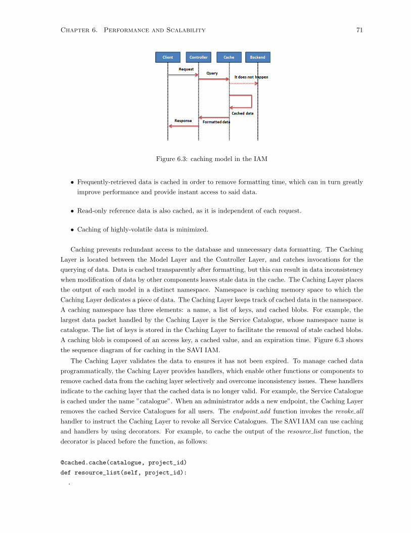
Chapter 6. Performance and Scalability 71
Figure 6.3: caching model in the IAM
• Frequently-retrieved data is cached in order to remove formatting time, which can in turn greatly
improve performance and provide instant access to said data.
• Read-only reference data is also cached, as it is independent of each request.
• Caching of highly-volatile data is minimized.
Caching prevents redundant access to the database and unnecessary data formatting. The Caching
Layer is located between the Model Layer and the Controller Layer, and catches invocations for the
querying of data. Data is cached transparently after formatting, but this can result in data inconsistency
when modification of data by other components leaves stale data in the cache. The Caching Layer places
the output of each model in a distinct namespace. Namespace is caching memory space to which the
Caching Layer dedicates a piece of data. The Caching Layer keeps track of cached data in the namespace.
A caching namespace has three elements: a name, a list of keys, and cached blobs. For example, the
largest data packet handled by the Caching Layer is the Service Catalogue, whose namespace name is
catalogue. The list of keys is stored in the Caching Layer to facilitate the removal of stale cached blobs.
A caching blob is composed of an access key, a cached value, and an expiration time. Figure 6.3 shows
the sequence diagram of for caching in the SAVI IAM.
The Caching Layer validates the data to ensures it has not been expired. To manage cached data
programmatically, the Caching Layer provides handlers, which enable other functions or components to
remove cached data from the caching layer selectively and overcome inconsistency issues. These handlers
indicate to the caching layer that the cached data is no longer valid. For example, the Service Catalogue
is cached under the name ”catalogue”. When an administrator adds a new endpoint, the Caching Layer
removes the cached Service Catalogues for all users. The endpoint add function invokes the revoke all
handler to instruct the Caching Layer to revoke all Service Catalogues. The SAVI IAM can use caching
and handlers by using decorators. For example, to cache the output of the resource list function, the
decorator is placed before the function, as follows:
@cached.cache(catalogue, project_id)
def resource_list(self, project_id):
.
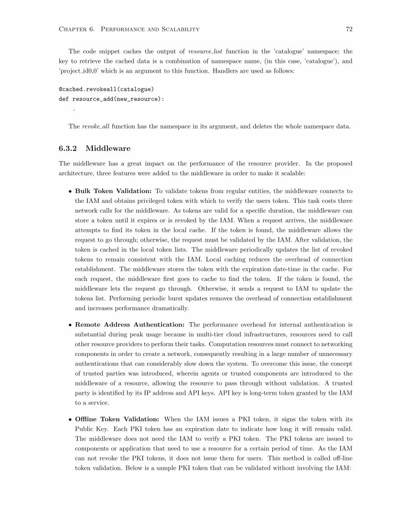
Chapter 6. Performance and Scalability 72
The code snippet caches the output of resource list function in the ’catalogue’ namespace; the
key to retrieve the cached data is a combination of namespace name, (in this case, ’catalogue’), and
’project id0,0’ which is an argument to this function. Handlers are used as follows:
@cached.revokeall(catalogue)
def resource_add(new_resource):
.
The revoke all function has the namespace in its argument, and deletes the whole namespace data.
6.3.2 Middleware
The middleware has a great impact on the performance of the resource provider. In the proposed
architecture, three features were added to the middleware in order to make it scalable:
• Bulk Token Validation: To validate tokens from regular entities, the middleware connects to
the IAM and obtains privileged token with which to verify the users token. This task costs three
network calls for the middleware. As tokens are valid for a specific duration, the middleware can
store a token until it expires or is revoked by the IAM. When a request arrives, the middleware
attempts to find its token in the local cache. If the token is found, the middleware allows the
request to go through; otherwise, the request must be validated by the IAM. After validation, the
token is cached in the local token lists. The middleware periodically updates the list of revoked
tokens to remain consistent with the IAM. Local caching reduces the overhead of connection
establishment. The middleware stores the token with the expiration date-time in the cache. For
each request, the middleware first goes to cache to find the token. If the token is found, the
middleware lets the request go through. Otherwise, it sends a request to IAM to update the
tokens list. Performing periodic burst updates removes the overhead of connection establishment
and increases performance dramatically.
• Remote Address Authentication: The performance overhead for internal authentication is
substantial during peak usage because in multi-tier cloud infrastructures, resources need to call
other resource providers to perform their tasks. Computation resources must connect to networking
components in order to create a network, consequently resulting in a large number of unnecessary
authentications that can considerably slow down the system. To overcome this issue, the concept
of trusted parties was introduced, wherein agents or trusted components are introduced to the
middleware of a resource, allowing the resource to pass through without validation. A trusted
party is identified by its IP address and API keys. API key is long-term token granted by the IAM
to a service.
• Offline Token Validation: When the IAM issues a PKI token, it signs the token with its
Public Key. Each PKI token has an expiration date to indicate how long it will remain valid.
The middleware does not need the IAM to verify a PKI token. The PKI tokens are issued to
components or application that need to use a resource for a certain period of time. As the IAM
can not revoke the PKI tokens, it does not issue them for users. This method is called off-line
token validation. Below is a sample PKI token that can be validated without involving the IAM:
Chapter 6. Performance and Scalability 73
Figure 6.4: Load balancing over the IAM instances
{"auth":{"identity":"pki", "credential":{"username":"Bob","project":"demo",
"expires":"05092013","roles":["admin","saviAdmin"]}}
Because most tokens are from regular entities, they are valid for long periods of time; in the short
term, however, they can be cached in the middleware. Meanwhile, internal components are already
within the trust circle, and do not need authentication.
6.3.3 Load balancing
It is required that the SAVI IAM maintain the same performance level even when the number of users
is increased dramatically. In the proposed architecture, load balancing is used to disperse requests
between IAM instances. However, different data processes do not have access to each others memory
space; consequently, they may be unable to find request states (such as tokens), causing entities to
receive constant Unauthorized errors. To deal with this issue, IAM places tokens and security data
on memcache under the same namespace. Through a system-wide caching layer, different instances can
access security information by leveraging namespace and encryption parameters in order to secure cached
data. A load balancer uniformly distributes requests among the instances, and creates more instances
when the number of requests for each instance exceeds a certain threshold. As a result, the IAM system
is able to dynamically scale itself by increasing the number of backend processes.
Figure 6.4 shows the workflow for a load-balanced IAM. A request enters the load balancer and is
served by one of the Event-based processes. The load balancer forwards requests to one of the IAM
processes (EP1 to EPn). The IAM keeps the state out of each process memory so that other event-based
processes can access it. There is a memcache layer on the back of each process which stores the states
of requests so that processes can serve each others requests.
6.4 Performance Evaluation
In this section, the performance of the proposed IAM using the SAVI Testbed is evaluated. The equip-
ment setup will first be described, followed by results of the experiment.

Chapter 6. Performance and Scalability 74
6.4.1 Apache JMeter
Apache JMeter is an open-source Java desktop application designed to carry out performance analysis on
a variety of applications, including HTTP(S), SOAP (Simple Object Access Protocol), JMS, JDBC (Java
Database Connectivity), LDAP (Lightweight Directory Access Protocol), POP3 (Post Office Protocol),
and IMAP (Internet Message Access Protocol). It performs load and robustness testing to analyze and
measure the functional behavior of an application under different load types. JMeter has a decent UI, but
can also be run from the command line if necessary. As JMeter runs on a Java Virtual machine, it can
be run on a variety of operating systems and has native support for multithreading (i.e. scenarios where
simulating concurrent users is desired). It has a fully configurable, pluggable, and scriptable (e.g. using
BeanShell1) test architecture, so all types of performance tests can be run with it. In addition, multiple
test iterations (runs), input parameterization, loops, assertions and timers are supported out-of-the-box.
Thread groups are used to specify the number of running threads and the ramp-up period. Each
thread simulates a concurrent user, and the ramp-up period specifies the time required to create all the
threads. For example with 5 threads and 5 seconds of ramp-up time, a thread is created every second.
The loop count defines the running time for a thread. The scheduler also allows the start and end of the
run time to be specified.
Pluggable samplers allow for a number of metrics to be recorded at test run-time. Basic test data
analysis and reporting facilities are also included; these can be extended by installing appropriate plug-
ins. JMeter uses a proprietary XML format to store both test plans (steps) and test result data.
RESTFUL can be tested in JMeter using the ”RestSampler” sampler.
Listeners are used to post-process request data. For example, data can be saved to a file or be
displayed using a chart. At the moment, the JMeter chart does not provide many configuration options;
however, it is extensible. It is thus always possible to add an extra visualization or Graph result listener
to allow result to be viewed as a graph; for example, the Spline Visualizer listener allows the result to
be displayed as a smooth curve.
Experimental Setup To run these SAVI IAM, we used a XEON machine on SAVI testbed. Table
6.4.1 shows the system of characteristics of the machine running IAM:
Table 6.2: SAVI IAM System CharacteristicsNumber of Processors 12Memory 32GBOperating Systems Ubuntu64JDK Oracle 7Python 2.7
To evaluate the performance, we conducted a distributed testing on IAM because a single client
machine is unable, performance-wise, to simulate enough users to stress IAM. Therefore a master machine
can control multiple, remote JMeter engines from a single JMeter GUI client. Each engine is an Xeon
system with 4 processors 4 GB memory on SAVI. The master is a large virtual machine with 4 processors
and 8 GB memory. To configure distributed testing, a JMeter server should be running on each slave,
and a GUI client on master machine. To run JMeter server in remote node, start the JMeter server
component on all slaves by running the apache-jmeter/bin/jmeter-server. Now, the properties file on
the controlling JMeter machine should be edited so it has the remote slaves. In /bin/jmeter.properties,
Chapter 6. Performance and Scalability 75
in front of property, ”remote hosts”, and list of remote slaves must be added. Multiple such slaves can
be added via comma-delimited.
6.4.2 SAVI IAM Setup
To install SAVI IAM on Ubuntu 12.04, the system should have the following tools:
• Python 2.7
• git
• setuptools (Python library)
• pip
To install these tools run the following command in terminal:
# sudo apt-get install git-core python-pip
# sudo pip install setuptools
Then we make a clone of the code from the repository
# git clone https://github.com/mfaraji/keystone
# cd keystone
# git checkout -b silver remotes/origin/silver
Then we need to install dependencies:
# sudo apt-get install python-dev libxml2-dev libxslt1-dev libsasl2-dev libmysqld-dev
# sudo pip install -r tools/pip-requires
In our setup, we use mysql and memcached as our backend. Thus, we need to install these backends
as well:
# sudo apt-get install mysql-server memcached
We are using haproxy for load balancing the load between IAM instances. To install haproxy:
# sudo apt-get install haproxy
To activate haproxy, we need to add it to system services:
# sudo vim /etc/default/haproxy
Then change ENABLED from 0 to 1. Then restart the service:
# sudo service haproxy restart
In the load balancer experiment, we explain how to configure load balancer to work with IAM
instances. Now, we addresses all requirements to run SAVI IAM on our system. Now, we need to
configure the backends:

Chapter 6. Performance and Scalability 76
1. Create keystone config folder:
# sudo mkdir /etc/keystone
2. Copy configuration the following configuration files from keystone folder to /etc/keystone folder:
• keystone.conf
• logging.conf
• policy.json
3. Now configure database credentials:
# sudo vim /etc/keystone/keystone.conf
4. If memcache is not on the same machine, we need to modify the address and port in keystone.conf
To create the corresponding tables, we need to create to database first:
# mysql -u<username> -p<password>
mysql> create database keystone
To create tables: navigate to the root of the keystone folder, and run:
# bin/keystone-manage --config-file /etc/keystone/keystone.conf db_sync
To run the service:
# bin/keystone-all --config-file /etc/keystone/keystone.conf --debug
To interact with the SAVI IAM, Keystone client should be installed. To install Keystone client:
# git clone https://github.com/m/python-keystoneclient
# cd keystone
# git checkout -b silver remotes/origin/silver
The navigate to the repository to install the client:
# cd python-keystoneclient
# sudo python setup.py install
Next, the environment variables should be set. To set the variables, run the following commands:
# export OS_USERNAME=<user-name>
# export OS_TENANT_NAME=<tenant-name>
# export OS_REGION_NAME=<region-name>
# export OS_PASSWORD=<password>
# export OS_AUTH_URL=<url-to-openstack-identity>

Chapter 6. Performance and Scalability 77
(run ”env — grep OS” command to make sure values are set correctly) he first argument is username,
the second is tenant, the third is name of region, and the last is the URL of Keystone. At the end the
following environment variables need to be set properly before any interaction with SAVI TB.
The region parameter is the name of the SAVI TB name. For now, it could be any of the following
nodes: CORE (UofT), EDGE-TR-1 (Edge at UofT), EDGE-WT-1 (Edge at UWaterloo), EDGE-MG-1
(Edge at McGill). By choosing this parameter, you can specify on what Edge/Core node you want to
get resource.
Now run the following command to see the list of endpoints:
# keystone endpoint-list
6.4.3 Test Scenarios
This section explains the different experimental scenarios used during testing and the specific metrics
measured. In these test scenarios, the following parameters were measured in each authentication oper-
ation:
• Throughput: the number of requests processed per minute by the IAM or middleware.
• Average: the total running time divided by number of requests sent to the IAM or Middleware.
• Median: the component response time value where half of the response times are lower and half
are higher.
• Deviation: the measure of how widely the component response time varies i.e. how dispersed the
data is.
Evaluations were performed on three different systems:
1. The baseline system (Keystone v2.0. 2), against which the proposed system was compared.
2. A single instance of the SAVI IAM with Caching-Layer enabled 3).
3. A multi-instance, full-featured SAVI IAM (Caching-Layer enabled) .
In all experiments, the system was divided into 300 projects and 10 regions (SAVI nodes); each
region contains 10 endpoints for a total of 100 endpoints. The system performance is measured while
the number of concurrent fast clients is varied from 1 to 256. Fast clients are dumb processes which do
not process responses, but continuously send requests to the SAVI IAM.
Figure 6.5 shows the experimental results for the baseline (Keystone v2.0) system. As can be seen,
system performance degrades significantly as the number of users increases. This is seen as a rapid
degradation of throughput (measured in requests served per second) on right-hand y-axis, and a large
increase in response time (measured in milliseconds) on the x-axis. When the number of concurrent fast
clients passes 128, the number of successful requests decreases sharply due to user timeout.
As shown in Figure 6.5, request response time increases with the number of concurrent users. The
response times are concentrated around the average values, and are independent of the total number of
the requests. This results from all requests being treated identically due to the lack of caching in the
tested system.

Chapter 6. Performance and Scalability 78
Figure 6.5: Openstack Keystone v2.0
Figure 6.6: Single Process IAM

Chapter 6. Performance and Scalability 79
Figure 6.7: Full-featured IAM
Figure 6.6 shows the experimental results for a single-instance implementation of SAVI IAM with
Caching-Layer enabled. As described before, the Caching Layer performs transparent caching of data for
request responses. As shown in Figure 6, the response time begins to vary once the number of concurrent
requests passes 32 due to request repetition. Despite the caching, timeout occurs when the concurrent
request volume reaches 256 - just as with the baseline Keystone v2.0 system. The throughput of the SAVI
IAM, however, is higher than the baseline system at high concurrent-user volumes. At lower volumes,
Keystone v2.0 slightly outperforms SAVI IAM since SAVI IAM places a version of each response in a
cache as well. As the number of requests increases, the caching boosts the throughput because there is
no need to repeatedly query and format the data for each request. For request volumes in the range of
64, the throughput of the SAVI IAM system is 4 times higher than that of Keystone v2.0. The response
time for the SAVI IAM is also lower because fetching data from the cache is faster than querying storage
and formatting the data.
Figure 6.7 shows the experimental results for the full-featured SAVI IAM with load balancer and
10 instances of SAVI IAM processes - including the Caching Layer. As can be seen, the SAVI IAM
significantly outperforms the baseline systems in terms of both throughput and response time - especially
in high loads. Also, a comparison of Figures 6.6 and 6.7 shows that the throughput is increased by a
factor of 9 when 10 IAM instances are used. Moreover, the service time is decreased by a factor of 10 at
the higher request rates.
Figure 1.8(a,b) compares the throughput and average response time for all three evaluated systems.
This figure clearly shows that SAVI IAM is capable of handling high request rates while maintaining
low responses time, and can scale itself as needed to handle higher concurrent user volumes.
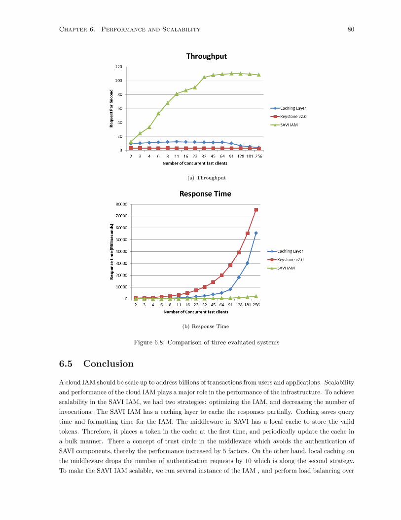
Chapter 6. Performance and Scalability 80
(a) Throughput
(b) Response Time
Figure 6.8: Comparison of three evaluated systems
6.5 Conclusion
A cloud IAM should be scale up to address billions of transactions from users and applications. Scalability
and performance of the cloud IAM plays a major role in the performance of the infrastructure. To achieve
scalability in the SAVI IAM, we had two strategies: optimizing the IAM, and decreasing the number of
invocations. The SAVI IAM has a caching layer to cache the responses partially. Caching saves query
time and formatting time for the IAM. The middleware in SAVI has a local cache to store the valid
tokens. Therefore, it places a token in the cache at the first time, and periodically update the cache in
a bulk manner. There a concept of trust circle in the middleware which avoids the authentication of
SAVI components, thereby the performance increased by 5 factors. On the other hand, local caching on
the middleware drops the number of authentication requests by 10 which is along the second strategy.
To make the SAVI IAM scalable, we run several instance of the IAM , and perform load balancing over

Chapter 6. Performance and Scalability 81
them. This method is very flexible because the IAM can be scaled up and down when the number
of requests changes. The advantages of the SAVI IAM over Openstack Keystone are threefold. The
throughput is 10 times higher in large number of requests. It can be is flexibly scale up and down. It is
more robust when in peak usage.

Chapter 7
Conclusion and Future scope
7.1 Future work
Our Future work mainly focus on federation of users. We intend to to be federated with other cloud
providers (e.g., Amazon EC2) and other testbeds (e.g., GENI). We have two technical issues down the
road: Authentication and Authorization. Format of identities are different among different providers,
therefore, we need to either conform to the target provider format or we can use a standard solution such
as Shibboleth. The second problem is authorization, and how to reach a unique interpretation from access
policies. There are several standards for cross-domain access policy interoperation such as eXtensible
Access Control Markup Language (XACML) which can be used to be federated in authorization as well.
The second part of our Future work focuses on new methods of Authentication such as QR-Code,
and biometrics. We are very interested to incorporate new methods of authentication to improve the
security of testbed.
7.2 Conclusion
This thesis presents a novel architecture to perform identity and access management(IAM) in a Multi-
tier cloud infrastructure.Multi-tier cloud is the next generation of the cloud computing concentrating
on the future applications requirements, and integrated the computing and communication. In the
Multi-tier cloud, service providers can offer different resources in different nodes, and these services
are supported by massive-scale data centers over the Internet. Multi-tier cloud infrastructure borrowed
tier-based model from Software Engineering to provide resources in different layers. In this research,
we focus on design and implementation of a flexible centralized identity and access management system
for the multi-tier cloud infrastructure. We use spiral software development methodology for developing
the IAM. Each spiral collects and analyzes a set of requirements, followed by a design to address these
requirements. This thesis conducted three level of analysis on the IAM including: identity management,
access control, and scalability. Identity management focuses on general concept of IAM and authentica-
tion. Access management provides a fine-grained access control in order to preserve the flexibility and
programmability of the infrastructure while improving the security. As an essential requirement of a
large-scale system, scalability enables the IAM to handle the large number of requests coming from the
cloud. In terms of throughput, the SAVI IAM outperforms Openstack Keystone v2.0 by a factor of 10
82

Chapter 7. Conclusion and Future scope 83
in high volume of requests, and it shows more stability too.

Bibliography
[1] Hasan Ibne Akram and Mario Hoffmann. User-centric identity management in ambient environ-
ments. International Journal On Advances in Intelligent Systems, 2(1):254–267, 2009.
[2] P. Angin, B. Bhargava, R. Ranchal, N. Singh, M. Linderman, L.B. Othmane, and L. Lilien. An
entity-centric approach for privacy and identity management in cloud computing. In Reliable Dis-
tributed Systems, 2010 29th IEEE Symposium on, pages 177–183, 2010.
[3] Michael Armbrust, Armando Fox, Rean Griffith, Anthony D. Joseph, Randy Katz, Andy Konwin-
ski, Gunho Lee, David Patterson, Ariel Rabkin, Ion Stoica, and Matei Zaharia. A view of cloud
computing. Commun. ACM, 53(4):50–58, April 2010.
[4] Ilia Baldine, Yufeng Xin, Anirban Mandal, Paul Ruth, Chris Heermann, and Jeff Chase. Exogeni:
A multi-domain infrastructure-as-a-service testbed. In Thanasis Korakis, Michael Zink, and Max-
imilian Ott, editors, TRIDENTCOM, volume 44 of Lecture Notes of the Institute for Computer
Sciences, Social Informatics and Telecommunications Engineering, pages 97–113. Springer, 2012.
[5] Barry W. Boehm. Software risk management: Principles and practices. IEEE Softw., 8(1):32–41,
January 1991.
[6] Jan Camenisch, Ronald Leenes, and Dieter Sommer, editors. Digital Privacy - PRIME - Privacy
and Identity Management for Europe, volume 6545 of Lecture Notes in Computer Science. Springer,
2011.
[7] Kim Cameron and Michael B Jones. Design rationale behind the identity metasystem architecture.
In ISSE/SECURE 2007 Securing Electronic Business Processes, pages 117–129. Springer, 2007.
[8] A. Celesti, F. Tusa, M. Villari, and A. Puliafito. Security and cloud computing: Intercloud identity
management infrastructure. In Enabling Technologies: Infrastructures for Collaborative Enterprises
(WETICE), 2010 19th IEEE International Workshop on, pages 263–265, 2010.
[9] Antonio Celesti, Francesco Tusa, Massimo Villari, and Antonio Puliafito. Three-phase cross-cloud
federation model: The cloud sso authentication. In Advances in Future Internet (AFIN), 2010
Second International Conference on, pages 94–101. IEEE, 2010.
[10] Ni Dan, Shi Hua-Ji, Chen Yuan, and Guo Jia-Hu. Attribute based access control (abac)-based
cross-domain access control in service-oriented architecture (soa). In Computer Science Service
System (CSSS), 2012 International Conference on, pages 1405–1408, 2012.
84

Bibliography 85
[11] Juan Du, N. Shah, and Xiaohui Gu. Adaptive data-driven service integrity attestation for multi-
tenant cloud systems. In Quality of Service (IWQoS), 2011 IEEE 19th International Workshop on,
pages 1–9, 2011.
[12] Jaliya Ekanayake and Geoffrey Fox. High performance parallel computing with clouds and cloud
technologies. In Cloud Computing, pages 20–38. Springer, 2010.
[13] Tewfiq El Maliki and Jean-Marc Seigneur. User-centric mobile identity management services. In
SECURWARE International Conference, 2007.
[14] November An Electronic, Len Lapadula, The Original, D. Elliott Bell, and Leonard J. Lapadula.
Secure computer systems: Mathematical foundations.
[15] ExoGENI. Exogeni, 2013.
[16] M. C. Ferrer. Zeus in the cloud, December 2009.
[17] Eclipse Foundation. Higgins: Personal data service, 2013.
[18] Eric Freudenthal, Tracy Pesin, Lawrence Port, Edward Keenan, and Vijay Karamcheti. drbac:
Distributed role-based access control for dynamic coalition environments. In ICDCS, pages 411–
420, 2002.
[19] Martin Gaedke, Johannes Meinecke, and Martin Nussbaumer. A modeling approach to federated
identity and access management. In Special interest tracks and posters of the 14th international
conference on World Wide Web, WWW ’05, pages 1156–1157, New York, NY, USA, 2005. ACM.
[20] GENI. Geni wiki, 2013.
[21] Anu Gopalakrishnan. Cloud Computing Identity Management. SETLabs Briefings, 7(7):45, 2009.
[22] Nagajyothi Gunti, Weiqing Sun, and Mohammed Y. Niamat. I-rbac: Isolation enabled role-based
access control. In PST, pages 79–86. IEEE, 2011.
[23] A. Hayat. A Pan European Interoperable Electronic Identity. PhD thesis, Graz University of
Technology, Austria, 2007.
[24] Markus Hillenbrand, Joachim Gotze, Jochen Muller, and Paul Muller. A single sign-on framework
for web-services-based distributed applications. In Proceedings of the 8th International Conference
on Telecommunications ConTEL (Zagreb, Croatia), volume 6, 2005.
[25] Michael Howard and David Leblanc. Writing Secure Code. Microsoft Press, Redmond, WA, USA,
2001.
[26] He Yuan Huang, Bin Wang, Xiao Xi Liu, and Jing Min Xu. Identity federation broker for service
cloud. In Proceedings of the 2010 International Conference on Service Sciences, ICSS ’10, pages
115–120, Washington, DC, USA, 2010. IEEE Computer Society.
[27] Amazon Inc. Aws govcloud (us) region government cloud computing, 2013.
[28] Amazon Inc. Aws identity and access management (iam), 2013.
Bibliography 86
[29] Rackspace Inc. Rackspace identity api, 2013.
[30] M. Jensen, N. Gruschka, and N. Luttenberger. The impact of flooding attacks on network-based
services. In Availability, Reliability and Security, 2008. ARES 08. Third International Conference
on, pages 509–513, 2008.
[31] Jerry Archer, Alan Boehme, Dave Cullinane, Nils Puhlmann, Paul Kurtz, Jim Reavis. CLOUD
SECURITY ALLIANCE SecaaS DEFINED CATEGORIES OF SERVICE, 2011.
[32] Audun Jøsang and Simon Pope. User centric identity management. In AusCERT Asia Pacific
Information Technology Security Conference, page 77. Citeseer, 2005.
[33] Audun Jøsang, Muhammed Al Zomai, and Suriadi Suriadi. Usability and privacy in identity man-
agement architectures. In Proceedings of the fifth Australasian symposium on ACSW frontiers -
Volume 68, ACSW ’07, pages 143–152, Darlinghurst, Australia, Australia, 2007. Australian Com-
puter Society, Inc.
[34] B.R. Kandukuri, V.R. Paturi, and A. Rakshit. Cloud security issues. In Services Computing, 2009.
SCC ’09. IEEE International Conference on, pages 517–520, 2009.
[35] Joon-Myung Kang, Hadi Bannazadeh, and Alberto Leon-Garcia. Savi testbed: Control and man-
agement of converged virtual ict resources. In Integrated Network Management (IM 2013), 2013
IFIP/IEEE International Symposium on, pages 664–667, 2013.
[36] K. Karnad and S. Nagenthram. Cloud security: Can the cloud be secured? In Internet Technology
And Secured Transactions, 2012 International Conferece For, pages 208–210, 2012.
[37] A.H. Karp. Authorization-based access control for the services oriented architecture. In Creating,
Connecting and Collaborating through Computing, 2006. C5 ’06. The Fourth International Confer-
ence on, pages 160–167, 2006.
[38] Alan H. Karp, Harry Haury, and Michael H. Davis. From abac to zbac: The evolution of access
control models. Technical report, Hewlett-Packard laboratories, 2009.
[39] Samuel T King and Peter M Chen. Subvirt: Implementing malware with virtual machines. In
Security and Privacy, 2006 IEEE Symposium on, pages 14–pp. IEEE, 2006.
[40] H. Koshutanski, F. Martinelli, P. Mori, and A. Vaccarelli. Fine-grained and history-based access
control with trust management for autonomic grid services. In Autonomic and Autonomous Systems,
2006. ICAS ’06. 2006 International Conference on, pages 34–34, 2006.
[41] Brian Krebs. Amazon: Hey spammers, get off my cloud. Washington Post (July 2008), 2008.
[42] Steve Lipner. The trustworthy computing security development lifecycle. In Proceedings of the 20th
Annual Computer Security Applications Conference, ACSAC ’04, pages 2–13, Washington, DC,
USA, 2004. IEEE Computer Society.
[43] Rongxing Lu, Xiaodong Lin, Xiaohui Liang, and Xuemin (Sherman) Shen. Secure provenance:
the essential of bread and butter of data forensics in cloud computing. In Proceedings of the 5th
ACM Symposium on Information, Computer and Communications Security, ASIACCS ’10, pages
282–292, New York, NY, USA, 2010. ACM.
Bibliography 87
[44] Tim Mather, Subra Kumaraswamy, and Shahed Latif. Cloud security and privacy. Theory in
practice. O’Reilly, Beijing, Cambridge, Mass., 2009.
[45] Tim Mather, Subra Kumaraswamy, and Shahed Latif. Cloud Security and Privacy: An Enterprise
Perspective on Risks and Compliance. O’Reilly Media, Inc., 2009.
[46] J. P. McDermott. Attack net penetration testing. In Proceedings of the 2000 workshop on New
security paradigms, NSPW ’00, pages 15–21, New York, NY, USA, 2000. ACM.
[47] Peter Mell and Tim Grance. Effectively and Securely Using the Cloud Computing Paradigm, May
2009.
[48] Peter Mell and Timothy Grance. The nist definition of cloud computing (draft). NIST special
publication, 800(145):7, 2011.
[49] R. L. Morgan, Scott Cantor, Steven Carmody, Walter Hoehn, and Ken Klingenstein. Federated
Security: The Shibboleth Approach. EDUCAUSE Quarterly, 27(4):12–17, 2004.
[50] Suvda Myagmar, Adam J Lee, and William Yurcik. Threat modeling as a basis for security require-
ments. In Symposium on Requirements Engineering for Information Security (SREIS), 2005.
[51] Srijith K Nair, Sakshi Porwal, Theo Dimitrakos, Ana Juan Ferrer, Johan Tordsson, Tabassum Sharif,
Craig Sheridan, Muttukrishnan Rajarajan, and Afnan Ullah Khan. Towards secure cloud bursting,
brokerage and aggregation. In Web Services (ECOWS), 2010 IEEE 8th European Conference on,
pages 189–196. IEEE, 2010.
[52] Mark Needleman. The shibboleth authentication/authorization system. Serials Review, 30(3):252
– 253, 2004.
[53] Peter Mell and Tim Grance. The NIST Definition of Cloud Computing, 2009.
[54] Michael Price. The paradox of security in virtual environments. Computer, 41(11):22–28, 2008.
[55] ProtoGENI. Protogeni, 2013.
[56] R. Ranchal, B. Bhargava, L.B. Othmane, L. Lilien, Anya Kim, Myong Kang, and M. Linderman.
Protection of identity information in cloud computing without trusted third party. In Reliable
Distributed Systems, 2010 29th IEEE Symposium on, pages 368–372, 2010.
[57] Kui Ren, Cong Wang, and Qian Wang. Toward secure and effective data utilization in public cloud.
Network, IEEE, 26(6):69–74, 2012.
[58] Thomas Ristenpart, Eran Tromer, Hovav Shacham, and Stefan Savage. Hey, you, get off of my
cloud: exploring information leakage in third-party compute clouds. In Proceedings of the 16th
ACM conference on Computer and communications security, pages 199–212. ACM, 2009.
[59] Thomas Ristenpart, Eran Tromer, Hovav Shacham, and Stefan Savage. Hey, you, get off of my
cloud: exploring information leakage in third-party compute clouds. In Proceedings of the 16th
ACM conference on Computer and communications security, CCS ’09, pages 199–212, New York,
NY, USA, 2009. ACM.

Bibliography 88
[60] C. Sample and D. Kelley. Cloud computing security: Routing and dns security threats, 2013.
[61] Ravi S. Sandhu, Edward J. Coyne, Hal L. Feinstein, and Charles E. Youman. Role-based access
control models. Computer, 29(2):38–47, February 1996.
[62] Bruce Schneier. Attack Trees: Modeling Security Threats. Dr. Dobb’s Journal, December 1999.
[63] Rob Sherwood, Glen Gibb, Kok-Kiong Yap, Guido Appenzeller, Martin Casado, Nick McKeown,
and Guru Parulkar. Can the production network be the testbed? In Proceedings of the 9th USENIX
conference on Operating systems design and implementation, OSDI’10, pages 1–6, Berkeley, CA,
USA, 2010. USENIX Association.
[64] Dawn Xiaodong Song, David Wagner, and Xuqing Tian. Timing analysis of keystrokes and timing
attacks on ssh. In Proceedings of the 10th conference on USENIX Security Symposium - Volume
10, SSYM’01, pages 25–25, Berkeley, CA, USA, 2001. USENIX Association.
[65] Maicon Stihler, Altair Olivo Santin, Arlindo L. Marcon Jr., and Joni da Silva Fraga. In Albert Levi,
Mohamad Badra, Matteo Cesana, Mona Ghassemian, zgr Grbz, Nafa Jabeur, Marek Klonowski,
Antonio Maa, Susana Sargento, and Sherali Zeadally, editors, NTMS.
[66] H. Takabi, J.B.D. Joshi, and Gail-Joon Ahn. Security and privacy challenges in cloud computing
environments. Security Privacy, IEEE, 8(6):24–31, 2010.
[67] Luis M. Vaquero, Luis Rodero-Merino, Juan Caceres, and Maik Lindner. A break in the clouds:
towards a cloud definition. SIGCOMM Comput. Commun. Rev., 39(1):50–55, December 2008.
[68] Ping Wang, Wen-Hui Lin, Pu-Tsun Kuo, Hui-Tang Lin, and Tzu Chia Wang. Threat risk anal-
ysis for cloud security based on attack-defense trees. In Computing Technology and Information
Management (ICCM), 2012 8th International Conference on, volume 1, pages 106–111. IEEE, 2012.
[69] Ping Wang, Wen-Hui Lin, Pu-Tsun Kuo, Hui-Tang Lin, and Tzu Chia Wang. Threat risk anal-
ysis for cloud security based on attack-defense trees. In Computing Technology and Information
Management (ICCM), 2012 8th International Conference on, volume 1, pages 106–111, 2012.
[70] Aaron Weiss. Computing in the clouds. netWorker, 11(4):16–25, December 2007.
[71] E. Yuan and J. Tong. Attributed based access control (abac) for web services. In Web Services,
2005. ICWS 2005. Proceedings. 2005 IEEE International Conference on, pages –569, 2005.
[72] Olive Qing Zhang, Markus Kirchberg, Ryan K. L. Ko, and Bu-Sung Lee. How to track your data:
The case for cloud computing provenance. In Costas Lambrinoudakis, Panagiotis Rizomiliotis, and
Tomasz Wiktor Wlodarczyk, editors, CloudCom, pages 446–453. IEEE, 2011.
[73] Qi Zhang, Lu Cheng, and Raouf Boutaba. Cloud computing: state-of-the-art and research chal-
lenges. J. Internet Services and Applications, 1(1):7–18, 2010.
[74] Xinwen Zhang, Sejong Oh, and Ravi Sandhu. Pbdm: a flexible delegation model in rbac. In
Proceedings of the eighth ACM symposium on Access control models and technologies, pages 149–
157. ACM, 2003.