by order of the air force instruction 11-2ae...
TRANSCRIPT
BY ORDER OF THE
SECRETARY OF THE AIR FORCE
AIR FORCE INSTRUCTION 11-2AE VOLUME
3, ADDENDA-A
17 MAY 2011
Incorporating Change 1, 12 JULY 2012
Flying Operations
AEROMEDICAL EVACUATION
OPERATIONS CONFIGURATION/MISSION
PLANNING
COMPLIANCE WITH THIS PUBLICATION IS MANDATORY
ACCESSIBILITY: Publications and forms are available for downloading or ordering on the e-
Publishing website at www.e-Publishing.af.mil.
RELEASABILITY: There are no releasability restrictions on this publication.
OPR: AMC/A3VM
Supersedes: AFI11-2AEV3ADDENDA-A,
27 May 2005
Certified by: AF/A3O-A
(Col James W. Crowhurst)
Pages: 85
This supporting instruction implements AFPD 11-2, Aircraft Rules and Procedures. It establishes
policy for the basic aeromedical evacuation (AE) configurations for C-130, C-17, KC-135, and
C-21 aircraft to safely and successfully accomplish their worldwide AE missions. The use of the
name or mark of any specific manufacturer, commercial product, commodity, or service in this
publication does not imply endorsement by the Air Force. This instruction is applicable to Air
Force Reserve Command (AFRC), Air National Guard (ANG) units, Pacific Air Forces
(PACAF), U. S. Air Forces in Europe (USAFE), and Air Mobility Command (AMC). (ANG is
considered to be a Major Command (MAJCOM) throughout this publication.) This AFI applies
to aircrew members, support personnel, and managers involved with Aeromedical operations.
This AFI provides necessarily broad guidance and cannot address every conceivable
circumstance. This publication requires the collection and or maintenance of information
protected by the Privacy Act (PA) of 1974. The authority for maintenance of Aviation Resource
Management System (ARMS) is Title 37 U.S.C. 301a Incentive Pay: Aviation Career, Public
Law 92-204, Section 715 Appropriations Act for 1973, Public Laws 93-570 Appropriations Act
for 1974, Public Law 93-294 Aviation Career Incentive Act of 1974, and Executive Order 9397,
Numbering System for Federal Accounts Relating to Individual Persons, as amended by
Executive Order 13478, Amendments to Executive Order 9397 Relating to Federal Agency Use
of Social Security Numbers, November 18, 2008. Ensure that all records created as a result of
processes prescribed in this publication are maintained in accordance with AFMAN 33-363,
Management of Records, and disposed of in accordance with the Air Force Records Disposition
Schedule (RDS) located at https://www.my.af.mil/afrims/afrims/afrims/rims.cfm. The
2 AFI11-2AEV3ADDENDA-A 17 MAY 2011
Paperwork Reduction Act of 1995 as amended in 1996 affects this instruction. Refer
recommended changes and questions about this publication to the Office of Primary
Responsibility (OPR) using the AF Information Management Tool (Form) 847,
Recommendation for Change of Publication; route AF Form 847s from the field through the
appropriate functional chain of command. Send comments and suggested improvements to this
instruction through channels to AMC/A3V, 402 Scott Drive Unit 3A1, Scott AFB IL, 62225-
5302 according to AFI 11-215, USAF Flight Manuals Program (FMP), and MAJCOM
Supplement.
SUMMARY OF CHANGES
This interim change implements corrections made to C-130 Configurations Figures 4.1 AE-1 and
4.2 AE-2, updates total seats available in Table 6.1 Patient Planning Factors, and provides souls
on board guidance for AE missions IAW KC-135 Configurations and updates KC-135
Configurations Figures 6.1 AE-1 , 6.2 AE-2 and 6.3 AE-3. A margin bar (|) indicates newly
revised material.
Chapter 1—POLICY 7
1.1. General. .................................................................................................................. 7
1.2. Responsibility. ....................................................................................................... 7
1.3. Modifications. ........................................................................................................ 7
1.4. Distribution. ........................................................................................................... 8
1.5. Deviations and Waivers. ........................................................................................ 8
1.6. Revisions. ............................................................................................................... 8
1.7. Supplements. .......................................................................................................... 8
1.8. AE Medical Equipment. ......................................................................................... 8
Chapter 2—AIRCREW FLIGHT EQUIPMENT (AFE) 9
2.1. Aircraft Flight Equipment (AFE) Configuration. .................................................. 9
2.2. Emergency Passenger Oxygen System (EPOS): ................................................... 9
2.3. Oxygen Mask. ........................................................................................................ 11
2.4. Protective Breathing Equipment (PBE)/Emergency Escape Breathing Device
(EEBD). ................................................................................................................. 11
2.5. Life Preserver Units (LPU): ................................................................................... 11
2.6. Life Rafts. .............................................................................................................. 11
2.7. Civil Reserve Air Fleet (CRAF) Missions. ............................................................ 11
Chapter 3—AIRCRAFT SUPPORT EQUIPMENT 13
3.1. PATIENT SUPPORT PALLET (PSP). ................................................................. 13

AFI11-2AEV3ADDENDA-A 17 MAY 2011 3
3.2. Description. ............................................................................................................ 13
3.3. Requirements. ........................................................................................................ 13
3.4. AE Mission Execution. .......................................................................................... 13
3.5. Responsibilities. ..................................................................................................... 13
3.6. USAFE and PACAF Interface. .............................................................................. 14
3.7. Configurations. ...................................................................................................... 15
Table 3.1. PSP CONFIGURATION WEIGHTS. ................................................................... 15
Table 3.2. PSP PART WEIGHTS. .......................................................................................... 15
Figure 3.1. PSP-L. .................................................................................................................... 16
Figure 3.2. PSP-W. ................................................................................................................... 16
Figure 3.3. PSP-S. .................................................................................................................... 16
Figure 3.4. PSP-M. ................................................................................................................... 17
3.8. Stanchion Assembly. ............................................................................................. 17
Figure 3.5. Seat Track Fitting. .................................................................................................. 17
Figure 3.6. AFT Stanchion Assembly. ..................................................................................... 18
Figure 3.7. AFT Stanchion Assembly. ..................................................................................... 18
Figure 3.8. Forward Stanchion Assembly. ............................................................................... 19
Figure 3.9. Forward Stanchion Assembly. ............................................................................... 19
Figure 3.10. Tension Bar Assembly. .......................................................................................... 20
Figure 3.11. Tension Bar Assembly. .......................................................................................... 20
Figure 3.12. Tension Bar Assembly. .......................................................................................... 20
Figure 3.13. Tension Bar Assembly. .......................................................................................... 21
Figure 3.14. Tension Bar Assembly. .......................................................................................... 21
Figure 3.15. Tension Bar Assembly. .......................................................................................... 22
3.9. Seat Assembly. ....................................................................................................... 22
Figure 3.16. Seat Assembly. ....................................................................................................... 22
Figure 3.17. Seat Assembly. ....................................................................................................... 22
Figure 3.18. Seat Assembly. ....................................................................................................... 23
Figure 3.19. Seat Assembly. ....................................................................................................... 23
3.10. Litter Installation. ................................................................................................... 23
Figure 3.20. Litter Installation. ................................................................................................... 24
Figure 3.21. Litter Installation. ................................................................................................... 24
Figure 3.22. Litter Installation. ................................................................................................... 24

4 AFI11-2AEV3ADDENDA-A 17 MAY 2011
Figure 3.23. Litter Installation. ................................................................................................... 25
Figure 3.24. Litter Installation. ................................................................................................... 25
Figure 3.25. Litter Installation. ................................................................................................... 25
3.11. Enplaning and Deplaning. ...................................................................................... 25
3.12. Patient Care Procedures. ........................................................................................ 26
3.13. Maintenance. .......................................................................................................... 26
3.14. Disassembly and Storage. ...................................................................................... 27
3.15. KC-135 PSP CONFIGURATION. ........................................................................ 27
3.16. C-17 PSP CONFIGURATION. ............................................................................. 29
3.17. PSP Inventory. ....................................................................................................... 29
3.18. PSP Spare Parts Repair Kit. ................................................................................... 30
3.19. PSP Inspection. ...................................................................................................... 30
3.20. Litter Station Augmentation Set (LSAS). .............................................................. 30
CHAPTER 4—C130 E, H, J CONFIGURATIONS 34
4.1. Aircraft Systems. ................................................................................................... 34
Table 4.1. C130 PATIENT PLANNING FACTORS. ............................................................ 34
Figure 4.1. AE-1. ...................................................................................................................... 35
Figure 4.2. AE-2. ...................................................................................................................... 35
Figure 4.3. AE-3. ...................................................................................................................... 36
Figure 4.4. AE-4. ...................................................................................................................... 37
Figure 4.5. AE-5. ...................................................................................................................... 38
Figure 4.6. AE-1 (C-130J-30) C-130J-30 CONFIGURATIONS. ........................................... 39
Figure 4.7. AE-2 (C-130J-30). ................................................................................................. 40
Figure 4.8. AE-3 (C-130J-30). ................................................................................................. 41
Figure 4.9. AE-4 (C-130J-30). ................................................................................................. 42
Figure 4.10. AE-5 (C-130J-30). ................................................................................................. 42
CHAPTER 5—C-17 PATIENT PLANNING FACTORS 44
5.1. Aircraft Systems. ................................................................................................... 44
Table 5.1. Patient Planning Factors. ....................................................................................... 44
Figure 5.1. AE-1 Configuration. .............................................................................................. 46
Figure 5.2. AE-2 Configuration. .............................................................................................. 47
Figure 5.3. AE-3 Configuration. .............................................................................................. 48
Figure 5.4. AE-C1 Configuration. ............................................................................................ 49
AFI11-2AEV3ADDENDA-A 17 MAY 2011 5
CHAPTER 6—KC-135 CONFIGURATIONS 51
6.1. Mission Execution. ................................................................................................ 51
6.2. Aircraft Systems. ................................................................................................... 51
6.3. Miscellaneous Information. ................................................................................... 53
6.4. Egress Considerations. ........................................................................................... 54
Table 6.1. KC-135 Patient Planning Factors. .......................................................................... 54
Figure 6.1. AE-1. ...................................................................................................................... 56
Figure 6.2. AE-2. ...................................................................................................................... 57
Figure 6.3. AE-3. ...................................................................................................................... 58
Figure 6.4. AE-3 – CCATT 1 Non-Vented. ............................................................................. 59
Figure 6.5. AE-3 – CCATT 2 Non-Vented. ............................................................................. 60
Figure 6.6. AE-3 – CCATT 3 Non-Vented. ............................................................................. 61
Figure 6.7. AE-3 – CCATT 1 Vented. ..................................................................................... 62
Figure 6.8. AE-3 – CCATT 2 Vented. ..................................................................................... 63
Figure 6.9. AE-3 – CCATT 3 Vented. ..................................................................................... 64
Figure 6.10. KC-135 Circuit Breaker Panel. .............................................................................. 65
Chapter 7—C-21 CONFIGURATION 66
7.1. SPECTRUM 500-LP (MILITARY VERSION) MODEL 2500US. ...................... 66
7.2. Loading Instructions for Neonatal Transport System (NTS) onto SPECTRUM
Unit. ....................................................................................................................... 69
7.3. Additional C-21 Configuration (AE-2 Configuration {1 Stretcher}) IAW TO-1C-
21A-1. .................................................................................................................... 70
7.4. Aircraft Systems. ................................................................................................... 70
Figure 7.1. AE-1 Configuration. .............................................................................................. 71
Table 7.1. AE-1 Planning Factors. .......................................................................................... 71
Figure 7.2. AE-2 Configuration. .............................................................................................. 72
Table 7.2. AE-2 Planning Factors. .......................................................................................... 72
Chapter 8—FLOOR LOADING 74
8.1. C-130 Floor Loading. ............................................................................................ 74
Figure 8.1. C-130 One Litter. ................................................................................................... 74
Figure 8.2. C-130 Two Litters. ................................................................................................. 75
Figure 8.3. C-130 Three Litters. ............................................................................................... 75
8.2. C-17 Floor Loading. .............................................................................................. 75
6 AFI11-2AEV3ADDENDA-A 17 MAY 2011
Figure 8.4. C-17 One Litter. ..................................................................................................... 76
Figure 8.5. C-17 Two Litters. ................................................................................................... 77
Figure 8.6. C-17 Three Litters. ................................................................................................. 77
8.3. KC-135 Floor Loading. .......................................................................................... 78
Figure 8.7. KC-135 Two Litters. .............................................................................................. 78
Chapter 9—OPPORTUNE AIRCRAFT SYSTEMS 79
9.1. KC-10 Systems. ..................................................................................................... 79
9.2. C-5 Systems. .......................................................................................................... 79
Attachment 1—GLOSSARY OF REFERENCES AND SUPPORTING INFORMATION 81
AFI11-2AEV3ADDENDA-A 17 MAY 2011 7
Chapter 1
POLICY
1.1. General. This instruction establishes basic cargo compartment configuration, standard
equipment, and location of such equipment aboard the C-130, C-17, KC-135, and C-21 aircraft.
Opportune aircraft systems, KC-10 and C-5 are identified. Some aircraft have additional
equipment installed that may affect configuring the aircraft as listed. The cargo compartment
limitations listed herein are the most typical encountered in day-to-day operations. The times
quoted are approximate figures and are configuration times only. They do not include de-
configuration times. Aeromedical Evacuation Crews (AEC) do not require parachutes. Mission
Design Series (MDS) specific survival equipment is for primary flight crewmembers only.
Instructions in this AFI are mandatory and provide the best possible operating instructions under
most circumstances, but cannot account for every possible situation that a crewmember may
encounter during contingency operations. During these times, the AEC must use sound judgment
and operational risk management to meet mission demands.
1.1.1. Applicability. This AFI is applicable to all AE units/individuals involved with AE
operations. It is a compilation of information from aircraft flight manuals, other Air Force
directives, as well as an original source document for many areas. Basic source directives
have precedence in the case of any conflicts, revisions, and matters of interpretation. For
those areas where this AFI is the source document, waiver authority will be in accordance
with paragraph 1.5.2 For those areas where this AFI repeats information contained in other
source documents, waiver authority will be in accordance with source documents.
1.1.2. This AFI provides necessarily broad guidance and cannot address every conceivable
circumstance. Medical Crew Directors (MCD)/Charge Medical Technicians (CMT) are
expected to use their best judgment to ensure the safe conduct of the flight.
1.2. Responsibility. Personnel engaged in planning operations must consider the most
appropriate configuration that satisfies mission requirements and permits the minimum amount
of variations and man-hours to change. United States Air Force (USAF) units performing
services on the aircraft (i.e., Maintenance, Aerial Port, and Aircrew Flight Equipment) are
responsible for configuring the aircraft in accordance with (IAW) appropriate 11-2MDS V3
Addenda A instruction and as outlined in mission directives, to include the stowage/installation
of the equipment IAW the configuration and equipment tables outlined herein. The aircrew will
normally accomplish some configurations with assistance by maintenance personnel. Aircrew
personnel, during preflight, will ensure that required mission equipment has been provided and is
properly installed. When the aircraft configuration is not completed prior to aircrew show time,
the loadmaster (LM) or boom operator (BO) will assist in the completion of the configuration,
after accomplishing required predeparture duties (i.e., preflight, loading, etc.). Items that can be
corrected without maintenance assistance (i.e., seat belts, seat hooks, etc.) will be corrected by
the LM/BO. LM’s/BO’s have overall responsibility for configuration management and proper
installation of equipment on the aircraft.
1.3. Modifications. The configuration codes of this AFI may, if necessary, require
modifications for a specific mission. Each modification must be carefully evaluated prior to
mission operation to ensure maximum flight safety and compatibility with aircraft equipment.
Each mission directive will identify the basic configuration by code and the modification, if
8 AFI11-2AEV3ADDENDA-A 17 MAY 2011
necessary, to satisfy the mission requirement. For example, an AE mission may require more
litters than available in configuration AE-1. Consult the appropriate configuration charts to
determine at what location the desired additional litters can be installed and which seats must be
removed. Indicate in the mission directive, by position (left or right, and number) which seats are
to be deleted and (by alphabetical position) the litter tier provisions to be installed.
1.4. Distribution. See AFI 11-2AEV3, Aeromedical Evacuation (AE) Operations Procedures,
Chapter 1 and apply the following: Maintain at least one copy of this instruction in each
squadron operations section (FCIF Library). The following agencies should have direct access
(latest electronic version) or paper copy: Staff operations, Aircrew Stan/Eval, Command
Posts/operations centers, Air freight management, Fleet Service, Aircraft Maintenance units,
alternate mission equipment sections, quality control, and Aircrew Flight Equipment sections,
one paper copy for each supplemental weight and balance handbook aboard each aircraft.
1.5. Deviations and Waivers.
1.5.1. Do not deviate from the policies and guidance in this AFI under normal
circumstances, except:
1.5.1.1. For safety.
1.5.1.2. When necessary to protect the crew, patients, passengers (PAX) or aircraft from
a situation not covered by this AFI and immediate action is required. The pilot in
command (PIC) is the ultimate authority and responsible for the course-of-action to be
taken. Report deviations or exceptions without waiver through channels to Major
Command Office of Primary Responsibility (MAJCOM OPR).
1.5.2. Waivers. Unless otherwise directed, waiver authority for contents of this instruction is
the MAJCOM/A3/DO with mission execution authority. Obtain waivers to deviate from
provisions in this AFI via MAJCOM Stan/Eval. For missions under AMC/TACC operational
control, direct all waiver requests directly to 618 TACC. EXCEPTION: Contingency
missions. Waiver authority for contingency missions will be listed in the Operations Order
(OPORD), Tasking Order (TO), etc., or is the Director of Mobility Forces (DIRMOBFOR)
(or equivalent) for the agency with Command and Control (C2) of the aircraft. Crewmembers
may request additional information or confirmation from their home units, Tanker Airlift
Control Center TACC, or MAJCOM/DO.
1.6. Revisions. Send comments and suggested improvements to this instruction on AF Form
847, Recommendation for Change of Publication, through channels to AMC/A3V, 402 Scott
Drive, Scott AFB IL., 62225-5302 IAW procedures in AFI 11-215, Flight Manual Procedures
and MAJCOM Supplement.
1.7. Supplements. Subordinate unit supplements to this instruction that change the basic
policies, procedures, or formats prescribed herein are prohibited.
1.8. AE Medical Equipment. AE equipment will be positioned as required by the Medical
Crew Director (MCD) based upon mission profile and patient requirements. Patient Therapeutic
Liquid Oxygen (PTLOX) will not be positioned adjacent to any hydraulic reservoir.
AFI11-2AEV3ADDENDA-A 17 MAY 2011 9
Chapter 2
AIRCREW FLIGHT EQUIPMENT (AFE)
2.1. Aircraft Flight Equipment (AFE) Configuration. AECs are required to utilize AFE to
accomplish the mission. Standard quantities of aircrew flight equipment are identified in this
instruction, MDS Specific 11-2MDS Vol 3, Addenda A. When an MDS specific Vol 3,
Addenda does not exist, refer to AFI 11-301, Vol 2, Maintenance and Configuration
Requirements for Aircrew Flight Equipment (AFE). MAJCOM’s may dictate other required
AFE. During AE contingency/deployment generations, it is imperative crewmembers deploy
with the full complement of AFE. This equipment must be at forward operating locations to
allow maximum mission flexibility when aircrews are away from home station. NOTE:
Demonstration of onboard Aircrew Flight Equipment (AFE) is required for all missions.
2.1.1. AFE units, when supporting AE missions and aircrew, will build and maintain the
equipment listed in Table 11 of AFI 11-301 Volume 2, Maintenance and Configuration
Requirements for Mobility Air Forces (MAF) Aircrew and Aircraft Flight Equipment (AFE).
The equipment will be placed in kits assigned to, and deployed with, an AE in-flight kit
(UTC FFQDM). EXCEPTION: PACAF and USAFE AFE squadrons supporting AE
operations will build and maintain eight kits. Individual MAJCOMs will direct what units
will maintain for local training and operational missions.
2.1.2. The AES will designate an individual to sign out the AECM Support Kit required to
support daily operations. AFE will issue the AECM Support Kit to the AES POC via an AF
Form 1297. In turn the AES POC will use an AF Form 1297 for controlling temporary issue
to AECMs utilizing the equipment for operational or training missions. The AES POC will
account for and return the issued AFE and MA-1 cylinders to AFE operations for
maintenance, inspection, and shipment.
2.1.3. AECMs are responsible for refilling and discharging the MA-1 oxygen issued by
AFE. Prior to turn in of the cylinder, the cylinder pressure will be reduced to between 5 and
38 PSIG gage pressure."
2.2. Emergency Passenger Oxygen System (EPOS):
2.2.1. EPOS is the preferred passenger oxygen, smoke, and fume protection.
2.2.2. The EPOS is a self-contained protective breathing device to provide oxygen during
aircraft decompressions, when smoke or toxic fumes are present, and to aid in exiting oxygen
deficient smoke filled cabins.
2.2.3. The system consists of a hood, oxygen cylinder, carbon dioxide control, and neck seal.
The hood incorporates multiple layers of Kapton and Teflon film providing heat and flame
resistant to 1000°C (1832° F), ease of communication, tear resistance, and durability. The
altitude restriction for the EPOS is FL 410 (41,000 feet).
2.2.4. An anti-fog coating is applied to the inside of the hood.
2.2.5. The EPOS contains one oxygen cylinder that contains 18 liters of aviator grade
oxygen. Once activated, the oxygen cylinder dispenses oxygen for approximately 5 minutes.
The sound of oxygen can be heard flowing into the hood. Once the oxygen cylinder has been
10 AFI11-2AEV3ADDENDA-A 17 MAY 2011
depleted, the hood will begin to collapse. If the hood collapses to the point where it touches
the wearer’s face, the wearer should be prepared to remove the EPOS. EPOS should also be
removed when the individual has evacuated to a safe area, or is directed to do so by a
qualified crewmember. Carbon dioxide (CO2) is controlled by panels of lithium hydroxide
mounted around the inside bottom portion of the hood.
2.2.6. Duration of Use:
2.2.6.1. 5 minutes under moderate to heavy workload.
2.2.6.2. 17 minutes of sedentary conditions followed by 3 minutes of moderate to heavy
workload.
2.2.6.3. Up to 60 minutes under sedentary conditions.
2.2.7. The AE crew is responsible for ensuring that there are enough EPOS units for each
AECM, patient, and attendant. On aircraft with the EPOS stored in a sealed container, a
preflight/postflight is to ensure that there are enough units inside the sealed container. If the
EPOS units are in open containers check the package seal, if the seal is broken, a preflight
consists of checking the color of the litmus paper on the humidity indicator disk located in
the barrier pouch and the expiration date. If the litmus paper is pink, the unit is not
serviceable.
2.2.8. For C-130 and KC-135 aircraft, ensure that there are EPOS units prepositioned at each
patient/ passenger positions. If not, work with the LM/BO to place one at each station. Secure
the EPOS on the upper seat support tube using the attached tie-down strap and quick release
snap. Position the EPOS bag to the forward side of the passenger and between the seat back
webbing to ensure rapid access.
2.2.9. For KC-135 aircraft, three additional EPOS should always be positioned with one in
the latrine, one in the cockpit, and one at the galley/galley area. Notify BO if they are not
there.
2.2.10. For aircraft with airline-type seating, EPOS will be placed in the seat pockets; assist
the BO/LM with handing out the EPOS to patients/passengers to be stored in seat pouches.
2.2.11. For C-17 aircraft, check for EPOS underneath each seat. Notify LM if they are
missing.
2.2.12. For litter patients, AECMs will secure the EPOS at the head of each litter.
WARNING: During activation, grasp the body, large round end of cylinder. Failure to do
so will restrict the metal tab from opening and activating the oxygen system. The EPOS will
not function without the removal of the metal tab. If the red knob separates, grasp the
lanyard to pull the metal tab off the cylinder and then proceed to use the EPOS as directed.
Failure to activate the flow of oxygen will reduce the level of oxygen inside the hood and
will result in suffocation and death. NOTE: Ensure hair, jewelry, shirt collars, etc are not
caught between the neck seal and neck. Reduced effectiveness of the EPOS may occur,
increasing the likelihood of injury.
2.2.13. For KC-135 aircraft, all AECMs will have emergency 02 immediately available
when moving about the cabin. NOTE: The EPOS is not an acceptable source of emergency
oxygen while performing crew duties. AECMs will don the EPOS, cease all crew duties and
be seated if there are no other oxygen sources available.
AFI11-2AEV3ADDENDA-A 17 MAY 2011 11
2.3. Oxygen Mask.
2.3.1. P/N 358-1506 series quick-don oxygen mask with goggles attached is the preferred
smoke and fume protection for primary AECMs.
2.4. Protective Breathing Equipment (PBE)/Emergency Escape Breathing Device (EEBD).
2.4.1. Units may utilize PBE/EEBD with the fire retardant polyethylene (green) storage
container and neoprene neck seal. PBE/EEBD will remain in their original "hard" carrying
case to provide fire and puncture-proof protection.
2.4.2. This device is a 15 minute, self-contained, completely disposable breathing unit, with
a solid state oxygen supply source. The universal size hood permits oral communication
without compromising protection.
2.4.3. AECM preflight consists of checking the color of the light blue litmus paper through
the serviceability window in the side of the case. If the litmus paper has turned pink, the unit
is no longer serviceable.
2.4.4. Maximum operating altitude is FL 400 (40,000 feet).
2.4.5. The containers are not to be opened unless an oxygen deficient, smoke-laden, or toxic
atmosphere exists. WARNING: Improper use may cause injury or death. User must have
adequate training to use. CAUTION: Ensure long hair or clothing is not caught in the neck
seal.
2.5. Life Preserver Units (LPU):
2.5.1. The adult/child (A/C) LPU is the preferred LPU for AECMs and patients/passengers
during ditching situations. The A/C LPU does not require pre-fitting prior to flight and is
easier to don during emergency situations. As a minimum, each aircraft will have one LPU
for each passenger during overwater flights. AECMs must notify BO/LM if there are not
enough A/C LPUs for each patient/PAX/AECM. The A/C LPU can be used on children
greater than 18 months old. The A/C LPU has the following components: Sea dye marker,
lanyard, water activated light, oral inflation tube and whistle.
2.5.2. The 10/P LPUs are required and designed to integrate with AFE. Adult/Child LPUs
are not compatible for use with AFE and will not be used as a substitute for these LPUs.
2.5.3. The life vests are inflated by pulling the red CO2 release tabs or orally by using the
oral inflation tubes.
2.5.4. LPU-6/P infant cot may be used for infants up to 18 months old. To use the LPU-6/P,
place the infant feet first into the cot with head towards open end of hood. Secure the infant
with restraining tape around the chest and across the upper thighs. For added protection, a
baby blanket should be placed around or under the infant before placing the infant in the cot.
The LPU-6/P has the following survival components: air ports, water activated light,
lanyard, oral inflation tubes, and webbing straps. NOTE: The LPU-6/P is the only life
preserver that can be inflated inside the aircraft.
2.6. Life Rafts.
2.6.1. AECMs will coordinate with PIC, LM/BO to ensure life rafts are available.
2.7. Civil Reserve Air Fleet (CRAF) Missions.

12 AFI11-2AEV3ADDENDA-A 17 MAY 2011
2.7.1. All AE aircrews flying on CRAF aircraft are exempt from having to use the AFE
except for the 358-series quick-don mask and MA-1 walk-around bottle and EPOS. This
equipment is required for protection from smoke and fumes and emergency decompressions.
Travis and Charleston AFBs AFE shops will maintain twelve (12) and thirteen (13) kits
respectively, containing seven (7) each LPU-6/P infant cot life preservers and eleven (11)
each EPOS to support AE CRAF missions. These CRAF support kits will only be mobilized
to support CRAF AE operations.
AFI11-2AEV3ADDENDA-A 17 MAY 2011 13
Chapter 3
AIRCRAFT SUPPORT EQUIPMENT
3.1. PATIENT SUPPORT PALLET (PSP).
3.2. Description. The PSP increases the number of aircraft capable of performing patient
movement during steady-state operations, times of war and military operations other than war.
The PSP is intended for use on C-17, KC-10 and KC-135 cargo aircraft only. The PSP is
manufactured to defined standards and tolerances that allow interchangeability of parts. The PSP
has a protective finish on parts that are not inherently corrosion resistant and includes fastening
devices that stay in position during service use. The PSP pallet base occupies the footprint of a
463L aircraft pallet. Standard airline seat track rails embedded in the surface of the pallet base
provide mounting for the airline type seats and litter stanchions. Eight seat track rails are
mounted in the 108-inch direction of the pallet base. The seat track rails are spaced at 12.60-inch
and 20.75-inch intervals.
3.2.1. The pallet surface is covered with a non-skid material and supports up to six airline-
type seats that are removable, forward or aft facing, and are Technical Standard Order (TSO)
C-39b certified. Each seat has a reclining backrest, a padded armrest, an in-arm bi-fold tray
table, a lap safety belt, a break-over backrest, and removable cloth upholstery. Each pallet
has one large red cross on the pallet to ease identification of the pallet from other 463L
pallets.
3.3. Requirements. The PSP is designed to support steady-state theater operational
requirements as well as patient movement on opportune airlift without integral litter capability.
These requirements include contingencies, humanitarian relief operation (HUMRO), Homeland
Defense, war, peacetime, routine and emergent missions.
3.3.1. Requirements are driven by the following factors: patients, aircraft, location factors to
include; Air Mobility Support Squadrons and location of tanker aircraft.
3.4. AE Mission Execution. The Aerial Port Control Center (APCC) or the Air Mobility
Control Center (AMCC) will notify aerial ports of outbound/inbound mission and support
requirements. PSPs will be transported and loaded onto aircraft IAW mission requirements/load
plan.
3.4.1. At en route locations, reconfiguration and/or removal of PSP components, resulting in
a change in either litter or ambulatory carrying capacity is not authorized, unless coordinated
with TACC/AE Cell.
3.5. Responsibilities.
3.5.1. Aircrew.
3.5.1.1. Review Global Decision Support System (GDSS), and Special Instructions
(SPINs) for mission changes/reconfigurations.
3.5.2. AE Personnel.
3.5.2.1. Coordinate with LM/BO for loading and securing the PSP onboard the aircraft.
14 AFI11-2AEV3ADDENDA-A 17 MAY 2011
3.5.2.2. All crewmembers will establish egress routes and ensure access to emergency
exits/equipment is not obstructed by the PSP.
3.5.3. The LM/BO and AECM shall ensure that there is a reasonable degree of access to the
rear of the aircraft, and that passengers and patients have ready access to emergency exits.
Load aircraft in such a manner that allows for movement from the flight deck to the cargo for
fire fighting.
3.5.3.1. Configure seats/litters on the PSP as required to meet mission requirements.
WARNING: Stanchion assembly and seat requires a two-person lift to prevent injury.
3.5.3.2. AECMs will inspect each PSP before and after mission use.
3.5.3.2.1. Damaged PSPs requiring major repair will be reported to the PSP
custodian (identified at base of origin) and documented using AFTO IMT 244,
Industrial/Support Equipment Record.
3.5.3.2.2. Immediate malfunctions/concerns will be resolved using crew Operational
Risk Management (ORM) principles.
3.5.3.2.3. An AECM or designee will process paperwork DD Form 1149, Requisition
and Invoice/Shipping Document and/or AFTO IMT 244. NOTE: The PSP custodian
should complete this form at home station, after contacting AMC/A38R for fund cite
information. The DD Form 1149 will travel with the AECMs and be given to the PSP
custodian upon return to home station.
3.5.4. Aerial Port.
3.5.4.1. Deliver and retrieve PSPs to and from the aircraft. The PSP was designed to
interface with the 463L pallet system. Load the PSP using same methodology as the 463L
pallet.
3.5.4.2. When it is anticipated that the PSP will leave and return to home station for a
single mission, PSP custodian (or designee) with assistance from aerial port personnel,
will remove/replace the rigid PSP storage cover as prescribed by local facility policy for
aircraft configuration. AECMs are responsible for breaking down the PSP into the
storage mode unless directed otherwise by APS personnel.
3.5.4.3. PSPs will be manifested and moved as 999 cargo IAW PSP concept of
operations (CONOPS).
3.5.5. 618 TACC/AE Cell.
3.5.5.1. Identifies configuration requirements in the Global Decision Support System
(GDSS), and Special Instructions (SPINs) for mission changes/reconfigurations.
3.5.5.2. Serve as conduit for information between AECMs, aerial port functions, and
other operational agencies when applicable.
3.5.5.3. When the PSP is tasked for a mission at other than home station; the PSP will be
moved in the cargo configuration (all components configured on the pallet in the cargo
configuration with the protective cover in place), unless coordinated with 618 TACC/AE
Cell.
3.6. USAFE and PACAF Interface.

AFI11-2AEV3ADDENDA-A 17 MAY 2011 15
3.6.1. PSPs in USAFE and PACAF will be managed by the AMC/Air Mobility Operations
Group (AMOG) at en route locations as determined by AMC/A3OE.
3.6.2. Theater AOC will request the use of the PSP through the AMC/AMOG. AMC/AMOG
is the granting authority when the PSP is required for use on non-AMC aircraft.
3.6.3. Command Relationships/Architecture. AMC will retain ownership of the PSPs to
allow for centralized oversight/budgeting and availability for intertheater mission execution.
3.7. Configurations.
3.7.1. The PSPs have been fielded in block increments. The Block 1 initial design supports
three litter patients per litter tier. An extension added to the litter tower of the Block 2 design
will support four litter patients per tier on the C-17.
Table 3.1. PSP CONFIGURATION WEIGHTS.
Table 3.2. PSP PART WEIGHTS.
3.7.2. The PSP can be configured in four different configurations. (Refer to Figure 3.1.
through Figure 3.4. for depiction of Block 1 initial design configurations).
3.7.3. Configuration options follow:
3.7.3.1. PSP-W: Two litter tiers along the outer aspect of the pallet supporting six to
eight litter patients. To facilitate egress, PSP-W will be used if maximum numbers of
twelve (12) PSP(s) are required.
3.7.3.2. PSP-L: Two litter tiers down the center of the PSP with litter arms facing out
supporting six to eight litter patients.
3.7.3.3. PSP-M: Three PSP seats and one litter tier along the outer aspect of the pallet
supporting up to three to four litter patients and three ambulatory patients. During an
inflight medical emergency, seats can be removed and placed off to the side to increase
working space. NOTE: Each seat weighs 65 LBS. Combinations of one to three seats
may be carried on the PSP-M.

16 AFI11-2AEV3ADDENDA-A 17 MAY 2011
3.7.3.4. PSP-S: Six PSP seats supporting up to six ambulatory patients, medical
attendants or crewmembers. Each seat is rated to hold 260 LBS.
3.7.4. When three patients are transported per litter tower, each litter position is rated to hold
320 LBS. When four patients are transported per litter tower the bottom and second litter
positions are rated to hold 320 LBS, third litter position is rated to hold 220 LBS and the top
litter position is rated to hold 160 LBS. WARNING: Failure to adhere to above litter weight
ratings could result in injury. WARNING: The LM/BO and AECM shall avoid (when
possible) placing the PSP-L configuration directly in front of or behind a center aisle PSP
configuration (PSP-M, S, W). The abrupt change from a side to a center aisle between two
pallets (fore and aft) creates a restriction that prevents enplaning, deplaning, or egress of a
litter patient in that direction. WARNING: The AECM shall ensure that PSPs adjacent to
an emergency exit do not impede or prevent egress.
Figure 3.1. PSP-L.
Figure 3.2. PSP-W.
Figure 3.3. PSP-S.

AFI11-2AEV3ADDENDA-A 17 MAY 2011 17
Figure 3.4. PSP-M.
3.8. Stanchion Assembly.
3.8.1. Geometric shapes located on the pallet denotes component placement.
3.8.1.1. Red placement for ―M‖ or ―W‖ configurations
3.8.1.2. Yellow placement for ―M‖ or ―S‖ configurations
3.8.1.3. Orange placement for ―L‖ configuration
3.8.2. AECMs will wear gloves during assembly and disassembly of the PSP.
3.8.3. Place baseplate on pallet over the 1st seat track rail. Align both seat track fittings on
baseplate with the RED circles on pallet.
3.8.4. Position both fittings on baseplate to the unlocked position. Lower baseplate onto the
first seat track rail. Rotate ring on both fittings 90 degrees so that each fitting locks into the
first seat track rail. (Figure 3.5.)
Figure 3.5. Seat Track Fitting.
18 AFI11-2AEV3ADDENDA-A 17 MAY 2011
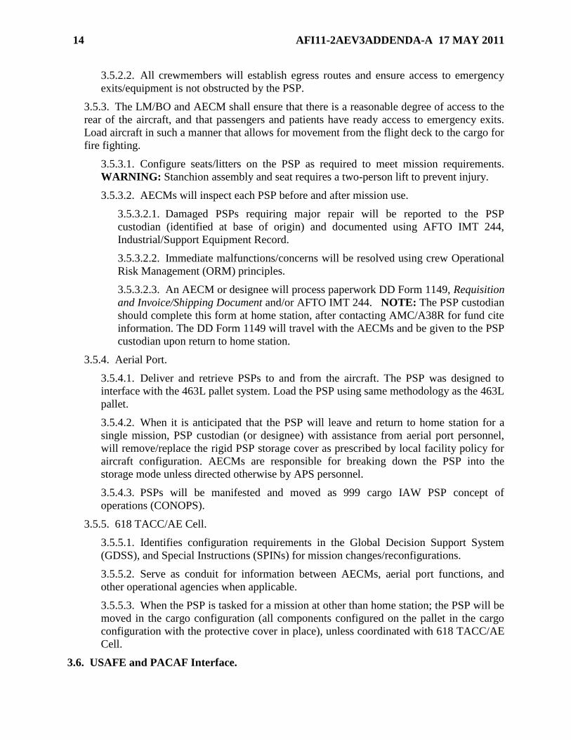
3.8.5. Place AFT stanchion assembly on pallet over the first and third seat track rails
(stanchion arms face center of pallet). Align the four seat track fittings on AFT stanchion
assembly with the RED circles on pallet. (Figure 3.6.)
Figure 3.6. AFT Stanchion Assembly.
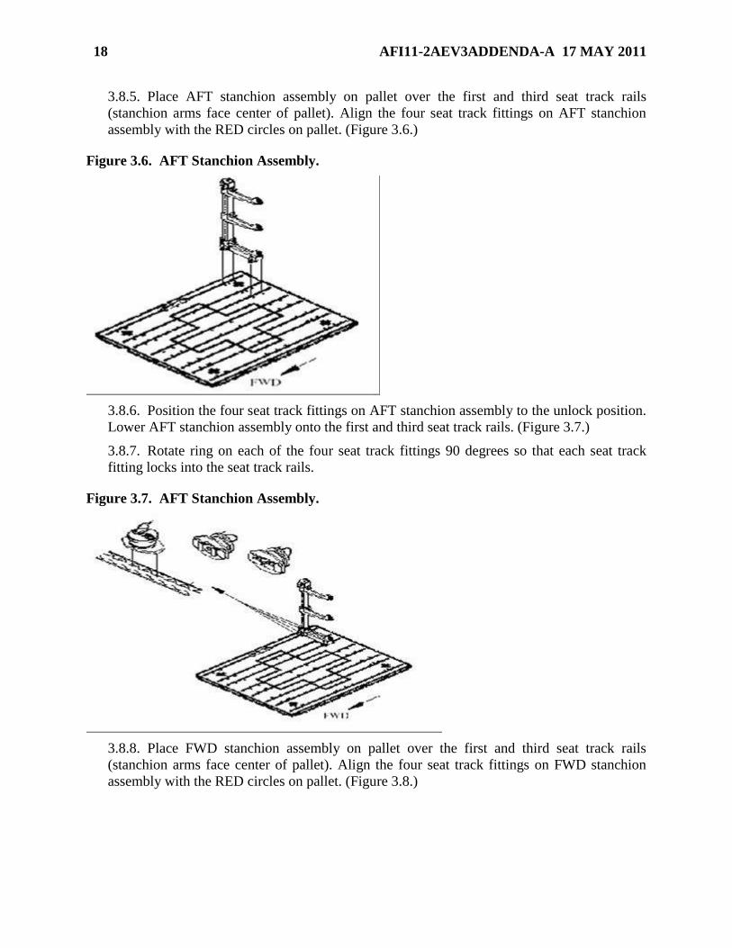
3.8.6. Position the four seat track fittings on AFT stanchion assembly to the unlock position.
Lower AFT stanchion assembly onto the first and third seat track rails. (Figure 3.7.)
3.8.7. Rotate ring on each of the four seat track fittings 90 degrees so that each seat track
fitting locks into the seat track rails.
Figure 3.7. AFT Stanchion Assembly.
3.8.8. Place FWD stanchion assembly on pallet over the first and third seat track rails
(stanchion arms face center of pallet). Align the four seat track fittings on FWD stanchion
assembly with the RED circles on pallet. (Figure 3.8.)
AFI11-2AEV3ADDENDA-A 17 MAY 2011 19
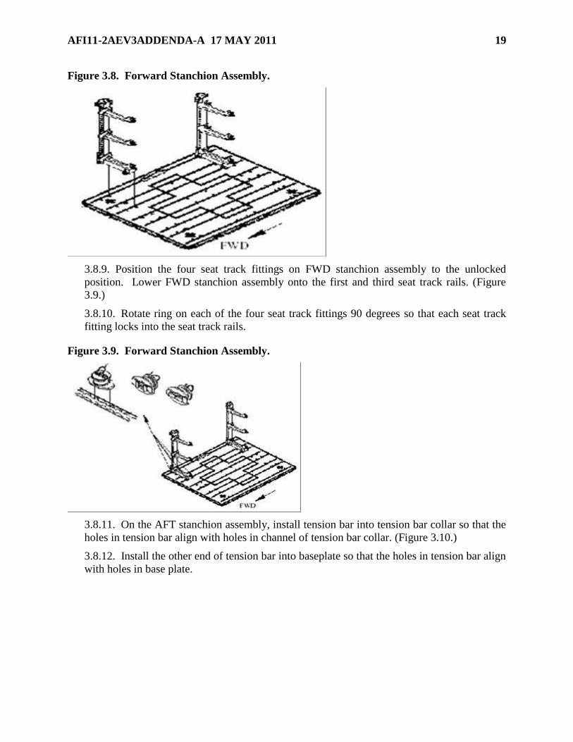
Figure 3.8. Forward Stanchion Assembly.
3.8.9. Position the four seat track fittings on FWD stanchion assembly to the unlocked
position. Lower FWD stanchion assembly onto the first and third seat track rails. (Figure
3.9.)
3.8.10. Rotate ring on each of the four seat track fittings 90 degrees so that each seat track
fitting locks into the seat track rails.
Figure 3.9. Forward Stanchion Assembly.
3.8.11. On the AFT stanchion assembly, install tension bar into tension bar collar so that the
holes in tension bar align with holes in channel of tension bar collar. (Figure 3.10.)
3.8.12. Install the other end of tension bar into baseplate so that the holes in tension bar align
with holes in base plate.
20 AFI11-2AEV3ADDENDA-A 17 MAY 2011
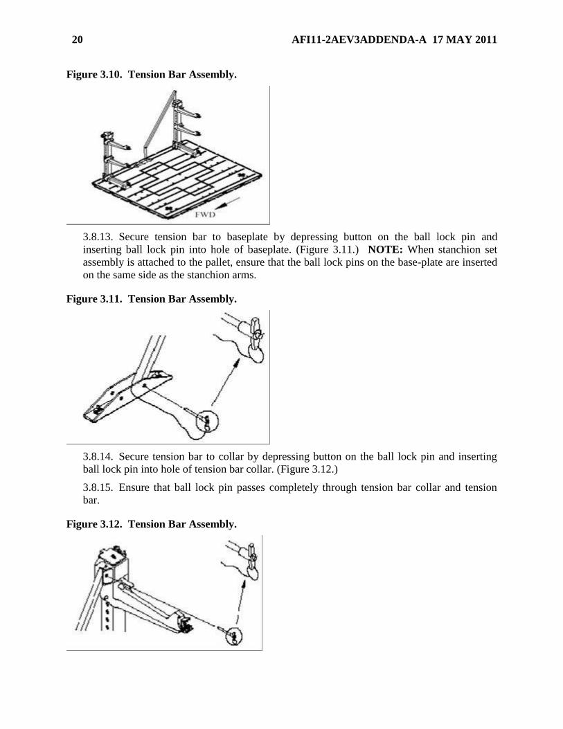
Figure 3.10. Tension Bar Assembly.
3.8.13. Secure tension bar to baseplate by depressing button on the ball lock pin and
inserting ball lock pin into hole of baseplate. (Figure 3.11.) NOTE: When stanchion set
assembly is attached to the pallet, ensure that the ball lock pins on the base-plate are inserted
on the same side as the stanchion arms.
Figure 3.11. Tension Bar Assembly.
3.8.14. Secure tension bar to collar by depressing button on the ball lock pin and inserting
ball lock pin into hole of tension bar collar. (Figure 3.12.)
3.8.15. Ensure that ball lock pin passes completely through tension bar collar and tension
bar.
Figure 3.12. Tension Bar Assembly.
AFI11-2AEV3ADDENDA-A 17 MAY 2011 21
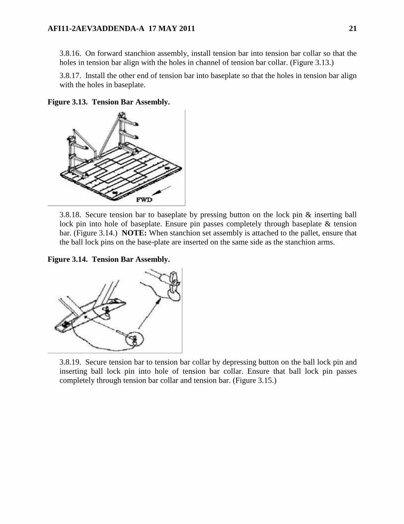
3.8.16. On forward stanchion assembly, install tension bar into tension bar collar so that the
holes in tension bar align with the holes in channel of tension bar collar. (Figure 3.13.)
3.8.17. Install the other end of tension bar into baseplate so that the holes in tension bar align
with the holes in baseplate.
Figure 3.13. Tension Bar Assembly.
3.8.18. Secure tension bar to baseplate by pressing button on the lock pin & inserting ball
lock pin into hole of baseplate. Ensure pin passes completely through baseplate & tension
bar. (Figure 3.14.) NOTE: When stanchion set assembly is attached to the pallet, ensure that
the ball lock pins on the base-plate are inserted on the same side as the stanchion arms.
Figure 3.14. Tension Bar Assembly.
3.8.19. Secure tension bar to tension bar collar by depressing button on the ball lock pin and
inserting ball lock pin into hole of tension bar collar. Ensure that ball lock pin passes
completely through tension bar collar and tension bar. (Figure 3.15.)
22 AFI11-2AEV3ADDENDA-A 17 MAY 2011
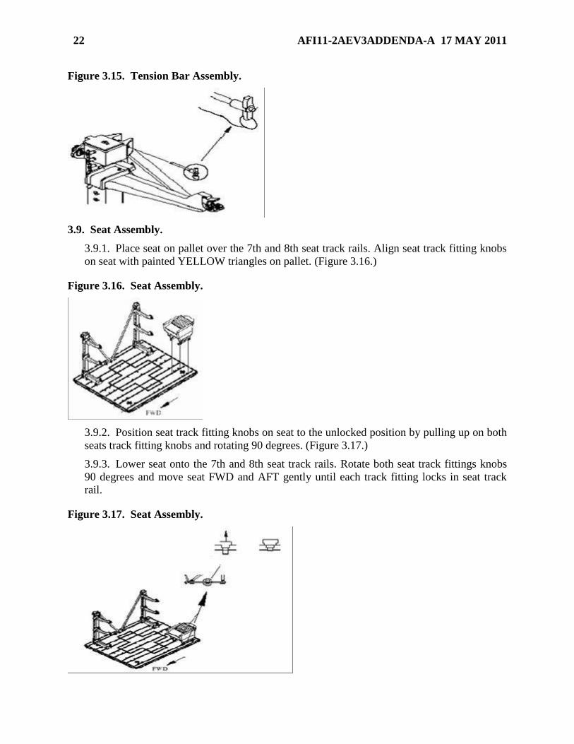
Figure 3.15. Tension Bar Assembly.
3.9. Seat Assembly.
3.9.1. Place seat on pallet over the 7th and 8th seat track rails. Align seat track fitting knobs
on seat with painted YELLOW triangles on pallet. (Figure 3.16.)
Figure 3.16. Seat Assembly.
3.9.2. Position seat track fitting knobs on seat to the unlocked position by pulling up on both
seats track fitting knobs and rotating 90 degrees. (Figure 3.17.)
3.9.3. Lower seat onto the 7th and 8th seat track rails. Rotate both seat track fittings knobs
90 degrees and move seat FWD and AFT gently until each track fitting locks in seat track
rail.
Figure 3.17. Seat Assembly.
AFI11-2AEV3ADDENDA-A 17 MAY 2011 23
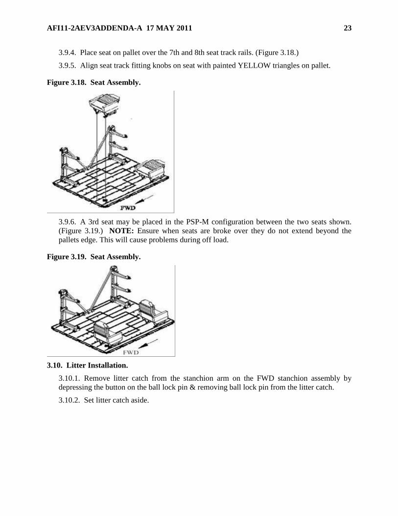
3.9.4. Place seat on pallet over the 7th and 8th seat track rails. (Figure 3.18.)
3.9.5. Align seat track fitting knobs on seat with painted YELLOW triangles on pallet.
Figure 3.18. Seat Assembly.
3.9.6. A 3rd seat may be placed in the PSP-M configuration between the two seats shown.
(Figure 3.19.) NOTE: Ensure when seats are broke over they do not extend beyond the
pallets edge. This will cause problems during off load.
Figure 3.19. Seat Assembly.
3.10. Litter Installation.
3.10.1. Remove litter catch from the stanchion arm on the FWD stanchion assembly by
depressing the button on the ball lock pin & removing ball lock pin from the litter catch.
3.10.2. Set litter catch aside.
24 AFI11-2AEV3ADDENDA-A 17 MAY 2011
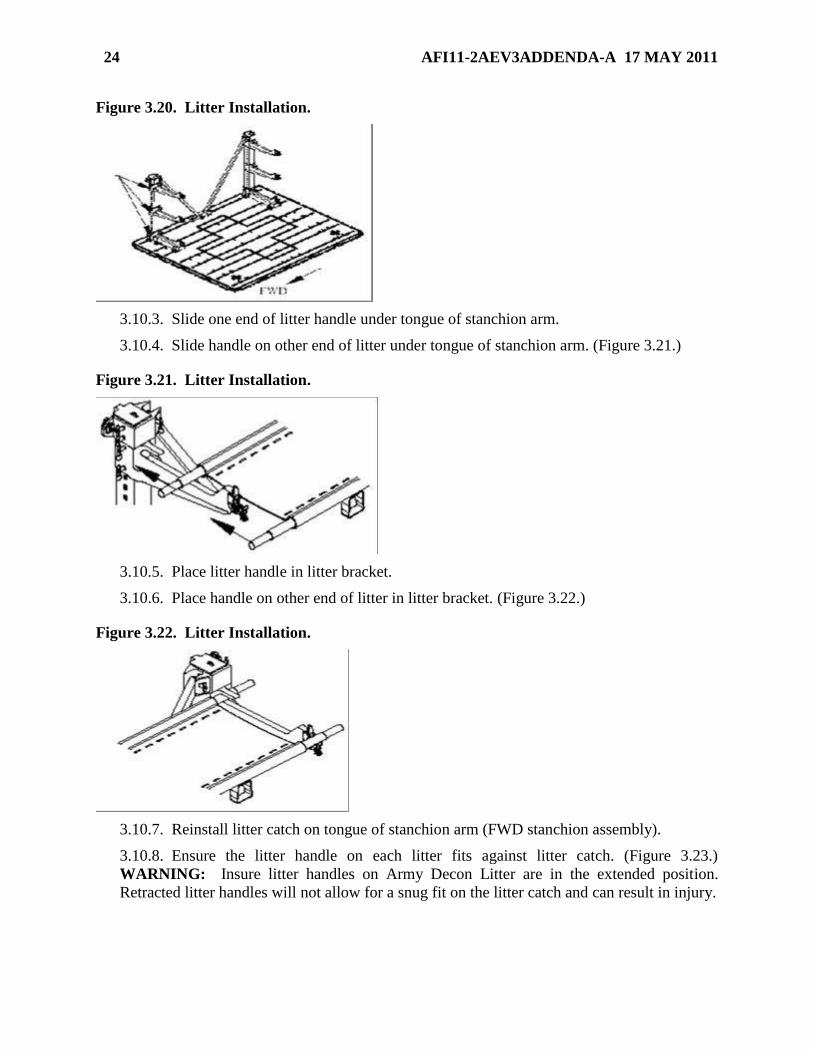
Figure 3.20. Litter Installation.
3.10.3. Slide one end of litter handle under tongue of stanchion arm.
3.10.4. Slide handle on other end of litter under tongue of stanchion arm. (Figure 3.21.)
Figure 3.21. Litter Installation.
3.10.5. Place litter handle in litter bracket.
3.10.6. Place handle on other end of litter in litter bracket. (Figure 3.22.)
Figure 3.22. Litter Installation.
3.10.7. Reinstall litter catch on tongue of stanchion arm (FWD stanchion assembly).
3.10.8. Ensure the litter handle on each litter fits against litter catch. (Figure 3.23.)
WARNING: Insure litter handles on Army Decon Litter are in the extended position.
Retracted litter handles will not allow for a snug fit on the litter catch and can result in injury.

AFI11-2AEV3ADDENDA-A 17 MAY 2011 25
Figure 3.23. Litter Installation.
3.10.9. Insert tab of locking bar in slot of lower locking assembly on both the FWD and AFT
litter brackets that contain the litter. (Figure 3.24.)
3.10.10. Ensure a snug fit on litter handle.
Figure 3.24. Litter Installation.
3.10.11. Lift up locking tab to lock litter bracket in place on litter handle. Lock litter bracket
on both the FWD and AFT litter brackets. (Figure 3.25.)
3.10.12. Ensure snug fit on litter handle.
Figure 3.25. Litter Installation.
3.11. Enplaning and Deplaning.
3.11.1. Patients and equipment will not be enplaned or deplaned on the PSP.
3.11.2. Enplane all litter patients first. Ensure seat backs are folded down during litter
enplaning/ deplaning.
26 AFI11-2AEV3ADDENDA-A 17 MAY 2011
3.11.3. Seats may be completely removed to facilitate litter/equipment loading.
3.11.4. Accomplish enplaning/deplaning of ambulatory/litter patients in the most
expeditious, safe manner. Full consideration must be given to the availability of materiel
handling equipment (MHE) and ground support personnel.
3.11.5. The KC-135/KC-10/C-17 requires a roller system to roll the PSP on and off the
aircraft. These roller systems reduce free walking space on the aircraft and present tripping
hazards in many areas. WARNING: Every effort should be made not to enplane/deplane
patients across rollers.
3.11.6. PSP ramps, extensions, and spacers should be used when available to mitigate trip
hazards created by uneven surfaces between the PSP(s) and/or the C-17 integral stanchions.
Spacers are designed to cover the gap between two pallets. The PSP ramps and extensions
attach either to the pallet or to each other to provide a smooth transition from the pallet to the
aircraft floor. EXCEPTION: On the KC-10, location of aircraft seats may prevent use of
PSP ramps immediately forward of the PSP to cover exposed rollers. In addition, PSP spacer
does not fit between pallets in Configuration I. Ensure two of the five DZUS fasteners are in
place and secured for proper ramp installation.
3.11.7. Once secured in the roller system, secure PSPs with a cargo tie down strap to the
roller system rails to prevent forward-aft pallet movement during flight. WARNING: Do
not use seat track/stanchion fitting ring(s) to secure any equipment.
3.11.8. The stanchion arms are designed for non-sequential enplaning/deplaning of
individual litter patients.
3.12. Patient Care Procedures.
3.12.1. The AECM should be cognizant of trip hazards (space between pallets, drop off on
sides of pallet, and cargo rollers) and shall provide safety briefings to patients, passengers,
attendants and litter bearers as needed. NOTE: If patient requirements dictate and
additional work space is needed, the PSP may be configured with only one litter tower. In
addition, the second tower may be installed after the patient with increased care requirements
is enplaned. WARNING: The AECM shall instruct seated patients/attendants on the
operation of the integral food tray. Improper handling of this tray may result in injury.
WARNING: Never place a litter on the bottom litter tier without securing a litter above it.
WARNING: The AECM shall be mindful of the potential strike hazard unoccupied
cantilever arms present. To eliminate the hazard: Remove cantilever arms and store in a
secure location on the aircraft, or place an empty litter in the next position. If a secure
location is unavailable, cover empty cantilever arms with blankets and secure with litter
straps.
3.13. Maintenance.
3.13.1. Keep pallets clean to protect equipment, prevent the spread of contamination, and
increase the serviceability of the unit.
3.13.2. Cleaning of pallets shall be performed when necessary and cleaning shall be
compatible with the type of material to be cleaned and the nature of the substance to be
removed. In most cases, this should be mild soap and water.
3.13.3. Keep seat track clear of any debris that will obstruct the lock engagement.
AFI11-2AEV3ADDENDA-A 17 MAY 2011 27
3.14. Disassembly and Storage. WARNING: When disassembling litter stanchions, one
person should support the weight of the stanchion as the second person unlocks and disengages
the stanchion from the seat track in the pallet floor. Failure to support the weight of the stanchion
could result in injury.
3.14.1. The stanchion assembly is stored in the horizontal position and secured to the pallet
to reduce the PSP system cubic volume during transport and storage.
3.15. KC-135 PSP CONFIGURATION.
3.15.1. Ground Configuration.
3.15.1.1. The PSP will be transported to the aircraft by aerial port personnel, positioned
and secured on the aircraft by the BO, and configured by AE personnel.
3.15.1.2. Exercise caution when maneuvering the pallet in and around the aircraft.
3.15.1.3. The BO should open the aircraft 3 hours prior to take off to facilitate AECM
aircraft configurations. The BO will coordinate with the MCD if the aircraft will not be
opened 3 hours prior to takeoff.
3.15.1.4. In cases when the KC-135 is configured at an en route stop, the MCD will
coordinate with the PIC and BO, to determine when the aircraft should be configured for
the next day’s mission. When possible, the aircraft should be configured the day prior to
the mission, before entering crew rest.
3.15.1.5. The MCD is ultimately responsible to ensure coordination between appropriate
agencies has occurred or are in place to deliver PSP(s) to the aircraft. NOTE: Each PSP
comes with only two seats. If three or six seat configuration is desired, procure one to
four additional seats from another PSP set. Each seat has storage capacity for required
prepositioned life support (EPOS and life preserver).
3.15.2. Flight Configuration.
3.15.2.1. PSP-W: Two litter tiers along the outer aspect of the pallet supporting up to
three patients per tier.
3.15.2.2. PSP-M: Three PSP seats and one litter tier along the outer aspect of the pallet
supporting up to three litter and three ambulatory patients. During an inflight medical
emergency, seats can be removed and placed off to the side to increase working space.
NOTE: Each seat weighs 65 LBS. Combinations of one to three seats may be carried on
the PSP-M.
3.15.2.3. PSP-S: Six PSP seats supporting up to six ambulatory patients, medical
attendants or crewmembers.
3.15.2.4. Each litter position is rated to hold 320 lbs. Each seat is rated to hold 260 lbs.
WARNING: On the KC-135, maximum PSP total load (PSP plus patients/equipment)
will not exceed 2000 lbs. This includes the weight of the PSP. If weight is exceeded,
supplemental restraint is required. Restrain PSP to 9 Gs forward. Use T.O. 1C-135-9
when applying supplemental restraint.
3.15.2.5. During preflight, the Charge Medical Technician (CMT) will estimate
equipment/IFK weights IAW the abbreviated checklist and provide weights per

28 AFI11-2AEV3ADDENDA-A 17 MAY 2011
pallet/floor load station to the BO. NOTE: When possible, configure the PSP seats to
face aft.
3.15.3. AE-1. One PSP positioned in the number one pallet position, station 504 centroid.
All possible omni rollers should be removed for minimal roller exposure. Utilize PSP-M with
litters on the (R) side of the aircraft or PSP-S in pallet position 1 only. Maximum litter spaces
available are three. Airline type seating if required may accommodate 16 ambulatory
patients. The (L) aircraft side aisle-way should be kept clear of all obstacles at all times,
allowing access to the lavoratory.
3.15.4. AE-2. Two PSPs in pallet position 1 & 2, stations 504, and 624 centroid respectively.
May utilize PSP-M, PSP-W or PSP-S in pallet position 2. Maximum litter spaces available
are nine. Airline type seating if required may accommodate 16 ambulatory patients. The (L)
aircraft side aisle-way should be kept clear of all obstacles at all times, allowing access to the
lavoratory.
3.15.5. AE-3. Three PSPs placed in pallet position 1, 2, and 3, stations 504, 624, and 774
centroid respectively. May utilize PSP-M, PSP-W or PSP-S in pallet position 3. Maximum
litter spaces available are 15. Airline seating if required will accommodate 8 ambulatory
patients. Hardware (four extensions and two ramps) should be placed to cover the exposed
rollers at the (R) overwing hatch. Attach two extensions to each pallet and cover remaining
gap with ramps. NOTE: If pallet #2 and #3 are not correctly placed, additional hardware
will not fit correctly. The forward edge of pallet #3 must be positioned at station 720. If
sufficient hardware is not available, consult the BO for an alternate means to cover the
rollers. i.e. Utilize plywood secured over the rollers.
3.15.6. Ambulatory. Airline type seats should be used for seating ambulatory patients versus
PAX or crewmembers. Aft Facing Stud Mounted seats and PSP seats are the only approved
seats for use on the KC-135. Airline seats will be floor mounted to avoid tripping hazards
associated with uneven floors with pallets.
3.15.6.1. Do not use palletized seats.
3.15.6.2. Aircraft should depart home station with airline seats installed.
3.15.6.3. If seat sets are positioned over the main landing gear lock inspection windows
(station 900), ensure the inspection windows are opened prior to seat installation.
3.15.6.4. Ambulatory patients may be seated in the troop seats at the MCDs discretion.
3.15.7. Baggage Bins. The aircraft will leave home station with two baggage bins. Any
equipment placed forward of the auxiliary power unit (APU) will be repositioned aft of the
aft hatch or inside the baggage bins. Bins will be placed as far aft as possible without
blocking access to APU fire access panels. Side load bins to the maximum extent possible to
provide improved aisle space for patient movement.
3.15.7.1. With assistance from the BO; pre-configured tie down equipment and life rafts
may need to be repositioned.
3.15.7.2. A clear egress route will be maintained from the crew compartment to the aft
emergency escape hatch. Excess AE equipment (inflight kits) may be positioned aft of
the seats or forward of the baggage bins. Placing non-critical equipment and supplies in

AFI11-2AEV3ADDENDA-A 17 MAY 2011 29
this location increases space near patients and does not limit egress out the aft emergency
escape hatch.
3.15.7.3. Coordinate with the BO prior to securing excess AE equipment and in-flight
kits.
3.15.7.4. Pallet end stops protrude into egress paths. Remove front and aft pallet end
stops once PSPs are locked in place. The BO will reinstall pallet end stops prior to
unlocking PSPs.
3.15.7.5. The BO will ensure the roller system is properly configured prior to unlocking
the pallets during unloading operations.
3.16. C-17 PSP CONFIGURATION.
3.16.1. Use C3 configuration AFI 11-2C-17 Volume 3, Addenda A, C-17 Configuration and
Mission Planning as reference for PSP loading. C3 configuration places pallets in the logistic
rails side-by-side in the aircraft. Each side-by-side configuration is considered one pallet
position. To follow are PSP pallet position specifics:
3.16.2. Pallet position L1/R1 are not authorized for the PSP litter configurations, but can be
used for the comfort pallet and/or 6-12 PSP seats. Seats should be used by flight crew,
Critical Care Aeromedical Evacuation Transport Team (CCATT) and aeromedical crew
members (AECMs). WARNING: PSPs will not be loaded in the ADS rails; sideways litter
patient orientation is not authorized.
3.16.3. PSP(s) can be placed in pallet positions L2/R2 to L6/R6, for a maximum of 12
PSP(S). Pallet positions L2/R2 through L5/R5 can hold 6-8 patients per pallet. Pallet
positions L6/R6 can hold up to three ambulatory and 3-4 litters per pallet. Total number of
litters that can be carried is 54-72 litters. Maximum litter load is dependent on whether
patients are loaded three or four high.
3.16.4. Pallet position L7/R7 is only authorized for the PSP-S. For egress purposes, only the
three seats on the inside track of the pallet will be used for patients, flight crew, CCATT
and/or AECMs.
3.16.5. Pallet positions L8/R8 and L9/R9 are not authorized for PSP use. Extra medical
equipment and baggage may be tied down in this area.
3.16.6. A combination of PSP(s) and the three C-17 integral stanchions can be used. A
maximum of 9 PSP(s) can be used with the three integral stanchions for a max litter load of
45-57. Maximum litter load is dependent on whether PSP patients are loaded three or four
high.
3.17. PSP Inventory.
3.17.1. 463L Pallet intact and functional
3.17.2. Brackets available and operable
3.17.3. Ramps available and operable
3.17.4. Spacers available and operable
3.17.5. Extenders available and operable

30 AFI11-2AEV3ADDENDA-A 17 MAY 2011
3.17.6. Litter stanchions available and functional
3.17.7. Seats available, clean, and operable
3.18. PSP Spare Parts Repair Kit.
3.18.1. 4 Wire Bolts (P/N 9489T45)
3.18.2. 4 Machine Bolts (P/N AN3-15A)
3.18.3. 2 Bracket Assemblies (litter clamps) (P/N FDC-3835-31)
3.18.4. 4 Nuts (P/N MS21042L3)
3.18.5. 8 Washers (P/N NAS1149D0332J)
3.18.6. 2 Pin Assemblies 7/16 X 5 inch (P/N A7803144500-001)
3.18.7. 2 Pin Assemblies 7/16 X 3 inch (P/N A7803144500-002)
3.18.8. 2 Pin Assemblies 3/16 X 2 inch (P/N A7803144500-003)
3.18.9. 1 Fitting-Quick Disconnect (P/N A7100)
3.18.10. 1 Container to contain the above
3.19. PSP Inspection.
3.19.1. 1. Annotate any mission/broken parts on AFTO IMT 244
3.19.2. 2. Replace/repair broken parts with spare parts kits if able
3.19.3. 3. Ensure ramp and spacers are in place; release lever is equipped with spring
3.19.4. 4. Ensure installed ramps have 2 of 5 operable DZUS fasteners. NOTE: to prevent
slight forward movement, secure the PSP w/5000 lb cargo tie down strap
3.19.5. 5. Ensure tension bars are secured to base plate and locked
3.19.6. 6. Ensure litter stanchion poles and base plate are locked and secured to the PSP
3.19.7. 7. All ball lock pins are inserted on the same side of stanchion arms
3.19.8. 8. Ensure litter catches are installed on forward end of each occupied litter
3.19.9. 9. Seats will be aligned with proper markings and locked in upright position
3.19.10. 10. Check seat belts, reclining action & tray table for operation
3.19.11. 11. Ensure each seat has an EPOS & LPU. Annotate inspection date and any
discrepancies on the AFTO IMT 244.
3.20. Litter Station Augmentation Set (LSAS).
3.20.1. Litter Station Augmentation Set (LSAS). A C-17 LSAS has nine litter stations (18
stanchions, 18 struts and 9 utility panels) and spare parts (one pair of additional struts,
additional stanchion, and additional utility panel) providing 27 additional litter capabilities.
3.20.2. The intended use of the C-17 LSAS is for large patient loads that exceed the
aircraft’s organic litter carrying capability. Although a mission may not require a full 36 litter
positions, the LSAS is a kit and the full complement of components (in storage box) will be
transported on the mission. This ensures that the equipment set is kept together for all stages

AFI11-2AEV3ADDENDA-A 17 MAY 2011 31
of employment and allows repositioning movement of the C-17 LSAS as designated by the
airlift-tasking agency.
3.20.3. Custodial Duties.
3.20.3.1. Each C-17 LSAS will be considered a kit and an inventory will be included.
The custodian will ensure that each C-17 LSAS is inventoried upon receipt, and
before/after each mission.
3.20.3.2. The custodian will prepare a DD Form 1149, Requisition and Invoice/Shipping
Document, provide it to the Charge Medical Technician for the AE mission, and include
it with any LSAS being used for an AE mission. The DD Form 1149 is used by the
AECM, Aeromedical Evacuation Operations Officer (AEOO), or AE ground support
personnel to initiate return shipment of the LSAS when it’s left at a station other than the
origination.
3.20.4. LSAS Tasking. The airlift-tasking agency, Tanker Airlift Control Center (TACC),
USAFE/ PACAF Warfighting Headquarters (WFHQ), or Air Mobility Division
(AMD)/Aeromedical Evacuation Control Team (AECT) is responsible for tasking the LSAS
for use when required. If the LSAS is needed for an AE mission at a location other than
where it is assigned, TACC, USAFE/PACAF WFHQ, or AECT will task and position the
LSAS to the location required for the mission, using opportune airlift or the Traffic
Management (TMO) system. The C-2 agency may consider tasking an AEOO to accompany
the C-17 LSAS when it will terminate at a location other than point of origination. The C-2
agency may also determine that a crew duty time/flight duty period waiver may be necessary
to facilitate getting the LSAS properly processed through TMO for return shipment.
3.20.4.1. When the LSAS is employed for an AE mission, care and management of the
LSAS is transferred from the custodian to AE personnel until the time it is inserted into
the TMO system for return shipment.
3.20.4.2. LSAS Positioning. If an LSAS is required for an operational AE mission, the
storage box will normally be loaded on the aircraft ramp in the aerial delivery system
(ADS) rails IAW T.O. 1C-17A-9 (Position 10 or 11).
3.20.4.3. If a full complement of litters is not required, the LSAS may be positioned in
any ADS (Center Row) pallet position. This positioning is intended to maximize the C-17
litter capacity and facilitates aircraft evacuation paths on both sides of the aircraft.
3.20.4.4. The LSAS will not be positioned in the logistic rail system at any time during
patient loading/offloading or during flights with patients on board the aircraft. This is to
ensure adequate egress paths are maintained IAW T.O. 1C-17A-1.
3.20.4.5. Should a LSAS storage box be transported as cargo with no patients on board
the aircraft, the container may be positioned in any pallet position using either rail system
IAW T.O. 1C-17A-9.
3.20.5. Mission Execution. The MCD will develop a load plan based on patient
requirements. The AE crew will receive the LSAS equipment at the aircraft from the LSAS
custodial Ramp Services/Aerial Port Squadron (APS) personnel and inspect the LSAS for
damage prior to use. The AE crew will configure the aircraft IAW the load plan using the
aircraft's integral organic litter station components and those provided in the C-17 LSAS.

32 AFI11-2AEV3ADDENDA-A 17 MAY 2011
3.20.6. Patient Loading/Offloading. The LSAS will remain onboard the aircraft during
patient loading/offloading. EXCEPTION: In the rare event that a specific patient’s
condition, equipment needs or size raises serious safety concerns, the LSAS box may be
removed from the aircraft for increased clearance. The PIC with coordination between the
MCD and LM is the final authority in determining if the LSAS should be removed to
facilitate patient on/offloading. The MCD will request ground handling equipment, as
required, on the off-load message. WARNING: During loading/off loading, pay attention
to the elevated area around the edge of the LSAS. (This area could be a potential tripping
hazard). Spotter(s) should be used to ensure litter bearers are aware of the hazard. When
on/offloading patients of excessive weight or with excessive equipment requiring more than a
four-person carry, extra caution should also be used.
3.20.7. Mission termination. AECMs, Loadmasters, AEOOs, AE ground support and/or
flight line personnel will deconfigure the LSAS as required for storage/shipping. AECMs
will tag damaged components, which must be placed back in the LSAS storage box with
AFTO Form 350, and also document the deficiency on the AFTO Form 244. If LSAS
terminates at another location than its origin, the AECMS, AEOOs, AE ground support will
ensure the LSAS DD Form 1149 is processed through the local TMO (as described in
paragraph 5.6.2.2.) NOTE: AECMs will ensure that aircraft equipment affixed with unit
identification remain with the aircraft. Mixing of specially identified aircraft equipment and
LSAS parts is prohibited.
3.20.7.1. The Medical Crew Director (MCD) will call the 24-hour contact AE cell at
their airlift control agency to report on the mission. For PACAF/USAFE missions,
WFHQ or AECT will phone patch-in TACC for mission termination report. This report
will include information regarding disposition of the LSAS. Specifically, the MCD will
report the on-load/off-load International Civil Aviation Organization (ICAO) code of the
LSAS, equipment identification number, Transportation Control Number (TCN) and
describe damaged equipment which was tagged using AFTO Form 350, Repairable Item
Processing Tag.
3.20.7.2. At enroute locations, reconfiguration and/or removal of LSAS components is
not authorized unless coordinated with TACC/XOPA.
3.20.8. LSAS Tracking/Repositioning. In most cases, the LSAS will return to the originating
location on the mission on which it was flown. If an AE mission terminates at a location
other than origin, the LSAS will be processed through the TMO as cargo. It is necessary that
AE crew, AEOO, and AE ground support personnel are familiar with the DD Form 1149 so
they may process it and the LSAS kit at the mission termination TMO location.
3.20.8.1. The AECM or AE ground support personnel will obtain a TCN from TMO and
convey this information to the AE C2 during end of mission report.
3.20.8.2. APS personnel unload aircraft and take cargo to the marshalling yard or TMO
for processing. With APS assistance the AECM or AE ground support personnel will
process the DD Form 1149 for shipment of the LSAS to the owning unit.
3.20.8.3. The tasking agency will serve as a conduit for information between AECMs,
aerial port functions, and other operational agencies when applicable.
3.20.9. Maintenance.

AFI11-2AEV3ADDENDA-A 17 MAY 2011 33
3.20.9.1. Minor Repairs. At home station, the C-17 LSAS custodian will accomplish
minor repairs if possible. Other than the utility panel, the LSAS components are stamped
steel, and will not have a minor maintenance requirement.
3.20.9.2. Major Repairs. At mission termination, the AE crews will coordinate with the
Load-master to swap damaged LSAS components with functional components from the
aircraft' s organic complement of three litter stations. This ensures that the C-17 LSASs
are kept in fully mission ready status. However, the aircraft complement of litter stations
should not be totally decimated; at least one fully functional litter station should remain
on the aircraft. If broken litter station parts are swapped with the aircraft's organic
complement of litter stations, the Loadmaster will annotate the defects on the AFTO
Form 781A, Maintenance Discrepancy and Work Document, to ensure aircraft
component repair.
3.20.9.3. Spare Parts. The spare parts that will be contained in the C-17 LSAS are one
pair of additional struts, one additional stanchion, and one additional utility panel. The
custodian will ensure that spare parts are present in the storage box and functional.
34 AFI11-2AEV3ADDENDA-A 17 MAY 2011
Chapter 4
C130 E, H, J CONFIGURATIONS
4.1. Aircraft Systems.
4.1.1. Oxygen.
4.1.1.1. Therapeutic oxygen. Not available on the C-130 or C-130J. Utilize the PTLOX
or compressed oxygen tanks as available.
4.1.1.2. Patient emergency oxygen. Utilize EPOS.
4.1.1.3. Crew oxygen. One 25L LOX bottle is located in nose of aircraft which is used
to supply emergency oxygen to pressure demand regulators and recharger hoses.
4.1.2. Electrical.
4.1.2.1. Electrical power is provided through either the Galley or Missile Support System
cannon plugs. Each outlet will provide 20 amps for an aircraft total of 100 amps.
4.1.2.2. Medical equipment rated at 115 Volt/400 Hz can be operated from either the
Galley or Missile Support System utilizing an approved C-130 pigtail adaptor located in
the Electrical Cord Assembly Set (ECAS).
4.1.2.3. Utilize the Avionics/Unitron Frequency Converter through the Missile Support
System for medical equipment rated at 115Volt/60 Hz.
4.1.2.4. On the C-130 J aircraft, six 3-pin "household type" service outlets can be used
with AE equipment that operates on 115 Volt/400 Hz. Each outlet will provide 15 amps
for a total of 90 amps.
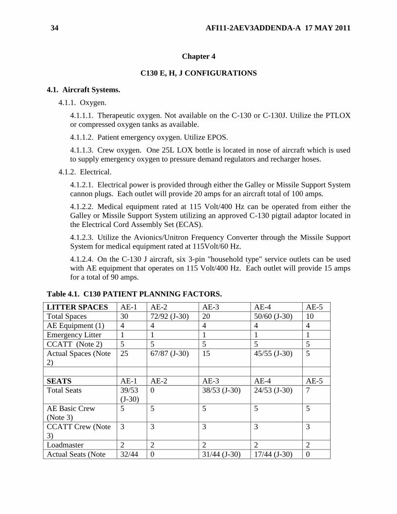
Table 4.1. C130 PATIENT PLANNING FACTORS.
LITTER SPACES AE-1 AE-2 AE-3 AE-4 AE-5
Total Spaces 30 72/92 (J-30) 20 50/60 (J-30) 10
AE Equipment (1) 4 4 4 4 4
Emergency Litter 1 1 1 1 1
CCATT (Note 2) 5 5 5 5 5
Actual Spaces (Note
2)
25 67/87 (J-30) 15 45/55 (J-30) 5
SEATS AE-1 AE-2 AE-3 AE-4 AE-5
Total Seats 39/53
(J-30)
0 38/53 (J-30) 24/53 (J-30) 7
AE Basic Crew
(Note 3)
5 5 5 5 5
CCATT Crew (Note
3)
3 3 3 3 3
Loadmaster 2 2 2 2 2
Actual Seats (Note 32/44 0 31/44 (J-30) 17/44 (J-30) 0

AFI11-2AEV3ADDENDA-A 17 MAY 2011 35
4) (J-30)
NOTES:
1. Additional equipment/bags will be floor loaded unless space is available in litter tiers.
2. Actual litter spaces may decrease based upon patient requirements and equipment.
An emergency litter will be carried on all AE missions. CCATT vented patients require
one litter tier (5 litter spaces). Non-vented CCATT patients do not require a litter tier
unless equipment prohibits loading of additional patients in the same litter tier.
3. AE and CCATT seats are based on primary crew compliment.
4. Actual seats may decrease based on crew compliment, mission requirements and
patient load.
Figure 4.1. AE-1.
Figure 4.2. AE-2.
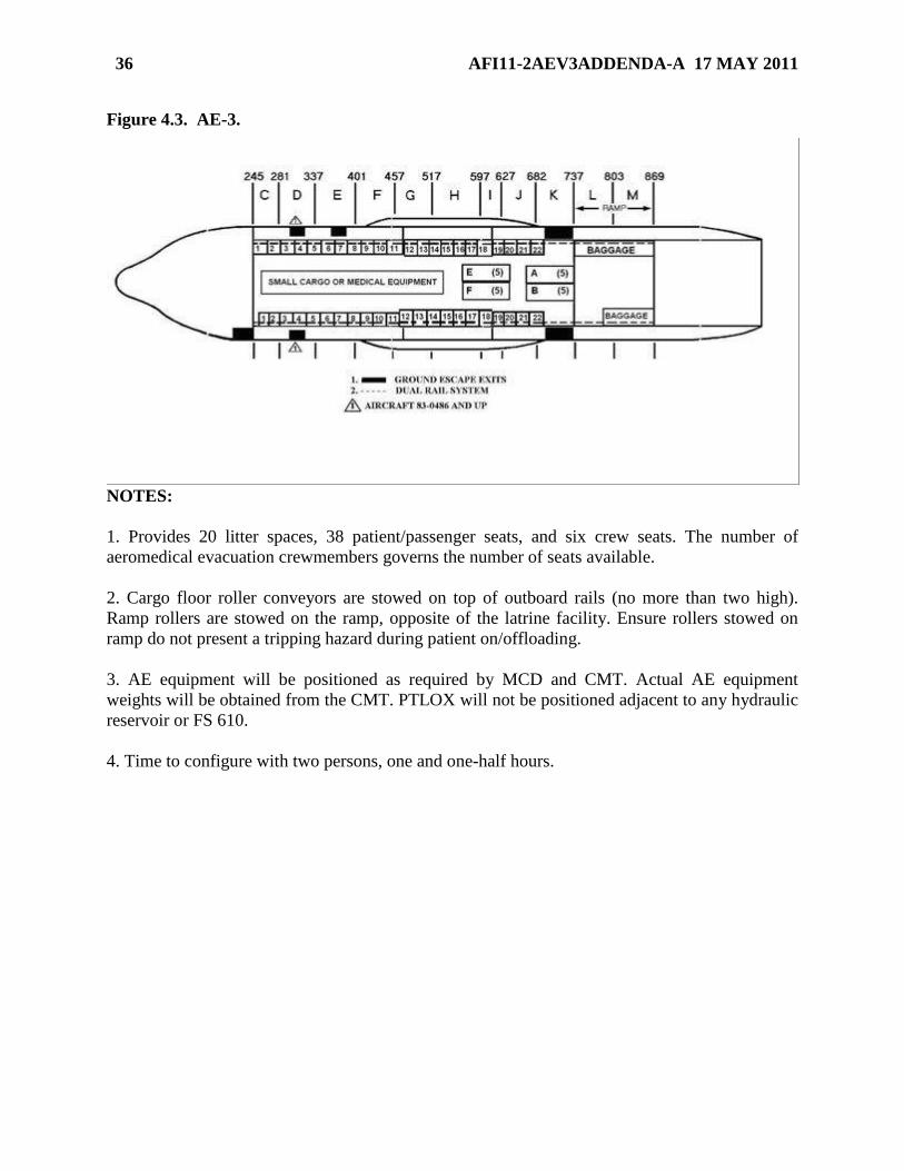
36 AFI11-2AEV3ADDENDA-A 17 MAY 2011
Figure 4.3. AE-3.
NOTES:
1. Provides 20 litter spaces, 38 patient/passenger seats, and six crew seats. The number of
aeromedical evacuation crewmembers governs the number of seats available.
2. Cargo floor roller conveyors are stowed on top of outboard rails (no more than two high).
Ramp rollers are stowed on the ramp, opposite of the latrine facility. Ensure rollers stowed on
ramp do not present a tripping hazard during patient on/offloading.
3. AE equipment will be positioned as required by MCD and CMT. Actual AE equipment
weights will be obtained from the CMT. PTLOX will not be positioned adjacent to any hydraulic
reservoir or FS 610.
4. Time to configure with two persons, one and one-half hours.

AFI11-2AEV3ADDENDA-A 17 MAY 2011 37
Figure 4.4. AE-4.
NOTES:
1. Combat/contingency configuration provides 50 litter spaces, 24 patient/passenger, and six
crew seats. The number of aeromedical evacuation crewmembers governs the number of seats
available.
2. Cargo floor roller conveyors are stowed on top of outboard rails (no more than two high).
Ramp rollers are stowed on the ramp, opposite of the latrine facility. Ensure rollers stowed on
ramp do not present a tripping hazard during patient on/offloading.
3. AE equipment will be positioned as required by MCD and CMT. Actual AE equipment
weights will be obtained from the CMT. PTLOX will not be positioned adjacent to any hydraulic
reservoir or FS 610.
4. Time to configure with two persons, two hours.

38 AFI11-2AEV3ADDENDA-A 17 MAY 2011
Figure 4.5. AE-5.
NOTES:
1. This is a variation to the AE-4 combat/contingency configuration and provides 10 litter
spaces, 24 palletized trip seats, and 7 sidewall seats. The number of aeromedical evacuation
crewmembers governs the number of seats available.
2. Cargo floor roller conveyors not used and ramp roller conveyors are stowed on top of
outboard rails forward of FS 617 (not more than two high).
3. AE equipment will be positioned as required by the MCD. PTLOX will not be positioned
adjacent to any hydraulic reservoir or FS 610.
4. Time to configure with one person, one hour.
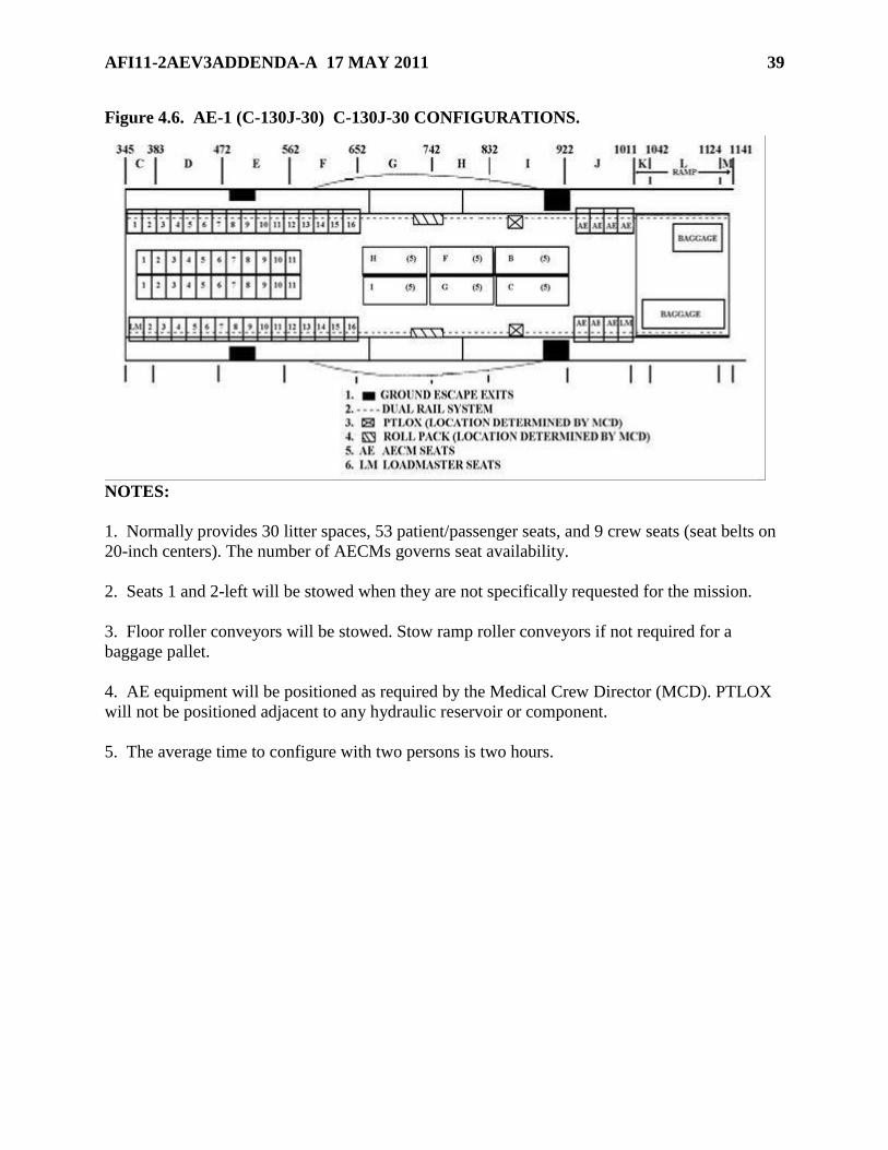
AFI11-2AEV3ADDENDA-A 17 MAY 2011 39
Figure 4.6. AE-1 (C-130J-30) C-130J-30 CONFIGURATIONS.
NOTES:
1. Normally provides 30 litter spaces, 53 patient/passenger seats, and 9 crew seats (seat belts on
20-inch centers). The number of AECMs governs seat availability.
2. Seats 1 and 2-left will be stowed when they are not specifically requested for the mission.
3. Floor roller conveyors will be stowed. Stow ramp roller conveyors if not required for a
baggage pallet.
4. AE equipment will be positioned as required by the Medical Crew Director (MCD). PTLOX
will not be positioned adjacent to any hydraulic reservoir or component.
5. The average time to configure with two persons is two hours.

40 AFI11-2AEV3ADDENDA-A 17 MAY 2011
Figure 4.7. AE-2 (C-130J-30).
NOTES:
1. Normally provides 97 litter spaces and ten crew seats. The number of AECMs governs the
number of litters available. Additional aircraft equipment may reduce the number of available
litter spaces.
2. Floor roller conveyors will be stowed. Stow ramp roller conveyors if not required for a
baggage pallet.
3. Wheel well seats, if used, will be installed and hooked up to the seat-back support bar.
AECMs will complete final seat installation. NOTE: Paratroop door observer seat (some aircraft)
must be removed from the doors to allow opening/closing of the doors when the paratroop door
litter stanchions are installed.
4. AE equipment will be positioned as required by the MCD. PTLOX will not be positioned
adjacent to any hydraulic reservoir or component.
5. The average time to configure with two persons is 2-1/2 hours.
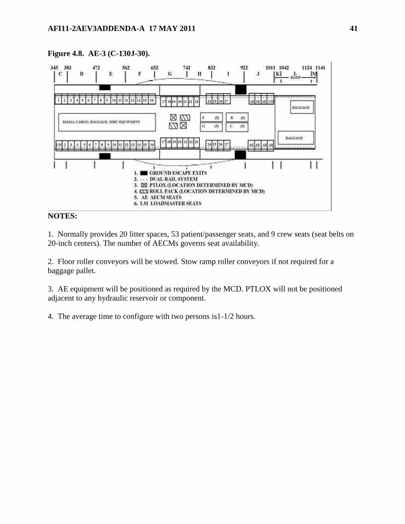
AFI11-2AEV3ADDENDA-A 17 MAY 2011 41
Figure 4.8. AE-3 (C-130J-30).
NOTES:
1. Normally provides 20 litter spaces, 53 patient/passenger seats, and 9 crew seats (seat belts on
20-inch centers). The number of AECMs governs seat availability.
2. Floor roller conveyors will be stowed. Stow ramp roller conveyors if not required for a
baggage pallet.
3. AE equipment will be positioned as required by the MCD. PTLOX will not be positioned
adjacent to any hydraulic reservoir or component.
4. The average time to configure with two persons is1-1/2 hours.
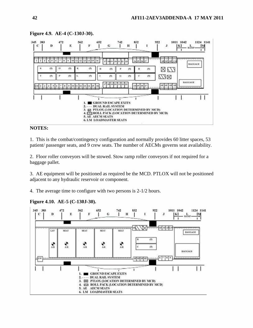
42 AFI11-2AEV3ADDENDA-A 17 MAY 2011
Figure 4.9. AE-4 (C-130J-30).
NOTES:
1. This is the combat/contingency configuration and normally provides 60 litter spaces, 53
patient/ passenger seats, and 9 crew seats. The number of AECMs governs seat availability.
2. Floor roller conveyors will be stowed. Stow ramp roller conveyors if not required for a
baggage pallet.
3. AE equipment will be positioned as required be the MCD. PTLOX will not be positioned
adjacent to any hydraulic reservoir or component.
4. The average time to configure with two persons is 2-1/2 hours.
Figure 4.10. AE-5 (C-130J-30).
AFI11-2AEV3ADDENDA-A 17 MAY 2011 43
NOTES:
1. Due to the non-availability of seat pallets and comfort pallets at most C-130 bases, load
planners and users must coordinate for these items when requesting this configuration. This is a
variation to the AE-4 combat/contingency configuration and provides 10 litter spaces, 32
palletized trip seats, 4 patient/passenger sidewall seats, and 9 crew seats. The number of AECMs
governs seat availability.
2. Floor roller conveyors will be stowed. Stow ramp roller conveyors if not required for a
baggage pallet.
AE equipment will be positioned as required by the MCD. PTLOX will not be positioned
adjacent to any hydraulic reservoir or component.
3. The average time to configure with one person is 1-1/2 hours.

44 AFI11-2AEV3ADDENDA-A 17 MAY 2011
Chapter 5
C-17 PATIENT PLANNING FACTORS
5.1. Aircraft Systems.
5.1.1. Oxygen.
5.1.1.1. Therapeutic oxygen. A minimum quantity of 75 liters of LOX is required for
scheduled aeromedical evacuation missions originating from staged/home station. At en
route stops, the MCD in conjunction with the PIC will ensure the total LOX quantity is
sufficient to meet all anticipated patient needs. EXCEPTION: For In System Select
(ISS) aircraft or AE alert missions, the MCD in conjunction with the PIC will ensure the
total LOX quantity is sufficient to complete the mission. The MCD will notify C2 of
LOX quantity limitation. NOTE: Provisions must also be available for an emergency
oxygen source if five ventilated patients will be transported.
5.1.1.2. Patient emergency oxygen. Ambulatory and litter patients will utilize the
passenger emergency oxygen system. NOTE: Floor-loaded patients or patients
positioned on PSPs will be provided EPOS. NOTE: Backrest position could obstruct
the oxygen panels and mask containers of patients placed in litter tier positions. Ensure a
mask is accessible to each litter patient.
5.1.1.3. Crew Oxygen. One 25L LOX bottle is used to supply emergency oxygen to
pressure demand regulators and recharger hoses on the flight deck. Two 75L LOX bottles
supply oxygen to pressure demand regulators, recharger hoses, passenger emergency
oxygen, and patient therapeutic oxygen in the cargo compartment.
5.1.2. Electrical.
5.1.2.1. A primary 115V/60 Hz converter is installed on-board the C-17 which provides
60 Hz electrical power to the six aeromedical electrical outlet panels. There are two 115
VAC/60 Hz outlets on each panel.
5.1.2.1.1. Do not exceed 30 amps total to the 60 Hz system (This includes all 60 Hz
outlets on the six aeromedical electrical outlet panels).
5.1.2.1.2. To increase C-17 electrical amp capability, a Avionics/Unitron Frequency
converter may be plugged directly into one of the 115-200V/400 Hz AC outlets
located on the six aeromedical electrical outlet panels. Do not exceed 20 amps per
aircraft left side and 20 amps per aircraft right side to the 400 Hz system for a total of
40 amps when using the Avionics/Unitron Frequency converter.
Table 5.1. Patient Planning Factors.
LITTER SPACES AE-1 AE-2 AE-3 AE CL-4
Total Spaces 9 36 9 6
AE Equipment Floor Load 4 4 2
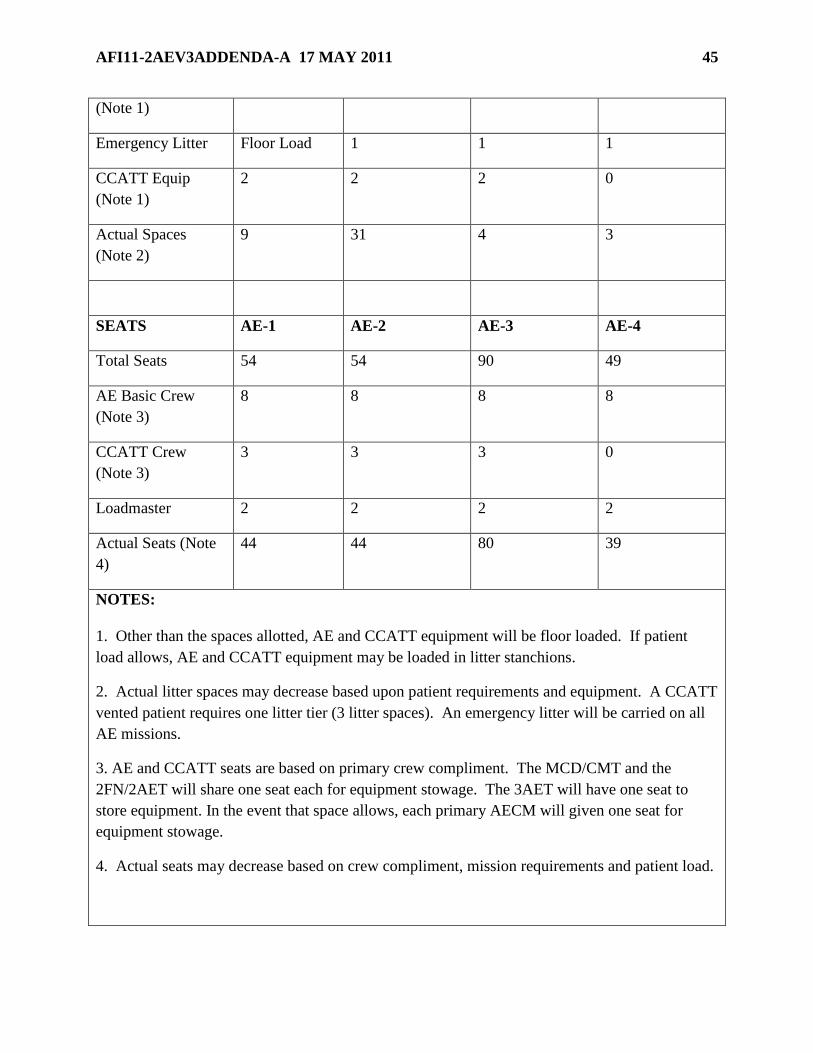
AFI11-2AEV3ADDENDA-A 17 MAY 2011 45
(Note 1)
Emergency Litter Floor Load 1 1 1
CCATT Equip
(Note 1)
2 2 2 0
Actual Spaces
(Note 2)
9 31 4 3
SEATS AE-1 AE-2 AE-3 AE-4
Total Seats 54 54 90 49
AE Basic Crew
(Note 3)
8 8 8 8
CCATT Crew
(Note 3)
3 3 3 0
Loadmaster 2 2 2 2
Actual Seats (Note
4)
44 44 80 39
NOTES:
1. Other than the spaces allotted, AE and CCATT equipment will be floor loaded. If patient
load allows, AE and CCATT equipment may be loaded in litter stanchions.
2. Actual litter spaces may decrease based upon patient requirements and equipment. A CCATT
vented patient requires one litter tier (3 litter spaces). An emergency litter will be carried on all
AE missions.
3. AE and CCATT seats are based on primary crew compliment. The MCD/CMT and the
2FN/2AET will share one seat each for equipment stowage. The 3AET will have one seat to
store equipment. In the event that space allows, each primary AECM will given one seat for
equipment stowage.
4. Actual seats may decrease based on crew compliment, mission requirements and patient load.
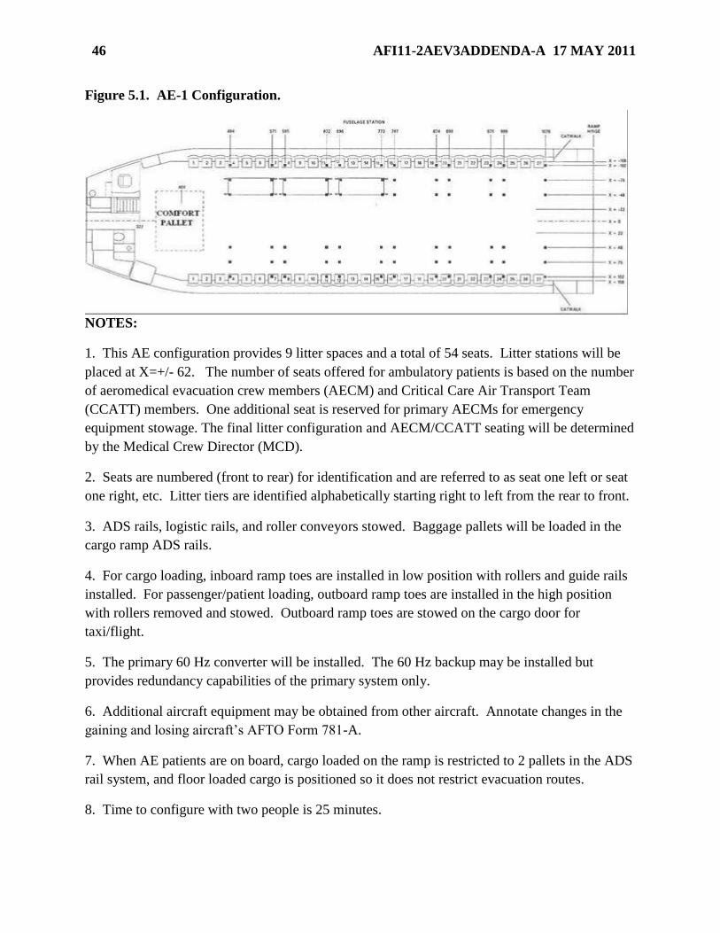
46 AFI11-2AEV3ADDENDA-A 17 MAY 2011
Figure 5.1. AE-1 Configuration.
NOTES:
1. This AE configuration provides 9 litter spaces and a total of 54 seats. Litter stations will be
placed at X=+/- 62. The number of seats offered for ambulatory patients is based on the number
of aeromedical evacuation crew members (AECM) and Critical Care Air Transport Team
(CCATT) members. One additional seat is reserved for primary AECMs for emergency
equipment stowage. The final litter configuration and AECM/CCATT seating will be determined
by the Medical Crew Director (MCD).
2. Seats are numbered (front to rear) for identification and are referred to as seat one left or seat
one right, etc. Litter tiers are identified alphabetically starting right to left from the rear to front.
3. ADS rails, logistic rails, and roller conveyors stowed. Baggage pallets will be loaded in the
cargo ramp ADS rails.
4. For cargo loading, inboard ramp toes are installed in low position with rollers and guide rails
installed. For passenger/patient loading, outboard ramp toes are installed in the high position
with rollers removed and stowed. Outboard ramp toes are stowed on the cargo door for
taxi/flight.
5. The primary 60 Hz converter will be installed. The 60 Hz backup may be installed but
provides redundancy capabilities of the primary system only.
6. Additional aircraft equipment may be obtained from other aircraft. Annotate changes in the
gaining and losing aircraft’s AFTO Form 781-A.
7. When AE patients are on board, cargo loaded on the ramp is restricted to 2 pallets in the ADS
rail system, and floor loaded cargo is positioned so it does not restrict evacuation routes.
8. Time to configure with two people is 25 minutes.

AFI11-2AEV3ADDENDA-A 17 MAY 2011 47
Figure 5.2. AE-2 Configuration.
NOTES:
1. This AE configuration provides 36 litter spaces and a total of 54 seats. Litter stations will be
placed at X=+/- 62. The number of seats offered for ambulatory patients is based on the number
of AECM and CCATT members. One additional seat is reserved for primary AECMs for
emergency equipment stowage. The final litter configuration and AECM/CCATT seating will
be determined by the MCD.
2. Aft litter stations for CCATT patients may be placed at X=+/-88 and centerline seats will be
installed adjacent to CCATT stations. If utilizing this configuration, no items will be stored
between the stations and all litter handles on the Army Decon Litter will be retracted to provide a
better egress path between litter stations. Standard NATO litters may be utilized but the limited
egress path must be briefed to all AECMs.
3. Seats are numbered (front to rear) for identification and are referred to as seat one left or seat
one right. Litter tiers are identified alphabetically starting right to left from the rear to front.
4. ADS rails, logistic rails and roller conveyors stowed except for the ATGL position. Baggage
pallets will be loaded in the cargo ramp ADS rails.
5. For cargo loading, inboard ramp toes are installed in low position with rollers and guide rails
installed. For passenger/patient loading, outboard ramp toes are installed in the high position
with rollers removed and stowed. Outboard ramp toes are stowed on the cargo door for
taxi/flight.
6. The primary 60 Hz converter will be installed. The 60 Hz backup converter may be installed
but provides redundancy capabilities of the primary system only.
7. Additional aircraft equipment may be obtained from other aircraft. Annotate changes in the
gaining and losing aircraft’s AFTO Form 781-A.

48 AFI11-2AEV3ADDENDA-A 17 MAY 2011
8. When AE patients are on board, cargo loaded on the ramp is restricted to 2 pallets in the ADS
rail system, and floor loaded cargo is positioned so it does not restrict evacuation routes.
9. Time to configure with two people is one hour and 25 minutes.
Figure 5.3. AE-3 Configuration.
NOTES:
1. This AE configuration provides 9 litter spaces and a total of 90 seats. Litter stations will be
placed at X=+/- 88. The number of seats offered for ambulatory patients is based on the number
of AECM and CCATT members. One additional seat is reserved for primary AECMs for
emergency equipment stowage The final litter configuration and AECM/CCATT seating will be
determined by the MCD.
2. Seats are numbered (front to rear) for identification and are referred to as side seat one
left/right or center seat one left/right. Centerline seats installed starting at FS 404 or FS476.
Litter tiers are identified alphabetically starting right to left from the rear to front.
3. ADS rails, logistic rails and roller conveyors stowed except for the ATGL position. Baggage
pallets will be loaded in the cargo ramp ADS rails.
4. For cargo loading, inboard ramp toes are installed in low position with rollers and guide rails
installed. For passenger/patient loading, outboard ramp toes are installed in the high position
with rollers removed and stowed. Outboard ramp toes are stowed on the cargo door for
taxi/flight.
5. The primary 60 Hz converter will be installed. The 60 Hz backup converter may be installed
but provides redundancy capabilities of the primary system only.
6. Additional aircraft equipment may be obtained from other aircraft. Annotate changes in the
gaining and losing aircraft’s AFTO Form 781-A.
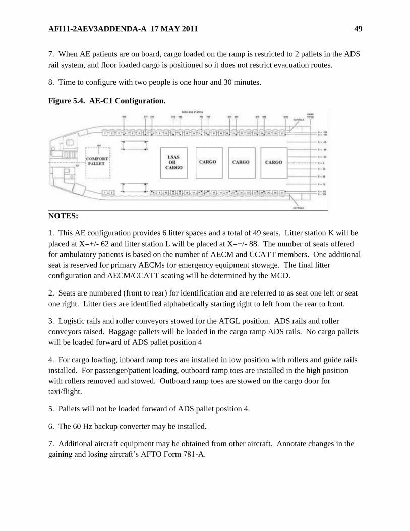
AFI11-2AEV3ADDENDA-A 17 MAY 2011 49
7. When AE patients are on board, cargo loaded on the ramp is restricted to 2 pallets in the ADS
rail system, and floor loaded cargo is positioned so it does not restrict evacuation routes.
8. Time to configure with two people is one hour and 30 minutes.
Figure 5.4. AE-C1 Configuration.
NOTES:
1. This AE configuration provides 6 litter spaces and a total of 49 seats. Litter station K will be
placed at X=+/- 62 and litter station L will be placed at X=+/- 88. The number of seats offered
for ambulatory patients is based on the number of AECM and CCATT members. One additional
seat is reserved for primary AECMs for emergency equipment stowage. The final litter
configuration and AECM/CCATT seating will be determined by the MCD.
2. Seats are numbered (front to rear) for identification and are referred to as seat one left or seat
one right. Litter tiers are identified alphabetically starting right to left from the rear to front.
3. Logistic rails and roller conveyors stowed for the ATGL position. ADS rails and roller
conveyors raised. Baggage pallets will be loaded in the cargo ramp ADS rails. No cargo pallets
will be loaded forward of ADS pallet position 4
4. For cargo loading, inboard ramp toes are installed in low position with rollers and guide rails
installed. For passenger/patient loading, outboard ramp toes are installed in the high position
with rollers removed and stowed. Outboard ramp toes are stowed on the cargo door for
taxi/flight.
5. Pallets will not be loaded forward of ADS pallet position 4.
6. The 60 Hz backup converter may be installed.
7. Additional aircraft equipment may be obtained from other aircraft. Annotate changes in the
gaining and losing aircraft’s AFTO Form 781-A.

50 AFI11-2AEV3ADDENDA-A 17 MAY 2011
8. When AE patients are on board, cargo loaded on the ramp is restricted to 2 pallets in the ADS
rail system, and floor loaded cargo is positioned so it does not restrict evacuation routes.
9. Time to configure with two people is 40 minutes.
AFI11-2AEV3ADDENDA-A 17 MAY 2011 51
Chapter 6
KC-135 CONFIGURATIONS
6.1. Mission Execution.
6.1.1. Limit total number of souls on board to 40. NOTE: At no time will SOB exceed the
number of available seat belts and life support equipment.
6.1.2. Additional Mission Requirements will include: NOTE: If unable to meet this
requirement, notify TACC.
6.1.2.1. Patient Support Pallet (PSP) with components based on configuration
requirements.
6.1.2.2. Appropriate number aft facing stud mounted seats. (Installed at tanker home
station). Coordination is required when MP-2 airline seats are located at the staging point.
6.1.2.3. Functional Latrine and a minimum of two urine tubes.
6.1.2.4. Two latrine cartridges (from tanker home station).
6.1.2.5. Ensure there are a minimum of 25 passenger information cards (KC-135
Passenger Emergency Procedures), AFVA11-226, 01 Oct 2001 (from tanker home
station). Cards can be ordered from the Air Force (AF) Publishing site.
6.2. Aircraft Systems.
6.2.1. Oxygen.
6.2.1.1. Therapeutic oxygen. Not available on the KC-135. Utilize the PTLOX, or
compressed oxygen tanks as available.
6.2.1.2. Patient emergency oxygen. Utilize EPOS.
6.2.1.3. Crew Oxygen. Supplied via 12 gaseous oxygen bottles (6 primary/6 secondary)
for demand regulators and recharger hoses.
6.2.2. Electrical. The PSP does not have electrical provisions. Electrical power for 400 Hz
medical equipment is provided by an approved KC-135, 400 Hz pigtail adaptor (P/N
8564034-135) located in the Electrical Cord Assembly Set (ECAS). Electrical power for 60
Hz medical equipment is provided by the portable Avionics or Unitron Frequency Converter
using the Frequency Converter Adapter Adaptive Electrical Pigtail (P/N 8564034-140).
6.2.2.1. The release of TCTO 1C-135-1806 provides three additional electrical outlets on
the KC-135 R/T block 40 aircraft. Locations of the outlets are at station 445, 645, and
745. Each outlet provides a 115 VAC 3-phase 400hz 45 amp. The three new outlets and
the galley plug provide a total of 180 amps. For AE missions, utilization of the Avionics
or Unitron Frequency Converter and/or KC-135 ECAS adapter(s) are authorized. Any or
all of the outlets may be utilized on AE missions, however, do not exceed the 30 amp
capability of the frequency converter at individual outlets. The CMT will calculate total
equipment amperage prior to connecting equipment to the aircraft or Avionics/Unitron
Frequency Converter.

52 AFI11-2AEV3ADDENDA-A 17 MAY 2011
6.2.2.2. Coordinate with BO for galley disconnect and pulling of circuit breakers before
connecting the pigtail adaptor to the aircraft (Table 6.10). When connecting the pigtail
adaptor to the galley plugs, ensure both circuit breakers marked ―GALLEY PWR‖ and
―Station 445‖ are pulled. Home station maintenance group will lock out/tag all
incompatible power receptacles and document on AFTO IMT 781A, Maintenance
Discrepancy and work document.
6.2.2.3. Use the following guidance when connecting/disconnecting the KC-135, 400 Hz
pigtail adaptor (P/N 8564034-135) or KC-135 Avionics/Unitron Frequency Converter,
Adaptive Electrical Pigtail (P/N 8564034-140):
6.2.2.3.1. KC-135 R and T models have different labels for the circuit breakers to be
pulled when connecting/disconnecting the AE pigtails. AECMs will request the BO to
open/reset the appropriate circuit breakers when connecting/disconnecting the AE
pigtail adaptor.
6.2.2.3.1.1. The R and T models identify the three circuit breakers for the Galley
Plug, as GALLEY POWER located on the Main Circuit Breaker Panel. BO will
pull all three circuit breakers.
6.2.2.3.2. Insert KC-135 pigtail adaptor (P/N 8564034-135) from AE ECAS into
aircraft receptacle. If using the Avionics/Unitron Frequency Converter, connect the
Adaptive Electrical Pigtail (P/N 8564034-140) securely to the Avionics Frequency
Converters 25 ft Input Power Cable prior to securing to aircraft power receptacle.
6.2.2.3.3. BO will reset circuit breakers.
6.2.2.3.4. If using KC-135 pigtail adaptor (P/N 8564034-135), accomplish AC
testing IAW AFI 10-2909, AE Equipment Standards. Once AC testing is
accomplished, secure all ECAS connections with plastic tie-straps. Secure the portion
of the ECAS cord closest to the pigtail to a non-moving aircraft part. NOTES: The
Avionics/Unitron Frequency Converter does not require AC testing at or aft of the
duplex outlets. Follow plastic tie-strap procedure in 6.6.2.3.4. for medical equipment
plugs at the terminal end of the ECAS, AC electrical extension cord. Tie-straps
should be 15 inches in length to adequately cover all circumferences.
6.2.2.3.4.1. When using the Avionics/Unitron Frequency Converter, aircraft
circuit breaker will not be pulled when adding or removing medical equipment.
The frequency converter has built in circuit breakers associated with each duplex
outlet that provides adequate protection when adding or removing medical
equipment. When adding or removing medical equipment, turn off the
corresponding duplex outlet. WARNING: The Airdyne 3500 Air Compressor is
not approved for use on the KC-135.
6.2.3. Temperature. The greatest challenge to ground operations during summer is potential
high cabin temperatures. The KC-135 interior heats up very quickly and can place significant
thermal stress on patients and crew.
6.2.3.1. The KC-135 air conditioning system is not operated on the ground. AE crews
will request ground air conditioning units when ambient air temperature is 84 degrees or
greater.

AFI11-2AEV3ADDENDA-A 17 MAY 2011 53
6.2.3.2. The PIC/MCD will request an air conditioning cart whenever patients/crew is on
board and the ambient temperature may exceed a comfortable level.
6.2.3.3. In extreme heat conditions, utilize air conditioning carts to cold soak the aircraft.
Locate one each at the over wing hatch and one at the aft emergency escape hatch.
6.2.3.4. Other alternatives are: schedule morning or evening departure/arrivals; open
over wing exits to promote air circulation (hatches must be installed prior to engine start);
and in extreme situations MCD may request the PIC to declare AIREVAC priority.
NOTE: Follow guidance in 6.2.3.1. Use alternatives methods as interim or last resort.
6.2.3.4.1. The PIC may request ―AIREVAC priority‖ for preferential ATC handling
due to inadequate temperature control during preflight and taxi. AIREVAC priority
will only be used for that portion of the flight requiring expedited handling. It is the
PIC’s responsibility to use this option for bonafide medical situations that demand
priority handling.
6.2.3.5. In-flight the aircraft’s temperature can be regulated by the BO. Optimal patient
locations are mid-cabin, mid-tier for a litter patient.
6.2.3.6. The floor is very cold and the ceiling area is very warm. Ensure the bottom litter
patients have blankets available.
6.2.4. Lighting. KC-135 lighting consists of ceiling mounted incandescent lights and one
positional light, located on (R) hand side, forward cabin (map light).
6.2.4.1. Some KC-135 models have a second positional light, located on the (L) hand
side, forward cabin.
6.2.4.2. Positional lights are helpful to illuminate specific patients in the litter stanchion
area.
6.2.4.3. AECMs will bring supplemental lighting on board, as required.
6.2.4.4. The entire crew and all patients and personnel aboard will exercise extreme
caution when moving in the main cabin.
6.3. Miscellaneous Information.
6.3.1. The Patient Movement Requirements Center (PMRC) should coordinate with the
medical facility nutritional support centers to prepare specialty meals. Schedule meals to
arrive to aircraft 1 ½ hours prior to departure.
6.3.1.1. The appropriate mission support agency (detachment, squadron etc) should make
arrangements with Fleets Service to obtain coolers for meal storage. Box lunches may be
broken down, storing only sandwiches and cold drinks in the coolers, to maximize cooler
storage space.
6.3.2. Hygiene. Latrine capacity is limited. This should be taken into consideration for
planning procedures. The aircraft will depart home station with an operable latrine, a
minimum of two urine tubes and two latrine cartridges.
6.3.2.1. The CMT will verify the latrine knife blade handle is in the open/out position
and that the latrine is fully functional when uploading the PSP. Patients and attendants
should be encouraged to use available restroom facilities prior to enplaning the aircraft.
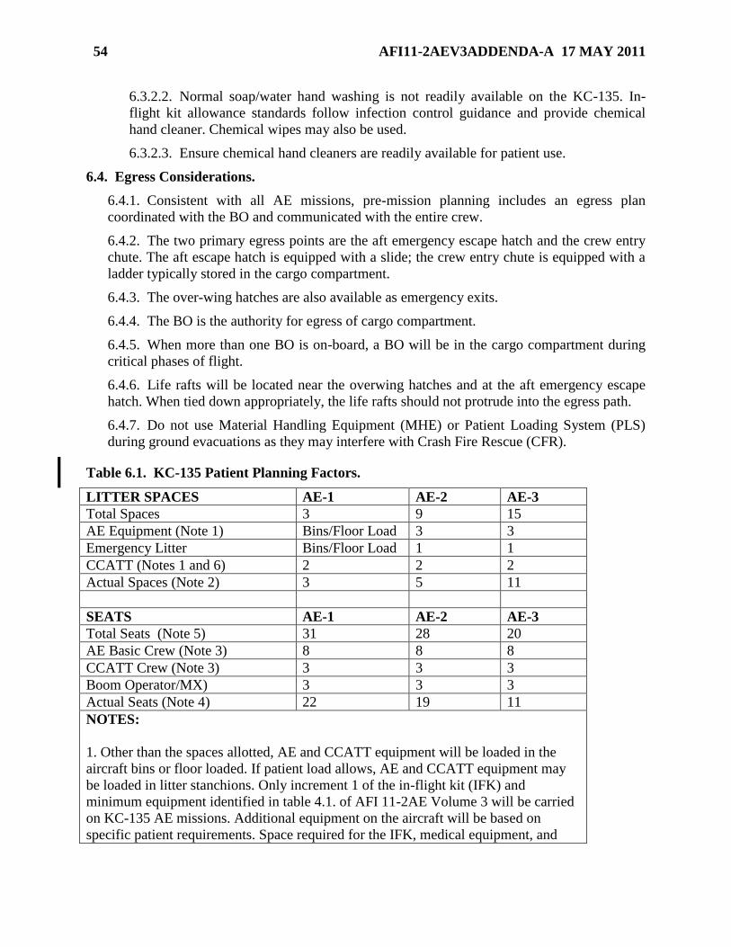
54 AFI11-2AEV3ADDENDA-A 17 MAY 2011
6.3.2.2. Normal soap/water hand washing is not readily available on the KC-135. In-
flight kit allowance standards follow infection control guidance and provide chemical
hand cleaner. Chemical wipes may also be used.
6.3.2.3. Ensure chemical hand cleaners are readily available for patient use.
6.4. Egress Considerations.
6.4.1. Consistent with all AE missions, pre-mission planning includes an egress plan
coordinated with the BO and communicated with the entire crew.
6.4.2. The two primary egress points are the aft emergency escape hatch and the crew entry
chute. The aft escape hatch is equipped with a slide; the crew entry chute is equipped with a
ladder typically stored in the cargo compartment.
6.4.3. The over-wing hatches are also available as emergency exits.
6.4.4. The BO is the authority for egress of cargo compartment.
6.4.5. When more than one BO is on-board, a BO will be in the cargo compartment during
critical phases of flight.
6.4.6. Life rafts will be located near the overwing hatches and at the aft emergency escape
hatch. When tied down appropriately, the life rafts should not protrude into the egress path.
6.4.7. Do not use Material Handling Equipment (MHE) or Patient Loading System (PLS)
during ground evacuations as they may interfere with Crash Fire Rescue (CFR).
Table 6.1. KC-135 Patient Planning Factors.
LITTER SPACES AE-1 AE-2 AE-3
Total Spaces 3 9 15
AE Equipment (Note 1) Bins/Floor Load 3 3
Emergency Litter Bins/Floor Load 1 1
CCATT (Notes 1 and 6) 2 2 2
Actual Spaces (Note 2) 3 5 11
SEATS AE-1 AE-2 AE-3
Total Seats (Note 5) 31 28 20
AE Basic Crew (Note 3) 8 8 8
CCATT Crew (Note 3) 3 3 3
Boom Operator/MX) 3 3 3
Actual Seats (Note 4) 22 19 11
NOTES:
1. Other than the spaces allotted, AE and CCATT equipment will be loaded in the
aircraft bins or floor loaded. If patient load allows, AE and CCATT equipment may
be loaded in litter stanchions. Only increment 1 of the in-flight kit (IFK) and
minimum equipment identified in table 4.1. of AFI 11-2AE Volume 3 will be carried
on KC-135 AE missions. Additional equipment on the aircraft will be based on
specific patient requirements. Space required for the IFK, medical equipment, and
AFI11-2AEV3ADDENDA-A 17 MAY 2011 55
emergency get down litter will not exceed 4 litter spaces.
2. Actual litter spaces may decrease based upon patient requirements and equipment.
An emergency litter will be carried on all AE missions.
3. AE and CCATT seats are based on primary crew complement. The MCD/CMT
and the 2FN/2AET will share one seat for equipment stowage. The 3AET will have
one seat to store equipment. In the event that space allows, each AECM will be given
one seat for equipment stowage.
4. Actual seats may decrease based on crew complement, mission requirements and
patient load.
5. For an AE-3 configuration, a total of 3 seats may be placed on PSP M. Additional
sidewall seating can be configured on the left side between pallet position 720 and
840 for 2 AECMs.
6. For CCATT vented and non-vented patients refer to figures 6.4. through 6.9.
7. AECMs will provide BO with final Gross Weight (GW) of each pallet prior to
engine start. GW will include PSP pallet, PSP equipment, AE equipment and
patients..
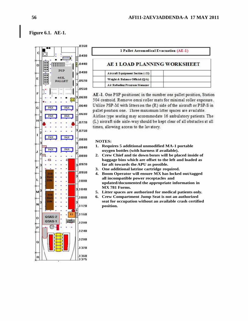
56 AFI11-2AEV3ADDENDA-A 17 MAY 2011
Figure 6.1. AE-1.
NOTES:
1. Requires 5 additional unmodified MA-1 portable
oxygen bottles (with harness if available).
2. Crew Chief and tie down boxes will be placed inside of
baggage bins which are offset to the left and loaded as
far aft towards the APU as possible.
3. One additional latrine cartridge required.
4. Boom Operator will ensure MX has locked out/tagged
all incompatible power receptacles and
updated/documented the appropriate information in
MX 781 Forms.
5. Litter spaces are authorized for medical patients only.
6. Crew Compartment Jump Seat is not an authorized
seat for occupation without an available crash certified
position.
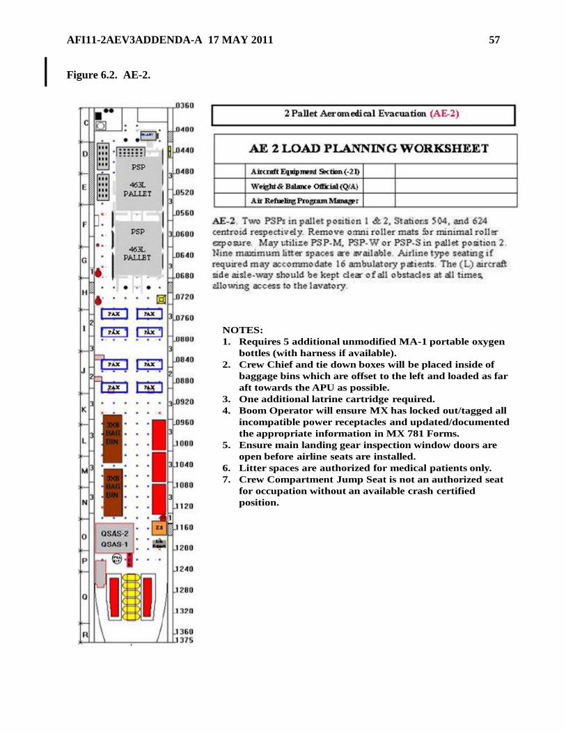
AFI11-2AEV3ADDENDA-A 17 MAY 2011 57
Figure 6.2. AE-2.
NOTES:
1. Requires 5 additional unmodified MA-1 portable oxygen
bottles (with harness if available).
2. Crew Chief and tie down boxes will be placed inside of
baggage bins which are offset to the left and loaded as far
aft towards the APU as possible.
3. One additional latrine cartridge required.
4. Boom Operator will ensure MX has locked out/tagged all
incompatible power receptacles and updated/documented
the appropriate information in MX 781 Forms.
5. Ensure main landing gear inspection window doors are
open before airline seats are installed.
6. Litter spaces are authorized for medical patients only.
7. Crew Compartment Jump Seat is not an authorized seat
for occupation without an available crash certified
position.
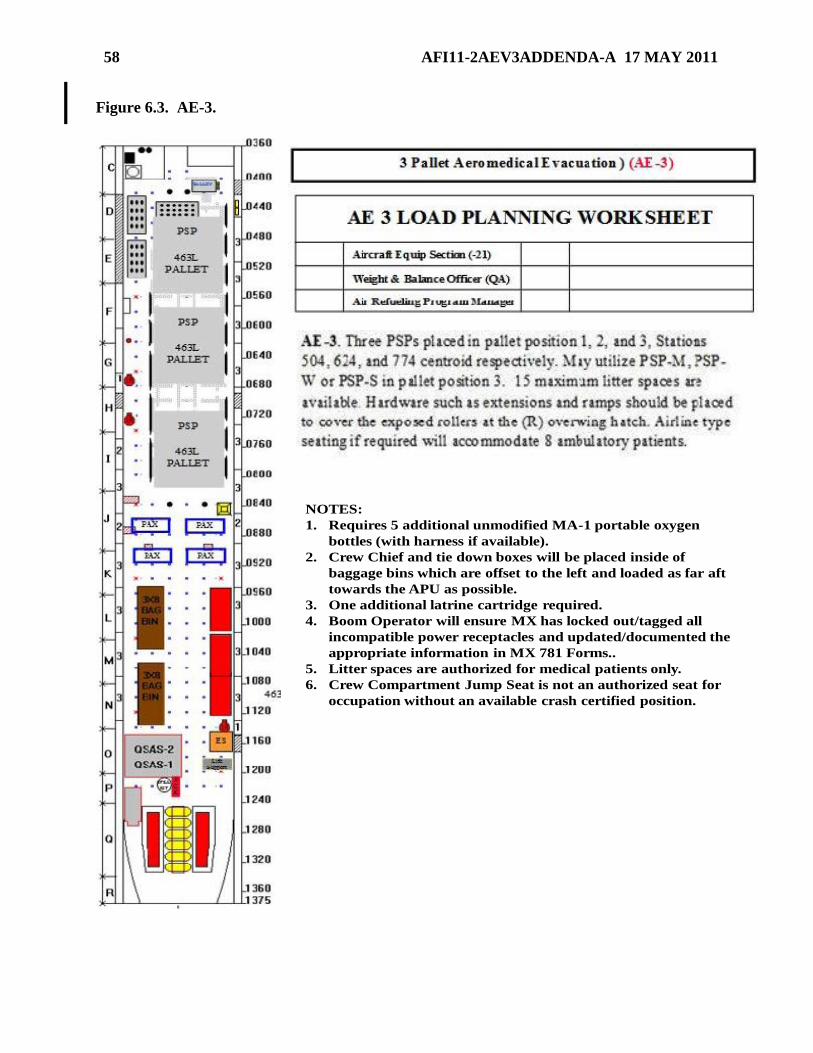
58 AFI11-2AEV3ADDENDA-A 17 MAY 2011
Figure 6.3. AE-3.
NOTES:
1. Requires 5 additional unmodified MA-1 portable oxygen
bottles (with harness if available).
2. Crew Chief and tie down boxes will be placed inside of
baggage bins which are offset to the left and loaded as far aft
towards the APU as possible.
3. One additional latrine cartridge required.
4. Boom Operator will ensure MX has locked out/tagged all
incompatible power receptacles and updated/documented the
appropriate information in MX 781 Forms..
5. Litter spaces are authorized for medical patients only.
6. Crew Compartment Jump Seat is not an authorized seat for
occupation without an available crash certified position.
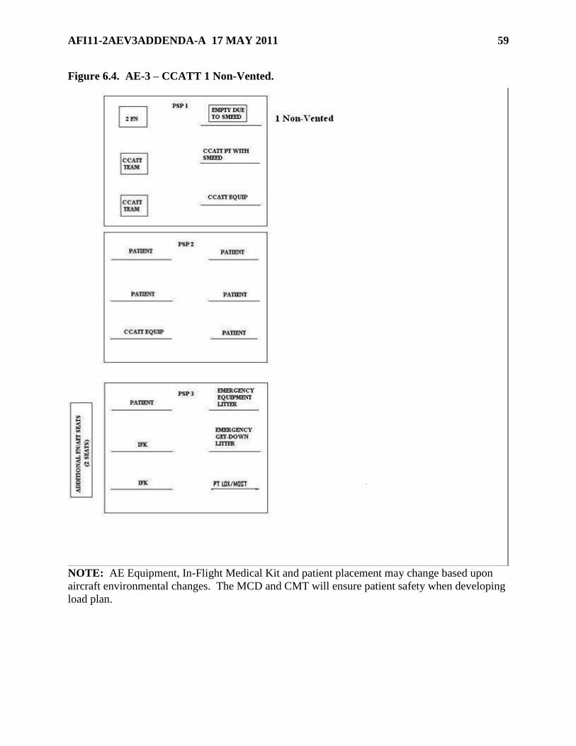
AFI11-2AEV3ADDENDA-A 17 MAY 2011 59
Figure 6.4. AE-3 – CCATT 1 Non-Vented.
NOTE: AE Equipment, In-Flight Medical Kit and patient placement may change based upon
aircraft environmental changes. The MCD and CMT will ensure patient safety when developing
load plan.

60 AFI11-2AEV3ADDENDA-A 17 MAY 2011
Figure 6.5. AE-3 – CCATT 2 Non-Vented.
NOTE: AE Equipment, In-Flight Medical Kit and patient placement may change based upon
aircraft environmental changes. The MCD and CMT will ensure patient safety when developing
load plan.
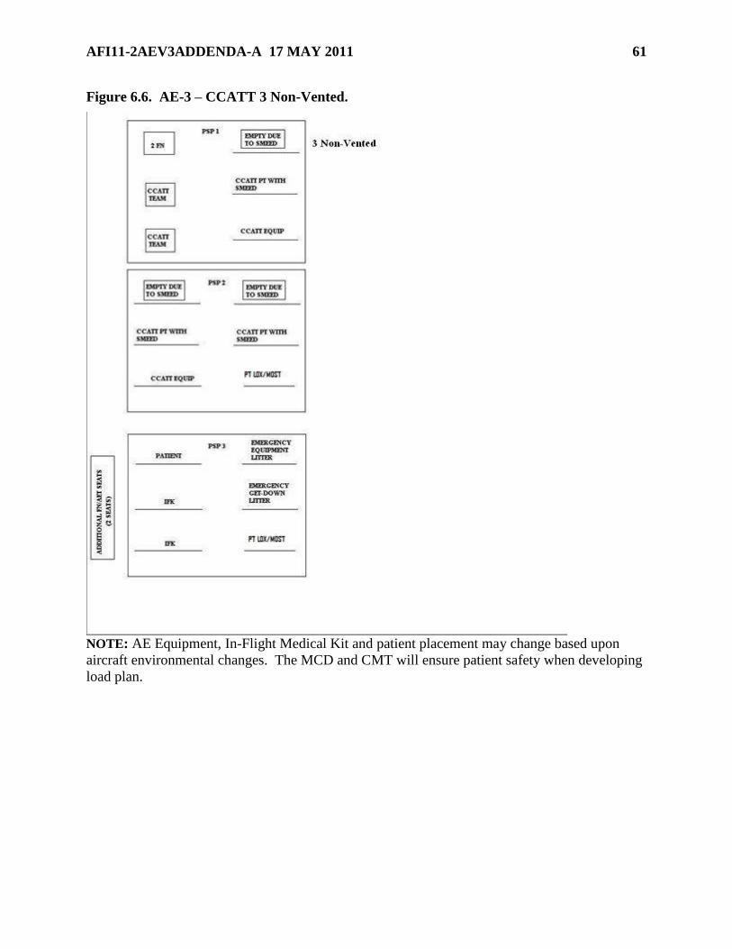
AFI11-2AEV3ADDENDA-A 17 MAY 2011 61
Figure 6.6. AE-3 – CCATT 3 Non-Vented.
NOTE: AE Equipment, In-Flight Medical Kit and patient placement may change based upon
aircraft environmental changes. The MCD and CMT will ensure patient safety when developing
load plan.

62 AFI11-2AEV3ADDENDA-A 17 MAY 2011
Figure 6.7. AE-3 – CCATT 1 Vented.
NOTE: AE Equipment, In-Flight Medical Kit and patient placement may change based upon
aircraft environmental changes. The MCD and CMT will ensure patient safety when developing
load plan.

AFI11-2AEV3ADDENDA-A 17 MAY 2011 63
Figure 6.8. AE-3 – CCATT 2 Vented.
NOTE: AE Equipment, In-Flight Medical Kit and patient placement may change based upon
aircraft environmental changes. The MCD and CMT will ensure patient safety when developing
load plan.
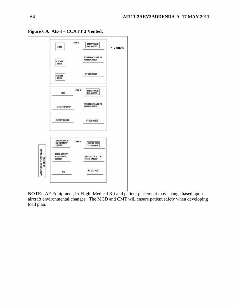
64 AFI11-2AEV3ADDENDA-A 17 MAY 2011
Figure 6.9. AE-3 – CCATT 3 Vented.
NOTE: AE Equipment, In-Flight Medical Kit and patient placement may change based upon
aircraft environmental changes. The MCD and CMT will ensure patient safety when developing
load plan.

AFI11-2AEV3ADDENDA-A 17 MAY 2011 65
Figure 6.10. KC-135 Circuit Breaker Panel.
NOTE: Pull the corresponding circuit breakers for the highlighted stations.
66 AFI11-2AEV3ADDENDA-A 17 MAY 2011
Chapter 7
C-21 CONFIGURATION
7.1. SPECTRUM 500-LP (MILITARY VERSION) MODEL 2500US.
7.1.1. General. The SPECTRUM 500 LP is the current unit approved for use on C-21
aeromedical evacuation missions. The litter system has self-contained oxygen, vacuum,
compressed air, electrical power and an overhead light. This unit plugs directly into aircraft
power.
7.1.2. The aircraft manufacturer will install the SPECTRUM on the right side of the aircraft
with the closet removed.
7.1.3. Specifications.
7.1.3.1. Bench Length: 75" (190.5cm) [including end mounts]
7.1.3.2. Width: 17" (43.25cm)
7.1.3.3. Height: 10.5" (26.67cm) to top of bench
7.1.3.4. Standard Unit Weight: 150 lbs. (68.04kgs)
7.1.3.5. Air Pump Capacity: 11.89 Lpm @ 42 psi [4.0Amps 4.3 lbs (1.95kgs)]
7.1.3.6. Vacuum Pump: 10.47 Lpm @ 15 in. hg. [2.5Amps 4.3lbs (1.95kgs)]
7.1.3.7. Power Required: 28VDC Aircraft electrical power (45.5 Total Amps.)
7.1.3.8. Electrical Supply: (2) 115 volt AC duplex receptacles provide 3 amps per duplex
(6 amps total).
7.1.3.8.1. (1) 28 volt DC receptacle provides 7.5 amps
7.1.3.9. Dual 350 watt, 115 volt 15.6 Amp AC Inverters 4.8lbs. (2.177kgs)
7.1.3.10. Oxygen Supply: 3,500 L, M Cylinder.
7.1.3.11. Dual Pneumatics
7.1.3.12. Mobile Overhead Pneumatics
7.1.3.13. Supply Outlets: Oxygen, Air, Vacuum
7.1.3.14. IV mounts (4)
7.1.3.15. IV Pole
7.1.4. Components.
7.1.4.1. Stretcher. Removable and designed to carry a patient in either the prone or
supine position. The bottom edge has four Teflon lined rings, which slide along the
patient loading ramp. A closed pneumatic cylinder allows the patient’s backrest to be
lifted up and down. The stretcher locks into the ends of the modular base. The stretcher
has two armrests.
AFI11-2AEV3ADDENDA-A 17 MAY 2011 67
7.1.4.2. Overhead Pneumatic Console. Mounts on the back of the modular base with two
quick connect pins. It can slide forward and aft along the base. The hoses to the oxygen,
air, and vacuum outlets connect on the forward end of the modular base using the
pneumatic quick connect couplings.
7.1.4.3. Patient Loader. A high polished aluminum folding ramp used to slide the
stretcher between a gurney on the ground and the modular base. The patient loader
connects to the base using an equipment mount located at the end of the base. Two short
legs at the connecting end of the patient loader swing down to support the unit. The ramp
is then unfolded on the ground outside the aircraft using a pair of telescoping legs. The
legs are extended from a spring loaded, foot-operated release. When the release is
activated, the outboard end of the ramp may be adjusted up and down to allow for easier
stretcher movement into the aircraft. CAUTION: The Patient Loader maximum weight
capacity is 350 lbs.
7.1.4.4. Equipment Table. Connects to the modular base using both equipment mounts
on either end of the base. The table is designed to allow auxiliary medical equipment to
be belted to the table and secured for flight.
7.1.4.5. IV Pole. Fits in any of the four equipment mounts and is for securing IV fluids
or approved pole mounted medical equipment. It telescopes up and down and may also
be mounted directly to the side of the stretcher at the shoulder position.
7.1.4.6. Seat Rail Adapter. Fits on the seat rails of the aircraft. The SPECTRUM base is
mounted to this adapter. The adapter is secured to the rail with a series of drop in pins.
NOTE: Upon AE crew arrival to the aircraft, ensure the SPECTRUM oxygen and
suction equipment is available.
7.1.5. Spectrum Preflight.
7.1.5.1. If aircraft power is not on, direct PIC to turn aircraft power on.
7.1.5.2. Turn on oxygen supply valve, located on the lower aft end of the unit, to full
counter-clockwise position. Check oxygen pressure gauge to ensure it reads at least 1700
psi.
7.1.5.3. Turn on panel and overhead light switches to check for proper operation.
7.1.5.4. Turn on vacuum pump switch. Ensure both vacuum gauges read at least 14 Hg.
7.1.5.5. Turn on air compressor switch. Ensure both air gauges read at least 46-52 psi.
7.1.5.6. Turn on electrical inverter switch ―A.‖ Wait 15 seconds to ensure inverter turns
on. Connect test load (if available) of AC power, not to exceed 3 amps. Disconnect the
test load and shut off the inverter. Perform same check on electrical inverter ―B.‖
7.1.5.7. Ensure all circuit breakers are in operating position.
7.1.5.8. Check for proper operation of stretcher locks.
7.1.5.9. Turn off all switches and ensure the oxygen supply valve is closed until needed.
NOTE: Notify the PIC and maintenance if preflight problems are encountered. To ensure
the safety of the patient and to prevent damage to the aircraft, do not allow ground
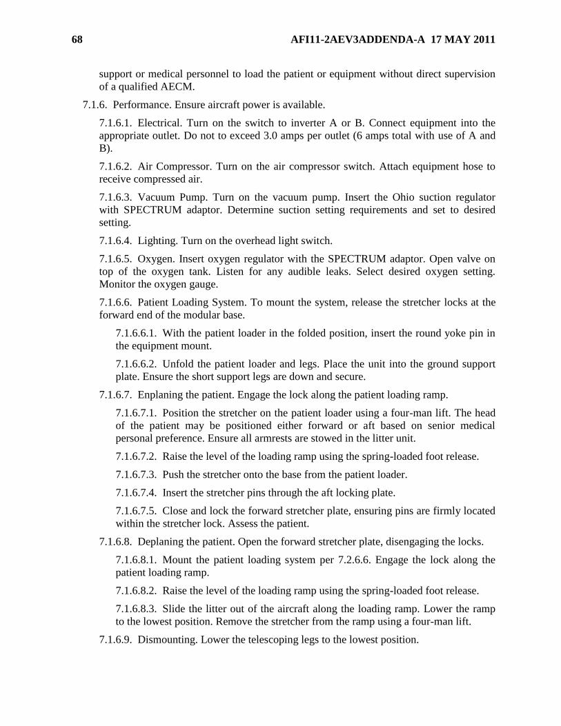
68 AFI11-2AEV3ADDENDA-A 17 MAY 2011
support or medical personnel to load the patient or equipment without direct supervision
of a qualified AECM.
7.1.6. Performance. Ensure aircraft power is available.
7.1.6.1. Electrical. Turn on the switch to inverter A or B. Connect equipment into the
appropriate outlet. Do not to exceed 3.0 amps per outlet (6 amps total with use of A and
B).
7.1.6.2. Air Compressor. Turn on the air compressor switch. Attach equipment hose to
receive compressed air.
7.1.6.3. Vacuum Pump. Turn on the vacuum pump. Insert the Ohio suction regulator
with SPECTRUM adaptor. Determine suction setting requirements and set to desired
setting.
7.1.6.4. Lighting. Turn on the overhead light switch.
7.1.6.5. Oxygen. Insert oxygen regulator with the SPECTRUM adaptor. Open valve on
top of the oxygen tank. Listen for any audible leaks. Select desired oxygen setting.
Monitor the oxygen gauge.
7.1.6.6. Patient Loading System. To mount the system, release the stretcher locks at the
forward end of the modular base.
7.1.6.6.1. With the patient loader in the folded position, insert the round yoke pin in
the equipment mount.
7.1.6.6.2. Unfold the patient loader and legs. Place the unit into the ground support
plate. Ensure the short support legs are down and secure.
7.1.6.7. Enplaning the patient. Engage the lock along the patient loading ramp.
7.1.6.7.1. Position the stretcher on the patient loader using a four-man lift. The head
of the patient may be positioned either forward or aft based on senior medical
personal preference. Ensure all armrests are stowed in the litter unit.
7.1.6.7.2. Raise the level of the loading ramp using the spring-loaded foot release.
7.1.6.7.3. Push the stretcher onto the base from the patient loader.
7.1.6.7.4. Insert the stretcher pins through the aft locking plate.
7.1.6.7.5. Close and lock the forward stretcher plate, ensuring pins are firmly located
within the stretcher lock. Assess the patient.
7.1.6.8. Deplaning the patient. Open the forward stretcher plate, disengaging the locks.
7.1.6.8.1. Mount the patient loading system per 7.2.6.6. Engage the lock along the
patient loading ramp.
7.1.6.8.2. Raise the level of the loading ramp using the spring-loaded foot release.
7.1.6.8.3. Slide the litter out of the aircraft along the loading ramp. Lower the ramp
to the lowest position. Remove the stretcher from the ramp using a four-man lift.
7.1.6.9. Dismounting. Lower the telescoping legs to the lowest position.
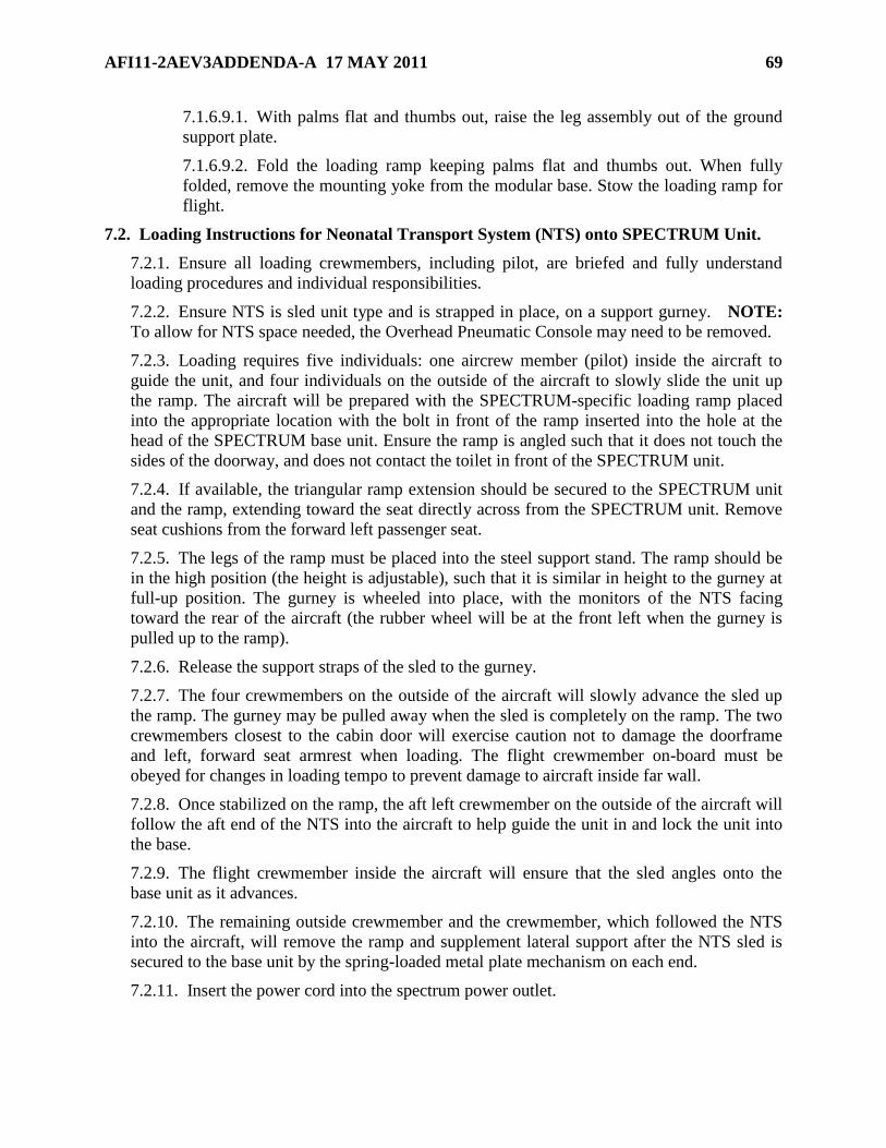
AFI11-2AEV3ADDENDA-A 17 MAY 2011 69
7.1.6.9.1. With palms flat and thumbs out, raise the leg assembly out of the ground
support plate.
7.1.6.9.2. Fold the loading ramp keeping palms flat and thumbs out. When fully
folded, remove the mounting yoke from the modular base. Stow the loading ramp for
flight.
7.2. Loading Instructions for Neonatal Transport System (NTS) onto SPECTRUM Unit.
7.2.1. Ensure all loading crewmembers, including pilot, are briefed and fully understand
loading procedures and individual responsibilities.
7.2.2. Ensure NTS is sled unit type and is strapped in place, on a support gurney. NOTE:
To allow for NTS space needed, the Overhead Pneumatic Console may need to be removed.
7.2.3. Loading requires five individuals: one aircrew member (pilot) inside the aircraft to
guide the unit, and four individuals on the outside of the aircraft to slowly slide the unit up
the ramp. The aircraft will be prepared with the SPECTRUM-specific loading ramp placed
into the appropriate location with the bolt in front of the ramp inserted into the hole at the
head of the SPECTRUM base unit. Ensure the ramp is angled such that it does not touch the
sides of the doorway, and does not contact the toilet in front of the SPECTRUM unit.
7.2.4. If available, the triangular ramp extension should be secured to the SPECTRUM unit
and the ramp, extending toward the seat directly across from the SPECTRUM unit. Remove
seat cushions from the forward left passenger seat.
7.2.5. The legs of the ramp must be placed into the steel support stand. The ramp should be
in the high position (the height is adjustable), such that it is similar in height to the gurney at
full-up position. The gurney is wheeled into place, with the monitors of the NTS facing
toward the rear of the aircraft (the rubber wheel will be at the front left when the gurney is
pulled up to the ramp).
7.2.6. Release the support straps of the sled to the gurney.
7.2.7. The four crewmembers on the outside of the aircraft will slowly advance the sled up
the ramp. The gurney may be pulled away when the sled is completely on the ramp. The two
crewmembers closest to the cabin door will exercise caution not to damage the doorframe
and left, forward seat armrest when loading. The flight crewmember on-board must be
obeyed for changes in loading tempo to prevent damage to aircraft inside far wall.
7.2.8. Once stabilized on the ramp, the aft left crewmember on the outside of the aircraft will
follow the aft end of the NTS into the aircraft to help guide the unit in and lock the unit into
the base.
7.2.9. The flight crewmember inside the aircraft will ensure that the sled angles onto the
base unit as it advances.
7.2.10. The remaining outside crewmember and the crewmember, which followed the NTS
into the aircraft, will remove the ramp and supplement lateral support after the NTS sled is
secured to the base unit by the spring-loaded metal plate mechanism on each end.
7.2.11. Insert the power cord into the spectrum power outlet.
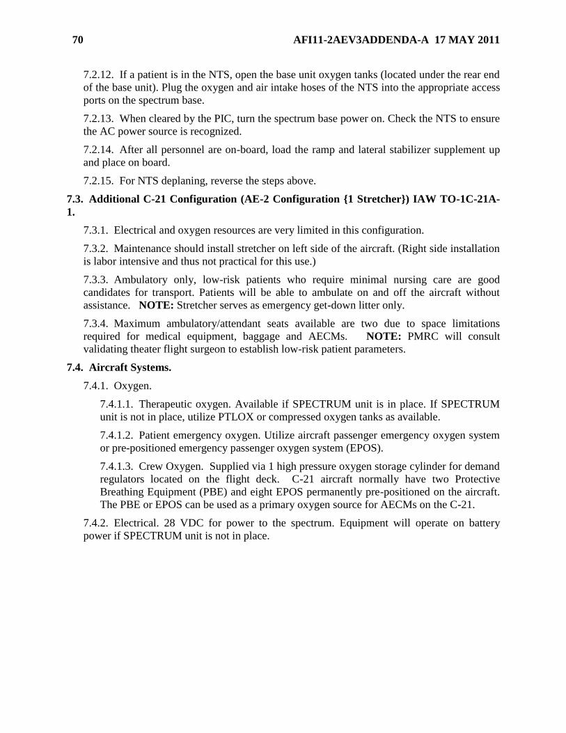
70 AFI11-2AEV3ADDENDA-A 17 MAY 2011
7.2.12. If a patient is in the NTS, open the base unit oxygen tanks (located under the rear end
of the base unit). Plug the oxygen and air intake hoses of the NTS into the appropriate access
ports on the spectrum base.
7.2.13. When cleared by the PIC, turn the spectrum base power on. Check the NTS to ensure
the AC power source is recognized.
7.2.14. After all personnel are on-board, load the ramp and lateral stabilizer supplement up
and place on board.
7.2.15. For NTS deplaning, reverse the steps above.
7.3. Additional C-21 Configuration (AE-2 Configuration {1 Stretcher}) IAW TO-1C-21A-
1.
7.3.1. Electrical and oxygen resources are very limited in this configuration.
7.3.2. Maintenance should install stretcher on left side of the aircraft. (Right side installation
is labor intensive and thus not practical for this use.)
7.3.3. Ambulatory only, low-risk patients who require minimal nursing care are good
candidates for transport. Patients will be able to ambulate on and off the aircraft without
assistance. NOTE: Stretcher serves as emergency get-down litter only.
7.3.4. Maximum ambulatory/attendant seats available are two due to space limitations
required for medical equipment, baggage and AECMs. NOTE: PMRC will consult
validating theater flight surgeon to establish low-risk patient parameters.
7.4. Aircraft Systems.
7.4.1. Oxygen.
7.4.1.1. Therapeutic oxygen. Available if SPECTRUM unit is in place. If SPECTRUM
unit is not in place, utilize PTLOX or compressed oxygen tanks as available.
7.4.1.2. Patient emergency oxygen. Utilize aircraft passenger emergency oxygen system
or pre-positioned emergency passenger oxygen system (EPOS).
7.4.1.3. Crew Oxygen. Supplied via 1 high pressure oxygen storage cylinder for demand
regulators located on the flight deck. C-21 aircraft normally have two Protective
Breathing Equipment (PBE) and eight EPOS permanently pre-positioned on the aircraft.
The PBE or EPOS can be used as a primary oxygen source for AECMs on the C-21.
7.4.2. Electrical. 28 VDC for power to the spectrum. Equipment will operate on battery
power if SPECTRUM unit is not in place.
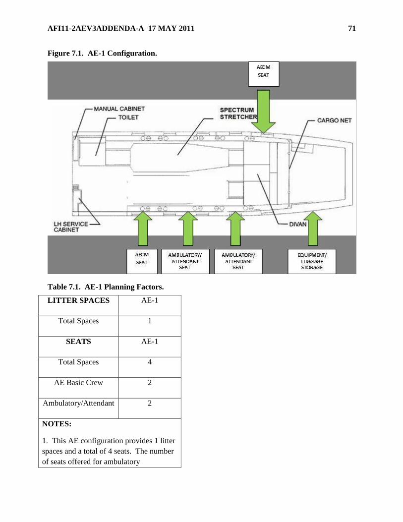
AFI11-2AEV3ADDENDA-A 17 MAY 2011 71
Figure 7.1. AE-1 Configuration.
Table 7.1. AE-1 Planning Factors.
LITTER SPACES AE-1
Total Spaces 1
SEATS AE-1
Total Spaces 4
AE Basic Crew 2
Ambulatory/Attendant 2
NOTES:
1. This AE configuration provides 1 litter
spaces and a total of 4 seats. The number
of seats offered for ambulatory

72 AFI11-2AEV3ADDENDA-A 17 MAY 2011
patients/attendants are based on the basic
C-21 AE Aircrew Complement.
2. For C-21 transports with a Neonatal or
Critical Care Air Transport Team
(CCATT), the AE crew may be limited to
one (1) AECM due to weight and space
limitations.
3. AE/CCATT/NICU
equipment/supplies, crew baggage and
patient baggage should be stored in the aft
compartment.
Figure 7.2. AE-2 Configuration.
Table 7.2. AE-2 Planning Factors.
LITTER SPACES AE-2
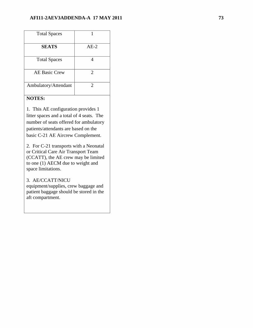
AFI11-2AEV3ADDENDA-A 17 MAY 2011 73
Total Spaces 1
SEATS AE-2
Total Spaces 4
AE Basic Crew 2
Ambulatory/Attendant 2
NOTES:
1. This AE configuration provides 1
litter spaces and a total of 4 seats. The
number of seats offered for ambulatory
patients/attendants are based on the
basic C-21 AE Aircrew Complement.
2. For C-21 transports with a Neonatal
or Critical Care Air Transport Team
(CCATT), the AE crew may be limited
to one (1) AECM due to weight and
space limitations.
3. AE/CCATT/NICU
equipment/supplies, crew baggage and
patient baggage should be stored in the
aft compartment.

74 AFI11-2AEV3ADDENDA-A 17 MAY 2011
Chapter 8
FLOOR LOADING
8.1. C-130 Floor Loading.
8.1.1. Floor-loading procedures for loading patients are authorized for all contingency
operations when a time critical environment exists (i.e. non-secure landing zones, areas faced
with enemy siege/hostile fire, humanitarian reasons, etc.), and minimum ground time is
essential. Floor-loading procedures can be practiced and trained during Aeromedical
Readiness Missions (ARM), joint training operations, exercises, etc. The cargo area floor will
be configured with all rollers stowed.
8.1.2. Ambulatory Patients: If available, any cushioning material may be used for seating, to
prevent the patient from having to sit on the bare cargo area floor. Seat ambulatory patients
so they face forward in the aircraft. Attach a cargo tie-down strap for each row of patients, in
a manner that it will provide forward restraint and body stability. See T.O. 1C-130X-9A for
proper use of the tie-down device.
8.1.3. Litter Patients: Two crewmembers are required to work simultaneously in securing the
opposite sides of the litters to the floor (applies when securing two or three litters together).
Position litters side-by-side and longitudinally on the cargo area floor, with the patient’s head
toward the aft of the aircraft. A total of 15 litter patients can be floor-loaded on the C-130.
This is comprised of 5 rows of three litters. Medical equipment can be secured on a litter(s)
in the ―I‖ or ―L‖ sidewall litter tier or on the ramp. Secure the litters to the aircraft floor using
the following procedures. (See Figures 8.1 – 8.3) NOTE: Maximum altitude for floor-
loaded patients is flight level 350 (FL350). NOTE: An additional two pallet positions are
available on the C-130J-30 model that can accommodate an additional 6 litter patients.
8.1.3.1. One litter: Use one tie-down device at each end of the litter. Center litter over
tie down ring column ―D‖. Connect hook end of device to tie down ring column ―C‖,
and run strap webbing over the litter handles, wrapping once around each handle. Attach
the ratchet end of the tie-down device to tie down ring column ―E‖. Remove slack from
strap webbing, and ratchet the device. Repeat process at other end of litter. Ensure
ratchets have a minimum of 1½ turns of webbing around the spindle.
Figure 8.1. C-130 One Litter.

AFI11-2AEV3ADDENDA-A 17 MAY 2011 75
8.1.3.2. Two litters: Use one tie-down device at each end of the litter. Align inboard litter
handles over tie down ring column ―D‖. Connect hook end of device to tie down ring
column C or E, and run strap over outside handle, wrap once around center handles, strap
over outside handle. Attach the ratchet end of the tie-down device to tie down ring
column C or E. Remove slack from strap webbing, and ratchet the device. Repeat process
at other end of litter. Ensure ratchets have a minimum of 1½ turns of webbing around the
spindle.
Figure 8.2. C-130 Two Litters.
8.1.3.3. Three Litters: Three Litters: Use one tie-down device at each end of the litter.
Position outside litters as close to tie down ring column B and F as possible to create a
center aisle. Connect hook end of device to tie down ring column B or F. Pass over first
handle, wrap center handles, pass strap over last handle and then hook ratchet into tie
down ring column D. Ensure ratchets have a minimum of 1½ turns of webbing around
the spindle.
Figure 8.3. C-130 Three Litters.
8.2. C-17 Floor Loading.
8.2.1. Floor-loading procedures for loading patients are authorized for all contingency
operations when a time critical environment exists (i.e. non-secure landing zones, areas faced
with enemy siege/hostile fire, humanitarian reasons, etc.), and minimum ground time is
essential. Floor-loading procedures can be practiced/trained during ARMs, joint training
operations, exercises, etc. The cargo area floor will be configured with all rollers stowed.

76 AFI11-2AEV3ADDENDA-A 17 MAY 2011
8.2.2. Ambulatory Patients: If available, any cushioning material may be used for seating, to
prevent the patient from having to sit on the bare cargo area floor. Seat ambulatory patients
so they face forward in the aircraft. Attach a cargo tie-down strap for each row of patients, in
a manner that it will provide forward restraint and body stability. See T.O. 1C-17-9A for
proper use of the tie-down device.
8.2.3. Litter Patients: Two crewmembers are required to work simultaneously in securing the
opposite sides of the litters to the floor (applies when securing two or three litters together).
Position litters side-by-side and longitudinally on the cargo area floor, with the patient’s head
toward the aft of the aircraft. A total of 48 litter patients can be floor-loaded on the C-17.
This is comprised of 8 rows of two groups of three litter patients. The first row of litters starts
at FS 360. Additional 12 litter patients can be placed on the ramp for maximum utilization of
the aircraft. Maximum altitude for floor-loaded patients is flight level 350 (FL350).
8.2.3.1. One litter: Use one tie-down device at each end of the litter. Center litter over
―D‖ column. Connect clamp end of device to row ―C‖, and run strap webbing over the
litter handles, wrapping once around each handle. Attach the hook on the ratchet end of
the tie-down device to the tie-down ring on row ―E‖. Remove slack from strap webbing,
and ratchet the tightening device. Repeat process at other end of litter. Ensure ratchets
have 1½ turns.
Figure 8.4. C-17 One Litter.
8.2.3.2. Two litters: Use one tie-down device at each end of the litter. Align inboard litter
handles over ―D‖ column. Connect clamp end of device to row C or E, and run strap over
outside handle, wrap once around center handles, strap over outside handle. Attach the
hook on the ratchet end of the tie-down device to the tie-down ring on row C or E.
Remove slack from strap webbing, and ratchet the tightening device. Repeat process at
other end of litter. Ensure ratchets have 1½ turns.
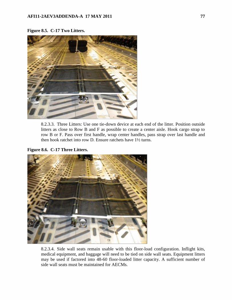
AFI11-2AEV3ADDENDA-A 17 MAY 2011 77
Figure 8.5. C-17 Two Litters.
8.2.3.3. Three Litters: Use one tie-down device at each end of the litter. Position outside
litters as close to Row B and F as possible to create a center aisle. Hook cargo strap to
row B or F. Pass over first handle, wrap center handles, pass strap over last handle and
then hook ratchet into row D. Ensure ratchets have 1½ turns.
Figure 8.6. C-17 Three Litters.
8.2.3.4. Side wall seats remain usable with this floor-load configuration. Inflight kits,
medical equipment, and baggage will need to be tied on side wall seats. Equipment litters
may be used if factored into 48-60 floor-loaded litter capacity. A sufficient number of
side wall seats must be maintained for AECMs.
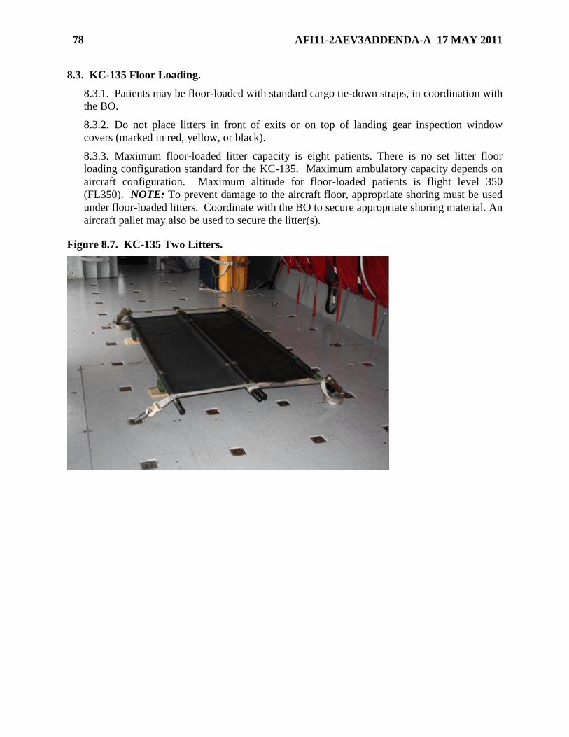
78 AFI11-2AEV3ADDENDA-A 17 MAY 2011
8.3. KC-135 Floor Loading.
8.3.1. Patients may be floor-loaded with standard cargo tie-down straps, in coordination with
the BO.
8.3.2. Do not place litters in front of exits or on top of landing gear inspection window
covers (marked in red, yellow, or black).
8.3.3. Maximum floor-loaded litter capacity is eight patients. There is no set litter floor
loading configuration standard for the KC-135. Maximum ambulatory capacity depends on
aircraft configuration. Maximum altitude for floor-loaded patients is flight level 350
(FL350). NOTE: To prevent damage to the aircraft floor, appropriate shoring must be used
under floor-loaded litters. Coordinate with the BO to secure appropriate shoring material. An
aircraft pallet may also be used to secure the litter(s).
Figure 8.7. KC-135 Two Litters.

AFI11-2AEV3ADDENDA-A 17 MAY 2011 79
Chapter 9
OPPORTUNE AIRCRAFT SYSTEMS
9.1. KC-10 Systems.
9.1.1. Oxygen.
9.1.1.1. Therapeutic oxygen. Not available on the KC-10. Utilize PTLOX or compressed
oxygen tanks as available.
9.1.1.2. AECM emergency oxygen. AE crew will utilize the four portable oxygen
cylinders located in the crew bunks. An additional portable oxygen cylinder will be
procured from the Air Refueling Operators (ARO) station. Coordinate with the PIC/BO.
Attach mask to bottle, but do not perform PRICE check. NOTE: Bunk occupants will
use EPOS in place of the portable oxygen cylinders. Patient emergency oxygen.
Ambulatory patients and patients on PSPs will utilize the aircraft drop down/seat or wall
mounted emergency oxygen system. Dixie cup masks provide 22 minutes of oxygen
regardless of cabin altitude. Floor-loaded patients will use EPOS.
9.1.2. Electrical.
9.1.2.1. Electrical power for medical equipment is provided by Avionics or Unitron
Frequency Converter and Adaptive KC-10 Electrical Pigtail (P/N 8564034-145).
9.1.2.2. Coordinate with the BO prior to electrical outlet use and prior to electrical
frequency converter placement.
9.1.2.3. There are four electrical outlets available in the cargo compartment which may
be used for AE and they provide a source of 115-200V/400 Hz. These outlets are
installed along the right-hand cargo compartment wall, approximately 10 inches above
the floor, aft of the cabin doors (including the deactivated over wing door).
9.1.2.4. The four 115 V/400 Hz outlets provide a total of 20 amps.
9.2. C-5 Systems.
9.2.1. Oxygen.
9.2.1.1. Therapeutic oxygen. Not available on the C-5. Utilize the PTLOX or
compressed oxygen tanks as available. Coordinate with LM prior to therapeutic oxygen
placement.
9.2.1.1.1. Patient transport in courier compartment. Secure PTLOX in the cargo
compartment and run oxygen lines through the hand hold in the floor escape hatch. If
using compressed oxygen tanks (H-tanks), secure tanks in the closet across from the
courier seat.
9.2.1.1.2. Patient transport in troop compartment. Secure PTLOX in the cargo
compartment and run oxygen lines up the side of the troop stairwell. If using
compressed oxygen tanks, secure tanks to the stairwell guard.
9.2.1.1.3. The PTLOX require up to 300 feet of additional oxygen connecting hose
(DISS receptacle to DISS plug) from the cargo compartment to the patient.
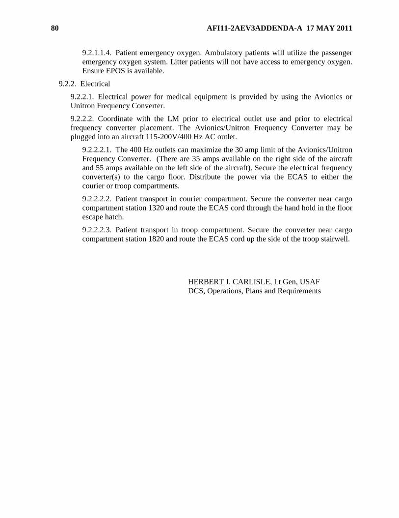
80 AFI11-2AEV3ADDENDA-A 17 MAY 2011
9.2.1.1.4. Patient emergency oxygen. Ambulatory patients will utilize the passenger
emergency oxygen system. Litter patients will not have access to emergency oxygen.
Ensure EPOS is available.
9.2.2. Electrical
9.2.2.1. Electrical power for medical equipment is provided by using the Avionics or
Unitron Frequency Converter.
9.2.2.2. Coordinate with the LM prior to electrical outlet use and prior to electrical
frequency converter placement. The Avionics/Unitron Frequency Converter may be
plugged into an aircraft 115-200V/400 Hz AC outlet.
9.2.2.2.1. The 400 Hz outlets can maximize the 30 amp limit of the Avionics/Unitron
Frequency Converter. (There are 35 amps available on the right side of the aircraft
and 55 amps available on the left side of the aircraft). Secure the electrical frequency
converter(s) to the cargo floor. Distribute the power via the ECAS to either the
courier or troop compartments.
9.2.2.2.2. Patient transport in courier compartment. Secure the converter near cargo
compartment station 1320 and route the ECAS cord through the hand hold in the floor
escape hatch.
9.2.2.2.3. Patient transport in troop compartment. Secure the converter near cargo
compartment station 1820 and route the ECAS cord up the side of the troop stairwell.
HERBERT J. CARLISLE, Lt Gen, USAF
DCS, Operations, Plans and Requirements

AFI11-2AEV3ADDENDA-A 17 MAY 2011 81
Attachment 1
GLOSSARY OF REFERENCES AND SUPPORTING INFORMATION
References
AFI 10-201, Status of Resources and Training System, 13 Apr 2006
AFI 10-2909, Aeromedical Evacuation Equipment Standards, 19 May 2008
AFI 10-402, Vol 1, Mobilization Planning and Personnel Readiness, 9 Aug 2007
AFI 10-403, Deployment Planning and Execution, 13 Jan 2008
AFI 10-601, Operational Capability Requirements Development, 12 Jul 2010
AFI 11-202, Vol 3, General Flight Rules, 22 Oct 2010
AFI 11-215, USAF Flight Manuals Program (FMP), 22 Dec 2008
AFPD 11-2, Aircraft Rules and Procedures, 14 Jan 2005
AFPD 11-3, Life Support , 9 Apr 1993
AFI 11-301, Vol 1, Aircrew Flight Equipment (AFE) Program, 25 Feb 2009
AFI 11-301, Vol 2, Maintenance and Configuration Requirements for Mobility Air Forces
(MAF) Aircrew and Aircraft-Installed Aircrew Life Support Equipment (ALSE), 1 May 2006
AFI 11-401, Aviation Management, 10 Dec 2010
AFI 11-403, Aerospace Physiological Training Program, 20 Feb 2001
AFPD 16-8, Arming of Aircrew, Mobility, and Oversea Personnel, 18 May 1993
AFI 21-101, Aircraft and Equipment Maintenance Management, 26 Jul 2010
AFI 21-103, Equipment Inventory, Status, and Utilization Reporting, 9 Apr 2010
AFI 21-112, Aircrew Egress Systems Maintenance, 7 Sep 2001
AFI 32-2001, Fire Emergency Services Program, 9 Sep 2008
AFI 36-2201, Air Force Training Program, 15 Sep 2010
AFOSH STD 48-137, Respiratory Protection Program, 10 Feb 2005
Adopted Forms
AFTO IMT 244, Industrial/Support Equipment Record
AFTO IMT 781A, Maintenance Discrepancy and Work Document
AF Form 847, Recommendation for Change of Publication
AF Form 1297, Temporary Issue Receipt
DD Form 365-4, Weight and Balance Clearance Form F - Transport/Tactical
DD Form 1148, Requisition and Invoice/Shipping Document
82 AFI11-2AEV3ADDENDA-A 17 MAY 2011
Abbreviations and Acronyms
ACM—additional crewmember
ADS—aerial delivery system
AE—aeromedical evacuation
AEC—aeromedical evacuation crews
AECM—aeromedical evacuation crewmember
AECT—aeromedical evacuation control team
AET—aeromedical evacuation technician
ASK—auxiliary survival kit
AFE—aircrew flight equipment
AFI—Air Force instruction
AFRC—Air Force Reserve Command
AMC—Air Mobility Command
AMCC—air mobility control center
AMD—air mobility division
AMOCC—air mobility operation control center
AMOG—air mobility operations group
ANG—Air National Guard
AOR—area of responsibility
APCC—aerial port control center
APS—aerial port squadron
ARC—Air Reserve Component
ARM—aeromedical readiness mission
ARMS—aviation resource management system
BO—boom operator
C2—command and control
CC—commander
CCATT—critical care aeromedical transport team
CFR—crash/fire/rescue
CG—center of gravity
CMT—charge medical technician
CONOPS—concept of operations

AFI11-2AEV3ADDENDA-A 17 MAY 2011 83
CONUS—continental United States
CRAF—civil reserve air fleet
DIRMOPFOR—director, mobility forces
DO—director of operations
DOD—Department of Defense
ECAS—electrical cable assembly set
PBE—Protective Breathing Equipment
EPOS—emergency passenger oxygen system
ERO—engines running onload or offload
ETIC—estimated time in commission
FMP—flight manuals program
GDSS—global decision support system
HUMRO—humanitarian relief operation
IAW—in accordance with
ICAO—international civil aviation organization
ISS—in system select
LM—loadmaster
LPU—life preserver unit
LSAS—litter station augmentation set
MAF—mobility Air Forces
MAJCOM—major command
MCD—medical crew director
MDS—mission design series
MHE—material handling equipment
NAF—numbered Air Force
NGB—National Guard Bureau
NTS—neonatal transport system
OPORD—operations order
OPR—office of primary responsibility
PACAF—Pacific Air Forces
PBE—protective breathing equipment
PCK—protective clothing kit

84 AFI11-2AEV3ADDENDA-A 17 MAY 2011
PDO—publications distribution office
PIC—pilot in command
PLS—patient loading system
PSP—patient support pallet
PTLOX—portable therapeutic liquid oxygen
RDS—records disposition schedule
SPIN—special instructions
TACC—tanker airlift control center (AMC)
TCN—transportation control number
TMO—traffic management
TO—technical order
TSO—technical standard order
USAFE—United States Air Forces in Europe
WFHQ—warfighting headquarters
Terms
Aeromedical Evacuation (AE)—The movement of patients under medical supervision to and
between medical treatment facilities by air transportation. (Joint Pub 1-02)
Aeromedical Evacuation Crew Members (AECM)—Qualified flight nurses (FN), aeromedical
evacuation technicians (AET), and unqualified student trainees under the direct supervision of a
qualified instructor or FN, performing AE duties.
Aircrew Flight Equipment (AFE)— AFE encompasses all equipment that is part of the 412A
life support system, to include items maintained by the previous career fields of Aircrew Life
Support (ALS) and Survival Equipment (SE), now the combined career field of AFE, as outlined
in the AFI 11-301 series.
Area of Operations (AO)—An operational area defined by the joint force commander for land
and naval forces. Areas of operation do not typically encompass the entire operational area of the
joint force commander, but should be large enough for component commanders to accomplish
their missions and protect their forces. Also called AO. See also area of responsibility; joint
operations area; joint special operations area.
Bare Base—A base having minimum essential facilities to house, sustain, and support
operations to include, if required, a stabilized runway, taxiways, and aircraft parking areas. A
bare base must have a source of water that can be made potable. Other requirements to operate
under bare base conditions form a necessary part of the force package deployed to the bare base.
Passenger (PAX)—Individual aboard aircraft for the purpose of transportation.
Pilot Unit—Unit designated by the MAJCOM FM to handle LOGDET management
responsibilities for an UTC. Pilot units are listed in the header record of each UTC and
LOGDET.

AFI11-2AEV3ADDENDA-A 17 MAY 2011 85
Primary Crewmember—Any person, rated or nonrated, and required on aircraft to accomplish
flying mission.
Theater (DOD)—The geographical area outside the continental United States for which a
commander of a combatant command has been assigned responsibility.
Unit Manpower Document (UMD)—A detailed staffing list reflecting the distribution of
staffing allocations into a finite structure of authorizations (by work center).
Unit Type Code (UTC)—A five-character, alphanumeric code that uniquely identifies each type
unit of the Armed Forces.