by order of the commander air force...
TRANSCRIPT

BY ORDER OF THE COMMANDER
AIR FORCE MATERIEL COMMAND
AIR FORCE MATERIEL COMMAND
MANUAL 23-101 VOLUME 3
17 NOVEMBER 2016
Certified Current 12 January 2017Materiel Management
COMPUTATIONAL
RESULTS (D200A, D200N)
COMPLIANCE WITH THIS PUBLICATION IS MANDATORY
ACCESSIBILITY: Publications and forms/IMTs are available for downloading or ordering on
the e-publishing website at www.e-Publishing.af.mil
RELEASABILITY: There are no releasability restrictions on this publication
OPR: AFMC/A4RM Certified by: AFMC/A4R
(Col Deirdre A. Mahon)
Pages: 94
This publication implements Air Force Instruction (AFI) 23-101, Air Force Materiel
Management. It prescribes guidance and procedural instructions for computing XD2, XB3, and
XF3 secondary item requirements. It applies Secondary Item Requirements System
(SIRS)(D200A) and Central Secondary Item Stratification (CSID)(D200N) users. This
publication does not apply to Air Force Reserve units and the Air National Guard (ANG). Refer
recommended changes and questions about this publication to the Office of Primary
Responsibility (OPR) using an AF Form 847, Recommendation for Change of Publication; route
AF Forms 847 form the field through the appropriate functional’s chain of command. This
publication may be supplemented at any level, but must be routed to the OPR for coordination
prior to certification and approval. The authorities to waive wing/unit level requirements in this
publication are identified with a Tier (“T-0, T-1, T-2, T-3”) number following the compliance
statement. Submit requests for waivers using AF Form 679, Air Force Publication Compliance
Item Waiver Request/Approval, through the chain of command to the appropriate Tier waiver
approval authority, or alternately, to the Publication OPR for non-tiered compliance items.
Requests for waivers must be approved by the publication OPR prior to implementation. Ensure
that all records created as a result of processes prescribed in this publication are maintained In
Accordance With (IAW) Air Force Manual (AFMAN) 33-363, Management of Records, and
disposed of IAW Air Force Records Information Management System (AFRIMS) Records
Disposition Schedule (RDS). The use of the name or mark of any specific manufacturer,
commercial product, commodity, or service in this publication does not imply endorsement by
the Air Force.
2 AFMCMAN23-101V3 17 NOVEMBER 2016
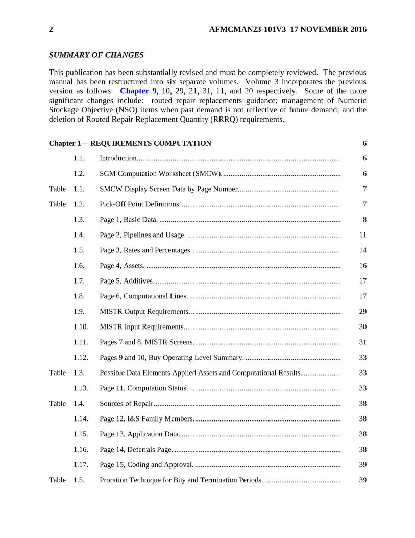
SUMMARY OF CHANGES
This publication has been substantially revised and must be completely reviewed. The previous
manual has been restructured into six separate volumes. Volume 3 incorporates the previous
version as follows: Chapter 9, 10, 29, 21, 31, 11, and 20 respectively. Some of the more
significant changes include: routed repair replacements guidance; management of Numeric
Stockage Objective (NSO) items when past demand is not reflective of future demand; and the
deletion of Routed Repair Replacement Quantity (RRRQ) requirements.
Chapter 1— REQUIREMENTS COMPUTATION 6
1.1. Introduction. ............................................................................................................ 6
1.2. SGM Computation Worksheet (SMCW). ............................................................... 6
Table 1.1. SMCW Display Screen Data by Page Number. ...................................................... 7
Table 1.2. Pick-Off Point Definitions. ..................................................................................... 7
1.3. Page 1, Basic Data. ................................................................................................. 8
1.4. Page 2, Pipelines and Usage. .................................................................................. 11
1.5. Page 3, Rates and Percentages. ............................................................................... 14
1.6. Page 4, Assets. ........................................................................................................ 16
1.7. Page 5, Additives. ................................................................................................... 17
1.8. Page 6, Computational Lines. ................................................................................. 17
1.9. MISTR Output Requirements. ................................................................................ 29
1.10. MISTR Input Requirements. ................................................................................... 30
1.11. Pages 7 and 8, MISTR Screens. .............................................................................. 31
1.12. Pages 9 and 10, Buy Operating Level Summary. ................................................... 33
Table 1.3. Possible Data Elements Applied Assets and Computational Results. .................... 33
1.13. Page 11, Computation Status. ................................................................................. 33
Table 1.4. Sources of Repair. ................................................................................................... 38
1.14. Page 12, I&S Family Members. .............................................................................. 38
1.15. Page 13, Application Data. ..................................................................................... 38
1.16. Page 14, Deferrals Page. ......................................................................................... 38
1.17. Page 15, Coding and Approval. .............................................................................. 39
Table 1.5. Proration Technique for Buy and Termination Periods. ......................................... 39

AFMCMAN23-101V3 17 NOVEMBER 2016 3
Chapter 2— ITEM RECOMPUTATIONS 40
2.1. Introduction. ............................................................................................................ 40
2.2. “For Real” Item Recomputation. ............................................................................ 40
2.3. “What If” Item Recomputation. .............................................................................. 41
2.4. Simulation Additives. ............................................................................................. 42
Table 2.1. SADR Screen - Additive Requirements That Can Be Simulated. .......................... 42
2.5. Simulation Adjusted Levels. ................................................................................... 43
2.6. Simulation Basic Management Data (SBMD). ....................................................... 43
Table 2.2. SBMD Screen Data Elements That Can Be Changed. ............................................ 43
2.7. Simulation Factors. ................................................................................................. 43
2.8. Simulation I-S Additive Requirements. .................................................................. 44
2.9. Simulation Item Programs. ..................................................................................... 44
2.10. Simulation Non Time-Phased Assets. ..................................................................... 44
Table 2.3. SNTP Screen Data Elements by Asset Category That Can Be Changed. ............... 45
2.11. Simulation Pipeline Data Screen. ........................................................................... 45
2.12. Simulation MISTR Repair and Repair Data. .......................................................... 45
2.13. Simulation Time-Phased Assets. ............................................................................ 45
2.14. Simulation Usage. ................................................................................................... 46
Table 2.4. SUSD Screen Data Elements That Can Be Changed. ............................................. 46
2.15. Simulation War Data. ............................................................................................. 46
Chapter 3— SAFETY LEVELS PRODUCTS 47
3.1. Introduction. ............................................................................................................ 47
3.2. Aircraft Availability Model Products. .................................................................... 47
Chapter 4— OTHER WAR RESERVE MATERIEL 51
4.1. Introduction. ............................................................................................................ 51
4.2. Inputs to the OWRM Computation. ........................................................................ 51
4.3. OWRM Computation Logic. .................................................................................. 52
4.4. File Maintenance of War Data Elements. ............................................................... 53
4.5. War Total OIM Demand Rate................................................................................. 54

4 AFMCMAN23-101V3 17 NOVEMBER 2016
4.6. War Rates and Factors (Table 4. ............................................................................. 54
Table 4.1. War Rates and Factors Data. ................................................................................... 55
4.7. War Pipeline Days (Table 4. ................................................................................... 55
Table 4.2. War Pipeline Days. ................................................................................................. 56
4.8. Other War Data. ...................................................................................................... 57
4.9. The SGM OWRM Computation Worksheet. .......................................................... 58
Table 4.3. SGM OWRM Computation Worksheet Data. ........................................................ 59
Chapter 5— INSURANCE ITEMS AND NUMERIC STOCKAGE OBJECTIVE ITEMS 61
5.1. Introduction. ............................................................................................................ 61
5.2. INS Items. ............................................................................................................... 61
5.3. NSO Items............................................................................................................... 62
5.4. Levels for INS and NSO Items. .............................................................................. 63
5.5. Special Rules for Items Managed by Multiple Services. ........................................ 63
5.6. INS/NSO Item Status Listing.................................................................................. 64
5.7. Data Elements of Display INIS INS/NSO Item Status Listing Screen (Page 1). ... 64
Table 5.1. Data Elements of Display INIS INS/NSO Item Status Listing Screen (Page 1). ... 65
5.8. Data Elements of Display INS/NSO Item Status Listing (Repair Detail) and
(Buy/Retention Detail), (Pages 2 and 3, First Screen). ............................................ 66
Table 5.2. Data Elements of Display INS/NSO Item Status Listing (Repair Detail) and
(Buy/Retention Detail) (Pages 2 and 3, First Screen). ............................................. 67
5.9. Data Elements of INS/NSO Item Status Listing (Repair Detail) and
(Buy/Retention Detail) (Pages 2 and 3, Second Screen). ........................................ 69
Table 5.3. Data Elements of INS/NSO Item Status Listing (Repair Detail) and
(Buy/Retention Detail) (Pages 2 and 3, Second Screen). ........................................ 69
5.10. Display INIS INS/NSO Item Status Listing (I&S Family Members) (Page 4). ..... 69
5.11. INIS INS/NSO Item Status Listing Report. ............................................................ 69
Table 5.4. Summary Data Elements of INIS INS/NSO Item Status Listing Report. ............... 70
Chapter 6— INDEX OF ACTIONS PRODUCTS 71
6.1. Introduction. ............................................................................................................ 71
6.2. The Buy, Termination and Excess IOA Products. .................................................. 71

AFMCMAN23-101V3 17 NOVEMBER 2016 5
Table 6.1. Buy, Termination and Excess IOA Products. ......................................................... 71
6.3. The Repair IOA Products........................................................................................ 71
Table 6.2. Repair IOA Reports. ............................................................................................... 72
6.4. Format for the Net Buy, Termination, and Excess IOA Reports (Table 6. ............. 72
Table 6.3. Data Common to IOA Reports for Net Buy, Termination and Excess Reports. .... 73
Table 6.4. Data Specific to IOA Reports for Net Buy. ............................................................ 74
Table 6.5. Data Specific to IOA Reports for Net Terminations. .............................................. 74
Table 6.6. Data Specific to IOA Reports for Net Excess. ........................................................ 75
6.5. Format of the Repair IOAs Reports (Table 6. ......................................................... 75
Table 6.7. Data Specific to IOAs Reports for Repair. ............................................................. 75
6.6. Display IOAs Screens. ............................................................................................ 76
Attachment 1— GLOSSARY OF REFERENCES AND SUPPORTING INFORMATION 78

6 AFMCMAN23-101V3 17 NOVEMBER 2016
Chapter 1
REQUIREMENTS COMPUTATION
1.1. Introduction. This chapter describes the basic methodology used to compute
replenishment spares requirements utilizing the Secondary Item Requirement System
(SIRS)(D200A). This chapter also provides guidance on buys and excess. Repair and
termination guidance is addressed in AFMCMAN 23-101, Volume 4, IMS/PMS/MM Data and
Reports (D200A, D200N), Chapter 8 and AFMCMAN 23-101, Volume 1, General
D200A/D200N Information, Chapter 4 respectively. Types of items and time periods are
described in AMCMAN 23-1, Volume 1, Chapter 1. For each item, SIRS computes factors by
dividing the actual usage by the past programs. The factors times the future programs determine
the projected usage. Added to the projected usage are stock levels, repair cycles, projected
condemnations, Readiness Spares Package (RSP) requirements, and additive requirements to
determine the gross requirements. Then assets are subtracted in three increments from the gross
requirements to determine the net requirements for the item. Management products are prepared
during each requirements computation process for review by the Inventory Management
Specialist (IMS)/Materiel Manager (MM), the Equipment Specialist (ES), and higher levels of
management. The requirements appear on the following three (different) documents that can be
viewed online: Insurance (INS)/Numeric Stockage Objective (NSO) Item Status Listing (the
INIS screen, see Chapter 5), Subgroup Master (SGM) Computation Worksheet Requirements
(the SMCW screens), and SGM Other War Reserve Materiel (OWRM) Computation Worksheet
(the SOCW screens, see Chapter 4). These documents are usually printed after each SIRS
computation
1.2. SGM Computation Worksheet (SMCW).
1.2.1. The IMS/MM will use the SMCW Rqmts as the signature, review, and approval
document for computing items (see AFMCMAN 23-101, Volume 1, paragraph 1.4.2.5.).
The hard copy product is automatically generated after each SIRS computation for items
computing a buy, termination, repair, excess, or based on the Item Activity Code (IAC). For
items computing excess, this product is produced only if this is the first time the item is in
excess, or if the current computed excess quantity is larger than last cycle’s excess quantity.
1.2.2. This computation worksheet provides the computational results for computing items
by SGM stock number. The SGM computation is printed automatically for the Initial, Final,
and Summary computation runs. Printed products for the Final cycle are suppressed. The
printed copy displays all the same data as the online screens, plus 38 quarters (qtrs) of
computation data and Management of Items Subject To Repair (MISTR) lines, plus data at
the selected “pick-off” points, and information from the Notepads. On the display screens,
the SGM Computation provides only computation data and MISTR lines for selected “pick-
off” points. The SGM Computation can be viewed online with the command SIRS DIS CW
SMCW. The SMCW display screen has the 15 pages identified in Table 1.1

AFMCMAN23-101V3 17 NOVEMBER 2016 7
Table 1.1. SMCW Display Screen Data by Page Number.
SMCW
Page
Number
Data Presented
1 Basic Data
2 Pipelines and Usage
3 Rates and Percents
4 Assets
5 Additives
6 Computational Lines
7 Total MISTR Requirements
8 MISTR Input and Output Requirement broken out by Peacetime Operating Stock
(POS), War Readiness Spares Kits (WRSK) and Base Level Self-Sufficiency
Spares (BLSS) (now called RSP), and OWRM
9 Buy Operating Level Summary – Full
10 Buy Operating Level Summary – Limited
11 Summary and Levels
12 Interchangeability and Substitutability (I&S) Family Members
13 Application Data
14 Breakout of Buy Requirement
15 Coding of Actions and Approval Signatures (not used)
1.2.3. The pick-off points are defined in Table 1.2.
Table 1.2. Pick-Off Point Definitions.
Pick-Off Point Definition
1 1st qtr The immediate qtr following the asset cutoff date.
2 PCLT The future qtr that is Procurement Lead Time (PCLT) beyond the Asset
Cutoff Date.
3 CY Period (PD) The future qtr (period) that is PCLT beyond the end of the Current Year
(CY).
4 AY PD The future qtr that is PCLT beyond the end of the Apportionment Year
(AY).
5 BY PD The future qtr that is PCLT beyond the end of the Budget Year (BY).
6 EY PD The future qtr that is PCLT beyond the end of the Extended Year (EY).
7 Retention The Retention segment of the computation.
1.2.4. Each page displays the page number, site and division IMS code, product title
“SMCW Rqmts” and product control number, AD200.AI0108ZP. Also displayed on the
right is the Current Date (DD MMM YY), plus the time the report was printed, and the As of
Date (DD MMM YY) along with a 2-digit cycle indicator. The first position of the cycle
indicator will be either “I” for Initial computation, “F” for Final computation, or “S” for
Summary computation. The second position of the cycle indicator is numeric to indicate the
number of times that the computation has been re-run. Each page displays the SGM stock
number, the 2-digit site code that indicates where the NSN is managed (Oklahoma Air
Logistics Complex [OC], Ogden Air Logistics Complex [OO], San Antonio [SA], Warner-

8 AFMCMAN23-101V3 17 NOVEMBER 2016
Robins Air Logistics Complex [WR], Tx (contractor managed), or WP (Rolls-Royce jet
engines)], the IMS (3-digit code of the IMS/MM responsible for management of the item)
and the ES (3-digit code of the ES responsible for the applications and the rates and percents
used in the computation).
1.3. Page 1, Basic Data. The data elements on page 1 of the display screen are the same data
elements displayed on page 1 of the printed product.
1.3.1. Item Name. The name of the item comes from the Requirements Item Identification
Data (RIID) (D200E) system, and can be file maintained using the Basic Management Data
(BMD) screen (see AFMCMAN 23-101, Volume 4, paragraph 1.7.).
1.3.2. Prgm Sel. The 4-digit Item Program Select Code (IPSC) is file maintained by the ES
through the Applications, Programs, Indentures (API) D200F system. (See AFMCMAN 23-
101, Volume 5, Equipment Specialist Data and Reports (D200A, D200N), paragraph 3.26.)
1.3.3. Budget Code. This code is used to categorize items for purposes of funding,
budgeting, and safety level budget support objective assignment. It is made up of a 2-
position Budget Program (BP) code, plus a 4-position System Management Code (SMC),
plus a 4-position Materiel Program Code (MPC). The BP code identifies which funding area
will be assigned to the item. The MPC represents the type of materiel being acquired. It can
be file maintained in SIRS using the BMD screen (see AFMCMAN 23-101, Volume 4,
paragraph 1.2.).
1.3.4. Unit Prices. The actual/forecast prices and repair cost are displayed in dollars and
cents. The alpha position following the Unit Price and Repair Cost is the Source Reference
Code (SRC) that identifies the source of the price. “D” = the price originated from the
Master Item Identification Control System (MIICS), D043. “J” = the price came from the
Contracting Information Database System (J018R) via RIID. “C” = the forecast price or
repair cost has been calculated by SIRS. “E” = the price has been file maintained. (See
AFMCMAN 23-101, Volume 4, paragraph 1.11.)
1.3.4.1. Unit Price. The price from the latest procurement contract.
1.3.4.2. Fcst Unit Price. The Forecast Unit Price (FUP) of the item is determined by
multiplying the unit price times an inflation factor, based on the Date Of Last
Procurement (DOLP). See AFMCMAN 23-101, Volume 2, System Level Data and OPR
Reports (D200A, D200N), paragraph 3.16. for the inflation table.
1.3.4.3. Repair Cost. The repair cost is the average price that depot maintenance
(organic or contractor) charges to fix an item. See AFMCMAN 23-101, Volume 4,
paragraph 8.9. for how the weighted repair cost is calculated.
1.3.5. DOLP. The DOLP is in Julian date (YYDDD) format (see AFMCMAN 23-101,
Volume 4, paragraph 1.12.).
1.3.6. Recov I-S Ind. This is the recoverable I&S indicator to reflect the I&S structure of the
item. The indicator can be: “B” - bachelor item, “S” - SGM, or “M” - I&S family master.
The I&S structure of the item is displayed on page 12 of the online SMCW.
1.3.7. Mission Item Essentially Code (MIEC). The 3-position item MIEC for how essential
the item is to the wartime mission of the weapon system. It must be file maintained in API
(see AFMCMAN 23-101, Volume 5, paragraph 3.27.).

AFMCMAN23-101V3 17 NOVEMBER 2016 9
1.3.8. Act Cd. The single position Item Activity Code (IAC) indicates the quarterly cycle
that a review of the item is required and when products will be automatically printed. (See
AFMCMAN 23-101, Volume 4, paragraph 1.5.)
1.3.9. New Itm. SIRS will put an “N” in this code upon receipt of a new item, and will
change the code to blank 2 years after the oldest Program Begin Date (PBD) shown for the
item. SRC C is always displayed. This code cannot be file maintained. (See AFMCMAN
23-101, Volume 4, paragraph 1.14.9.)
1.3.10. Itm Cat. The Item Category Code (ICC) identifies the type of item being computed.
See AFMCMAN 23-101, Volume 4, paragraph 1.6. for how to file maintain this code. The
ICCs are as follows: Blank - Active, computing item (L, if weapon system life code is
greater than 0); I - INS item (Y, if weapon system life code greater than 0); and S - NSO item
(Z, if weapon system life code is greater than 0).
1.3.11. No. Users. The number of users displayed here is the number of Stock Record
Account Numbers (SRANs) that show a demand level greater than zero. The computation
uses the time-phased number of users displayed on page 6 (see paragraph 1.8.85).
1.3.12. PCLT, while not displayed, is the sum of Administrative Lead Time (ALT) plus
Production Lead Time (PLT). A total greater than 72 months may be shown, but a maximum
of 72 months is used in the computation. The buy point is calculated as the PCLT beyond
the end of the AY/operating year for all four cycles.
1.3.12.1. ALT Days. The ALT days come from RIID and can be file maintained. SIRS
accepts 1 to 999 days. (See AFMCMAN 23-101, Volume 4, paragraph 2.2.)
1.3.12.2. ALT Mo. The ALT days converted into months.
1.3.12.3. PLT Days. The PLT comes from RIID and can be file maintained. SIRS
accepts 1 to 2980 days. (See AFMCMAN 23-101, Volume 4, paragraph 2.3.)
1.3.12.4. PLT Mo. The PLT days converted into months.
1.3.13. ERRC. The ERRC items computed by SIRS are “N” (XB3), “P” (XF3), and “T”
(XD2). The ERRC comes from RIID and cannot be file maintained in SIRS. When the unit
price is less than unit repair cost, the item will be evaluated for change to “consumable”
verses a “reparable” based on procurement and repair history together with economic
considerations of “throw away” versus “repair it.” If an item breaches the 75% threshold, the
ES and engineer will review the item for possible ERRC code change. For further
information, see AFMAN 21-106, Joint Regulation Governing the Use and Application of
Uniform Source, Maintenance, and Recoverability Codes; AFH 23-123, Volume 1, Materiel
Management Reference Information, and Volume 2, Part 2, Integrated Logistics System-
Supply (ILS-S), Standard Base Supply System Operations,; AFMCMAN 23-3, Cataloging
and Standardization; AFMCI 23-112, Management of Items Subject to Repair (MISTR);
Technical Order (T.O.) 00-20-3, Maintenance Processing of Reparable Property and the
Repair Cycle Asset Control System; T.O. 00-25-195-WA-1, AF Technical Order System
Source, Maintenance, and Recoverability Coding of Air Force Weapons, Systems, and
Equipments; and AFMCMAN 23-101, Volume 4, paragraph 11.7.
1.3.14. U - I. The unit of issue comes from RIID. The code is for display only. It is not
used in the SIRS computation. The unit of issue cannot be file maintained in SIRS.

10 AFMCMAN23-101V3 17 NOVEMBER 2016
1.3.15. Interim Contractor Support (ICS)/Reliability Improvement Warranty (RIW). This
code indicates items that are being managed under ICS with a value of “C,” or the RIW
program with a value of “W.” The IMS/MM file maintains this code. (See AFMCMAN 23-
101, Volume 4, paragraph 1.4.1.)
1.3.16. Expir Date. This is the expiration date of the ICS/RIW code in the format YYMM.
When an ICS/RIW code is “C,” there must be an entry in the expiration date. This date is
optional with the RIW code of “W.” (See AFMCMAN 23-101, Volume 4, paragraph 1.4.2.)
1.3.17. Lot Size. The lot size quantity is used whenever the repair organization will only
accept a specified number of reparable items for repair in “a lot.” The system defaults to a
quantity of “1.” Any number greater than 1 may be file maintained. (See AFMCMAN 23-
101, Volume 4, paragraph 1.8.)
1.3.18. Deferred Disposal Code. Reference AFMCMAN 23-101, Volume 4, paragraph 1.3.
for a complete list of codes
1.3.19. Deferred Disposal Level. Deferred disposal level is an asset level for the deferred
disposal codes listed above. The IMS/MM file maintains the deferred level. (See
AFMCMAN 23-101, Volume 4, paragraph 1.3.2.)
1.3.20. OWRM Excl. The OWRM exclusion code is file maintained as “X” to suppress the
computation of OWRM requirements (formerly the prestocked requirement). The IMS/MM
file maintains this code on the BMD screen. Otherwise, this code is blank. (See
AFMCMAN 23-101, Volume 4, paragraph 1.9.)
1.3.21. Sfty Lvl Excl Ind. The safety level exclusion indicator provides the capability to
suppress the computation of safety levels. When the indicator is an “X,” SIRS does not
compute a safety level for base and depot. The IMS/MM file maintains this code on the
BMD screen. Otherwise, this code is blank. (See AFMCMAN 23-101, Volume 4, paragraph
1.10.)
1.3.22. Base RTS Excl Ind. The base Reparable This Station (RTS) exclusion indicator
provides the capability to suppress the use of reported and file maintained base RTS and base
condemnations in the computation of Organizational and Intermediate Maintenance (OIM)
rates and percents. The ES file maintains this code on the Factors FACD screen. Otherwise,
this code is blank. (See AFMCMAN 23-101, Volume 5, paragraph 2.25.)
1.3.23. PICA and SICA Codes. These are the Primary Inventory Control Activity (PICA)
and Secondary Inventory Control Activity (SICA) Source of Supply codes received from
RIID. They cannot be file maintained in SIRS. See AFMCMAN 23-101, Volume 4, Chapter
9. Reference DoD 4100.39-M, Federal Logistics Information System (FLIS) Procedures
Manual, Volume 10, Multiple Application References/Instructions/Tables and Grids, Table
103 for a current list.
1.3.23.1. PICA. The alphanumeric Source Of Supply (SOS) of the military Service that
is the PICA for managing the SGM stock number and all its two-way interchangeable
stock numbers.
1.3.23.2. Army SICA. The alphanumeric SOS of the Army activity (SICA) when the Air
Force is the PICA.

AFMCMAN23-101V3 17 NOVEMBER 2016 11
1.3.23.3. Air Force SICA. The alphanumeric SOS of the Air Force activity that is the
SICA when another military Service is the PICA. 1.3.23.4. Marine SICA. The
alphanumeric SOS of the Marine Corps activity that is the SICA when the Air Force is
the PICA.
1.3.23.4. Navy SICA. The alphanumeric SOS of the Navy activity that is the SICA
when the Air Force is the PICA.
1.3.23.5. NIMSC. Following each PICA and SICA code is the Nonconsumable Item
Materiel Support Code (NIMSC) that identifies the support relationship between the
PICA and SICA. Alpha NIMSC codes apply only to PICA records and identify the PICA
source(s) for accomplishment of depot maintenance. Numeric NIMSC codes apply only
to the SICA records and identify the wholesale logistics functions, which are to be
performed by the PICA in support of the SICA. Reference DoDM 4140.68, Integrated
Materiel Management of Nonconsumable Items, Enclosure 3, Tables 3 and 4 for a
complete list of SICA and PICA NIMSC codes.
1.3.23.6. Eff Date. The effective year and day when the PICA/SICA was assigned to the
SGM stock number.
1.3.24. FEEMS. If there is an “X” indicator then it came from G004L and identifies a Field
Engine Exchangeable Management System (FEEMS) item. The code is for display only. It
is not used in the SIRS computation. It cannot be file maintained in SIRS.
1.3.25. PMIC. The Precious Metal Indicator Code (PMIC) comes from RIID and identifies
the type of precious metal contained in the item (see Air Force Handbook [AFH] 23-123,
Volume 2, Part 2, Table 8.80). The code is for display only. It is not used in the SIRS
computation. It cannot be file maintained in SIRS. Reference DoD 4100.39-M, Volume 10,
Table 160 for a current list of PMICs.
1.3.26. AMC. The Acquisition Method Code (AMC) is a 2-position code received from
RIID. RIID gets the AMC from D043. The code is for display only. It is not used in the
SIRS computation. It cannot be file maintained in SIRS. This code identifies the extent of
screening and internal management procedures for determining future procurement
processing. Reference DoD 4100.39-M, Volume 10, Table 71 for a list of codes.
1.4. Page 2, Pipelines and Usage. The data elements on page 2 are arranged here in the order
they appear on the display screen. The same data elements are displayed on page 1 of the printed
product.
1.4.1. Stock Level Days.
1.4.1.1. O/ST (Stock Level Days). The base Order and Shipping Time (O&ST) days are
the time that elapses between the initiation of a request for a serviceable item and its
receipt by the requesting activity. O&ST days are used in the computation to determine
the O&ST requirement. Received from the Reportable Asset Management Process
(RAMP), D035C, and can be file maintained. (See AFMCMAN 23-101, Volume 4,
paragraph 3.4.).
1.4.1.2. NJR Stock Level Days. The Non Job Routed (NJR) stock level days are the
authorized number of days’ worth of stock approved to be in the inventory at the organic
or contractor overhaul facility to support Depot Level Maintenance (DLM). NJR stock

12 AFMCMAN23-101V3 17 NOVEMBER 2016
level days can be file maintained in SIRS. (See AFMCMAN 23-101, Volume 4,
paragraph 3.5.).
1.4.1.3. JR Stock Level Days. The Job Routed (JR) stock level days are the number of
days’ worth of stock approved to be on hand to support the overhaul facility to replace
items condemned during JR repair. (See AFMCMAN 23-101, Volume 4, paragraph
3.6.).
1.4.2. Depot Repair Cycle Data.
1.4.2.1. Base R/C Days. Base repair cycle days are the number of days from the time an
unserviceable item is removed from use until the time it is made serviceable in base
maintenance and ready for issue, not including time awaiting parts. Received from
RAMP/D035C and can be file maintained in SIRS (see AFMCMAN 23-101, Volume 4,
paragraph 3.7.).
1.4.2.2. Proc OIM. Base processing days cover the time from when an item is removed
from the weapon system or Next Higher Assembly (NHA), bench checked, processed
through a Logistics Readiness Squadron (LRS), and is ready for shipment. This data is
received from RAMP/D035C and can be file maintained in SIRS (see AFMCMAN 23-
101, Volume 4, paragraph 3.9.). The PROC NJR days displayed are the depot processing
days (see paragraph 1.8.69).
1.4.2.3. Rep-Int OIM. The reparable intransit days covers the time from the shipment by
an LRS to the receipt of the item in supply at the Source Of Repair (SOR). This data is
received from RAMP/D035C and can be file maintained in SIRS (see AFMCMAN 23-
101, Volume 4, paragraph 3.10.). The Rep-Int NJR days displayed are the depot
reparable intransit days (see paragraph 1.8.69).
1.4.2.4. Sup-Ma. Supply to maintenance days covers the time from maintenance’s
request for an unserviceable asset for repair to the receipt of the unserviceable in
maintenance. Can be file maintained in SIRS. (See AFMCMAN 23-101, Volume 4,
paragraph 3.11.) Displayed here are the weighted days computed by SIRS. (See
AFMCMAN 23-101, Volume 4, paragraph 8.9.)
1.4.2.5. S-Flow. Shop flow days cover the period of time from the induction of an item
for repair until the item is made serviceable. Can be file maintained in SIRS. (See
AFMCMAN 23-101, Volume 4, paragraph 3.12.) Displayed here are the weighted days
computed by SIRS. (See AFMCMAN 23-101, Volume 4, paragraph 8.9.)
1.4.2.6. Turn-In. Serviceable turn-in days covers the intransit time that applies to the
processing of serviceable items from the SOR to supply. Can be file maintained in SIRS.
(See AFMCMAN 23-101, Volume 4, paragraph 3.13.) Displayed here are the weighted
days computed by SIRS. (See AFMCMAN 23-101, Volume 4, paragraph 8.9.)
1.4.2.7. Total. Total depot repair cycle days is the sum of the five depot repair cycle
segments defined above, and is always computed by SIRS. These days represent the time
from the removal of an unserviceable item from the weapon system or NHA on which it
was installed, until the item is made serviceable through repair by an organic or
contractor overhaul facility and returned to depot stock.

AFMCMAN23-101V3 17 NOVEMBER 2016 13
1.4.2.8. Repair L-T. Repair Lead Time (RLT) is the amount of time required to restore
an unserviceable item to serviceable condition. This data element cannot be file
maintained. SIRS computes RLT by adding together the supply to maintenance days,
shop flow days, and serviceable turn-in days. (See AFMCMAN 23-101, Volume 4,
paragraph 3.14.)
1.4.3. Time Phased Depot Repair Cycle Data. The effective date is the year and qtr (03, 06,
09, or 12) in the format of YYMM that SIRS will start to use the time-phased depot repair
cycle days in the requirements computation. The five segments of the depot repair cycle
days may be changed to different values in future qtrs of the computation. (See AFMCMAN
23-101, Volume 4, paragraph 3.15.)
1.4.4. Base Period Data. SIRS gets the base condemnations, base Not Reparable This
Station (NRTS), and base RTS from the Standard Base Supply System (SBSS), D002A, and
Item Manager Wholesale Requisition Process (D035A), and gets depot reparable generations
from D035A. For recoverable items, SIRS gets MISTR condemnations and MISTR repairs
from the Job Order Production Master System, G004L, for organic repair and from the
Commercial Asset Visibility Air Force (CAV AF) system for contractor repair. The base
period, not to exceed 12 past qtrs, is determined by the oldest PBD from the item’s data in
API. (See AFMCMAN 23-101, Volume 5, paragraph 1.1.2.) The latest 8 qtrs of past usage
data are used to compute the OIM and DLM rates and percents and are displayed on the
SMCW screen and on the SMCW. Predictive Logistics (PRELOG) and exponential
smoothing rates and percents use all 12 qtrs of data. The base RTS are not displayed but can
be determined by adding up the base condemnations plus the base NRTS, and then
subtracting the result from the base reparable generations.
1.4.4.1. Prgm. The past installed program is an accumulated total of all the item’s
applications past installed programs which have been selected based upon the
operating/OIM (first position) field of the IPSC, and on the PBDs, and calculated as the
program times the Quantity Per Application (QPA) times the application percent. This
data is calculated by API during the “API snapshot” and given to SIRS for each Initial,
Final, and Summary computation.
1.4.4.2. Base Rep Gens. These base reparable generations are for OIM types only and
are the sum of the base condemnations, base NRTS, and base RTS as computed within
the base period of the factors computation. (See AFMCMAN 23-101, Volume 5,
paragraph 1.4.)
1.4.4.3. Base NRTS. Base NRTS are those OIM reparable generations, which the bases
were unable to repair and were shipped to the depot or contractor for further processing.
(See AFMCMAN 23-101, Volume 5, paragraph 1.6.)
1.4.4.4. Base Cndmn. A base condemnation is a base reparable generation that the OIM
shop condemned and placed a demand to the LRS to replace the condemnation. (See
AFMCMAN 23-101, Volume 5, paragraph 1.7.)
1.4.4.5. MISTR Cndmn. The MISTR condemnations are the reparables that have been
condemned during the MISTR repair process of the item by the depot (organic or
contractor). (See AFMCMAN 23-101, Volume 5, paragraph 1.10.)

14 AFMCMAN23-101V3 17 NOVEMBER 2016
1.4.4.6. MISTR Repaired. The depot MISTR repairs are the reparables that have been
made serviceable during the MISTR repair (organic or contractor) process of this item.
(See AFMCMAN 23-101, Volume 5, paragraph 1.9.)
1.4.4.7. Depot Cndmn Tot. Depot condemnation total is a total of condemnations from
all depot level repairs, including MISTR condemnations. SIRS gets MISTR
condemnations and depot repaired quantities from G004L for organic repair and from
CAV AF for contractor repair. (See AFMCMAN 23-101, Volume 5, paragraph 1.11.)
1.5. Page 3, Rates and Percentages. The data elements on page 3 are described below. The
same data elements are displayed on page 1 of the printed product.
1.5.1. Factors (Ind --- -). The factors indicator code is file maintained by the ES to select the
method to compute rates and factors. (See AFMCMAN 23-101, Volume 5, paragraph 2.26.)
The values for the factors indicator are defined in AFMCMAN 23-101, Volume 5, Table 2.2.
The last figure to the right within the parenthesis is the SRC. The SRC is discussed in the
next paragraph.
1.5.2. Types of Factors. The 16 types of factors (rates and percents) that are displayed on
the Requirements Computation Worksheet are in 6 columns for the current and 1st, 2nd, 3rd,
4th, and 5th forecast years. The ES can file maintain estimated factors; Exceptions: OIM
Depot Demand Rate, OIM Base Repair Rate and Base Processed Percent. The alpha position
displayed just to the right of each factor identifies the SRC: “C” for computed from eight
qtrs usage, “F” for computed from four qtrs usage, “P” for PRELOG, “X” for exponential
smoothing, and “E” for estimated/file maintained. Current factors are applied to the starting
qtr of the computation. Interpolated factors are applied to the intermediate qtrs of the
computation (those other than the first qtr of each fiscal year). Interpolation takes place only
between two successive fiscal years when the factors are of different values (increasing or
decreasing). The fifth fiscal forecast factors are applied to all the remaining qtrs and
Retention period. (See AFMCMAN 23-101, Volume 5, paragraph 2.5.) The appropriate
factors are used to compute the various projected quarterly requirements on a non-
accumulated basis, and the results (other than pipeline times) are then accumulated. This is
necessary to take advantage of the factors interpolation. To do this, each qtrs program is
multiplied by the appropriate interpolated factor to obtain the requirement for that qtr. The
quarterly results are accumulated, half-adjusted, and then deaccumulated for subsequent
processing. The adjusted accumulated requirements are retained for output.
1.5.2.1. Tot OIM Dmnd Rate. The Total Organizational and Intermediate Maintenance
Demand Rate (TOIMDR) is used to project the number of failures that occur at base level
that will put a demand on the supply system. The current and five forecast TOIMDRs are
applied to the item’s OIM future program to compute the OIM operating requirements.
When the computed rate is shown, it indicates that the base reparable generations (from
12 to 24 months) and the associated past installed program have been used to compute
the rate. (See AFMCMAN 23-101, Volume 5, paragraph 2.9.)
1.5.2.2. OIM Dep Dmnd Rate. The OIM depot demand rate is the rate per OIM program
at which an LRS places demands upon the depot to replace base NRTS and base
condemnations. No SRC is displayed. SIRS computes this rate equal to [(base processed
percent times base condemnation percent) plus base NRTS percent] times TOIMDR.
The current percents and rates are used to compute the OIM base O&ST requirement

AFMCMAN23-101V3 17 NOVEMBER 2016 15
(part of the OIM base stock level) and the fixed OIM depot stock level. (See
AFMCMAN 23-101, Volume 5, paragraph 2.11.)
1.5.2.3. OIM Base Repair Rate. The OIM base repair rate is the rate per OIM program at
which base level repair is done to replace base RTS. The current and five forecast OIM
base repair rates are used to compute the OIM base repair cycle requirement portion of
the total OIM base stock level. No SRC is displayed. SIRS computes these rates equal to
the TOIMDR minus the OIM depot demand rate. (See AFMCMAN 23-101, Volume 5,
paragraph 2.12.)
1.5.2.4. Base NRTS Percent . The current and five forecast base NRTS percents are
used to compute the base processed percents and the OIM depot demand rates. When the
SRC is “C,” SIRS has computed the base NRTS percent equal to the base period base
NRTS divided by the (base period base RTS plus base NRTS plus base condemnations).
The base NRTS percents represent that percent of the OIM operating requirements that
are projected to be shipped as unserviceable materiel to the SOR (organic/contractor).
(See AFMCMAN 23-101, Volume 5, paragraph 2.6.)
1.5.2.5. Base Processed Percent. Base processed percent is the ratio of reparables that
were repaired and/or condemned (base processed quantity) in relation to the total base
reparable generations. After the base processed quantity is computed, the difference
between OIM operating requirement and the base processed quantity becomes the OIM
reparable generations (NRTS) or generations into the depot segment of the requirements
computation. The base processed percent is also used to calculate the OIM depot demand
rate. The base processed percent is always computed by SIRS and no SRC is displayed.
The base processed percent is equal to 100 percent minus the base NRTS percent. (See
AFMCMAN 23-101, Volume 5, paragraph 2.13.)
1.5.2.6. Base Cndmn Percent. Base condemnation percent is used to compute the
portion of repairs at base level that will be condemned, or the base condemnation
quantity. When the SRC is “C,” SIRS has computed the base condemnation percent.
That value is equal to the base period reported base condemnations divided by the sum of
the base condemnations plus base RTS. (See AFMCMAN 23-101, Volume 5, paragraph
2.7.)
1.5.2.7. MISTR Cndmn Percent. MISTR condemnation percent is the ratio of reparable
assets condemned in relation to the total attempted repairs during depot level (organic
and contractor) repair of the item. (It does not include condemnations of the item during
the repair of the engine or aircraft). SIRS computes the current MISTR condemnation
percent equal to the base period reported MISTR condemnations divided by the sum of
the base period MISTR condemnations plus the MISTR repairs. (See AFMCMAN 23-
101, Volume 5, paragraph 2.8.)
1.5.2.8. PDM (Programmed Depot Maintenance) JR Cndmn Percent, EOH (Engine
Overhaul) JR Cndmn Percent, and NHA MISTR JR Cndmn Percent. These are used to
compute the quantity of condemnations that will occur for a lower assembly component
during the performance of the JR DLM overhaul program of an aircraft, engine, or NHA.
SIRS computes these percentages by dividing the past JR condemnations by the past JR
item installed program. (See AFMCMAN 23-101, Volume 5, paragraph 2.17.)

16 AFMCMAN23-101V3 17 NOVEMBER 2016
1.5.2.9. PDM NJR Repl Percent, EOH NJR Repl Percent, and NHA MISTR NJR REPL
Percent . These are the past NJR replacements divided by the past NJR item installed
DLM program. NJR replacement percents are multiplied times the future NJR DLM
program to compute the future NJR requirements that will occur for a lower assembly
component during the performance of the NJR DLM overhaul of an aircraft, engine or
NHA. (See AFMCMAN 23-101, Volume 5, paragraph 2.16.)
1.5.2.10. PDM NJR Prgm Percent, EOH NJR Prgm Percent, and NHA MISTR NJR
PRGM Percent . These are the percentages to be used in dividing the overhaul programs
of PDM, EOH and NHA MISTR NJR into a JR and NJR program. SIRS divides the
applicable DLM past NJR item program by the applicable total DLM past item installed
program to compute the applicable NJR program percent. SIRS multiplies the applicable
PDM, EOH or NHA MISTR future installed program, times the applicable NJR program
percent to compute the future NJR program. Then, SIRS subtracts the applicable NJR
program from the basic DLM program to get the future JR program. (See AFMCMAN
23-101, Volume 5, paragraph 2.15.)
1.6. Page 4, Assets. The data elements on page 4 are arranged here in the order they appear on
the display screen. The same data elements are displayed on page 1 of the printed product.
1.6.1. Serviceable Assets. The six types of on-hand worldwide serviceable assets are
displayed. (See AFMCMAN 23-101, Volume 4, paragraphs 6.5.1. through 6.5.7.)
Base/Depot, War Reserve Materiel (WRM) Base, OWRM Depot, Intransit, Contractor, and
On Loan are added together to get the Total Non Time-Phased (NTP) Serviceable assets that
are used in the computation. (See paragraph 1.8.42)
1.6.2. TOC Assets. Displayed here is the total of all Technical Order Compliance (TOC)
assets reported by D035A (see AFMCMAN 23-101, Volume 4, paragraph 6.5.15.) which
were on hand at the depots, as of the asset cutoff date of the computation. See paragraph
1.8.80. for how TOC assets are used in the computation.
1.6.3. Unserviceable Assets. The seven types of unserviceable assets are displayed. (See
AFMCMAN 23-101, Volume 4, paragraphs 6.5.8. through 6.5.13.) Base, Depot, Intransit,
On Work Order (OWO), Contractor Scheduled, Contractor Unscheduled and OWRM Depot
are added together to get the Total NTP Unserviceable assets that are used in the
computation. (See paragraph 1.8.58)
1.6.4. Due-In Serviceable. These are the serviceable assets that are excess property, usually
from another Service, which have not been delivered. They are not new assets from a
manufacturer. (See AFMCMAN 23-101, Volume 4, paragraph 6.8.1.) The RECL
(Reclamation), TERM (Termination), FMS and Other, which includes Interservice Supply
Support Program (ISSP) assets, are added together to get the total serviceable Due-In Assets
(DIA) used in the computation. (See paragraph 1.8.43) This field is also used for asset
reconciliation system-generated adjustments.
1.6.5. Due-In Unserviceable. These are the unserviceable assets that are excess property,
usually from another Service, which have not been delivered. They are not new assets from a
manufacturer. (See AFMCMAN 23-101, Volume 4, paragraph 6.8.1.) The Reclamation
Unserviceable, Reclamation TOC, Termination Unserviceable, Termination TOC, FMS
Unserviceable, FMS TOC, Other Unserviceable and Other TOC are added together to get the

AFMCMAN23-101V3 17 NOVEMBER 2016 17
Total Unserviceable DIA. The other assets include ISSP assets. Requirements Data
Exchange (RDE) unserviceable returns are not included in due-in unserviceable. (See
paragraph 1.8.76)
1.6.6. On-Order Assets. These are the procurement on orders that are due in from a
manufacturer that are provided by the J018R system. This quantity of on orders is broken
down by POS, WRSK/BLSS W-B and OWRM. W-B was formerly called prepositioned.
(See AFMCMAN 23-101, Volume 4, paragraph 6.8.2.) (Purchase Request (PR) Unfunded
assets have an “R” in position 19 of the record sent from J018R and are not accepted from
J018R as of April 2001.) Total On-Order Assets equals the PR Funded assets plus the on-
order contractor assets. (PR Funded assets have “C” in position 19 of the record sent from
J018R.) See AFMCMAN 23-101, paragraph 1.8.44. for how these assets are used in the
computation.
1.7. Page 5, Additives. The following additives are displayed on page 5. They are selected at
the buy point of the computation. They are displayed on page 1 of the printed product. (See
paragraph 1.8.36. for how additives are used in the computation.)
1.7.1. DOTM. This is the Due Out To Maintenance (DOTM) requirement from D035A.
DOTM can be file maintained. (See AFMCMAN 23-101, Volume 4, paragraph 5.5.1.)
1.7.2. FMS. FMS requirements come from W001 and may be file maintained. See
AFMCMAN 23-101, Volume 4, paragraph 5.4.17. and AFMCMAN 20-2, Security
Assistance Program [SAP] Logistics Procedure.
1.7.3. HMPSK. This is the High Priority Mission Support Kit (HPMSK) requirement from
D087H. The HPMSK may be file maintained. (See AFMCMAN 23-101, Volume 4,
paragraph 5.4.18.)
1.7.4. Other Additives. This is the sum of all additive requirements not including DOTM,
FMS, and HMPSK.
1.7.5. Total AF Additives. Displayed on the hard copy SMCW Rqmts as Additive Rqmt
Non-Recur.
1.8. Page 6, Computational Lines. Page 6 may need multiple screens to display all
computational data for an item. The page 6 screen(s) displays selected computational lines at the
seven “pick-off points” of 1st qtr, PCLT, CY PD , AY PD, BY PD, EY PD, and Retention PD.
(a) The 1st qtr displays the requirements for the first qtr of the computation. (b) The PCLT
displays the requirements from the cut-off date through the PCLT. (c) The CY PD displays the
accumulated requirements for two qtrs plus PCLT on a March cycle, and displays requirements
for one qtr plus PCLT on a June cycle. The CY PD will be zero for the September and
December cycles. (d) The AY PD displays the accumulated requirements for four qtrs beyond
the end of the CY, plus the PCLT, and is the buy point for all four quarterly cycles. The AY PD
on a December cycle reflects only three qtrs, plus PCLT. (e) The BY PD displays the
accumulated requirements for four qtrs beyond the end of the AY, plus PCLT, and is the
termination point for all four qtrs. (f) The EY PD displays the accumulated requirements for the
EY plus the PCLT. (g) The Retention PD is the point used to provide the minimum and gross
Retention period requirements.

18 AFMCMAN23-101V3 17 NOVEMBER 2016
1.8.1. Each period prorates the quarterly requirements when the PCLT is not in even
increments of three. Paragraph 1.10.1. shows those requirements segments that are prorated
and how the segments are prorated. (The same formula prorates the termination quantities
from the termination qtr and the qtr prior to the termination qtr.) The last column, Retention
PD, covers the total computed requirements from the start of the computation through the
total program span. These requirements cover a maximum time span of 12 1/2 years
(maximum of 38 qtrs) plus a retention program segment equal to 3 years.
1.8.2. There can be one to several pages of the printed SMCW displaying all the
computational lines that have non-zero data. SIRS has a maximum total of 87 lines of
requirements computation data that can be computed on an item. The printed SMCW
displays the 38 qtrs of computed data and the pick-off points. There are also 20 MISTR
repair requirement lines that provide the first 10 consecutive qtrs of data from the asset cutoff
date. The requirement lines include projected programs, computed spares requirements,
additives, applied assets, and overage/shortage results. Both full and limited computed
values for the safety levels, that are computed using the Aircraft Availability Model (AAM),
are included in the 87 lines of computation data. The full and limited computed results are
dependent on the funds constraints that are input to the AAM computation. The following
paragraphs provide an explanation for the lines that can be included in the SIRS requirements
computation.
1.8.3. OIM Program. The OIM program line represents the total OIM future installed
program that has been computed for that item by API.
1.8.4. OIM Operating Rqmt. This line represents a projection of base failures that will
become demands on the SBSS, to replace base NRTS, base RTS, and base condemnations,
with serviceable assets. The OIM operating requirements are computed for each qtr of the
computation and through the Retention period by multiplying the deaccumulated future OIM
installed program by the interpolated total OIM demand rate. The results are carried to six
decimal places, accumulated and rounded to an integer
1.8.5. OIM Base O&ST Rqmt. The OIM base O&ST line represents that quantity of
materiel required to be on hand at the base to support the operating program during
requisitioning and receipt of serviceable assets from depot to replace base NRTS and base
condemnations that occur during the number of days in the O&ST. The OIM base O&ST
requirements are computed for each qtr of the computation through 38 qtrs as follows:
1.8.5.1. Divide the number of O&ST days by 90 to arrive at an O&ST factor. The
results are carried to six decimal places.
1.8.5.2. Multiply the deaccumulated future OIM installed program by O&ST factor.
Round the results to the nearest whole number.
1.8.5.3. Multiply the results by the interpolated OIM depot demand rate. The results are
carried to six decimal places. The integer portion is the O&ST requirement. The decimal
portion is retained as part of the OIM base repair cycle requirement.
1.8.5.4. If the base repair cycle days are zero, the O&ST requirement will be rounded
using the decimal positions.
AFMCMAN23-101V3 17 NOVEMBER 2016 19
1.8.6. OIM Base R-C Rqmt. The OIM base repair cycle requirement line represents the
quantity of materiel required to be on hand at the base to support the operating program
during the repair of unserviceable assets at the base level. The OIM base repair cycle
requirements are computed for each qtr of the computation through 38 qtrs as follows:
1.8.6.1. Divide the number of base repair cycle days by 90 to arrive at a repair cycle
factor. The results are carried to six decimal places.
1.8.6.2. Multiply the deaccumulated future OIM-installed program by the repair cycle
factor. Round the results to the nearest whole number.
1.8.6.3. Multiply the results by the interpolated OIM base repair rate. The results are
carried to six decimals.
1.8.6.4. The decimal portion of the O&ST requirement is added and the results rounded
normally.
1.8.7. BASE SFTY LVL-X. This OIM base safety level line represents the quantity SIRS
computes using either the AAM or “Fixed” Safety Level computations.
1.8.7.1. BASE SFTY LVL-1. For information purposes only; this method is no longer
used.
1.8.7.2. BASE SFTY LVL-2. When a “-2” is displayed the base safety level was
computed using the AAM computation process. For items that are indentured to aircraft,
whether reparable or consumable, AAM operates to assure a certain level of availability
for each aircraft Mission Design (MD). For non-aircraft repairable items, AAM operates
to meet a specified expected backorder reduction, or fill rate, goal by Budget
Program/System Management Code (BP/SMC).
1.8.7.2.1. For items indentured to aircraft AAM optimizes the acquisition of stock so
that a set of availability goals, one for each type of aircraft Mission Design (MD), is
achieved for the smallest possible investment in new stock. Generally, these goals are
designed to achieve specific support objectives for aircraft at the Mission – Design
(MD) level. In the SIRS implementation of this model, two sets of goals are used.
One set corresponds to availability targets specified by the Air Staff which represents
their prioritization of the various weapon systems without considering the availability
of funds. These are known as the full funding goals, designated “(FULL)”. The
second set of goals may be input solely on the basis of available funds known as
“limited funding” and designated (LTD).
1.8.7.2.2. For non-aircraft items AAM computes the safety level requirement using
fill rate (the expected backorder) as its supply performance indicator. Marginal
analysis is applied only to the pipeline requirements of an item. That is, additional
safety stock is applied to the items where the greatest reduction in expected
backorders is achieved for each dollar invested. The concept recognizes that items
differ in their demand patterns and other characteristics such as stock on hand,
pipeline times, forecast unit prices, and repair cost. Overall, the objective is to help
ensure that the item is on the shelf when the demand occurs, minimizing the number
of backorders.

20 AFMCMAN23-101V3 17 NOVEMBER 2016
1.8.8. Special Levels. This line displays any adjusted stock level (ASL) for the item (see
AFMCMAN 23-101, Volume 4, Chapter 4).
1.8.9. Tot Base Stk Lvl (Full) (Table 1.3). For each pick-off point, the total base stock level
is the sum of the OIM base O&ST requirement, plus the OIM base repair cycle requirement,
plus the OIM base safety level (either the Lvl-2 or Lvl-1), plus the special levels.
1.8.10. Tot Base Stk Lvl (Ltd). The same as the Tot Base Stk Lvl (Full), except this is from
the limited computation to reflect any budget constraints applied to the AAM computation.
1.8.11. Depot Safety Lvl (Full). This line represents the depot safety level when no budget
constraints have been applied to the AAM computation. The marginal analysis concept is
also applied to the base condemnations, depot condemnations, JR condemnations, and that
portion of the depot repair cycle requirement that relates to the NJR NRTS quantities. The
safety level computed for those four segments becomes the depot safety level. The OIM
segment consists of both base and depot safety levels. The OIM base and depot safety levels
are determined by using marginal analysis, which finds the combinations of base, depot
safety levels which provides maximum logistics support. The OIM depot safety level
providing maximum logistic support is added to the depot safety level for the other four
segments (base condemnations, depot condemnations, JR condemnations and that portion of
the depot repair cycle requirement that relates to the NJR NRTS quantities).
1.8.12. Depot Safety Lvl (Ltd). This is the depot safety level when budget constraints are
applied to the AAM computation for limited funding.
1.8.13. PDM NJR Program. The PDM NJR program line represents the quarterly future
installed PDM overhaul program that has been computed by API during the “API snapshot”
and passed to SIRS. The quarterly PDM installed programs for each application are totaled
for the item, then multiplied by the item’s PDM NJR program percent to get the quarterly
installed PDM NJR program.
1.8.14. PDM NJR Rqmt. This line represents the quantity of serviceable assets required to
replace unserviceable assets removed and shipped to another repair facility during the depot
overhaul of the aircraft or missile. The PDM NJR requirements are computed by taking each
qtr and retention period’s deaccumulated PDM NJR installed program and multiplying it by
the item’s interpolated PDM NJR replacement percent. The results are carried to six decimal
places, then accumulated and rounded to an integer.
1.8.15. EOH NJR Program. The engine NJR program line represents the quarterly future
installed EOH program that has been computed by API during the “API snapshot” and
passed to SIRS. The quarterly EOH installed programs for each application are totaled for
the item, then multiplied by the item’s ENG NJR program percent to get the quarterly
installed ENG NJR program.
1.8.16. EOH NJR Rqmt. This line represents the quantity of serviceable assets required to
replace unserviceable assets removed and shipped to another repair facility during the depot
overhaul of the engine. The EOH NJR requirements are computed by taking each qtr and
Retention period’s deaccumulated EOH NJR installed program and multiplying it by the
item’s interpolated EOH NJR replacement percent. The results are carried to six decimal
places, then accumulated and rounded to an integer.
AFMCMAN23-101V3 17 NOVEMBER 2016 21
1.8.17. NHA MISTR NJR Program. The NHA MISTR NJR program line represents the
quarterly future installed MISTR overhaul program for NHAs. The quarterly MISTR
installed program for each application is totaled for the item and then multiplied by the
item’s MISTR NJR program percent to get the quarterly installed MISTR NJR program.
1.8.18. NHA MISTR NJR Rqmt. This line represents the quantity of serviceable assets
required to replace unserviceable assets removed and shipped to another repair facility during
the depot overhaul repair of the NHA or end item. The NHA MISTR NJR requirements are
computed by taking each qtr and Retention period’s deaccumulated NHA MISTR NJR
installed program and multiplying it by the interpolated NHA MISTR NJR replacement
percent. The results are carried to six decimal places, accumulated, and rounded to an
integer.
1.8.19. PDM JR Program. The PDM JR program line represents the quarterly future
installed PDM overhaul program that has been computed by API during the “API snapshot”
and passed to SIRS. This line is the compliment of the PDM NJR program when the PDM
NJR program is less than 100 percent but greater than zero. When the PDM NJR program
percent is zero, the total PDM program becomes the PDM JR program. When the PDM NJR
program percent is 100, then the PDM JR program is zero.
1.8.20. PDM JR Rqmt (Cndmn). This line represents the quantity of items projected to be
condemned during JR repair at the depot level repair facility. The PDM JR requirements are
computed by taking each qtr and retention period’s deaccumulated PDM JR installed
program and multiplying it by the item’s interpolated PDM JR condemnation percent. The
results are carried to six decimal places, then accumulated and rounded to an integer.
1.8.21. EOH JR Program. The EOH JR program line represents the quarterly future
installed EOH program that has been computed by API during the “API snapshot” and
passed to SIRS. This line is the complement of the EOH NJR program when the EOH NJR
program is less than 100 percent but greater than zero. When the EOH NJR program percent
is zero, then the total EOH program becomes the EOH JR program. When the EOH NJR
program percent is 100, then the EOH JR program is zero.
1.8.22. EOH JR Rqmt (Cndmn). This line represents the quantity of items projected to be
condemned during JR repair of EOHs at the depot level repair facility. The EOH JR
requirements are computed by taking each qtr and Retention period’s deaccumulated EOH
JR installed program and multiplying it by the item’s interpolated EOH JR condemnation
percent. The results are carried to six decimal places, accumulated, and rounded to an
integer.
1.8.23. NHA MISTR JR Program. The NHA MISTR JR program line represents the
quarterly future installed NHA MISTR overhaul program for NHAs that has been developed
for use in the computation. This line is the complement of the NHA MISTR NJR program
when the NHA MISTR NJR program is less than 100 percent but greater than zero. When
the NHA MISTR NJR program is zero, the total MISTR program becomes the MISTR JR
program. If the MISTR NJR program percent is 100, the MISTR JR program is zero.
1.8.24. NHA MISTR JR Rqmt (Cndmn). This line represents the quantity of items projected
to be condemned during JR repair of NHAs at the depot level repair facility. The NHA
MISTR JR requirements are computed by taking each qtr and retention period’s

22 AFMCMAN23-101V3 17 NOVEMBER 2016
deaccumulated NHA MISTR JR installed program and multiplying it by the interpolated
MISTR JR condemnation percent. The results are carried to six decimal places, then
accumulated, and rounded to an integer.
1.8.25. Total JR Cndmn. The total JR condemnations are the quantity of items projected to
be condemned during JR repair of NHAs at the depot level repair facility. The total JR
condemnations are computed as the sum of the NHA MISTR JR Rqmt (Cndmn), PDM JR
Rqmt (Cndmn), and EOH JR Rqmt (Cndmn) for each qtr and the retention period.
1.8.26. NJR Stk Lvl. The NJR stock level is the quantity of materiel required to be on hand
at the depot level overhaul facility, performing NJR repairs to provide continued support in
case of fluctuations in demands. NJR stock level requirements are computed for each qtr of
the computation through 38 qtrs by dividing the number of NJR stock level days by 90 to get
a NJR factor. The results are carried to four decimal places. Determine the total quarterly
deaccumulated NJR requirement by adding the deaccumulated NHA MISTR NJR Rqmt,
PDM NJR Rqmt, and EOH NJR Rqmt. Multiply the total quarterly deaccumulated NJR
requirement by the NJR factor and round the answer to the nearest whole integer.
1.8.27. JR Stk Lvl. The JR stock level is the quantity of materiel required to be on hand at
the depot level overhaul facility performing JR repairs to provide continued support in case
of fluctuations in demands. The JR stock level requirements are computed for each qtr of the
computation through 38 qtrs by dividing the number of JR stock level days by 90 to get a JR
factor. The results are carried to four decimal places. Determine the total quarterly
deaccumulated JR requirement by adding the deaccumulated NHA MISTR JR Rqmt, PDM
JR Rqmt, and EOH JR Rqmt. Multiply the total quarterly deaccumulated JR requirement by
the JR factor and round the answer to the nearest whole integer.
1.8.28. Total Ovhl Stk Lvl. This line represents the quantity of materiel required to be on
hand at the depot overhaul facility to provide continued support in case of fluctuations in
demands. The stock level is computed for each qtr of the computation span and is the sum of
NJR STK LVL and JR STK LVL.
1.8.29. WRSK/BLSS Rqmt. This line represents the WRSK and BLSS, also called the
RSPs. The W-B requirements are received from D087H, and can be file maintained by the
IMS/MM (see AFMCMAN 23-101, Volume 4, paragraph 5.4.1.3.). When displayed, the W-
B requirement is not accumulated.
1.8.30. XXXXXXXXX W-B Rqmt (Full). This is the National Item Identification Number
(NIIN) of the lesser preferred SGM (indicated by the Xs) that is passing a buy deficit
requirement up to the next level of the I&S family. This is the RSP portion of the buy deficit
from the lesser preferred SGM within the I&S family. This is the full requirement without
any budget constraints being applied to the AAM computation.
1.8.31. XXXXXXXXX W-B Rqmt (Ltd). This is the NIIN of the lesser preferred SGM that
is passing a buy deficit requirement up to the next level of the I&S family. This is the RSP
portion of the buy deficit from the lesser preferred SGM (indicated by the Xs) within the I&S
family. This is the limited requirement when budget constraints have been applied to the
AAM computation.
1.8.32. OWRM Rqmt (Full). This line represents the single OWRM requirement developed
in the SIRS OWRM computation. When displayed, the OWRM is a straight-lined value.

AFMCMAN23-101V3 17 NOVEMBER 2016 23
This is the full requirement without any budget constraints being applied to the AAM
computation.
1.8.33. XXXXXXXXX OWRM Rqmt (Full). This is the NIIN of the lesser preferred SGM
(indicated by the Xs) that is passing a buy deficit requirement up to the next level of the I&S
family. This is the lesser preferred item’s OWRM requirement when no budget constraints
have been applied to the AAM computation.
1.8.34. OWRM Rqmt (Ltd). This line represents the OWRM requirement developed in the
SIRS OWRM computation when budget constraints have been applied to the AAM
computation.
1.8.35. XXXXXXXXX OWRM Rqmt (Ltd). This is the NIIN of the lesser preferred SGM
(indicated by the Xs) that is passing a buy deficit requirement up to the next level of the I&S
family. This is the lesser preferred item’s OWRM requirement when budget constraints have
been applied to the AAM computation.
1.8.36. Additive Rqmt Non-Recur. This line reflects the total of all additive requirements
(see AFMCMAN 23-101, Volume 4, paragraph 5.2.), which have been file maintained into
the computation span by the IMS/MM or received by interface from another system. These
requirements are file maintained for each qtr and the quantities can be both increasing and
decreasing. (The individual additives are displayed on page 2 of the Consolidated Assets and
Requirements screen, command “SIRS DIS SND CARD”.)
1.8.37. XXXXXXXXX Pctm (Full). Peacetime requirement (full), this is the NIIN of the
lesser preferred SGM (indicated by the Xs) that is passing a buy deficit requirement up to the
next level of the I&S family. This is the lesser preferred item’s additive requirement non-
recurring when budget constraints have not been applied.
1.8.38. XXXXXXXXX Pctm (Ltd). Peacetime requirement (limited), this is the NIIN of the
lesser preferred SGM (indicated by the Xs) that is passing a buy deficit requirement up to the
next level of the I&S family. This is the lesser preferred item’s additive requirement non-
recurring when budget constraints have been applied.
1.8.39. Additive Rqmt Recur. This is the RDE recurring requirement provided by other
services.
1.8.40. Total Gross Rqmt (Full). This is the sum of the previously computed requirements
for each pick-off point of the computation. This is the full requirement when no budget
constraints have been applied to the AAM computation. The total gross requirement (full)
includes the following requirements: OIM operating requirement, total base stock level
(full), depot safety level (full), NHA MISTR NJR requirement, PDM NJR requirement, PDM
NJR requirement, EOH NJR requirement, total JR condemnations, total overhaul stock level,
WRSK/BLSS requirement (full), OWRM requirement (full), Additive requirement non-
recur, Pctm (full), Additive requirement recur, total gross requirement (full).
1.8.41. Total Gross Rqmt (Ltd). This is the sum of the previously computed requirements
for each pick-off point of the computation. This is the limited requirement when budget
constraints have been applied to the AAM computation. The total gross requirement
(limited) includes the following requirements: OIM operating requirement, total base stock
level (limited), depot safety level (limited), NHA MISTR NJR requirement, PDM NJR

24 AFMCMAN23-101V3 17 NOVEMBER 2016
requirement, PDM NJR requirement, EOH NJR requirement, total JR condemnations, total
overhaul stock level, WRSK/BLSS requirement (limited), OWRM requirement (limited),
Additive requirement non-recur, Pctm (limited), Additive requirement recur, total gross
requirement (limited).
1.8.42. Svc Assets. The total serviceable assets (as described in paragraph 1.6.1) are a
single entry entered into the first qtr of the computation span and straight-lined into each of
the other qtrs and the retention period. These serviceable assets cannot be entered as a time-
phased input. Obsolete assets are not included.
1.8.43. Svc Due-In. This line represents the serviceable due-in assets as reported through
the J018R system. The assets that are input are projected on a quarterly time-phased basis
through the span of the computation and consist of the sum of the serviceable reclamation,
termination contracts, FMS and other excess assets. All serviceable due-in assets, which fall
beyond the buy point, are brought back to the buy point.
1.8.44. Svc On Order. This line represents the on-order assets from J018R. This will
include the POS, WRSK/BLSS, and OWRM quantities for the PR funded, and contract on-
order categories. The assets that are input are projected on a quarterly time-phased basis
through the span of the computation. SIRS takes those on-order contract quantities that are
projected for delivery beyond the buy period and uses them at the buy period to ensure
correct buy quantities are computed and correct termination quantities are developed. The
accumulated quantities are shown on the computation.
1.8.45. Total Svc. The total serviceable line on the computation displays each quarterly total
of the accumulated serviceable assets (serviceable assets plus serviceable due-in assets plus
on-order assets) for each pick-off point of the computation span.
1.8.46. 1st Over (Full). The first over position equals the difference between the total
serviceable assets and the total gross requirement, when the assets exceed the requirement.
This is the 1st over position when no budget constraints have been applied to the AAM
computation.
1.8.47. 1st Over (Ltd). The first over position equals the difference between the total
serviceable assets and the total gross requirement, when the assets exceed the requirement.
This is the 1st over position when budget constraints have been applied to the AAM
computation.
1.8.48. 1st Short (Full). The first short position equals the difference between the total
serviceable assets and total gross requirement, when the requirement exceeds the assets. This
is the 1st short position when no budget constraints have been applied to the AAM
computation.
1.8.49. 1st Short (Ltd). The first short position equals the difference between the total
serviceable assets and total gross requirement, when the requirement exceeds the assets. This
is the 1st short position when budget constraints have been applied to the AAM computation.
1.8.50. Base Processed. Base processed is that portion of the projected failures which will
be processed at base level. These represent the assets that will be either repaired or
condemned at the base level. The base processed are computed by taking each qtr and
Retention period’s deaccumulated OIM operating requirement and multiplying it by the

AFMCMAN23-101V3 17 NOVEMBER 2016 25
interpolated base-processed percent. The results are carried to six decimal places,
accumulated, and rounded to an integer.
1.8.51. Base Cndmn. Base condemnations are that portion of the projected base reparable
generations that are anticipated to be condemned during base level repair of the item. The
base condemnations are computed by taking each qtr and retention period’s deaccumulated
base processed quantity and multiplying it by the interpolated base condemnation percent.
The results are carried to six decimal places, accumulated, and rounded to an integer.
1.8.52. Base Repair. Base repair is that portion of the projected base reparable generations
that are anticipated to be returned to serviceable condition during base level repair of the
item. The base repairs are computed for each qtr of the computation and retention by
subtracting the accumulated base condemnations from the accumulated base processed
quantity.
1.8.53. 2nd Over (Full). The second over position equals the difference between the sum of
the total serviceable assets plus base repair assets and the total gross requirement, when the
assets exceed the requirement. This is the over position when no budget constraints have
been applied to the AAM computation.
1.8.54. 2nd Over (Ltd). The 2nd over position equals the difference between the sum of the
total serviceable assets plus base repair assets and the total gross requirement, when the
assets exceed the requirement. This is the over position when budget constraints have been
applied to the AAM computation.
1.8.55. 2nd Short (Full). The second short position equals the difference between the sum of
the total serviceable assets plus base repair assets and the total gross requirement, when the
requirement exceeds the assets. This is the short position when no budget constraints have
been applied to the AAM computation.
1.8.56. 2nd Short (Ltd). The second short position equals the difference between the sum of
the total serviceable assets plus base repair assets and the total gross requirement, when the
requirement exceeds the assets. This is the short position when budget constraints have been
applied to the AAM computation.
1.8.57. TOC Assets. The TOC assets (see paragraph 1.6.2) are a single quantity put in each
qtr of the computation. (See paragraph 1.8.80.)
1.8.58. Depot Unsvc Assets. This is the total depot unserviceable assets as described in
paragraph 1.6.3
1.8.59. Depot Cndmn. Depot condemnations represent the total condemnations against the
depot unserviceable assets. This is determined by multiplying the depot unserviceable assets
by the current MISTR condemnation percent. The answer is rounded.
1.8.60. Net Depot Unsvc Assets. Net depot unserviceable assets are determined by
subtracting the depot condemnations from the depot unserviceable assets. This quantity is
used to determine the total available from depot repair. (See paragraph 1.8.80)
1.8.61. OIM Rep Gens. These represent the portion of the OIM operating requirement that
is NRTS and must be forwarded to the depot for processing. This is determined by
subtracting the base processed quantity from the OIM operating requirement.
26 AFMCMAN23-101V3 17 NOVEMBER 2016
1.8.62. OIM Rep Gens Cndmn. This quantity represents the condemnations against the OIM
reparable generations. This element is computed by multiplying the quarterly total reparable
generations (deaccumulated) times the interpolated MISTR condemnation percent. This
element is computed to six decimal positions, accumulated, and rounded to an integer.
1.8.63. Net OIM Rep Gens. This line represents that portion of the OIM reparable
generations that are anticipated to be returned to serviceable condition during depot level
repair of the item. The net OIM reparable generations are computed for each qtr of the
computation and Retention by subtracting the accumulated OIM reparable generation
condemnations from the accumulated total reparable generations.
1.8.64. OIM Gens Avail From Rpr. The OIM generations available from repair represents
the net OIM reparable generations that will be available from output as serviceable. This
quantity is determined by slipping the net OIM reparable generations forward the length of
depot repair cycle. Scenarios and steps to compute OIM generations available from repair
follow.
1.8.64.1. Step 1: If the depot repair cycle is less than 90 days, subtract the depot repair
cycle days from 90; then divide the answer by 90. Carry this depot repair cycle factor to
six decimal positions, and go to Step 3. This portion of the net OIM reparables
generating during the qtr, will be output within the qtr. The balance will slip forward one
qtr.
1.8.64.2. Step 2: If the depot repair cycle exceeds 90 days, divide the depot repair cycle
days by 90. Subtract the remainder from 90; then divide the answer by 90. Carry the
answer to six decimals. This portion of the net OIM reparables, generating during a qtr,
will be slipped forward the number of whole qtrs in the depot repair cycle. The balance
will be slipped forward one additional qtr.
1.8.64.3. Step 3: Multiply the quarterly net OIM reparable generations by the depot
repair cycle factor. Carry the answer without rounding to six decimals. Round the
answer to an integer based on the first decimal place.
1.8.64.4. Step 4: If the depot repair cycle is less than 90 days, this quantity remains in
the qtr where it generated. If the depot repair cycle is greater than 90, the quantity is
slipped forward the number of whole qtrs in the depot repair cycle.
1.8.64.5. Step 5: Subtract the number obtained in step 4 from the quarterly net OIM
reparable generations. This answer is slipped one qtr forward if the depot repair cycle is
less than 90 days or one qtr beyond the number of whole qtrs in the depot repair cycle if
it is over 90 days.
1.8.64.6. Step 6: The quarterly results obtained in steps 4 and 5 are added and shown on
the computation as OIM generations available from repair.
1.8.65. OIM Dep Rpr Cycle. The OIM depot repair cycle is the quarterly quantity of OIM
depot reparable assets anticipated to be in the depot repair cycle pipeline. It is determined by
subtracting OIM generations available from repair from the net OIM reparable generations.
1.8.66. NJR Rep Gens. NJR reparable generations is the quantity of reparables anticipated
to generate as a result of depot level repair of the NHA. It is equal to the sum of the PDM,
NHA MISTR, and EOH NJR requirements.

AFMCMAN23-101V3 17 NOVEMBER 2016 27
1.8.67. NJR Rep Gens Cndmn. This quantity represents the condemnations against the NJR
reparable generations. It is computed by multiplying the quarterly NJR reparable generations
(deaccumulated) times the interpolated MISTR condemnation percent, computed to six
decimal positions, accumulated, and rounded to an integer.
1.8.68. Net NJR Rep Gens. This line represents that portion of the NJR reparable
generations that are anticipated to be returned to serviceable condition during repair of the
item. The net NJR reparable generations are computed for each qtr of the computation and
retention by subtracting the accumulated NJR reparable generation condemnations from the
NJR reparable generations.
1.8.69. NJR Gens Avail From Rpr. NJR generations available from repair is determined by
slipping the net NJR reparable generations forward the length of the depot repair cycle using
the technique described in paragraph 1.8.64. The formula for calculating the depot repair
cycle for this process is the total of the depot processing days plus the depot reparable
intransit days, plus the shop flow days, plus the supply to maintenance days, plus the turn in
days.
1.8.70. NJR Dep Repr Cycle Rqmt. The NJR depot repair cycle requirement is the quarterly
quantity of NJR reparable assets anticipated to be in the depot repair cycle pipeline. It is
determined by subtracting the NJR generations available from repair from the net NJR
reparable generations
1.8.71. RDE Rep Gens. This quantity is the projected other Services’ unserviceable returns
as received from the other Services (see AFMCMAN 23-101, Volume 4, paragraph 9.3.2.).
1.8.72. RDE Rep Gens Cndmn. This quantity represents the condemnations against the
RDE reparable generations. It is computed by multiplying the quarterly RDE reparable
generations (deaccumulated) times the interpolated MISTR condemnation percent, computed
to six decimal positions, accumulated, and rounded to an integer.
1.8.73. Net RDE Rep Gens. This line represents that portion of the RDE reparable
generations that are anticipated to be returned to serviceable condition during repair of the
item. The net RDE reparable generations are computed for each qtr of the computation and
retention by subtracting the accumulated RDE reparable generation condemnations from the
RDE reparable generations.
1.8.74. RDE Gens Avail From Rpr. The RDE generations available from repair are the RDE
reparable generations that will be available from output as serviceable. This quantity is
determined by slipping the net RDE reparable generations forward the length of the depot
repair cycle using the technique described in paragraph 1.8.64
1.8.75. RDE Dep Rpr Cycle Rqmt. The RDE depot repair cycle requirement is the quarterly
quantity of RDE reparable assets anticipated to be in the depot repair cycle pipeline. It is
determined by subtracting the RDE generations available from repair from the net RDE
reparable generations.
1.8.76. Unsvc/TOC Due-In. Unserviceable due-ins are the total of all the due-in
unserviceable and due-in unserviceable TOC assets (reclamation, termination, FMS program,
and other) as described in paragraph 1.8.64. above.

28 AFMCMAN23-101V3 17 NOVEMBER 2016
1.8.77. Due-In Cndmn. Due-in unserviceable condemnations are computed using the
technique described in paragraph 1.8.62, applied against the total due-in unserviceable and
TOC assets in paragraph 1.8.76
1.8.78. Net Due-In. Net due-ins are computed by subtracting the accumulated due-in
condemnations (from paragraph 1.8.77) from the accumulated unserviceable and TOC due-
in assets (see paragraph 1.8.76).
1.8.79. Due-In Avail From Rpr. The net unserviceable and TOC due-in assets are slipped
forward the length of the RLT using the techniques described in paragraph 1.8.64. After
being slipped, all net unserviceable and TOC due-in assets that fall beyond the buy point are
brought back to the buy point. The assets are then accumulated before application in the
computation. The net slipped due-in accumulated is the due-in available from repair.
1.8.80. Tot Avail From Dep Rpr. This entry represents the total unserviceable assets
available for output within the qtr. It will be the quarterly sum of the TOC assets (see
paragraph 1.8.57), the net depot unserviceable (see paragraph 1.8.60), the OIM
generations available from repair (see paragraph 1.8.64), the RDE generations available
from repair (see paragraph 1.8.74), the NJR generations available from repair (see
paragraph 1.8.77), and due-in available from repair assets.
1.8.81. 3rd Over (Full). The third over position equals the difference between the sum of the
total serviceable assets, base repairs, and total available depot repair assets, and the total
gross requirement, when the assets exceed the requirements. This is the over position when
no budget constraints have been applied to the AAM computation.
1.8.82. 3rd Over (Ltd). The third over position equals the difference between the sum of the
total serviceable assets, base repairs, and total available depot repair assets, and the total
gross requirement, when the assets exceed the requirements. This is the over position when
budget constraints have been applied to the AAM computation.
1.8.83. 3rd Short (Full). The third short position equals the difference between the sum of
the total serviceable assets, base repairs, and total available depot repair assets, and the total
gross requirement, when the gross requirement exceed the assets. This is the short position
when no budget constraints have been applied to the AAM computation.
1.8.84. 3rd Short (Ltd). The third short position equals the difference between the sum of
the total serviceable assets, base repairs, and total available depot repair assets, and the total
gross requirement, when the gross requirement exceed the assets. This is the short position
when budget constraints have been applied to the AAM computation.
1.8.85. Time-Phased Users. The time-phased number of users is derived by SIRS from data
provided by the Readiness Based Leveling System (D035E) (see AFMCMAN 23-101,
Volume 4, paragraph 4.5.13.). The number of users is used in the AAM computation to
compute safety levels (see paragraph 1.8.7).
1.8.86. SICA Requirements. When the Air Force is a SICA NIMSC 5, SIRS computes
projected recurring demands, projected non-recurring demands, and projected unserviceable
returns, which are sent to the PICA (see AFMCMAN 23-101, Volume 4, paragraph 9.2.).
This data is only displayed on the RDEO screen (see AFMCMAN 23-101, Volume 4).

AFMCMAN23-101V3 17 NOVEMBER 2016 29
1.8.86.1. Projected Non-Recurring Demands. For each qtr, the total OIM base stock
level, the total overhaul stock level, all the additive requirements and the W-B
requirement is totaled to get the gross non-recurring requirement. This is deaccumulated
by comparing each qtrs gross non-recurring requirement to the total of all previous qtrs
deaccumulated non-recurring requirements, and any increase becomes that qtrs
deaccumulated non-recurring requirement. Subtract the total serviceable assets to get the
deaccumulated non-recurring demands (D-AC NON-RECUR DMDS).
1.8.86.2. Projected Recurring Demands. For each qtr, list the computed 3rd short as a
positive number, subtract the computed 3rd over and subtract the accumulated OWRM
requirement. (For any qtr, the item may have a computed 3rd short quantity or a
computed 3rd over quantity, but not both.) Any negative result is set to zero. De-
accumulate this adjusted requirement. Subtract the deaccumulated non-recurring
demands from the deaccumulated adjusted requirement to get the deaccumulated
recurring demands. Any negative result is set to zero.
1.8.86.3. Projected Unserviceable Returns. This quantity represents the number of
reparable generations forecasted to be returned to the PICA for depot level repair. SIRS
computes this deaccumulated quarterly projection (D-AC UNSVC RTNS) as the
deaccumulated OIM operating requirement minus the deaccumulated base processed
quantity rounded, plus the deaccumulated total DLM (PDM plus EOH plus MISTR) NJR
requirement.
1.9. MISTR Output Requirements. MISTR output accumulated and MISTR output
deaccumulated are used for the OWRM computation. To compute the MISTR output
requirements, SIRS calculates seven preliminary elements, which are described below.
1.9.1. The balance of the W-B requirement is calculated for each qtr of the computation
through RLT beyond the BY as equal to the W-B requirement minus the total WRM assets
(WRM base serviceable assets + OWRM depot serviceable assets + W-B on-order contract +
W-B on-order PR funded). If the total WRM assets exceed the W-B requirement, the
balance W-B requirement will equal zero, and those assets exceeding the requirement are
considered OWRM assets.
1.9.2. The balance OWRM requirement is calculated for each qtr of the computation through
the RLT beyond the BY as equal to the OWRM requirement minus any OWRM assets. If
the OWRM assets exceed the OWRM requirement, the balance OWRM requirement will be
zero.
1.9.3. An adjusted peacetime 2nd short position is equal to the 2nd short position minus the
balance W-B requirement minus the balance OWRM requirement. The balance W-B
requirements and balance OWRM requirements are zero for the qtrs following RLT beyond
the budget.
1.9.4. If the computation of the adjusted 2nd short position results in a negative number, the
adjusted peacetime 2nd short requirement will equal zero, and the absolute value of the
negative number will be subtracted from the balance W-B requirement for that qtr. The
answer will be the W-B 2nd short requirement for that qtr. If the answer is negative, the W-
B 2nd short requirement will be zero and the absolute value of the negative number will be
subtracted from the balance OWRM requirement for that qtr. The answer will be the OWRM

30 AFMCMAN23-101V3 17 NOVEMBER 2016
2nd short requirement. If the answer is negative, the OWRM 2nd short requirement for the
qtr will equal zero.
1.9.5. The assets available for WRM repair are calculated at the RLT qtr beyond the BY by
comparing the peacetime 2nd short position to the total available depot repair assets. If the
peacetime 2nd short position is greater than or equal to the total available depot repair assets,
there will be no assets available for WRM repair. If the peacetime 2nd short position is less
than the total available depot repair assets, the difference between the two will be the assets
available for WRM repair.
1.9.6. The maximum W-B repair requirement will be the lesser of, the W-B 2nd short
requirement in the RLT qtr beyond the BY or the assets available for WRM repair. If the
assets available for WRM repair exceed the W-B 2nd short requirement, the difference will
be considered as assets available for OWRM repair.
1.9.7. The maximum OWRM requirement will be the lesser of, the adjusted OWRM
requirement, at the BY RLT qtr, or the assets available for OWRM repair.
1.9.8. The MISTR output requirement lines are computed first because they will be used to
develop the MISTR input requirements. The MISTR output lines are computed in the
following sequence: POS MISTR output, W-B MISTR output, OWRM MISTR output and
total MISTR output. The peacetime MISTR output is computed by comparing the peacetime
2nd short position to the total available depot repair assets for each qtr of the computation.
The lesser of the two will equal the quarterly peacetime MISTR output. This line is then
leveled. No decrease is allowed to this entry. It must be level or increasing. The leveled
requirements will equal the POS MISTR output accumulated.
1.9.9. The accumulated POS MISTR output will be subtracted from the total available depot
repair assets. The answer will be compared to the W-B 2nd short requirement. The lesser of
the two will equal the W-B MISTR output. This quantity may never exceed the maximum
W-B MISTR output.
1.9.10. The W-B MISTR output and accumulated POS MISTR output will be subtracted
from the total available depot repair assets. The answer will be compared to the OWRM 2nd
short requirement. The lesser of the two will equal the OWRM MISTR output. This
quantity may never exceed the maximum OWRM repair requirement.
1.9.11. The W-B MISTR output and OWRM MISTR output requirements are adjusted prior
to being printed on the SMCW. The adjusted quantity is displayed as the accumulated
MISTR output. The adjustment is accomplished qtr by qtr starting with the BY RLT qtr and
moving backward using the following process: if the qtr being adjusted is greater than the
subsequent qtr, replace it with the subsequent qtr quantity. If the qtr being adjusted is equal
to the subsequent qtr, no adjustment is made. If the qtr being adjusted is less than the
subsequent qtr, the lesser quantity will be held and used in the adjustment.
1.9.12. The total MISTR output will be the sum of the POS MISTR output, the W-B MISTR
output, and the OWRM MISTR output.
1.10. MISTR Input Requirements. The accumulated MISTR output requirements form the
basis for the MISTR input determinations. Also, to calculate the MISTR input, SIRS has to
determine the portion of the on-hand unserviceable assets that have already been input to repair.
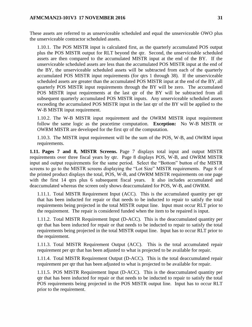
AFMCMAN23-101V3 17 NOVEMBER 2016 31
These assets are referred to as unserviceable scheduled and equal the unserviceable OWO plus
the unserviceable contractor scheduled assets.
1.10.1. The POS MISTR input is calculated first, as the quarterly accumulated POS output
plus the POS MISTR output for RLT beyond the qtr. Second, the unserviceable scheduled
assets are then compared to the accumulated MISTR input at the end of the BY. If the
unserviceable scheduled assets are less than the accumulated POS MISTR input at the end of
the BY, the unserviceable scheduled assets will be subtracted from each of the quarterly
accumulated POS MISTR input requirements (for qtrs 1 through 38). If the unserviceable
scheduled assets are greater than the accumulated POS MISTR input at the end of the BY, all
quarterly POS MISTR input requirements through the BY will be zero. The accumulated
POS MISTR input requirements at the last qtr of the BY will be subtracted from all
subsequent quarterly accumulated POS MISTR inputs. Any unserviceable scheduled assets
exceeding the accumulated POS MISTR input in the last qtr of the BY will be applied to the
W-B MISTR input requirement.
1.10.2. The W-B MISTR input requirement and the OWRM MISTR input requirement
follow the same logic as the peacetime computation. Exception: No W-B MISTR or
OWRM MISTR are developed for the first qtr of the computation.
1.10.3. The MISTR input requirement will be the sum of the POS, W-B, and OWRM input
requirements.
1.11. Pages 7 and 8, MISTR Screens. Page 7 displays total input and output MISTR
requirements over three fiscal years by qtr. Page 8 displays POS, W-B, and OWRM MISTR
input and output requirements for the same period. Select the “Bottom” button of the MISTR
screens to go to the MISTR screens displaying the “Lot Size” MISTR requirements. Page 8 of
the printed product displays the total, POS, W-B, and OWRM MISTR requirements on one page
with the first 14 qtrs plus 6 subsequent fiscal years. It also includes accumulated and
deaccumulated whereas the screen only shows deaccumulated for POS, W-B, and OWRM.
1.11.1. Total MISTR Requirement Input (ACC). This is the accumulated quantity per qtr
that has been inducted for repair or that needs to be inducted to repair to satisfy the total
requirements being projected in the total MISTR output line. Input must occur RLT prior to
the requirement. The repair is considered funded when the item to be repaired is input.
1.11.2. Total MISTR Requirement Input (D-ACC). This is the deaccumulated quantity per
qtr that has been inducted for repair or that needs to be inducted to repair to satisfy the total
requirements being projected in the total MISTR output line. Input has to occur RLT prior to
the requirement.
1.11.3. Total MISTR Requirement Output (ACC). This is the total accumulated repair
requirement per qtr that has been adjusted to what is projected to be available for repair.
1.11.4. Total MISTR Requirement Output (D-ACC). This is the total deaccumulated repair
requirement per qtr that has been adjusted to what is projected to be available for repair.
1.11.5. POS MISTR Requirement Input (D-ACC). This is the deaccumulated quantity per
qtr that has been inducted for repair or that needs to be inducted to repair to satisfy the total
POS requirements being projected in the POS MISTR output line. Input has to occur RLT
prior to the requirement.
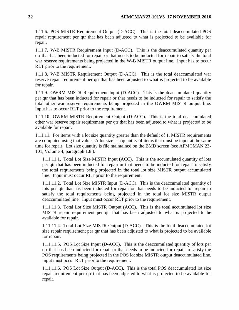
32 AFMCMAN23-101V3 17 NOVEMBER 2016
1.11.6. POS MISTR Requirement Output (D-ACC). This is the total deaccumulated POS
repair requirement per qtr that has been adjusted to what is projected to be available for
repair.
1.11.7. W-B MISTR Requirement Input (D-ACC). This is the deaccumulated quantity per
qtr that has been inducted for repair or that needs to be inducted for repair to satisfy the total
war reserve requirements being projected in the W-B MISTR output line. Input has to occur
RLT prior to the requirement.
1.11.8. W-B MISTR Requirement Output (D-ACC). This is the total deaccumulated war
reserve repair requirement per qtr that has been adjusted to what is projected to be available
for repair.
1.11.9. OWRM MISTR Requirement Input (D-ACC). This is the deaccumulated quantity
per qtr that has been inducted for repair or that needs to be inducted for repair to satisfy the
total other war reserve requirements being projected in the OWRM MISTR output line.
Input has to occur RLT prior to the requirement.
1.11.10. OWRM MISTR Requirement Output (D-ACC). This is the total deaccumulated
other war reserve repair requirement per qtr that has been adjusted to what is projected to be
available for repair.
1.11.11. For items with a lot size quantity greater than the default of 1, MISTR requirements
are computed using that value. A lot size is a quantity of items that must be input at the same
time for repair. Lot size quantity is file maintained on the BMD screen (see AFMCMAN 23-
101, Volume 4, paragraph 1.8.).
1.11.11.1. Total Lot Size MISTR Input (ACC). This is the accumulated quantity of lots
per qtr that has been inducted for repair or that needs to be inducted for repair to satisfy
the total requirements being projected in the total lot size MISTR output accumulated
line. Input must occur RLT prior to the requirement.
1.11.11.2. Total Lot Size MISTR Input (D-ACC). This is the deaccumulated quantity of
lots per qtr that has been inducted for repair or that needs to be inducted for repair to
satisfy the total requirements being projected in the total lot size MISTR output
deaccumulated line. Input must occur RLT prior to the requirement.
1.11.11.3. Total Lot Size MISTR Output (ACC). This is the total accumulated lot size
MISTR repair requirement per qtr that has been adjusted to what is projected to be
available for repair.
1.11.11.4. Total Lot Size MISTR Output (D-ACC). This is the total deaccumulated lot
size repair requirement per qtr that has been adjusted to what is projected to be available
for repair.
1.11.11.5. POS Lot Size Input (D-ACC). This is the deaccumulated quantity of lots per
qtr that has been inducted for repair or that needs to be inducted for repair to satisfy the
POS requirements being projected in the POS lot size MISTR output deaccumulated line.
Input must occur RLT prior to the requirement.
1.11.11.6. POS Lot Size Output (D-ACC). This is the total POS deaccumulated lot size
repair requirement per qtr that has been adjusted to what is projected to be available for
repair.

AFMCMAN23-101V3 17 NOVEMBER 2016 33
1.11.11.7. W-B Lot Size Input (D-ACC). This is the deaccumulated quantity of lots per
qtr that has been inducted for repair or that needs to be inducted for repair to satisfy the
war reserve requirements being projected in the W-B lot size MISTR output
deaccumulated line. Input must occur RLT prior to the requirement.
1.11.11.8. W-B Lot Size Output (D-ACC). This is the total deaccumulated war reserve
lot size repair requirement per qtr that has been adjusted to what is projected to be
available for repair.
1.11.11.9. OWRM Lot Size Input (D-ACC). This is the deaccumulated quantity of lots
per qtr that has been inducted for repair or that needs to be inducted for repair to satisfy
the other war reserve requirements being projected in the OWRM lot size MISTR output
deaccumulated line. Input must occur RLT prior to the requirement.
1.11.11.10. OWRM Lot Size Output (D-ACC). This is the total other war reserve
deaccumulated lot size repair requirement per qtr that has been adjusted to what is
projected to be available for repair.
1.12. Pages 9 and 10, Buy Operating Level Summary. Page 9 displays the buy operating
level summary for full funding. Page 10 displays the buy operating level summary for limited
funding. The full funding page is included in the printed copy of the SMCW. These pages
display the values, by pick-off point, for the maximum data elements (if applicable) of the buy
operating level, the applied assets, and the net over or net under position. The possible data
elements, applied assets, and computational results (Table 1.3) that can be displayed on the buy
operating level screens are as follows.
Table 1.3. Possible Data Elements Applied Assets and Computational Results.
1 Total Base Stk Lvl Depot Safety Lvl Total Ovhl Stk Lvl
2 Total JR Cndmn Base Cndmn OIM Rep Gens Cndmn
3 NJR Rep Gens Cndmn RDE Rep Gens Cndmn OIM Dep Rpr Cycle
4 NJR Dep Rpr Cycle RDE Dep Rpr Cycle Add Rqmt Non-Recur
5 XXXXXXX Pctm Dfct Add Rqmt Recur WRSK-BLSS Rqmt
6 XXX WRSK-BLSS Dfct OWRM Rqmt XXXXXXXXX OWRM Dfct
7 Total Buy Oper Lvl Svc Assets Svc Due In
8 Svc On Order TOC Assets Net Depot Unsvc Assets
9 Net Due-In Unsvc Net Over Position Net Short Position
1.13. Page 11, Computation Status. Page 11 is the computation status page that provides the
following informational results from the requirements computation of the individual item. This
information is also included in the printed copy of the SMCW.
1.13.1. Buy (Full) Quantity and Dollars. The buy quantity is the 3rd short position
(paragraph 1.8.83) at the buy point or at the term point, whichever is less. This is the full
buy deficit where no budget constraints have been applied to the AAM computation. The
buy quantity is multiplied by the forecast unit price to obtain the dollar value.
1.13.2. Buy (Ltd) Quantity and Dollars. The buy quantity is the 3rd short position
(paragraph 1.8.84) at the buy point or at the term point, whichever is less. This is the
limited buy deficit where budget constraints have been applied to the AAM computation.
The buy quantity is multiplied by the forecast unit price to obtain the dollar value.

34 AFMCMAN23-101V3 17 NOVEMBER 2016
1.13.3. Term Quantity and Dollars.
1.13.3.1. If the buy quantity is greater than zero, the termination quantity is zero.
1.13.3.2. If the buy quantity is zero and the total on-order assets (paragraph 1.8.44) is
zero, the termination quantity is zero.
1.13.3.3. SIRS calculates total assets by selecting each of the following quantities at the
term point and adding them together: serviceable assets (paragraph 1.8.42), on-order
assets (paragraph 1.8.44), net depot unserviceable assets (paragraph 1.8.60), TOC
assets (paragraph 1.8.57), due-in serviceable assets (paragraph 1.8.43), and net due-in
unserviceable assets (paragraph 1.8.78).
1.13.3.3.1. If the worldwide termination level (paragraph 1.13.8) is greater than or
equal to the total assets, the termination quantity is zero.
1.13.3.3.2. The termination quantity is equal to the total assets minus the termination
level. Next, the termination quantity is compared to the total on-order assets
(paragraph 1.8.44). When the total on-order assets are greater than the termination
quantity, the IMS/MM will terminate only those on-order assets equal to the
termination quantity. When the total on-order assets are less than the termination
quantity, SIRS reduces the termination quantity to equal the total on-order assets.
The termination quantity is multiplied by the unit price to get the dollar value. (See
AFMCMAN 23-101, Volume 1, Chapter 4 for termination guidance.)
1.13.4. Excess Quantity and Dollars. If the computed 3rd over quantity (paragraph 1.8.81)
at Retention is zero, then the excess quantity is zero. Else, SIRS computes the excess
quantity by comparing the 3rd over quantity at Retention with the select retention level
(paragraph 1.13.11), along with the serviceable assets at the term point (paragraph 1.8.42),
the due-in serviceable assets at the term point (paragraph 1.8.43), the total unserviceable
assets at the term point (paragraph 1.8.58), the TOC assets at the term point (paragraph
1.8.58), and total due-in unserviceable assets at the term point (paragraph 1.8.76).
1.13.4.1. If the select retention level is equal to the serviceable assets plus the due-in
serviceable assets, then the total of the unserviceable assets, the TOC assets, and the due-
in unserviceable assets is the excess quantity.
1.13.4.2. If the select retention level is less than the serviceable assets plus the due-in
serviceable assets, then the serviceable assets plus the due-in serviceable assets, plus the
unserviceable assets, plus the TOC assets, plus the due-in unserviceable assets, minus the
selection retention level, is the excess quantity.
1.13.4.3. If the select retention level is greater than the serviceable assets plus the due-in
serviceable assets, then SIRS compares the select retention level to the total of the
serviceable assets plus the due-in serviceable assets plus the TOC assets.
1.13.4.3.1. If the total of the serviceable assets plus the due-in serviceable assets plus
the TOC assets is equal to the select retention level, then the sum of the total
unserviceable assets and total due-in unserviceable assets is the excess quantity.
1.13.4.3.2. If the total of the serviceable assets plus the due-in serviceable assets, plus
the TOC assets is greater than the select retention level, then the serviceable assets
plus the due-in serviceable assets, plus the unserviceable assets, plus the TOC assets,

AFMCMAN23-101V3 17 NOVEMBER 2016 35
plus the due-in unserviceable assets, minus the selection retention level, is the excess
quantity.
1.13.4.3.3. Else, if the select retention level is equal to or greater than the sum of the
serviceable assets, the due-in serviceable assets, the TOC assets, the netted
unserviceable assets at the term point (paragraph 1.8.60) and the netted due-in
unserviceable assets at the term point (paragraph 1.8.78), then the excess quantity is
zero. Otherwise, the excess quantity is equal to the sum of the serviceable assets plus
the due-in serviceable assets, plus the TOC assets, plus the netted unserviceable assets
at the term point and the netted due-in unserviceable assets at the term point minus
the select retention level.
1.13.4.4. The excess quantity is multiplied by the unit price to obtain the excess dollar
value. If the excess dollar value is less than the uneconomic excess value on the Standard
Data Table (see AFMCMAN 23-101, Volume 2), then the excess quantity is added to the
select retention level and the excess quantity is reduced to zero.
1.13.5. Repair. The repair quantity is the total repair requirement computed MISTR Input
(ACC) at the end of the AY of the computation. The repair quantity is multiplied by the unit
repair cost to obtain the repair dollar value.
1.13.6. Worldwide Buy Operating Levels (Full). The buy operating level is an information
entry and consists of the requirements of an item reduced to replacements, condemnations, or
non-recurring (additive) data. This level contains both Air Force and FMS program
requirements picked off at the buy period. This level is also used to display the total gross
number of inventory spares required to support the item. The following elements are
selected at the buy period and added together: total base stock level, depot safety level, total
overhaul stock level, W-B requirement, OWRM requirement, additive requirements non-
recurring, OIM depot repair cycle requirement, NJR depot repair cycle requirement, and
RDE depot repair cycle requirement. To this subtotal are added the following data elements,
each accumulated through the buy period: total JR condemnations, base condemnations,
OIM Rep Gen condemnations, NJR Rep Gen condemnations, and RDE Rep Gen
condemnations. The full buy operating level is the requirement computed where no budget
constraints have been applied to the AAM computation.
1.13.7. Worldwide Buy Operating Levels (Ltd). The buy operating level is an information
entry and consists of all the requirements of an item reduced to replacements,
condemnations, or non-recurring (additive) data. This level contains both Air Force and
FMS program requirements picked off at the buy period. This level is also used to display
the total gross number of inventory spares required to support the item. The following
elements are selected at the buy period or term period, whichever is less, and added together:
total base stock level, depot safety level, total overhaul stock level, W-B requirements,
OWRM requirements, additive requirements non-recurring, OIM depot repair cycle
requirements, NJR depot repair cycle requirements, and RDE depot repair cycle
requirements. To this subtotal are added the following data elements each accumulated
through the buy period: total JR condemnations, base condemnations, OIM rep gen
condemnations, NJR rep gen condemnations, and RDE rep gen condemnations. The limited
buy operating level is the requirement computed where budget constraints have been applied
to the AAM computation.

36 AFMCMAN23-101V3 17 NOVEMBER 2016
1.13.8. Worldwide Term Level. The termination level is similar to the buy operating level in
that it consists of all the requirements of an item reduced to replacements, condemnations, or
non-recurring (additive) data. This level contains both Air Force and FMS program
requirements picked off at a point 12 months beyond the buy operating period. On-order
contract and PR/Military Interdepartmental Purchase Request (MIPR) assets excess to this
level will be shown as a termination quantity. On-order contract assets can be retained to this
level, whereas, quantities in the process of acquisition (PR/MIPRs) must be reduced to the
buy operating level (see AFMCMAN 23-101, Volume 4). This level is also used to
determine releasable assets to other Department of Defense agencies on a non-reimbursable
basis, or returned to production. The following data are each selected at the term point or
AY buy point, whichever is greater: total base stock level, depot safety level, total overhaul
stock level, W-B requirements, OWRM requirements, additive requirements non-recurring,
OIM depot repair cycle requirements, NJR depot repair cycle requirements, and RDE depot
repair cycle requirements. To this subtotal are added the following data elements each
accumulated through the buy period: total JR condemnations, base condemnations, OIM rep
gen condemnations, NJR rep gen condemnations, and RDE rep gen condemnations. If the
worldwide termination level is less than the worldwide buy operating level, the worldwide
termination level is increased to equal the worldwide buy operating level.
1.13.9. Worldwide Min Retention Level. The minimum retention level consists of the peak
stock levels and repair cycle at the peak demand rate, the balance computed requirements
reduced to condemnations and additives. Peak refers to the largest quarterly requirement
during the 39-qtr computation span (38 qtrs plus Retention). This level contains both Air
Force and FMS program requirements, and is used to determine on-hand assets to be
retained. To compute minimum retention level, add the following elements at the peak qtr:
total base stock level, depot safety level, total overhaul stock level, W-B requirements,
OWRM requirements, additive requirements non-recurring, OIM depot repair cycle
requirements, NJR depot repair cycle requirements, and RDE depot repair cycle
requirements. Then add the following data elements each accumulated through the buy
period: total JR condemnations, base condemnations, OIM rep gen condemnations, NJR rep
gen condemnations, and RDE rep gen condemnations. This computed minimum retention
level is adjusted using the Risk Factor, Base Reduction Factor, and Condemnation Factor for
the item on the File Maintenance (FM) RLAF Retention Level Adjustment Factor screen (see
AFMCMAN 23-101, Volume 2). Calculate the accumulated total condemnations as the total
of the following data elements accumulated through Retention: total JR condemnations, base
condemnations, OIM rep gen condemnations, NJR rep gen condemnations, and RDE rep gen
condemnations. From the computed minimum retention level, subtract the total
condemnations and subtract the additive requirements non-recurring at the peak. Take this
result times the risk factor, and add in the result from multiplying the accumulated total
condemnations times the risk factor times the condemnation factor. Finally, add the additive
requirements non-recurring at the peak, and round the result to get the adjusted minimum
retention level.
1.13.10. Worldwide Gross Retention Level. This is not displayed anywhere, but it is used to
adjust other levels. The gross retention level consists of the authorized Retention program
span computed at the demand rate plus additives. This level contains both Air Force and
FMS program requirements, and is used to determine on-hand assets to be retained. The total

AFMCMAN23-101V3 17 NOVEMBER 2016 37
net rep gens is computed as the OIM generations available from repair, the NJR generations
available from repair, and the RDE generations available from repair, each accumulated
through Retention. The accumulated total condemnations will be calculated as the total of
the following data elements accumulated through Retention: total JR condemnations, base
condemnations, OIM rep gen condemnations, NJR rep gen condemnations, and RDE rep gen
condemnations. If the repair cost is less than the unit price, the reduce factor is the repair
cost divided by the unit price rounded to three decimal places. Else the reduce factor is equal
to 1. The gross retention level is determined using the risk factor, base reduction factor, and
condemnation factor for the item on the FM RLAF Retention Level Adjustment Factor
screen (see AFMCMAN 23-101, Volume 2). The adjusted minimum retention level
(paragraph 1.13.9) is added to the total net rep gens times the reduce factor. That total is
added to the product of the OIM base repair cycle requirement times the reduce factor times
the base reduction factor to get the gross retention level. From the gross retention level,
subtract the accumulated total condemnations and subtract the additive requirements non-
recurring at the peak. Multiply this reduced gross retention level times the risk factor. To
the resulting gross retention level, add the product of multiplying the accumulated total
condemnations times the risk factor times the condemnation factor. Finally, add the additive
requirements non-recurring at the peak, and round the result to get the adjusted gross
retention level.
1.13.11. Worldwide Selection Retention Level. The selection retention level is determined
by comparing total serviceable assets to the worldwide minimum retention level and the
worldwide gross retention level. If the serviceable assets equal or exceed the gross retention
level, then the selection retention level is made equal to the gross retention level. If the
serviceable assets are less than the gross retention level but greater than the minimum
retention level, then the selection retention level is made equal to the serviceable assets. If
the serviceable assets are equal to or less than the minimum retention level, the selection
retention level is made equal to the minimum retention level. This selection retention level is
used to determine excess assets (see paragraph 1.13.4).
1.13.12. Distribution Levels. These levels are computed for output to D035A.
1.13.12.1. Control. The control level quantity is the same as the worldwide termination
level quantity. It is used to determine whether or not to release assets against
unprogrammed requisitions (requirements for those customers who have not been
included in the SIRS computation).
1.13.12.2. Support. The support level quantity is equal to one qtrs worth of the control
level quantity. This is calculated by counting the number of months between the start of
the computation and the termination period and dividing the result into the control level
quantity, rounding to an integer. It is used as a limit for the release of priority
programmed requisitions (requirements for those customers who have been included in
the SIRS computation).
1.13.13. Sources of Repair and Percents. All sources (organic and contractor), which
accomplish repair on the item, are displayed with the percent of repair accomplished at each
source. The percents of repair always total to 100%. AFMC Form 206, Temporary Work
Request, repairs are recorded as OT (other). The sources of repair are presented in Table 1.4

38 AFMCMAN23-101V3 17 NOVEMBER 2016
Table 1.4. Sources of Repair.
Symbol Definition
1 OC Oklahoma City-Air Logistics Complex (OC-ALC)
2 OO Ogden-ALC (OO-ALC)
3 WR Warner Robins-ALC (WR-ALC)
4 SA CCSD at San Antonio
5 CT Contractor
6 OT Other
7 UN Unknown
8 DM DMISA
1.13.14. Delivery Schedule. This entry provides the IMS/MM with a guide for peacetime
procurement action on the item. It is based on the Central Secondary Item Stratification
(CSIS) buy simulation. The following data elements are shown:
1.13.14.1. Pt Buy Init Date. The year and month in which procurement action will be
started. The computation calculates the peacetime buy initiation date, by taking the first
qtr where the third short occurs, then backing up the number of months of PCLT. The
default is the month after the asset’s cutoff date. So if the asset cutoff is March, then the
default date is April of that year.
1.13.14.2. Pt Buy Qty. The peacetime buy quantity is the quantity that will be placed on
order.
1.13.14.3. Del Begin Date. The simulated year and month when procurement deliveries
will begin.
1.13.14.4. Phased Del Qty. The simulated phased deliveries of the on-order quantity
through the buy period. Qtr 5 will represent the buy period qtrs. Qtrs 1 through 4
represent the four qtrs prior to the buy period quantity.
1.14. Page 12, I&S Family Members. Page 12 displays the entire I&S family, including the
order of use code. The middle digit of the order of use code designates the subgroup. The
highest middle digit is the most preferred and I&S family master. Additional members of a
subgroup are offset under the SGM. This information is printed as a separate page. It is possible
to change the order of use using the FM I&S Structure screen (see AFMCMAN 23-101, Volume
4, paragraph 1.15.).
1.15. Page 13, Application Data. Page 13 displays all of the applications for the item that were
input by the ES through the API (D200F), along with the associated data for that application as
used on that item. The data elements displayed are: application designator (the standard
program designator in API), 2-digit APSC, application MIEC, program development code, PBD,
QPA, and application percent.
1.16. Page 14, Deferrals Page. Displays any deferrals or adjustments to the computed
requirement.
1.16.1. Page 1 of the FM SMCW SGM Comp Worksheet Rqmts screen (see AFMCMAN
23-101, Volume 4) looks like page 14 of the Display SMCW screen. The IMS/MM can file
maintain the FMS Rqmt and FMS PR Qty. Documentation must be typed into the Notepad.

AFMCMAN23-101V3 17 NOVEMBER 2016 39
The selection “PUSH RDE TO PICA” is selected when the IMS/MM wants to send revised
projected recurring demands to the PICA from the March, June or December cycles (see
AFMCMAN 23-101, Volume 4, paragraph 9.2.2.).
1.16.2. This is part of the Buy Breakout and Signature page on the printed computation. The
IMS/MM will complete the page in the SMCW when the item is in a buy. Itemized deferrals
and total dollars requiring approval will be shown. Deferrals due to no actual experience
might be listed here as a memo entry. If the deferrals were not taken, enter the total deferred
quantity for the first replenishment requirements for deferrals and subtract the deferrals from
the AF POS Rqmt to get the scrubbed AF POS buy requirement, which is entered as AF POS
Rqmt. On the September cycle, the IMS/MM will use the quantities from the AY and WRM
columns to initiate the PR. If on the following March cycle, the CY requirement (that
portion of the requirement that represents 31 March to 30 September) is decreased, the
IMS/MM may protect the initiated PR quantity up to the remaining CY requirement plus the
AY requirement. Any requirements, which exceed the AY requirement, must be reduced out
of the PR. Additional CY requirements may be initiated from the March cycle; however, no
BY requirements may be initiated from the March cycle.
1.17. Page 15, Coding and Approval. Page 15 displays the Automated Budget Compilation
System (ABCS) action codes and approval levels. This screen will not be used. This is part of
the Buy Breakout and Signature page on the printed computation. The IMS/MM will complete
this page in the SMCW. Reference Table 1.5 Note: Some organizations have developed a
signature page that is attached on top of the computation, recomputation or INS/INS Item Status
Listing. This product may be used in lieu of the computation, recomputation or INS/NSO Item
Status Listing as long as the current date appearing on the D200A product appears on the
signature page.
Table 1.5. Proration Technique for Buy and Termination Periods.
Formula
1 Step 1: Lead Time Proration = (11 - 9)/3 = .6667
2 Step 2: Buy Qtr Minus Prior Qtr = Difference
3 Step 3: Difference x Lead Time Proration (Step 1) = Results
4 Step 4: Results (Step 3) + Prior Qtr = Buy Period Qty

40 AFMCMAN23-101V3 17 NOVEMBER 2016
Chapter 2
ITEM RECOMPUTATIONS
2.1. Introduction. This chapter describes the procedures for the two types of item
recomputations. From the SIRS dropdown menu, select FM, then select Menu. On the SIRS FM
menu there is a selection for FRIR (“For Real” Item Recomp) and a selection for WTIR (“What
If” Item Recomputation). The FM FRIR screen is used to initiate a computation on an individual
item, using file maintained data element values to update the computation results that can be
viewed online in SIRS. The WTIR is used to temporarily change data elements on a
“simulation” database and produce results that can only be seen on a hard copy product. Neither
recomputation updates data sent to interfacing systems including CSIS. Only data resulting from
a SIRS computation (Initial, Final, and Summary) are used to update CSIS.
2.2. “For Real” Item Recomputation.
2.2.1. Any OPR, IMS/MM, PMS, or ES who has a valid SIRS FM password/ID can initiate
“For Real” item recomputations. This recomputation uses the data on the SIRS database,
including any data that was just file maintained. A recomputation, just like FM, can only be
done between the Initial and Final computations, and the Final and Summary computations.
FM and the recomputation cannot be done between the Summary computation and the next
cycle’s Initial computation.
2.2.2. After the user has completed FM, access the FM FRIR, SIRS FM FRIR. Type the
SGM stock number. Selection of any of the output products is optional. By typing an “X”
(non-Graphic User Interface (GUI)) or clicking on the box (GUI) by the product, the user
may select the SMCW, the SGM OWRM Computation Worksheet or the Factors/Usage
Printout. The message “START RECOMP? CONFIRM Y/N” will appear. The message
“RECOMPUTE SAFETY LEVELS? (Y/N)” will appear. If the user responds “Y” for yes,
safety levels are recomputed; else if the user responds “N” for no, the previously computed
safety levels are used in the re-computation. If an output product was requested, the message
“JOB (number) HAS BEEN REQUESTED” will appear. Item re-computations are
processed as required with SIRS output products provided to the requester within 30 minutes.
If an output product was not requested, the message “ITEM RECOMP COMPLETED” will
appear. Either message is an indication that the request for a “For Real” item recomputation
was successful and the SIRS database now reflects the use of file maintained data element
values in the computed results. The results of the “For Real” item re-computation are
available for online viewing upon the successful completion of the re-computation request.
2.2.3. An item with a no compute code of “N” or an obsolete item cannot be changed
through the SIRS process to a demand-based, INS, NSO, or military contingency item. An
INS item cannot be changed to computing in D200A. INS items can only be changed via
change to the Acquisition Advice Code (AAC) in D043 and subsequent cycle interface of
D043 with D200E (RIID). To change an NCO item to active, the IMS/MM must access
BMD screen, file maintain a “B” in the category code field, and document the reason. Note:
Both INS and NSO items can be recomputed.
2.2.4. When a “For Real” re-computation is performed, a message is displayed on the ES
Review List (see AFMCMAN 23-101, Volume 5, paragraph 5.2.) of all of the immediate

AFMCMAN23-101V3 17 NOVEMBER 2016 41
next lower assemblies, notifying the ESs that their NHA MISTR programs may have
changed.
2.3. “What If” Item Recomputation.
2.3.1. The “What If” item recomputation is a simulated computation and does not
permanently change any SIRS data element, nor is the data used to update CSIS. When an
error is not corrected during the FM process prior to the SIRS Summary computation or
when the IMS/MM or ES wants to see the impact of a management decision on the item, the
IMS/MM, PMS, or ES can request a “What If” item recomputation to simulate the
computational results with the corrected or projected data elements.
2.3.2. An item with a no compute code of “N” or an obsolete item cannot be changed
through the SIRS process to a demand-based, INS, NSO, or military contingency item. An
INS item cannot be changed to a computing item. The user can explore possibilities in
simulation mode only, by using a similar item that already is computing and then changing
all the necessary data. Great care must be taken to ensure that all the data is corrected,
especially future programs, rates/percents, etc.
2.3.3. Any OPR, IMS/MM, PMS, or ES that has a valid FM password/user identifier can
initiate “What If” item recomputations. From the SIRS FM menu, select WTIR, SIRS FM
WTIR. Then on the FM WTIR “What If” Item Recomputation screen, type the SGM, the “as
of” date, and select at least one output product. The user can get the SMCW, the SGM
OWRM Computation Worksheet, the Factors/Usage Printout, the INS/NSO Item Status
Listing, the MISTR Repair and Repair Data Report, the Budget CSIS, and the Repair CSIS.
The Budget and Repair CSIS products are available only between the Final and Summary
computations. The “What If” item recomputation results are not displayed online.
2.3.4. Selecting one of the output products listed above brings up the FM IRFM Item
Recomputation FM menu, listing all the “What If” simulation screens. The simulation
screens are images of the regular FM screens, but reflect an “S” in the front part of the screen
designator to indicate simulation. The “S” causes SIRS to only use the changed data to
produce the “What If” results and does not result in a permanent change to any SIRS data
element. The 13 “What If” simulation screens available for simulated changes are described
in paragraph 2.4. through 2.15 Select the simulation screen and add the changed data
2.3.5. After file maintaining all the data on the simulation screens, go back to the IRFM
menu and select SIR START ITEM RECOMP. The WTIR screen is displayed again. The
message “START RECOMP? CONFIRM Y/N” will appear. The message “RECOMPUTE
SAFETY LEVELS? (Y/N)” will appear. If the user responds “Y” for yes, safety levels are
recomputed; else if the user responds “N” for no, the previously computed safety levels are
used in the re-computation. The message “JOB (number) HAS BEEN REQUESTED” will
be displayed. SIRS does the recomputation, and provides the output products displaying the
results. If the user changes the SGM before submitting the recomputation, SIRS asks the
user to choose whether to discard the previous FM or continue. The user cannot start a new
recomputation until the previous one is processed or discarded. If the user leaves the SIRS
system before submitting the recomputation, all FM is discarded.
2.3.6. “What If” item recomputations must not be used as a substitute for timely FM. The
use of “What If” computations in lieu of the SIRS Summary computation must be

42 AFMCMAN23-101V3 17 NOVEMBER 2016
documented on the SIRS “What If” Item Recomputation. The SIRS Notepad is not available
from the WTIR screen nor is this Notepad available after the Summary computation is run.
“What If” item recomputations can be initiated any time, but will not be run at the same time
as a SIRS computation is running.
2.4. Simulation Additives. The FM SADR Simulation Additive Requirements screen provides
the capability to update any of the additive requirements that can be file maintained in the SIRS.
DOTM is updated on the Non Time Phased Asset screen. The user can make multiple selections
on the SADR screen. SIRS will display each screen, left to right, top to bottom. The same FM
rules for phasing and straight-lining quarterly entries also apply to the data on this simulation
screen. Type over the existing value. The file maintained value is straight-lined into all
subsequent qtrs where the values were equal to the original value prior to FM. The first value
that is different stops the straight-lining. To change selected qtrs but not all qtrs with the same
value, FM of the new value must be done in the first qtr to be changed and the original value
must be entered in the qtr that is to remain unchanged to stop the straight-lining at that qtr (see
AFMCMAN 23-101, Volume 4, paragraph 5.3.6.). The additive requirements that can be
simulated are as follows in Table 2.1
Table 2.1. SADR Screen - Additive Requirements That Can Be Simulated.
Additive Requirements Data Elements
1 Mission directed
2 Test stands
3 W-B Requirements (RSPs)
4 Mobile training units
5 War Consumable Distribution Objective (WCDO)
6 OWRM requirements
7 Retrofit-modification
8 RDE non-recurring requirements
9 RDE recurring requirements
10 Bench mock-up
11 Special program requirements
12 FMS H-coded backorders
13 Government Furnished Aerospace Equipment/Government Furnished
Materiel/Government Furnished Property (GFAE/GFM/GFP)
14 Special projects
15 FMS requirements
16 Initial installations
17 Support equipment
18 HPMSK
19 Cartridge Activated Device/Propellant Activated Device (CAD/PAD)
20 Turn-Around Spares Kit (TASK)
21 Retail Economic Order Quantity (EOQ)
22 Life limited requirement

AFMCMAN23-101V3 17 NOVEMBER 2016 43
2.5. Simulation Adjusted Levels. The FM SALV Simulation Adjusted Level Verification
Worksheet Selection screen provides the capability to change any of the adjusted levels by
SRAN. The same FM rules for adjusted levels also apply to the data on this simulation screen
(see AFMCMAN 23-101, Volume 4, paragraph 4.5.).
2.6. Simulation Basic Management Data (SBMD). The FM SBMD Simulation BMD screen
provides the capability to change selected data elements on the BMD screen (see Table 2.2). If
an item is changed to a Life Of Type Buy (LOTB) item, the life of type additive is computed and
added into the non-recurring additive requirement. If an item is changed back to a regular item,
the LOTB additives are deleted and removed from the total non-recurring additive requirement.
The same rules for FM of each of the below data elements apply to the simulation screen (see
AFMCMAN 23-101, Volume 4, Chapter 1).
Table 2.2. SBMD Screen Data Elements That Can Be Changed.
BMD Data Elements
1 Item name
2 Budget code, including SMC and MPC
2 Item category
3 Activity code
4 Safety level exclusion indicator
5 Weapon system life
6 Actual unit price
7 DOLP
6 ICS/RIW code
8 ICS/RIW expiration date
9 Deferred disposal code
10 Deferred disposal level
11 OWRM exclusion indicator
12 Lot size quantity
13 Minimum depot stock level
2.7. Simulation Factors. The FM SFAD Simulation Factor Data screen provides the capability
to change the factors data. The rates and percents can be simulated for any or all of the current
or 1st through 5th forecasts by typing over the existing value. For the TOIMDR, all positions of
the field must be filled, including the decimal (e.g., 0.0500 or 1.1200). The factor indicator code
must be compatible with the FM. Enter “Y” in any current through fifth forecast factor to revert
that field to the value indicated by the corresponding factor indicator code position (see
AFMCMAN 23-101, Volume 5, paragraph 2.26.). If any element in any year is file maintained,
the field is updated and the SRCs of all following element/forecast year combinations are
updated to “E.” If the user file maintains a factor indicator code that overrides estimates, the
corresponding fields (all forecast years) on the screen are changed in accordance with the factor
indicator. If the factor indicator is file maintained at the same time as the corresponding element
and the selected factor indicator does not allow for estimate values, an error message is
displayed. If the user inputs a factor indicator of “P” and the corresponding element FM does
not exceed the 8 qtr Moving Average History (MAH) value, SIRS defaults to the 8 qtr MAH
value. If the base RTS exclusion indicator is changed to an “X,” the base NRTS percent field is
set to 100, and base condemnations percent is set to zero for all forecast years. If the base RTS

44 AFMCMAN23-101V3 17 NOVEMBER 2016
exclusion indicator is changed to from an “X” to a blank, SIRS computes values for the base
NRTS percent and base condemnations percent fields. If the base RTS exclusion indicator is
“X” and the user file maintains those fields, an error message is displayed.
2.8. Simulation I-S Additive Requirements. The FM SIAR Simulation I-S Additive
Requirement screen allows the user to input and update interchangeable and substitute (I-S)
additive requirement data by SGM from the first comp qtr to the 39th qtr for “What If” item
recomputations. There are six I-S additive requirements. The user can select multiple I-S
additive requirements. The system processes the selections from left to right and top to bottom.
The first selection with an “X” is displayed and the corresponding element name is displayed in
the middle of the screen right above the quarterly values that are associated with it. The user can
also update one I-S additive requirement and its corresponding limit (LIM) I-S additive
requirement with the same values at the same time by entering these two I-S additive
requirement indicators with “X.” If the Enter key is pressed without a FM action, the screen
displays the next selection. The “X” in the selection field is removed once the element FM data
is displayed on the screen. The straight-lining techniques that the system uses when FM is done
depends on the way the values are entered. The FM value is straight-lined into all subsequent
qtrs where the values were equal to the original value prior to FM. The first value that is
different stops the straight-lining. To change selected qtrs but not all qtrs with the same value,
FM of the new value must be done in the first qtr to be changed and the original value must be
entered in the qtr that is to remain unchanged. This stops the straight-lining at that qtr. To
change data, type “X” in selected additive requirement fields.
2.9. Simulation Item Programs. The FM SIPD Simulation Item Program Data Product
Selection screen provides the capability to change past, future peacetime, and war program data.
Past programs should not usually be changed. Type “F” (future peacetime), “P” (past), or “W”
(future war), the standard program designator (application), program type (1 - hours, 2 -
squadron months, 3 - equipment months, 4 - PDM, 5 - aircraft sorties, 6 - EOHs, 7 - drone
recoveries, 8 - ammo expenditures, and 9 - MISTR), and Service code (A for Air Force). The
program data screen is displayed. If data is not found, zeros are displayed. Both peace and war
programs are displayed by qtrs. When updating war data, enter 3 months’ worth of program data
into the field for the qtr. SIRS will compute the item installed programs needed for the
computation. The QPA, application percent, and PBD for the application cannot be changed.
2.10. Simulation Non Time-Phased Assets. The FM SNTP Simulation Non Time-Phased
Assets screen provides the capability to change the serviceable, unserviceable, and TOC assets
for purpose code 0A, and to change the DOTM requirements (See Table 2.3). Type over the
existing values. If the user updates the on loan assets, then SIRS computes the on load additive
as equal to the on loan assets.

AFMCMAN23-101V3 17 NOVEMBER 2016 45
Table 2.3. SNTP Screen Data Elements by Asset Category That Can Be Changed.
Serviceable Assets Unserviceable Assets Other
1 Base/Depot Base TOC Assets
2 WRSK/BLSS Depot DOTM requirements
3 OWRM OWRM
4 Contractor Contractor
5 On loan OWO
6 Intransit Intransit
2.11. Simulation Pipeline Data Screen. The FM SPLD Simulation Pipeline Data screen
provides the capability to change simulated pipeline data and lead time days. The ALT and PLT
months, the total depot repair cycle days and the NJR depot repair cycle lead time days, both
regular and time-phased, cannot be simulated, as they are derived data elements. If the base
repair cycle days are entered and the current base NRTS percent is equal to 100, a message is
displayed that the base repair cycle days should be zero. If the time-phased depot repair cycle
effective date is changed to zero, then all time-phased fields are set to zero. If the time-phased
depot repair cycle date is zero and the user enters values in any of the time-phased fields, a
message is displayed that the date must be entered. The date must not be before the asset cutoff
date, and must end in 03, 06, 09, or 12. All the rules for FM also apply to the data elements on
this simulation screen (see AFMCMAN 23-101, Volume 4, Chapter 3). Enter “Y” to change
the file maintained values to the actual values from the interfacing systems. Enter “Z” to change
to the default values. A warning message is displayed when the file maintained value exceeds
the corresponding data element in the Standard Data Table (see AFMCMAN 23-101, Volume 2).
A warning message is displayed when the file maintained value for base O&ST days or base
repair cycle days exceeds the corresponding default value by 10 days and base repair processing
days exceeds the corresponding default value by 3 days.
2.12. Simulation MISTR Repair and Repair Data. This menu contains all combinations of
SOR, production or contract number, and Contract Line Item Number (CLIN) for the SGM. The
combinations can be selected for FM, or a combination can be added. To view data, type an “X”
next to the desired selection. To add a Current Stock Number (CSN)/SOR/production/contract
number/CLIN, type an “A” in the selection field. Type the CSN, SOR, production/contract
number, and CLIN to be added. To delete a CSN/SOR/production/contract number/CLIN, type a
“D” next to the desired selection. To file maintain a SOR percent, type a “C” next to the desired
selection and change the value of the SOR percent to what is desired. Note: All SOR percents
for the SGM must total 100, so multiple SOR percents must be changed. Scrolling may be used
to perform this function when multiple SOR percents need to be changed on different pages.
2.13. Simulation Time-Phased Assets. The FM STPA Simulation Time-Phased Assets screen
provides the capability to update any of the time-phased due-in and on-order assets that can be
file maintained in the SIRS. The user can make multiple selections on the STPA screen. SIRS
will display each screen, left to right, top to bottom. As the user updates the screen, SIRS
displays the next screen that was selected. Type over the existing values. The fields can be a
valid number of “Ys” to revert to the actual data input from the interfacing system. For more
information about the time-phased assets, see AFMCMAN 23-101, Volume 4, paragraphs 6.8.
and 6.9.

46 AFMCMAN23-101V3 17 NOVEMBER 2016
2.14. Simulation Usage. The FM SUSD Simulation Usage Data screen provides the capability
to update any of the usage that can be file maintained in the SIRS. The user can make multiple
selections on the SUSD screen. SIRS will display each screen, left to right, top to bottom. Type
over the existing values. SIRS displays the next screen that was selected. Any or all of the eight
qtrs for each type of usage can be changed. The simulation of usage will cause SIRS to
recompute the rates and percents before using them in the “What If” item recomputation. The
past program resident in SIRS will be used in conjunction with the simulated past usage to
develop the simulated rates and percents, but the past program cannot be simulated. The rules
for FM also apply to the below data elements (Table 2.4) on this simulation screen (see
AFMCMAN 23-101, Volume 4 and AFMCMAN 23-101, Volume 5, paragraph 1.12.).
Table 2.4. SUSD Screen Data Elements That Can Be Changed.
SUSD Screen Data Elements
1 Base condemnations
2 Base NRTS
3 Base RTS
4 MISTR condemnations
5 Depot condemnations (total)
6 Depot rep gens (MISTR repairs) (total for the SGM)
2.15. Simulation War Data. The FM SWD Simulation War Data screen provides the
capability to change the war rates and percents, war pipeline days, war adjustment factor, Work
Unit Code (WUC), floating stock level (no longer used), and number of users used in the
OWRM computation. The rules for FM also apply to the data elements on this simulation screen
(see Chapter 4). File maintained values are validated against the OWRM Table (see
AFMCMAN 23-101, Volume 2). If the updated values exceed those standards, a warning
message is displayed. SIRS will not allow the updated values to exceed the peacetime values,
and when this occurs, SIRS assigns the peacetime value. The user can enter “Zs” to revert to a
default value. If the file maintained value is a factor other than the TOIMDR, file maintained
“Zs” replace the value with the peacetime value from the EY time period.

AFMCMAN23-101V3 17 NOVEMBER 2016 47
Chapter 3
SAFETY LEVELS PRODUCTS
3.1. Introduction. This chapter describes the SIRS screens and products that display
information from the AAM computation. These products are usually provided to the AFMC
SIRS OPR, AFSC/LGPS. A discussion of the methodologies used to compute the safety level
requirement segment for SIRS is provided in a technical paper found via path
https://www.ripit.wpafb.af.mil/A4YR/D200A.asp, D200A Related Information, Aircraft
Availability.
3.2. Aircraft Availability Model Products. The AAM products can be accessed by selecting
AAM Aircraft Availability Model Data from the SIRS DIS MENU or from the SIRS DIS
AAMD MENU. The Display AAMD screen allows the user to select and view any of the
screens listed (see paragraph 3.2.1, 3.2.2., 3.2.3., 3.2.4., 3.2.5., and 3.2.6 below). To request
hard copy products, select SIRS OP-AAMR, then select the desired product using the selection
criteria displayed on this screen. The hard copy products are described in paragraph 3.2.7.
through 3.2.13
3.2.1. Display AAMO AAM OWRM Summary Results Screen. This screen displays the
OWRM data that is updated by the AAM during the Initial, pre-final, Final, pre-summary,
and Summary computations. Enter the AS OF date, TM PER (time period), MD (Mission
Designator) (such as C005 or blank for all MDs), the RUN PT (computation cycle), and three
targets. Four of the seven availability targets are displayed at a time. The user may select the
three targets to be displayed by entering 1, 2, 3, 5, 6, or 7. The defaults are 1, 2, and 3. The
fourth target is always displayed. For ACQ (acquisition), the value must be blank for
replenishment data or “X” for acquisition data. The default is blank for replenishment. Use
the scrolling commands to see all the data. The WRM is computed by subtracting the POS
Buy from the TOT CST FOR ACFT AVAL (total cost for aircraft availability). OWRM is
computed by subtracting W-B Buy from WRM. If the MD is left blank, the last page will
display “all aircraft” and CO MARG AVAL (Cut off Margin Available) is not displayed.
3.2.2. Display ADMD Additive Quantity/Cost by MD Screen.
3.2.3. Display BYMD Aircraft Availability by MD Screen. This screen displays, by MD,
the number of available aircraft, goals percentages, and dollar costs calculated by the AAM.
This data is not available on the Initial computation. Enter the AS OF date, RUN PT, FND
ENVIR (funding environment which is “LIM” for limited funding, or the default “Full” (for
peace) or “War1” through “War7” (default “War4” for war), TM PER, MD, and
PEACE/WAR IND. The war funding levels (War1, War2, etc.,) are calculated only for the
pre-final and pre-summary computations. If the peace/war indicator is equal to “P,” then the
TM PER can only be “2nd” for second qtr data, “BUY” for buy point data (the default),
“TERM” for termination point data, or “POM” for Program Objective Memorandum point
data. If the peace/war indicator is equal to “W,” then the TM PER can only be 1st, 4th, 7th,
or 10th (the default). For ACQ, the value must be blank for replenishment data or “X” for
acquisition data. The default is blank for replenishment. If the MD field is blank, all MDs
can be viewed by using the scrolling commands. The screen will display a message if no
data is found for the criteria entered. The projected number of aircraft (NR ACFT

48 AFMCMAN23-101V3 17 NOVEMBER 2016
PROJECTED) is the actual number of aircraft (NR ACFT ACTUAL) multiplied by the
decimal format aircraft available assessment (ACFT AVAIL ASSESSMENT). The MD
NON-SAFETY LEVEL is the sum of the NEGATIVE ASSETS, PIPELINE, INS-NSO
LEVEL, INITIALIZED STOCK LEVELS, and SPECIAL LEVELS.
3.2.4. Display MDFR Acft Aval/Fill Rate Goals Screen. This screen displays the list of
peacetime and wartime aircraft availability full and limited funding fill rate goals which are
updated during the Initial, pre-final, Final, pre-summary, and Summary computations. When
the PEACE/WAR IND is equal to “P,” then the headers are 2ND QUARTER, BUY POINT,
TERM POINT, and POM POINT. If the peace/war indicator is equal to “W,” then the
headers are MONTH 1, MONTH 4, MONTH 7, and MONTH 10. The aircraft availability
goal is a fill rate goal for an MD. The data is arranged by MD in ascending order. Use the
scrolling commands to view all data.
3.2.5. Display OPT One Percent Table Screen. This screen displays the replenishment and
acquisition cost associated with achieving different availabilities for full and limited funding
that is updated during the Initial, pre-final, Final, pre-summary and Summary computations.
FUL displayed in the SEL AVAIL field denotes the cost to achieve the full funding target;
LIM denotes the cost to achieve the limited funding target; and BTH denotes the cost to
achieve the target where the full and limited funding targets are the same. Enter the AS OF
date, MD (or blank for all MDs), TM PER, RUN PT, and PEACE/WAR IND. If the
peace/war indicator is equal to “P,” then the TM PER can only be “2nd” for second qtr data,
“BUY” for buy point data (the default), “TERM” for termination point data, or “POM” for
POM point data. If the peace/war indicator is equal to “W,” then the TM PER can be only
1ST, 4TH, 7TH or 10TH (the default). Use the scrolling commands to see all the data.
3.2.6. Display PIL Problem Item List Screen. This screen displays the problem item list for
an MD and time period combination that is updated during the pre-final, Final, pre-summary,
and Summary computations. No data is available from the Initial computation. All items are
displayed for the MD with a component availability (CMPNT AVAIL) less than or equal to a
standard component availability cutoff (CO CMPNT AVAIL). This standard component
availability cutoff is displayed at the top of screen and can be file maintained on the File
Maintenance SDT Standard Data Table (see AFMCMAN 23-101, Volume 2, paragraph
3.23.). Also displayed are the Line Replacement Units (LRUs) and Shop Replacement Units
(SRUs) based on the value in the LRU/SRU IND field. An “L” indicates an LRU and an “S”
indicates an SRU. If an LRU/SRU group is continued on more than one screen, the data for
the LRU is displayed as the first data line of the following screen. The data for the remaining
SRUs is displayed after the data for the LRU. The user may also view the indenture level
(INDENT LVL) and CMPNT AVAIL for each item. If no records are found for the selection
criteria, a message is displayed indicating no data found. Enter the AS Of date, RUN PT,
TM PER, MD (or blank for all MDs), and P/W IND (“W” for war, or “P” for peace, the
default). If the peace/war indicator is equal to “P,” then the TM PER can only be “2ND” for
second qtr data, “BUY” for buy point data (the default), “TERM” for termination point data,
or “POM” for POM point data. If the peace/war indicator is equal to “W,” then the TM PER
can be only 1ST, 4TH, 7TH or 10TH (the default). Use the scrolling commands to see all the
data.
3.2.7. Output Products. Each of the following products are automatically generated from the
Final and Summary computations and provided to the AFMC SIRS OPR (AFSC/LGPS).
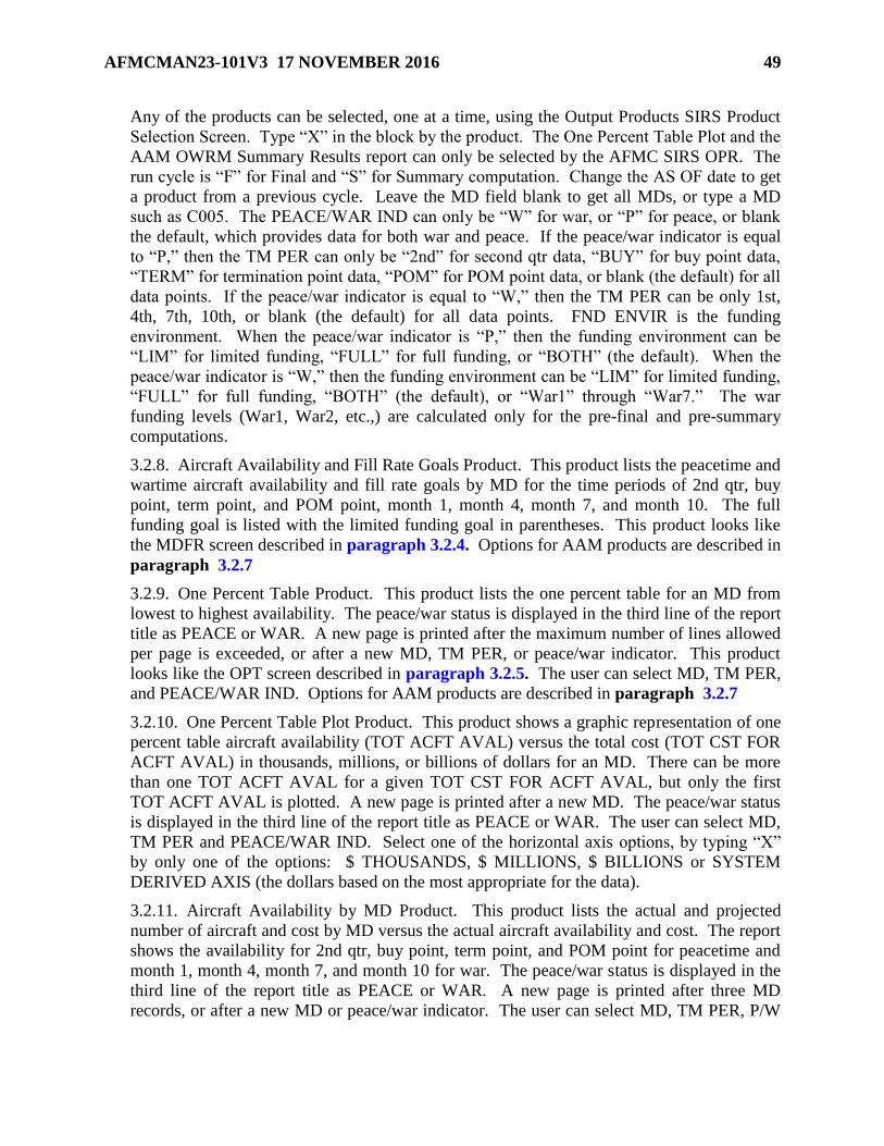
AFMCMAN23-101V3 17 NOVEMBER 2016 49
Any of the products can be selected, one at a time, using the Output Products SIRS Product
Selection Screen. Type “X” in the block by the product. The One Percent Table Plot and the
AAM OWRM Summary Results report can only be selected by the AFMC SIRS OPR. The
run cycle is “F” for Final and “S” for Summary computation. Change the AS OF date to get
a product from a previous cycle. Leave the MD field blank to get all MDs, or type a MD
such as C005. The PEACE/WAR IND can only be “W” for war, or “P” for peace, or blank
the default, which provides data for both war and peace. If the peace/war indicator is equal
to “P,” then the TM PER can only be “2nd” for second qtr data, “BUY” for buy point data,
“TERM” for termination point data, “POM” for POM point data, or blank (the default) for all
data points. If the peace/war indicator is equal to “W,” then the TM PER can be only 1st,
4th, 7th, 10th, or blank (the default) for all data points. FND ENVIR is the funding
environment. When the peace/war indicator is “P,” then the funding environment can be
“LIM” for limited funding, “FULL” for full funding, or “BOTH” (the default). When the
peace/war indicator is “W,” then the funding environment can be “LIM” for limited funding,
“FULL” for full funding, “BOTH” (the default), or “War1” through “War7.” The war
funding levels (War1, War2, etc.,) are calculated only for the pre-final and pre-summary
computations.
3.2.8. Aircraft Availability and Fill Rate Goals Product. This product lists the peacetime and
wartime aircraft availability and fill rate goals by MD for the time periods of 2nd qtr, buy
point, term point, and POM point, month 1, month 4, month 7, and month 10. The full
funding goal is listed with the limited funding goal in parentheses. This product looks like
the MDFR screen described in paragraph 3.2.4. Options for AAM products are described in
paragraph 3.2.7
3.2.9. One Percent Table Product. This product lists the one percent table for an MD from
lowest to highest availability. The peace/war status is displayed in the third line of the report
title as PEACE or WAR. A new page is printed after the maximum number of lines allowed
per page is exceeded, or after a new MD, TM PER, or peace/war indicator. This product
looks like the OPT screen described in paragraph 3.2.5. The user can select MD, TM PER,
and PEACE/WAR IND. Options for AAM products are described in paragraph 3.2.7
3.2.10. One Percent Table Plot Product. This product shows a graphic representation of one
percent table aircraft availability (TOT ACFT AVAL) versus the total cost (TOT CST FOR
ACFT AVAL) in thousands, millions, or billions of dollars for an MD. There can be more
than one TOT ACFT AVAL for a given TOT CST FOR ACFT AVAL, but only the first
TOT ACFT AVAL is plotted. A new page is printed after a new MD. The peace/war status
is displayed in the third line of the report title as PEACE or WAR. The user can select MD,
TM PER and PEACE/WAR IND. Select one of the horizontal axis options, by typing “X”
by only one of the options: $ THOUSANDS, $ MILLIONS, $ BILLIONS or SYSTEM
DERIVED AXIS (the dollars based on the most appropriate for the data).
3.2.11. Aircraft Availability by MD Product. This product lists the actual and projected
number of aircraft and cost by MD versus the actual aircraft availability and cost. The report
shows the availability for 2nd qtr, buy point, term point, and POM point for peacetime and
month 1, month 4, month 7, and month 10 for war. The peace/war status is displayed in the
third line of the report title as PEACE or WAR. A new page is printed after three MD
records, or after a new MD or peace/war indicator. The user can select MD, TM PER, P/W

50 AFMCMAN23-101V3 17 NOVEMBER 2016
IND and FND ENVIR. This product looks like the BYMD screen described in paragraph
3.2.3. Options for AAM products are described in paragraph 3.2.7
3.2.12. Problem Item List Product. This product looks like the PIL screen described in
paragraph 3.2.6. Options for AAM products are described in paragraph 3.2.7
3.2.12.1. The product automatically produced from the Final and Summary
computations, lists all the problem items for 2nd qtr, buy point, term point, and POM
point for peacetime and month 1, month 4, month 7, and month 10 for war. With each
MD, the LRU/SRU groups are listed in the order of the LRU’s component availability,
from lowest to highest. The LRU data appears first then the SRUs appear in site code
and NSN order. A blank line separates each LRU/SRU group from the next one. The
LRU data is repeated if the SRU data takes more than one page. Also listed are the Site
ID, SGM (SGM stock number), SMC (for the item), LRU/SRU IND (“L” indicates an
LRU and an “S” indicates an SRU), INDENT LEVL (indenture level), CMPNT AVAIL
(component availability), SYS EBO (system estimated back order), INV LEV
(investment level), and U-P FCST (FUP). A new page is printed after a new TM PER,
FUND EVIR, MD or a new peace/war indicator.
3.2.12.2. When this product is selected by the user, the report shows all items for the MD
with a component availability (CMPNT AVAIL) less than or equal to a standard
component availability cutoff (CO CMPNT AVAIL). If the user selects a CO CMPNT
AVAIL greater than the standard component availability cutoff that was file maintained
on the SDT Standard Data Table (see AFMCMAN 23-101, Volume 2, paragraph 3.23.),
the value on the SDT table is used. The list is in indenture level/component availability
sequence. The user can select MD, TM PER, Peace/War IND, FND ENVIR (funding
environment) and CO CMPNT AVAIL.
3.2.13. AAM OWRM Summary Results Product. This product lists the OWRM aircraft
availability versus cost by MD which contains a breakdown of the total cost for seven
availability targets. A new page is printed after the maximum number of lines allowed per
page is exceeded by TM PER and after three MDs. The summary report only applies if the
user leaves the MD field blank. The user requested OWRM aircraft availability versus cost
by MD summary report is specific to the TM PER value. The user can select MD and TM
PER. The TM PER can be only 1ST, 4TH, 7TH, 10TH, or blank. The default is a blank
representing all TM PERs, which are the limited funding, full funding, and the seven war
funding levels. The war funding levels are only calculated for the pre-final and pre-summary
computations. This product looks like the Display AAMO AAM OWRM Summary Results
screen described in paragraph 3.2.1. Options for AAM products are described in
paragraph 3.2.7

AFMCMAN23-101V3 17 NOVEMBER 2016 51
Chapter 4
OTHER WAR RESERVE MATERIEL
4.1. Introduction. AFI 25-101, War Reserve Materiel (WRM) Program Guidance and
Procedures, sets the policies and responsibilities for managing WRM. OWRM are reserve
requirements needed to augment RSPs and other POS and sustain wartime operations until the
point when the delivery of industrially produced assets meets total war needs. The OWRM
requirement is computed by the SIRS and cannot be file maintained. An item must meet two
conditions in order for SIRS to compute an OWRM requirement: The item must (1) have an
application with a war program or have an RSP requirement from D087H and (2) the Mission
Item Essentiality Code (MIEC) for the SGM stock number must contain A, B, or C in the second
position and E or F in the third position. OWRM is displayed in the SIRS requirements
computation as OWRM RQMT (FULL) and OWRM RQMT (LIMITED) and in the CSIS as
other acquisition war reserve protectable (OTH A-W-R PROT) and other acquisition war reserve
balance (OTH A-W-R BAL). The Program Office, the RSP OPRs at the MAJCOMs, the AFMC
WRM and RSP OPRs (AFSC/LGPS), the AFMC SIRS OPR (AFSC/LGPS), the AFSC WRM
and RSP OPR, the AFSC SIRS OPR as well as the IMS/MMs and ESs are all involved in the
development, validation, and management of WRM/RSP/OWRM data.
4.2. Inputs to the OWRM Computation.
4.2.1. The Weapon System Management Information System (WSMIS) Requirements
Execution/Availability Logistics Module (REALM) Requirements Computation Support
System (D087H) provides two files to SIRS each qtr for the Initial computation, and can
provide files for the Final computation (see AFMCMAN 23-101, Volume 2, paragraph 1.7.).
4.2.1.1. One D087H file provides 38 qtrs of requirements quantities for two types of
records. The first position of each record is either an “H” for HPMSK requirements or an
“R” for RSP. These are additives and are explained in AFMCMAN 23-101, Volume 4,
paragraphs 5.4.1. (RSP) and 5.4.18. (HPMSK). Additive data can be viewed on the SIRS
DIS SND ADRQ screen (see AFMCMAN 23-101, Volume 4). For INS and NSO items,
this D087H data is added to the non-recurring requirement (see Table 5.2).
4.2.1.2. The second D087H file provides War TOIMDR in the format 9V9999 where V
is the assumed decimal point, wartime adjustment factor in the format 99V99 where V is
the assumed decimal point, and WUC by actual stock number. The TOIMDR and
wartime adjustment factor are not passed together in the same qtr for the same item. If
the wartime adjustment factor is passed, it must be greater than zero and not equal to 1.
(The wartime adjustment factor may be used to increase demand rates for electronic
warfare items.) No duplicate stock numbers will be included on this file. This data is
used in the OWRM computation and can be viewed on the Display WARD War Data
screen, SIRS DIS SND WARD.
4.2.2. The item installed programs are provided to SIRS from the API D200F system (see
AFMCMAN 23-101, Volume 2, paragraph 1.9.) for each SIRS computation. War flying
hours are provided by HQ USAF for some aircraft. SPDs and engine managers at the ALCs
may develop their own wartime programs for program types “4” PDM and “6” EOH. These
war programs have to be file maintained into API on the PRGM FM FFWD screen (see

52 AFMCMAN23-101V3 17 NOVEMBER 2016
AFMCMAN 23-101, Volume 5, paragraph 3.18.). When no wartime programs are available
for a given application, API uses the peacetime program to develop the war item installed
program for SIRS to use in the OWRM computation. War and peace installed programs are
received in quarterly increments and are divided into monthly increments by SIRS using the
war program percentages (PRGM PCT) from the OWRM Table screen (see AFMCMAN 23-
101, Volume 2).
4.2.3. For rates, percents, and pipeline days, wartime data is displayed only on the OWRM
computation and used to compute the OWRM requirement. Quarterly rates, factors, and
percentages are interpolated into monthly segments. Time-phased depot repair cycle days
will be used if they are used in the peacetime computation and apply during the war year,
which is the EY. The war data for the current cycle can be viewed online using the Display
WARD War Data screen, SIRS DIS SND WARD. After the data is displayed, click the
Notepad button to display the Notepad. The SRC is displayed and identifies the source of the
data: “A” - data is from D087H, “P” - data is the peacetime value, “S” - data is the default
value and “E” - data is a file-maintained value.
4.3. OWRM Computation Logic. With the exceptions noted below, war requirements are
computed using the same logic and formulas that are used for the peacetime computation (see
Chapter 1).
4.3.1. D-day is the first day of hostilities and is the first day of the first month after the BY.
The war computation time-span is on the OWRM Table screen (see AFMCMAN 23-101,
Volume 2) and can be file maintained by the AFMC SIRS OPR (AFSC/LGPS) to any value
between 1 and 12, for any SMC. Peacetime requirements are computed on a time-phased
basis for up to 39 months, as described in Chapter 1. War year requirements are computed
on a month-by-month basis for the war year. The OWRM computation does not compute a
retention period requirement. The peak difference between the total wartime requirement
accumulated (WAR RQMT ACCUM) and the total peacetime requirement accumulated
(PEACE RQMT ACCUM) within the war computation time-span is used to determine the D-
day to production deficit requirement (D-P DEFICIT).
4.3.2. DLM programs (PDM prog, ENG OH prog and MISTR prog) are displayed as the
sum of the JR and NJR programs, just like they are in the peacetime computation.
4.3.3. Depot condemnations are computed against OIM depot reparable generations (base
NRTS and NJR reparable generations before they have been shipped.
4.3.4. The peace and war base repair cycle requirement and peace and war base O&ST
requirement are not rounded in the same manner as in the peacetime requirements
computation. In the peacetime computation algorithm, the base O&ST is truncated and the
remainder is added to the base repair cycle requirement before it is rounded. In the OWRM
computation, both requirements are rounded independently and the remainder is unused.
4.3.5. The peace and war OIM base stock levels do not use rounded elements. (Unrounded
elements are summed together and the result is rounded.)
4.3.6. Net requirements are determined considering the computed assets and condemnations
as follows. The capitalized terms below correspond to the requirements lines on the Display
SOCW SGM OWRM Comp Worksheet screen:

AFMCMAN23-101V3 17 NOVEMBER 2016 53
4.3.6.1. Computed assets (COMPUTED WAR ASSETS and COMPUTED PEACE
ASSETS) for the first month equal the gross requirements (WAR RQMT plus PEACE
RQMT) minus the condemnations (TOTAL WAR CNDMN and TOTAL PEACE
CNDMN).
4.3.6.2. For subsequent months (months 2 -12), computed assets equal the previous
month’s computed assets plus the gross requirements for the current month minus the
condemnations for the current month.
4.3.6.3. The gross requirements (WAR RQMT and PEACE RQMT) for the first month
consist of the condemnations (TOTAL WAR CNDMN and TOTAL PEACE CNDMN)
and total levels (TOTAL WAR LEVELS and TOTAL PEACE LEVELS).
4.3.6.4. For subsequent months (months 2-12), the gross requirements (WAR RQMT
and PEACE RQMT) equal the total condemnations for that month plus the total level for
that month minus the total assets for the previous month.
4.3.6.5. The gross OWRM requirement (WAR RQMT minus PEACE RQMT) for any
month within the computation time span is the difference between the accumulated
wartime requirement (WAR RQMT ACCUM) and the accumulated peacetime
requirement (PEACE RQMT ACCUM). A negative entry is possible and indicates that
the peacetime program is larger than the wartime program. This requirement is displayed
only for those months in the war computation time span. The peak difference within this
time span is the D-P DEFICIT. Negative entries in each of the months will result in zero
D-P DEFICITs.
4.3.6.6. The RSP requirement from D087H at the buy point (WRSK-BLSS RQMT AT
BUY) is subtracted from the D-P DEFICIT to equal the OWRM requirement. If the RSP
requirement is larger than the D-P DEFICIT then the OWRM requirement will be zero,
and no OWRM line will display on the SMCW.
4.4. File Maintenance of War Data Elements. Changes to these data elements by SGM are
made using the FM WARD War Data screen, SIRS FM SND WARD.
4.4.1. All FM is done at the SGM level. If a CSN is entered, SIRS will display the
corresponding SGM. Enter “Z” to revert to the corresponding default peace value. If the
file-maintained value was a factor other than TOIMDR, then the “Zs” replace the value with
the peacetime factor from the EY time period and the SRC is set to “P.” If the file
maintained value is a pipeline element, “Zs” may be used only when the current SRC is “E.”
File maintained values are validated against the OWRM Table (see AFMCMAN 23-101,
Volume 2). If a file maintained value exceeds the value on that table for that data element, a
message is displayed on the screen. If a file maintained value exceeds the peacetime value,
SIRS will replace the file maintained war value with the peacetime value. When the new
data passes the edits, the Notepad will appear. Documentation is required to explain the
reason for changing the data element. After entering the documentation, the FM screen will
reappear with the notification “update successful” indicating that the database has been
changed to the entered values.
4.4.2. Data displayed that cannot be file maintained is: the OIM base repair rate (OIM
BASE RPR RT), the OIM depot demand rate (OIM DEP DMND RT), the depot repair cycle
days (months 1 and 2) (DEP RPR CYC DA (MO 1and MO 2), war computation time span

54 AFMCMAN23-101V3 17 NOVEMBER 2016
(COMP TMSP), and the WUC. Only a SIRS OPR can update the base NRTS percent
(BASE NRTS PCT) and the war adjustment factor (WAR ADJ FACTOR). The data
elements on the WARD screen are also displayed on the SGM OWRM Comp Worksheet
(paragraph 4.9) and are described in paragraph 4.5. through 4.8
4.5. War Total OIM Demand Rate.
4.5.1. For a description of the peacetime TOIMDR, see AFMCMAN 23-101, Volume 5,
paragraph 2.9. The war TOIMDR is determined by one of the following three methods.
4.5.1.1. On any Initial computation, the war TOIMDR is used if received from D087H.
The SRC is “A.”
4.5.1.2. If the war TOIMDR is not received from D087H, and the war adjustment factor
is greater than zero, SIRS computes the war TOIMDR and the SRC is “C.” On the
September and December cycles, the war TOIMDR equals the war adjustment factor
times the peace TOIMDR second forecast year. On the March and June cycles, the war
TOIMDR equals the war adjustment factor times the peace TOIMDR third forecast year.
4.5.1.3. If the war TOIMDR is not received from D087H, and if the war adjustment
factor is zero, then the war TOIMDR SRC is “P.” On the September and December
cycles, the war TOIMDR equals the peace TOIMDR second forecast year. On the March
and June cycles, the war TOIMDR equals the peace TOIMDR third forecast year.
4.5.2. The TOIMDR can be file maintained as follows.
4.5.2.1. When the war TOIMDR is file maintained, its SRC is set to “E,” and SIRS puts
zero in the war adjustment factor and sets its SRC = space.
4.5.2.2. When the war TOIMDR’s SRC is “E” or “A” then “Zs” can be file maintained
for the war TOIMDR. SIRS then puts the peace TOIMDR into the war TOIMDR, puts
“P” in its SRC, and puts zero in the war adjustment factor and sets its SRC = space. On
the September and December cycles, the war TOIMDR equals the peace TOIMDR
second forecast year. On the March and June cycles, the war TOIMDR equals the peace
TOIMDR third forecast year.
4.5.2.3. When the war TOIMDR’s SRC is “C,” SIRS rejects the FM of “Zs.”
4.5.3. WAR ADJ FACTOR. For the March Initial computation, and any other Initial
computation when the SRC is “A,” SIRS puts zero in the war adjustment factor and makes its
SRC = space. SIRS then accepts a war adjustment factor from D087H. The war adjustment
factor cannot be file maintained by the IMS/MM.
4.6. War Rates and Factors (Table 4 1.).
4.6.1. For descriptions of the peacetime rates and factors, see AFMCMAN 23-101, Volume
5, Chapter 2. On the March Initial cycle, SIRS puts the corresponding peacetime value third
forecast year into the war rates and percentages. On any other Initial cycle, the value is not
changed if the SRC is “E.” Otherwise, on the September and December cycles, the
corresponding peacetime value second forecast year is used, and on the June cycle, the
corresponding peacetime value third forecast year is used. When peace values are used, the
corresponding SRC is set to “P.” Then the OIM depot demand rate and the OIM base repair
rate are calculated by SIRS.

AFMCMAN23-101V3 17 NOVEMBER 2016 55
Table 4.1. War Rates and Factors Data.
Data Element Explanation
1 OIM BASE RPR RT The OIM base repair rate is calculated as the war total OIM
demand rate minus the war depot OIM demand rate. This
cannot be file maintained. (See AFMCMAN 23-101, Volume
5, paragraph 2.12.)
2 OIM DEP DMND
RT
The war OIM depot demand rate is calculated as the (war
TOIMDR) times (100 minus the war base NRTS percent) times
(war base condemnation percent) plus (war base NRTS
percent). This cannot be file maintained. (See AFMCMAN
23-101, Volume 5, paragraph 2.11.)
3 BASE NRTS PCT War base NRTS percent. (See AFMCMAN 23-101, Volume 5,
paragraph 2.6.)
4 BASE CNDMN PCT War base condemnation percent. (See AFMCMAN 23-101,
Volume 5, paragraph 2.7.)
5 MISTR CNDMN
PCT
War MISTR condemnation percent. (See AFMCMAN 23-101,
Volume 5, paragraph 2.8.)
6 PDM JR CNDMN
PCT
War PDM JR condemnation percent. (See AFMCMAN 23-
101, Volume 5, paragraph 2.17.)
7 PDM NJR REPL
PCT
War PDM NJR replacement percent. (See AFMCMAN 23-
101, Volume 5, paragraph 2.16.)
8 PDM NJR PRGM
PCT
War PDM NJR program percent. (See AFMCMAN 23-101,
Volume 5, paragraph 2.15.)
9 EOH JR CNDMN
PCT
War EOH JR condemnation percent. (See AFMCMAN 23-
101, Volume 5, paragraph 2.17.)
10 EOH NJR REPL
PCT
War EOH NJR replacement percent. (See AFMCMAN 23-
101, Volume 5, paragraph 2.16.)
11 EOH NJR PRGM
PCT
War EOH NJR program percent. (See AFMCMAN 23-101,
Volume 5, paragraph 2.15.)
12 MISTR JR CNDMN
PCT
War NHA MISTR JR condemnation percent. (See
AFMCMAN 23-101, Volume 5, paragraph 2.17.)
13 MISTR NJR REPL
PCT
War NHA MISTR NJR replacement percent. (See
AFMCMAN 23-101, Volume 5, paragraph 2.16.)
14 MISTR NJR PRGM
PCT
War NHA MISTR NJR program percent. (See AFMCMAN
23-101, Volume 5, paragraph 2.15.)
15 WAR ADJ FACTOR Wartime adjustment factor (used to increase demand rates for
electronic warfare items). Only a SIRS OPR can file maintain
this.
4.7. War Pipeline Days (Table 4 2.). For descriptions of the peacetime pipeline days see
AFMCMAN 23-101, Volume 4, Chapter 3.

56 AFMCMAN23-101V3 17 NOVEMBER 2016
Table 4.2. War Pipeline Days.
Data Elements Explanation
1 BASE O-ST DAYS
(MO 1)
War base O&ST days month 1. During any SIRS computation,
if the SRC is “P” or “S,” that value is updated accordingly with
either the peacetime value or the default value from the OWRM
Table (see AFMCMAN 23-101, Volume 2). If the SRC is “E,”
then only during the Initial March computation will the base
O&ST days be updated from the value on the Standard Data
Table - ERRC. (See AFMCMAN 23-101, Volume 4, paragraph
3.3.3.)
2 BASE O-ST DAYS
(MO 2)
War base O&ST days month 2. Same as above. The user can
file maintain a different value to be used for month 2 – 12 for
the item. The AFMC SIRS OPR (AFSC/LGPS) can file
maintain on the OWRM Table, by SMC, a different value to be
used for months 2 – 12.
3 JR STOCK LEVEL
DAYS
War JR stock level days. Updated from the default value on the
Standard Data Table - ALC screen (see AFMCMAN 23-101,
Volume 2). Reference AFMCMAN 23-101, Volume 4,
paragraph 3.6.
4 NJR STOCK
LEVEL DAYS
War NJR stock level days. Updated from the default value on
the Standard Data Table - ERRC screen (see AFMCMAN 23-
101, Volume 2). Reference AFMCMAN 23-101, Volume 4,
paragraph 3.5.)
5 BASE RPR CYCLE
DAYS
War base repair cycle days. On the March Initial computation,
SIRS will update with either the peacetime days or the default
days, whichever is less. This will override any file maintained
value. On any other computation, this update will only be done
if the SRC is “P” or “S” and will not be done if the SRC is “E.”
(See AFMCMAN 23-101, Volume 4, paragraph 3.7.)
6 BASE
PROCESSING
DAYS
War base processing days. On the March Initial computation,
SIRS will update with either the peacetime days or the default
days, whichever is less. This will override any file maintained
value. On any other computation, this update will only be done
if the SRC is “P” or “S” and will not be done if the SRC is “E.”
(See AFMCMAN 23-101, Volume 4, paragraph 3.9.)
7 REP INTRAN DAY
(MO 1)
War reparable intransit days month 1. During any computation,
if the SRC is “P” or “S,” that value is updated accordingly with
either the peacetime value or the default value from the OWRM
Table screen (see AFMCMAN 23-101, Volume 2). If the SRC
is “E,” then only during the Initial March computation, the
reparable intransit days will be updated from the values on the
OWRM table. (See AFMCMAN 23-101, Volume 4, paragraph
3.10.)
8 REP INTRAN DAY
(MO 2)
War reparable intransit days month 2. Same as above. The user
can file maintain a different value to be used for month 2 – 12
for the item. The AFMC SIRS OPR (AFSC/LGPS) can file

AFMCMAN23-101V3 17 NOVEMBER 2016 57
maintain on the OWRM table, by SMC, a different value to be
used for month 2 – 12.
9 SUPPLY TO
MAINT DAYS
War supply to maintenance days. The war default value (SRC
“S”) from the OWRM table for that ALC is assigned for those
items that undergo all depot repair at a single ALC location, or
the ALC SOR = 100%. For items with multiple, contractor, or
unassigned SOR, the peacetime value (SRC “P”) is assigned.
For computations other than the March Initial computation, the
supply to maintenance days are not updated when the SRC
equals “E.” (See AFMCMAN 23-101, Volume 4, paragraph
3.11.)
10 SHOP FLOW DAYS War shop flow days. For items that undergo all depot repair at
a single ALC location, SOR = 100%, SIRS computes the war
shop flow days equal to the peace shop flow days minus the war
shop flow days percent from the OWRM table for that ALC,
times the peace shop flow days, rounded. For items with
multiple, contractor, or unassigned SOR, the peacetime value
(SRC “P”) is assigned. For computations other than the March
Initial computation, the shop flow days are not updated when
the SRC equals “E.” (See AFMCMAN 23-101, Volume 4,
paragraph 3.12.)
11 SERV TURN IN
DAYS
War serviceable turn in days. Updated from the default value
on the Standard Data Table - ERRC screen (see AFMCMAN
23-101, Volume 2). Reference AFMCMAN 23-101, Volume 4,
paragraph 3.13.
12 DEP RPR CYC DA
(MO1)
War depot repair cycle days cannot be file maintained. SIRS
computes it as the total of the war base processing days, war
reparable intransit days, war shop flow days, war supply to
maintenance days and war turn-in days. If war depot repair
days are now greater than the MAX DRC DA on the Standard
Data Table screen (see AFMCMAN 23-101, Volume 2), a
message is put on the IMS/MM review list. Reference
AFMCMAN 23-101, Volume 4.
13 DEP RPR CYC DA
(MO2)
Same explanation as for DEP RPR CYC DA (MO1).
4.8. Other War Data.
4.8.1. Float S/L. War depot floating stock level. Not used.
4.8.2. Users 1-3. War number of users. Months 1, 2, 3, and 4. For the March Initial
computation only, SIRS updates this element with the number of peacetime users for that
time phased qtr of the EY.
4.8.3. Users 4-6. Months 4, 5, and 6. For the March Initial computation only, SIRS updates
this element with the number of peacetime users for that time phased qtr of the EY.
4.8.4. Users 7-9. Months 7, 8, and 9. For the March Initial computation only, SIRS updates
this element with the number of peacetime users for that time phased qtr of the EY.

58 AFMCMAN23-101V3 17 NOVEMBER 2016
4.8.5. Users 10-12. Months 10, 11, and 12. For the March Initial computation only, SIRS
updates this element with the number of peacetime users for that time phased qtr of the EY.
4.8.6. COMP TMSP. Computation time span is the war computation time-span in months.
It is equal to a number between 1 and 12. It can only be file maintained on the OWRM Table
screen (see AFMCMAN 23-101, Volume 2).
4.8.7. WUC. This is the WUC from D087H. It can only be file maintained in D087H.
4.9. The SGM OWRM Computation Worksheet. This product displays the war data and the
OWRM computational results.
4.9.1. The SGM OWRM Computation Worksheet can be viewed online SIRS DIS CW
SOCW. Page 3 displays the data for the peak month in the first column followed by data for
months 1, 2, 3, 6, 9, and 12. Page 3 may contain more data than can be displayed on one
screen.
4.9.2. The hard copy product AD200.AIPA#88K is automatically generated after each SIRS
computation for items computing a buy, term, repair, or excess, or based on the IAC. For
items computing excess, this product is produced only if this is the first time the item is in
excess, or if the current computed excess quantity is larger than last cycle’s excess quantity.
The first page of the report is the Item Detail page that shows basic management information,
pipeline days and forecast rates and percentages. The second part of the report is the results
of the time phased requirements computation for the 12 months of the war year (EY). This
part of the report has a variable number of pages or display screens since a data element does
not appear on the report if it has no data.
4.9.3. The data presented in Table 4.3. is always displayed on the SGM OWRM
Computation Worksheet.
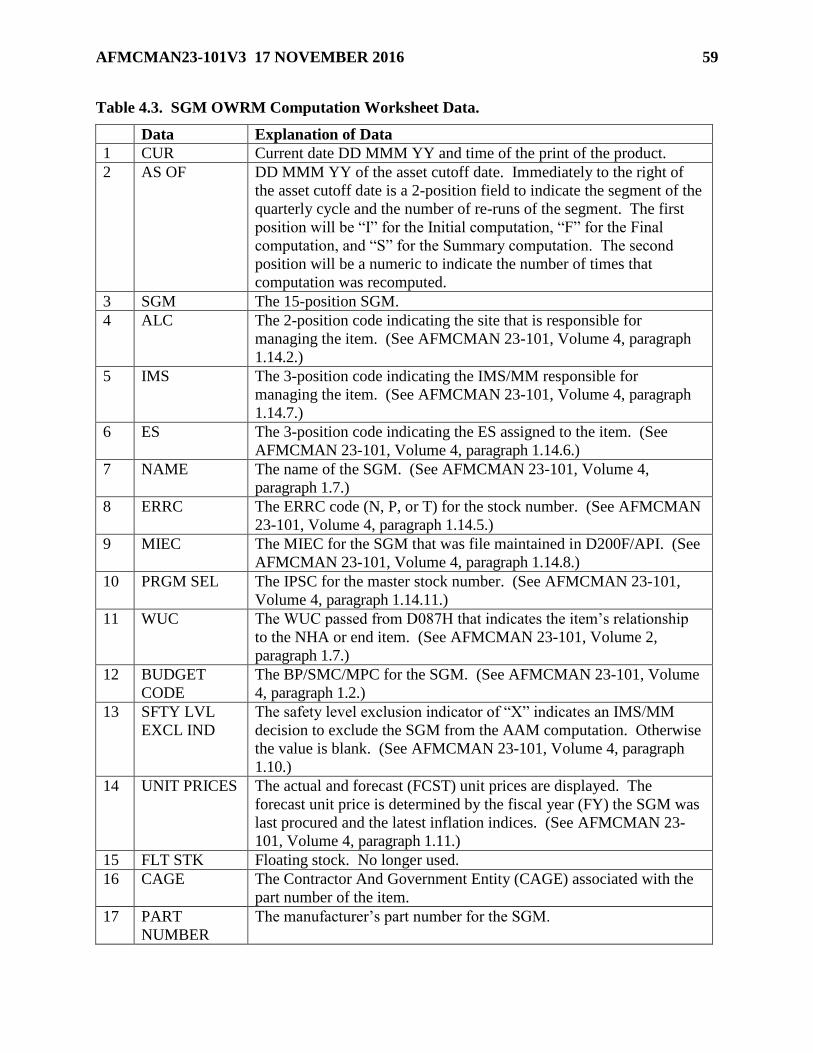
AFMCMAN23-101V3 17 NOVEMBER 2016 59
Table 4.3. SGM OWRM Computation Worksheet Data.
Data Explanation of Data
1 CUR Current date DD MMM YY and time of the print of the product.
2 AS OF DD MMM YY of the asset cutoff date. Immediately to the right of
the asset cutoff date is a 2-position field to indicate the segment of the
quarterly cycle and the number of re-runs of the segment. The first
position will be “I” for the Initial computation, “F” for the Final
computation, and “S” for the Summary computation. The second
position will be a numeric to indicate the number of times that
computation was recomputed.
3 SGM The 15-position SGM.
4 ALC The 2-position code indicating the site that is responsible for
managing the item. (See AFMCMAN 23-101, Volume 4, paragraph
1.14.2.)
5 IMS The 3-position code indicating the IMS/MM responsible for
managing the item. (See AFMCMAN 23-101, Volume 4, paragraph
1.14.7.)
6 ES The 3-position code indicating the ES assigned to the item. (See
AFMCMAN 23-101, Volume 4, paragraph 1.14.6.)
7 NAME The name of the SGM. (See AFMCMAN 23-101, Volume 4,
paragraph 1.7.)
8 ERRC The ERRC code (N, P, or T) for the stock number. (See AFMCMAN
23-101, Volume 4, paragraph 1.14.5.)
9 MIEC The MIEC for the SGM that was file maintained in D200F/API. (See
AFMCMAN 23-101, Volume 4, paragraph 1.14.8.)
10 PRGM SEL The IPSC for the master stock number. (See AFMCMAN 23-101,
Volume 4, paragraph 1.14.11.)
11 WUC The WUC passed from D087H that indicates the item’s relationship
to the NHA or end item. (See AFMCMAN 23-101, Volume 2,
paragraph 1.7.)
12 BUDGET
CODE
The BP/SMC/MPC for the SGM. (See AFMCMAN 23-101, Volume
4, paragraph 1.2.)
13 SFTY LVL
EXCL IND
The safety level exclusion indicator of “X” indicates an IMS/MM
decision to exclude the SGM from the AAM computation. Otherwise
the value is blank. (See AFMCMAN 23-101, Volume 4, paragraph
1.10.)
14 UNIT PRICES The actual and forecast (FCST) unit prices are displayed. The
forecast unit price is determined by the fiscal year (FY) the SGM was
last procured and the latest inflation indices. (See AFMCMAN 23-
101, Volume 4, paragraph 1.11.)
15 FLT STK Floating stock. No longer used.
16 CAGE The Contractor And Government Entity (CAGE) associated with the
part number of the item.
17 PART
NUMBER
The manufacturer’s part number for the SGM.

60 AFMCMAN23-101V3 17 NOVEMBER 2016
18 Rest of the
data
For descriptions of the rest of the data, see paragraphs 4.5., 4.6., 4.7.,
and 4.8.

AFMCMAN23-101V3 17 NOVEMBER 2016 61
Chapter 5
INSURANCE ITEMS AND NUMERIC STOCKAGE OBJECTIVE ITEMS
5.1. Introduction.
5.1.1. This chapter describes the guidance and procedures to be used by the IMS/MM and
ES for the management of non-demand-based items, also called INS and NSO items. These
are Air Force items that experience demand patterns that are incompatible with the demand-
based methodology of SIRS. The ES decides during the provisioning process (see AFMCI
23-106, Initial Requirements Determination) which items should be managed as demand
based or non-demand based (INS or NSO). Requirements for these items are computed by
SIRS using the computational method explained in paragraph 5.4. When FM is done, the
IMS/MMs must document their rationale using the Notepad.
5.1.2. Rates and percents are computed for all items, including INS and NSO. However,
INS items do not use usage in the calculation of their buy, repair, and retention levels. The
Usage Printout is no longer produced for INS and NSO items as a Factors/Usage Printout is
produced for all items. The results of the INS and NSO computation are displayed on the
Display INIS INS/NSO Item Status Listing screens and SIRS DIS CW INIS that is produced
from the Initial, Final, and Summary computation.
5.1.3. Stocks of INS and NSO items are normally maintained at depot level only. Under
specific circumstances, NSO items may be allowed to have minimum quantities at base level
based on various ASLs such as on items selected during initial provisioning. (See
AFMCMAN 23-101, Volume 4, paragraphs 4.4. and 4.6.1.)
5.1.4. The INS or NSO code is not assigned solely to retain assets. The use of these codes is
prohibited when the basic intent is to retain assets that might otherwise be in a computed long
supply or excess position.
5.1.5. The INS code is input from D043 to RIID to SIRS and has precedence over the other
values that could be input for the ICC (see AFMCMAN 23-101, Volume 4, paragraph 1.6.).
This will cause an “I” to be posted in the ICC on the SMCWs and the INS/NSO Item Status
Listing. Conversely, the only way to remove the “I” is to initiate a cataloging action in
D143C to pass to D043 to remove the code.
5.1.6. SIRS does not compute levels for INS and NSO items with a compute code of “B,”
“N,” “P,” “R,” and “X” (see AFMCMAN 23-101, Volume 4, paragraph 1.14.3.).
5.2. INS Items.
5.2.1. Retail stockage of INS items is not authorized; however, minimal quantities (normally
not more than two per depot) may be stored at the wholesale level.
5.2.2. Items identified as INS are stock listed in D043 with an AAC of “Z.” The IMS/MM
and ES will conduct a review of an INS item whenever a failure is reported. This review will
include an investigation of the mode of failure. Any item that experiences systematic usage
will be considered for a catalog change to remove the INS code if the Air Force is the PICA.
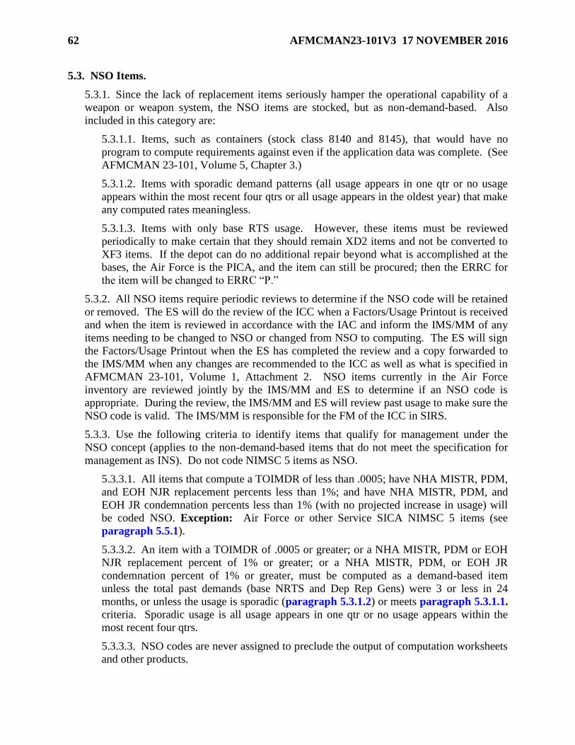
62 AFMCMAN23-101V3 17 NOVEMBER 2016
5.3. NSO Items.
5.3.1. Since the lack of replacement items seriously hamper the operational capability of a
weapon or weapon system, the NSO items are stocked, but as non-demand-based. Also
included in this category are:
5.3.1.1. Items, such as containers (stock class 8140 and 8145), that would have no
program to compute requirements against even if the application data was complete. (See
AFMCMAN 23-101, Volume 5, Chapter 3.)
5.3.1.2. Items with sporadic demand patterns (all usage appears in one qtr or no usage
appears within the most recent four qtrs or all usage appears in the oldest year) that make
any computed rates meaningless.
5.3.1.3. Items with only base RTS usage. However, these items must be reviewed
periodically to make certain that they should remain XD2 items and not be converted to
XF3 items. If the depot can do no additional repair beyond what is accomplished at the
bases, the Air Force is the PICA, and the item can still be procured; then the ERRC for
the item will be changed to ERRC “P.”
5.3.2. All NSO items require periodic reviews to determine if the NSO code will be retained
or removed. The ES will do the review of the ICC when a Factors/Usage Printout is received
and when the item is reviewed in accordance with the IAC and inform the IMS/MM of any
items needing to be changed to NSO or changed from NSO to computing. The ES will sign
the Factors/Usage Printout when the ES has completed the review and a copy forwarded to
the IMS/MM when any changes are recommended to the ICC as well as what is specified in
AFMCMAN 23-101, Volume 1, Attachment 2. NSO items currently in the Air Force
inventory are reviewed jointly by the IMS/MM and ES to determine if an NSO code is
appropriate. During the review, the IMS/MM and ES will review past usage to make sure the
NSO code is valid. The IMS/MM is responsible for the FM of the ICC in SIRS.
5.3.3. Use the following criteria to identify items that qualify for management under the
NSO concept (applies to the non-demand-based items that do not meet the specification for
management as INS). Do not code NIMSC 5 items as NSO.
5.3.3.1. All items that compute a TOIMDR of less than .0005; have NHA MISTR, PDM,
and EOH NJR replacement percents less than 1%; and have NHA MISTR, PDM, and
EOH JR condemnation percents less than 1% (with no projected increase in usage) will
be coded NSO. Exception: Air Force or other Service SICA NIMSC 5 items (see
paragraph 5.5.1).
5.3.3.2. An item with a TOIMDR of .0005 or greater; or a NHA MISTR, PDM or EOH
NJR replacement percent of 1% or greater; or a NHA MISTR, PDM, or EOH JR
condemnation percent of 1% or greater, must be computed as a demand-based item
unless the total past demands (base NRTS and Dep Rep Gens) were 3 or less in 24
months, or unless the usage is sporadic (paragraph 5.3.1.2) or meets paragraph 5.3.1.1.
criteria. Sporadic usage is all usage appears in one qtr or no usage appears within the
most recent four qtrs.
5.3.3.3. NSO codes are never assigned to preclude the output of computation worksheets
and other products.

AFMCMAN23-101V3 17 NOVEMBER 2016 63
5.3.3.4. Since D200A allows the file maintenance of the NSO code by individual current
stock number, it is possible to have some items within a two-way interchangeable group
to be coded NSO and the SGM to be coded as a computing item. When this occurs, the
message "not an INS/NSO item" will appear on the Insurance/NSO comp screen (CW
INIS, when in reality the item is coded as an NSO item. This is because the system has
rolled to the SGM which is coded as a computing item.
5.3.3.5. When an item’s demands for the past 8 qtrs are not reflective of its expected
future demands (i.e., a modification has removed an NSN from the weapon system), the
item must remain computing until the demands for the past 8 qtrs appropriately reflect
what is expected of future demands. Changing an item to NSO status before the high
usage ages out of the 8 qtrs will overstate future requirements.
5.4. Levels for INS and NSO Items.
5.4.1. SIRS will automatically calculate the INS/NSO levels. Adjustments to the levels
calculated by SIRS are attained by file maintaining adjustments to those areas affecting the
requirements lines used in the computation additives, adjusted levels, factors, etc. SIRS will
not allow the IMS/MM to increase the levels calculated by SIRS; however, the IMS/MM can
manually lower the INS/NSO levels calculated by SIRS by dropping the MIN DEP STK
LVL on the BMD screen to zero. SIRS will automatically calculate buy and repair levels for
the CY, AY, BY, and EY as well as the retention level.
5.4.2. If an NSO item has an AAC of “T” or “Y,” which means the item is obsolete, then
SIRS will automatically change the ICC to blank, and overlay all buy, repair, and retention
levels and quantities, with zeroes. In addition, if the obsolete item is a CSN that is part of a
SGM family which is NSO, the CSN’s ICC is set to blank, the levels are set to zero, and the
SRCs are set to “C.” The CSN’s data, including assets, is not used in the SGM’s
computation of the NSO levels.
5.4.3. If an INS item has an AAC of “T” or “Y,” the buy, repair, and retention levels and
quantities will be set equal to zero. SIRS cannot change the ICC from “I” to blank, as this is
a cataloging action.
5.4.4. SIRS will output the ICC for items coded INS or NSO on the IMS Review List and on
the ES Review List when the computed TOIMDR is greater than the NSO-TOIMDR-MIN
and/or when the computed DLM NJR replacement percent and/or JR condemnation percent
is greater than the NSO-NJR-REPL-PCT-MIN. The IMS/MM and ES will review the item.
The SIRS OPR will determine, establish, and file maintain the NSO-TOIMDR-MIN and the
NSO-NJR-PEPL-PCT-MIN on the Standard Data Table. (See AFMCMAN 23-101, Volume
2, paragraph 3.23.)
5.5. Special Rules for Items Managed by Multiple Services.
5.5.1. Items cataloged with a NIMSC 5, whether the Air Force is NIMSC 5 or the other
Service is NIMSC 5, are not coded NSO. SIRS will automatically change the ICC of “S” or
“Z” for NIMSC 5 items to blank for “computing” items. This allows a RDE transaction to be
received by the Air Force when it is the PICA or to be generated to the other Service when
the other Service is the PICA.

64 AFMCMAN23-101V3 17 NOVEMBER 2016
5.5.2. When an Air Force SICA NIMSC 5 item has been cataloged as an INS item due to the
use by the PICA of “Z” for the AAC, SIRS will output a notice to the IMS/MM and ES
saying “NIMSC 5 AND ITEM CATEGORY CODE ‘I’ ARE INCOMPATIBLE.” The
IMS/MM can change the ICC to blank only if the ICC is an “S” or “I” (see AFMCMAN 23-
101, Volume 4, paragraph 1.6.). By changing the Air Force SICA NIMSC 5 INS item to
computing within SIRS, the RDE will automatically be passed to the PICA. This item must
have a PICA/SICA Management Level Change and/or Reassignment Request on file
requesting that the PICA change the AAC (reference DoDM 4140.68).
5.6. INS/NSO Item Status Listing.
5.6.1. SIRS uses the methods included in the INS/NSO Item Status Listing to compute
requirements to determine the buy, termination, excess, and repair quantities. The ICC is set
to “I” or “S” when an INS or NSO item is established in SIRS. When either one of these
codes are removed through either a cataloging action or by IMS/MM FM in SIRS, the
computation of requirements will automatically be done using the normal computation
methods described in Chapter 1.
5.6.2. The INS/NSO Item Status Listing, AD200.ANBA#82B is the computation worksheet
that provides computational results for items that have an ICC of “I” for INS or “S” for NSO.
The computation worksheet provides a limited set of computational lines to display the buy
and repair quantities for the CY, AY, BY, and EY pick-off points. The hardcopy INS/NSO
Item Status Listing is automatically generated after each SIRS Initial and Summary
computation for items computing a buy, termination, repair, or excess, based on the IAC.
Printed products for the Final cycle are suppressed. For items computing excess, this product
is produced only if this is the first time the item is in excess, or if the current computed
excess quantity is larger than last cycle’s excess quantity. This listing also provides a
summary of the buy, termination, excess, and repair quantities and dollars. Each data
element displayed is described in paragraph 5.7 and 5.8 All this same data can be viewed
online using the Display INIS INS/NSO Item Status Listing screen, SIRS DIS CW INIS.
Historical data can be viewed online, by entering a valid AS OF date. There can be four or
more screens: summary of the buy, termination, repair, excess quantities (page 1), repair
detail (page 2), buy/retention detail (page 3), and the I&S family (page 4). Both the Repair
and Buy/Retention Detail page can take more than one screen to display all data. Type the
SGM in the SGM field, then after page 1 displays; use the paging commands to transfer to
the other pages.
5.7. Data Elements of Display INIS INS/NSO Item Status Listing Screen (Page 1). The AS
OF date identifies the quarterly date of the computation cycle in the format dd mmm yy. A 2-
position cycle indicator is displayed to the right of the AS OF field. The first position identifies
the computation cycle (“I” for initial, “F” for Final, and “S” for Summary). The second position
represents the number of times that item was recomputed during that computation cycle. A zero
means the item was not re-computed. Table 5.1 provides the data elements displayed across the
top of the page:
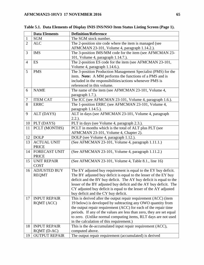
AFMCMAN23-101V3 17 NOVEMBER 2016 65
Table 5.1. Data Elements of Display INIS INS/NSO Item Status Listing Screen (Page 1).
Data Elements Definition/Reference
1 SGM The SGM stock number.
2 ALC The 2-position site code where the item is managed (see
AFMCMAN 23-101, Volume 4, paragraph 1.14.2.).
3 IMS The 3-position IMS/MM code for the item (see AFMCMAN 23-
101, Volume 4, paragraph 1.14.7.).
4 ES The 2-position ES code for the item (see AFMCMAN 23-101,
Volume 4, paragraph 1.14.6.).
5 PMS The 3-position Production Management Specialist (PMS) for the
item. Note: A MM performs the functions of a PMS and is
included in the responsibilities/actions whenever PMS is
referenced in this volume.
6 NAME The name of the item (see AFMCMAN 23-101, Volume 4,
paragraph 1.7.).
7 ITEM CAT The ICC (see AFMCMAN 23-101, Volume 4, paragraph 1.6.).
8 ERRC The 1-position ERRC (see AFMCMAN 23-101, Volume 4,
paragraph 1.14.5.).
9 ALT (DAYS) ALT in days (see AFMCMAN 23-101, Volume 4, paragraph
2.2.).
10 PLT (DAYS) PLT in days (see Volume 4, paragraph 2.3.).
11 PCLT (MONTHS) PCLT in months which is the total of ALT plus PLT (see
AFMCMAN 23-101, Volume 4, Chapter 2).
12 DOLP DOLP (see Volume 4, paragraph 1.12.).
13 ACTUAL UNIT
PRICE
(See AFMCMAN 23-101, Volume 4, paragraph 1.11.1.)
14 FORECAST UNIT
PRICE
(See AFMCMAN 23-101, Volume 4, paragraph 1.11.2.)
15 UNIT REPAIR
COST
(See AFMCMAN 23-101, Volume 4, Table 8.1., line 16)
16 ADJUSTED BUY
REQMT
The EY adjusted buy requirement is equal to the EY buy deficit.
The BY adjusted buy deficit is equal to the lesser of the EY buy
deficit and the BY buy deficit. The AY buy deficit is equal to the
lesser of the BY adjusted buy deficit and the AY buy deficit. The
CY adjusted buy deficit is equal to the lesser of the AY adjusted
buy deficit and the CY buy deficit.
17 INPUT REPAIR
RQMT (ACC)
This is derived after the output repair requirement (ACC) (item
19 below) is developed by subtracting any OWO quantity from
the output repair requirement (ACC) for each of the repair time
periods. If any of the values are less than zero, they are set equal
to zero. (Unlike normal computing items, RLT days are not used
in the calculation of this requirement.)
18 INPUT REPAIR
RQMT (D-AC)
This is the de-accumulated input repair requirement (ACC),
computed above.
19 OUTPUT REPAIR The output repair requirement (accumulated) is derived

66 AFMCMAN23-101V3 17 NOVEMBER 2016
RQMT (ACC) beginning with the CY repair period as the lesser of the gross
repair requirement and the assets available from repair. The AY,
BY, and EY values are then developed one at a time and
compared to the previous time period value. If the computed
value is less than the previous time period’s value, it is set equal
to the previous time period’s value. (The rationale is that it is not
possible to “un-repair” an asset.)
20 OUTPUT REPAIR
RQMT (D-AC)
This is the de-accumulated output repair requirement (ACC),
computed above.
21 TERMINATION The termination quantity is developed if there are on-order assets
and the serviceable assets and assets available from repair,
computed above, are greater than the computed termination level.
The term quantity is that difference.
22 EXCESS If the sum of the serviceable assets and assets available from
repair, computed above, is greater than the retention period level,
the excess quantity is equal to that difference.
5.8. Data Elements of Display INS/NSO Item Status Listing (Repair Detail) and
(Buy/Retention Detail), (Pages 2 and 3, First Screen). The below data elements (Table 5.2)
are displayed for repair for the CY, AY, BY, and EY, and for buy for the CY, AY, BY, and EY
with a final column for retention.

AFMCMAN23-101V3 17 NOVEMBER 2016 67
Table 5.2. Data Elements of Display INS/NSO Item Status Listing (Repair Detail) and
(Buy/Retention Detail) (Pages 2 and 3, First Screen).
Data Elements Definition
1 AF RECURRING
REQUIREMENT
This is equal to (usage times months) divided by the base
period.
1a Usage The sum of the past eight qtrs base NRTS, base
condemnations, and depot reparable generations. (If the base
RTS exclusion indicator is on, base RTS and base
condemnations will not be used.)
1b Months Represents the number of months in the given forecast period.
When computing the repair requirements, this is the number of
months from the AS OF date to the end of the CY, AY, BY,
and EY. When computing the buy requirements, this is PCLT
months plus the number of months from the AS OF date to the
end of the CY, AY, BY, and EY.
1c Base Period The number of months between the oldest application PBD and
the AS OF (asset cutoff date), up to a maximum of 24 months.
1d Termination Period
Value
The termination period value is equal to the BY buy value. For
INS items, these fields are set equal to zero. The number of
months in the retention period for SIRS is a variable
established by the AFMC SIRS OPR (AFSC/LGPS) and the
usage data is adjusted by a series of risk factors established at
weapon system level.
2 RDE RECURRING
REQUIREMENT
This is equal to the accumulated RDE recurring requirement
for each of the time periods. If the PCLT is not evenly
divisible by 3, the value will be prorated. The termination
period value is equal to the BY buy value. The retention period
value is the accumulated RDE recurring requirement through
the end of the 38 qtr time span.
3 NON-RECURRING
REQUIREMENT
This is equal to 1 plus the total additive requirements (which
includes DOTM (see AFMCMAN 23-101, Volume 4,
paragraph 5.5.1.), RSP W-B requirement from D087H (see
AFMCMAN 23-101, Volume 4, paragraph 5.4.1.), and total
ASL (see AFMCMAN 23-101, Volume 4, Chapter 4) at each
of the time periods. The termination period value is the greater
of the AY buy value or the BY buy value. The retention period
value is developed by adding 1 to the sum of the maximum
value for each of the total additive requirements, W-B
requirement, and total adjusted level.
4 XX YYY ZZZZ
REQUIREMENT
This is the I&S deficit (also called the 3rd short) passed up
from the lesser preferred SGM for each of the time periods.
The lesser preferred SGM may be another INS/NSO item or a
normal computing item. The “XX YYY ZZZZ” is the NIIN of
the lesser preferred SGM in the I&S family that passed the
deficit. If the item is a bachelor item, then the NIIN of the

68 AFMCMAN23-101V3 17 NOVEMBER 2016
bachelor item will display here. The termination period value
is equal to the BY buy value.
5 REPAIR LEVEL This is the sum of the Air Force recurring requirement, RDE
recurring requirement, non-recurring requirement, and I&S
requirement for each of the time periods. If the SGM is a
terminal item where the AAC is equal to “V,” then the buy
levels are set equal to zero. If the SGM is obsolete, (the AAC
is equal to “T” or “Y”), then all levels are set equal to zero.
6 SERVICEABLE
ASSETS
This is equal to the sum of serviceable on hand, serviceable on
order, and serviceable due-in assets available at each of the
time periods. All on-order and due-in assets, scheduled to be
delivered after the AY buy period, are brought back to the AY
buy period.
7 GROSS REPAIR
REQUIREMENT
This is equal to the level minus the serviceable assets (Table
5.2.). (Note: On the repair detail screen (page 2), the values
are the gross repair requirement for each time period (CY, AY,
BY, and EY). On the buy/retention detail screen (page 3), the
values are the gross buy requirement for each time period (CY,
AY, BY, and EY) with a fifth column for the gross retention
requirement. On the printed version, the first four values are
the gross repair requirement for each time period (CY, AY,
BY, and EY). The next four values are the gross buy
requirement for each time period (CY, AY, BY, and EY). The
last value is the gross retention requirement. There are no CY
values developed during the 30 September and 31 December
cycles.)
8 UNSERVICEABLE
ASSETS
This is the sum of the unserviceable on-hand assets and the
unserviceable TOC due-in assets available at each time period.
9 AF REPARABLE
GENERATIONS
For INS items, these fields are set equal to zero. For NSO
items, this is computed in the same manner as the Air Force
recurring requirement defined above, except that the value for
usage has the number of JR condemnations over the past eight
qtrs removed since no reparable asset will be turned into
supply. (Note: This is set to zero for all ERRC “N” and “P”
items.)
10 RDE REPARABLE
GENERATIONS
This is equal to the accumulated RDE reparable returns for
each of the time periods. If the PCLT is not evenly divisible by
3, the value will be prorated. The termination period value is
equal to the BY buy value. The retention period value is the
accumulated RDE reparable returns though the end of the 38
qtr time span.
11 TOTAL
UNSERVICEABLE
ASSETS
This is the sum of the unserviceable assets, Air Force reparable
returns, and RDE reparable generations computed above for
each time period.

AFMCMAN23-101V3 17 NOVEMBER 2016 69
5.9. Data Elements of INS/NSO Item Status Listing (Repair Detail) and (Buy/Retention
Detail) (Pages 2 and 3, Second Screen). The below data elements (Table 5.3) are displayed for
repair for the CY, AY, BY, and EY, and for buy for the CY, AY, BY, and EY with a final
column for retention.
Table 5.3. Data Elements of INS/NSO Item Status Listing (Repair Detail) and
(Buy/Retention Detail) (Pages 2 and 3, Second Screen).
Data Elements Definition
1 ANTICIPATED
CONDEMNATIONS
This is derived by multiplying the computed 8 qtr MISTR
condemnation percent times each of the unserviceable assets,
Air Force reparable returns, and RDE reparable generation
values separately, then rounding each of results before adding
them together. (This method is consistent with the way
condemnations are developed for computing items.)
2 NET
UNSERVICEABLE
ASSETS
This is derived by subtracting the anticipated condemnations
from the total unserviceable assets for each of the time periods.
3 TOC ASSETS The on-hand TOC assets. The same value is displayed in each
of the time periods.
4 ASSETS AVAIL
FROM REPAIR
These are the net unserviceable assets added to the TOC assets
computed above for each time period.
5 DEFICIT POSITION This is derived by subtracting the assets available from repair
from the gross repair requirements computed above for each
time period. If the result is less than zero, it is set equal to
zero.
5.10. Display INIS INS/NSO Item Status Listing (I&S Family Members) (Page 4). This
screen displays the entire I&S family, including the order of use code. The middle digit of the
order of use code designates the subgroup. The highest middle digit is the most preferred. The
highest middle digit and third digit combination is the I&S family master. Additional members
of a subgroup are offset under the SGM. It is possible to change the order of use using the I&S
structure FM screen (see AFMCMAN 23-101, Volume 4, paragraph 1.15.).
5.11. INIS INS/NSO Item Status Listing Report. In addition to the data elements listed in the
previous paragraphs, the below summary data elements (Table 5.4) appear on the hardcopy
version of the INS/NSN Item Status Listing.

70 AFMCMAN23-101V3 17 NOVEMBER 2016
Table 5.4. Summary Data Elements of INIS INS/NSO Item Status Listing Report.
Data Elements Definition
1 BUY
QUANTITY/DOLLAR
VALUE
The buy quantity is equal to the AY adjusted buy quantity;
Exception: For March cycle, it equals the CY adjusted buy
quantity. The buy dollar value is equal to the buy quantity times
the forecast unit price.
1a Similar to R coded retention, rationale for retaining the item in
the stock list without buying must be approved through your
Supply Chain Management Group commander or equivalent and
coordinated with your local D200A Functional OPR. A
consolidated set of rationale for the site (list each basic rationale
and number of items in each group using that rationale) will be
provided annually to AFSC/LGPS by the local D200A Functional
OPR.
1b Items retained in the stock list without buying will be assigned
deferred disposal code “M.” This will prevent them from
computing buys in D200 and the Automated Budget Compilation
System (ABCS).
2 TERMINATION
QUANTITY/DOLLAR
VALUE
The termination quantity is developed if there are on-order assets
and the serviceable assets and assets available from repair
computed above are greater than the computed termination level.
The term quantity is that difference. The term dollar value is
equal to the term quantity times the actual unit price.
3 EXCESS
QUANTITY/DOLLAR
VALUE
If the sum of the serviceable assets and assets available from
repair computed above is greater than the retention period level,
the excess quantity is equal to that difference. The excess dollar
value is equal to the excess quantity times the actual unit price.
4 REPAIR
QUANTITY/DOLLAR
VALUE
The repair quantity is equal to the input repair requirement (ACC)
for the AY repair period. The repair dollar value is equal to the
repair quantity times the weighted unit repair cost.

AFMCMAN23-101V3 17 NOVEMBER 2016 71
Chapter 6
INDEX OF ACTIONS PRODUCTS
6.1. Introduction. Secondary Item Requirements System (SIRS) produces 15 Index of Actions
(IOAs) reports. The IOAs products list, by SGM stock number, items which should be
considered for acquisition, termination/PR reduction, disposal, repair negotiations, rescheduling
of on-order assets, or expediting deliveries of on-order quantities. Displayed on the hard copy,
is the 2-position cycle indicator, after the “as of” date. The first position is an “I,” “F,” or “S” to
identify the computation cycle (Initial, Final or Summary). The second field is a number
representing the number of times that item has been recomputed, with 0 meaning the item has
not been re-computed.
6.2. The Buy, Termination and Excess IOA Products. Table 6.1 lists the nine buy,
termination, and excess IOA reports.
Table 6.1. Buy, Termination and Excess IOA Products.
IOA Report Report Description Report Number
1 Net Buy by
NSN
Provides the computed buy quantities and
dollars by NSN.
AD200.AF0A#8A4
2 Net Buy by
MMAC/FSC
Provides the computed buy quantities and
dollars by Materiel Management
Aggregation Code (MMAC) and Federal
Stock Classification (FSC).
(AD200.AE8A#8A4)
3 Net Buy by
BP/SMC
Provides the computed buy quantities and
dollars by BP and SMC.
(AD200.AFWA#8A4)
4 Termination
by NSN
Provides the computed termination
quantities and dollars by NSN.
(AD200.AF1A#8A4)
5 Termination
by
MMAC/FSC
Provides the computed termination and
dollars by MMAC and FSC.
(AD200.AFXA#8A4)
6 Termination
by BP/SMC
Provides the computed termination and
dollars by BP/SMC.
(AD200.AFYA#8A4)
7 Excess by
NSN
Provides the computed excess quantities
and dollars by NSN.
(AD200.AF2A#8A4)
8 Excess by
MMAC/FSC
Provides the computed excess quantities
and dollars by MMAC/FSC.
(AD200.AG1A#8A4)
9 Excess by
BP/SMC
Provides the computed excess quantities
and dollars by BP/SMC.
(AD200.AGYA#8A4)
6.3. The Repair IOA Products. Table 6.2 lists the six repair IOA reports.

72 AFMCMAN23-101V3 17 NOVEMBER 2016
Table 6.2. Repair IOA Reports.
IOA Report Report Description Report Number
1 Repair by
MMAC/FSC
by AY
Provides the computed repair input
quantities and dollars by MMAC/FSC for
the AY.
(D200.AJHA#87I)
2 Repair by
BP/SMC by
AY
Provides the computed repair input
quantities and dollars by BP/SMC for the
AY.
(AD200.AJIA87I)
3 Repair by IMS
by AY
Provides the computed repair input
quantities and dollars by IMS code by
AY.
(AD200.AJKA#87I)
4 Repair by
Division by
AY
Provides the computed repair input
quantities and dollars by division code by
AY.
(AD200.AJLA#87I)
5 Repair by ES
by AY
Provides the computed repair input
quantities and dollars by ES code by AY.
(AD200.AJMA#87I)
6 Repair by
Division by
SGM
Provides the computed repair input
quantities and dollars by division code by
SGM.
(AD200.AJNA#87I)
6.4. Format for the Net Buy, Termination, and Excess IOA Reports (Table 6 3.). The top
line displays the site. On some reports the MMAC and FSC or the BP and SMC are identified.

AFMCMAN23-101V3 17 NOVEMBER 2016 73
Table 6.3. Data Common to IOA Reports for Net Buy, Termination and Excess Reports.
Report Data Data Explanation
1 NSN SGM This entry represents the I&S SGM/bachelor stock number that has
been computed. These stock numbers are sequenced in descending
order based upon the highest to lowest extended dollar value of the
product.
2 BP This is the 2-digit BP that is a part of the 10-digit budget code
assigned to the item. (See AFMCMAN 23-101, Volume 4,
paragraph 1.2.1.)
3 SMC This is the 4-digit SMC that is a part of the 10-digit budget code
assigned to the item. (See AFMCMAN 23-101, Volume 4,
paragraph 1.2.3.)
4 IMS The 3-digit IMS code.
5 ES The 3-digit ES code.
6 PMS The 3-digit PMS code.
7 ITM DFR CDE Item Deferred Disposal Code. (See AFMCMAN 23-101, Volume
4, paragraph 1.3.1.)
8 ITM CTG CDE The ICC can be an “I” (INS), “S” (NSO), blank (active item), or
“L,” “Y” or “Z” (LOTB) item. (See AFMCMAN 23-101, Volume
4, paragraph 1.6.)
9 AMC The AMC and suffix code as received from the RIID system
(D200E). It identifies the extent of screening and internal
management procedures for determining future procurement
processing.
10 ERRC Code The 1-position ERRC code applicable to the I&S SGM/bachelor
stock number. The code can be “T,” “N,” or “P.” (See
AFMCMAN 23-101, Volume 4, paragraph 1.14.5.)
11 U-P FCST The FUP is the result of multiplying the unit price by the
appropriate inflation factor as determined by the DOLP. (See
AFMCMAN 23-101, Volume 4, paragraph 1.11.2.)
12 U-P Comp The actual unit price. (See AFMCMAN 23-101, Volume 4,
paragraph 1.11.1.)
13 Value Sub
Total
If displayed, this is the total dollar value of all of the items listed,
for the category displayed at the top of the page.
14 Items Sub
Total
If displayed, this is the total number of items, for the category
displayed at the top of the page.
15 Value Grand
Total
The total dollar value of all of the items listed on the applicable IOA
product.
16 Items Grand
Total
The total number of items listed on the applicable IOA product.
6.4.1. IOA products for net buy (Table 6.4) lists the buy quantity and buy dollars in the last
two columns.

74 AFMCMAN23-101V3 17 NOVEMBER 2016
Table 6.4. Data Specific to IOA Reports for Net Buy.
Report Data Data Explanation
1 Buy Qty The total net buy requirement that has been computed in the
computation. The quantity is that figure which is displayed on the
3rd short position at the buy period column and also on the results
page of the SMCW. When an * is displayed, the buy quantity is less
than or equal to 5% of the worldwide buy operating level.
2 Buy Dollars The extended value in dollars and cents of the net buy quantity,
obtained by multiplying the quantity by the forecast unit price. This
is the dollar value by which the buy item indices are sequenced.
Buy items are listed in descending order starting with the highest net
buy value.
6.4.2. IOA products for net terminations (Table 6.5) lists the termination quantity and
termination dollars in the last two columns.
Table 6.5. Data Specific to IOA Reports for Net Terminations.
Report Data Data Explanation
1 Term Qty The total on-order quantity (sum of on-order PR funded and on-order
contract) which is excess to the worldwide termination level. The
excess on-order quantity is determined by comparing worldwide
assets, including the on-order quantities, to the worldwide termination
level developed in the requirements computation. The termination
quantity developed this way could be different than that which is
shown on the 3rd over position at the termination period column of the
requirements computation worksheet. The termination quantity, to be
considered for action, is that which is shown on the results page of the
requirements computation worksheet.
2 Term Dollars The extended value in dollars and cents of the contract termination
quantity, obtained by multiplying the quantity by the unit price. This
is the dollar value by which the termination item indices are
sequenced. Termination items are listed in descending order, starting
with the highest contract termination value.
6.4.3. The IOA products for net excess (Table 6.6) will list the excess quantity and excess
dollars in the last two columns.

AFMCMAN23-101V3 17 NOVEMBER 2016 75
Table 6.6. Data Specific to IOA Reports for Net Excess.
Report Data Data Explanation
1 Excess Qty The total excess quantity of assets (sum of serviceable, unserviceable,
TOC, and due-in assets), which are excess to the worldwide select
retention level. The excess quantity is determined by comparing the
total non-obsolete assets to the worldwide select retention level. Added
to that excess quantity are the obsolete assets reported for the I&S
SGM/bachelor stock number. Items that carry a deferred disposal code
will have their excess quantities included. The excess quantity to be
considered for action is that which is shown on the results page of the
requirements computation worksheet.
2 Excess
Dollars
The extended value in dollars and cents of the excess quantity is
obtained by multiplying the quantity by the actual unit price. This is the
dollar value by which the excess item indices are sequenced. Excess
items are listed in descending order starting with the highest excess
value.
6.5. Format of the Repair IOAs Reports (Table 6 7.). The item will be displayed only if it
computes a repair requirement in the AY.
Table 6.7. Data Specific to IOAs Reports for Repair.
Report Data Data Explanation
1 NSN SGM This entry represents the I&S SGM/bachelor stock number that has been
computed. These stock numbers are sequenced in descending order
based upon the highest to lowest extended dollar value of repair in the
AY. This applies to all the indices; Exception: D200.AJNA#87I
(Division, Master Stock Number) which is in stock number sequence.
2 Unit Repair
Man-Hr
The unit repair man-hours are the maintenance standard direct product
hours that it will take to repair the stock number.
3 Unit Rpr
Cost/FCST
Unit Price
The unit weighted repair cost computed by SIRS. (See AFMCMAN
23-101, Volume 4, Table 8.1, Line 10) The FUP computed by SIRS.
(See AFMCMAN 23-101, Volume 4, paragraph 1.11.2.)
4 FY The first FY column represents the AY in the requirements
computation, also called the operating year. It will represent 4 qtrs for
the 30 June and 30 September cycles, 3 qtrs for the 31 December cycle,
and 2 qtrs for the 31 March cycle. The second column is the BY. The
third column is the EY.
5 Input Qty Represents the net MISTR input quantity computed for the AY. The net
MISTR input combines the peacetime, WRSK/BLSS, and OWRM
quantities.
6 Dollar Value The dollar value is determined by the repair cost times the input
quantity developed for this FY. This is the dollar value by which the
repair item indices are sequenced. Repair items are listed in descending
order starting with the highest repair value.
7 Total Man-Hr The total man-hours are determined by multiplying the unit repair man-
hours times the input quantity developed for the AY.

76 AFMCMAN23-101V3 17 NOVEMBER 2016
8 MIEC The 3-position MIEC defines how essential the item is to the wartime
mission of the weapon system. (See AFMCMAN 23-101, Volume 5,
paragraph 3.27.)
9 Itm Cat The ICC can be an “I” (INS), “S” (NSO), or blank (active item), or “L,”
“Y” or “Z” (LOTB) item. (See AFMCMAN 23-101, Volume 4,
paragraph 1.6.)
10 ICS RIW The ICS/RIW code is a “C” to identify ICS items and a “W” to identify
RIW items. (See AFMCMAN 23-101, Volume 4, paragraph 1.4.)
11 ICS RIW Exp
Dt
This is the expiration date (YYMM) of the ICS or RIW code. (See
Volume 4, paragraph 1.4.)
12 SOR/PCT Five SOR percentages can be displayed. (See AFMCMAN 23-101,
Volume 4, Table 8.1, Line 11)
13 Sub Total
Items
The sub-total items (master stock numbers) are printed under each
applicable FY column.
14 Sub Total
Units
The sub-total units (net MISTR input quantity) are printed under each
applicable FY column.
15 Sub Total M-
Hrs
The sub-total man-hours are printed under each applicable FY column.
16 Sub Total
Value
The sub-total dollar value (input quantity times unit repair cost) for all
items with extended dollar values are printed under each applicable FY
column.
17 Grand Total
Items
The total items (master stock numbers) are printed under each
applicable FY column.
18 Grand Total
Units
The total units (net MISTR input quantity) are printed under each
applicable FY column.
19 Grand Total
M-Hrs
The total man-hours are printed under each applicable FY column.
20 Grand Total
Value
The total dollar value (input quantity times unit repair cost) for all items
with extended dollar values are printed under each applicable FY
column.
6.6. Display IOAs Screens.
6.6.1. These products are displayed online. From the Display SIRS menu, select INDX,
which will bring up the only screen, the Display IOA Index of Actions Selection Screen,
SIRS DIS INDX. Only one type of index and one sort criteria can be selected at a time.
Some sort criteria are marked as “repair only” meaning that selection is only valid for the
repair IOA data.
6.6.2. Additional data can be viewed by using the scrolling commands (FORW, BACK).
(Note: “GUI” forward, back, top, and bottom buttons are currently not available. Use
FORW, BACK, TOP, or BOTT at the command line to scroll through data.) Only current
cycle data can be viewed. After the AS OF date is an “I,” “F,” or “S” to identify the
computation cycle (Initial, Final or Summary). The second field is a number representing the
number of times that item has been recomputed, with 0 meaning the item has not been re-
computed.
AFMCMAN23-101V3 17 NOVEMBER 2016 77
6.6.3. For explanations of the data elements displayed on the Display IOA Index of Actions
Net Buy screen, see Table 6.3, 6.4., 6.5. and 6.6. The buy screen displays SGMs in
descending dollar value based on the computed dollar value of the buy quantity. The
termination screen displays SGMs in descending dollar value based on the computed dollar
value of the termination quantity. The excess screen displays SGMs in descending dollar
value based on the computed dollar value of the excess quantity. If there are two equal dollar
values then the data is displayed in ascending SGM order. Grand total value is the total
dollar value. Grand total items is the total number of SGMs.
6.6.4. There are two screens for the Display IOA Index of Actions Repair screens. Use the
Right/Left buttons (or mainframe paging commands (RIGH, LEFT) to view both screens and
the scrolling commands to view additional data. (Note: “GUI” right and left buttons are
currently not available. Use RIGH or LEFT at the command line to view additional data.)
The first (left) screen displays SGMs in descending dollar value based on the computed
dollar value of the repair quantity for the AY. If there are two equal dollar values, the data is
displayed in ascending SGM order. If the user selected site, DIV, and NSN sequence, then
the report is displayed sorted by SGM only, not dollar value. After the AY data, the BY and
EY data is displayed for each item. The following four totals are displayed in three columns
for each FY (AY, BY, and EY). Total items is the total number of SGMS. Total units is the
number of units. Total M-Hrs is the total number of man-hours. Total value is the total
dollar value. The second (right) screen displays additional data. See Table 6.7 for
explanations of the data elements displayed on both repair screens.
DONALD E. KIRKLAND
Brigadier General, USAF
Director, Logistics, Civil Engineering and Force
Protection

78 AFMCMAN23-101V3 17 NOVEMBER 2016
Attachment 1
GLOSSARY OF REFERENCES AND SUPPORTING INFORMATION
References
DoD 4100.39-M, Federal Logistics Information System (FLIS) Procedures Manual, Volume 10,
Multiple Application References/Instructions/Tables and Grids, October 2010
DoDM 4140.68, Integrated Materiel Management of Nonconsumable Items, 2 September 2014
AFH 23-123, Volume 1, Materiel Management Reference Information, 8 August 2013
AFH 23-123, Volume 2, Part 2, Integrated Logistics System-Supply (ILS-S), Standard Base
Supply System Operations, 8 August 2013AFI 23-101, Air Force Materiel Management, 29
January 2016
AFI 25-101, War Reserve Materiel (WRM) Program Guidance and Procedures, 2 May 2005
AFMAN 21-106, Joint Regulation Governing the Use and Application of Uniform Source
Maintenance, and Recoverability Codes, 29 August 2014
AFMCI 23-106, Initial Requirements Determination, 3 February 1997
AFMCI 23-112, Management of Items Subject to Repair (MISTR), 7 March 2006
AFMCI 23-205, Planning for DLA-Managed Consumables (PDMC), 26 April 2012
AFMCMAN 20-2, Security Assistance Program (SAP) Logistics Procedures, 16 January 2014
AFMCMAN 23-101, Volume 1, General D200A/N Information, TBD
AFMCMAN 23-101, Volume 2, System Level Data and OPR Reports (D200A, D200N), TBD
AFMCMAN 23-101, Volume 4, IMS/PMS/MM Data and Reports (D200A, D200N), TBD
AFMCMAN 23-101, Volume 5, Equipment Specialist Data and Reports (D200A, D200N), TBD
AFMCMAN 23-3, Cataloging and Standardization, 14 September 2010
T.O. 00-20-3, Maintenance Processing of Reparable Property and the Repair Cycle Asset
Control System, 15 August 2015
T.O. 00-25-195-WA-1, AF Technical Order System Source, Maintenance, and Recoverability
Coding of Air Force Weapons, Systems, and Equipments, 29 October 2012
Adopted Forms
AFMC Form 206, Temporary Work Request
Acronyms
AAC—Acquisition Advice Code
AAM—Aircraft Availability Model
ABCS—Automated Budget Compilation System
AC and/or ACC—Accumulated
AFMC—Air Force Materiel Command

AFMCMAN23-101V3 17 NOVEMBER 2016 79
AFSC—Air Force Sustainment Center
ALC—Air Logistics Complex
ALT—Administrative Lead Time
AMC—Acquisition Method Code
API—Applications, Programs, Indentures
APSC—Application Program Select Code
ASL—Adjusted Stock Level
AY—Apportionment Year
BMD—Basic Management Data
BP—Budget Program
BY—Budget Year
CAD/PAD—Cartridge Actuated Device/Propellant Activated Device
CAGE—Contractor And Government Entity
CAV AF—Commercial Asset Visibility Air Force
CLIN—Contract Line Item Number
CSIS—Central Secondary Item Stratification
CSN—Current Stock Number
CY—Current Year
DAC—Deaccumulated
DLIS—Defense Logistics Information Service
DLM—Depot Level Maintenance
DMISA—Depot Maintenance Interservice Support Agreement
DOLP—Date of Last Procurement
DOTM—Due Out To Maintenance
EOH—Engine Overhaul
EOQ—Economic Order Quantity
ERRC—Expendability, Recoverability, Reparability, Category
ES—Equipment Specialist
EY—Extended Year
FAA—Federal Aviation Administration
FEEMS—Field Engine Exchangeable Management System
FM—File Maintenance
80 AFMCMAN23-101V3 17 NOVEMBER 2016
FMS—Foreign Military Sales
FSC—Federal Stock Class
FUP—Forecast Unit Price
FY—Fiscal Year
GFAE—Government Furnished Aerospace Equipment
GFM—Government Furnished Materiel
GFP—Government Furnished Property
GUI—Graphic User Interface
HPMSK—High Priority Mission Support Kit
I&S—Interchangeability and Substitutability
IAC—Item Activity Code
ICC—Item Category Code
ICS—Interim Contractor Support
IMS—Inventory Management Specialist
INS—Insurance
IOA—Index of Actions
IPSC—Item Program Select Code
ISSP—Interservice Supply Support Program
JCAP—Joint Conventional Ammunition Production
JR—Job Routed
LOTB—Life Of Type Buy
LRS—Logistics Readiness Squadron
LRU—Line Replacement Unit
MAH—Moving Average History
MM—Materiel Manager
MD—Mission Designator
MIEC—Mission Item Essentially Code
MIPR—Military Interdepartmental Purchase Request
MISTR—Management of Items Subject to Repair
MMAC—Materiel Management Aggregation Code
MPC—Materiel Program Code
NHA—Next Higher Assembly

AFMCMAN23-101V3 17 NOVEMBER 2016 81
NIIN—National Item Identification Number
NIMSC—Nonconsumable Item Materiel Support Code
NJR—Non Job Routed
NRTS—Not Reparable This Station
NSN—National Stock Number
NSO—Numeric Stockage Objective
O&ST—Order and Shipping Time
OIM—Organizational and Intermediate Maintenance
OC-ALC—Oklahoma Air Logistics Complex
OO-ALC—Ogden Air Logistics Complex
OPR—Office of Primary Responsibility
OWO—On Work Order
OWRM—Other War Reserve Materiel
PBD—Program Begin Date
PCLT—Procurement Lead Time
PD—Period
PDM—Programmed Depot Maintenance
PICA—Primary Inventory Control Activity
PLT—Production Lead Time
PMS—Production Management Specialist
POM—Program Objective Memorandum
POS—Peacetime Operating Stock
PR—Purchase Request
PRELOG—Predictive Logistics
QPA—Quantity Per Application
qtr—Quarter
RAMP—Reportable Asset Management Process
RDE—Requirements Data Exchange
REALM—Requirements Execution/Availability Logistics Module
RIID—Requirements Item Identification Data
RIRQ—Routed Item Repair Quantity
RIW—Reliability Improvement Warranty

82 AFMCMAN23-101V3 17 NOVEMBER 2016
RLT—Repair Lead Time
RIC—Routing Identifier Code
RRRQ—Routed Repair Replacement Quantity
RSP—Readiness Spares Package
RTS—Reparable This Station
SBSS—Standard Base Supply System
SGM—Subgroup Master
SICA—Secondary Inventory Control Activity
SIRS—Secondary Item Requirements System
SMC—System Management Code
SMCW—SGM Computation Worksheet
SOR—Source of Repair
SRAN—Stock Record Account Number
SRC—Source Reference Code
SRU—Shop Replacement Unit
TASK—Turn-Around Spares Kit
TOC—Technical Order Compliance
TOIMDR—Total Organizational and Intermediate Maintenance Demand Rate
W-B—War Readiness Spares Kits and Base Level Self-sufficiency Spares
WCDO—War Consumable Distribution Objective
WR-ALC—Warner-Robins Air Logistics Complex
WRM—War Reserve Materiel
WSMIS—Weapon System Management Information System
WUC—Work Unit Code
Terms
Acquisition— Obtaining logistics support, supplies, or services under an acquisition agreement
or under a cross-servicing agreement. This includes purchasing (whether for payment in
currency, replacement-in-kind, or by exchange for equal value), renting, leasing, or any method
of temporarily obtaining logistics support, supplies, or services. Reference DoDM 4140.01,
Volume 1, DoD Supply Chain Materiel Management Procedures: Operational Requirements.
Acquisition Advice Code (AAC)—Codes indicating how (as distinguished from where) and
under what restrictions an item will be acquired. Reference DoD 4100.39-M, Volume 10, Table
58.
AFMCMAN23-101V3 17 NOVEMBER 2016 83
Acquisition Method/Acquisition Method Suffix Code—A code reflecting the decision of the
Primary Inventory Control Activity (PICA) from a planned procurement review. A combination
of two codes is required. Reference DoD 4100.39-M, Volume 10, Table 71.
Activity— A unit, organization, or installation performing a function or mission, (e.g., reception
center, redistribution center, naval station, naval shipyard). Reference Joint Publication 1-02,
DoD Dictionary of Military Terms.
Additive Requirement— Requirements that are supported by projected requirements (e.g.,
modifications) rather than past demand experience. Requirements computed outside the
recoverable computation. Reference AFI 23-101.
Adjustments (Physical Inventory)— The accounting transaction that corrects a book balance to
agree with the quantity of the item in storage. Such adjustments may result from (1) physical
inventory, (2) a potential discrepancy revealed by a materiel release denial or location
survey/reconciliation, (3) capitalization/decapitalization actions, (4) reidentification of stock, (5)
type of pack changes, (6) catalog data changes, (7) supply condition and purpose code changes,
etc. Reference DLM 4000.25, Defense Logistics Management Standards.
Administrative Lead Time (ALT)— The time interval between initiation of a purchase request
and the date of signature of a contract. Reference DoDM 4140.01, Volume 2, DoD Supply
Chain Materiel Management Procedures: Demand and Supply Planning.
Applications, Programs, and Indentures (API)(D200F)—A subsystem of the Air Force
Requirements Management System (RMS) and is the approved Air Force tool for maintaining
hardware indentures and relating program data to secondary items. Reference AFMCI 23-109,
Applications, Programs and Indentures.
Apportionment Year (AY)— The second Fiscal Year (31 March and 30 June cycle) or first
Fiscal Year (30 September and 31 December). It is also known as the operating year.
Assembly— In logistics, an item forming a portion of equipment that can be provisioned and
replaced as an entity and which normally incorporates replaceable parts or groups of parts.
Reference DoDM 4140.01, Volume 2.
Automated Budget Compilation System (ABCS)—An online, real-time main frame system
that resides on the Logistics and Sustainment Management Data Bank (LMDB)(D075). It is
used to prepare budget submissions for both buy and repair of AFMC- managed reparables and
consumables. Reference AFMCI 23-112, Management of Items Subject to Repair (MISTR).
Budget— A planned program for a fiscal period in terms of estimated costs, obligations, and
expenditures. Reference AFMAN 65-604, Appropriation Symbols and Budget Codes.
Budget Code— A one-position alphanumeric code employed by the Air Force to identify
investment items to budget programs from which procurement of the particular items is funded,
or to identify expense items to the various divisions of the Air Force Stock Fund. Reference
DoD 4100.39-M, Volume 10, Table 67.
Budget Year (BY)— The fiscal year covered by the budget estimate. A budget year begins 1
October and ends 30 September of the following calendar year. It is used by the federal
government for accounting purposes, and is frequently referred to as "BY". Reference AFMAN
65-604

84 AFMCMAN23-101V3 17 NOVEMBER 2016
Cataloging— The process of uniformly identifying, describing, classifying, numbering, and
publishing in the Federal Catalog System all items of personal property (items of supply)
repetitively procured, stored, issued, or used by federal agencies. Reference DoDM 4140.01,
Volume 8, DoD Supply Chain Materiel Management Procedures: Materiel Data Management
and Exchange.
Central Secondary Item Stratification (CSIS)— An automated capability that applies to
wholesale and retail asset and requirements data. The CSIS shall uniformly display the materiel
requirements and associated asset status of individual secondary items and generate summaries
of essential information. If a methodology other than stratification is used as a foundation, an
audit trail to the applicable stratification table shall be submitted to the USD(L&MR). Secondary
item assets shall be stratified at least semiannually. One stratification shall be as of September 30
(for inventory reporting and funding reviews), and the other shall be as of March 31 (for budget
preparation). Reference AFI 23-101.
Commercial and Government Entity (CAGE) Code— A five character data element assigned
to establishments which are manufacturers or have design control of items of supply procured by
the Federal Government. Reference DoD 4100.39-M, Glossary.
Component— In logistics, a part or combination of parts having a specific function, which can
be installed or replaced only as an entity. Reference DoDM 4140.01, Volume 6, DoD Supply
Chain Materiel Management Procedures: Materiel Returns, Retention, and Disposition.
Computation Asset Cutoff Date—The last day of each calendar quarter (31 December, 31
March, 30 June, and 30 September). The Secondary Item Requirements System (SIRS)(D200A)
computes items using data that are current on these dates.
Compute Code—One-digit alpha code assigned to all subgroup master items in SIRS that tells
D200A to perform or not perform a computation. SIRS generates the compute code; it cannot be
file maintained.
Consumable Item— An item of supply or an individual item (except explosive ordnance and
major end items of equipment) that is normally expended or used up beyond recovery in the use
for which it is designed or intended. Reference DoDM 4140.01, Volume 2.
Contract— A mutually binding legal relationship obligating the seller to furnish the supplies or
services (including construction) and the buyer to pay for them. It includes all types of
commitments that obligate the Government to an expenditure of appropriated funds and that,
except as otherwise authorized, are in writing. In addition to bilateral instruments, contracts
include (but are not limited to) awards and notices of awards; job orders or task letters issued
under basic ordering agreements; letter contracts; orders, such as purchase orders, under which
the contract becomes effective by written acceptance or performance; and bilateral contract
modifications. Contracts do not include grants and cooperative agreements covered by 31
U.S.C. 6301, et seq. Reference FAR, Subpart 2.1.
Contract Line Item— An item of supply or service on a contractual document usually identified
by a contract line item number (CLIN). Reference DFARS 204.7103.
Contract Termination— The cessation or cancellation, in whole or in part, of work under a
prime contractor a subcontract for the convenience of, or at the option of, the government, or due

AFMCMAN23-101V3 17 NOVEMBER 2016 85
to failure of the contractor to perform in accordance with the terms of the contract. Reference
AFI 23-101.
Contractor—An authorized Air Force contractor that occupies the facilities of, or receives
support from, another Air Force, Air Force Reserve, or Air National Guard unit. Reference AFI
65-601, Volume 1.
Current Year (CY)— The first Fiscal Year covering the time period from the computation asset
cutoff date to the first day of the next FY (1 October).
Customer— The individual or activity requesting or ordering a material asset at any
organizational level. Reference DoDM 4140.01, Volume 5, DoD Supply Chain Materiel
Management Procedures: Delivery of Materiel.
Data Element— A basic unit of information in a business transaction. Reference DLM
4000.25.
Demand— An indication of a requirement, a requisition, or similar request for an item of supply
or individual item. Demands are categorized as either recurring or non-recurring. Reference
DoDM 4140.01, Volume 1.
Deferred Disposal Code (DDC)—A one-position alphabetic codes that indicates the reason for
deferring the disposal of an item.
Depot Maintenance Inter-Service Support Agreement (DMISA)— A formalized agreement
similar to a contract whereby one Service (the Agent) obligates itself to provide depot
maintenance support for another Service (the Principal). (Source: OPNAVINST 4790.14A, et.al)
For the purpose of this manual, DMISA also covers depot maintenance provided for under inter-
Service support agreements not covered by the referenced joint regulation. Reference DLM
4000.25.
Depot Repair Cycle (DRC)—Begins when a maintenance activity determines that an
unserviceable item can be repaired and end when the unserviceable item is restored to
serviceable condition and is recorded as such on supply records. Include all time between the
beginning and end of the repair cycle in computing repair-cycle requirements, except avoidable
time, such as time expended due to the lack of a repair requirement or inefficiency. Beginning
and ending points of each segment of the total repair cycle are described in Appendix 4 of this
enclosure. Do not include increases to the repair cycle time due to awaiting parts in computing
repair cycle. Reference DoDM 4140.01, Volume 2.
Depot Stock Levels— Depot stock levels represent those levels that are required in support of
depot overhaul requirements. These are subdivided into two categories, job-routed (JR) and non
job-routed (NJR) stock levels. JR items are those items that are repaired as part of a higher
assembly repair. The stock level in support of JR overhaul requirements represents the amount of
stock required to prevent delay of programmed overhauls during the subassembly O&ST. NJR
items are those items that are removed during an overhaul and turned into supply. The NJR stock
level requirement represents the quantity of stock required to support the overhaul line during
subassembly O&ST. Reference AFI 23-101.
Effective Date (ED)— The year and Julian day denoting the date that a predetermined condition
or action becomes effective in the defense logistics system. (e.g., 04122 is 1 May 2004).
Reference DoD 4100.39-M, Glossary.
86 AFMCMAN23-101V3 17 NOVEMBER 2016
End Item— A final combination of end products, component parts, or materials that is ready for
its intended use, e.g., ship, tank, mobile machine shop, or aircraft. Reference DoDM 4140.01,
Volume 2.
Equipment— In logistics, all nonexpendable items needed to outfit or equip an individual or
organization. Reference DoDM 4140.01, Volume 5.
Equipment Specialist (ES)—- Individual who collects, analyzes, interprets and develops
specialized data about specific pieces of equipment and/or systems. Provides information and
advisory service to other functions involved in the design, test, production, procurement, supply,
operation, repair, or disposal of equipment. This advice includes, but is not limited to, issues
concerning interchangeability and substitutability of NSNs, repair concepts, ERRC coding and
reliability. Assists an acquisition team during the development/production phase of a
system/equipment. Responsible for the technical management of a system, subsystem or
commodity during the sustainment phase of a program. Maintains documentation supporting
factors, including those based on initial provisioning data, applications and any other file
maintained data. Makes decisions for technical orders and AFTO Forms 22, Technical Manual
(TM) Change Recommendation and Reply.
Essential Item— A support item or a repair part whose absence renders the supported system or
end item inoperable. Reference DoDM 4140.01, Volume 2.
Essentiality Code— Weapon system or end item designation used to indicate the measure of an
item’s military worth in terms of how its failure (if a replacement is not immediately available)
would affect the ability of a weapon system, end item, or organization to perform its intended
functions. In stockage models, it is the number by which the shortage cost parameter is
multiplied to reflect the differences in military worth among items. Reference DoDM 4140.01,
Volume 2.
Excess— Materiel at a retail supply activity that is excess to that activity’s requirements and is
subject to return to the wholesale materiel manager, redistribution within the DoD supply chain,
or to disposal by Defense Logistics Agency Disposition Services. Reference DoDM 4140.01,
Volume 1.
Expendability, Recoverability, Reparability, Category (ERRC) Code— A code employed by
the Air Force to categorize AF inventory into various management groupings. The three position
ERRC Designator and the one-position ERRC Code are completely interchangeable. Generally,
the three position is used in correspondence and publications and the one position in automatic
data processing programs (space premium). Reference DoD 4100.39-M, Volume 10, Table 69.
Extended Year (EY)— The Fiscal Year that follows the Budget Year.
Failure— The event, or inoperable state, in which any item or part of an item does not, or would
not, perform as previously specified. AFI 20-106 (IP), Management of Aviation Critical Safety
Items.
Federal Supply Classification (FSC)— A series of four numbers at the beginning of the
national stock number (NSN) that designates the general commodity grouping of the item of
supply (e.g., Class 5130 designates hand tools, power driven). Reference DoDM 4140.01,
Volume 3, DoD Supply Chain Materiel Management Procedures: Materiel Sourcing.

AFMCMAN23-101V3 17 NOVEMBER 2016 87
File Maintenance—The act or method of making changes, deletions, or additions to elements of
data on an established computer file.
Fiscal Year (FY)— The 12 month period which begins 1 October of one year and ends 30
September of the next. Reference AFMAN 65-604.
Forecast Unit Price (FUP)—A nine-position numeric element that is determined by multiplying
the unit price by the appropriate inflation factors in D200A. Valid entries are in dollar and cents
format with two decimal places.
Foreign Military Sales (FMS)— That portion of the United States security assistance
authorized by the Foreign Assistance Act of 1961, as amended, and the Arms Export Control Act
of 1976, as amended. This assistance differs from the International Military Education and
Training Program in that the recipient provides reimbursement for defense articles and services
transferred. Also called FMS. (See Joint Publication 1-02.) Reference DLM 4000.25.
Future Program— The number of time changes required by quarter over the 10-year period.
Insurance Item— A non-demand-based, stocked, essential item for which no failure is predicted
through normal usage. However, if a failure were to be experienced or a loss should occur
through accident, abnormal equipment or system failure, or other unexpected occurrence, lack of
replacement item will seriously hamper the operational capability of a weapon system.
Reference DoDM 4140.01, Volume 2.
Interchangeability and Substitutability (I&S)— Conditions which permit the exchange of one
item for another without affecting design or performance beyond acceptable limits. Reference
DoD 4100.39-M, Glossary.
Interchangeable Item—. An item which possesses such functional and physical characteristics
as to be equivalent in performance, reliability, and maintainability, to another item of similar or
identical purposes, and is capable of being exchanged for the other item without selection for fit
or performance and without alteration of the items themselves or adjoining items, except for
adjustment. Reference DoD 4100.39-M, Glossary.
Inventory— Materiel, titled to the U.S. Government, held for sale or issue, held for repair, or
held pending transfer to disposal. This definition covers the same population of items as the
definition for inventory in Chapter 4 of Volume 4 of DoD 7000.14-R (Reference (f)). Inventory
does not include tangible personal property to be consumed in normal operations, operating
materials, and supplies as defined in DoD 7000.14-R. Reference DoDM 4140.01, Volume 1.
Inventory Management Specialist—Individual who performs analytical work in managing,
regulating, coordinating, or otherwise exercising control over supplies, equipment, or other
materiel. The work includes one or more phases of materiel management including initial
planning, provisioning and requirements determination, acquisition and distribution,
accountability, and ultimate issue for consumption, retention, or disposal. The work requires
knowledge of acquisition processes, automated records and control systems, materiel substitution
criteria, and storage, issue, and disposal processes.
Item— An item is a single hardware article or a unit formed by a grouping of subassemblies,
components or constituent parts. In the DoD, an item is any article produced, stocked, stored,
issued, or used; or any product, including systems, materiel, parts, subassemblies, sets and
accessories. Reference DLM 4000.25.

88 AFMCMAN23-101V3 17 NOVEMBER 2016
Item Activity Code (IAC)—One-position code used in SIRS to identify the cycle or cycles that
an item must be reviewed.
Item Management Control System (IMCS)(D043)—Information technology system that
provides for AF participation in the Federal Cataloging Program, as set forth by DoD 4100.39M.
D043 interfaces with FLIS and numerous other databases, and is the central repository of Federal
and AF logistics data for over two million AF-used items of supply. Reference AFMCMAN 23-
3.
Item Manager Wholesale Requisition Process (IMWRP)(D035A)—An information
technology system that provides worldwide property accounting, inventory control, and
distribution/redistribution of materiel at the wholesale level (reference AFMCMAN 23-5,
Volume 1, D035A, D035B, RAMP and WHSL Module Data Subsystems).
Job Routed Repair—When a recoverable component is found to be unserviceable during the
overhaul, the item is removed, repaired/reconditioned, and reinstalled on the same end item.
Reference AFI 21-101, Aircraft and Equipment Maintenance Management, AFMC Supplement.
Kits— Assembled repair parts and components required for maintenance support of an end item.
Reference DoDM 4140.01, Volume 4, DoD Supply Chain Materiel Management Procedures:
Make and Maintain Materiel.
Maintenance (Materiel)— All action taken to retain materiel in a serviceable condition or to
restore it to serviceability. It includes inspection, testing, servicing, classification as to
serviceability, repair, rebuilding, and reclamation. (Source: Joint Publication 1-02).
Maintenance, used generically in this manual, also includes evaluation, assembly, disassembly,
conversion, and modification. Reference DLM 4000.25.
Management of Items Subject to Repair (MISTR)—A management concept of repair whose
network of systems is mainly comprised of D075 ABCS repair, Q302, and CAV II. All
exchangeable items (XD2 and ND2) requiring depot-level repair or overhaul are subject to the
provisions of the MISTR concept. Reference AFMCI 23-112, Management of Items Subject To
Repair (MISTR).
Master Item— The item/NSN in an I&S Family which is commonly regarded by the managing
and using Services/Agencies as a suitable substitute for all other items in the family as the
preferred item for procurement purposes. Reference DoD 4100.39-M, Glossary.
Materiel— All items necessary to equip, operate, maintain, and support military activities
without distinction as to its application for administrative or combat purposes, excluding real
property, installations, and utilities. Materiel is either serviceable (i.e., in an issuable condition)
or unserviceable (i.e., in need of repair to make it serviceable). Reference DoDM 4140.01,
Volume 1.
Materiel Condition— A classification of materiel that reflects its readiness for issue and use or
to identify the action underway to change the status of materiel. Reference DLM 4000.25.
Materiel Management— That phase of military logistics that includes managing, cataloging,
demand and supply planning, requirements determinations, procurement, distribution, overhaul,
and disposal of materiel. Reference DoDM 4140.01, Volume 1.
Materiel Management Aggregation Code (MMAC)— A two-position alphabetic code
assigned to each segment or category of materiel which is to be managed and reported as a

AFMCMAN23-101V3 17 NOVEMBER 2016 89
separate logistics program. Such programs include weapon/support systems, engines, FSCs,
approved technology groups (that is, groupings of materiel based on specialized technologies
used in the logistics support processes), special programs, special projects, or combinations of
these. Reference DoD 4100.39M, Volume 10 for additional information. Reference AFH 23-
123, Volume 1.
Materiel Manager— Any DoD activity or Defense Agency that has been assigned materiel
management responsibilities for the DoD and participating federal agencies. The term includes
responsibilities performed by either wholesale materiel managers or retail materiel managers:
managing, cataloging, demand and supply planning, requirements determination and definition,
procurement, distribution, overhaul and repair of reparable materiel, and disposal of materiel.
Reference DoDM 4140.01, Volume 1.
Military Interdepartmental Purchase Request (MIPR)— The primary document used by the
Department of Defense to order goods or services from other DoD Services or Components, as
well as other Government activities outside the DoD. The goods or services may be provided
from in-house resources or may be procured from commercial sources. The Air Force uses the
AF Form 616 for orders between Air Force units. Reference AFI 65-116, Air Force Purchases
Using Military Interdepartmental Purchase Requests (MIPRS).
Mission Item Essentiality Code (MIEC)—Three-position alpha/numeric code that designates
the level of criticality of an asset to the mission. This code is broken down into: position 1 =
System Essentiality, position 2 = Item Essentiality, and position 3 = Organization Essentiality.
This code is provided to the bases by the major commands. Reference AFH 23-123, Volume 1.
Modification— A U.S. Government-approved change in the configuration of a part or item that
offers a benefit to the U.S. Government by correcting deficiencies, satisfying a change in
operational or logistic support requirements, or effecting a life-cycle cost savings. Reference
DoDM 4140.01, Volume 2.
National Item Identification Number (NIIN)— The last 9 digits of the NSN that differentiates
each individual supply item from all other supply items. The first 2 digits signify the National
Codification Bureau that assigned the NIIN, while the last 7 digits are not significant and are
sequentially assigned by the FLIS. All U.S. manufactured items have a National Codification
Bureau Code of “00” (cataloged before 1975) or “01” (cataloged in 1975 or later). Reference
DoDM 4140.01, Volume 9, DoD Supply Chain Materiel Management Procedures: Materiel
Programs.
National Stock Number (NSN)— The 13-digit stock number replacing the 11-digit federal
stock number. It consists of the 4-digit federal supply classification code and the 9-digit national
item identification number. The national item identification number consists of a 2-digit National
Codification Bureau number designating the central cataloging office (whether North Atlantic
Treaty Organization or other friendly country) that assigned the number and a 7-digit (xxx-xxxx)
nonsignificant number. Arrange the number as follows: 9999-00-999-9999. Reference DoDM
4140.01, Volume 2.
Next Higher Assembly (NHA)— The next higher assembly on or with which the item is used as
a subassembly, part, attachment, or accessory. Also, the classification of the higher assembly is
indicated specifically in Groups and Classes of the Federal Supply Classification (Cataloging

90 AFMCMAN23-101V3 17 NOVEMBER 2016
Handbook H2). May actually include components, subassemblies, assemblies and end items or
systems. Reference DoD 4100.39-M.
Non-Consumable Item Materiel Support Code (NIMSC)— Alphanumeric codes assigned to
non-consumable items, which indicates the degree of materiel support (numeric) or repair
responsibility (alpha). Reference DoDM 4140.01, Volume 2.
Non Job Routed Repair—When an unserviceable item is removed and replaced with a
serviceable item from supply. This process is strictly a remove and replace operation. Reference
AFI 21-101, Aircraft and Equipment Maintenance Management, AFMC Supplement.
Not Reparable This Station—Term used to characterize the process of returning items that
cannot be successfully repaired by a base maintenance repair shop to a repair activity designated
by the wholesale item manager. Reference AFI 23-101.
Numeric Stockage Objective (NSO)—Essential items with low or sporadic demands or
forecasts of failure. These items are stocked in minimum quantities. Reference AFI 23-101.
Operating Level (OL)— The quantities of materiel or operating stocks required to sustain
operations in the interval between replenishment shipments. Reference DoDM 4140.01, Volume
2.
Operating Requirement— Ensures that all assets removed due to failure will be replaced at the
time of removal. It is computed by multiplying the organizational/intermediate demand rate by
the operating program. Reference AFI 23-101.
Order and Shipping Time (O&ST)— Average number of days between the initiation and
receipt of stock replenishment requisitions assuming sufficient stock is available on the depot
shelf to satisfy the requisition at the time the requisition is received. Reference AFI 23-101.
Organic— The capability of a Military Service or a Defense Agency to sustain logistics
operations through U.S. Government organizational structures. Reference DoDM 4140.01,
Volume 1.
Organizational Intermediate Maintenance (OIM)—That maintenance which is the
responsibility of and performed by a using organization on its assigned equipment. These
responsibilities normally include the inspection, service, lubrication, adjustment and replacement
of parts, minor assemblies, and subassemblies. Reference AFI 23-101.
Other War Reserve Materiel (OWRM)— Consumable and reparable items required to sustain
forces after the RSP support period. Reference AFI 25-101, War Reserve Materiel (WRM)
Program Guidance and Procedures.
Overhaul— The process of disassembly sufficient to inspect all the operating components and
the basic end article. It includes the repair, replacement, or servicing as necessary, followed by
the reassembly and bench check or flight test. Upon completion of the overhaul process, the
component or end article will be capable of performing its intended service life or service tour.
Reference AFI 20-106 (IP).
Preferred Item— An item of supply which has functional or physical characteristics which
render it a higher order of preference for use than that accorded to another similar item of supply.
Reference DoD 4100.39-M.

AFMCMAN23-101V3 17 NOVEMBER 2016 91
Primary Inventory Control Activity (PICA)— The service or agency ICP designated as the
single activity within the DoD responsible for providing materiel support. Reference DoDM
4140.01, Volume 2.
Procurement Lead Time (PCLT)— The sum of the ALT and PLT. Procurement lead time is
the lead time for acquisition of secondary items. Reference DoDM 4140.01, Volume 2.
Production Management Specialist (PMS)— An individual assigned by the contracting
activity to act as liaison for production, supply and transportation issues.
Program Office—An office created by the Component Acquisition Executive to complete the
necessary actions associated with planning of an acquisition program. Reference DoDI 5000.02,
Operation of the Defense Acquisition System.
Programmed Depot Maintenance (PDM)—- Inspection and correction of defects that require
skills, equipment or facilities not normally possessed by operating locations. Reference T.O. 00-
25-4, Depot Maintenance of Aerospace Vehicles and Training Equipment.
Property Loss— Unintended, unforeseen, or accidental loss, damage or destruction to
Government property that reduces the Government’s expected economic benefits of the property.
Loss does not include purposeful destructive testing, obsolescence, normal wear and tear, or
manufacturing defects. Loss includes, but is not limited to: items that cannot be found after a
reasonable search; theft; damage resulting in unexpected harm to property requiring repair to
restore the item to usable condition; or destruction resulting from incidents that render the item
useless for its intended purpose or beyond economical repair. Reference DoDI 5000.64,
Accountability and Management of DoD Equipment and Other Accountable Property.
Provisioning— The management process of determining and acquiring the range and quantity of
support items necessary to operate and maintain an end item of materiel for an initial period of
service. Reference DoDM 4140.01, Volume 2.
Purchase Request (PR)— The initial request prepared for future procurement action used for
the central procurement of AF requirements.
Quantity—- Shows the number of units applicable to a particular transaction (rp 25-29).
Reference DLM 4000.25-1, Appendix 2.6.
Quantity Per Assembly (QPA)— The number of components that are installed in that
component’s Next Higher Assembly (NHA). Reference AFMCI 23-109.
Readiness Spares Package (RSP)— A kit consisting of selected spares and repair parts required
sustaining operations (without resupply) at a base, a deployed location, or a dispersed location
for the first month of conventional activity as projected in USAF war plans. Reference AFH 23-
123, Volume 1.
Receipt— A transmission or other acknowledgment made by a receiving entity to indicate that a
message, good, or service has been satisfactorily received. Receipt is often denoted by signing a
situation specific form, such as DD Form 250, “Material Inspection and Receiving Report,” DD
Form 1149, “Requisition and Invoice/Shipping Document,” or DD Form 1348-1a, “Issue
Release/Receipt Document.” Reference DoDI 5000.64.

92 AFMCMAN23-101V3 17 NOVEMBER 2016
Reclamation— The process of reclaiming required serviceable and economically reparable
components and material from excess or surplus property for return to the proper supply activity,
whereas the residue is processed as disposable property. Reference DoDM 4140.01, Volume 2.
Reconciliation— The process of aligning the physical count with the quantity posted to the
accountable property records, researching discrepancies, and determining inventory accuracy,
i.e., calculation of loss or overage rates. Reference DoDI 5000.64.
Repair Cycle Days—- A 3-position numeric field used to compute demand levels for repair
cycle items. The average repair cycle days are computed using data from all quarters contained
on the repair cycle record. The computed figure is the Repair Cycle Time (RCT). Reference
AFH 23-123, Volume 1.
Reparable Item— An item of supply subject to economical repair and for which the repair (at
either depot or field level) is considered in satisfying computed requirements at any inventory
level. Reference DoDM 4140.01, Volume 10.
Replenishment— Actions to resupply an inventory when it reaches the ROP. Reference DoDM
4140.01, Volume 2.
Requirements Computation— Any mathematical calculation performed to support
requirements determination functions. Reference DoDM 4140.01, Volume 2.
Requirements Item Identification Data (RIID)(D200E)—An information technology system
that receives feeds from the Master Item Identification Control System (MIICS) (D043). It
provides cataloging data and stock list changes. Reference AFMCI 23-109.
Requisition— An order for materiel initiated by an established, authorized organization (i.e., a
DoD or non-DoD organization that has been assigned a DoD activity address code) that is
transmitted either electronically, by mail, or telephoned to a supply source within the DoD or
external to the DoD (the General Services Administration, the Federal Aviation Administration,
or other organizations assigned management responsibility for categories of materiel), according
to procedures specified in Reference (a) and DLM 4000.25-1-M (Reference (u)). Reference
DoDM 4140.01, Volume 2.
Safety Level (SL)— The quantity of materiel required to be on-hand to permit continued
operation in the event of a minor interruption of normal replenishment or a fluctuation in
demand. Reference DoDM 4140.01, Volume 2.
Secondary Inventory Control Activity (SICA)— The service or agency inventory control
point receiving materiel support from the PICA for selected logistics functions. Reference
DoDM 4140.01, Volume 4.
Secondary Item— An item of supply that is not defined as a principal item and includes
reparable components, subsystems, and assemblies, consumable repair parts, bulk items and
material, subsistence, and expendable end items, including clothing and other personal gear.
Reference DoDM 4140.01, Volume 1.
Secondary Item Requirements System (SIRS)—- A wholesale information technology system
aligned under the Requirements Management System (RMS). It computes the Air Force’s
secondary item requirements on an aggregate basis, and applies available worldwide assets to
those requirements. It is assigned Data System Designator (DSD) D200A.

AFMCMAN23-101V3 17 NOVEMBER 2016 93
Service Code—One-digit alpha code that signifies the first position of the MAPAC and
identifies the customer service. Reference DLM 4000.25, Appendix 2.2 and DLM 4000.25-1,
Appendix 2.2.
Shipment— Movement of materiel from point of origin to destination by any mode. Reference
DLM 4000.25.
Shop Flow Days (SFD)— The number of calendar days required to process an end item,
measured from the time the item is placed in work to the day of serviceable turn-in. Reference
AFMCI 21-105, Depot Maintenance Work Measurement.
Source of Repair (SOR)— An industrial complex (organic, commercial contract, or inter-
service facility) with required technical capabilities to accomplish depot repair, overhaul
modification, or restoration of specific types of military hardware or software. Reference T.O.
00-25-4.
Source Of Supply— Any Federal Government organization exercising control of materiel and
to which requisitions are directed. Reference DLM 4000.25.
Source Reference Code (SRC)—A system-generated code used to indicate the origin of the unit
data.
Stock Level—Demand level or an adjusted level. Reference AFI 23-101.
Subgroup—A range of items within a family group which are interchangeable with each other.
Items which have no interchangeable relationships with any other items are the sole members of
their subgroup. Items which are not interchangeable are assigned different subgroup code values.
DoD 4100.39-M.
Substitute Item—. An item which possesses such functional and physical characteristics as to
be capable of being exchanged for another only under specified conditions or for particular
applications and without alteration of the items themselves or of adjoining items. This term is
synonymous with the phrase "one way interchangeability", such as item B can be interchanged in
all applications for item A, but item A cannot be used in all applications requiring item B.
Reference DoD 4100.39-M, Glossary.
Termination— An action to reduce or cancel an undelivered quantity of assets that are on a firm
contract.
Total OIM Demand Rate— The rate at which an item has failed. It is developed by dividing the
sum of the base repaired this station (RTS), base not reparable this station (NRTS), and the base
condemnations by the item past program for the period. Reference AFI 23-101.
Unit Price—Indicates the cost or value of one unit of issue of an item. Reference AFH 23-123,
Volume 1.
User— An individual, organization, or accounting entity that receives services. A user may be
internal or external to the DoD Component. Reference DoD 7000.14-R, Department of Defense
Financial Management Regulations (FMRS), Glossary.
War Reserve Materiel— Consists of enterprise managed, dynamically positioned equipment
and consumables that contribute to initial operations and provide initial support cross the full
range of military operations. It enhances Agile Combat Support capability to reduce the time

94 AFMCMAN23-101V3 17 NOVEMBER 2016
required to achieve an operational capability and/or produce an operational effect. Reference
AFI 23-101.
Wholesale— The highest level of organized DoD supply that procures, repairs, and maintains
stocks to resupply the retail levels of supply. Synonymous with wholesale supply, wholesale
level of supply, wholesale echelon, and national inventory. DoDM 4140.01, Volume 1.
Worldwide Buy Operating Level— The basic operating requirement (condemnations,
replacements, and additive requirements) at the buy point in the requirements computation. For
additional information, see AFMCMAN 23-101, Volume 3.
Worldwide Termination Level— Result of a comparison of basic operating requirement at the
AY buy point and the BY termination point in the computation. For additional information, see
AFMCMAN 23-101, Volume 3.