by order of the commander air mobility command … · 6 amci21-105 18 january 2019 chapter 2...
TRANSCRIPT

BY ORDER OF THE COMMANDER
AIR MOBILITY COMMAND
AIR MOBILITY COMMAND
INSTRUCTION 21-105
18 JANUARY 2019
MAINTENANCE
FABRICATION PROGRAM
COMPLIANCE WITH THIS PUBLICATION IS MANDATORY
ACCESSIBILITY: Publications and forms are available for downloading or ordering on the e-
Publishing website at www.e-publishing.af.mil.
RELEASABILITY: There are no releasability restrictions on this publication.
OPR: HQ AMC/A4M
Supersedes: AMCI21-105, 05 May 2017
Certified by: HQ AMC/A4M
(Lt Col John M. Arellanes)
Pages: 40
This instruction implements policy guidance in Air Force Policy Directive 21-1, Air and Space
Maintenance, and references AFI 20-114, Air and Space Equipment Structural Management, AFI
21-101, Maintenance Management of Aircraft, and AFI 21-124, Oil Analysis Program (OAP).
This instruction provides guidance and direction necessary to develop an effective, Aircraft Metals
Technology (AMT) Program, Nondestructive Inspection (NDI) Program, and Aircraft Structural
Maintenance (ASM) Program. This publication is applicable to all AMC units, AMC Air Reserve
Component (ARC) Classic Associate units, Air Force Reserve Command (AFRC), Air National
Guard (ANG) upon mobilization and/or AMC-led classic AFRC and ANG associations.
Supplements will not lessen the requirements nor change the basic content or intent of this
instruction. Process supplements in accordance with (IAW) AFI 33-360, Publications and Forms
Management. Refer recommended changes and questions about this publication to the Office of
Primary Responsibility (OPR) using the AF Form 847, Recommendation for Change of
Publication; route AF Forms 847 from the field through the appropriate functional chain of
command. The authorities to waive wing level requirements in this publication are identified with
a Tier (“T-0, T-1, T-2, T-3”) number following the compliance statement. See AFI 33-360 for
description of the authorities associated with the Tier numbers. Submit requests for waivers
through the chain of command to the appropriate tier waiver approval authority, or alternately, to
the Publication OPR for non-tiered compliance items using the AF Form 679, Publication
Compliance Item Waiver Request/Approval, to HQ AMC/A4M, 402 Scott Drive, Unit 2A11, Scott
AFB IL 62225-5300. Ensure that all records created as a result of processes prescribed in this
publication are maintained IAW Air Force Manual (AFMAN) 33-363, Management of Records,
2 AMCI21-105 18 JANUARY 2019
and disposed of IAW Air Force Records Information Management System (AFRIMS) Records
Disposition Schedule (RDS). Contact supporting records managers as required. See Attachment
1 for a glossary of references and supporting information. The use of the name or mark of any
specific manufacturer, commercial product, commodity, or service in this publication does not
imply endorsement by the Air Force.
SUMMARY OF CHANGES
This document has been substantially revised and must be completely reviewed. Major changes
include the addition of additive manufacturing, changes to the routing procedures for optional
aircraft markings, and aircraft markings for C-130Js. Responsibilities in Chapter 3 were realigned
to streamline requirements.
Chapter 1—AIRCRAFT METALS TECHNOLOGY PROGRAM (2A7X1) 4
1.1. MAJCOM/A4M Responsibilities. .......................................................................... 4
1.2. Maintenance Group Commander (MXG/CC) Responsibilities. ............................. 4
1.3. Maintenance Squadron Commander (MXS/CC) Responsibilities. ......................... 4
1.4. Fabrication Flight Chief Responsibilities. .............................................................. 4
1.5. AMT Section Chief Responsibilities. ..................................................................... 5
1.6. Additive Manufacturing. ......................................................................................... 5
Chapter 2—NONDESTRUCTIVE INSPECTION PROGRAM (2A7X2) 6
2.1. MAJCOM/A4M Responsibilities. .......................................................................... 6
2.2. MXG/CC Responsibilities. ..................................................................................... 6
2.3. MXS/CC Responsibilities. ...................................................................................... 6
2.4. NDI Section Chief Responsibilities. ....................................................................... 6
Chapter 3—AIRCRAFT STRUCTURAL MAINTENANCE AND CORROSION
CONTROL PROGRAM (2A7X3) 8
3.1. MAJCOM/A4M Responsibilities. .......................................................................... 8
3.2. WG/CC Responsibilities. ........................................................................................ 8
3.3. MXG/CC Responsibilities. ..................................................................................... 8
3.4. Wing Corrosion Program Manager Responsibilities. ............................................. 10
3.5. Fabrication Flight .................................................................................................... 11
3.6. ASM Section Chief Responsibilities. ..................................................................... 11
3.7. Maintenance Plans, Scheduling, and Documentation (PS&D). .............................. 12

AMCI21-105 18 JANUARY 2019 3
3.8. Aircraft Maintenance Unit Responsibilities. ........................................................... 12
3.9. Wash Rack Facility Manager Responsibilities. ...................................................... 13
3.10. Wash Crew Supervisor Responsibilities. ................................................................ 13
3.11. QA Responsibilities. ............................................................................................... 14
3.12. AGE Flight Chief Responsibilities. ........................................................................ 14
3.13. Aircraft Cleaning. ................................................................................................... 15
3.14. Corrosion Prevention and Control Training. .......................................................... 17
3.15. Propulsion Flight/Element Responsibilities. ........................................................... 18
Chapter 4—GENERAL INFORMATION 19
4.1. Aerospace Vehicle Coating and Marking Requirements. ....................................... 19
4.2. Equipment Inspections. ........................................................................................... 19
Chapter 5—AIRCRAFT MARKING POLICY 20
5.1. Paint Schemes/Configurations and USAF Standard Markings. .............................. 20
5.2. Standard Markings Deviations. ............................................................................... 20
5.3. Exterior Markings / Coatings. ................................................................................. 20
5.4. Aircraft Mandatory Markings. ................................................................................ 20
Figure 5.1. Typical AMC Tail Configurations. ......................................................................... 21
5.5. Optional Markings. ................................................................................................. 21
Figure 5.2. Outstanding Unit Award. ........................................................................................ 23
Figure 5.3. Meritorious Unit Award. ......................................................................................... 24
5.6. Competition Aircraft. .............................................................................................. 25
5.7. Aircraft Transfer. .................................................................................................... 25
5.8. Waivers. .................................................................................................................. 25
5.9. Photo Requirements. ............................................................................................... 25
Attachment 1—GLOSSARY OF REFERENCES AND SUPPORTING INFORMATION 27
Attachment 2—MARKING LOCATION BY AIRFRAME 31
4 AMCI21-105 18 JANUARY 2019
Chapter 1
AIRCRAFT METALS TECHNOLOGY PROGRAM (2A7X1)
1.1. MAJCOM/A4M Responsibilities.
1.1.1. The designated Senior Noncommissioned Officer (SNCO) will manage the Aircraft
Metals Technology (AMT) program and perform the following duties:
1.1.1.1. Establish base metal groups required for welding certification in accordance with
T.O. 00-25-252, Aeronautical Equipment Welding.
1.1.1.2. Develop and coordinates command policy and procedures for AMT functions.
1.1.1.3. Approve all intra-command AMT Temporary Duty (TDY) manning assistance
requests.
1.1.1.4. Coordinate inter/intra-command 2A7X1 equipment transfers.
1.1.1.5. Forecast and ensure scheduling of 2A7X1 supplemental training.
1.1.1.6. Coordinate on and approve Technical Order (T.O.) Publication Change Requests
(PCR) and Source Maintenance and Recoverability Code reviews applicable to the AMT
community.
1.1.1.7. Support the Air Force Metals Technology Office (MTO) by participating in MTO
equipment evaluations, field surveys, MTO Integrated Process Teams (IPT), MTO Product
Improvement Teams (PIT), Air Force MTO managers’ meetings/working groups and
advisory board meetings.
1.1.1.8. Serve as the MAJCOM voting authority during the 2A7X1 Specialty Training
Requirements Team (STRT) and Utilization and Training Workshop (U&TW).
1.2. Maintenance Group Commander (MXG/CC) Responsibilities.
1.2.1. Certifying official for unit level welding examination. The MXG/CC may delegate
responsibility in accordance with T.O. 00-25-252.
1.3. Maintenance Squadron Commander (MXS/CC) Responsibilities.
1.3.1. Ensure funding is available for AMT personnel to be certified at an Air Logistics Center
(ALC) to perform welding operations when local certification capabilities do not exist.
1.4. Fabrication Flight Chief Responsibilities.
1.4.1. Ensure all journeyman, craftsman or civilian equivalent welders assigned to the AMT
section are certified in accordance with T.O. 00-25-252 to perform welding operations in the
required metal groups directed by the MAJCOM Functional Manager. This letter can be
located on the AMC Fabrication Flight SharePoint Site at
https://eim2.amc.af.mil/org/a4/a4m/A4MR/FAB/SitePages/Home.aspx. If assuming the
responsibility of certifying official, noted in paragraph 1.2.1, they must complete and maintain
documentation in accordance with T.O. 00-25-252 (T-2).
1.4.2. Ensure all Active Duty, ANG, Reserve, and civilian equivalents are weld certified to
Level II in accordance with T.O. 00-25-252. Level I certification can be obtained prior to
achieving Level II if necessary to meet the mission needs.
AMCI21-105 18 JANUARY 2019 5
1.5. AMT Section Chief Responsibilities.
1.5.1. Ensure machines and shop equipment are maintained and inspected in accordance with
T.O. 34-1-3, Machinery and Shop Equipment and hand/measuring tools are maintained in
accordance with T.O. 32-1-101, Use and Care of Hand Tools and Measuring Tools.
1.5.2. Ensure assigned AMT personnel maintain welding certifications outlined in paragraph
1.4.1 through 1.4.2.
1.5.3. Coordinate requests for an ALC or other qualified organization to qualify welders. If
qualification and certification is accomplished locally, coordinates certification requirements
with the NDI section to ensure x-ray capability and required image quality indicators are
present.
1.5.4. Ensure correct completion of DD Form 2757, Welding Examination Record, for shop
welders.
1.5.4.1. The Observing Official is required to be a 5 or 7-level AMT technician or civilian
equivalent welder.
1.5.4.2. The Welder's Supervisor will function as the Testing Official. The Welder's
Supervisor may also perform Examiner duties and date/sign block 18, when applicable (T-
2).
1.5.5. Ensure journeymen are weld certified NLT 12 months (24 months for ARC) after award
of 5-skill level (individuals that PCS from another MAJCOM that did not have the same
requirements will be certified within 6-months of assignment) (T-2).
1.6. Additive Manufacturing.
1.6.1. Local Purchase Equipment. Equipment items for Additive Manufacturing (AM) process
shall not be purchased locally without the knowledge and approval of the AF Metals
Technology Program Office (MTO), AFLCMC/EZPT-MTO, Robins AFB, GA and MAJCOM
Functional Manager.
1.6.1.1. Consumable support items and replacement parts may be purchased at any time
without approval.
1.6.2. Guidance for the use of AM to build replacement parts is prescribed in AFI 63-101/20-
101 Integrated Life Cycle Management.
6 AMCI21-105 18 JANUARY 2019
Chapter 2
NONDESTRUCTIVE INSPECTION PROGRAM (2A7X2)
2.1. MAJCOM/A4M Responsibilities.
2.1.1. The designated Noncommissioned Officer (NCO) or SNCO will manage the NDI
program and perform the following duties:
2.1.1.1. Manage the command NDI and Oil Analysis programs (OAP).
2.1.1.2. Develop and coordinate command policy and procedures for NDI and OAP
functions.
2.1.1.3. Approve all intra-command NDI TDY manning assistance requests.
2.1.1.4. Coordinate inter/intra-command 2A7X2 equipment transfers.
2.1.1.5. Forecast and ensure scheduling of 2A7X2 supplemental training.
2.1.1.6. Coordinate and approve on T.O. PCR and Source Maintenance and Recoverability
Code reviews applicable to the NDI community.
2.1.1.7. Support the Air Force NDI Office by participating in NDI equipment evaluations,
field surveys, NDI IPT, NDI PIT, Air Force NDI managers’ meetings/working groups and
advisory board meetings.
2.1.1.8. Serve as the MAJCOM voting authority during the 2A7X2 STRT and U&TW.
2.2. MXG/CC Responsibilities.
2.2.1. Ensure civilian NDI technicians are NAS 410 certified.
2.3. MXS/CC Responsibilities.
2.3.1. Ensure only properly trained personnel with Air Force Specialty Code (AFSC) 2A7X2,
or NAS 410 certification for civilian technicians operate NDI equipment and perform NDI.
2.3.2. Ensure personnel performing NDI inspections are certified in accordance with AFI 21-
101 and NAS 410 as applicable.
2.4. NDI Section Chief Responsibilities.
2.4.1. Ensure machines and shop equipment are maintained and inspected in accordance with
T.O. 34-1-3, Machinery and Shop Equipment.
2.4.2. Ensure NDI Quality Assurance (QA) Augmentees are properly trained, documented and
are current on all inspection methods.
2.4.2.1. Augmentees will conduct Personal Evaluations (PE) utilizing the PE Checklists
located on the AF NDI Office (AFNDIO) SharePoint. Once the Evaluation is completed,
augmentees are required to maintain these documents in the section. They will be
maintained until the next PE is conducted on that specific method. (T-2).
2.4.3. Forecast funding for personnel to attend training courses and participate in applicable
NDI Corporate Process Activities (CPA) and working groups.

AMCI21-105 18 JANUARY 2019 7
2.4.4. Ensure the Radiation Safety Program requirements are in compliance with T.O. 33B-1-
1, Nondestructive Inspection Methods, Basic Theory, AFI 48-148, Ionizing Radiation
Protection and AFMAN 48-125, Personnel Ionizing Radiation Dosimetry.

8 AMCI21-105 18 JANUARY 2019
Chapter 3
AIRCRAFT STRUCTURAL MAINTENANCE AND CORROSION CONTROL
PROGRAM (2A7X3)
3.1. MAJCOM/A4M Responsibilities.
3.1.1. The designated SNCO will manage the Aircraft Structural Maintenance (ASM) and
Corrosion Control programs and perform the following duties:
3.1.1.1. Develop and coordinates command policy and procedures for ASM and Corrosion
Control functions.
3.1.1.2. Approve all intra-command ASM TDY manning assistance requests.
3.1.1.3. Coordinate inter/intra-command 2A7X3 equipment transfers.
3.1.1.4. Forecast and ensure scheduling of 2A7X3 supplemental training.
3.1.1.5. Represent command at 2A7X3 utilization and training workshops. Provide
corrosion and structural input to career field managers in all maintenance AFSCs.
3.1.1.6. Coordinate and approve on T.O., PCR, and Source Maintenance and
Recoverability Code reviews applicable to the ASM community.
3.1.1.7. Serve as the MAJCOM voting authority during the 2A7X3 STRT and U&TW.
3.1.1.8. Serve as the Command Corrosion Control Manager.
3.1.1.8.1. Represent command at assigned weapon systems Corrosion Prevention
Advisory Boards (CPAB), AF/DoD corrosion conferences, and field surveys.
3.1.1.8.1.1. Advocate AMC maintenance unit attendance and active participation
at weapon system-specific CPABs.
3.1.1.8.2. Support Air Force Corrosion Control Prevention Executive (CCPE) by
participating in working groups, advisory boards and providing corrosion data for the
annual corrosion report.
3.1.1.8.3. Support Air Force Corrosion Prevention and Control Office (AFCPCO) by
participating in equipment evaluations, corrosion program managers meetings,
advisory boards, executive council meetings, and field surveys.
3.1.1.8.3.1. Coordinate with the AFCPCO in selection and accomplishment of
command Corrosion Survey at a minimum of every 5 years.
3.1.1.8.4. Ensure adequate corrosion control training is available and current for all
aircraft and AGE maintenance personnel.
3.2. WG/CC Responsibilities.
3.2.1. Approve all aircraft paint waivers, tail flashes, and nose art requests. Ensure all requests
have been routed through local Historian, Public Affairs, and wing corrosion manager. Submit
all required documents to the HQ AMC/A4, Command Fabrication Functional/Corrosion
Manager in accordance with paragraphs 5.5.2.1 and 5.5.2.3.
3.3. MXG/CC Responsibilities.
AMCI21-105 18 JANUARY 2019 9
3.3.1. Ensure adequate facilities, equipment, manpower, material and funding are available to
support a sound corrosion prevention and control program. The minimum requirements are:
3.3.1.1. Provide a year round maintenance painting facility for assigned aircraft.
3.3.1.2. Facilities will meet Federal, State, and Local requirements (T-2).
3.3.1.3. Ensure requirements outlined in AFI 32-1024, Standard Facility Requirements,
and AFMAN 32-1084, Facility Requirements, are met for SE and aircraft small parts. This
capability can be incorporated in the aircraft corrosion control facility if space permits.
3.3.1.4. Ensure facility control technology meets local, state and federal Environmental
Protection Agency requirements in conjunction with current National Emission Standards
for Hazardous Air Pollutants [40 CFR Part 61 and 63].
3.3.2. Ensure adequate wash facilities are available on a year round basis. This may be
accomplished in any way deemed prudent for the locale and mission of the unit. This
requirement may be met with one or more of the following:
3.3.2.1. A specially designed corrosion control facility completely enclosed, heated with
environmentally controlled ventilation and waste disposal systems, and equipped with all
utilities necessary for accomplishing all facets of aircraft corrosion control.
3.3.2.2. An environmentally compliant enclosed or covered wash rack.
3.3.2.3. An outside wash rack may be used on an interim basis when weather conditions
permit and when approved by Base Civil Engineer.
3.3.3. Ensure frequency of wash/rinse cycles are maintained in accordance with T.O. 1-1-691,
Cleaning and Corrosion Prevention and Control, Aerospace And Non-Aerospace Equipment,
and revised as necessary based on changes in mission and location.
3.3.3.1. For any aircraft overdue wash, request overfly approval from MAJCOM
Corrosion Program Manager and Weapon Specific Systems Manager per T.O. 1-1-691,
Aircraft Weapons Systems—Cleaning and Corrosion Control. Some airframes require a
submittal of a TAR/107.
3.3.3.1.1. Notification shall include aircraft tail number(s), date of last wash, reason
for overdue condition, and corrective action taken to prevent further occurrences.
MAJCOM Corrosion Program Manager will ensure routing of waiver request to system
program office (SPO) engineer and AFCPCO. The SPO engineer has final approval
authority for waiver requests (T-2).
3.3.4. Ensure Plans, Scheduling & Documentation section(s) schedule aircraft washes through
applicable Maintenance Information System (MIS).
3.3.5. Ensure QA adequately evaluates corrosion control programs through inspection and
maintenance follow-up evaluations.
3.3.6. Appoint a wing corrosion manager (2A773, 2A790, or civilian equivalent) and aircraft
wash facility manager, in writing, to provide continuity and ensure proper equipment and
materials are maintained at the facility.
3.3.7. Appoint personnel authorized to sign-off contract washes, as required.
10 AMCI21-105 18 JANUARY 2019
3.4. Wing Corrosion Program Manager Responsibilities.
3.4.1. The wing corrosion program manager serves as the wing focal point for all aircraft and
SE cleaning, corrosion and organic coatings related information and taskings. The wing
corrosion program manager shall organize, direct, and manage the wing/group corrosion
management program according to: AFI 21-101, AFI 20-114, T.O. 1-1-691, T.O. 1-1-8, T.O.
1-1-689-3, Cleaning and Corrosion Control Volume III Avionics and Electrics, T.O. 35-1-3,
Corrosion Prevention and Control, Cleaning; Painting, and Marking of USAF Support
Equipment (SE), applicable weapon system specific –3 (structural repair manual), -23
(corrosion prevention and control manual), and this instruction (T-2).
3.4.2. Before reassignment or retirement the wing corrosion manager will ensure their
successor is appointed early enough to provide an effective turnover of the corrosion program.
The outgoing corrosion manager must confer with the Fabrication Flight Chief and ASM
supervisors to identify a replacement. A copy of the new appointment memo will be sent to
HQ AMC/A4M, Command Fabrication Functional/Corrosion Manager, within 60 days of the
appointment (T-2).
3.4.3. Ensure corrosion inspections are accomplished during each phase/periodic/isochronal
inspection for aircraft and equipment assigned as required.
3.4.4. Ensure corrosion prevention and treatment procedures are performed within technical
order requirements.
3.4.4.1. In the event there are no weapons system specific post wash corrosion inspection
requirements, the wing corrosion manager will coordinate with units to establish local
requirements (T-2).
3.4.5. Ensure only qualified product list (QPL) and/or the Qualified Product Database (QPD)
authorized wash agents are utilized for overall and spot washes. Use of unapproved
commercial or household/janitorial cleaners is strictly prohibited.
3.4.6. In conjunction with the local Supply/Hazmart pharmacy, ensure only products from
QPLs/QPDs approved for aircraft/aerospace equipment are being used.
3.4.7. Develop and submit comments or recommendations for improvement of the corrosion
control program to HQ AMC/A4M, Command Fabrication Functional/Corrosion Manager.
3.4.8. Establish and chair a local corrosion prevention working group to formalize the wing
corrosion management program. Working groups may meet as frequently as necessary to
maintain an effective program, but will meet at least annually. This working group should meet
approximately 90 days prior to the next scheduled applicable weapons system CPAB to
formalize action items. Minutes will be published and are recommended to be maintained at
least 3 calendar years for continuity purposes (T-2).
3.4.8.1. As a minimum, membership will include the unit corrosion manager, flight line
(owning unit) maintenance supervisors, Plans Scheduling and Documentation (PS&D)
personnel, ASM supervisors, Aerospace Ground Equipment (AGE) supervisors, and
appropriate QA representatives (T-2).
3.4.8.2. Submit CPAB action items to the Command Fabrication Functional/Corrosion
Manager. Action items may be submitted throughout the year and must focus on structural

AMCI21-105 18 JANUARY 2019 11
integrity, extended service life, and improved repair techniques for the weapon system (T-
2).
3.4.8.3. Forecast funding, plan, and attend assigned weapon system CPAB or send a
qualified representative.
3.4.9. Serve as wing corrosion program Point of Contact (POC) for all outside agencies.
3.4.10. Forecast or Program Objective Memoranda (POM) for funding requirements in order
to attend DoD, Air Force and AMC Corrosion Manager meetings and workshops.
3.4.11. Ensure unit’s corrosion related training courses are administered as intended by the
MAJCOM and AFI. An initial interactive course with location specific supplemental training
and annual refresher training is the minimum. See paragraph 3.14.1.
3.4.12. Determine the adequacy of corrosion control work cards for assigned equipment based
on mission and location.
3.4.13. At units utilizing wash contractors, the wing corrosion manager must be thoroughly
familiar with contract specifications, applicable technical orders, and inspection/acceptance
criteria. The wing corrosion manager will be included in the coordination process of all
new/updated wash contracts (T-2).
3.4.14. Maintain records of all approved requests for Aircraft Names, Nose Art, Tail Flashes,
internal nose art, score sheets of maintained aircraft, and wing corrosion manager appointment
letter. Maintain full length color photographs of all approved Aircraft Names and Nose Art,
along with approval documentation. All documents will be uploaded to the HQ AMC/A4MR
Fabrication Flight SharePoint site at
https://eim2.amc.af.mil/org/a4/a4m/A4MR/FAB/Corrosion%20Documents/Forms/AllIt
ems.aspx
3.5. Fabrication Flight Responsibilities.
3.5.1. Recommend a wing corrosion manager to the MXG/CC (T-2).
3.5.1.1. Forecast funding for wing corrosion control manager attendance at Corrosion
Control Working Groups, CPABs, Aircraft Structural Integrity Programs (ASIPs), and
other pertinent meetings as required. Ensure Fabrication representation for ASIP and
CPAB conferences in person or via telecom.
3.5.2. Recommend a qualified 2A753 or above as the wash rack facility manager to ensure
proper cleaning materials, equipment and supplies are maintained in accordance with
applicable technical orders, AFI 21-101 and MAJCOM supplements.
3.5.2.1. Not required when utilizing contracted washes and this position is captured in the
contract.
3.6. ASM Section Chief Responsibilities.
3.6.1. Ensure machines and shop equipment are maintained and inspected in accordance with
T.O. 34-1-3, Machinery and Shop Equipment and hand/measuring tools are maintained in
accordance with T.O. 32-1-101, Use and Care of Hand Tools and Measuring Tools.
3.6.2. Recommend a wing corrosion manager to the Fabrication Flight Chief.
12 AMCI21-105 18 JANUARY 2019
3.6.3. Ensure a corrosion control facility housekeeping program is developed and followed in
accordance with AFI 21-101.
3.6.4. Serve as the ASM technical assistant to the MXG/CCs and Command Fabrication
Functional/Corrosion Manager.
3.6.5. Request depot assistance in accordance with T.O. 00-25-107, Maintenance Assistance,
through the MAJCOM weapon system manager with an information copy to AMC/A4M,
Command Fabrication Functional/Corrosion Manager, when corrosion treatment/repairs
exceed T.O. limits.
3.7. Maintenance Plans, Scheduling, and Documentation (PS&D).
3.7.1. Ensure frequency-of-cleaning/wash cycles are established for assigned aircraft to
maximize corrosion prevention. Monitors aircraft wash schedules to eliminate overdue washes.
Unit wash cycles will not exceed the maximum wash cycles listed in T.O. 1-1-691, unless
coordinated and approved in accordance with T.O 00-25-107 (T-2).
3.8. Aircraft Maintenance Unit Responsibilities.
3.8.1. Owning activities shall wash and clean their aircraft and SE (T-2).
3.8.1.1. Wing Corrosion Manager and/or ASM personnel will assist the owning activities
in their corrosion prevention efforts by accomplishing scheduled corrosion inspections on
aircraft, support, and test equipment (T-2).
3.8.2. Only ASM personnel shall perform aircraft inspection work cards specified for
accomplishment by ASM in the -6 T.O. All maintenance personnel, regardless of AFSC, shall
examine parts they remove for corrosion (T-2).
3.8.3. Coordinate and schedule the use of wash rack facilities for other than isochronal/phase
washes. For locations with contracted washes, aircraft maintenance responsibilities will be
performed by the wash contractor in accordance with the wash contract (T-2).
3.8.4. Appoint an experienced/qualified wash crew supervisor. This person will be trained
according to paragraph 3.8.7 (T-2).
3.8.5. Ensure trained wash crew supervisors are present throughout the duration of aircraft
washes.
3.8.6. Provide a task trained, appropriately equipped and qualified aircraft wash crew, to
include as a minimum, a Dedicated Crew Chief (DCC) and/or Assistant Dedicated Crew Chief
(ADCC) and personnel protective equipment within the work center.
3.8.7. The wing corrosion manager and owning unit supervisors/managers train and qualify
personnel on aircraft washing and cleaning. Personnel assigned as wash supervisors,
cleanliness inspectors, aircraft wash personnel and wash contractor quality assurance
evaluators will complete the Aircraft Washing Procedures (Course C6ANU00TVT0001) video
downloadable from https://367catalog.hill.af.mil/ (under the heading of “Course List” choose
“general” then choose the course title) (T-2).
3.8.8. Ensure AMC Form 1017, Aircraft Wash Supervisor and Employee’s Certification, is
completed once during the initial wash training process and when work processes equipment,
materials, or conditions change.

AMCI21-105 18 JANUARY 2019 13
3.8.9. Ensure a cleanliness inspection of aircraft is accomplished after completion of the
aircraft wash. An owning work center supervisor (production superintendent or dock chief, as
appropriate) will sign-off the cleanliness inspection (T-2). The key is to have supervisory
personnel or production inspectors that did not participate in the wash perform the cleanliness
inspection. Local requirements may be added to the checklist to enhance the unit cleanliness
program.
3.8.9.1. The isochronal/phase inspection dock supervisor may accomplish the cleanliness
inspection for isochronal/phase aircraft washes only.
3.8.9.2. Refer to paragraph 3.4.13 for contracted washes.
3.8.10. After the cleanliness inspection is completed the inspector clears the AFTO Form
781A entry for “aircraft cleanliness inspection due after wash.”
3.8.11. The wash supervisor ensures the facility and equipment is cleaned and properly stored
at completion of each wash.
3.8.12. Maintenance personnel who remove/install aircraft panels and doors must ensure seals
are serviceable and sealant applied to panels and fasteners as specified in applicable aircraft
technical orders (T-2).
3.8.13. Maintenance personnel shall report all corrosion deficiencies through the applicable
MIS in accordance with 00-20 series technical orders. Accurate documentation of maintenance
actions in support of the corrosion control program is essential to support future manning,
equipment requirements, training and parts/material procurement requirements (T-2).
3.8.13.1. ICARR-3D Reporting (C-130 users). NDI, ASM and QA personnel shall use the
Inspection, Crack/Corrosion And Repair Reporting (ICARR-3D) software to make inputs
to the Automated Inspection, Repair, Corrosion, and Aircraft Tracking (AIRCAT) database
for all NDI directed by technical orders; cracks and corrosion exceeding blending limits of
Structural Repair Manual; and structural repairs in accordance with 1C-130A-6/1C-130J-
6. Corrosion within blending limits of the Structural Repair Manual shall not be
documented. This is an Aircraft Structural Integrity Program (ASIP) requirement. See
https://c130aircat.robins.af.mil/ for program instructions and information on ICARR-
3D.report all C-130 discrepancies in ICARR-3D (T-2).
3.9. Wash Rack Facility Manager Responsibilities.
3.9.1. Ensure fall protection equipment is available, used and maintained in accordance with
AFMAN 91-203, Air Force Occupational Safety, Fire, and Health Standards, to allow
coverage of all surface areas of aircraft during washing operations.
3.9.2. Ensure aircraft wash rack has qualified cleaners on hand as identified in weapon system
specific technical data.
3.9.3. Ensure wash rack facility and surrounding area is kept clean and properly maintained.
3.9.4. Procure personal protective equipment used during wash process. Maintains wash rack
facilities and equipment in serviceable condition (i.e., water hoses, pumps, air hoses, powered
wash equipment, SE, Personal Protective Equipment (PPE), etc.). This may not apply to units
utilizing wash contracts.
3.10. Wash Crew Supervisor Responsibilities.
14 AMCI21-105 18 JANUARY 2019
3.10.1. Provide daily safety briefings explaining hazards associated with wash rack
operations.
3.10.2. Ensure aircraft wash crews are task trained and qualified by reviewing the Aircraft
Wash Procedures and Preventing Landing Gear Failure videos as a minimum (video is
available on the AFCPCO website) along with hands on training in accordance with T.O. 1-1-
691. All training and qualifications must be documented in the personnel’s training records
(T-2).
3.10.3. Ensure proper safety equipment, PPE and cleaning materials are serviceable and
properly used in accordance with AFMAN 91-203.
3.10.4. Enter the requirement for wash, signs the wash completion and enters the lubrication
requirement in the AFTO Form 781A, Maintenance Discrepancy and Work Document, or
other electronic form of documentation.
3.10.5. Ensure that fall protection is serviceable and inspected prior to use in accordance with
AFI 91- 203.
3.10.6. Ensure aircraft are properly grounded as required in accordance with T.O. 00-25-172,
Ground Servicing of Aircraft and Static Grounding/Bonding, and weapon system-specific
technical data.
3.10.7. Inspect all wash rack equipment for serviceability (i.e. water hoses, pumps, air hoses,
powered wash equipment, SE, etc.) prior to use.
3.10.8. Ensure wash rack facility, surrounding area and equipment is clean and equipment is
properly stored before and after use.
3.11. QA Responsibilities.
3.11.1. Evaluate at least 10% of all aircraft washes and at least 10% of all AGE washes for
compliance with applicable technical data.
3.11.2. Evaluate the quality of 10% of all aircraft and equipment corrosion inspections.
3.11.3. Periodically review wash rack cleaning agents for QPL/QPD compliance.
3.11.4. QA in concert with the Wing Corrosion Manager will ensure an acceptance inspection
is accomplished on all depots, Global Reach Improvement Program, and/or other off station
paints upon return to home station (T-2).
3.11.5. Ensure PPE is serviceable and properly utilized.
3.11.6. Contracting Officer Representative (COR) for aircraft washes will evaluate at least
10% of all aircraft washes. COR should maintain a file of discrepancies for consideration
during contract rewrites. If a current contract specifies a different level of inspection than that
specified herein, the contract will take precedence. Future contracts will incorporate the 10%
inspection rate as a minimum (T-2).
3.11.7. The COR will use locally developed aircraft wash cleanliness forms and checklists to
evaluate contract wash compliance (T-2).
3.11.8. Contract washes will be signed off by authorized personnel (T-2).
3.12. AGE Flight Chief Responsibilities.
AMCI21-105 18 JANUARY 2019 15
3.12.1. Ensure AGE work center personnel attend corrosion training.
3.12.2. Corrosion manager, in concert with the AGE supervisor and unit maintenance training
manager, will develop a corrosion prevention and control training curriculum. The AF
Corrosion Prevention and Control Computer Based Training (CBT) is available on Advanced
Distributed Learning Service (T-2).
3.12.3. The corrosion manager, in conjunction with the AGE supervisor, will determine the
training interval. The training interval shall be at least annually (T-2).
3.12.4. Establish and enforce an effective corrosion program on assigned AGE and SE.
3.12.5. ASM and AGE supervisors determine repainting requirements.
3.12.5.1. Complete over coating of equipment is accomplished on an as needed basis.
AGE will not be over coated solely for cosmetic purposes unless the AGE Flight Chief and
Fabrication Flight Chief determine it is required. AMC provided score sheets will be used
to determine painting order and priority. Score sheets will be retained in the historical file
for each piece of equipment and results entered into locally developed tracking product.
Equipment will be prioritized based on “worst is first” unless downing the equipment
would affect AGE Flight mission essential levels. Upload all score sheets to the HQ AMC/
A4MR Fabrication Flight SharePoint site for AMC/A4M oversight (T-2).
3.12.5.1.1. Complete over coating of equipment may be accomplished to apply the
new SE standard color (26173 FED-STD-595, MIL-PRF-85285). However, this shall
be accomplished on the units’ regular corrosion schedule and equipment will be aligned
with the new scheme on an attrition basis (T-2).
3.12.6. Owning work center personnel may treat small chips in the paint with Corrosion
Prevention Compounds (CPC) listed in T.O. 35-1-3. For more permanent repairs of small
chipped areas, use authorized coating systems that are contained in items such as but not
limited to: SEMPENS, Preval compressed air spray packs, Clip-Pacs, Brush and Roller, or
Akzo Nobel’s Spray 2 Fix aerosol can. Larger areas will be treated by the aircraft structural
maintenance work center or if applicable, contracted sources (T-2).
3.12.6.1. Units will familiarize themselves with AGE painting materials and processes in
accordance with T.O. 35-1-3 prior to awarding off-base contracts to get AGE painted. Units
will verify specifications for primer and topcoat, and color number requirements and ensure
that these are addressed in the contract (T-2).
3.12.7. AGE SE will be painted in accordance with T.O. 35-1-3 (T-2).
3.12.8. Ensure an automated system is used to schedule and document AGE painting. A
historical entry will be made into the automated system upon complete repainting of equipment
(T-2).
3.12.9. Enforce the proper use of approved cleaning compounds in accordance with T.O. 35-
1-3 and the QPL or QPD.
3.13. Aircraft Cleaning.
3.13.1. A complete exterior and interior cleaning will be accomplished on all aircraft in
accordance with T.O. 1-1-691 and weapon system-specific technical data. This will be

16 AMCI21-105 18 JANUARY 2019
accomplished during scheduled wash cycles, before isochronal or phase inspections, and prior
to refurbishments (T-2).
3.13.1.1. The following forms entries, as a minimum, are required for an aircraft wash:
3.13.1.1.1. “Aircraft wash required.” Enter this in the forms on a red dash. It is cleared
by the owning unit aircraft wash supervisor.
3.13.1.1.2. “Aircraft taped and prepped for wash.” Enter this in the forms on a red X
prior to the wash. It is cleared by the appropriate inspector after the aircraft has been
de-taped, all associated equipment (such as wheel covers) is removed and associated
tasks are accomplished, and the cleanliness inspection has been completed and signed-
off.
3.13.1.1.3. “Aircraft post-wash cleanliness inspection due.” Enter this in the forms on
a red dash prior to the wash. It is cleared by the owning unit maintenance supervisor,
production supervisor, or authorized contractor after completion of the cleanliness
inspection. Note: Definition of clean: Surfaces shall be deemed “clean” after
satisfactory completion of the following method: Accomplish a close visual inspection
to determine if all residue, oily film, and streaking has been removed. If cleanliness is
questionable, a dry, lint free, white towel is wiped firmly across the various surfaces.
If excessive soiling of the towel occurs, the surface is not clean. Wheel wells, flap wells,
and exterior surfaces should be inspected using this method (T-2).
3.13.1.1.4. “Aircraft post-wash lubrication due.” Enter this in the forms on a red dash.
It is cleared by the appropriate maintenance person responsible for ensuring task
completion.
3.13.1.1.4.1. Proper post-wash lubrication is vital in prevention of corrosion.
Lubrication prevents water intrusion in bearing cavities and subsequent corrosion
damage. If technicians wash components between normal cleaning cycles (flight
line or “spot” washes), re-lubrication of the affected components is required.
3.13.1.2. If organizations know in advance that their aircraft or SE is scheduled to deploy,
they must ensure aircraft and equipment washes are considered prior to mission
deployment. If a wash was recently accomplished, the owning organization maintenance
supervision will determine whether another wash is necessary prior to deployment (T-2).
3.13.1.2.1. When an aircraft flies over salt water below 3,000 feet, the aircrew
debriefing record and AFTO Form 781A will be annotated with a “NOTE”. See T.O.
1-1-691 for complete guidance. Aircraft properly rinsed in taxi-through, or “bird bath”
type facilities, need not comply with this requirement (T-2).
3.13.2. Aircraft latrine/urinal areas must be cleaned thoroughly to avoid corrosion damage due
to effluent contamination (T-2).
3.13.3. Interior areas will be dried after washing. Any method, such as low-pressure air, low
temperature heat, or sponging/mopping, may be used. Standing water in any interior area of
the aircraft must be removed (T-2).
3.13.4. Pressurized water washing equipment, if authorized by the applicable system program
office, may be used for aircraft washing in accordance with T.O. 1- 1-691 and manufacturer’s

AMCI21-105 18 JANUARY 2019 17
instructions. However, all surfaces must be agitated with an authorized pad or other article.
Pressure washing alone will not adequately remove contaminants from painted surfaces (T-2).
3.13.4.1. Lubrication must be accomplished after all pressure washes in accordance with
applicable technical data (T-2).
3.13.4.2. All landing gear components will be hand washed and rinsed with low-pressure
water. Refer to applicable landing gear technical orders for washing instructions (T-2).
3.14. Corrosion Prevention and Control Training.
3.14.1. All aircraft maintenance personnel will receive general corrosion prevention and
identification refresher training at least annually, they will also receive local and unique
corrosion awareness training. Ensure sufficient training opportunities are provided for classic
associate unit personnel during Unit Training Assembly days. Training will be a combination
of Interactive Multimedia Instruction (IMI) and local and unique corrosion awareness training
will be developed by the Wing Corrosion Manager.
3.14.1.1. IMI Training will consist of the Corrosion Control Familiarization Course 1
downloadable from https://www.youtube.com/watch?v=EHMW0_iKzPs. Video can
also be found on the Air Force Corrosion Prevention and Control Office (AFCPCO)
website at https://www.my.af.mil/gcss-
af/USAF/ep/browse.do?programId=t88B4F00B441D422B014427477A10019B&chan
nelPageId=s6925EC133EFE0FB5E044080020E329A9.
3.14.1.2. AFSC 2A7X3 (ASM) personnel and/or equivalent are exempt from periodic
corrosion familiarization training.
3.14.1.3. En-route personnel must accomplish the IMI but are exempt from the
supplemental training (T-2).
3.14.2. If group block training method is used, supplemental training is conducted by the Wing
Corrosion Manager or designated representative holding a primary AFSC of 2A773 or 2A790.
If block or refresher training is done on an individual basis, the supplemental training should
be self-supporting; such as a short video, PowerPoint presentation, or other medium that the
individual can review.
3.14.3. The corrosion manager, in conjunction with the unit maintenance training manager,
develops formal classroom training curriculum. As a minimum, the curriculum will include:
(T-2).
3.14.3.1. Corrosion identification procedures and techniques using the most current
available Air Force aircraft corrosion visual training aids and information.
3.14.3.2. Identification of corrosion prone areas on unit specific weapon systems and
equipment.
3.14.3.3. Reporting and documentation procedures for identified corrosion.
3.14.3.4. Importance of proper selection and use of sealants, CPC, and lubricants.
3.14.3.5. Proper selection and use of all cleaning materials.

18 AMCI21-105 18 JANUARY 2019
3.14.4. The corrosion manager periodically updates training material and information with the
assistance of the unit maintenance training manager and information gained from CPABs and
corrosion manager’s conferences.
3.14.5. Periodic corrosion training does not replace normal on-the-job training requirements
in any career field.
3.15. Propulsion Flight/Element Responsibilities.
3.15.1. Establish a statement of work with the Fabrication Flight Chief defining the local
repair process. Ensure personnel are trained in the tasks required to complete composite repairs
in the T.O. 1-1-690, General Advanced Composite Repair Processes Manual, and applicable
technical data.
3.15.2. Establish a maintenance plan to ensure work being accomplished is safe and has
bioenvironmental approval. Follow Unified Facilities Criteria 4-211-02, Aircraft Corrosion
and Paint Facilities, guidance for proper exposure controls to personnel.
AMCI21-105 18 JANUARY 2019 19
Chapter 4
GENERAL INFORMATION
4.1. Aerospace Vehicle Coating and Marking Requirements.
4.1.1. Coating System Scoring and Maintenance. All units will score aircraft coating systems
to determine frequency of topcoat application (T-2).
4.1.1.1. Scoring will be accomplished as required during each Isochronal Inspection
(ISO), Home Station Check, A-Check, all transfers, and upon return from depot
maintenance (T-2).
4.1.1.2. The exterior of aircraft must be clean prior to paint scoring. Supervisors will use
ratings to determine corrosion treatment/paint scheduling priority (T-2).
4.1.1.3. Units will adopt maintenance-painting techniques (i.e., spot painting and
sectionalized painting as stated in T.O. 1-1-8) to maintain aircraft corrosion protection and
appearance between overcoats.
4.2. Equipment Inspections.
4.2.1. All sections within the Fabrication Flight are authorized to utilize Process Control
Automated Management System (PCAMS). It can be utilized to track maintenance,
inspections, and discrepancies for shop equipment. PCAMS can be found on the NDI AF
Portal website.
20 AMCI21-105 18 JANUARY 2019
Chapter 5
AIRCRAFT MARKING POLICY
5.1. Paint Schemes/Configurations and USAF Standard Markings.
5.1.1. Paint schemes/configurations and USAF standard markings will be applied in
accordance with the applicable aircraft technical order, aircraft drawings, T.O. 1-1-8 and this
instruction. All aircraft markings will be maintained intact, legible, and distinct in color (not
faded). Command standardization of markings by mission design series (MDS) is of primary
concern (T-2).
5.2. Standard Markings Deviations.
5.2.1. Deviations from standard markings are authorized for 89 Air Wing aircraft when
approved by HQ USAF.
5.3. Exterior Markings/Coatings.
5.3.1. All aircraft markings will be maintained intact, legible, and distinct in color (not faded).
Command standardization of markings by MDS is of primary concern (T-2).
5.3.2. All exterior aircraft markings must match the gloss level of the basecoat. No approved
diffuse clear coats are available; low-gloss materials must be used for all markings on aircraft
with lusterless paint schemes (T-2).
5.3.3. Operational markings and structural coating/corrosion maintenance will take
precedence over cosmetic refinements; markings, such as nose art, tail flash, and DCC names
should be considered lowest priority work (T-2).
5.3.4. When large sections of an aircraft are repainted (i.e. entire wing, fuselage, or
empennage) they will be documented in applicable MIS and the individual AFTO Form 95 (T-
2).
5.3.4.1. Review applicable weapon system technical data for Weight and Balance (W&B)
requirements.
5.4. Aircraft Mandatory Markings.
5.4.1. Letters and Numerals. These markings may be applied using any style letter/numeral
(font) deemed appropriate by the WG/CC. Size and location must remain standardized for all
wing-assigned aircraft (T-2).
5.4.2. Standard Air Force Markings. Mandatory markings will be applied in accordance with
T.O. 1-1-8, weapon system drawings, if applicable, weapon system specific T.O. and the
applicable table in this instruction. Table A2.1 through Table A2.6 in Attachment 2 list the
size, location and color of markings by aircraft type. For identification, placement, and color
of mandatory markings other than those identified in this instruction, refer to the weapon
system technical orders and system drawings (T-2).
5.4.3. US Flag. Paint may be used only when high-quality templates or silk-screen processes
are used. Flag decals can be obtained by going online to the Defense Logistics Agency (DLA)
Document Services website at https://www.dso.documentservices.dla.mil. Customer
support may be reached at 1-866-736-7010. Flag decals may be purchased with the
AMCI21-105 18 JANUARY 2019 21
International Merchant Purchasing Authorization Card. There is no form number or part
number for flag decals; therefore a “short title” should be used. The short title is either “21-
inch by 40-inch Matte Finish Flag Decal” or “24-inch by 48-inch Matte Finish Flag Decal,” as
applicable. Flag decals have a one-year shelf life. For best results, use 3M edge sealer part #
4150 (designed for polyester decal films).
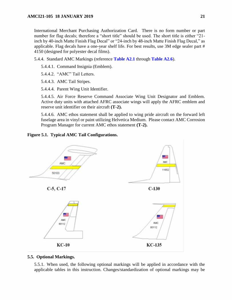
5.4.4. Standard AMC Markings (reference Table A2.1 through Table A2.6).
5.4.4.1. Command Insignia (Emblem).
5.4.4.2. “AMC” Tail Letters.
5.4.4.3. AMC Tail Stripes.
5.4.4.4. Parent Wing Unit Identifier.
5.4.4.5. Air Force Reserve Command Associate Wing Unit Designator and Emblem.
Active duty units with attached AFRC associate wings will apply the AFRC emblem and
reserve unit identifier on their aircraft (T-2).
5.4.4.6. AMC ethos statement shall be applied to wing pride aircraft on the forward left
fuselage area in vinyl or paint utilizing Helvetica Medium. Please contact AMC Corrosion
Program Manager for current AMC ethos statement (T-2).
Figure 5.1. Typical AMC Tail Configurations.
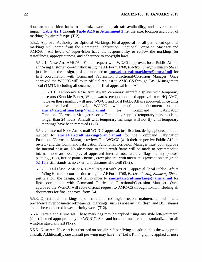
5.5. Optional Markings.
5.5.1. When used, the following optional markings will be applied in accordance with the
applicable tables in this instruction. Changes/standardization of optional markings may be
22 AMCI21-105 18 JANUARY 2019
done on an attrition basis to minimize workload, aircraft availability, and environmental
impact. Table A2.1 through Table A2.6 in Attachment 2 list the size, location and color of
markings by aircraft type (T-2).
5.5.2. Approval Authority for Optional Markings. Final approval for all permanent optional
markings will come from the Command Fabrication Functional/Corrosion Manager and
AMC/A4. All levels of supervision have the responsibility to review the markings for
tastefulness, appropriateness, and adherence to copyright laws.
5.5.2.1. Nose Art: AMC/A4. E-mail request with WG/CC approval, local Public Affairs
and Wing Historian coordination using the AF Form 1768, Electronic Staff Summary Sheet,
justification, the design, and tail number to [email protected] for
first coordination with Command Fabrication Functional/Corrosion Manager. Once
approved the WG/CC will route official request to AMC-CS through Task Management
Tool (TMT), including all documents for final approval from A4.
5.5.2.1.1. Temporary Nose Art: Award ceremony aircraft displays with temporary
nose arts (Knuckle Buster, Wing awards, etc.) do not need approval from HQ AMC,
however these marking will need WG/CC and local Public Affairs approval. Once units
have received approval, WG/CC will send all documentation to
[email protected] for Command Fabrication
Functional/Corrosion Manager records. Timeline for applied temporary markings is no
longer than 24 hours. Aircraft with temporary markings will not fly until temporary
markings have been removed (T-2)
5.5.2.2. Internal Nose Art: E-mail WG/CC approval, justification, design, photos, and tail
number to [email protected] for the Command Fabrication
Functional/Corrosion Manager review. The WG/CC (with their respective Public Affairs
review) and the Command Fabrication Functional/Corrosion Manager must both approve
the internal nose art. No alterations to the aircraft frame will be made to accommodate
internal nose art. Examples of approved internal nose art are; flags, family photos,
paintings, rugs, latrine paint schemes, crew placards with nicknames (exception paragraph
5.5.10.3 still stands as no external nicknames allowed) (T-2).
5.5.2.3. Tail Flash: AMC/A4. E-mail request with WG/CC approval, local Public Affairs
and Wing Historian coordination using the AF Form 1768, Electronic Staff Summary Sheet,
justification, the design, and tail number to [email protected] for
first coordination with Command Fabrication Functional/Corrosion Manager. Once
approved the WG/CC will route official request to AMC-CS through TMT, including all
documents for final approval from A4.
5.5.3. Operational markings and structural coating/corrosion maintenance will take
precedence over cosmetic refinements; markings, such as nose art, tail flash, and DCC names
should be considered lowest priority work (T-2).
5.5.4. Letters and Numerals. These markings may be applied using any style letter/numeral
(font) deemed appropriate by the WG/CC. Size and location must remain standardized for all
wing-assigned aircraft (T-2).
5.5.5. Nose Art. Nose art is authorized on one aircraft per flying squadron, plus the wing pride
aircraft. Additionally, one aircraft per wing may have the “Let’s Roll” graphic applied as nose
AMCI21-105 18 JANUARY 2019 23
art (not to exceed three feet in diameter); it may be on one of the above aircraft, or in addition
to the above aircraft. Nose art is not permitted on any aircraft flying missions where local
populations may consider it sensitive or offensive. Art will reflect a theme of civic and
community pride, be distinctive, symbolic, and designed and maintained to the highest quality
standards. Positioning of nose art is at the discretion of the WG/CC; however, it must be
forward of the wing leading edge and not interfere with any mandatory markings. Nose art
should be approximately two-thirds the size of the fuselage national star insignia, not to exceed
three feet in diameter. All nose art applied to wing aircraft will be of standard size and location.
Nose art and tail flash designs must be approved prior to installation (T-2).
5.5.5.1. On aircraft with lusterless paint schemes, nose art and tail flash must be applied
using lusterless paint and/or decals (T-2).
5.5.6. Aircraft Names. Aircraft Names are authorized on AMC aircraft only after approval by
USAF/CV. The proposed name must either have a national or military theme or honor a locale
adjacent to an AMC base or aircraft manufacturing point. Route recommendations through
your WG/CC to AMC-CS TMT; include the proposed name and detailed justification. If
applied in addition to nose art, the aircraft name and nose art must be complementary; the font,
size, and location may be changed to complement the nose art (T-2).
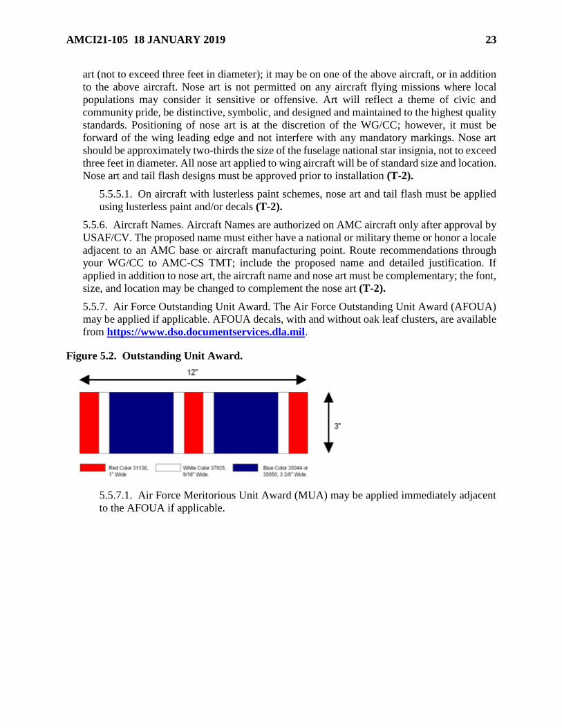
5.5.7. Air Force Outstanding Unit Award. The Air Force Outstanding Unit Award (AFOUA)
may be applied if applicable. AFOUA decals, with and without oak leaf clusters, are available
from https://www.dso.documentservices.dla.mil.
Figure 5.2. Outstanding Unit Award.
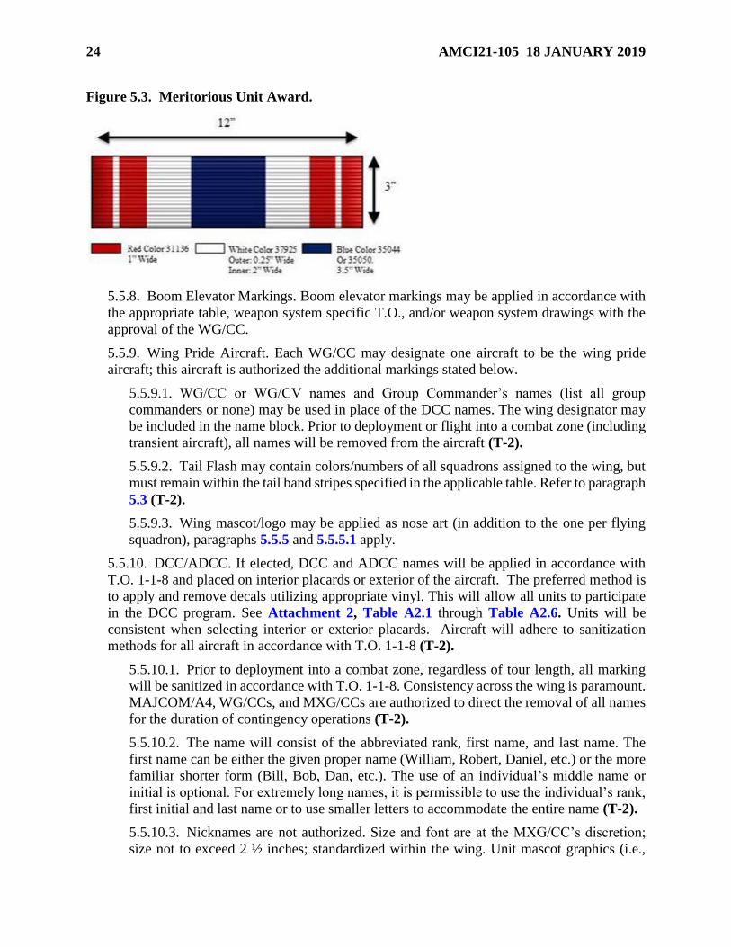
5.5.7.1. Air Force Meritorious Unit Award (MUA) may be applied immediately adjacent
to the AFOUA if applicable.
24 AMCI21-105 18 JANUARY 2019
Figure 5.3. Meritorious Unit Award.
5.5.8. Boom Elevator Markings. Boom elevator markings may be applied in accordance with
the appropriate table, weapon system specific T.O., and/or weapon system drawings with the
approval of the WG/CC.
5.5.9. Wing Pride Aircraft. Each WG/CC may designate one aircraft to be the wing pride
aircraft; this aircraft is authorized the additional markings stated below.
5.5.9.1. WG/CC or WG/CV names and Group Commander’s names (list all group
commanders or none) may be used in place of the DCC names. The wing designator may
be included in the name block. Prior to deployment or flight into a combat zone (including
transient aircraft), all names will be removed from the aircraft (T-2).
5.5.9.2. Tail Flash may contain colors/numbers of all squadrons assigned to the wing, but
must remain within the tail band stripes specified in the applicable table. Refer to paragraph
5.3 (T-2).
5.5.9.3. Wing mascot/logo may be applied as nose art (in addition to the one per flying
squadron), paragraphs 5.5.5 and 5.5.5.1 apply.
5.5.10. DCC/ADCC. If elected, DCC and ADCC names will be applied in accordance with
T.O. 1-1-8 and placed on interior placards or exterior of the aircraft. The preferred method is
to apply and remove decals utilizing appropriate vinyl. This will allow all units to participate
in the DCC program. See Attachment 2, Table A2.1 through Table A2.6. Units will be
consistent when selecting interior or exterior placards. Aircraft will adhere to sanitization
methods for all aircraft in accordance with T.O. 1-1-8 (T-2).
5.5.10.1. Prior to deployment into a combat zone, regardless of tour length, all marking
will be sanitized in accordance with T.O. 1-1-8. Consistency across the wing is paramount.
MAJCOM/A4, WG/CCs, and MXG/CCs are authorized to direct the removal of all names
for the duration of contingency operations (T-2).
5.5.10.2. The name will consist of the abbreviated rank, first name, and last name. The
first name can be either the given proper name (William, Robert, Daniel, etc.) or the more
familiar shorter form (Bill, Bob, Dan, etc.). The use of an individual’s middle name or
initial is optional. For extremely long names, it is permissible to use the individual’s rank,
first initial and last name or to use smaller letters to accommodate the entire name (T-2).
5.5.10.3. Nicknames are not authorized. Size and font are at the MXG/CC’s discretion;
size not to exceed 2 ½ inches; standardized within the wing. Unit mascot graphics (i.e.,
AMCI21-105 18 JANUARY 2019 25
razorback and eagle head [outlines or silhouettes]) may be used as the forward edge of the
placard or crew chief block. For standardization purposes, either all or none of the wing
aircraft will bear the graphic (T-2).
5.5.11. Wing/Squadron/Aircraft Maintenance Unit Colors. Each operational squadron may
have its colors and/or logos applied within the boundaries of the tail stripes, or the entire wing
may share one tail stripe design. Refer to paragraph 5.3.
5.6. Competition Aircraft.
5.6.1. Units participating in competitions will follow the guidelines established in competition
rules for aircraft appearance. Competitions should be considered "come as you are" and no
waivers will be granted. "Come as you are" is defined as no special effort, painting, or
additional markings applied to enhance or improve the overall appearance of the aircraft. This
includes polishing of metal surfaces, using commander type markings, etc (T-2).
5.7. Aircraft Transfer.
5.7.1. The following markings must be removed prior to formal transfer of aircraft to other
units or MAJCOMs (aircraft retiring to Aerospace Maintenance and Regeneration Group need
not have any markings removed). Deviations from transfer requirements are authorized
provided the gaining and losing units reach a mutual agreement (T-2).
5.7.1.1. Organizational insignias.
5.7.1.2. Unit identifier.
5.7.1.3. Tail stripe.
5.7.1.4. Aircrew and crew chief names.
5.7.1.5. Unit unique markings.
5.7.1.6. Nose art.
5.8. Waivers.
5.8.1. WG/CC must submit waiver requests to their Weapons System Manager and courtesy
copy AMC/A4M, Command Fabrication Functional/Corrosion Manager. Waivers that are in
violation of aircraft technical data will not be accepted. Waiver requests must include the
following: (T-2).
5.8.1.1. Clear statement of present procedure/marking.
5.8.1.2. Clear statement of proposed change.
5.8.1.3. Justification to include historical significance, if applicable.
5.8.1.4. Digital color photographs, one of present marking and one of requested change.
The use of a slide presentation format is allowed.
5.9. Photo Requirements.
5.9.1. All units must submit one full length (landscape orientation) digital photo of each
aircraft that has been approved for any or all of the following: “Let’s Roll” markings, nose
markings, names, and tail flashes. The use of a slide presentation format is allowed. Send to
AMC/A4M for review and file along with uploading approved documents to the HQ AMC

26 AMCI21-105 18 JANUARY 2019
A4/MR Fabrication Flight SharePoint site. AMC/A4M may request updated photos
periodically (T-2).
STEVEN J. BLEYMAIER, Brigadier General,
USAF
Director of Logistics, Engineering, and Force
Protection
AMCI21-105 18 JANUARY 2019 27
Attachment 1
GLOSSARY OF REFERENCES AND SUPPORTING INFORMATION
References
TO 00-25-107, Maintenance Assistance, 01 October 2015
TO 00-25-172, Ground Servicing of Aircraft and Static Grounding/Bonding, 13 March 2017
TO 00-25-252, Aeronautical Equipment Welding, 01 October 2016
TO 1-1-689-3, Cleaning and Corrosion Control Volume III Avionics and Electronics, 15 January
2016
TO 1-1-690, General Advanced Composite Repair Processes Manual, 08 November 2016
TO 1-1-691, Cleaning and Corrosion Prevention and Control, Aerospace and Non-Aerospace
Equipment, 29 September 2018
TO 1-1-8, Application and Removal of Organic Coatings, Aerospace and Non-Aerospace
Equipment, 10 August 2018
TO 1-1-9, Aerospace Metals – General Data and Usage Factors, 30 July 2018
TO 1C-135-3-8, Exterior Stencils, USAF Series -135 Aircraft, 01 April 2017
TO 32-1-101, Use and Care of Hand Tools and Measuring Tools, 26 April 2017
TO 33B-1-1, Nondestructive Inspection Methods, Basic Theory, 15 October 2016
TO 34-1-3, Machinery and Shop Equipment, 21 December 2017
TO 35-1-3, Corrosion Prevention and Control, Cleaning, Painting and Marking of USAF
Support Equipment (SE), 20 May 2018
AFI 20-114, Air and Space Equipment Structural Maintenance, 07 June 2011
AFI 21-101, Aircraft and Equipment Maintenance Management, 21 May 2015
AFI 21-124, Oil Analysis Program, 12 January 2017
AFI 32-1024, Standard Facility Requirements, 14 July 2011
AFI 48-148, Ionizing Radiation Protection, 20 November 2014
AFMAN 32-1084, Facility Requirements, 26 February 2016
AFMAN 33-363, Management of Records, 01 March 2008
AFMAN 48-125, Personnel Ionizing Radiation Dosimetry, 09 January 2019
AFMAN 91-203, Air Force Occupational Safety, Fire, and Health Standards, 11 December
2018
Prescribed Forms
AFMC Form 1017, Aircraft Wash Supervisor and Employee’s Certification
28 AMCI21-105 18 JANUARY 2019
Adopted Forms
DD Form 2757, Welding Examination Record
AFTO Form 781A, Maintenance Discrepancy and Work Document
AFTO Form 95, Significant Historical Data
AF Form 1768, Staff Summary Sheet
AF Form 847, Recommendation for Change of Publication
Abbreviations and Acronyms
ADCC—Assistant Dedicated Crew Chief
AFI—Air Force Instruction
AFCPCO—Air Force Corrosion Prevention and Control Office
AFOUA—Air Force Outstanding Unit Award
AFRC—Air Force Reserve Command
AFSC—Air Force Specialty Code
AGE—Aerospace Ground Equipment
ALC—Air Logistics Center or Air Logistics Complex
AM—Additive Manufacturing
AMC—Air Mobility Command
AMT—Aircraft Metals Technology
ANG—Air National Guard
ASIP—Aircraft Structural Integrity Program
ASM—Aircraft Structural Maintenance
CC—Commander
CCPE—Corrosion Prevention Advisory Board
COR—Contracting Officer Representative
CPAB—Corrosion Prevention Advisory Board
CV—Vice Commander
DCC—Dedicated Crew Chief
DoD—Department of Defense
FRP—Fuselage Reference Plane
HQ—Headquarters
IAW—In Accordance With
IMI—Interactive Multimedia Instruction
AMCI21-105 18 JANUARY 2019 29
IPT—Integrated Process Teams
MAF—Mobility Air Forces
MAJCOM—Major Command
MDS—Mission Design Series
MIS—Maintenance Information System
MTO—Metals Technology Office
MXG—Maintenance Group
MXS—Maintenance Squadron
NAS 410—National Aerospace Standard Certification & Qualification of Nondestructive Test
Personnel
NDI—Nondestructive Inspection
OAP—Oil Analysis Program
OPR—Office of Primary Responsibility
OWS—Outer Wing Station
PA—Public Affairs
PCAMS—Process Control Automated Management System
PCR—Publication Change Request
PE—Personal Evaluation
PIT—Product Improvement Team
POC—Point of Contact
POM—Program Objective Memoranda
PPE—Personal Protective Equipment
QA—Quality Assurance
QPD—Qualified Product Database
QPL—Qualified Products Listings
RVSM—Reduced Vertical Separation Minimum
SE—Support Equipment
SNCO—Senior Noncommissioned Officer
SPO—System Program Officer
TDY—Temporary Duty
TO—Technical Order
USAF—United States Air Force
U&TW—Utilization and Training Workshop

30 AMCI21-105 18 JANUARY 2019
VSS—Vertical Stab Station
WG—Wing
W&B—Weight and Balance
AMCI21-105 18 JANUARY 2019 31
Attachment 2
MARKING LOCATION BY AIRFRAME
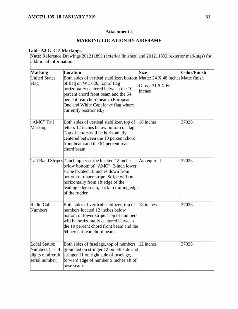
Table A2.1. C-5 Markings.
Note: Reference Drawings 201211891 (exterior finishes) and 201211892 (exterior markings) for
additional information.
Marking Location Size Color/Finish
United States
Flag
Both sides of vertical stabilizer, bottom
of flag on WL 626, top of flag
horizontally centered between the 10
percent chord front beam and the 64
percent rear chord beam. (European
One and White Cap; leave flag where
currently positioned.)
Matte: 24 X 48 inches
Gloss: 31.5 X 60
inches
Matte finish
“AMC” Tail
Marking
Both sides of vertical stabilizer, top of
letters 12 inches below bottom of flag.
Top of letters will be horizontally
centered between the 10 percent chord
front beam and the 64 percent rear
chord beam.
18 inches 37038
Tail Band Stripes 2-inch upper stripe located 12 inches
below bottom of “AMC”. 2-inch lower
stripe located 18 inches down from
bottom of upper stripe. Stripe will run
horizontally from aft edge of the
leading edge seam, back to trailing edge
of the rudder.
As required 37038
Radio Call
Numbers
Both sides of vertical stabilizer, top of
numbers located 12 inches below
bottom of lower stripe. Top of numbers
will be horizontally centered between
the 10 percent chord front beam and the
64 percent rear chord beam.
18 inches 37038
Local Station
Numbers (last 4
digits of aircraft
serial number)
Both sides of fuselage, top of numbers
grounded on stringer 12 on left side and
stringer 11 on right side of fuselage,
forward edge of number 9 inches aft of
nose seam.
12 inches 37038
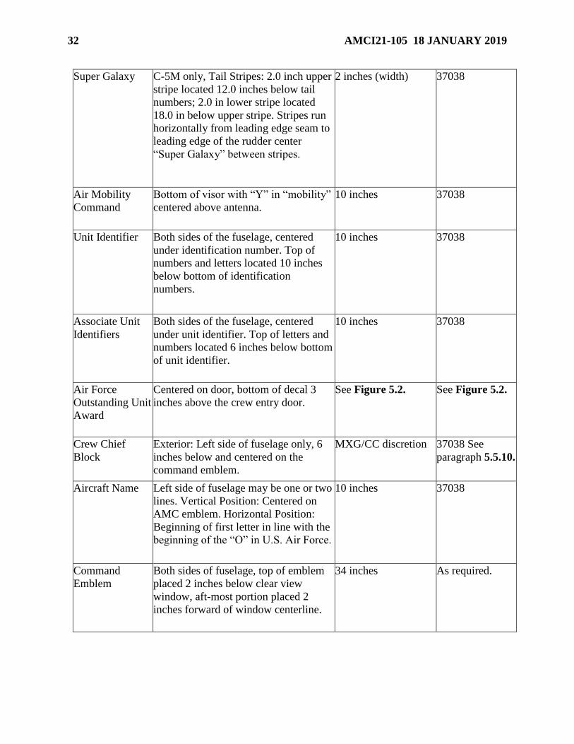
32 AMCI21-105 18 JANUARY 2019
Super Galaxy C-5M only, Tail Stripes: 2.0 inch upper
stripe located 12.0 inches below tail
numbers; 2.0 in lower stripe located
18.0 in below upper stripe. Stripes run
horizontally from leading edge seam to
leading edge of the rudder center
“Super Galaxy” between stripes.
2 inches (width) 37038
Air Mobility
Command
Bottom of visor with “Y” in “mobility”
centered above antenna.
10 inches 37038
Unit Identifier Both sides of the fuselage, centered
under identification number. Top of
numbers and letters located 10 inches
below bottom of identification
numbers.
10 inches 37038
Associate Unit
Identifiers
Both sides of the fuselage, centered
under unit identifier. Top of letters and
numbers located 6 inches below bottom
of unit identifier.
10 inches 37038
Air Force
Outstanding Unit
Award
Centered on door, bottom of decal 3
inches above the crew entry door.
See Figure 5.2. See Figure 5.2.
Crew Chief
Block
Exterior: Left side of fuselage only, 6
inches below and centered on the
command emblem.
MXG/CC discretion 37038 See
paragraph 5.5.10.
Aircraft Name Left side of fuselage may be one or two
lines. Vertical Position: Centered on
AMC emblem. Horizontal Position:
Beginning of first letter in line with the
beginning of the “O” in U.S. Air Force.
10 inches 37038
Command
Emblem
Both sides of fuselage, top of emblem
placed 2 inches below clear view
window, aft-most portion placed 2
inches forward of window centerline.
34 inches As required.
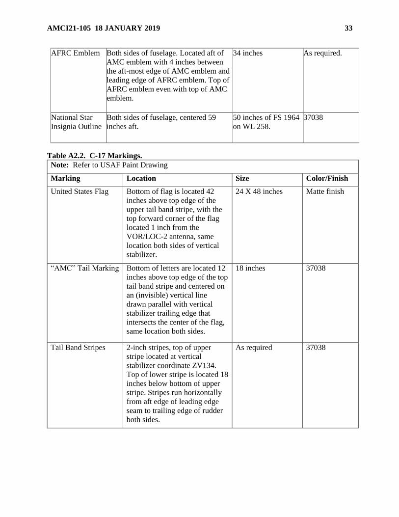
AMCI21-105 18 JANUARY 2019 33
AFRC Emblem Both sides of fuselage. Located aft of
AMC emblem with 4 inches between
the aft-most edge of AMC emblem and
leading edge of AFRC emblem. Top of
AFRC emblem even with top of AMC
emblem.
34 inches As required.
National Star
Insignia Outline
Both sides of fuselage, centered 59
inches aft.
50 inches of FS 1964
on WL 258.
37038
Table A2.2. C-17 Markings.
Note: Refer to USAF Paint Drawing
Marking Location Size Color/Finish
United States Flag Bottom of flag is located 42
inches above top edge of the
upper tail band stripe, with the
top forward corner of the flag
located 1 inch from the
VOR/LOC-2 antenna, same
location both sides of vertical
stabilizer.
24 X 48 inches Matte finish
“AMC” Tail Marking Bottom of letters are located 12
inches above top edge of the top
tail band stripe and centered on
an (invisible) vertical line
drawn parallel with vertical
stabilizer trailing edge that
intersects the center of the flag,
same location both sides.
18 inches 37038
Tail Band Stripes 2-inch stripes, top of upper
stripe located at vertical
stabilizer coordinate ZV134.
Top of lower stripe is located 18
inches below bottom of upper
stripe. Stripes run horizontally
from aft edge of leading edge
seam to trailing edge of rudder
both sides.
As required 37038
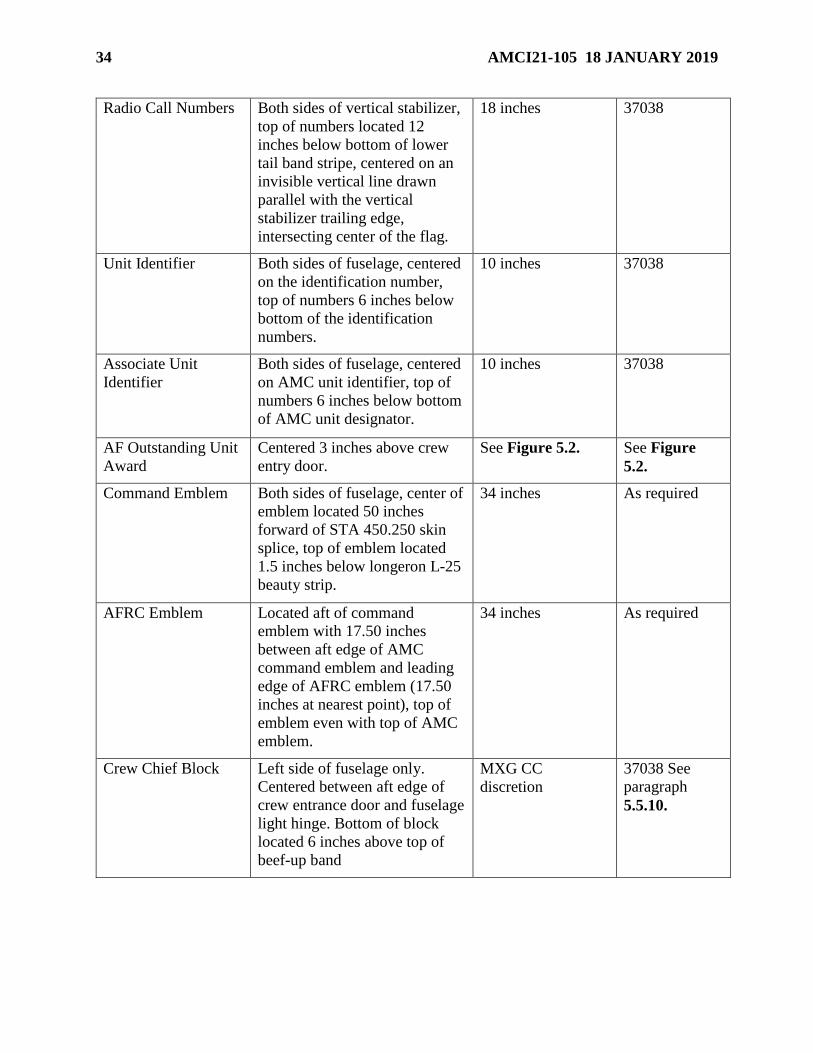
34 AMCI21-105 18 JANUARY 2019
Radio Call Numbers Both sides of vertical stabilizer,
top of numbers located 12
inches below bottom of lower
tail band stripe, centered on an
invisible vertical line drawn
parallel with the vertical
stabilizer trailing edge,
intersecting center of the flag.
18 inches 37038
Unit Identifier Both sides of fuselage, centered
on the identification number,
top of numbers 6 inches below
bottom of the identification
numbers.
10 inches 37038
Associate Unit
Identifier
Both sides of fuselage, centered
on AMC unit identifier, top of
numbers 6 inches below bottom
of AMC unit designator.
10 inches 37038
AF Outstanding Unit
Award
Centered 3 inches above crew
entry door.
See Figure 5.2. See Figure
5.2.
Command Emblem Both sides of fuselage, center of
emblem located 50 inches
forward of STA 450.250 skin
splice, top of emblem located
1.5 inches below longeron L-25
beauty strip.
34 inches As required
AFRC Emblem Located aft of command
emblem with 17.50 inches
between aft edge of AMC
command emblem and leading
edge of AFRC emblem (17.50
inches at nearest point), top of
emblem even with top of AMC
emblem.
34 inches As required
Crew Chief Block Left side of fuselage only.
Centered between aft edge of
crew entrance door and fuselage
light hinge. Bottom of block
located 6 inches above top of
beef-up band
MXG CC
discretion
37038 See
paragraph
5.5.10.
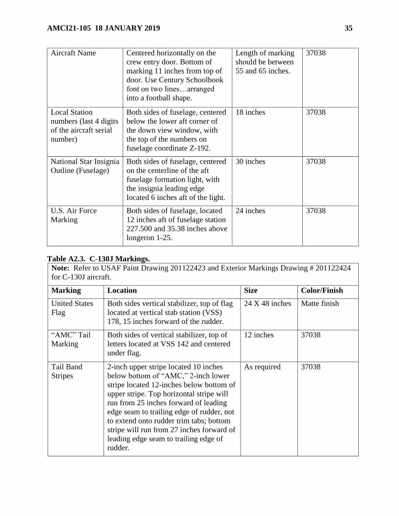
AMCI21-105 18 JANUARY 2019 35
Aircraft Name Centered horizontally on the
crew entry door. Bottom of
marking 11 inches from top of
door. Use Century Schoolbook
font on two lines…arranged
into a football shape.
Length of marking
should be between
55 and 65 inches.
37038
Local Station
numbers (last 4 digits
of the aircraft serial
number)
Both sides of fuselage, centered
below the lower aft corner of
the down view window, with
the top of the numbers on
fuselage coordinate Z-192.
18 inches 37038
National Star Insignia
Outline (Fuselage)
Both sides of fuselage, centered
on the centerline of the aft
fuselage formation light, with
the insignia leading edge
located 6 inches aft of the light.
30 inches 37038
U.S. Air Force
Marking
Both sides of fuselage, located
12 inches aft of fuselage station
227.500 and 35.38 inches above
longeron 1-25.
24 inches 37038
Table A2.3. C-130J Markings.
Note: Refer to USAF Paint Drawing 201122423 and Exterior Markings Drawing # 201122424
for C-130J aircraft.
Marking Location Size Color/Finish
United States
Flag
Both sides vertical stabilizer, top of flag
located at vertical stab station (VSS)
178, 15 inches forward of the rudder.
24 X 48 inches Matte finish
“AMC” Tail
Marking
Both sides of vertical stabilizer, top of
letters located at VSS 142 and centered
under flag.
12 inches 37038
Tail Band
Stripes
2-inch upper stripe located 10 inches
below bottom of “AMC,” 2-inch lower
stripe located 12-inches below bottom of
upper stripe. Top horizontal stripe will
run from 25 inches forward of leading
edge seam to trailing edge of rudder, not
to extend onto rudder trim tabs; bottom
stripe will run from 27 inches forward of
leading edge seam to trailing edge of
rudder.
As required 37038

36 AMCI21-105 18 JANUARY 2019
Radio Call
Numbers
Both sides of vertical stabilizer, top of
numbers located 10 inches below bottom
of lower tail band stripe, centered under
flag.
15 inches 37038
Local Station
Numbers (Last
4 digits of
aircraft serial
number)
Placed on both sides of fuselage, 23
inches aft of pilot’s kick window.
Bottom of marking parallel to bottom of
pilot’s kick window.
6 inches 37038
“U.S. AIR
FORCE”
Fuselage
Marking
Both sides of forward fuselage 14 inches
aft of the window frame and horizontally
level with the lower window.
15 inches 37038
Unit Identifier Both sides of fuselage, 6 inches below
local station numbers. Forward edge of
unit identifier to be in line with first digit
of local station numbers. Note: Ensure
markings do not migrate into the
Reduced Vertical Separation Minimum
(RVSM) area.
6 inches
37038
Air Force
Outstanding
Unit Award
Centered 3 inches above crew entry
door.
See Figure 5.2.
See Figure 5.2.
Crew Chief
Block
Left side of fuselage only, 2 inches
forward of crew entry door in line with
top door seam
MXG/CC
discretion
37038 See
paragraph
5.5.10.
Command
Emblem
Both sides of fuselage, top of emblem
level and even with top edge of side
hatch, center of patch is 128” forward of
side hatch forward edge (approximately
FS 277.0E). (Long J model only)
24 inches
Short Models
no command
emblem
required
As required.
National Star
Insignia
Outline
Both sides of fuselage; see applicable
USAF drawing.
30 inches 37038
Ice Detection
Marking
Installed on both wing leading edges,
beginning at Outer Wing Stations
(OWS) 517.0 and extending outboard
and ending at OWS 541.0. Chordwise
dimension equals 12 inches on upper and
lower surfaces of leading edge.
24 X 24 inches 37038
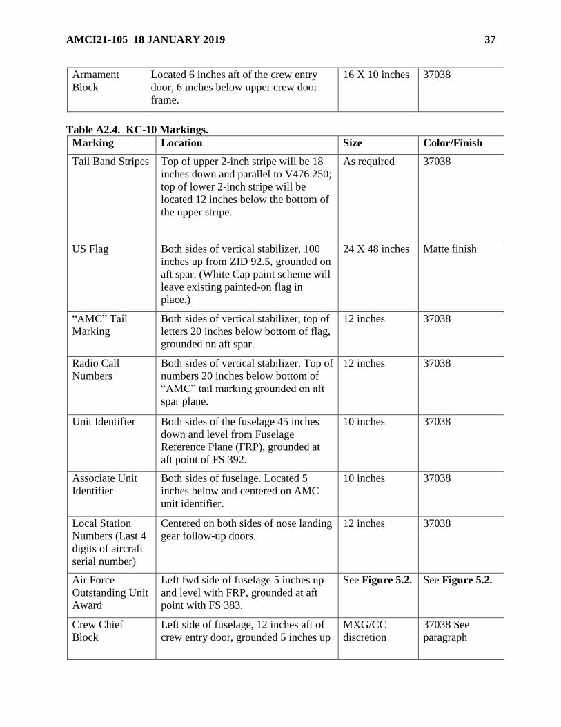
AMCI21-105 18 JANUARY 2019 37
Armament
Block
Located 6 inches aft of the crew entry
door, 6 inches below upper crew door
frame.
16 X 10 inches 37038
Table A2.4. KC-10 Markings.
Marking Location Size Color/Finish
Tail Band Stripes Top of upper 2-inch stripe will be 18
inches down and parallel to V476.250;
top of lower 2-inch stripe will be
located 12 inches below the bottom of
the upper stripe.
As required 37038
US Flag Both sides of vertical stabilizer, 100
inches up from ZID 92.5, grounded on
aft spar. (White Cap paint scheme will
leave existing painted-on flag in
place.)
24 X 48 inches Matte finish
“AMC” Tail
Marking
Both sides of vertical stabilizer, top of
letters 20 inches below bottom of flag,
grounded on aft spar.
12 inches 37038
Radio Call
Numbers
Both sides of vertical stabilizer. Top of
numbers 20 inches below bottom of
“AMC” tail marking grounded on aft
spar plane.
12 inches 37038
Unit Identifier Both sides of the fuselage 45 inches
down and level from Fuselage
Reference Plane (FRP), grounded at
aft point of FS 392.
10 inches 37038
Associate Unit
Identifier
Both sides of fuselage. Located 5
inches below and centered on AMC
unit identifier.
10 inches 37038
Local Station
Numbers (Last 4
digits of aircraft
serial number)
Centered on both sides of nose landing
gear follow-up doors.
12 inches 37038
Air Force
Outstanding Unit
Award
Left fwd side of fuselage 5 inches up
and level with FRP, grounded at aft
point with FS 383.
See Figure 5.2.
See Figure 5.2.
Crew Chief
Block
Left side of fuselage, 12 inches aft of
crew entry door, grounded 5 inches up
MXG/CC
discretion
37038 See
paragraph
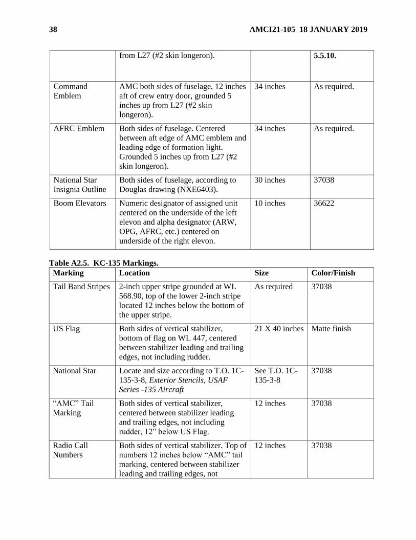
38 AMCI21-105 18 JANUARY 2019
from L27 (#2 skin longeron). 5.5.10.
Command
Emblem
AMC both sides of fuselage, 12 inches
aft of crew entry door, grounded 5
inches up from L27 (#2 skin
longeron).
34 inches As required.
AFRC Emblem Both sides of fuselage. Centered
between aft edge of AMC emblem and
leading edge of formation light.
Grounded 5 inches up from L27 (#2
skin longeron).
34 inches As required.
National Star
Insignia Outline
Both sides of fuselage, according to
Douglas drawing (NXE6403).
30 inches 37038
Boom Elevators Numeric designator of assigned unit
centered on the underside of the left
elevon and alpha designator (ARW,
OPG, AFRC, etc.) centered on
underside of the right elevon.
10 inches 36622
Table A2.5. KC-135 Markings.
Marking Location Size Color/Finish
Tail Band Stripes 2-inch upper stripe grounded at WL
568.90, top of the lower 2-inch stripe
located 12 inches below the bottom of
the upper stripe.
As required 37038
US Flag Both sides of vertical stabilizer,
bottom of flag on WL 447, centered
between stabilizer leading and trailing
edges, not including rudder.
21 X 40 inches Matte finish
National Star Locate and size according to T.O. 1C-
135-3-8, Exterior Stencils, USAF
Series -135 Aircraft
See T.O. 1C-
135-3-8
37038
“AMC” Tail
Marking
Both sides of vertical stabilizer,
centered between stabilizer leading
and trailing edges, not including
rudder, 12” below US Flag.
12 inches 37038
Radio Call
Numbers
Both sides of vertical stabilizer. Top of
numbers 12 inches below “AMC” tail
marking, centered between stabilizer
leading and trailing edges, not
12 inches 37038

AMCI21-105 18 JANUARY 2019 39
including rudder.
Unit Identifier Both sides of the fuselage, centered,
and 6 inches under identification
numbers.
6 inches
37038
Associate Unit
Identifier
Both sides of fuselage. Located 6
inches below and centered on AMC
unit identifier.
6 inches 37038
Local Station
Numbers (Last 4
digits of aircraft
serial number)
Both sides of fuselage. Locate
according to TO 1C-135-3-8.
6 inches 37038
Air Force
Outstanding Unit
Award
Centered 3 inches above the crew
entry door.
See Figure
5.2.
See Figure 5.2.
Crew Chief
Block
Left side of fuselage only; 6 inches
below and centered on the command
emblem.
MXG/CC
discretion
37038 See
paragraph 5.5.10.
Command
Emblem
Both sides of fuselage, 16 inches aft of
crew entry door, 6 inches below USAF
markings. (Do not paint “US Air
Force” on camouflage aircraft.)
34 inches As required.
AFRC Emblem Both sides of fuselage. Most forward
leading edge will be located 14 3/8
inches aft of the most aft edge and
aligned with the top of the AMC decal.
34 inches As required.
Boom Elevators Highest numeric designator of station
assigned (22d, 458th, 905th, etc.)
centered on the underside of the left
ruddervator and alpha designator
(ARW, OPG, AFRC, etc.) centered on
underside of the right ruddervator.
10 inches 36622
Table A2.6. KC-46 Markings.
Note: Only mandatory markings are allowed. Leave all markings as manufacture produced.
No waivers or optional markings will be accepted. Follow aircraft specific TO/Commercial
Manual for Grey Tail markings guidance. Internal Nose Art authorized with proper routing.
Marking Location Size Color/Finish
US Flag See TO/ Commercial Manual See TO/
Commercial
See TO/
Commercial
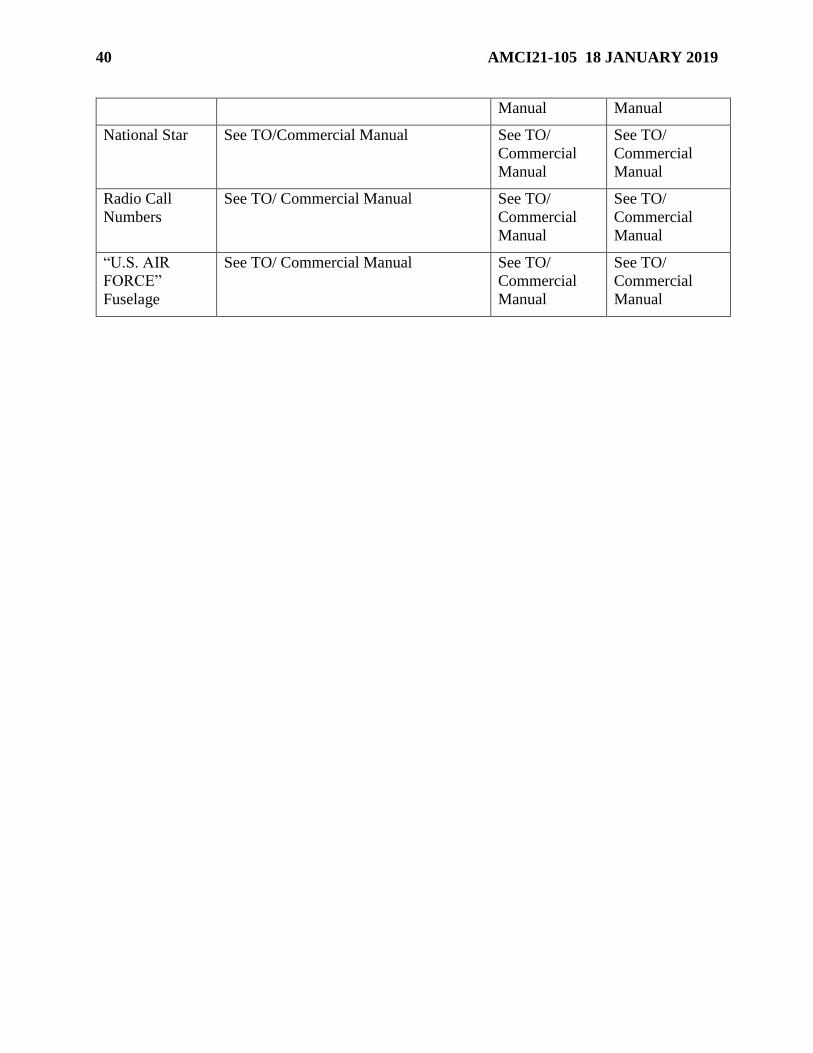
40 AMCI21-105 18 JANUARY 2019
Manual Manual
National Star See TO/Commercial Manual See TO/
Commercial
Manual
See TO/
Commercial
Manual
Radio Call
Numbers
See TO/ Commercial Manual See TO/
Commercial
Manual
See TO/
Commercial
Manual
“U.S. AIR
FORCE”
Fuselage
See TO/ Commercial Manual See TO/
Commercial
Manual
See TO/
Commercial
Manual