by order of the commander amci24-101v7cl...
TRANSCRIPT

BY ORDER OF THE COMMANDER AMCI24-101V7CL-2 AIR MOBILITY COMMAND 1 AUGUST 2013
Transportation
C-5 AERIAL PORT EXPEDITOR (APEX) LOAD DIRECTOR CHECKLIST
COMPLIANCE WITH THIS PUBLICATION IS MANDATORY
ACCESSIBILITY: Publications and forms are available on the e- Publishing website at www.e-publishing .af.mil for downloading or ordering.
RELEASABILITY: There are no releasability restrictions on this publication.
OPR: HQ AMC/A4TC Certified by: HQ AMC/A4T (Col William Z. Zeck)
Supersedes: AMCI24-101V7CL-2, 1 December 2008
This checklist complements AMCI 24-101V7, AMC Aerial Port Expeditor, and is formatted so that it may be trimmed down to fit aircrew style checklist binders. It is a total revision of the previous checklist to match mission requirements of the AMC APEX program. Ensure that all records created as a result of processes prescribed in this publication are maintained IAW Air Force Manual (AFMAN) 33-363, Management of Records, and disposed of IAW Air Force Records Information Management System (AFRIMS) Records Disposition Schedule (RDS).
Squadron:_
Section:_
Name/Number:_

AMCI 24-101V7, CL-2 (C-5)
C-5 AERIAL PORT EXPEDITOR (APEX) LOAD DIRECTOR CHECKLIST
TABLE OF CONTENTS
PAGE
1. GENERAL INFORMATION 3
2. LOAD PLANNING CHECKLIST 4
3. GENERAL INSTRUCTIONS: 5 3.1 CARGO LOADING PREPARATION
4. AIRCRAFT PREFLIGHT: 10
EXTERIOR
5. AIRCRAFT PREFLIGHT: 11 INTERIOR
6. PALLETIZED CARGO LOADING CHECKLIST 14
7. VEHICLE LOADING CHECKLIST 17
8. CARGO OFF LOADING CHECKLIST 21
9. C-5A CARGO WINCH OPERATING PROCEDURES 24
10. C-5B CARGO WINCH OPERATING PROCEDURES 32
11. ELECTRIC WINCH ON C5B and C5 41
12. AFTER LOADING CHECKLIST 46
13. EMERGENCY PROCEDURES 47

AMCI 24-101V7, CL-2 (C-5) 3
1. GENERAL INFORMATION
1.1. Items in this checklist are excerpts from the rele- vant portions of the basic aircraft flight manuals/ loading instructions (T.O. 1C-5A-1 and T.O. 1C-5A- 9, T.O. 1C-5M-1 and T.O. 1C-5M-9 ) are for use by APEX load directors. If conflict arises between this checklist and the T.O. checklists, the T.O. checklists will always take precedence.
1.2. Warnings, Cautions, and Notes. The following definitions apply to WARNINGS, CAUTIONS, and NOTES found in this checklist.
WARNING
1.2.1. Operating procedures, techniques, etc., which could result in personal injury and/or loss of life if not
carefully followed.
CAUTION
1.2.2. Operating procedures, techniques, etc., which could result in damage to equipment if not carefully
followed.
NOTE
1.2.3. An operating procedure, technique, etc., which is considered essential to emphasize.

AMCI 24-101V7, CL-2 (C-5) 4
2. LOAD PLANNING CHECKLIST
1. Load Plan CHECKED
2. Operating Weight and Moment Match CHECKED / Current Configuration CALCULATE
3. Allowable Cabin Load CHECKED
4. Zero Fuel CG CHECKED
Ensure all weights, moments, and CG are accurate
5. Load Sequence CHECKED
Load sequence will be based on airplane limitations and offload sequence
6. Onload/Thru-load Hazardous CHECKED
Materials/Special Handling
7. Size, Weight, Location CHECKED
8. Shipper’s Declaration of CHECKED Dangerous Goods (ONE COPY
PER HAZARD)
9. Onload/Thru-Load Hazardous CHECKED Compatibility/Separation AFMAN 24-204 ATTACHMENT 18
10. Passenger Deviations CHECKED
(AS REQUIRED)
11. Refrigerated Material CHECKED
12. Cargo Size Limitations /ATTLA Certs CHECKED
13. Cargo Floor Loading Limitations CHECKED
14. Lateral Loading Limitations CHECKED
15. Venting Requirements CHECKED

5 AMCI 24-101V7, CL-2 (C-5)
3. GENERAL INSTRUCTIONS: CARGO LOADING PREPARATION
3.1 PALLETIZED CARGO
CAUTION
Any vehicle/item that exceeds the limitation/procedures of this manual shall have the specific approval of WR-ALC/ LATET or a letter of air transportability certification from ASC/ENFC or shall not be airlifted. Failure to comply could result in structural damage to the aircraft
NOTE
It is not acceptable to take a pallet that has been rejected for airlift (missing rings, delaminated, etc.) and place it on top of another pallet to airlift it. If the pallet has been re- jected for airlift, it shall not be used in any way to support cargo.
1. Condition of Pallet and Nets CHECKED
2. Security of Nets CHECKED
3. Low Profile Cargo CHECKED
A. Cargo weight does not exceed 2,500 lbs. B. Cargo height not exceeding 45 inches from top of pallet C. All hooks are serviceable and attached to pallet rings
4. Dimensions CHECKED
NOTE
The height of cargo weighing 10,000 pounds on a single pallet secured with nets is limited to 96 inches and 100 inches for cargo weighing 8,000 pounds.
5. Ramp Pallets CHECKED

AMCI 24-101V7, CL-2 (C-5) 6
NOTE
Pallets to be loaded in positions 1, 2, 35, and 36 shall have a 14-inch aisle on the outboard edge and not exceed 7,500 lb gross weight each. Additionally, pallets loaded in posi- tions 35 and 36 shall be limited to a maximum height of 70 inches at the aft edge of the pallet.
6. Small Wheeled and Skidded Cargo CHECKED
7. Pallet Identifier CHECKED
8. Pallet Train and Un-netted Pallets INSPECTED
NOTE
To ensure vertical clearance when near the cargo compart- ment sidewall, position palletized cargo with an outboard height of 114 inches or greater or with lateral overhang, out of the logistics restraint rail system. Do not exceed 108 inches above the surface of the pallet when loaded through the aft doors or 156 inches when loaded through the forward doors.
9. Pallet Train Dimensions CHECKED
10. Pallet Rings and Couplers CHECKED
11. Center of Balance CHECKED
12. Roller Load Limitations CHECKED
13. Hazardous Cargo CHECKED
14. Size, Weight and Location Limitations CHECKED
15. Shipper’s Declaration of Dangerous CHECKED
Goods and Label(s)
16. Compatibility and Separation Requirements CHECKED

7 AMCI 24-101V7, CL-2 (C-5)
NOTE
Hazardous cargo that is considered jettisonable shall not be positioned forward of non-jettisonable cargo, except when its size, weight, and location will permit jettisoning by hand. Depending upon the amount of hazardous cargo, placement aboard the aircraft should normally be planned for the aft section of the cargo compartment. Hazardous cargo will never be loaded in such a manner that would make jettisoning impossible.
17. Standing water/snow removed from pallets CHECKED
18. Soil Contamination and Pests CHECKED
19. Load sequenced/secured aboard MHE CHECKED
20. Loading crew BRIEFED
Identify Upwind Evacuation Location
3.2 VEHICLE INSPECTION CHECKLIST
1. Soil Contamination and Pests CHECKED
2. Fluid Leaks CHECKED
3. Condition of Tires and Tracks CHECKED
4. Tanker Type/Fire Fighting Vehicles CHECKED
NOTE
Check for the presence of liquids. Tanker type vehicles (trailer or self-contained) are not normally certified as air transportable in a loaded configuration (liquid in tank). The structural integrity of most tanker type vehicles does not meet the design criteria to withstand the G forces encoun- tered during flight. (Exceptions: The M-149A2 water trailer has been certified for airlift, provided the tank is no more than ¾ full and the manhole cover is secured with tiedown straps. Fire fighting vehicles are certified for transport with up to 150 gallons of AFFF (foam agent) in the tank.)

AMCI 24-101V7, CL-2 (C-5) 8
5. Shippers Declaration of Dangerous CHECKED / Goods, Label(s), and Cert. Ltr AS REQUIRED
6. Loose Equipment and Secondary Cargo CHECKED /
Check that all loose equipment and SECURED secondary cargo is secured.
7. Battery CHECKED /
SECURED
8. Filler Caps CHECKED Ensure fuel, oil, and any other appropriate filler caps are tight and secure.
9. Fuel Levels CHECKED
AFMAN(I) 24-204, Contingency vs. Channel
10. Trailer Forward Support Leg(s)/Wheel(s) SECURED
11. Vehicle Weights CHECKED
12. Gross Weight CHECKED
13. Vehicle(s) Center of Balance CHECKED (Loaded or Empty)
14. Axle Weights CHECKED
15. Wheel Weights COMPUTED
16. Geometric Considerations CHECKED
A. Vehicle Size Limitations CHECKED
B. Loading Overhang Limits CHECKED
C. Vehicle Projection Limits CHECKED
D. Ramp Crest Limits CHECKED
E. Parking Overhang Clearance Limits CHECKED

9 AMCI 24-101V7, CL-2 (C-5)
17. Structural Considerations CHECKED
A. Forward/Aft Ramp On/Off CHECKED Loading Limitations
B. Rolling Shoring Requirements COMPUTED /
AS REQUIRED
C. Cargo Floor Loading Limitations CHECKED
D. Concentrated Floor Loads CHECKED
E. Hard Rubber Tire and Steel Wheel CHECKED Limitations
F. Lateral Loading Limitations CHECKED
G. Parking Shoring Requirements COMPUTED /
AS REQUIRED
H. Sleeper Shoring Requirements COMPUTED / AS REQUIRED
NOTE
Ensure all required certifications for loading (ATTLA) are provided and utilized for loading operations.

NOTE
NOTE
AMCI 24-101V7, CL-2 (C-5) 10
4. AIRCRAFT PREFLIGHT: EXTERIOR
1. Aircraft Tail Number/Parking Spot CHECKED Aircraft parked in a designated hazardous cargo loading area?
2. Fire bottle POSITIONED /
SERVICABLE
3. Aircraft Configuration CHECKED
NOTE
If aircraft is in a forward kneel, check that the 4" collars are installed on both aft main gear struts. For aft kneel, check that the 4" & 2.75" collars are installed on the forward main gear struts. Kneeling collars are not required for level kneeling.
CAUTION
Ensure the bottom of the yoke for each gear contacts the shoulder on the shock strut or top of kneeling collar as applicable. If contact is not made, do not accomplish cargo loading/unloading operations until maintenance action is accomplished on the malfunctioning gear
4. Nose Landing Gear Downlock Pin CHECKED
5. Aircraft Electrically Grounded CHECKED
6. Main Landing Gear Wheel Chocks IN PLACE
NOTE
Check main gear wheel chocks forward and aft. Chocks should be three inches from wheels.

11 AMCI 24-101V7, CL-2 (C-5)
5. AIRCRAFT PREFLIGHT: INTERIOR
1. AFTO Form 781 Series CHECKED
NOTE
Ensure there are no Red X’s or deficiencies that prohibit aircraft on/off loading.
2. Parking Brake Set CHECKED
NOTE
Have maintenance crew chief ensure the aircraft brake se- lector is set to emergency and that aircraft parking brakes are set.
3. Electrical Power AS REQUIRED
4. Interior lights AS REQUIRED
5.1 CARGO COMPARTMENT: LEFT SIDE
1. Cargo Compartment Lights AS REQUIRED
2. Snatch Block Check general condition of pulley, hook latch quick release pin, and stop. Open the snatch block and ensure the snap ring secures the pulley in place CHECKED /
AS REQUIRED
3. Cargo Compartment Vent CHECKED / AS REQUIRED
4. Tiedown Equipment CHECKED
5. Cargo Compartment Vent CHECKED /
AS REQUIRED
6. Remote Control Grip Assembly CHECKED / Check condition and plug into receptacle. POWER OFF On the C5B hydraulic pendant , rotate thumbwheel and check that it returns to center.

AMCI 24-101V7, CL-2 (C-5) 12
7. Stowage Box CHECKED A. Pallet Stops (2) B. Detent Locking Tees (8)
8. Cargo Compartment Vent CHECKED
9. Retractable Rail CHECKED /
PIN INSTALLED
10. LH Inboard Rail Connector CHECKED / STOWED
11. Troop Compartment Ladder POSITIONED /
Cargo Clearance VERIFIED
12. “A-frame” Rail CHECKED / STOWED
13. Pressure Door Seals/Side Slopping Longeron
Check for visible damage CHECKED
5.2 CARGO COMPARTMENT: RIGHT SIDE
1. Aft Winch and Compartment Hatch CHECKED/ SECURED
2. RH Inboard Rail Connector CHECKED / STOWED
3. Retractable Rail CHECKED /
PIN INSTALLED
4. Cargo Compartment Vent CHECKED
5. Stowage Box CHECKED A. Pallet Stops (2)
6. Snatch Block CHECKED /
AS REQUIRED
7. Aft Cargo Hydraulic Winch Selector Valve FS 1620 / CHECKED NO. 4 POSITION
(AS REQUIRED)

13 AMCI 24-101V7, CL-2 (C-5)
8. Cargo Compartment Vent CHECKED / AS REQUIRED
9. C-5A Electric Winch Circuit Breaker FS 880 / CLOSED
10. Cargo Compartment Vent CHECKED /
AS REQUIRED
11. Forward Cargo Winch Selector Valve FS 604 / CHECKED / No. 1 POSITION /
AS REQIUIRED
12. Snatch Block CHECKED / AS REQUIRED
Check general condition of pulley, hook latch, quick release pin, and stop. Open the snatch block and ensure the snap ring secures the pulley in place.
13. Cargo Compartment Vent CHECKED
14. Fwd Winch and Compartment CHECKED /
Hatch SECURED
NOTE
Complete reel out of the winch cable is required for a home station departure, when maintenance has been performed or when there will be a pallet covering the position.
15. RH/LH Inboard Rail Connector CHECKED /
STOWED
16. RH/LH Outboard Rail Bridge CHECKED / STOWED
5.3 CARGO COMPARTMENT: BOTH SIDES
1. Outboard Restraint Rails/Locks CHECKED
2. Inboard Restraint Rails/Locks CHECKED /
POSITIONED / AS REQUIRED
3. Roller Conveyors CHECKED /
POSITIONED / AS REQUIRED

AMCI 24-101V7, CL-2 (C-5) 14
6. PALLETIZED CARGO LOADING CHECKLIST
CAUTION
Do not on/off load cargo with either of the AFT MLG’s kneeled unless maintenance stabilizer jacks are installed prior to kneeling the individual main landing. Failure to comply may result in damage to the airplane.
CAUTION
Any time an item of cargo/equipment is temporarily posi- tioned on the aircraft ramp, restraints will be applied.
1. Concurrent Operations COORDINATE /
Check with the Concurrent Service AS REQUIRED Supervisor prior to starting loading operations.
2. Airplane Configuration CHECKED
WARNING
When forward ramp is in truck bed mode, check the ramp extension support jacks for the following. Ensure the roller arm is engaged in the recessed notch. If the roller arm is not fully seated in the recessed notch, the ramp extension jacks may collapse when weight is applied to the ramp.
3. Doors and Ramps AS REQUIRED
4. Roller Conveyers UP/LOCKED
5. Inboard Restraint Rails UP/SECURED /
AS REQUIRED
6. Restraint Rail Detents RETRACTED
WARNING
The on/off loading of cargo with a forklift is prohibited with the airplane in the unkneeled position. Failure to comply could cause injury to personnel
CAUTION
Ensure c learances are m a i n t a i n e d when man euv e r ing K- loaders head-on to the left side of the aft ramp when the loader cab is attached to the movable bed.

15 AMCI 24-101V7, CL-2 (C-5)
7. Loading Crew Duties BRIEFED
8. Spotters to Observe Critical Clearances BRIEFED POSITIONED
CAUTION
Ensure side door clearances are maintained when maneu- vering K-loaders to the left side of the aft ramp. Aircraft side doors will slowly close when hydraulic pressure is not maintained.
9. Vehicle Driver BRIEFED
10. Wheel Chock(s) POSITIONED
11. Loading Vehicle POSITIONED /
ADJUSTED
12. Pallets INSPECTED Nets, Rings Up
13. Pallet Identifier CHECKED
Compare load plan with pallet identifier
14. Pallet Stops AS REQUIRED
CAUTION
Restraint locks shall not be used as pallet stops. Failure to comply could result in damage to the lock mechanisms.
WARNING
Any pallet(s), single or multiple, weighing 15,000 pounds or more shall be restrained when on/off loading by use of the airplane winch when the airplane is in either the for- ward or aft kneeled position. Pallets weighing less than 15,000 pounds may be restrained at the option of the load- master/load director in consideration of the number of loading personnel available for manual restraint, nature of the cargo, adverse floor angle, etc.
AMCI 24-101V7, CL-2 (C-5) 16
16. Winch Pallets AS REQUIRED
17. Pallets POSITIONED
18. Locks and Vertical Restraint Lips ENGAGED
19. Cargo Restraint COMPUTED CHECKED
WARNING
A minimum of one pair of logistic restraint lock mechanisms shall be operative and engaged for restraint of palletized car- go (one inboard and one outboard). Chains or other devices shall not be substituted unless a symmetrical pattern can be obtained. Failure to comply can result in damage to airplane equipment and injury to personnel. Accordance with T.O. 1C- 5A-9 or T.O. 1C-5M-9 Chapter 2
NOTE
Outboard logistic rail mechanisms with broken or missing cables may be used to restrain pallets provided the detents are locked in their over-center (locked) positions, using locking tees locally manufactured and installed in Accor- dance with Section III.
NOTE
Ensure all detents are engaged, all required retractable lips are extended, and lip pins engaged. When pallet trains are loaded, ensure all lips and detents are engaged for the lead- ing pallet. All of the remaining detents for the additional pa- llets will be engaged, if possible. When sufficient detents cannot be engaged to provide the necessary restraint, tie- down chains and devices shall be used.
17 AMCI 24-101V7, CL-2 (C-5)
7. VEHICLE LOADING CHECKLIST
CAUTION
Do not on/off load cargo with either of the AFT MLG's kneeled unless maintenance stabilizer jacks are installed prior to kneeling the individual main landing. Failure to comply may result in damage to the airplane.
CAUTION
Any time an item of cargo/equipment is temporarily posi- tioned on the aircraft ramp, restraints will be applied.
1. Concurrent Operations COORDINATE / Check with the Concurrent Service AS REQUIRED Supervisor prior to starting loading operations.
2. Airplane Configuration CHECKED
A. Doors and Ramps AS REQUIRED
B. Roller Conveyers STOWED / AS REQUIRED
C. Inboard Restraint Rails DOWN /
SECURE AS REQUIRED
D. Loading Aids POSITIONED /
AS REQUIRED
CAUTION
Do not use a prime mover to push any rolling stock with a vertically articulated tongue onto the airplane. Do not use a prime mover to pull this type of cargo off the airplane.
NOTE
Ensure all required certifications for loading (ATTLA) are provided and utilized for loading operations.

AMCI 24-101V7, CL-2 (C-5) 18
CAUTION
Shoring shall be used under all the ramp extension sup- port jacks and ramp support pads when necessary to en- sure proper contact with the ground during on/off loading operations. Failure to comply could result in damage to the ramp extension actuators and ramp extension and/or ramp structure.
3. Ventilation CHECKED
WARNING
Proper ventilation of the airplane shall be provided when on/off loading self-propelled vehicles. Personnel shall not be permitted to remain on the flight deck or in the troop compartment d u r i n g multiple vehicles on/off loading unless the auxiliary ventilation system is operating. Expo- sure to carbon monoxide will produce adverse effects that may prove fatal to personnel..
NOTE
Open the troop doors, the No. 6 service door, and the opposite cargo loading doors, if operationally feasible. If multiple vehicle on/off loading is to be accomplished and personnel are to remain in the upper deck area, coordinate with maintenance to ensure the auxiliary ventilation system is operating and the flight station ladder door is closed.
4. Vehicle Inspection Checklist COMPLETED
5. Vehicle Driver(s) BRIEFED
A. Hand Signals BRIEFED
B. Transmission LOW GEAR/
ALL WHEEL DRIVE
AS APPLICABLE
6. Engine and Brakes CHECKED

19 AMCI 24-101V7, CL-2 (C-5)
NOTE
Vehicles equipped with air brakes must have placarded air pressure before loading.
7. Spotters to Observe Critical Clearances BRIEFED
POSITIONED 8. Shoring POSITIONED (AS
REQUIRED)
9. Vehicle LOADED
A. Load Plan CHECKED
B. Brakes and Transmission SET
C. Ignition OFF
D. Safety Chains INSTALLED
E. Driver RELEASED
WARNING
If slippery ramp conditions exist, the cargo winch shall be used in the loading operation.
CAUTION
The ground clearance of single axle trailers will change when towed during loading. Contact could occur in the area of the ramp hinge/toes resulting in damage to the air- plane/trailer.
CAUTION
Care must be taken to not turn a tracked vehicle while tran- siting the cargo ramps. Allowing a tracked vehicle to turn while transiting the ramps, ramp hinges, or toes could re- sult in damage to the aircraft.
10. Restraint COMPUTED /
NOTE
Place vehicles with automatic transmissions in park. Die- sel-powered vehicles with automatic transmissions with- out park, or standard transmissions, place in neutral. Place gasoline-powered with standard transmissions in lowest gear.

21 AMCI 24-101V7, CL-2 (C-5)
8. CARGO OFFLOADING CHECKLIST
CAUTION
Do not on/off load cargo with either of the AFT MLG's kneeled unless maintenance stabilizer jacks are installed prior to kneeling the individual main landing. Failure to comply may result in damage to the airplane.
CAUTION
Any time an item of cargo/equipment is temporarily posi- tioned on the aircraft ramp, restraints will be applied.
1. Concurrent Operations COORDINATED
Check with the Concurrent Service AS REQUIRED Supervisor prior to starting loading operations.
2. Airplane Configuration CHECKED
3. Doors and Ramps AS REQUIRED
4. Roller Conveyers POSITIONED /
AS REQUIRED
5. Inboard Restraint Rails POSITIONED / AS REQUIRED
6. Off Loading Equipment POSITIONED /
AS REQUIRED
7. Ventilation CHECKED
WARNING
Proper ventilation of the airplane shall be provided when on/off loading self-propelled vehicles. Personnel shall not be permitted to remain on the flight deck or in the troop compartment d u r i n g multiple vehicles on/off loading unless the auxiliary ventilation system is operating. Expo- sure to carbon monoxide will produce adverse effects that may prove fatal to personnel.

AMCI 24-101V7, CL-2 (C-5) 22
NOTE
Open the troop doors, the No. 6 service door, and the opposite cargo loading doors, if operationally feasible. If multiple vehicle on/off loading is to be accomplished and personnel are to remain in the upper deck area, coordinate with maintenance to ensure the auxiliary ventilation system is operating and the flight station ladder door is closed.
8. Shoring POSITIONED
AS REQUIRED
WARNING
When off-loading a vehicle, the operator will be in position at the controls prior to removing final fore and aft restraint.
9. Tie-downs/Forward Support Leg(s)/Wheel(s) REMOVED /
SECURED
10. Vehicle Driver(s) BRIEFED
A. Hand Signals BRIEFED
B. Transmission LOW GEAR/ ALL WHEEL DRIVE
AS APPLICABLE
11. Engine and Brakes CHECKED
NOTE
Vehicles equipped with air brakes must have placarded air pressure before loading.
12. Winch AS REQUIRED

23 AMCI 24-101V7, CL-2 (C-5)
NOTE
Before a vehicle (other than self-propelled) is allowed to pass down the airplane ramps, a restraining cable must be attached to prevent these items from rolling/skidding un- controlled out of the airplane.
13. Cargo OFFLOADED

AMCI 24-101V7, CL-2 (C-5) 24
9. C-5A CARGO WINCH REMOTE CONTROL GRIP ASSEMBLY OPERATING PROCEDURES
WARNING
Only essential personnel are permitted in the cargo com- partment during winching operation. • Winching is a potentially hazardous operation. Refer to all warnings and cautions in Section IV prior to winch operations. • On/off loading cargo during fueling operations is permissible only under certain conditions. Refer to TO 00-25-172 for additional instructions.
WARNING
Maintain tension on the cable to prevent a slack cable con- dition during off loading. A slack cable condition can occur as the cargo goes over the ramp crest causing the cargo to lunge forward, jerking the cable, causing cable failure, in- jury to personnel, and damage to equipment.
WARNING
Do not use wheel chocks to prevent vehicles or other wheeled equipment from rolling down the forward ramp, ramp extension and toes or the aft ramp, pressure door and toes in the drive-in position. Failure to comply could result in injury to personnel as vehicle could jump the chocks.
CAUTION
When cargo is to be winched into or out of the airplane, maintain a minimum of 12 inches of clearance between truck bed or flat bed and the end of the airplane ramp (aft loading). This clearance is to allow for possible movement of the vehicle or the airplane.
CAUTION
When snatch blocks are attached to the cargo floor, ensure shoring is placed between the snatch block hook and the tiedown ring pan receptacle. This will prevent damage to the tiedown ring pan receptacle during the winching opera- tions.

25 AMCI 24-101V7, CL-2 (C-5)
1. Aircraft prepared for on/off loading CHECKED in accordance with ch. 4, sec I & III.
2. Shoring installed in accordance with CHECKED / Ch4, sec II. AS REQUIRED
3. Cable Load Pull DETERMINED
4. Load Team Briefed BRIEFED A. Winching Operations B. Hand Signals
NOTE
Ensure that winching operations are performed by a mini- mum of a winch operator and two guides. The guides shall be responsible for the following:
a. Monitor cargo clearances. b. Control the position of the cargo through the use of
prearranged hand signals. c. Ensure that winch cable does not foul or snag. d. Ensure chocks are readily available to chock wheeled
type cargo.
WARNING
If the airplane snatch blocks are to be used, do not exceed their rated capacity of 15,000 pounds or 3/8-inch diameter cable size. Failure to comply could cause failure of the snatch block and result in injury to personnel.
WARNING
Ensure that personnel do not step over the winch cable attached to cargo
WARNING
Ensure all personnel wear work gloves when handling the winch cable. Failure to comply could result in injury to per- sonnel.
CAUTION
When cargo is being on/off loaded and the winch cable does not rest on one of the cable wear strips, provide a temporary wear strip under the cable to protect the crest of the ramp. Failure to comply could result in damage to the ramp floor at the crest area.
AMCI 24-101V7, CL-2 (C-5) 26
NOTE
Attach cables as low as possible on the load to help re- duce cable tension.
CAUTION
Do not operate the cargo winch if fluid accumulation (oil leakage or spillage) is found in the winch compartment. Failure to comply could result in damage to the aircraft structure and/or cargo winch.
5. Cargo Compartment Lighting AS REQUIRED
6. Fluid Accumulation in Winch Compartment CHECKED
Oil Leakage or Spillage
7. Winch Properly Installed CHECKED All Four Locking Pins in Place
8. Oil Level CHECKED
Oil Port No. 2 (Dip Stick)
9. Erect the Folding Output Sheave POSITION / PINNED
10. Direct Communication with ESTABLISHED
Load Team Members
11. Remote Control Grip Assembly CONNECTED
12. Place the SELECT switch to FWD or AFT AS APPLICABLE
13. Place the MODE switch to REMOTE SELECTED
14. Maintain Cable Tension CHECKED
Maintain tension on winch cable, while reeling IN and OUT, to prevent cable entanglement and snagging.

27 AMCI 24-101V7, CL-2 (C-5)
15. Place the MODE switch to FAST SELECTED
16. Place the SELECT switch to UNWIND SELECTED
17. Cable Reel Out REQUIRED LENGTH
NOTE
Complete reel out/inspection of the winch cable is required anytime maintenance is performed on the cable/winch, prior to winching operations, and when a pallet will cover the position
18. Winch Cable INSPECTED
19. Hook and Cable Assembly INSPECTED
Washer must be indented twice on cable assembly notches and twice on the hook assembly notches. (Total of four indentions)
A. Spring and Clip CHECKED
B. Hook Rotates Freely CHECKED
C. Thrust Bearing INSTALLED
WARNING
Failure to ensure the thrust bearing is installed may cause the hook to separate from the winchcable, resulting in injury to loading personnel and/or damage to the airplane
WARNING
An unserviceable winch cable can be a hazard to the load- ing crew during winch on/off loading operations. It could break under load and whiplash resulting in serious injury to personnel and/or causing severe damage to the aircraft structure. Before any winching is accomplished inspect the cable as described in step 4.14.3.i and step 4.14.3.j.
20. Install Snatch Blocks INSTALLED /
AS REQUIRED
21. Interphone Communication CHECKED / AS REQUIRED

AMCI 24-101V7, CL-2 (C-5) 28
NOTE
APEX personnel are expected to utilize interphone capabil- ity. This will be especially critical during APU operations. Aircraft interphone communications may be necessary when maintenance supervisor is not in the cargo compart- ment. Ensure that communications are maintained at all times between all on/off loading personnel
NOTE
Observers will be on interphone if the configuration or size of the cargo being winched prevents a clear view of all ob- servers by the winch operator, or if excessive noise pro- hibits verbal communication.
22. Cargo Compartment/Cargo CLEAR
NOTE
Ensure cargo floor is clear of obstructions and all person- nel not involved in winching are well clear. The winch op- erator will coordinate with the observers, ensure the cargo to be winched is clear, and determine it is safe to begin winching.
23. Spotters to Observe Critical Clearances BRIEFED /
POSITIONED
24. Chain Bridle ATTACHED
25. Place the MODE switch to SLOW SELECTED
26. Place the SELECT switch to WIND SELECTED
27. Remove Slack from Cable CHECKED
28. Security of Attachment Points and CHECKED Cable Routing

29 AMCI 24-101V7, CL-2 (C-5)
CAUTION
Ensure output sheave on top of cargo winch is aligned with the direction of the cable pull. Failure to comply could cause a side load condition, resulting in damage to the cargo winch.
29. Vehicle Driver BRIEFED /
AS REQUIRED
NOTE
Brief the driver(s) to follow all signals and not to apply brakes while item is being winched.
30. Steering Yoke ATTACHED /
AS REQUIRED
NOTE
Attach a steering yoke by looping strap(s) through the eye of the tow bar. The steering yoke should be long enough that personnel steering will not be directly behind or in front of the moving cargo. This method of steering is nor- mally used for trailers or ground support equipment.
31. Leave MODE switch at SLOW or SELECTED /
place to FAST AS REQUIRED
WARNING
If the winch cycles rapidly on and off causing a jerking of the cable, discontinue reeling in and reduce cable load be- fore proceeding with winch operation. Failure to comply could result in injury to personnel and damage to the winch.
AMCI 24-101V7, CL-2 (C-5) 30
NOTE
If reducing cable load, the cable pull must be recalculated.
NOTE
Fast speed loading can only be accomplished where the pull will not exceed 2,000 pounds. Should the pull exceed 2,000 pounds, the winch will automatically downshift to low speed.
32. Position Cargo AS REQUIRED
NOTE
Winch cargo into position. If it is necessary to reconfigure the cable prior to reaching the final cargo position, attach safety chains, reconfigure the cable, and recheck all at- tachment points. Always maintain tension on the winch cable, while reeling in or out, to prevent cable entangle- ment and snagging.
33. Restrain Cargo AS NEEDED
34. Chain Bridle REMOVED
35. Repeat Steps 22 through 36 AS REQUIRED
NOTE
During off loading, before the load goes over the ramp crest, ensure that all cable slack is removed. Rewind the cable until tension is evident.
36. Offloading COMPLETED
37. Snatch Blocks STOWED /
AS REQUIRED

31 AMCI 24-101V7, CL-2 (C-5)
CAUTION
Maintain tension on winch cable, while reeling IN and OUT to prevent cable entanglement and snagging.
38. Place the MODE Switch to “FAST” SELECTED
39. Place SELECT Switch to “WIND” SELECTED
Squeeze and hold trigger switch until all the winch cable is reeled in, then release the switch.
40. Place SELECT Switch to “OFF” SELECTED
41. Place SELECT Switch to “OFF” SELECTED
This is performed on the cargo winch control panel.
42. Remote Control Grip Assembly DISCONNECT /
STOWED
43. Output Sheave and Hatch STOWED / INSTALLED
44. Aft Winch Compartment Hatch Light OFF

AMCI 24-101V7, CL-2 (C-5) 32
10. C-5B CARGO WINCH OPERATING PROCEDURES
WARNING
Only essential personnel are permitted in the cargo com- partment during winching operation. • On/off loading cargo during fueling operations is permissible only under certain conditions. Refer to TO 00-25-172 for additional instructions. • Use of the winch in the cargo compartment is prohibited during defueling operations.
WARNING
Maintain tension on the cable to prevent a slack cable con- dition during off-loading. A slack cable condition can occur as the cargo goes over the ramp crest causing the cargo to lunge forward, jerking the cable, causing cable failure, in- jury to personnel, and damage to equipment.
WARNING
Do not use wheel chocks to prevent vehicles or other wheeled equipment from rolling down the forward ramp, ramp extension and toes or the aft ramp, pressure door and toes in the drive-in position. Failure to comply could result in injury to personnel as vehicle could jump the chocks.
CAUTION
When cargo is to be winched into or out of the airplane, maintain a minimum of 12 inches of clearance between truck bed or flat bed and the end of the airplane ramp (aft loading). This clearance is to allow for possible movement of the vehicle or the airplane.
CAUTION
When snatch blocks are attached to the cargo floor, ensure shoring is placed between the snatch block hook and the tiedown ring pan receptacle. This will prevent damage to the tiedown ring pan receptacle during the winching opera- tions.

33 AMCI 24-101V7, CL-2 (C-5)
1. Aircraft prepared for on/off loading CHECKED in accordance with ch. 4, sec I & III.
2. Shoring installed in accordance with CHECKED /
ch. 4, sec II. AS REQUIRED
3. Winch Cable Pull DETERMINED
NOTE
Ensure that winching operations are performed by a mini- mum of a winch operator and two guides. The guides shall be responsible for the following: a. Monitor cargo clearances. b. Control the position of the cargo through the use of
prearranged hand signals. c. Ensure that winch cable does not foul or snag. d. Ensure chocks are readily available to chock wheeled
type cargo.
4. Load Team Briefed BRIEFED A. Winching Operations B. Hand Signals
WARNING
If the airplane snatch blocks are to be used, do not exceed their rated capacity of 15,000 pounds or 3/8-inch diameter cable size. Failure to comply could cause failure of the snatch block and result in injury to personnel.
WARNING
Ensure that personnel do not step over the winch cable attached to cargo
WARNING
Ensure all personnel wear work gloves when handling the winch cable. Failure to comply could result in injury to per- sonnel.
CAUTION
When cargo is being on/off loaded and the winch cable does not rest on one of the cable wear strips, provide a temporary wear strip under the cable to protect the crest of
AMCI 24-101V7, CL-2 (C-5) 34
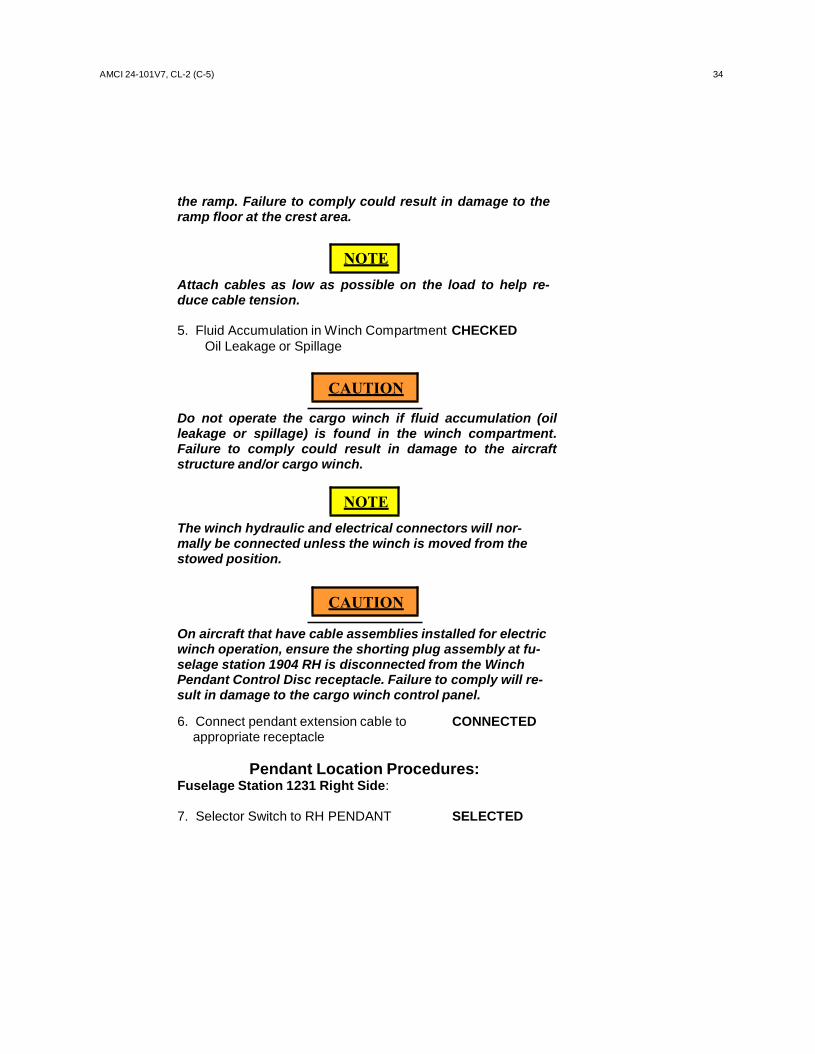
the ramp. Failure to comply could result in damage to the ramp floor at the crest area.
NOTE
Attach cables as low as possible on the load to help re- duce cable tension.
5. Fluid Accumulation in Winch Compartment CHECKED
Oil Leakage or Spillage
CAUTION
Do not operate the cargo winch if fluid accumulation (oil leakage or spillage) is found in the winch compartment. Failure to comply could result in damage to the aircraft structure and/or cargo winch.
NOTE
The winch hydraulic and electrical connectors will nor- mally be connected unless the winch is moved from the stowed position.
CAUTION
On aircraft that have cable assemblies installed for electric winch operation, ensure the shorting plug assembly at fu- selage station 1904 RH is disconnected from the Winch Pendant Control Disc receptacle. Failure to comply will re- sult in damage to the cargo winch control panel.
6. Connect pendant extension cable to CONNECTED
appropriate receptacle
Pendant Location Procedures: Fuselage Station 1231 Right Side:
7. Selector Switch to RH PENDANT SELECTED

35 AMCI 24-101V7, CL-2 (C-5)
8. Left Selector Switch to “FWD PENDANT” SELECTED On cargo winch remote control panel
9. Right Selector Switch to “FWD WINCH” / AS REQUIRED
“AFT WINCH”
Fuselage Station 1208 Left Side:
10. Selector Switch to “LH PENDANT” SELECTED
11. Left Selector Switch to “FWD PENDANT” SELECTED
12. Right Selector Switch to “FWD WINCH” / AS REQUIRED “AFT WINCH”
Fuselage Station 1904 Cargo Winch Remote Control Panel:
13. Selector Switch to “AFT PENDANT” SELECTED
14. Right Selector Switch to “FWD WINCH” / AS REQUIRED
“AFT WINCH”
15. Hydraulic Selector Valves CHECKED Fuselage Station 604 & 1620 Proper Positioning
16. No. 1 or No. 4 Hydraulic CHECKED /
System Pressurized AS REQUIRED
17. Direct Communication with ESTABLISHED Load Team
CAUTION
Initial reel-out of the cable shall be accomplished by a sharp pull to prevent cable entanglement.

AMCI 24-101V7, CL-2 (C-5) 36
CAUTION
Maintain tension on winch cable while reeling IN and OUT to prevent cable entanglement and snagging.
18. Load Team Member Maintain Tension BRIEFED / POSITIONED
19. Pendant POWER Switch to “ON” SELECTED
20. Pendant SPEED Switch to “HI” SELECTED
21. WINCH Thumbwheel Control OUT
Continue to move thumbwheel control Towards the OUT direction until no Further movement can be obtained
22. Cable Reel Out REQUIRED
LENGTH
NOTE
Complete reel out/inspection of the winch cable is required anytime maintenance is performed on the cable/winch, prior to winching operations, and when a pallet will cover the position.
23. Winch Cable INSPECTED
WARNING
An unserviceable winch cable can be a hazard to the load- ing crew during winch on/off loading operations. It could break under load and whiplash, resulting in serious injury to personnel and/or causing severe damage to the aircraft. Before any winching is accomplished, inspect the winch cable as described in step 4.14.4.k and step 4.14.4.l.
24. Hook and Cable Assembly INSPECTED Washer must be indented twice in the cable assembly notches and twice in the hook assembly notches (total of four indentations)

37 AMCI 24-101V7, CL-2 (C-5)
A. Spring and Clip CHECKED
B. Hook Rotates Freely CHECKED
C. Thrust Bearing INSTALLED
WARNING
Failure to ensure the thrust bearing is installed may cause the hook to separate from the winch cable, resulting in injury to loading personnel and/or damage to the airplane.
CAUTION
When snatch blocks are attached to the cargo floor, ensure shoring is placed between the snatch block hook and the tiedown ring pan receptacle. This will prevent damage to the tiedown ring pan receptacle during the winching opera- tions.
25. Install Snatch Block INSTALLED /
AS REQUIRED
26. Interphone Communication CHECKED / AS REQUIRED
NOTE
APEX personnel are expected to utilize interphone capability. This will be especially critical during APU operations. Aircraft interphone communications may be necessary when Maintenance supervisor is not in the cargo compartment. Ensure that communications are maintained at all times between all on/off loading personnel.
NOTE
Observers will be on interphone if the configuration or size of the cargo being winched prevents a clear view of all ob- servers by the winch operator, or if excessive noise pro- hibits verbal communication.

AMCI 24-101V7, CL-2 (C-5) 38
27. Cargo Compartment/Cargo CLEAR
NOTE
Ensure cargo floor is clear of obstructions and all person- nel not involved in winching are well clear. The winch op- erator will coordinate with the observers, ensure the cargo to be winched is clear, and determine it is safe to begin winching.
28. Spotters to Observe Critical Clearances BRIEFED / POSITIONED
29. Winch Cable to Bridle ATTACHED
NOTE
Slowly move thumbwheel towards the “IN” direction to take up cable slack.
30. WINCH Thumbwheel IN
Slowly move thumbwheel towards the IN direction to take up cable slack
CAUTION
Ensure output sheave on top of cargo winch is aligned with the direction of the cable pull. Failure to comply could cause a side load condition, resulting in damage to the cargo winch.
31. Security of Attachment Points CHECKED
and Cable Routing
NOTE
Brief the driver(s) to follow all signals and not to apply brakes while item is being winched.
32. Vehicle Driver BRIEFED /
AS REQUIRED
NOTE
Attach a steering yoke by looping strap(s) through the eye of the tow bar. The steering yoke should be long enough that personnel steering will not be directly behind or in front of the moving cargo. This method of steering is nor- mally used for trailers or ground support equipment.
33. Steering Yoke ATTACHED /
AS REQUIRED

39 AMCI 24-101V7, CL-2 (C-5)
WARNING
Closely observe load movement during winching opera- tion. If at any time load movement stops, reverses, or ca- ble jerking is experienced during winching, the control pendant thumbwheel shall be immediately released to the neutral position to ensure brake engagement. Failure to comply may result in damage to equipment or injury to personnel.
WARNING
If the winch motor stalls or the cable jerks; discontinue winching operations. Reduce the cable load prior to con- tinuing with winching operations.
NOTE
If reducing cable load, the cable pull must be recalculated.
NOTE
Fast speed loading can only be accomplished where cable pull will not exceed 2,000 pounds.
34. Pendant SPEED Switch HIGH OR LOW /
AS REQUIRED
35. WINCH Thumbwheel IN Slowly release and move thumbwheel control to “IN” direction
36. Restrain Cargo AS REQUIRED
37. Unhook Winch Cable from Bridle COMPLETE
38. Repeat Steps 28 through 38 AS REQUIRED
39. Remove Winch Cable from Snatch Blocks COMPLETE
40. Detach Snatch Blocks and Stow COMPLETE

AMCI 24-101V7, CL-2 (C-5) 40
NOTE
During off loading, before the load goes over the ramp crest, ensure that all cable slack is removed. Rewind the cable until tension is evident.
41. Offloading COMPLETED
CAUTION
Maintain tension on winch cable while reeling in and out to prevent cable entanglement and snagging.
NOTE
The winch will automatically stop when all of the cable is reeled in except for the length necessary to stow the cable hook.
42. Pendant Speed HIGH
43. Winch Thumbwheel IN
Slowly release and move thumbwheel control to “IN” direction
44. Pendant Power OFF
45. Hydraulic System OFF /
AS REQUIRED
46. Pendant Extension Cable DISCONNECT / Disconnect and stow pendant and IF USED cable at fuselage station 1208
47. Output Sheave and Hatch STOWED / INSTALLED
48. AFT WINCH COMPT HATCH Light CHECKED
OFF
41 AMCI 24-101V7, CL-2 (C-5)
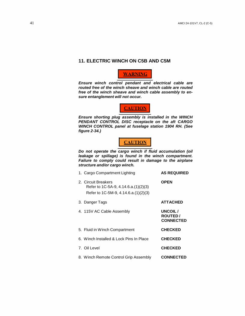
11. ELECTRIC WINCH ON C5B AND C5M
WARNING
Ensure winch control pendant and electrical cable are routed free of the winch sheave and winch cable are routed free of the winch sheave and winch cable assembly to en- sure entanglement will not occur.
CAUTION
Ensure shorting plug assembly is installed in the WINCH PENDANT CONTROL DISC receptacle on the aft CARGO WINCH CONTROL panel at fuselage station 1904 RH. (See figure 2-34.)
CAUTION
Do not operate the cargo winch if fluid accumulation (oil leakage or spillage) is found in the winch compartment. Failure to comply could result in damage to the airplane structure and/or cargo winch.
1. Cargo Compartment Lighting AS REQUIRED
2. Circuit Breakers OPEN
Refer to 1C-5A-9, 4.14.6.a.(1)(2)(3) Refer to 1C-5M-9, 4.14.6.a.(1)(2)(3)
3. Danger Tags ATTACHED
4. 115V AC Cable Assembly UNCOIL /
ROUTED / CONNECTED
5. Fluid in Winch Compartment CHECKED
6. Winch Installed & Lock Pins In Place CHECKED
7. Oil Level CHECKED
8. Winch Remote Control Grip Assembly CONNECTED

AMCI 24-101V7, CL-2 (C-5) 42
9. Cable Assembly CONNECTED
10. Winch Power CHECKED
11. Circuit Breakers CLOSED Refer to 1C-5A-9, 4.14.6.h.(1)(2)(3) Refer to 1C-5M-9, 4.14.6.h.(1)(2)(3)
12. Danger Tags REMOVED
13. Direct Communication with Load ESTABLISHED Team Members
WARNING
Ensure winch control pendant and electrical cable are routed free of the winch sheave and winch cable assembly to ensure entanglement will not occur.
CAUTION
Maintain tension on winch cable while reeling in and out to prevent cable entanglement and snagging.
14. Winch Cable Taut CHECKED
15. Place MODE switch to FAST SELECTED
16. Place SELECT switch to UNWIND SELECTED
17. Appropriate Length of Cable Released CHECKED
WARNING
An unserviceable winch cable can be a hazard to the load- ing crew during winch on/off loading operations. It could break under load and whiplash resulting in serious injury to personnel and/or causing severe damage to the airplane structure. Before any winching is accomplished, inspect the cable.
18. Winch Cable INSPECTED
43 AMCI 24-101V7, CL-2 (C-5)
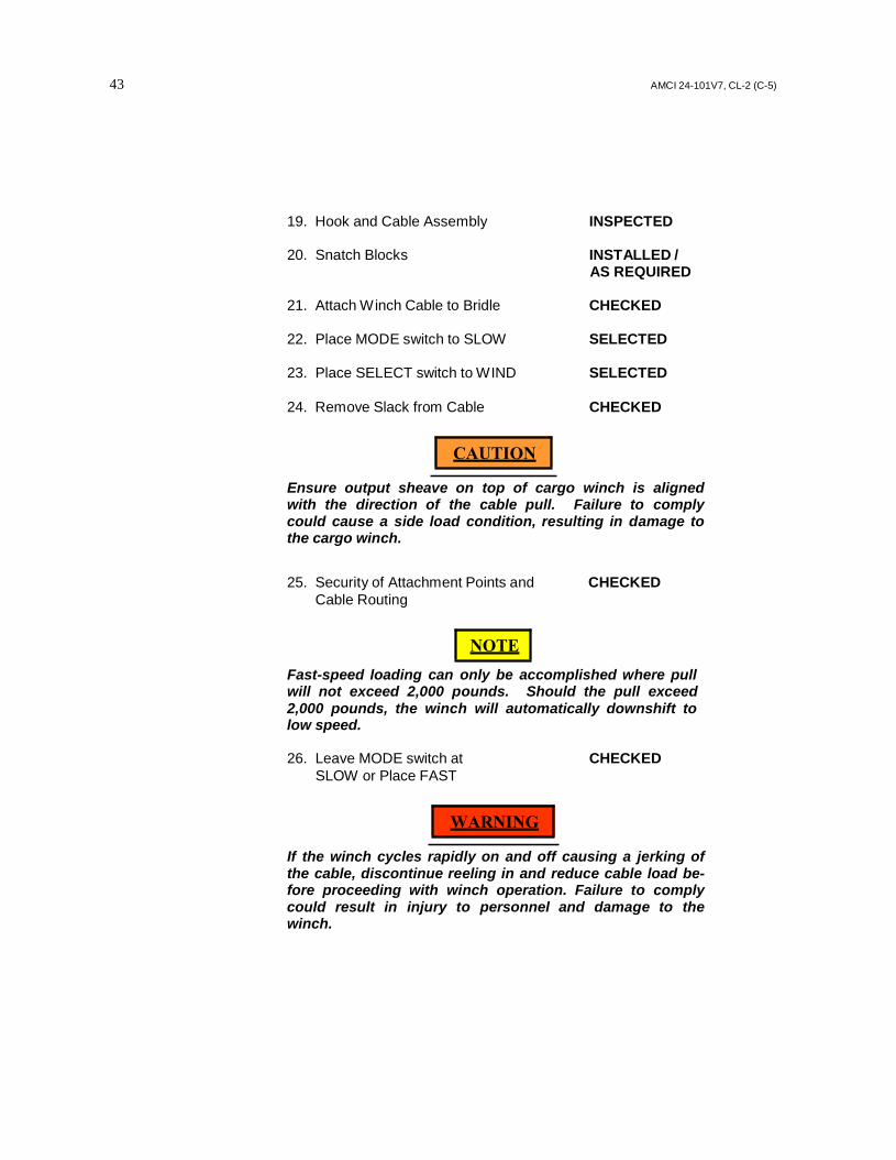
19. Hook and Cable Assembly INSPECTED
20. Snatch Blocks INSTALLED / AS REQUIRED
21. Attach Winch Cable to Bridle CHECKED
22. Place MODE switch to SLOW SELECTED
23. Place SELECT switch to WIND SELECTED
24. Remove Slack from Cable CHECKED
CAUTION
Ensure output sheave on top of cargo winch is aligned with the direction of the cable pull. Failure to comply could cause a side load condition, resulting in damage to the cargo winch.
25. Security of Attachment Points and CHECKED Cable Routing
NOTE
Fast-speed loading can only be accomplished where pull will not exceed 2,000 pounds. Should the pull exceed 2,000 pounds, the winch will automatically downshift to low speed.
26. Leave MODE switch at CHECKED
SLOW or Place FAST
WARNING
If the winch cycles rapidly on and off causing a jerking of the cable, discontinue reeling in and reduce cable load be- fore proceeding with winch operation. Failure to comply could result in injury to personnel and damage to the winch.

AMCI 24-101V7, CL-2 (C-5) 44
NOTE
If reducing cable load, the cable pull must be recalculated.
27. Position Cargo CHECKED
28. Restrain Cargo AS NEEDED
29. Unhook Winch Cable from Bridle CHECKED
30. Snatch Blocks STOWED
CAUTION
Maintain tension on winch cable while reeling in and out to prevent cable entanglement and snagging. 31. Place MODE switch to FAST SELECTED
32. Place SELECT switch to WIND SELECTED
Squeeze and hold trigger switch until all of the winch cable is reeled in, then release the switch.
33. Place SELECT switch to OFF SELECTED
34. Circuit Breakers OPEN
Refer to 1C-5A-9, 4.14.6.af.(1)(2)(3) Refer to 1C-5M-9, 4.14.6.h.(1)(2)(3)
35. Danger Tags ATTACHED
36. Cable Assembly DISCONNECTED
37. Winch Remote Control Grip Assembly DISCONNECTED /
STOWED
CAUTION
Ensure that the winch AC and DC electrical cables are dis- connected, coiled, and stowed before securing the winch compartment access hatch.

45 AMCI 24-101V7, CL-2 (C-5)
38. AC & DC Cable Assemblies DISCONNECTED / COIL / STOW
39. Circuit Breakers CLOSED
Refer to 1C-5A-9, 4.14.6.aj.(1)(2)(3) Refer to 1C-5M-9, 4.14.6.h.(1)(2)(3)
40. Danger Tags REMOVED
41. Output Sheave and Hatch STOWED /
INSTALLED
42. Aft Winch Compartment Hatch Light OFF

AMCI24-101V 7CL-2 46
12. AFTER LOADING CHECKLIST
1. Cargo Winch STOWED
2. Cargo Doors and Ramps CLOSED / Coordinate with maintenance AS REQUIRED
3. Cargo Restraint CHECKED
4. Loose Equipment SECURED
NOTE
Check for fumes, leaks, placement of cargo, and location of special handling cargo
5. Tie down Equipment Inventory ASSIGNED
6. Cargo Compartment Vents CLOSED /
AS REQUIRED
7. General Cleanliness CHECKED
8. Curb Lights OFF
9. Parking Brake OFF Coordinated with maintenance
AMCI24-101V7CL2 47
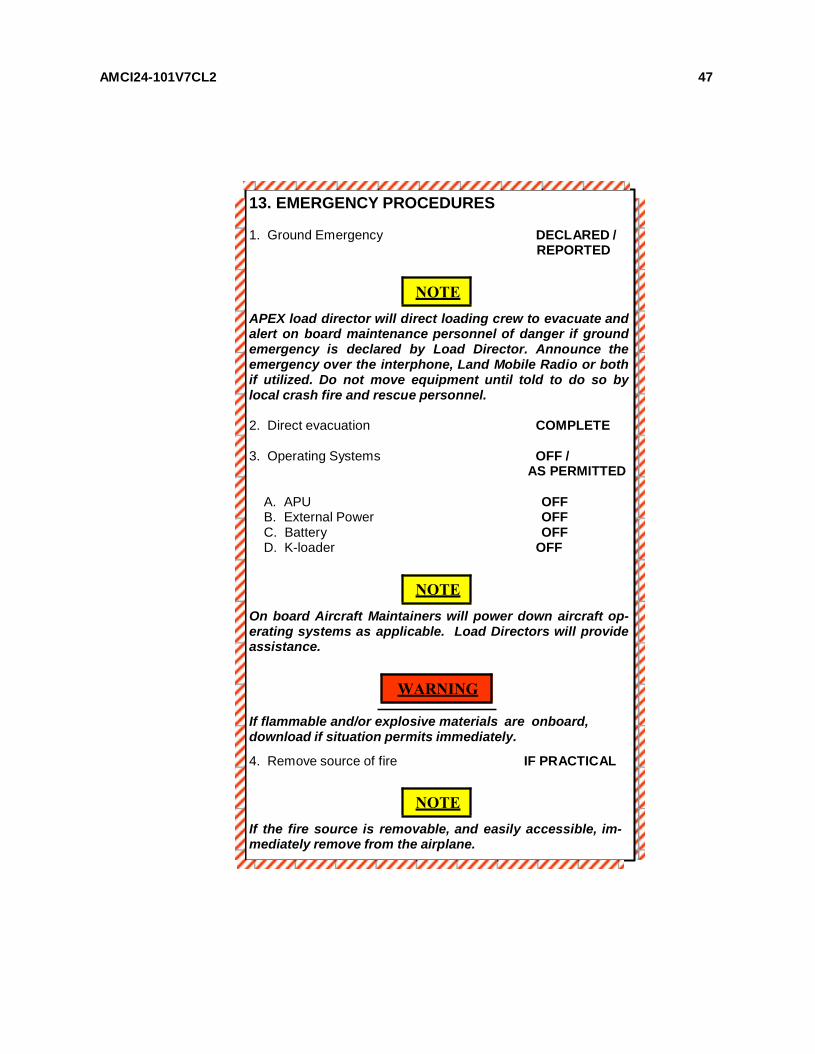
13. EMERGENCY PROCEDURES
1. Ground Emergency DECLARED / REPORTED
NOTE
APEX load director will direct loading crew to evacuate and alert on board maintenance personnel of danger if ground emergency is declared by Load Director. Announce the emergency over the interphone, Land Mobile Radio or both if utilized. Do not move equipment until told to do so by local crash fire and rescue personnel.
2. Direct evacuation COMPLETE
3. Operating Systems OFF /
AS PERMITTED
A. APU OFF B. External Power OFF C. Battery OFF D. K-loader OFF
NOTE
On board Aircraft Maintainers will power down aircraft op- erating systems as applicable. Load Directors will provide assistance.
WARNING
If flammable and/or explosive materials are onboard, download if situation permits immediately.
4. Remove source of fire IF PRACTICAL
NOTE
If the fire source is removable, and easily accessible, im- mediately remove from the airplane.

AMCI 24-101V7, CL-2 (C-5)
5. Extinguish fire IF PRACTICAL
6. Close Oxygen Manual Shutoff Valve COMPLETED / and evacuate (FS 1465) AS PRACTICAL
7. Account for personnel CHECKED /
COMPLETED