by paul richard and jim fitzgerald chapter 18 – drawing management tools and utilities
TRANSCRIPT

by Paul Richard and Jim Fitzgerald
Chapter 18 – Drawing Management Tools and Utilities

• Understand the backup and autosave settings• Fix a corrupt drawing• Purge a drawing of unused data• Import and export different drawing file types• Copy and paste information between different software applications• Use object linking and embedding objects in AutoCAD drawings• Automate repetitive tasks using the Action Recorder• Use the Measure tools• Use the QuickCalc calculator• Delete duplicate objects• Use web-based collaboration tools

The File Safety Precautions area of the Open and Save tab on the Options dialog box allows you to control some of these backup and file recovery options.

Backup files (BAK) are created only when you save your drawing. For this reason, it’s considered good practice to save your drawing often. However, there are times when AutoCAD quits before you have the opportunity to save. To help recover from these instances, AutoCAD can automatically save your drawing file at regular intervals. This is known as an autosave. By default, AutoCAD does this every 10 minutes.
Automatic save to C:\Users\Paul\appdata\local\temp\AS-01_1_1_7542.sv$
AutoCAD displays a message when it is performing an automatic save while you are working. Following is an example:
If you do not see a message from AutoCAD, you should check that the Autosave feature is enabled and that a reasonable save interval is set.

Temporary Drawing File Location setting in the Files tab on the Options dialog box allows you to change the location where these temporary files are stored

Richard / Fitzgerald :INTRODUCTION TO AutoCAD 2012 Copyright 2012 Pearson Education, Upper Saddle River, NJ 07458. All Rights Reserved
The Drawing Recovery Manager provides an easy way to examine backup and autosave files
NOTEAlthough these tools can recover many damaged or corrupt drawings, they are not guaranteed to recover all lost information. Remember to save often and back up critical drawing files on a regular basis.
NOTEAlthough these tools can recover many damaged or corrupt drawings, they are not guaranteed to recover all lost information. Remember to save often and back up critical drawing files on a regular basis.

AutoCAD provides two commands to examine and repair these files: AUDIT and RECOVER.
The RECOVER command allows you to select any drawing file to scan. The AUDIT command scans only the currently open drawing file. In addition, the AUDIT command gives you the option of just scanning the file without attempting to correct the problems.

Layer settings, block definitions, linetypes, text styles, plot styles, table styles, dimension styles, and other nongraphical elements can be stored in a drawing, even if they may not be used within the drawing. It is possible to have empty layers, unused linetypes, dimension styles, etc.

When you start the PURGE command, AutoCAD displays the Purgedialog box. This dialog box has a list of the various items that can be purged from a drawing.

AutoCAD has the ability to read and write a number of different raster and vector file formats.
The EXPORT command allows you to export AutoCAD drawing information to various file formats.
The IMPORT command allows you to convert various file formats to AutoCAD objects

The table describes the various file formats that AutoCAD supports and the commands that are available to read or write.

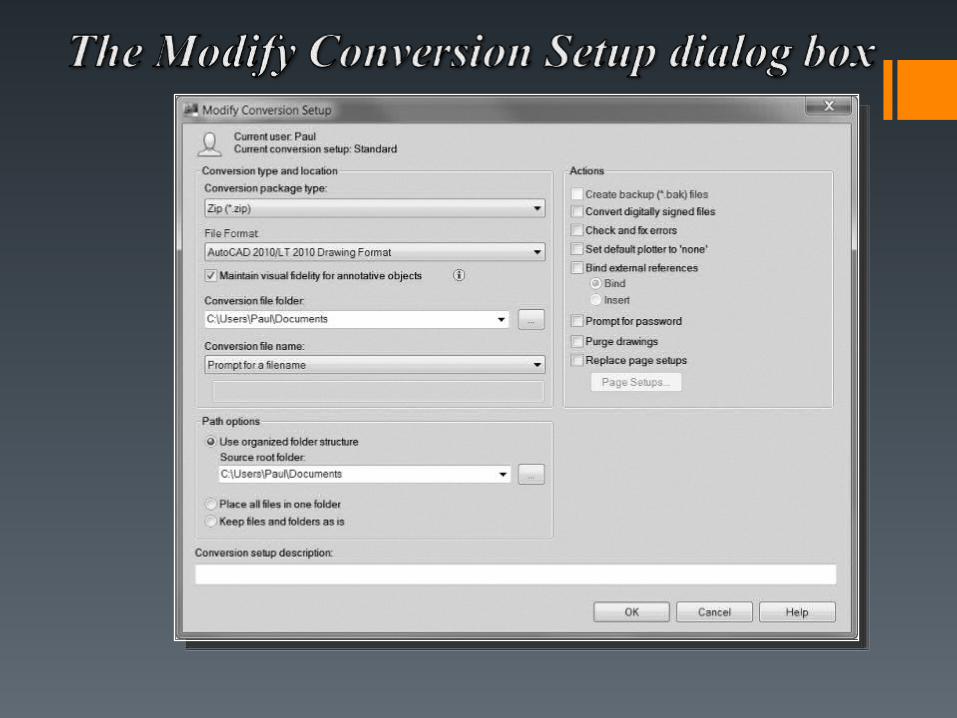
The DWG Convert tool allows you to convert a group of drawings to the following AutoCAD DWG release formats: AutoCAD 2010, AutoCAD 2007, AutoCAD 2004, AutoCAD 2000, and AutoCAD R14.

Object Linking and Embedding (OLE) allows you to share information between two windows applications.
An example would be if you were to embed an AutoCAD drawing in a Word document. AutoCAD is the source, and Word is the destination.
NOTEAlthough the Windows OLE feature can use AutoCAD as either a source or a destination application, this chapter focuses primarily on placing OLE objects in AutoCAD drawings. Keep in mind that the behavior of data from other applications will vary from programto program. To link or embed AutoCAD drawings in other applications, refer to the documentation for that application for specifics on using OLE within that program.
NOTEAlthough the Windows OLE feature can use AutoCAD as either a source or a destination application, this chapter focuses primarily on placing OLE objects in AutoCAD drawings. Keep in mind that the behavior of data from other applications will vary from programto program. To link or embed AutoCAD drawings in other applications, refer to the documentation for that application for specifics on using OLE within that program.
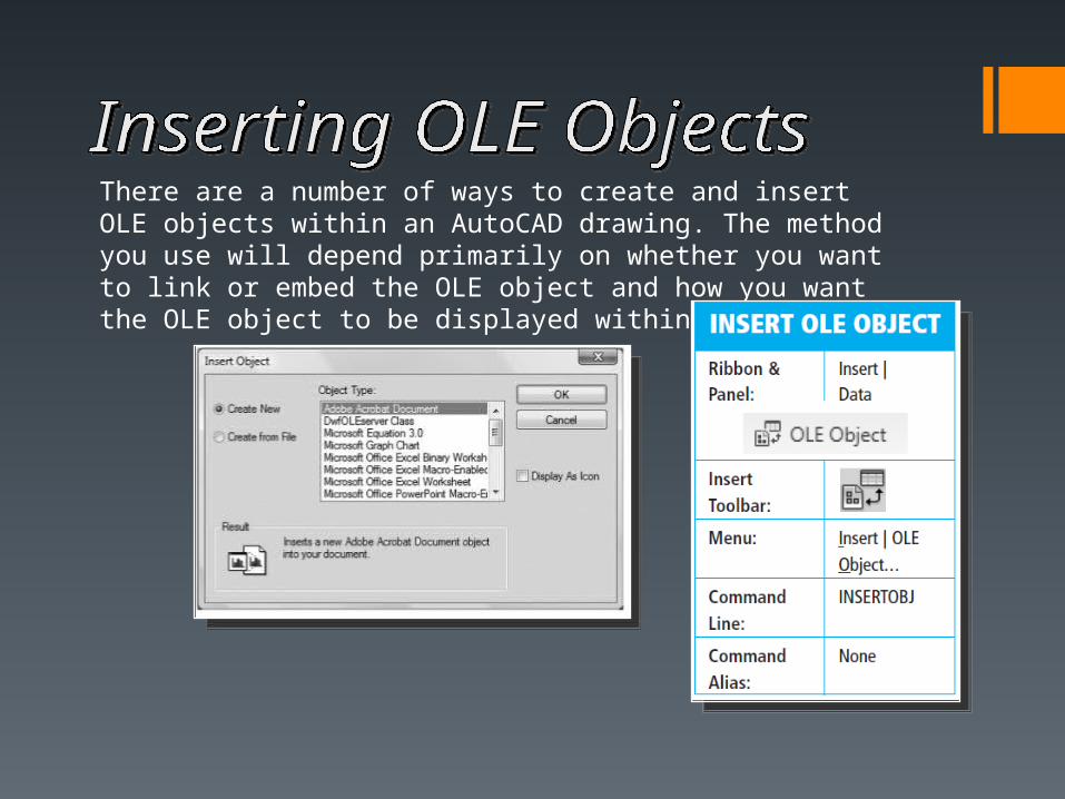
There are a number of ways to create and insert OLE objects within an AutoCAD drawing. The method you use will depend primarily on whether you want to link or embed the OLE object and how you want the OLE object to be displayed within the drawing.

The Windows Clipboard feature can also be used to link and embed data from other applications. The Windows Clipboardprovides a way to store data temporarily from most Windows programs. In most Windows applications, you can select data and choose Copy from the Edit pull-down menu or press <Ctrl>C within that application. Once information is copied to the Windows Clipboard, it can be pasted into other locations within the same program or into other Windows applications.

The PASTECLIP command will place the contents of the Clipboard as an embedded OLE object. When you start the PASTECLIP command, AutoCAD will prompt you for an insertion point. Depending on the type of data in the Clipboard, AutoCAD may display the OLE Text Size dialog box.

Double-clicking an OLE object will launch the source application with the OLE data.

The Action Recorder tool allows you to automate repetitive tasks by recording the AutoCAD commands, inputs, and options you enter as an Action Macro that you, or anyone else, can replay later.
NOTEThere are certain actions that cannot be recorded—specifically, file operation commands such as OPEN and CLOSE, as well as any type of grip editing. Although it is possible to display a dialog box, it is not possible to track and record your actions once it is displayed.Additionally, the Quick Properties palette is not recognized and certain tool palette commands cannot be recorded.
NOTEThere are certain actions that cannot be recorded—specifically, file operation commands such as OPEN and CLOSE, as well as any type of grip editing. Although it is possible to display a dialog box, it is not possible to track and record your actions once it is displayed.Additionally, the Quick Properties palette is not recognized and certain tool palette commands cannot be recorded.

All the actions entered are saved to an Action Macro file with an .ACTM file extension
With Action Macros you can go back and customize the recording list by adding your own text messages and requests for user input by right-clicking on an action in the Action Tree window and using the shortcut menu

The best thing about action macros is that, after you are done recordinga macro, you can go back and customize it by adding your own text messagesand pauses for user input by right-clicking on an action in the Action Treewindow and using the shortcut menu
NOTEThere are a few limitations when naming an action macro. An action macro cannot have the same name as an AutoCAD command. For instance, you cannot create a macro named LINE. It is also not possible to use spaces or special characters. It is suggested you substitute a dash (-) or an underscore (_) when a space is required.
NOTEThere are a few limitations when naming an action macro. An action macro cannot have the same name as an AutoCAD command. For instance, you cannot create a macro named LINE. It is also not possible to use spaces or special characters. It is suggested you substitute a dash (-) or an underscore (_) when a space is required.

The QuickCalc calculator provides all of the functionality of a traditional desktop calculator, or even the Windows calculator, plus a host of unique features that are specific to AutoCAD.
The QuickCalc toolbar buttons
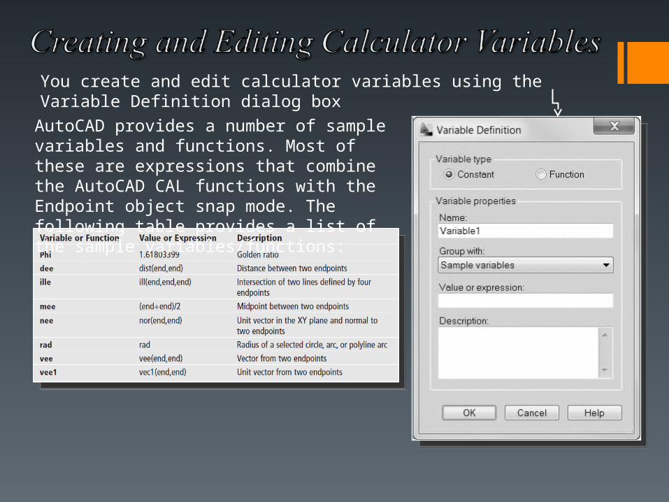
You create and edit calculator variables using the Variable Definition dialog box
AutoCAD provides a number of sample variables and functions. Most of these are expressions that combine the AutoCAD CAL functions with the Endpoint object snap mode. The following table provides a list of the sample variables/functions:

The Delete Duplicate Objects tool helps you clean up your drawings by removing duplicate or unnecessary drawing objects (lines, arcs, polylines) so that you can enhance and preserve the data integrity of your drawings.

AutoCAD is integrated directly with the Internet and the AutoCAD WS weband mobile applications. AutoCAD WS lets you view, edit, and share drawingsusing the web or a mobile device. The AutoCAD WS tools are locatedon the Online tab of the ribbon
• Uploading Drawings
• Working Online
• Collaborating

• Uploading Drawings
The Upload tool allows you to upload the current drawing to a secure location on the AutoCAD WS server. Once you log in to AutoCAD WS, you can set the Upload tool to upload automatically.
The AutoCAD WS tools are located on the Online tab of the ribbon
• Working Online
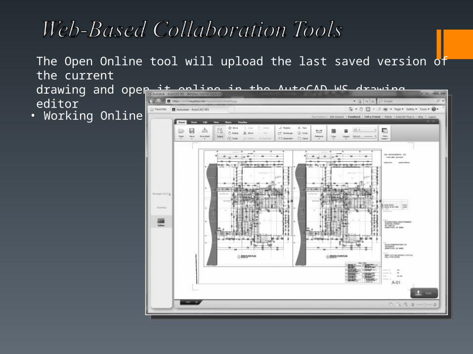
The Open Online tool will upload the last saved version of the currentdrawing and open it online in the AutoCAD WS drawing editor

• Collaborating
The Share Drawing tool allows you to send an email to one or more people with whom you want to share your current drawing and select whether to limit access to viewing, editing online, or download only.