by paul sedlet and nick terry, accurate corrosion control...
TRANSCRIPT

By Paul Sedlet and Nick Terry, Accurate Corrosion Control, Inc.
August 28, 2018
Accurate Corrosion Control, Inc.

Accurate Corrosion Control, Inc.

▪ This presentation will discuss ways to measure the most accurate “polarized” potential.
▪ The first portion of this presentation is about using interruption to consider IR in pipe-to-soil potentials. The second part discusses alternative methods when you can’t interrupt all current sources.
▪ To effectively measure the polarized potential, it is necessary to eliminate or reduce errors in the measurement, such as:
▪ Soil IR (ionic voltage drop due to current flow)
▪ Metal IR (metallic voltage drop due to current flow)
Accurate Corrosion Control, Inc.

▪Polarize a structure to a potential that is equal to, or more negative than it’s most active anode Richard Patterson
▪Cathodic protection is complete when the corrosion cell cathodes are polarized electro-negatively to the open circuit potential of the most electronegative anode site on the structure
R. B. Mears and R. H. Brown, A theory of cathodic protection, Trans. Electrochem. Soc. 74, 519 (1938)
Accurate Corrosion Control, Inc.

▪ NACE Standard Practice SP0169-2013:
▪ Criteria for Cathodically Protected Structures in Electrolyte
▪ “A negative potential of at least 850 mV….with respect to copper/copper sulfate reference electrode…..VOLTAGE DROP (IR)…must be considered for valid interpretation of this voltage measurement.”
▪ “A minimum of 100 mV of cathodic polarization between the structure surface and a stable reference electrode contacting the electrolyte. The formation or decay of polarization can be measured.”
▪ NACE Test Method TM-497
▪ Describes consideration of voltage drops other than across the structure to electrolyte boundary. Use of coupons to consider soil IR, discusses metal IR and polarization curves.
Accurate Corrosion Control, Inc.

• -850mV “ON” • With CP applied
▪ Knowing which CP systems have influence on this number is helpful
• -850mV “IRF” ▪ Synchronous current
interruption is generally required
▪ Knowing and understanding which CP Systems and current sources have an influence on this number is necessary
• 100mV Polarization

Ref Cell
Voltmeter
Test Wire
Test
Station
Ref to Soil
Interface
Soil to Pipe InterfaceMetal IR
Soil IR
Mixed
Potential

▪ Current interrupters:
▪ Benefits: Synchronized CP Current interruption to provide instant off potentials reducing effects of soil and metal IR
Accurate Corrosion Control, Inc.

▪Metal IR is the error that occurs in the pipe-to-electrolyte measurement due to current flow in the pipeline or in a cable.
▪Metal IR can be measured between test points as the voltage drop between the test points and relates approximately to near ground (NG) and far ground (FG) potentials.
▪Metal IR error can either add or subtract from the actual potential, depending upon the resultant current flow between test points

Accurate Corrosion Control, Inc.

▪If conducting a CIS on a 2” diameter gas line, with a rectifier, output 10 amps, what is the possible metal IR influence?
▪2” pipe is 79.2 micro-ohms per foot. At the end of a 1000 foot run going towards or away from the rectifier, then:

▪.0000792 x 1000 = .0792 ohms x 10 amps = .792 volts or 792 mV.
▪This means that your “On” P/S could be off by nearly 800mV in this example!

Note the
polarization
characteristic
in the All Off
Cycle

Well coated line bored under
poorly coating line. Soil IR
from foreign line is a large
component of the surface P/S
Reference cell at
surface
Soil tube

Note the de-
polarization
characteristic
in the All Off
Cycle
When a soil tube
was installed the
“On” potential was
-1100mV

-725mV On Potential
-1100 mV
Polarized
Potential
Note depolarization in All
off cycle

Accurate Corrosion Control, Inc.
-1070mV Polarized Potential
and relatively rapid
depolarization
Bond exchanging 6.5A from ELMO to
GROVER pipeline
-1640mV On Potential

Accurate Corrosion Control, Inc.
-1168 mV Polarized
Potential
-720mV On Potential
More polarization is
being achieved with
the bond out even
though the “On”
potential is more
positive

Accurate Corrosion Control, Inc.
Note no
depolarization
at the instant off

▪ Soil Tubes-
▪ Coupon Test Stations-
Accurate Corrosion Control, Inc.

▪ Soil Access Tubes
▪ Benefits: Reference Cell potentials near the surface of the structure reducing effects of soil IR
Accurate Corrosion Control, Inc.
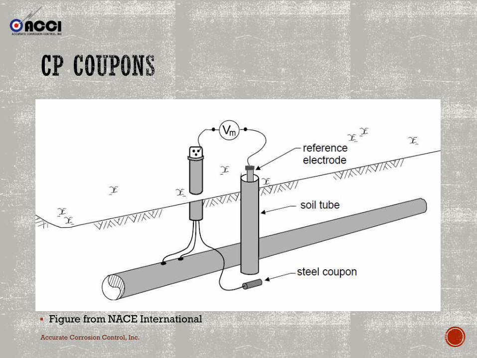
▪ Figure from NACE International

▪ Corrosion Coupons:
▪ NACE Standard Practice SP0104-2014:
▪ Title: The Use of Coupons for Cathodic Protection Monitoring
Applications
▪ Outlines the use of coupons as a means to consider IR drop in potential
measurements when determining the level of CP.
▪ NACE Test Method TM0497-2012: Appendix C
▪ Title: Measurement Techniques Related to Criteria for CP on
Underground or Submerged Metallic Piping Systems
▪ Using Coupons to Determine Adequacy of Cathodic Protection
Accurate Corrosion Control, Inc.

▪ Use of Coupons at Test Stations
▪ Benefits: Simulated coating
deficiency under known conditions
with breakable bond to the CP
system to provide instant off
potentials reducing effects of metal
IR. If coupled with a soil access tube,
reduction to soil IR can also be
achieved.
Accurate Corrosion Control, Inc.

▪ Test Method – 0497-2012L Appendix C
▪ Selected Test Site Considerations:
▪ Nominally of the same material and surface condition of structure
▪ Small enough to avoid excessive current drain for the CP System
▪ Placed at pipe depth in the same backfill
▪ Surface prepared with all mill scale & foreign materials removed
▪ Placed at a know location of suspected coating defect
▪ Bonded to CP System through test leads brought up above surface
Accurate Corrosion Control, Inc.
Accurate Corrosion Control, Inc.
▪ Figure from NACE International

▪ Coupons Test Stations
▪ Widely Commercially available for install.
▪ Two Types:
▪ Integrated Coupon Test Station
▪ Coupon(s) mounted at the end of PVC soil tube and wired to a switch or bus bar to trigger instant off potential readings.
▪ Vertical IR Drop Coupon Test Station
▪ Coupon embedded into the face of test station with vertical porous plug slot centered in the coupon. With this configuration, no IR drop exist between the reference and coupon and therefore no disconnect is necessary.
Accurate Corrosion Control, Inc.
Accurate Corrosion Control, Inc.
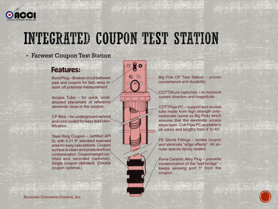
▪ Farwest Coupon Test Station

Accurate Corrosion Control, Inc.
▪ American Innovations Fink ▪ ACCI ALL In One Test Box

Accurate Corrosion Control, Inc.

▪ If you are not interrupting all current sources you may not be measuring an accurate polarized potential. Polarization is the achievement of cathodic protection.
▪ Most Operators only interrupt their own rectifiers while performing annual surveys and while conducting Close Interval Surveys. Foreign soil IR may be influencing in this situation.
▪ When performing interference testing, all influencing current sources should be included in the testing to measure the “polarized” potential. A suppression caused from a foreign operator is not necessarily interference. The “On” potential may just be influenced by soil gradient. All “IR” should be considered.
▪ Soil tubes and coupons are a great alternative to consider IR in pipe-to-soil potentials when not all current sources can be interrupted.
Accurate Corrosion Control, Inc.