byco: an overwhelming learning experience · 9 | p a g e. orc - i. cdu . crude distillation unit....
TRANSCRIPT
Byco: An Overwhelming Learning Experience
(A more like compte rendu of internship)
June – July 2016
At ORC - I
Syed Ahsan Imam
Compiled as an Engineering Intern
Under Operations/OMS at Byco Petroleum
Belongs to Penultimate Year under B.E. in
Department of Chemical Engineering
NED University of Engineering & Technology
1 all information cited here or whatever are as of July, 2016.
Prologue
This report has been written with an intention to share my personal experience at Byco Petroleum
Pakistan Limited as an engineering intern and to give exposure to the future interns as well as any
individual who wants to know about it. Thus, I personally want to call it a review based write-up report.
If anyone wants to know about the corporate profile, then the official website describes at its best that’s
why I have not discussed about it separately. Similarly, being a forward vertically integrated company;
knowledge about the organization, marketing and the other end-to-end business can also be dug online.
As a Chemical & Process Engineering student, I have merely focused on the process and operations side
during the internship period, covering all the possible downstream section. Though, I have also shared
some words about the safety regulations and compliances as well as laboratory testing methodology
being used at Byco. Thus, this report mainly incorporates major part of the above said discipline.
My location was at ORC-1 under Operations/OMS. The environment of safety over there is really sound
which shows they are maintaining the safety compliances to the defined level. Tons of things available
to learn over there which all cannot be fully understand during the limited internship period but I would
like to advice the readers, whether one have studied the concerned subjects or not; try to gain some
pre-requisite knowledge about the process as it would surely be fruitful for the future interns. I hope the
readers can find this small contribution helpful in knowing the dynamics of the process side of the plant.
Acknowledgement
The Byco corporate office and HR department deserve the word of appraisal for providing the chance to
the novice undergraduates to get the real-time exposure of industry and an unforgettable learning
experience, also should be given huge applause for reaching the university and hiring the students as an
intern as well as to the Directorate of Industrial Liaison, NED-UET for the timely management and
support to the students. Every individual, from technicians to engineers, whoever played a role in my
learning experience earns bunch of applause. I would also like to thank the non-technical staff of the
admin office for the courage and support they have showed. Handling interns is not an easy task, the
time it consumes of Shift Engineers costs much but they have provided us the maximum possible period
for briefing about the plant while maintaining their own working responsibilities and for me, this is what
actually matters in creating a foreground image of a company. Thanks a million, Byco!
Dated: 14th July 2016

Table of Contents
General Overview ................................................................................................................................... 8
Process Section at ORC – I ............................................................................................................... 10
Crude Distillation Unit (CDU)............................................................................................................ 10
Pre – Treatment of Crude ....................................................................................................................... 10
Something about the desalter ............................................................................................................. 11
What’re the important parameters to consider in desalter? .............................................................. 11
*Boot Water: An important overhead component ............................................................................ 12
1Crude Tower Overhead Corrosion Problem, how can it be prevented? ............................................. 12
How Byco is taking Prevention Measures? ......................................................................................... 13
Separation Process from Pre – Flash ...................................................................................................... 13
Why Pre – Flash? ................................................................................................................................. 14
Additives Used in Pre – Flash .............................................................................................................. 14
Heating Section ....................................................................................................................................... 16
Crude Tower or Distillation Column........................................................................................................ 16
What are the main obtained products? .............................................................................................. 17
A look on the distillation column ......................................................................................................... 17
5What’s the purpose of injecting steam? What kind of refinery is this? ............................................. 18
Main Refinery Types ............................................................................................................................ 18
4What does reflux system do? 6What are pump arounds? ................................................................. 19
Pump Around: Point to be noted ......................................................................................................... 20
2Knock-Out Drums: purpose? .............................................................................................................. 20
3Flare System: Purpose? ...................................................................................................................... 20
Stripping Section ..................................................................................................................................... 21
JP-I: Jet Fuel Production ...................................................................................................................... 21
Static Charge build up in JP – I: Hazard! ............................................................................................. 21
Accumulator ............................................................................................................................................ 22
Naphtha Splitter ...................................................................................................................................... 22
Why *fin fan is placed before **trim cooler when cooling down the product? ................................. 23
Additives Used in Heavy Bottoms ....................................................................................................... 23
MerOx Unit ..................................................................................................................................... 24
Why Sulphur/Mercaptan is injurious? ................................................................................................ 24

What is happening in MerOx unit? ..................................................................................................... 24
MerOx System at Byco ............................................................................................................................ 25
Why Use Caustic Pre-Wash? ............................................................................................................... 26
Spent Caustic Handling by Partial Oxidation of Sulfidic Caustic ......................................................... 27
Caustic Recirculation & Re-generation ............................................................................................... 27
Doctor Sweetening Process/Test ......................................................................................................... 31
Test for Sweetened Product ................................................................................................................ 32
Naphtha Hydro Treater Unit (NHT) .................................................................................................... 32
Main Reactions ....................................................................................................................................... 33
Main Process ........................................................................................................................................... 33
What’s RON & RVP? ............................................................................................................................ 33
Reformer Section ................................................................................................................................. 35
Main Process ........................................................................................................................................... 35
Where the Hydrogen comes for NHT? ................................................................................................ 35
Chemical Additives Used ..................................................................................................................... 35
Main Reactions ....................................................................................................................................... 36
What does SOR & EOR mean? ............................................................................................................ 37
Why the series of reactor is smaller at feed but larger on the product side? ..................................... 38
Some additional details about Reformer ............................................................................................ 38
Nature of Catalysts ............................................................................................................................. 40
Reactor Pressure and Temperature .................................................................................................... 40
LPG Separation Unit (LSU) ................................................................................................................... 42
Main Process ........................................................................................................................................... 42
(OMS) Oil Movement & Storage alias Tank Farm ....................................................................... 44
Fixed Roof Internal Floating Disc ........................................................................................................ 44
External Floating Roof ......................................................................................................................... 44
Piping System & Safety ....................................................................................................................... 44
Level Measuring .................................................................................................................................. 45
LPG Bullets .......................................................................................................................................... 45
Utilities Section .................................................................................................................................. 46
Boiler Operation .................................................................................................................................. 46
How can we recognize a water-tube boiler? ...................................................................................... 46
Types of Blowdown and how can scaling be prevented? ................................................................... 46

*Corrosion Issue: Prevention method ................................................................................................ 46
ORC – II, RO Plant Operation & Water Treatment ........................................................................... 47
Sea – Water Reverse Osmosis (SWRO) ............................................................................................... 47
Energy Recovery Turbine: recovery of energy from water ................................................................. 47
Brackish Water Reverse Osmosis (BWRO) .......................................................................................... 47
Electro Deionizer (EDI) ........................................................................................................................ 47

Process Diagrams, Tables & Equipment Lists Quick Guide
Reference Diagrams taken from various sources: Basic Furnace Operation on Page: 15 | Valve Tray Operation on Page: 16
Flare System: brief schematic like the one at Byco but details may vary on Page: 19
Kerosene and Naphtha MerOx: simplified process from UoP® but details may vary on Page 24
LPG MerOx, Caustic Recovery Unit, Spent Caustic System, Combination System: simplified process,
(please be noted that the recovery unit is separately identified at Byco) on Page 25 & Page: 26
Reformer Unit Schematic on Page 31 | UOP® SR and CCR Reactor figures on Page: 37 & Page: 38
Rough description on how Reformer works on Page: 39
Reaction Sets and Tables: MerOx Reaction Table on Page: 23 | Doctor Sweetening Reaction Set on Page: 30-31
Reformer Reaction Set with Reactions on Active Sites & Symbol Key to Reaction Set on Page: 35 & 36
Tray Comparison Table on Page: 17
Simplified, self-traced and developed diagrams using MS Visio:
Pumping, pre-treatment, pre-flash, distillation, side strippers process flow diagram on page: 14
Naphtha Splitter diagram on Page: 22
Light Naphtha & LPG MerOx process flow diagram on Page: 27 & 28
Kerosene and Heavy Naphtha MerOx process flow diagram on Page: 29
Caustic Regeneration System on Page: 30
Naphtha Hydro Treater Unit simplified process flow diagram on Page: 33
Reformer process flow diagram on Page: 40 | LPG Separation Unit (LSU) on Page: 42
Equipment Lists – Guide to PFDs: Crude Handling, Pre-treatment, Pre-flash, distillation, and furnace operations on Page: 13
Light Naphtha & LPG MerOx on Page: 27 & 28 | Kerosene and Light Naphtha MerOx on Page: 29
Naphtha Hydrotreater on Page: 33 | Reformer Unit on Page: 40 | LPG Separation Unit on Page: 42

First compiled, revised and presented to Advisory and HR Department of Byco Petroleum in July 2016
Second Revision and compilation was done in December 2016
Third Revision and compilation was done in May 2017
© All symbols, diagrams, names mentioned here are for reference and educational purpose only. Please be noted
that, the mentioned diagrams may not be the representative of the actual process at Byco ORC-I facility.
© ™ Logos of respective companies – Byco®, Honeywell UOP®, Innospec Stadis®, Dow Chemical®, Afton
Chemicals™ – are used here for reference and educational purpose only

8 | P a g e
General Overview
The whole plant is mainly divided into two main sections. The ORC is responsible for the
processing of crude till the run-down of the final product while OMS handles the crude and final
product shipment & storage. Remember that, the below hierarchy only incorporates the
description of the operations side of the plant.
At Oil Movement and Storage, local crude comes from the interior oil depot in Pakistan through
bowsers which has very low salt/Sulphur content present in it thus, it is termed as sweet crude.
The imported crude comes via oil tankers and moored at Byco’s SPM through which all the
crude comes directly to the storage area through long on and off shore pipelines system which
reduces the transportation cost. It operates under Byco Terminals Pakistan Limited. Further,
the oil can be blended with local crude according to the desired outcome. Usually, they don’t
run the plant purely on local crude nor on the imported one. The storage section can also be
classified into two sections, one is the product storage while the rest being crude storage tanks.
Apart from the process section, Utilities and Offsite are also present. The utilities department
mainly work to meet the certain requirements of the plant. Steam generation, instrument air
production, water treatment and supplying, production of chemical additives and look after of
cooling tower, electricity distribution and maintenance all comes under utilities. Offsite are the
departments that is situated outside the battery limits of process plant which includes the
laboratory for testing, ERT (Emergency Response Team) which not only ensure safety measures
but also responsible for taking quick actions when there’s any hazardous situation. A medical
department is also present there for providing first aid treatment in any emergency case.
At Oil Refining Complex – I, there are total of five main process units which all are currently
operational combining in total of handling about 35,000 barrel/day of crude. Customarily, the
plant is also divided into two sections, termed as Black Section & White Section. The Black
Section relates to the processing, separation, and handling of bottoms product usually
furnace/lube oil, residues etc. while the White Section relates to the overhead product handling
Oil Refining Complex
ORC - I
Operational
ORC - II
Not Operational
Oil Movement & Storage
Oil Movement
Local Crude from Bowsers
Imported Crude from Single Point Mooring
Product Shipment
Storage / Tank Farm

9 | P a g e
ORC - I
CDU
Crude Distillation Unit
NHT
Naphtha Hydro Treater
LSU
LPG Separation Unit
MerOx
Mercaptans Oxidation
Light Naphtha MerOx LPG MerOx
Kero MerOxHeavy Naphtha MerOx
Reformer Unit
like naphtha, gasoline, LPG etc. From their product catalogue, the main product is HSD (High
Speed Diesel) also they have been making Winterized Diesel but now, not producing it for two
years. They also do not produce HOBC due to less demand. They don’t market Kerosene as a
commercial product rather than they inject it in diesel for high yield or make JP – I (Jet Fuel) as
per demand rest, they produce PMG (Premier Motor Gasoline), furnace oil and LPG.
ORC – I is a hydro skimming type of refinery includes atmospheric distillation system along with
necessary naphtha treatment. The main reason of calling it a hydro skimming refinery will be
explained in the further process description section.
ORC – I operates under Byco Petroleum Pakistan Limited. ORC – II has been commissioned but
not yet operational, its main outcome would be petroleum products and chemicals and is
currently labelled under Byco Oil Pakistan Limited. Two major debottlenecking and revamps
were done in 2008 and 2010 respectively which enhanced the capacity of production and
overall payload on the plant was reduced. Byco was formerly known as Bosicor Petroleum.
Currently, Byco co-owned by Abraaj Mauritius and Byco Business Incorporated.
This report has been divided into three main sections:
Process Section at ORC – I
Oil Movement & Storage alias Tank Farm
Utilities

10 | P a g e
Process Section at ORC – I
From here, the process description begins. As I have already explained the main units that are
working to produce the refined final product. So, here, I have broken down individual unit
process as well as the pre-treatment part (if present) for better understanding.
Crude Distillation Unit (CDU)
CDU is the main and initial process unit of the plant. The main aim is not only to receive crude
and convert it into valuable fractions but the pre – treatment also. It can be further divided into
various small sections according to the type of further initial product treatment but here, it be
treated as a one unit process.
Pre – Treatment of Crude
Blended Crude is pumped from the storage tank via four centrifugal charged pumps towards
the CDU area where the stream of Caustic (3-5 OBe) is injected into the coming crude feed. This
is a pre – requisite procedure to avoid any further contamination or scaling offered by salt
present in the crude. Further, it goes towards the heat exchanger for pre – heating to the
process temperature. The plant has two main trains of shell and tube heat exchangers, the new
train was installed after the revamp in 2010 and the coming crude divides into two parallel
streams and move towards the trains of heat exchangers. After that, the crude is fed to the
desalter along with some quantity of water. Remember that, the local crude coming from
different depots in Pakistan is sweet and has low salt content but the imported one has
relatively a higher number of it. As previously explained, they blend the crude according to the
product requirement and hence, they have also set a parameter on when to utilize desalter.
Thus, the allowable limit is 10 ptb (pounds of salt per thousand gallons of crude) below that the
desalter doesn’t function and only acts as a settler for crude. The function of desalter is to
remove the maximum quantity of salt via hydrolysis. The main steps occurred in desalter are as
under:
o Water Injection & dispersion
o Emulsification of water in oil
o Distribution in the electric field
o Coalescence & settling
After it, the brackish water runs down for further treatment or recycling while due to the
density difference, the oil resides at the top part of the desalter and comes out of it. Till here,
the pre – treatment of crude has been performed. In the next upcoming section, problems and
parameters that should be monitored or given priority upon performing routine test and

11 | P a g e
prevention suggestion will be discussed as well what measures are being used at Byco in this
regard.
Something about the desalter The sole purpose of desalter is to remove salt content present in crude that can cause fouling,
poisoning of catalysts and degradation of product. These salts are mainly chlorides and sulfates
of Calcium and Magnesium like NaCl, MgCl2, CaCl2 and MgCl2. The major hectic is with chlorides
which hydrolyzes to hydrochloric acid cause severe corrosion.
CaCl2 + H2O → Ca(OH)2 +HCl
There are mainly three types of desalters:
Natural Desalter: Settling time are given to salts, sediments which settle down under gravity
and then drained out.
Chemical Desalter: Chemicals, mainly, surfactants are added to reduce the surface tension for
making removal of salts and water easy.
Electrochemical Desalter: Where electric field is used to remove the salt content as what stated
above. This desalter is currently in use at Byco.
Following things should be accounted in terms of process parameters:
- Decrease in temperature increases the viscosity, making settling of salts difficult.
- High temperature increases water solubility and formation of emulsion with salt and water
which causes carryover of it.
What’re the important parameters to consider in desalter?
This is a very important question to raise as there are many but some certain compulsory
parameters to consider that can depict the conditions and predicts the hurdles in further
processing means. Following are that important points to consider must:
Water Quality: Dilution water that’s mixed with the oil in the desalter should be salt free to
maximum extent as well as has pH to the prescribed level, means neither acidic nor basic. As
the dissolved salts ay contribute in fouling of heat exchangers and further cause corrosion
problems. At Byco, they are using Boot Water* (overhead product) from accumulator which
ensures maximum possible low salt content.
Water Solubility in Crude: This is the most important parameter to counter. At elevated
temperature, as rule of thumb, around 0.4% of water dissolve in oil and as the problem of this
solubility become more severe when the crude passes through a pre – heat train just before
entering the pre – flash fractionating tower. As the temperature rises, water tends to leave the

12 | P a g e
residual salts in the oil which can cause severe damage to equipment. At Byco, they are
maintaining the level of two phases inside the desalter in such a way to minimize this possibility
*Boot Water: An important overhead component
One important factor shall be discussed in the next part i.e. Crude Tower Overhead Corrosion
and the parameter that relates to it, is the Overhead water content. At Byco, this water is
tested frequently to check the amount of Iron or any traces of contaminated components as
well as due to the hydrolysis in desalter HCl vapors are produced which comes out as an
overhead side product from the crude tower and pre – flash tower causing severe corrosion to
the upper section as well as to the condenser tubes. Thus, the importance of testing is
significant to ensure safety as well as prevention from damages.
1Crude Tower Overhead Corrosion Problem, how can it be prevented?
This is one of the most common problem usually encountered in Petroleum Refineries. The
problem originates from the desalter, the three-main salt content present in crude are NaCl,
MgCl2, CaCl2 and out of these the heat stability is as under:
NaCl > CaCl2 > MgCl2
Hence, Sodium Chloride remains unaffected while Magnesium Chloride tends to hydrolyze at
elevated temperature usually at crude tower’s flash zone releasing HCl vapors and the usual
severe outcomes are in the form of:
o Loss of atmospheric distillation tower’s tray material/plugging
o Corrosion of condenser tubes and reflux drum
Since, at Byco, a single stage desalter is using currently which approximately removes around
90% of the salt content as compared to 99% removal from double stage removal. Here, the
question arises, why don’t Byco utilize this to prevent corrosion? – The answer is – Magnesium
Chloride is a troublesome salt and its removal is not that easy whether to use a single stage or
multi stage. The HCl attack is continuously regenerated by reaction with H2S because usually
there’s an excess of H2S inside the crude tower.
HCl + Fe yields FeCl3 and then FeCl3 + H2S yields FeS2 and HCl
This unfortunately leads to another factor to consider, HCl liberated out from the crude tower
has usually a greater affinity for water and as long as no water is present the HCl vapors are non
– corrosive in nature but as the overhead water droplets tend to condense, it dissolves all HCl
13 | P a g e
and become highly corrosive in nature. The pH of HCl vapor without mixing with water
condensate is about 2 while after dilution it increases to about 5.5 – 6.5.
On the similar manner, naturally crude oil contains Naphthenic Acid which is highly corrosive in
nature whether in vapor form or condense form hence, at Byco, they frequently observe the
acid content present in crude and for this they perform TAN (Total Acid Number) testing.
How Byco is taking Prevention Measures?
The following actions are taken in Byco to overcome this issue:
✓ Effective desalting to remove the maximum content of Magnesium Chloride.
As it has already been described there’s an allowable limit of 10 ptb of salt and usually local
crude has less salt content as compared to the imported one so a balanced make up of crude is
utilized.
✓ Caustic injection to control Chlorides in the reflux drum boot water.
Caustic is injected at the feed section to the unit from storage section. It mixes along with the
pumping crude thus suppressing any acid atmosphere.
✓ Sufficient addition of neutralizing additives.
Ammonia is injected at the bottom of the pre – flash column to overcome any acidic content.
1Reference from Norman P. Lieberman’s article, published on Oil & Gas Journal, 1993
Separation Process from Pre – Flash
The crude coming from the desalter goes to the pre – heat section to attain some of the
process temperature and then it is moved to the pre – flash column also known as pre –
fractionating column which is equipped with a reflux system at the top and sieve trays inside.
The column serves to separate lighter fractions present in the crude primarily Naphtha which is
around 10% from the charged crude feed. Naphtha is obtained as an overhead product while
the remaining crude is obtained from the bottom section of the column. The separation occurs
due to sudden expansion and heat present in the column which draws lighter components to
the top of the column. Off gases move towards 2knockout drum followed by the 3flare system.

14 | P a g e
Why Pre – Flash?
At Byco, it was installed after the major revamp that was done back in 2010. Pre – Flash column
may be a new term to those readers who have never witnessed a real-time refinery as most of
the text books don’t consider this term while explaining the concept of distillation. Anyhow, the
main aim of its installation was:
✓ Cost matters!
As if the revamp was mainly focused on increasing the yield of valuable fractions by only
considering changes in the main crude tower then eventually the vapor load at the rectifying
section would increase causing serious disturbances and in the end, it could require changes in
terms of process instruments that should have the ability to meet the pressure and condition
requirements. Thus, to constraint the financial part, pre – flash was installed.
✓ To reduce the naphtha load
Naphtha load is distributed between the crude tower and pre – flash tower thus, increasing the
yield. After its installation, the capacity boosted to 35k bbl/d.
Additives Used in Pre – Flash
To overcome the previously discussed corrosion effect, mainly as precaution measure, a Zinc
based chemical additive called FilmPlus is mixed with fixed proportions of Kerosene and via P.D.
Pump, it is injected to the top of the tower. It forms a protective coating inside and provides
sustainable prevention. NH3 is also injected in gaseous form from downward section to
neutralize any acidic effect present in the crude.
Simplified Process Flow Diagram can be seen on the next page. Below is the table for guideline.
Name NameE-1 E-1
E-10/E-9/E-13/E-12 E-10
E-14/E-15 E-11
E-16 E-13
E-17 E-14
E-18 E-2
E-19 E-4
E-3 E-5
E-4/E-8/E-7/E-6 E-7
E-9 E-8
Desalter
Reflux Drum
Condenser
Condenser
Description
Equipment ListDescription
Single Point Mooring in Sea
Pre-heat trains
Crude Blending Tank
Charge/Booster Crude Pump
Pre-flash tower
PD Pump
Reflux Drum
Pre-Heat
Diesel Stripper
BPA Cooler
Fin Fan Cooler
Trim Cooler
BORN Heater
Distillation Column ADU
TPA Cooler
Kero Stripper

15 | P a g e

16 | P a g e
Heating Section
The crude recovered from the bottom of Pre – Flash
further moves to the pre – heating section to reduce the
heat duty of the upcoming furnace that is used to heat
the crude to nearby process temperature. First, let’s first
describe the furnaces present in the CDU area; there are
mainly three, two are box-type fuel oil furnaces while
one is the main crude oil furnace. Among the two box-
type fuel oil furnaces, one is currently operational and its
main purpose is to fulfill the production of the heating
fluid requirement by different heat exchangers present
in the plant, though, many still utilizing the heat usually
from the product or incoming crude as a continuous
process.
The crude after pre-heating moves toward the furnace commonly known as BORN® Furnace.
This is a natural-draft fuel gas fired furnace. Some part of the flue gases utilizes here as a fuel
and the source is from different overhead’s by-product. The furnace is equipped with
serpentine coils through which crude circulates and has two main sections i.e. Radiation &
Convection. The furnace provides necessary heating requirement for the crude before entering
the crude distillation tower. According to the manufacturer, this is also termed as cylindrical
heater and has heat duties typically in between 0.5 to 200 million BTU/hr. The breeching
section provides an easy access to the exhaust gases to the damper where there’s a butterfly
valve which operates accordingly to the pressure buildup.
Crude Tower or Distillation Column
The incoming crude from the furnace is fed to the distillation column, the heart of refinery and
super-heated steam is injected from the downward section which acts as a driving force as well
as heating medium to extract out the fractions from crude. The simultaneous Heat and Mass
Transfer process ensures effective separation, as the lighter fraction move upward, it gets
interacted with the down coming crude, the heavy constituents condense and releases heat
which further evaporates the lighter component present in it and this process keeps on going
continuously throughout the column. The main sections of crude tower are:
✓ Stripping Section
This is down most section just above the bottoms head level and this is termed stripping section
because the steam strips out the vapors mainly from this section.
✓ Feed or Flash Zone
Where the feed/crude is fed. Some textbooks considered it as being a part of Stripping section.
17 | P a g e
✓ Rectifying Section
The upper most section of the column where the vapor content is more and temperature is
relatively low. This is termed as rectifying section due to reflux system4, as some part of the
product condensate recirculates here.
What are the main obtained products?
Depending on the temperature profile, different products are usually obtained but at Byco
following are the main outcomes from the distillation column:
Naphtha – It is separated as the topmost product from the column along with flue gases.
Kerosene – It is separated as the upper middle product.
Diesel – It is separated as the lower middle product.
Furnace/Fuel Oil – It is the heavier product obtained from the bottom most part.
The above-mentioned products are obviously not the final product. It further goes to treatment
to yield further which shall be discussed shortly.
A look on the distillation column
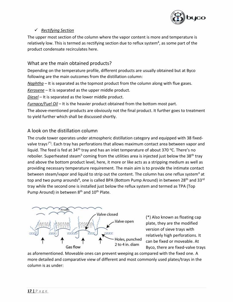
The crude tower operates under atmospheric distillation category and equipped with 38 fixed-
valve trays (*). Each tray has perforations that allows maximum contact area between vapor and
liquid. The feed is fed at 34th tray and has an inlet temperature of about 370 oC. There’s no
reboiler. Superheated steam5 coming from the utilities area is injected just below the 38th tray
and above the bottom product level, here, it more or like acts as a stripping medium as well as
providing necessary temperature requirement. The main aim is to provide the intimate contact
between steam/vapor and liquid to strip out the content. The column has one reflux system4 at
top and two pump arounds6, one is called BPA (Bottom Pump Around) in between 28th and 33rd
tray while the second one is installed just below the reflux system and termed as TPA (Top
Pump Around) in between 8th and 10th Plate.
(*) Also known as floating cap
plate, they are the modified
version of sieve trays with
relatively high perforations. It
can be fixed or moveable. At
Byco, there are fixed-valve trays
as aforementioned. Moveable ones can prevent weeping as compared with the fixed one. A
more detailed and comparative view of different and most commonly used plates/trays in the
column is as under:

18 | P a g e
One thing should be noted from the above table is the turndown ratio which is simply the ratio
of maximum to minimum throughput or design vapor throughput to minimum operable
throughput. It should be considered as a major selection parameter before designing the
column as it adds flexibility in terms of handling crude depending upon the nature of demand.
Above reference from Mas Transfer & Separation Processes by Binay K Dutta
5What’s the purpose of injecting steam? What kind of refinery is this?
This is called “Hydroskimming” type of refinery, one of the most common in the world. There
are certain reasons behind of calling it like that, some of them are:
✓ It has Hydro Treater Unit
The refinery is equipped with further processing of the naphtha and for this purpose Naphtha
Hydro Treater is being used at Byco along with reformer. This type of refinery must yield
Gasoline.
Main Refinery Types
For an ease of understanding, following are the main types of refineries:
1) Hydroskimming = Have Atmospheric Distillation Unit (ADU) and necessary treating
processes, it produces gasoline.
2) Topping = It just separates crude into main constituents using ADU, produces naphtha
but not gasoline.
3) Cracking = It has further treating units like Vacuum Distillation Unit (VDU), Catalytic
Cracker etc.
4) Coking = It adds further level of complexity in crude handling by employing further
processing of Vacuum Residue using Delayed Coking Process.
19 | P a g e
✓ Atmospheric Distillation with Steam as a Heating source
This type of refinery usually uses no reboiler. Steam mainly using as a main source of breaking
the feed into further fractions but it is debatable because it depends upon different
parameters, in many refineries the furnace is the main source of leading crude to its main
fractionating temperature. Since, steam generates from water alias ‘hydro’ and it also strips out
the vapor to the top section thus ‘skimming’ it. Hence, Hydro-skimming is termed.
The main aims that are normally achieved by injecting steam are: Since, it’s superheated hence,
acts as a heating source for the crude. Due to steam’s natural draft towards the top of column,
it adds bulk flow and thus enhancing the mass transfer as well as heat transfer rate, in short
transport phenomenon increases. It serves also as an equilibrium disturber, as the fuel oil
begins to add up in the bottom part it comes under equilibrium with vapors just above it,
eventually, decreasing the vapor flowrate hence, as the steam is carefully injected just above
the bottom product, it disturbs the equilibrium, resulting no halt and smooth flowrate.
In a nutshell, we can elaborate the purpose of injecting steam as:
- Steam distillation is used primarily to avoid reaching the degradation temperature for
thermally unstable materials.
- Steam lowers the partial pressure of the process fluid and so the boiling point, therefore, it
boils at relatively low temperature.
- It acts as an equilibrium disturber because there is an equilibrium maintained at each stage in
the fractionating tower it lowers the mass transfer rate, steam breaks this equilibrium as
explained above.
- It is used for stripping reasons as it helps in removing light tails from residue and heavier
products also it improves the quality of constituents – in side strippers, it improves the flash
point of middle distillates i.e. Kerosene – similarly, it removes lighter fraction from the bottoms
to facilitate Vacuum Distillation, if available.
- It helps in separating appreciable quantities of high boiling constituents.
4What does reflux system do? 6What are pump arounds?
Reflux system is located at the top of the distillation column. It consists of a condenser, a reflux
drum, and necessary fittings to control the reflux ratio. Simply, the condenser condenses the
vapor and re-enter into column while some of them is taken as an overhead product. It
improves the purity. It maintains the temperature and pressure profile.
A reflux system decreases the inside temperature while increasing the pressure.
Pump arounds are used for the same purpose as explained above. It takes the liquid from the
tower and decreases its temperature by passing through exchangers and fin fans and thus
helping in decreasing the temperature. This controls the temperature profile of the middle and
downward section of the column.

20 | P a g e
Two widely used terms are Internal and External Reflux; after condensation, when the
overhead product is reintroduced into the tower, the temperature at the top of the tower
decreases causing heavier fractions to condense back and flow downward and this is called as
Internal Reflux while the preceding being the External Reflux.
Pump Around: Point to be noted
Pump around streams reduce the vapor flow rate throughout the column. Therefore, the required column is smaller than what would otherwise be required if pump around streams were not there. The drawback to using more pump around streams is that they tend to reduce the fractionation because a more fractionated liquid is mixed after cooling with a less fractionated liquid a few trays above.
Reference from Alsahhaf, Alkilani Introduction to Petroleum Refining Engineering, 2010.
2Knock-Out Drums: purpose?
All the vent/flue gases coming out from different sections of the plant primarily, pre – flash and
crude tower. Some of it utilizes as an energy requirement of some part of the plant like the flue
gases are being used at Byco to fire the furnace and act as a super-heater in the boiler. The
gases are not directly utilized for the above-mentioned purpose as they also contain some
vapor fractions to which may be valuable. This, a knock-out drum is a final approach to collect
any liquid content present in the gas stream and then the rest vapor-free gas may use as a fuel
or vent out to the flare system.
3Flare System: Purpose?
The flare system is probably the most
commonly visible feature of any petroleum
refinery. They safely burn excess hydrocarbon
gases which cannot be recovered or recycled.
The burning ensuring that the plant is
operational and in running condition. Usually,
all the columns that releases flue gases as a
by-product have a pressure relieve system,
upon high pressure, it diverts the gases to the
knock drum followed by the flare system. By
continuous burning and nature of flame, we can diagnose the sudden rise/fall of pressure. Also,
if we simply vent out the off gases then the SOx, NOx and other hazardous gases can be
released along with, creating a dangerous environment as some of the gases are heavier than

21 | P a g e
air so it won’t disperse itself thus, it is better to burn them off. To ensure safety, pressure
regulation and monitoring this part is very important. At Byco’s control room, a dedicated
camera continuously monitors the flare system. Some part of steam is also injected with the
flue gases to avoid any soot and ensures clean burning Steam is usually added to the gases to
increase turbulence in the gas flow. This increases air intake that helps to achieve complete
combustion and smokeless flaring. The flare system using at Byco commonly known as Elevated
Flare System.
Reference from A. Kayode Coker (2007). Ludwig's Applied Process Design for Chemical & Petrochemical
Plants, Volume 1.
Stripping Section
There are mainly two strippers present along with the main crude tower. The two strippers are:
➢ Kerosene Stripper
Kerosene separated from the crude tower is injected from the top to the stripping column
where it gets interacted with upcoming stream of steam which extracts out the lighter contents
while Kerosene extracts out from the downward section. This further move towards heat
exchanger followed by fin fan* and trim cooler** to cool the rundown product. This process
enhances the purity of product as well as maintain several properties like flash point etc.
At Byco, almost all the Kerosene is injected to Diesel to increase its yield and they don’t market
simple Kerosene as a commercial product.
JP-I: Jet Fuel Production
Depending upon the demand JP-I is prepared. When there’s a requirement then some part of
this Kerosene goes further for the MerOx treatment (which will be discussed later) and then the
sweet product with very low Sulphur content is obtained and the rundown is collected as a final
product.
Static Charge build up in JP – I: Hazard!
Usually, as the crude refines increasingly all of its electrical conductivity decreases which cause
a higher tendency to accumulate static charge which leads to explosion. This issue became
more severe in the early use of automotive and aviation fuel when there was no source present
to overcome this issue. Back in 1983, Stadis® was invented, it acts as a Static Dissipater Additive
widely used in aviation and automotive fuels to increase the electrical conductivity of fuel. It is

22 | P a g e
based on Dinonylnaphthylsulfonic acid and chains of other organic compounds. At Byco, it is
added in JP – I fuel as a chemical additive.
Reference from innospec™ Stadis®
➢ Diesel Stripper
For Diesel, the stripper utilizes when there is a deflection in the properties. It has the same function as per mentioned above. It also maintains the cloud point, flash point etc. of the fluid. Only HSD (High Speed Diesel) is obtained as there’s no demand to produce LSD (Low Speed Diesel). Byco used to produce ultra-winterized Diesel some two years ago, but due to less demand it is not producing anymore.
Accumulator
Previously, it has been explained that the Naphtha is mainly coming from two sections, one as a
10% recovered Naphtha from pre – flash and the rest from the crude tower. The both streams
combine and further goes to the accumulator part where a 3 component, 2 phase mixtures is
obtained. Water is drawn off continuously from the bottom which is further used in the
desalter as a mixing medium and this is also tested frequently for any iron or contamination
content. Off-gases vent out from the top while the naphtha recovers from the middle section.
Naphtha Splitter
It is a column with process very similar to the stripping and having sieve trays inside. As the
name suggests, it splits the naphtha into lighter and heavier fractions. From accumulator, it
moves to the pre-heat train to meet the process heating requirement and then comes here and
split into two parts:
Light Naphtha
Light Naphtha which ejects from the top while Heavy Naphtha separated from the downward
section. Some part of these two streams are stored in the storage tanks for accidental usage
especially when startup is required. Light Naphtha goes towards the LSU (LPG Separation Unit)
(which shall be discussed) followed by MerOx treatment and then it stores in the LPG Bullets.
Heavy Naphtha
Heavy Naphtha is considered as an export item. Hence, it moves to two sections depending
upon the requirement and circumstances, one towards the MerOx treatment followed by
storage while the other heavy naphtha stream goes to the Naphtha Hydrotreater (NHT) where
it forms a feed for the reformer and finally reformate/MS or Gasoline is obtained from it.

23 | P a g e
Why *fin fan is placed before **trim cooler when cooling down the product?
This is due to the heat transfer rate. The forced convection from fin fan causes high change in
temperature as compared to trim cooler. Although, it doesn’t produce high delta in
temperature but still act as a better cooling medium. Secondly, ambient air is blowing which
doesn’t require any cooling of itself and available in bulk quantity. It also reduces the heat load
on the trim cooler as well as reduces the time cycle of cooling tower. Trim cooler is the cooler
which only contains water in its tubes as a cooling medium. Also, fin fan is also highly favorable
as it creates a forced draft for evaporation and cools down the product till it reaches wet bulb
temperature.
Additives Used in Heavy Bottoms
Poly alkyl methacrylate (PMA) is used as a Pour Point Depressant. Viscosity of bottom’s product
i.e. furnace/fuel oil and refined lube oils is of higher value and the quantity of wax in it results in
higher value thus increasing the pour point of the oil. At low temperatures, the wax tends to
separate, preventing oil flow, and hindering lubrication. PPDs are added to reduce the pour
point of the oil while keeping the viscosity benefits of the wax. They alter the crystal growth
size of the wax thus ensuring good flow ability. This is most commonly known as “Cutter-Stock”.
Reference from HiTEC® PPDs by Afton Chemicals™, U.S.A
Naphtha Splitter Simplified Diagram
E-1
Naphtha
From
Pre Flash
Naphtha From
Distillation TopP-4
Water
Out
P-5
Gases
Out
Naphtha
Splitter
E-2
E-3
P-6
P-7
E-4
E-5
P-15
P-13
P-14
P-8
V-1
FI
I-1
Light
Naphtha
To LSU
Heavy
Naphtha
To NHT
Accumulator

24 | P a g e
MerOx Unit
The term MerOx is a portmanteau of Merceptans Oxidation. The unit was developed by UOP®,
U.S.A. and the reactor uses the custom catalyst developed by them. The main aim of using this
system is simply purification. Merceptans are Sulphur based compounds that are hazardous to
the equipment as well as act as a contaminant for the fuel. They are Alkyl Sulfide Halides (RSH).
More Sulphur content make the fuel sour which is undesirable. This system ensures effective
treatment in this regard and removes all the disulfides and metallic compounds. The process of
reducing sulfur content often termed as “Sweetening” and can be elaborated as:
Why Sulphur/Mercaptan is injurious?
If it presents in the fuel, then upon combustion produces NOx and SOx along with other
hazardous gases which is poisonous and injurious to both health and environment. Sulphur is a
soft compound in general and upon high temperature it can cause dead spots in the reactor or
in any column upon deposition which should be highly prevented. Mercaptans impart foul smell
as well as can cause corrosion and can reduce octane number by reacting with octane inhibitor.
What is happening in MerOx unit?
Simply, MerOx is the oxidation of mercaptans to alkyl disulfide. The reaction proceeds under
caustic environment in the presence of catalyst which is a metal – preferably iron – based
chelate, it diffuses on the surface of the activated carbon to increase the surface area. Air
injected as an oxidation medium. The chain of reaction involves removal of Sulphur related
compounds and caustic regeneration. The caustic used at Byco is of 50 oBe which further gets
diluted according to the requirement. It converts mercaptans into Alkyl disulfides. The reactions
are as under:
At Caustic Pre-Wash: NaOH + H2S yield NaSH + H2O, other reactions involve here are:
RSH + NaOH yield NaSR + H2O & H2S + NaOH yield Na2S + H2O & Na2S + H2S yield NaSH
At Extraction: 2RSH + 2NaOH yield 2NaSR + 2H2O
Regeneration of Caustic: 2NaSR + O2 + 2H2O yield 2RSSR + 4NaOH
Overall: 4RSH + 02 yield 2RSSR + 2H20
Formation of Sodium thiosulphate: NaSH + O2 yield Na2S2O3
Removal Process
Removal of hazardous constituents like sulfur
and its compound, called as desulfurization
Conversion Process
Removal of mercaptans by means of
oxidation, called as conversion process.

25 | P a g e
MerOx System at Byco There are mainly four MerOx systems working
currently under one unit based on the type of
final product, all serve for the same purposes
as explained above. They are as under:
➢ Kerosene or JP – I MerOx
If it is required to produce jet fuel, then
Kerosene under goes with MerOx treatment.
First, it goes to Pre-washer where caustic is
showered against the upcoming stream of Kerosene. Further it moves to the sand filter where
there is a bed of activated sand particles that can remove any contaminants and excess caustic.
From here, air is injected to provide an Oxygen based medium in the reactor where, main
treatment is performed. The product further goes to water wash to neutralize or remove the
disulfides/metal compounds followed by a settler where separated caustic is separated and
goes to caustic recirculation. The product then moves to the salt bed to remove any salts
followed by sand filter and finished sweet product.
➢ Heavy Naphtha MerOx
The process for Heavy Naphtha
MerOx is almost similar as
depicted previously. The main
difference is that, it doesn’t
have to go through the sand
filter. It goes to pre-wash
followed by reactor and settler
and finally run down.
➢ Light Naphtha MerOx
The process starts by
introducing light naphtha to the batch caustic pre-wash from where, it bubbles out from the
top. A demister/coalesce helps in restricting entrainment of caustic. It helps in removing any
H2S, if present followed by a Caustic settler, reactor which has an alkaline bed of catalyst along
with charcoal bed and then the sand filter. After that, it runs down as a sweetened final
product. In the batch, caustic is filled to around 70% limit with concentration of 12 to 15 oBe.
26 | P a g e
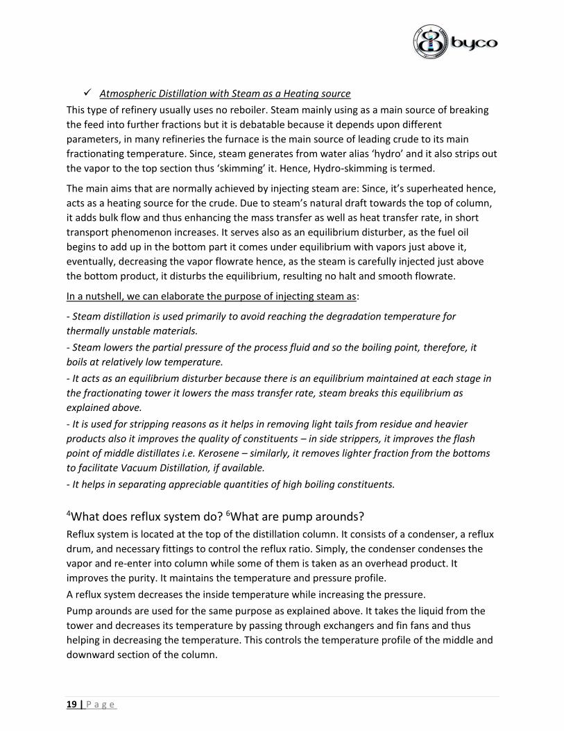
➢ LPG MerOx
The process for LPG is slightly different as
compared to the above-mentioned
treatments. The LPG coming from LSU first
goes to the pre-washer. The pre-washer is
filled with 70% Caustic by volume and LPG is
directed from the bottom and bubbled out
from the top. At the top, there is a coalesce
that traps caustic from moving along with LPG,
this is also known as Batch Caustic Pre-wash.
From here, it moves to the extractor unit
which is equipped with trays with bubble caps,
here, caustic is showered against the upcoming stream of LPG and caustic is separated out from
the bottom. From here, LPG Stream moves to a settler to settle out any caustic/water content
followed by a water wash to remove the disulfides and separated contaminants and salt bed to
remove salt traces and then, sweetened LPG is taken out as a product and stored in bullets.
Why Use Caustic Pre-Wash?
It can dissolve low molecular weight mercaptans. It has the tendency to dissolve Hydrogen
Sulfide gas. It also converts mercaptans into Sodium Mercaptide which is the intermediate
product.

27 | P a g e
Spent Caustic Handling by Partial Oxidation of Sulfidic Caustic
The handling of contaminated sulfidic rich spent caustic can be a cumbersome process due to
excessive Ph, High BOD (Biological Oxygen Demand) it is not feasible to dispose it easily. The
process oxidizes the spent caustic causing a low pH effluent to generate which can be further
treated at the waste water treatment system. The spent caustic is mainly the one which is used
as a batch caustic prewash.
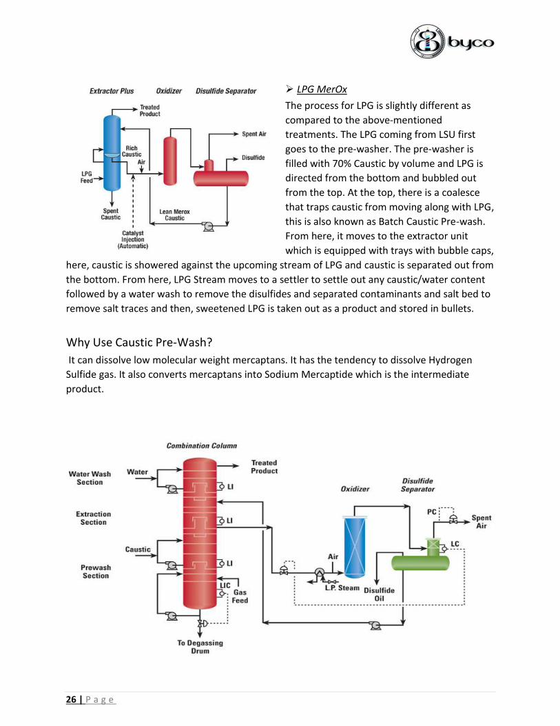
Caustic Recirculation & Re-generation
The utilized and diluted caustic coming out from different MerOx section combines altogether
to form one stream and passes through a UOP® designed catalyst followed by a pre-heater
which heats it to around 45oC. From here, it moves to the oxidizer column where a stream of air
is injected to provide an Oxygen based environment. The oxidizer helps separating disulfides
from the caustic then the caustic moves to the main unit equipped with coal bed at the bottom
and Raschig Rings on the top. The caustic and disulfides forms a separate layer due to density
difference and pass through the coal bed while the gases move upward through the rings and
vent out. Disulfides is separated from the top while caustic is separated from the bottom. For
extraction (MerOx WS™ catalyst) and for fixed-bed sweetening (MerOx FB™ catalyst) were
developed. These catalysts are produced as liquid catalysts which enable easier handling. They
are termed as WS and FB Reagent commonly. The above shown diagram depicts the
combination process for effective treatment which can also be utilized.
All the above diagrams are taking as a reference from UOP MerOx™ treating process

28 | P a g e
UoP® based MerOx Treatment of Light Naphtha at Byco
Displayed TextE-1
E-3
E-4
E-6
E-7 Settler 1
Equipment ListDescription
Batch Caustic Pre Wash
Sand Filter
Settler 2
Main Reactor w/ catalyst

29 | P a g e
UoP® based LPG MerOx Simplified Schematic at Byco
Pipeline List Equipment, Valve & Instrument List
Name Description Name Description
P-10 Rich Water Outlet BPW-101 Batch Caustic Pre-Wash
P-11 Pure Water Inlet E-102 Caustic Extractor
P-12 LPG Stream P-100 A/B Centrifugal Pump (B not shown)
P-14 MerOx Treated LPG PW-104 Water Pre-Wash
P-15 Salt Content Drain S-103 Main Settler
P-19 Caustic Level 1 SB-105 Salt Bed
P-2 Spent Caustic V-100 Check Valve or NRV
P-20 Caustic Level 2 V-101 Actuated Control Valve
P-26 Water Inlet to Pump V-102 Angled Pressure Relief Valve
P-28 LPG from LSU LT 01 Level Measurement & Transmit
P-3 Bubbled out LPG LI 01 Level Indicator
P-4 Caustic Out P-5 LPG to Settler P-6 Drain P-9 LPG to Water wash

30 | P a g e
UoP® based Kerosene & Heavy Naphtha MerOx at Byco
Displayed TextE-1
E-2
E-3
E-4
E-6
E-7/E-8
E-11
E-14
E-16
Reactor
Caustic Prewash
Settler
Reactor
Salt Bed
Sand/Clay Filter
Equipment ListDescription
Water Wash
Settler
Caustic Prewash

31 | P a g e
Typical Caustic Regeneration System
Simplified PFD is developed using Microsoft Visio. Actual process components may vary.
Doctor Sweetening Process/Test
One of the first and earliest effort in the field of sweetening was made by Mathew L. Kalinowski
in 1954. The process involves around the chemistry of removing mercaptans as follows:
Litharge (Lead oxide) dissolves in 5-30 weigh t% concentrated caustic forming Sodium Plumbite
or Doctor’s Solution as:
PbO + 2NaOH Na2PbO2 + H2O
Doctor’s solution is then mixed with petroleum product, the two remain immiscible but
mercaptans mixed with it forming lead mercaptide, as:
2RSH + Na2PbO2 (RS)2Pb + 2NaOH
The product is then treated with powdered sulfur which reacts with lead to form blackish lead
sulfide commonly known as disulfide, as:
(RS)2Pb + S RS-SR + PbS
32 | P a g e
If no Sulfur is introduced, it oxidizes as:
2(RS)2Pb + 2NaOH + O2 2RS-SR + 2Na2PbO2 + 2H2O
This disulfide forms a layer which can then be separated but this process doesn’t remove Sulfur
completely and may increase the sulfur and lead content. It is a laborious process which needs
frequent checking of the sulfur and lead content because both are now considered as illegal to
be present in the petroleum product above certain level as well as a threat to human life. UOP
MerOX Process was introduced to overcome this issue which has already been described above.
The process now uses widely as a testing methodology to describe the sourness/sweetness of
petroleum product.
Test for Sweetened Product The procedure for testing involves the following steps: - Take some amount of sweetened product.
- Add approximately equal amount of doctor solution that is Sodium plumbite.
- Add suitable amount of powdered sulfur.
- If there is brownish color or somewhat black precipitate of PbS then the doctor test is positive
and the product is sweetened. If the color of sulfur crystal remains unchanged then the test is
negative and vice versa.
Reference from Doctor Sweetening Process Using Sulfur Mathew L. Kalinowski, Chicago, Ill., assignor to
Standard Oil Company, Chicago, a corporation of Indiana, March 11, 1954
Naphtha Hydro Treater Unit (NHT)
This unit is designed for hydrogenation process or mainly to saturate olefins and double-
bonded hydrocarbons into single bonded compounds. Heavy Naphtha coming from the splitter
is stored as a product and some excess part comes for hydro treating to make final product like
gasoline. Secondly, it removes the undesired compounds as well that may lower the properties
of final product like its RON* and RVP**. It prepares the inlet feed for the reformer as the
reformer has precious catalytic reactors and the catalyst are very sensitive to Sulphur and other
compounds which leads to catalytic poisoning hence, hydro treating is very necessary.
Following important reaction takes place here:

33 | P a g e
Main Reactions Hydrodeoxygenation: Converts organic oxygen content into water.
Hydrodesulphurization: Removal of Sulphur and its compounds.
Hydrodenitrogentaion: Removal of Nitrogen and its organic compounds by conversion into
Ammonia which utilizes in the pre-flash as well.
Hydrocracking: Breakdown of large hydrocarbon chains into smaller chains. The last important
factor is, it also removes aromatic compounds especially Benzene and its isomers as we already
know that Benzene is carcinogenic and the emission cause cancer so any traces of it should not
be present in gasoline.
Hydrodemetallization: Conversion of hazardous metals and organometallic compounds into
metal sulfides.
Main Process Hydrogen is mixed with the incoming stream of Heavy Naphtha followed by pre-heating the
stream to reduce the heat load and then it moves to the cylindrical furnace where it reaches to
its process temperature of around 300oC followed by a reactor. The reactor Co-Mo catalyst
inside which provides necessary process conditions from here, it goes to air coolers to cool
down the product followed by a product separator where off-gases vent out. The reactor has a
demister bed inside to form coalesce. The liquid separated from the separator further moves to
the desulphurization tower where a temperature profile is maintained and as the name
suggests, Sulphur and its related compounds separated out easily. The final product appears to
be the feed for reformer. Streams in desulfurizer can be traced from the diagram shown on the
next page. For reference, there’s a recirculation of product stream from main furnace, the
product stream exchanges heat with the incoming stream, some part of product stream passes
through a boiler or a Waste Heat Recovery system to generate steam.
What’s RON & RVP?
RON stands for Research Octane Number, a necessary parameter that explains the quality of
gasoline as an anti-knocking inhibitor. N-hexane has an octane rating of zero while branched
octane has an octane rating of 100. They blend together to form the standard RON based
gasoline for the market that is 87. RVP stands for Reid Vapor Pressure, this is indeed an
important parameter of gasoline to understand as well. Vapor Blockage is a problem that used
to be occur in automobiles fuel line that runs on gasoline due to its high vapor pressure it forms
a cloud inside the pipeline causing the fuel pump to cease. RVP is the test carried out in a
confined space including air and moisture in the closed environment at slightly elevated
temperature to depict the quality of gasoline of forming vapor blanket

34 | P a g e
Simplified Process Flow Diagram of Naphtha Hydro Treater Unit at Byco
Name Description NameE-1/E-2/E-9 Pre Heat E-4
E-10 De Sulferizer E-5/E-13
E-12 Separator E-6/E-11
E-16 Waste Heat Recovery Boiler E-7
E-3 HydroTreater Furnace
Equipment ListDescription
HydroTreater Reactor
Fin Fan
Trim Cooler
Product Separator
Naphtha
In
P-1
V-1
P-2
Hydrogen
F/ Reformer
E-1
E-2P-3
P-4
E-3P-5
E-4
P-6
P-7
P-8
P-9
E-5
P-10
E-6
E-7 P-12
E-8E-9
E-10
P-16
Reformer
Feed E-13 E-11E-12
To
De Butanizer
Fuel Gas
P-25
P-27
P-28
E-16
Reformer
Feed SteamWater

35 | P a g e
Reformer Section
The reformer section aims to covert the straight chain compounds into branched chains and
convert the feed from naphtha hydro treater into high value of RON to meet the specs
requirement of gasoline. The process involves the reactors designed by UOP® and they are
using their own Pt-Rh catalysts. These catalysts are sensitive as explained above hence, before
giving feed to the reformer, it must have already been treated before with NHT. These catalysts
can be regenerated but after 3-4 times, new installation is mandatory.
Main Process The product obtained from the NHT section is fed to a pre-heater and then it moves towards a
main furnace and series of reactors. There are three individual reactors. The furnace provides
the necessary process temperature requirement and in reactors, reforming and platforming of
naphtha is performed, linear chains converted into branched chains of more valuable
components. From the reactor, it goes to the product separator where off-gases and primarily
hydrogen is obtained followed by a stabilizer section where a reboiler ensures the continuous
circulation and thus providing the stabilizing conditions as well. The product obtained is termed
as reformate/motor spirit or premier motor gasoline. No further additional blending is required
as the gasoline obtained has already standard octane number.
Where the Hydrogen comes for NHT? During platforming, hydrogen is generated as a byproduct. The good thing is, it is recoverable and it is recovered from the reformer section and stored in storage tanks from where, it circulates continuously to the NHT for hydrogenation. There’s a compressor section located along with reformer at Byco. There are two of them called as: Recycle Compressor and Booster Compressor. The recycle one, takes the Hydrogen from the reformer and with the help of booster compressor it injects it to the NHT section.
Chemical Additives Used Tetrachloroethylene commonly known as Perc is injected to the reformer reactor. There are
two main purpose of it:
It provides chlorine enriched environment that is necessary to drive the reactions.
The nature of reaction needs Chlorine as a reaction medium but excess chlorine can cause
disruptions in the reactions and will favor more of the hydrocracking and eventually less yield of
reformate. To overcome this issue, sometimes water based ethanol is injected in the reactor to
suppress the chlorine content.
It controls the moisture content inside.
Moisture content is not favorable for the reaction as it extracts out chlorine from the catalyst.
When there is an excess of moisture content, more Perc is injected.

36 | P a g e
Apart from the reformer section, Methyl cyclopentadienyl manganese tricarbonyl commonly
known as MMT is added as an anti-knock inhibitor at the tank farm area, this is acted as an
Octane booster. The Gasoline extracted from the reformer is colorless usually and dye is added
to give a distinguished color in it.
Main Reactions The reactions in reformer mainly occur in the acidic and metallic side of the Pt-Rh catalyst. To
develop the acidic nature in the catalyst usually Chlorine and Fluorine based additives are used.
Thus, Perc is used to serve for this purpose. As I have mentioned in the above section about the
use of Perc, here, another purpose has also been explained.
Following reactions are occurring in the reformer unit:
- Dehydrogenation of Naphthenes
The important Aromatic reaction from Naphthenes
is the dehydrogenation of alkyl cyclohexane. This
reaction proceeds rapidly and is favored by high
reaction temperature and low pressure. The metallic side of the catalyst promotes this
reaction. This reaction is highly desirable as it produces Hydrogen as a side-product which is an
essential feed requirement of NHT. The reaction is endothermic in nature and takes place
rapidly, essentially lead to completion.
- Hydrocracking of Paraffin and dealkylation
The acidic function of the catalyst favors this reaction
under high pressure and temperature. The paraffin
cracks and disappear from the gasoline boiling range, the

37 | P a g e
remaining aromatics concentrate the gasoline resulting in higher octane number. Usually,
Hydrogen is consumed during this reaction and the net liquid content is reduced, making this
reaction undesirable to some extent. Dealkylation reaction has the same properties as
explained above, the sole purpose is to remove the alkyl group.
- Isomerization (mainly of n-paraffin)
This reaction is favored by acidic part of the catalyst and
its main function is to form branched chains from straight
run chains or to form ring arrangements of certain
aromatics. The isomerization of alkylcyclepentane to
alkylcyclehexane must take place before it gets converted to aromatics. Reaction occurs rapidly
at optimum temperature.
- Dehydrocyclization of Paraffin
This reaction is favored by low pressure and high
temperature and both acidic and metallic part of the catalyst
plays role in the promoting the reaction. Its main purpose is
to perform molecular rearrangement of paraffin to
Naphthenes. This is considered as the most difficult reaction
to proceed. Paraffin cyclization increases as the molecular weight of the paraffin increases.
What does SOR & EOR mean?
SOR/EOR is the condition mainly associated with the reactors/vessels equipped with catalyst
bed. Start of Run condition means the temperature and main process parameters that obtain
when the catalyst is working at its maximum efficiency or particularly when it is new as there’s
less purge and more desired product under standard operating conditions. When it gets
deactivated after certain time, the purge increases and the process parameters tend to deviate
from the actual condition, the results obtained at that time is called End of Run condition.
38 | P a g e
Why the series of reactor is smaller at feed but larger on the product side?
There are three reactors placed in ascending order in terms of their size. Since, the reactant
(feed) has obviously, no product content at the beginning hence, less surface area of catalyst is
required to yield the maximum outcome. As it enters the next reactor, some conversion of
reactant has already been done & product content is increased so, the remaining reactant
requires more surface area to yield and vice versa.
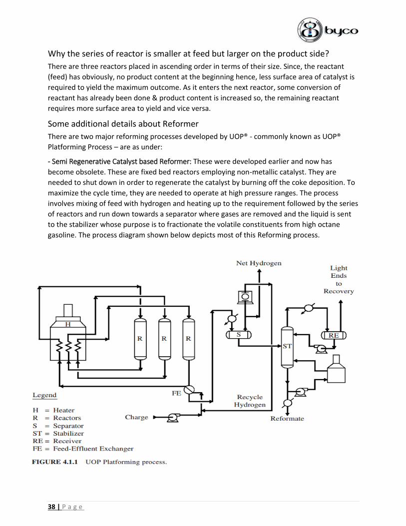
Some additional details about Reformer
There are two major reforming processes developed by UOP® - commonly known as UOP®
Platforming Process – are as under:
- Semi Regenerative Catalyst based Reformer: These were developed earlier and now has
become obsolete. These are fixed bed reactors employing non-metallic catalyst. They are
needed to shut down in order to regenerate the catalyst by burning off the coke deposition. To
maximize the cycle time, they are needed to operate at high pressure ranges. The process
involves mixing of feed with hydrogen and heating up to the requirement followed by the series
of reactors and run down towards a separator where gases are removed and the liquid is sent
to the stabilizer whose purpose is to fractionate the volatile constituents from high octane
gasoline. The process diagram shown below depicts most of this Reforming process.

39 | P a g e
- Continuous Catalyst Regeneration (CCR) based Reformer:
This is an improved version of the SR based reactors where the catalysts regenerate
continuously without shutting down the process. The catalysts generally withdrawn from the
last reactor. The catalysts regenerate in a controlled environment and then transfers back to
the first reactor. It favors low pressure operation and produced more refined high-octane
product. Aromatics passes through it relatively unchanged, Naphthenes react easily ad paraffin
are most difficult to convert. Napththas are classified as:
Lean
Low Naphthene & Aromatic content which
yields less reformate
Rich
Contains high proportions of Naphthene
content which yields more reformate

40 | P a g e
Nature of Catalysts
Heterogenous, composed of base support (usually Al2O3) on which active metal is placed,
bimetallic (normally Pt-Rh), to develop acid functionality a promoter based on Cl or F is added
as explained above.
Reactor Pressure and Temperature
For practical purposes, a close approximate for pressure is the last reactors’ inlet pressure, if
pressure decreases it causes to yield more hydrogen and reformate dropping the temperature
which affects the quality as well as it causes to increase the coking rate of the catalyst as well.
The reactors’ temperature can be classified as:
Diagram and literature reference from UOP® Platforming™ Process by Lipinski, Baird & James, Des
Plaines Illinois. Simplified PFD can be seen on the next page.
Rough Description showing how the reformer reactor looks from inside
Weight Average Inlet Temperature (WAIT)
Can be obtained by multiplying the product
fractions with the inlet temperature
Weight Average Bed Temperature (WABT)
Can be obtained by multiplying the product
fractions with the average of inlet & outlet
temperature

41 | P a g e
Name Description NameE-1 Main Furnace E-9
E-10 Hydrogen Suction Drum E-16/E-18/E-7
E-11 Recycle Compressor E-17/E-19/E-8
E-12 Booster Compressor E-2/E-3/E-4
E-13 Stabilizer E-20
E-14/E-15/E-5/E-6 Pre Heat
Separator
Equipment ListDescription
Hydrogen Separator
Fin Fan
Trim Cooler
Reactors
E-1
E-2 E-3E-4
P-1
P-2 P-3
E-5E-6
P-4P-5
P-6
P-7
P-8
P-9
Reformer Feed
From NHT
E-7
P-10
E-8
E-9
P-11
E-10
P-12
P-13
E-11 E-12
P-14
P-15
V-1
P-16
E-13
E-14
E-15
P-17
P-18
P-19
P-20
P-21
P-22
E-16 E-17
P-24
Reformate
Run Down
E-18 E-19P-26
P-29
E-20
Fuel Gas
Fuel Gas
Hydrogen
To NHT
P-32
Recirculation from
Main Furnace

42 | P a g e
LPG Separation Unit (LSU)
Commonly, LPG is produced by separating out the main gaseous components from the light
naphtha stream and then mixed it accordingly to give a composition of LPG. But, at Byco, the
usual composition of 60-40 ratio of butane propane is not practiced, they only consider the
main properties of LPG that should meet the standard requirement. One of which is called
Weathering, an evaporation test of LPG liquid content which depicts the result.
Here, the LPG unit mainly consists of: 1) Depropanizer 2) Debutanizer 3) Deethanizer
Out of which deethanizer is not operational as it doesn’t capable to operate under defined
process parameters so they are using it as a bypass.
Main Process Light naphtha moves through the above three mentioned columns to remove the gaseous
components but ethane is not removed while on Depropanizer, propane is removed to some
extent with traces left same for the debutanizer. All the columns are equipped with reboiler
inside that ensures continuous circulation. The final LPG product is taken from the top of
Depropanizer and forward it to the reformer unit followed by storage in LPG bullets. The final
product has major part of ethane with traces of butane and propane.
In a simplified and general manner, light naphtha first goes to Deethanizer, from top ethane
gets removed, the bottoms go to Depropanizer, from top propane gets removed, the bottoms
go to the final Debutanizer where butane gets removed while the light naphtha obtains from
the bottoms which further goes to MerOx Treatment.
Sources
LPG is obtained from two sources one from the top of the stabilizer in the NHT and second from
the LSU unit. Customarily, the top product of stabilizer is termed as butane while the product
separated from LSU is called propane. This should not be confused with the actual products.
Both are termed as LPG in reality.
Heavy Naphtha Light Naphtha
From MerOx treatment, one stream
goes towards storage section while
the latter goes to NHT unit. It is a
major constituent of Gasoline as it
contains C7>.
From LSU, it goes to the MerOx
treatment followed by storage. Light
Naphtha mainly constitutes C7<.
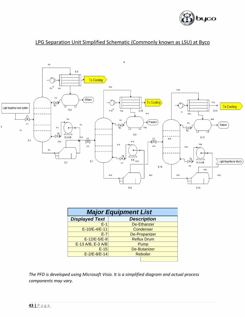
43 | P a g e
LPG Separation Unit Simplified Schematic (Commonly known as LSU) at Byco
Displayed TextE-1
E-10/E-4/E-11
E-7
E-12/E-5/E-9
E-13 A/B, E-3 A/B
E-15
E-2/E-8/E-14
Pump
De-Butanizer
Reboiler
Major Equipment ListDescription
De-Ethanzer
Condenser
De-Propanizer
Reflux Drum
The PFD is developed using Microsoft Visio. It is a simplified diagram and actual process
components may vary.

44 | P a g e
(OMS) Oil Movement & Storage alias Tank Farm
The OMS section at Byco is mainly responsible for safe and effective handling of crude as well
as final product. Storage, Chemical dosing, pumping, logistics, transportation and various other
responsibilities are on their shoulders. Skimming of oil is also done here. At main process area,
there are underground tanks which serves as a rejected form of oil which may contain other
chemicals or water content as well. The oil moves with its own head to the OMS area where oil
and water are separated and the water after certain treatments flash out to the sea. The
separated mixture of oil is called Slop Oil which stores in a separately dedicated tank. There is
testing system of various product present at the tank form which is called TMB test (Top Middle
Bottom), this test provides the composition analysis of either raw crude or the finished product.
Following two types of tank are present at Byco:
Fixed Roof Internal Floating Disc
For all the product storage needs, this type of tank is mainly used. It consists of a fixed roof at
the top and an internally floating disc which rises or falls depending upon the level of fluid
inside. As the vapor pressure of refined product is usually very high and at elevated
temperature, this can cause serious vapor build up inside the tank hence, to overcome this,
internal floating disc is mainly used. As the liquid stays below the disc while its accumulated
vapor stays out from the rims and remains at top under fixed roof which ensures safe storage
and lower the evaporative loss.
External Floating Roof
For crude storage, this type of roof is used mainly used, mainly to overcome evaporative losses.
It keeps pressurized the crude all the time and usually has a very little vapor build up inside due
to lesser or no space. The roof floats over the liquid as the liquid rises and has nothing to cover
at the top. It prevents losses of valuable components from the crude, as there are thousands of
contents present in it all having different boiling point as well as different vapor pressure and if
it vents out. It can cause to build up vapor cloud which can explode as well as losses can lower
the yield of valuable products.
Piping System & Safety
There are mainly five pipes that are connected to an individual tank the system of operation is
almost the same:
RUNDOWN: From where, the product comes to store in the tank.
SUCTION: From where, the product ships to the bowsers.

45 | P a g e
CIRCULATION: Internal circulation mechanism, to maintain the level.
FIRE WATER LINE AT TOP w/ FOAM LINE: It only operates when there might be a fire.
DRAIN/TESTING LINE: To drain or take any sample.
There are breather systems situated at the top that has perforations inside which permits
ventilation and ensures a safe pressure inside the tank.
Level Measuring
The control room has annunciators inside which displays the parameters associated with each
tank and beeps alarm when there’s an over filling of head. FWL (Free Water Level) and TOV
(Total Overhead Volume) are two main parameters that is checked frequently inside the tank.
There are three methods widely practiced at Byco:
BOB GAUGE: It has a bob corresponding to the inside free height of the tank. The needle
present outside moves down when the liquid level rises to give the free height value and vice
versa.
DIP TAPE: This is considered as the most efficient and accurate level measuring method which
consumes time as well as energy. The tape has a metal cylinder at the bottom and the operator
has to dip it till it reaches the datum, the final height can be visible once it is taken outside. A
special marking is used on the tape which upon meeting with liquid turns pink and final height
can be depicted. For free water level, a special water finding paste is used.
ATG SYSTEM:
Automatic Tank Gauging System is an electronically measuring instrument. It is a
multifunctional device and can measure:
Density
Temperature
Flowrate
Head
Volume
LPG Bullets
LPG is a liquefied gas and hence stored in a liquid-gas state in a pressurized vessel called as LPG
Bullets. The vapor can be liquefied upon increasing the pressure or lowering down the
temperature. As the LPG is commercially available in gaseous form, it doesn’t store fully in the
tank but in variable percentage with liquid. As the vapor extract out from the top, the liquid
tends to boil and generates more vapor and thus, this cycle continues. Water showering from
outside the tank is usually done to maintain temperature gradient.

46 | P a g e
Utilities Section
The utilities section at Byco deals with the operation of cooling towers, handling of raw water
and it treatment as well as the operation of boiler to generate the steam.
Boiler Operation
The boiler present at ORC – I is a D-type low pressure water tube boiler. It utilizes the treated
sea water from the RO and softener plant to generate superheated steam. The water after
treatment comes to the treated water tank where it moves to the boiler section. Amine is
injected in the water stream to nullify Oxygen content followed by de-aerator* where steam is
injected from the bottom which strips out Oxygen from the water then it moves to the
economizer where it is pre – heated to minimize the further heat load then it moves to the
steam drum where saturated steam is generated followed by a super-heater which further
forms superheated steam to be utilized in distillation area.
How can we recognize a water-tube boiler?
Usually, water tube boiler has two separate drums which can be identified easily one is called
the steam drum and the second one is called the mud drum.
Types of Blowdown and how can scaling be prevented?
Scaling is a cancer to the boiler. It can cause massive distortion upon exploding the boiler due
to different pressure and temperature failure conditions. While, it I recommended to use zero
TDS and zero hardness water in the boiler but there is some hardness present in it which
cannot be fully removed hence a blowdown is very necessary at the bottom which takes out all
the excess water and contaminants along with. There are mainly two types:
Continuous Blowdown: Usually some of the water accumulates at the bottom of the steam
drum which should be taken out and for this purpose continuous blowdown is used.
Intermittent Blowdown: It is a high-pressure blowdown, can be performed periodically to
extract out any scale present inside along with extra water.
*Corrosion Issue: Prevention method
As I have mentioned about the de-aerator, this serves as a corrosion inhibitor. Steam is injected
in the water to perform kind of stripping as it takes out the Oxygen as well as the dissolved
Carbon dioxide. Since, CO2 can cause sweet corrosion in the form of acid attack. Carbon dioxide has
the tendency to form Carbonic Acid which corrodes the transmission lines and the boiler itself.

47 | P a g e
ORC – II, RO Plant Operation & Water Treatment
There is a water channel constructed at Byco which serves as an open basin to store raw sea
water. The pH of raw water is acidic in nature around 6 – 6.5. Most of the chemical dosing is
performed outside the main RO plant. The water first treated with caustic which boosts the pH
then to overcome the biological growth HOCl is added which is a main source of oxidizing agent
and suppresses the amount of Oxygen present in it followed by the addition of a polymer-based
chemical which serves the purpose to form chains and brings the flocs or coagulates to the top.
From here, it goes to the DAF tank (Dissolve Air Floatation) where air is injected inside and the
floating contaminants skim out from the top from here it goes to a vessel where it gets
saturated with air and the run down in the tank and then it goes to two main RO sections.
Sodium met bisulfide and anti-scalant is added before RO treatment which reduces chlorine
content. Till here, all the visible particles have been removed.
Sea – Water Reverse Osmosis (SWRO)
The water is pumped from the tank to a cartridge filter followed by a multimedia filter (MMF)
which has a layer of silica and gravels. After washing out, it moves to the RO filters via high
pressure pumps. The membranes are of circular type water injects from the outer circular are
and travels to the center from the tiny pores of 0.01 Angstrom and termed as permeate which
is taken out from the center the rest being outside is called reject which drains out in the sea.
Energy Recovery Turbine: recovery of energy from water
The permeate coming out has a high pressure and lot of energy present in it. To minimize the
pump, load some part of it is recirculated back to a turbine which adds energy to the moving
impeller of the pump resulting in high pressure recovery.
Brackish Water Reverse Osmosis (BWRO)
The water coming from the previous RO reaches here and on the similar manner with two
additional passes the water further purifies and we finally get a product from 100000 TDS to
around 100 TDS.
Electro Deionizer (EDI)
This is a latest technology bases equipment and has a bed of resins that further treats the water
and lower the TDS to around zero value. Brine is circulated inside to make the resin working
effectively. It has electrodes and via electrolysis the ions separated and move towards their
respective electrodes. The have selective resins present inside. The working principle is like
electro dialysis. The final treated water from here then pump out to the Boiler area at ORC – I
for the necessary use.

48 | P a g e
Chemical Engineering Department
NED University of Engineering & Technology
Blog: Cryptic Writings | Abyss of Salvation | TechLog
Write to: