bypass terminal units - nailor · 2015-11-09 · f3 bypass terminal units 3400 series mark ii •...
TRANSCRIPT
F3
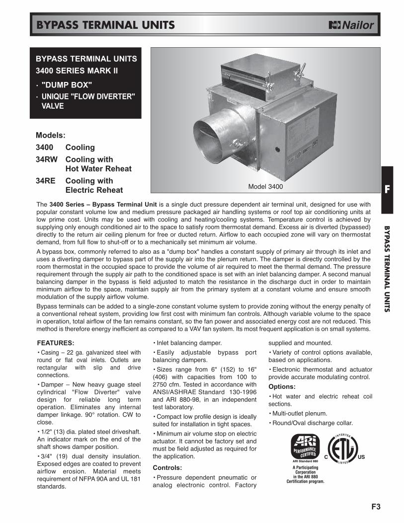
BYPASS TERMINAL UNITS3400 SERIES MARK II
• "DUMP BOX"• UNIQUE "FLOW DIVERTER"
VALVE
Model 3400
BYPASS TERMINAL UNITS
F
BY
PASS TER
MIN
AL U
NITS
FEATURES: • Casing – 22 ga. galvanized steel withround or flat oval inlets. Outlets arerectangular with slip and driveconnections.
• Damper – New heavy guage steelcylindrical "Flow Diverter" valvedesign for reliable long termoperation. Eliminates any internaldamper linkage. 90° rotation. CW toclose.
• 1/2" (13) dia. plated steel driveshaft.An indicator mark on the end of theshaft shows damper position.
• 3/4" (19) dual density insulation.Exposed edges are coated to preventairflow erosion. Material meetsrequirement of NFPA 90A and UL 181standards.
• Inlet balancing damper.
• Easily adjustable bypass portbalancing dampers.
• Sizes range from 6" (152) to 16"(406) with capacities from 100 to2750 cfm. Tested in accordance withANSI/ASHRAE Standard 130-1996and ARI 880-98, in an independenttest laboratory.
• Compact low profile design is ideallysuited for installation in tight spaces.
• Minimum air volume stop on electricactuator. It cannot be factory set andmust be field adjusted as required forthe application.
Controls:• Pressure dependent pneumatic oranalog electronic control. Factory
supplied and mounted.
• Variety of control options available,based on applications.
• Electronic thermostat and actuatorprovide accurate modulating control.
Options:• Hot water and electric reheat coilsections.
• Multi-outlet plenum.
• Round/Oval discharge collar.
The 3400 Series – Bypass Terminal Unit is a single duct pressure dependent air terminal unit, designed for use withpopular constant volume low and medium pressure packaged air handling systems or roof top air conditioning units atlow prime cost. Units may be used with cooling and heating/cooling systems. Temperature control is achieved bysupplying only enough conditioned air to the space to satisfy room thermostat demand. Excess air is diverted (bypassed)directly to the return air ceiling plenum for free or ducted return. Airflow to each occupied zone will vary on thermostatdemand, from full flow to shut-off or to a mechanically set minimum air volume.
A bypass box, commonly referred to also as a "dump box" handles a constant supply of primary air through its inlet anduses a diverting damper to bypass part of the supply air into the plenum return. The damper is directly controlled by theroom thermostat in the occupied space to provide the volume of air required to meet the thermal demand. The pressurerequirement through the supply air path to the conditioned space is set with an inlet balancing damper. A second manualbalancing damper in the bypass is field adjusted to match the resistance in the discharge duct in order to maintainminimum airflow to the space, maintain supply air from the primary system at a constant volume and ensure smoothmodulation of the supply airflow volume.
Bypass terminals can be added to a single-zone constant volume system to provide zoning without the energy penalty ofa conventional reheat system, providing low first cost with minimum fan controls. Although variable volume to the spacein operation, total airflow of the fan remains constant, so the fan power and associated energy cost are not reduced. Thismethod is therefore energy inefficient as compared to a VAV fan system. Its most frequent application is on small systems.
Models:3400 Cooling34RW Cooling with
Hot Water Reheat34RE Cooling with
Electric Reheat
A ParticipatingCorporation
in the ARI 880Certification program.

F4
BYPASS TERMINAL UNITS
F
BY
PASS
TER
MIN
AL
UN
ITS
Unique "Flow Diverter"ValveNailor's 3400 Series Mark II bypassterminal units utilize a unique cylindricalflow diverter valve for superior controland performance. A common problemwith standard pivoted single bladedamper designs is objectionable noiseand loss of modulation due to pulsatingand/or a snap-closing action of thevalve. This is caused by a poor valvedesign, which struggles to modulateturbulent airflow and requires excessivetorque.
The Nailor flow diverter valve eliminatesthese problems. The rugged cylindricaldamper design smoothly modulatesbetween supply and bypass conditionsand when installed under airflow isessentially self-balancing, requiring onlya negligible torque requirement. Theresult is superior reliable long-termperformance and quiet operation.
Electronic ModulatingControlsNailor offers a series of state of the artanalog electronic control packageswhich provide true modulating controland superior performance overconventional electric controls. Theseolder packages essentially provideon/off control of the bypass terminal.Commonly, the damper is driven to thefull supply or full bypass position beforea change in space temperature issensed by the room thermostat. Lowspeed actuators are often used to slowthe damper response, but result insluggish control and large swings in occupied space temperature which waste energy and provide poor comfort.
Nailor's electronic packages feature advanced microcomputer electronics and proportional plus integral (P + I) controlalgorithms to provide precise temperature control. The thermostat provides a true multi-position modulating output to aconventional 24 VAC tri-state floating actuator. The thermostat output cycles the actuator with shorter or longer "on times"proportional to the temperature offset, preventing temperature overshoot. The thermostat also tracks how long the roomtemperature has varied from set point and adjusts the output accordingly. This eliminates wasted energy caused bytypical on/off cycling with conventional SPDT thermostats, resulting in significant energy savings and superior comfort.Control deadband accuracy is +/- 0.4°F (+/- 0.2°C) around set point. When a reheat stage is required, the electronicthermostat provides a time proportioning on/off output signal based on a 15 minute duty cycle that proportionatelymodulates the reheat coil, adjusting the amount of "on time" in accordance with room temperature offset. This featureprovides performance similar to an SCR controller, but at a fraction of the cost.
BYPASS PORTWITH BALANCING
DAMPER
CONTROLSENCLOSURE
UNIQUE FLOWDIVERTER VALVE
DISCHARGE WITHSLIP AND DRIVE CONNECTION
INLETCOLLAR
WITHBALANCING
DAMPER
Options:• Thermostat Scale Plate °F or °C.• 24 VAC Control transformer. • Toggle disconnect switch.
F5
BYPASS TERMINAL UNITS
F
BY
PASS TER
MIN
AL U
NITS
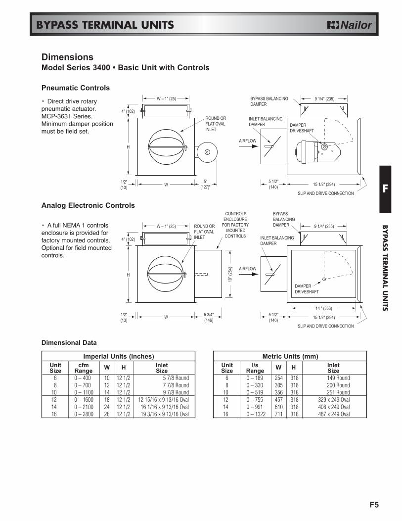
Imperial Units (inches)Unit cfm InletSize Range W H Size
6 0 – 400 10 12 1/2 5 7/8 Round8 0 – 700 12 12 1/2 7 7/8 Round
10 0 – 1100 14 12 1/2 9 7/8 Round12 0 – 1600 18 12 1/2 12 15/16 x 9 13/16 Oval14 0 – 2100 24 12 1/2 16 1/16 x 9 13/16 Oval16 0 – 2800 28 12 1/2 19 3/16 x 9 13/16 Oval
DimensionsModel Series 3400 • Basic Unit with Controls
Pneumatic Controls
Analog Electronic Controls
W 15 1/2" (394)
SLIP AND DRIVE CONNECTION
5"(127)"
5 1/2"(140)
1/2"(13)
HAIRFLOW
W
SLIP AND DRIVE CONNECTION
5 3/4"(146)
5 1/2"(140)
1/2"(13)
10" (
254)
H
15 1/2" (394)
AIRFLOW
CONTROLSENCLOSURE
FOR FACTORY MOUNTED
CONTROLS
W – 1" (25)
ROUND OR FLAT OVALINLET
4" (102)INLET BALANCINGDAMPER
BYPASS BALANCINGDAMPER
DAMPERDRIVESHAFT
W – 1" (25)
4" (102) INLET BALANCINGDAMPER
DAMPERDRIVESHAFT
14 " (356)
BYPASSBALANCINGDAMPER 9 1/4" (235)
9 1/4" (235)
ROUND OR FLAT OVALINLET
• Direct drive rotarypneumatic actuator.MCP-3631 Series.Minimum damper positionmust be field set.
• A full NEMA 1 controlsenclosure is provided forfactory mounted controls.Optional for field mountedcontrols.
Dimensional Data
Metric Units (mm)Unit l/s InletSize Range W H Size
6 0 – 189 254 318 149 Round8 0 – 330 305 318 200 Round
10 0 – 519 356 318 251 Round12 0 – 755 457 318 329 x 249 Oval14 0 – 991 610 318 408 x 249 Oval16 0 – 1322 711 318 487 x 249 Oval

F6
BYPASS TERMINAL UNITS
F
BY
PASS
TER
MIN
AL
UN
ITS
5 1/2"(140) 51 1/2" (1308) W
SLIP AND DRIVE CONNECTION
H
Integral Sound Attenuator
5 1/2"(140) 15 1/2" (394)
OPTIONALACCESS DOOR
L W
SLIP AND DRIVE CONNECTION
H H
Hot Water Reheat Coils
15" (381) MAX.63 1/2" (1613)
W
SLIP AND DRIVE CONNECTION
5 3/4"(146)
H
ELECTRIC COILCONTROLS
ENCLOSURE(HINGED
ACCESS DOOR)
5 1/2"(140)
AIRFLOWPRIMARY AIR VALVE
CONTROLS ENCLOSURE
Integral Electric Reheat
Dimensional DataImperial Units (inches)
Hot Water CoilUnit Size W H L (1 & 2 row) L (3 & 4 row)
6 10 12 1⁄2 5 7 1⁄28 12 12 1⁄2 5 7 1⁄2
10 14 12 1⁄2 5 7 1⁄212 18 12 1⁄2 5 7 1⁄214 24 12 1⁄2 5 7 1⁄216 28 12 1⁄2 5 7 1⁄2
• Single continuous lengthterminal construction minimizescasing leakage.• Continuous internalinsulation reduces insulationseams and minimizes airflowdisturbance.
• One and two row standard. Three andfour row available.• Hot water coils have copper tubes andaluminum ripple fins. Coils have 1/2"(13) or7/8" (22) O.D. sweat connections. Right orleft hand connection is determined bylooking through the terminal inlet in thedirection of airflow.• Galvanized steel casing with slip anddrive discharge duct connection.• Optional low leakage gasketed accessdoor is recommended for coil access andcleaning. Performance data on page F13.
• Electric coil is factorymounted in an integralextended plenumsection.• Full details andselection guide onpage F18.
5 1/2"(140) 51 1/2" (1308)
OPTIONAL ACCESS DOORW
SLIP AND DRIVE CONNECTION
H H
L
Integral Attenuator plus Hot Water Coil• All the benefits ofboth the Integral SoundAttenuator and the HotWater Coils shownabove in one.• Performance data onpage F13.
DimensionsModel Series 3400 • Bypass Terminal Unit Accessories
Metric Units (mm)Hot Water Coil
Unit Size W H L (1 & 2 row) L (3 & 4 row)6 254 318 127 1918 305 318 127 191
10 356 318 127 19112 457 318 127 19114 610 318 127 19116 711 318 127 191
F7
BYPASS TERMINAL UNITS
F
BY
PASS TER
MIN
AL U
NITS
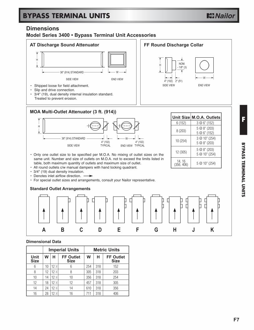
DimensionsModel Series 3400 • Bypass Terminal Unit Accessories
AT Discharge Sound Attenuator
MOA Multi-Outlet Attenuator (3 ft. (914))
Standard Outlet Arrangements
Dimensional Data
FF Round Discharge Collar
H
36" (914) STANDARD W
END VIEWSIDE VIEW
H
36" (914) STANDARD
SIDE VIEW4" (102)
TYPICAL4" (102)
TYPICAL
W
END VIEW
A B C D E F G H J K
4" (102)
H
END VIEW
NOM.- 1/8" (3)
2" (51)W
SIDE VIEW
Unit Size M.O.A. Outlets6 (152) 3 @ 6" (152)
8 (203)5 @ 8" (203)5 @ 6" (152)
10 (254)3 @ 10" (254)5 @ 8" (203)
12 (305)5 @ 8" (203)5 @ 10" (254)
14, 16(356, 406) 5 @ 10" (254)
Imperial Units Metric UnitsUnit W H FF Outlet W H FF OutletSize Size Size
6 10 12 1⁄2 6 254 318 1528 12 12 1⁄2 8 305 318 20310 14 12 1⁄2 10 356 318 25412 18 12 1⁄2 12 457 318 30514 24 12 1⁄2 14 610 318 35616 28 12 1⁄2 16 711 318 406
• Shipped loose for field attachment.• Slip and drive connection.• 3/4" (19), dual density internal insulation standard.
Treated to prevent erosion.
• Only one outlet size to be specified per M.O.A. No mixing of outlet sizes on thesame unit. Number and size of outlets on M.O.A. not to exceed the limits listed intable, both maximum quantity of outlets and maximum size of outlet.
• All round outlets c/w manual dampers with hand locking quadrant.• 3/4" (19) dual density insulation.• Denotes inlet airflow direction.• For special outlet sizes and arrangements, consult your Nailor representative.

Min. Min. NC Levels
Inlet AirflowDischarge Bypass
DischargeRadiated
ΔPs ΔPs Bypass BypassSizecfm l/s "w.g. Pa "w.g. Pa Closed Open400 189 0.01 2 0.14 35 - - 25
6300 142 0.01 2 0.08 20 - - -200 94 0.01 2 0.04 10 - - -100 47 0.01 2 0.01 2 - - -700 330 0.01 2 0.21 52 - - 30
8500 236 0.01 2 0.11 27 - - 20350 165 0.01 2 0.05 12 - - -200 94 0.01 2 0.02 5 - - -
1100 519 0.01 2 0.43 107 - 20 37
10800 378 0.01 2 0.23 57 - - 25500 236 0.01 2 0.09 22 - - -250 118 0.01 2 0.02 5 - - -
1600 755 0.01 2 0.50 124 - 20 40
121200 566 0.01 2 0.28 70 - - 33800 378 0.01 2 0.13 32 - - 22400 189 0.01 2 0.03 7 - - -
2100 991 0.05 12 0.50 124 - 31 43
141600 755 0.03 7 0.29 72 - 24 351050 495 0.01 2 0.12 30 - - 23550 260 0.01 2 0.03 7 - - -
2750 1298 0.06 15 0.50 124 21 34 47
162050 967 0.03 7 0.28 70 - 24 371375 649 0.01 2 0.13 32 - - 27700 330 0.01 2 0.03 7 - - -
F8
BYPASS TERMINAL UNITS
F
BY
PASS
TER
MIN
AL
UN
ITS
Performance Notes:1. NC levels are calculated fromthe published raw data and basedon procedures outlined inAppendix E, ARI 885-98.
2. Discharge sound attenuationdeductions are based onenvironmental effect, duct lining,branch power division, insulatedflex duct, end reflection and spaceeffect and are as follows:
3. Radiated sound attenuationdeductions are based on a mineraltile ceiling and environmentaleffect and are as follows:
4. Minimum discharge ΔPs is thestatic pressure loss through theunit with 100% airflow throughdischarge outlet.
5. Minimum bypass ΔPs is thestatic pressure loss through theunit with 100% airflow through thebypass outlet.6. Dash (–) in space denotes anNC level of less than 20.7. For a complete explanation anddetails on NC calculations, refer topage B9 and the engineeringsection of this catalog.
Model Series 3400Performance Data • NC Level Application Guide
< 300 cfm 24 28 39 53 58 40300 – 700 cfm 27 29 40 51 53 39
> 700 cfm 29 30 41 51 52 39
Discharge attenuationOctave Band
2 3 4 5 6 7
Total dB reduction 18 19 20 26 31 36
Radiated attenuationOctave Band
2 3 4 5 6 7

Min. Min. Sound Power Octave Bands
Inlet Airflow Discharge Bypass RadiatedΔPs ΔPs Discharge Bypass Closed Bypass OpenSize
cfm l/s "w.g. Pa "w.g. Pa 2 3 4 5 6 7 2 3 4 5 6 7 2 3 4 5 6 7400 189 0.01 2 0.14 35 45 44 41 33 29 26 42 37 33 24 20 20 54 55 52 52 51 37
6300 142 0.01 2 0.08 20 43 38 34 25 - - - 34 25 - - - 47 48 45 47 37 26200 94 0.01 2 0.04 10 - 31 24 - - - - - - - - - - 38 34 32 - -100 47 0.01 2 0.01 2 - - - - - - - - - - - - - 34 29 - - -700 330 0.01 2 0.21 52 52 51 47 39 36 33 47 41 34 28 26 20 60 59 55 53 48 41
8500 236 0.01 2 0.11 27 45 43 38 29 24 - 43 34 27 - - - 52 50 46 43 3 28350 165 0.01 2 0.05 12 - 34 28 - - - - 32 - - - - 47 40 37 32 25 -200 94 0.01 2 0.02 5 - - - - - - - - - - - - 43 30 - - - -
1100 519 0.01 2 0.43 107 50 50 46 43 37 34 52 49 46 37 32 23 65 64 62 60 56 52
10800 378 0.01 2 0.23 57 47 47 36 30 28 22 49 43 39 28 26 - 56 55 52 50 46 41500 236 0.01 2 0.09 22 44 40 34 28 - - 43 35 29 - - - 47 45 43 41 34 -250 118 0.01 2 0.02 5 40 30 - - - - - - - - - - 42 28 - - - -
1600 755 0.01 2 0.50 124 49 47 45 43 44 40 48 51 47 37 35 29 69 69 66 63 60 56
121200 566 0.01 2 0.28 70 44 40 38 36 36 29 43 41 38 29 25 - 61 60 58 56 52 46800 378 0.01 2 0.13 32 40 31 25 - - - 40 33 29 - - - 50 49 49 46 39 31400 189 0.01 2 0.03 7 - - 26 - - - - - 25 - - - 44 40 41 35 28 -
2100 991 0.05 12 0.50 124 60 57 54 48 45 36 54 58 56 49 49 41 69 69 67 65 61 57
141600 755 0.03 7 0.29 72 54 49 44 39 34 24 48 50 49 42 40 29 62 62 60 57 53 481050 495 0.01 2 0.12 30 47 37 31 24 - - 44 40 38 29 - - 51 50 50 45 40 31550 260 0.01 2 0.03 7 - 31 - - - - - 31 26 - - - - 37 36 29 - -
2750 1298 0.06 15 0.50 124 66 64 61 56 52 46 64 63 59 49 46 37 73 73 71 69 65 61
162050 967 0.03 7 0.28 70 58 56 51 46 42 34 57 54 50 41 36 25 65 65 63 61 56 501375 649 0.01 2 0.13 32 50 45 39 33 27 - 45 41 38 27 - - 54 53 53 50 44 34700 330 0.01 2 0.03 7 47 31 - - - - - - - - - - 40 35 33 25 - -
F9
BYPASS TERMINAL UNITS
F
BY
PASS TER
MIN
AL U
NITS
Model Series 3400Performance Data • Sound Power Levels
Performance Notes:1.Discharge sound power is thenoise emitted from the unitdischarge into the downstream duct.
2.Radiated sound power is thebreakout noise transmitted throughthe unit casing walls.
3.Sound power levels are indecibels, dB re 10-12 watts.
4.All sound data listed by octavebands is raw data without anycorrections for room absorption orduct attenuation. Dash (-) in spaceindicates sound power level is lessthan 20 or equal to background.
5.Minimum discharge ΔPs is thestatic pressure loss through the unitwith 100% airflow through dischargeoutlet.
6.Minimum bypass ΔPs is the staticpressure loss through the unit with100% airflow through the bypassoutlet.
7.Data derived from tests conductedin accordance with ANSI/ASHRAEStd. 130-1996 and ARI Standard880-98.
Min. Inlet Sound Power Octave BandsInlet Airflow ΔPs Discharge RadiatedSize
cfm l/s "w.g. Pa 2 3 4 5 6 7 2 3 4 5 6 76 400 189 0.01 2 45 44 41 33 29 26 42 37 33 24 20 208 700 330 0.01 2 52 51 47 39 36 33 47 41 34 28 26 2010 1100 519 0.01 2 50 50 46 43 37 34 52 49 46 37 32 2312 1600 755 0.01 2 49 47 45 43 44 40 48 51 47 37 35 2914 2100 991 0.05 12 60 57 54 48 45 36 54 58 56 49 49 4116 2750 1298 0.06 15 66 64 61 56 52 46 64 63 59 49 46 37
ARI Certification Rating Points
A ParticipatingCorporation
in the ARI 880Certification program.

F10
BYPASS TERMINAL UNITS
F
BY
PASS
TER
MIN
AL
UN
ITS
Control Sequence P1Cooling (with Optional Reheat) • Reverse Acting/NormallyOpen• When main control air is off, damper is fully open and the bypass isclosed.• When main control air is on, cooling airflow modulates according tothermostat output.• On a rise in room temperature, the thermostat line pressure to theactuator decreases. The actuator moves the damper to the openposition, increasing the cooling airflow to the room, closing the bypassair at the same time.• If the room thermostat is satisfied before the damper is fully open, thedamper remains in a modulated position until further demand.• On a fall in room temperature, the thermostat line pressure increases,moving the actuator to close the damper and decreases the coolingairflow to the room. At the same time, supply air is diverted through thebypass port into the plenum.• A mechanical minimum stop requires field setting.• An optional hot water coil valve or electric heater may be sequencedfor reheat applications (8 – 13 psi). Hot water valve is supplied byothers. P.E. switch is included in electric heater.
MECHMIN. STOP
20
0
% F
LOW
THERMOSTAT BRANCH PRESSURE (PSI)ROOM TEMPERATURE INCREASE
40
60
80
100
3 5 8 10 13 15
8 – 13 PSI PNEUMATIC ACTUATOR IS STANDARD.MODEL MCP-3631-5000
OPTIONAL REHEATAIRFLO
W
MECH.MIN. STOP
20
0
% F
LOW
THERMOSTAT BRANCH PRESSURE (PSI)ROOM TEMPERATURE DECREASE
40
60
80
100
3 5 8 10 13 15
OPTIONAL R
EHEATAIRFLOW
3 – 8 PSI PNEUMATIC ACTUATOR IS STANDARD.MODEL MCP-3631-8000
Standard Control SequencesPneumatic • Pressure DependentA variety of popular sequences are illustrated to suit most applications. For non-standard or other specific applications,contact your Nailor representative.
Control Sequence Package P1ACooling (with Optional Reheat) • Direct Acting/NormallyClosed• When main control air is off, damper is fully closed and the bypass isopen.
• When main control air is on, cooling airflow modulates according tothermostat output.
• On a rise in room temperature, the thermostat line pressure to theactuator increases. The actuator moves the damper to the openposition, increasing the cooling airflow to the room, closing the bypassair at the same time.
• If the room thermostat is satisfied before the damper is fully open, thedamper remains in a modulated position until further demand.
• On a fall in room temperature, the thermostat line pressuredecreases, moving the actuator to close the damper and decreases thecooling airflow to the room. At the same time, supply air is divertedthrough the bypass port into the plenum.
• A mechanical minimum stop requires field setting.
• An optional hot water coil valve or electric heater may be sequencedfor reheat applications (3 – 8 psi). Hot water valve is supplied by others.P.E. switch is included in electric heater.

F11
BYPASS TERMINAL UNITS
F
BY
PASS TER
MIN
AL U
NITS
DAMPEROPEN
DAMPEROPEN
COO
LING
HEATING
% O
PEN
DAMPERCLOSED
(MIN.)
100
80
60
40
20
0AI
RFLO
W IN
CREA
SE
DIALSET POINT
CENTERED INDEAD BAND2°F (1.1°C)
HEATING SET
POINT
COOLING SET
POINT
ROOM TEMPERATURE INCREASE
SETPOINT
DAMPEROPEN
COO
LING
% O
PEN
DAMPERCLOSED
(MIN.)
100
80
60
40
20
0
AIRF
LOW
INCR
EASE
ROOM TEMPERATURE INCREASE
SETPOINT
Control Sequence E2Cooling OnlyCentral system supplies cool air. On a rise in room temperature above setpoint, the bypass damper will slowly modulate open, increasing the flow of airto the room, closing the bypass at the same time. On a fall in room temperaturebelow set point, the bypass damper will modulate closed, reducing the flow ofcool air into the room and opening the bypass at the same time. A mechanicalair volume minimum stop is provided (field set).
DAMPEROPEN
ON
COO
LING
REHEAT
% O
PEN
DAMPERCLOSED
(MIN.)
100
80
60
40
20
0
AIRF
LOW
INCR
EASE
DIAL SET POINTCENTERED INDEAD BAND2°F (1.1°C)
OFF
HEATING SET
POINT
COOLING SET
POINT
ROOM TEMPERATURE INCREASE
SETPOINT
Standard Control SequencesAnalog Electronic • Pressure Dependent
Model 3400 or 34RW
Model 3400
Model 3400
Control Sequence E3Automatic Heating/Cooling ChangeoverThis arrangement is for systems supplying cool air in summer and hot air inwinter. A duct temperature sensor senses inlet temperature and automaticallyreverses control action when supply air is above 78°F (26°C). A mechanical airvolume minimum stop is provided (field set).
Cooling Mode:Supply air system in cooling mode (below 75°F (24°C)). On a rise in roomtemperature above set point, the bypass damper will modulate open,increasing the flow of cool air to the room, closing the bypass at the same time.On a fall in room temperature below set point, the bypass damper will modulateclosed, reducing the flow of cool air into the room and opening the bypass atthe same time.
Heating Mode:Supply air system in heating mode (above 78°F (26°C)). On a rise in roomtemperature above set point, the bypass damper will modulate closed,reducing the flow of warm air into the room to maintain set point and openingthe bypass. On a fall in room temperature below set point, the bypass damperwill modulate open, increasing the flow of warm air into the room to maintainthe set point and closing the bypass at the same time.
Control Sequence E4Cooling with Auxiliary Heat (Perimeter Heating or Hot Water Reheat)Central system supplies cool air. On a rise in room temperature above setpoint, the bypass damper will slowly modulate open, increasing the flow of airto the room, closing the bypass at the same time. On a fall in room temperaturebelow set point, the bypass damper will modulate closed, reducing the flow ofcool air into the room and opening the bypass at the same time.If room temperature continues to fall, the thermostat will energize the controlrelay/valve of the perimeter heating or hot water valve for reheat. A mechanicalair volume minimum stop is provided (field set).

F12
BYPASS TERMINAL UNITS
F
BY
PASS
TER
MIN
AL
UN
ITS
DAMPEROPEN
ON
COO
LING
REHEAT
% O
PEN
DAMPERCLOSED
(MIN.)
100
80
60
40
20
0
AIRF
LOW
INCR
EASE
DIAL SET POINTCENTERED INDEAD BAND2°F (1.1°C)
OFF
HEATING SET
POINT
COOLING SET
POINT
ROOM TEMPERATURE INCREASE
SETPOINT
Standard Control SequencesAnalog Electronic • Pressure Dependent
Control Sequence E4Cooling with One Stage Electric HeatCentral system supplies cool air. On a rise in room temperature above set point,the bypass damper will slowly modulate open, increasing the flow of air to theroom, closing the bypass at the same time. On a fall in room temperature belowset point, the bypass damper will modulate closed, reducing the flow of cool airinto the room and opening the bypass at the same time.If room temperature continues to fall, the thermostat will energize the controlrelay of the electric reheat coil.Note: When an electric duct reheat coil is used, the adjustable mechanical endstop on the actuator must be field set to ensure sufficient airflow over theheating coil [70 cfm (33 l/s) per kW minimum].
Control Sequence E5Automatic Heating/Cooling Changeover with Auxiliary Heat (PerimeterHeating or Hot Water Heat)This arrangement is for systems supplying cool air in summer and hot air inwinter. A duct temperature sensor senses inlet temperature and automaticallyreverses control action when supply air is above 78°F (26°C). A mechanical airvolume minimum stop is provided (field set).
Cooling Mode:Supply air system in cooling mode (below 75°F (24°C)). On a rise in roomtemperature above set point, the bypass damper will modulate open, increasingthe flow of cool air to the room, closing the bypass at the same time. On a fall inroom temperature below set point, the bypass damper will modulate closed,reducing the flow of cool air into the room and opening the bypass at the sametime. If room temperature continues to fall, the thermostat will energize thecontrol relay/valve of the perimeter heating or hot water reheat valve for reheat.
Heating Mode:Supply air system in heating mode (above 78°F (26°C)). On a rise in room temperature above set point, the bypassdamper will modulate closed, reducing the flow of warm air into the room to maintain set point and opening the bypass.On a fall in room temperature below set point, the bypass damper will modulate open, increasing the flow of warm airinto the room to maintain the set point and closing the bypass at the same time. If room temperature continues to fall,the thermostat will energize control relay/valve of the perimeter heating or the hot water valve for supplementary heat.
Control Sequence E5Automatic Heating/Cooling Changeover with One Stage Electric HeatThis arrangement is for systems supplying cool air in summer and hot air inwinter. A duct temperature sensor senses inlet temperature and automaticallyreverses control action when supply air is above 78°F (26°C).
Cooling Mode:Supply air system in cooling mode (below 75°F (24°C)). On a rise in roomtemperature above set point, the bypass damper will modulate open, increasingthe flow of cool air to the room, closing the bypass at the same time. On a fallin room temperature below set point, the bypass damper will modulate closed,reducing the flow of cool air into the room and opening the bypass at the sametime. If room temperature continues to fall, the electric heat is energized.
Heating Mode:Supply air system in heating mode (above 78°F (26°C)). On a rise in roomtemperature above set point, the bypass damper will modulate closed,decreasing the flow of cool air to the room and opening the bypass at the same time. On a fall in room temperaturebelow set point, the bypass damper will modulate open, increasing the flow of warm air into the room and closing thebypass at the same time. If room temperature continues to fall, the electric heat is energized.Note: The mechanical minimum stop must be field set to ensure sufficient airflow over the heating coil [70 cfm (33 l/s)per kW minimum].
DAMPEROPEN
DAMPEROPEN
COO
LING
HEATING
ON PERIMETER HEAT O
R HOT WATER REHEAT
% O
PEN
DAMPERCLOSED
(MIN.)
100
80
60
40
20
0AI
RFLO
W IN
CREA
SE
DIALSET POINT
CENTERED INDEAD BAND2°F (1.1°C)
OFF
HEATING SET
POINT
COOLING SET
POINT
ROOM TEMPERATURE INCREASE
SETPOINT
Model 34RE
Model 3400 or 34RW
DAMPEROPEN
DAMPEROPEN
COO
LING
HEATING
ON
REHEAT
% O
PEN
DAMPERCLOSED
(MIN.)
100
80
60
40
20
0
AIRF
LOW
INCR
EASE
DIALSET POINT
CENTERED INDEAD BAND2°F (1.1°C)
OFF
HEATING SET
POINT
COOLING SET
POINT
ROOM TEMPERATURE INCREASE
SETPOINT
Model 3400 or 34RE

F13
BYPASS TERMINAL UNITS
F
BY
PASS TER
MIN
AL U
NITS
Unit Size 6
Performance DataHot Water Coil • Mbh CapacitiesModel 34RW
2 Row (multi-circuit)
CFM
17
15
13
11
9
7
5
3
50 100 150 200 250 300 350 400 450 500
3 GPM2 GPM1.5 GPM
1 GPM
0.5 GPM
MBH
1 Row (single circuit)
1 Row (single circuit) 2 Row (multi-circuit)
CFM
28
25
22
19
16
13
10
7
450 100 150 200 250 300 350 400 450 500
3 GPM
2 GPM
1.5 GPM
1 GPM
0.5 GPMMBH
Notes:1. Capacities are in Mbh (thousands of Btuper hour).
2. Mbh values are based on a Δt(temperature difference) of 125°F betweenentering air and entering water. For otherΔt's; multiply the Mbh values by the factorsbelow.
3. Air Temperature Rise. ATR = 927 x Mbh
cfm
4. Water Temp. Drop. WTD = 2.04 x Mbh
GPM
5. Connections: 1 Row 1/2"(13), 2 Row 7/8"(22); O.D. male solder.
Altitude Sensible Heat(ft.) Factor
0 1.002000 0.943000 0.904000 0.875000 0.846000 0.817000 0.78
Altitude Correction Factors:
Correction factors at other entering conditions:t °F 40 50 60 70 80 90 100 110 125 140 160 180
FACTOR 0.32 0.40 0.48 0.56 0.64 0.72 0.80 0.88 1.00 1.12 1.28 1.44
7
9
11
13
15
17
19
21
23
25
200 300 400 500 600 700 800 900 1000CFM
MBH
5 GPM4 GPM3 GPM
2 GPM
1.5 GPM
1 GPM
0.5 GPM
11
14
17
20
23
26
29
32
35
38
41
44
200 300 400 500 600 700 800 900 1000CFM
MBH
5 GPM4 GPM
3 GPM
2 GPM
1.5 GPM
1 GPM
0.5 GPM
Unit Size 8

F14
BYPASS TERMINAL UNITS
F
BY
PASS
TER
MIN
AL
UN
ITS
Unit Size 10
Performance DataHot Water Coil • Mbh CapacitiesModel 34RW
2 Row (multi-circuit)1 Row (single circuit)
1 Row (single circuit) 2 Row (multi-circuit)
Notes:1. Capacities are in Mbh (thousands of Btuper hour).
2. Mbh values are based on a Δt(temperature difference) of 125°F betweenentering air and entering water. For otherΔt's; multiply the Mbh values by the factorsbelow.
3. Air Temperature Rise. ATR = 927 x Mbh
cfm
4. Water Temp. Drop. WTD = 2.04 x Mbh
GPM
5. Connections: 1 Row 1/2" (13), 2 Row7/8" (22); O.D. male solder.
Altitude Sensible Heat(ft.) Factor
0 1.002000 0.943000 0.904000 0.875000 0.846000 0.817000 0.78
Altitude Correction Factors:
Correction factors at other entering conditions:t °F 40 50 60 70 80 90 100 110 125 140 160 180
FACTOR 0.32 0.40 0.48 0.56 0.64 0.72 0.80 0.88 1.00 1.12 1.28 1.44
Unit Size 12
8
11
14
17
20
23
26
29
32
300 400 500 600 700 800 900 1000 1100 1200 1300 1400CFM
MBH
7.5 GPM5 GPM
3 GPM
2 GPM
1 GPM
0.5 GPM
14
18
22
26
30
34
38
42
46
50
54
58
300 400 500 600 700 800 900 1000 1100 1200 1300 1400CFM
MBH
7.5 GPM
5 GPM
3 GPM
2 GPM
1 GPM
0.5 GPM
12
16
20
24
28
32
36
40
44
400 550 700 850 1000 1150 1300 1450 1600 1750 1900 2050 2200CFM
MBH
10 GPM7.5 GPM5 GPM
3 GPM
2 GPM
1 GPM
22
27
32
37
42
47
52
57
62
67
72
77
82
400 550 700 850 1000 1150 1300 1450 1600 1750 1900 2050 2200CFM
MBH
10 GPM7.5 GPM
5 GPM
3 GPM
2 GPM
1 GPM

F15
BYPASS TERMINAL UNITS
F
BY
PASS TER
MIN
AL U
NITS
Unit Size 14
Performance DataHot Water Coil • Mbh CapacitiesModel 34RW
2 Row (multi-circuit)1 Row (single circuit)
1 Row (single circuit) 2 Row (multi-circuit)
Notes:1. Capacities are in Mbh (thousands of Btuper hour).
2. Mbh values are based on a Δt(temperature difference) of 125°F betweenentering air and entering water. For otherΔt's; multiply the Mbh values by the factorsbelow.
3. Air Temperature Rise. ATR = 927 x Mbh
cfm
4. Water Temp. Drop. WTD = 2.04 x Mbh
GPM
5. Connections: Size 14 – 1 Row 1/2" (13),all others – 7/8" (22); O.D. male solder.
Altitude Sensible Heat(ft.) Factor
0 1.002000 0.943000 0.904000 0.875000 0.846000 0.817000 0.78
Altitude Correction Factors:
Correction factors at other entering conditions:t °F 40 50 60 70 80 90 100 110 125 140 160 180
FACTOR 0.32 0.40 0.48 0.56 0.64 0.72 0.80 0.88 1.00 1.12 1.28 1.44
Unit Size 16
17
21
25
29
33
37
41
45
49
53
57
500 700 900 1100 1300 1500 1700 1900 2100 2300 2500 2700CFM
MBH
10 GPM7.5 GPM5 GPM
3 GPM
2 GPM
1 GPM
28
33
38
43
48
53
58
63
68
73
78
83
88
93
98
103
500 700 900 1100 1300 1500 1700 1900 2100 2300 2500 2700CFM
MBH
10 GPM7.5 GPM
5 GPM
3 GPM
2 GPM
1 GPM
20
26
32
38
44
50
56
62
68
700 950 1200 1450 1700 1950 2200 2450 2700 2950 3200 3450 3700CFM
MBH
10 GPM7.5 GPM
5 GPM
3 GPM
2 GPM
1 GPM
29
37
45
53
61
69
77
85
93
101
109
117
125
700 950 1200 1450 1700 1950 2200 2450 2700 2950 3200 3450 3700CFM
MBH
10 GPM
7.5 GPM
5 GPM
3 GPM
2 GPM
1 GPM

F16
BYPASS TERMINAL UNITS
F
BY
PASS
TER
MIN
AL
UN
ITS
Performance DataHot Water Coil • Pressure DropsModel 34RW
Air Pressure DropWater Pressure Drop
WATER FLOW, GPM AIRFLOW, CFM
HEA
D L
OSS
(WAT
ER P
RES
SUR
E D
RO
P), F
T. W
ATER
AIR
PR
ESSU
RE
DR
OP,
INC
HES
W.G
.
Air Pressure DropWater Pressure Drop
AIR
PR
ESSU
RE
DR
OP,
INC
HES
W.G
.
Air Pressure DropWater Pressure Drop
AIRFLOW, CFM
AIR
PR
ESSU
RE
DR
OP,
INC
HES
W.G
.
Air Pressure DropWater Pressure Drop
AIRFLOW, CFM
AIR
PR
ESSU
RE
DR
OP,
INC
HES
W.G
.
Unit Size 6 Unit Size 8
Unit Size 10 Unit Size 12
1 2 3 4 6 8 10 100 200 300 500
AIRFLOW, CFM
100 200 400 600 800 1000
1 ROW
2 ROW
1 ROW
2 ROW
10.0
8.0
6.0
4.0
2.0
1.0
0.80.6
0.4
0.2
0.1
1.00
0.80
0.60
0.40
0.200.10
0.08
0.06
0.04
0.020.01
WATER FLOW, GPM
HEA
D L
OSS
(WAT
ER P
RES
SUR
E D
RO
P), F
T. W
ATER
10.0
8.0
6.0
4.0
2.0
1.0
0.8
0.6
0.4
0.2
0.1
WATER FLOW, GPM
HEA
D L
OSS
(WAT
ER P
RES
SUR
E D
RO
P), F
T. W
ATER
1 2 3 4 6 8 10
8.0
6.0
4.0
2.0
1.00.8
0.6
0.4
0.2
0.1
WATER FLOW, GPM
HEA
D L
OSS
(WAT
ER P
RES
SUR
E D
RO
P), F
T. W
ATER
1 2 3 4 6 8 10
10.0
8.0
6.0
4.0
2.0
1.0
0.80.6
0.4
0.2
0.1
1.00
0.80
0.60
0.40
0.200.10
0.08
0.06
0.04
0.020.01
10.08.0
6.0
4.0
2.01.00.8
0.6
0.4
0.20.1
0.08
0.06
0.04
0.020.01
1 2 3 4 6 8 10
100 200 400 600 1000 2000 100 200 400 600 1000 2000 3000
1 ROW
2 ROW
1 ROW
2 ROW
1 ROW
1 ROW
2 ROW
1 ROW
2 ROW
1 ROW
2 ROW
10.0 10.08.0
6.0
4.0
2.01.00.8
0.6
0.4
0.20.1
0.08
0.06
0.04
0.020.01
Metric Conversion Factors:1. Water Flow (liters per second)
l/s = gpm x 0.6309
2. Water Head Loss (kilopascals):
kPa = ft. w.g. x 2.9837
3. Airflow Volume (liters per second)
l/s = cfm x 0.472
4. Air Pressure Drop (Pascals):
Pa = in. w.g. x 248.6
5. Heat (kilowatts):
kW = Mbh x 0.293
2 ROW

F17
BYPASS TERMINAL UNITS
F
BY
PASS TER
MIN
AL U
NITS
Performance DataHot Water Coil • Pressure DropsModel 34RW
Air Pressure DropWater Pressure Drop
WATER FLOW, GPM AIRFLOW, CFM
HEA
D L
OSS
(WAT
ER P
RES
SUR
E D
RO
P), F
T. W
ATER
AIR
PR
ESSU
RE
DR
OP,
INC
HES
W.G
.
Air Pressure DropWater Pressure DropUnit Size 14 Unit Size 16
1 2 3 4 6 8 10 100 200 400 600 1000 2000 3000
AIRFLOW, CFM
100 200 400 600 1000 2000 4000
1 ROW
2 ROW
1 ROW
2 ROW
10.08.0
6.0
4.0
2.0
1.0
0.80.6
0.4
0.2
0.1
WATER FLOW, GPM
HEA
D L
OSS
(WAT
ER P
RES
SUR
E D
RO
P), F
T. W
ATER
10.0
8.0
6.0
4.0
2.0
1.0
0.80.6
0.4
0.2
0.1
1 2 3 4 6 8 10
1 ROW
2 ROW
1 ROW
2 ROW
10.08.0
6.0
4.0
2.01.00.8
0.6
0.4
0.20.1
0.080.06
0.04
0.02
0.01
10.08.06.0
4.0
2.01.00.8
0.6
0.4
0.20.1
0.080.06
0.04
0.020.01
Metric Conversion Factors:1. Water Flow (liters per second)
l/s = gpm x 0.6309
2. Water Head Loss (kilopascals):
kPa = ft. w.g. x 2.9837
3. Airflow Volume (liters per second)
l/s = cfm x 0.472
4. Air Pressure Drop (Pascals):
Pa = in. w.g. x 248.6
5. Heat (kilowatts):
kW = Mbh x 0.293A
IR P
RES
SUR
E D
RO
P, IN
CH
ES W
.G.

F18
BYPASS TERMINAL UNITS
F
BY
PASS
TER
MIN
AL
UN
ITS
Electric Heating Coils • Selection and CapacitiesNailor manufactures its own electric heating coils. Electricheater element racks are enclosed in an insulatedattenuator section which is shipped attached to the airterminal unit discharge. The location of the heaterelements in the attenuator downstream of the air terminalprovides adequate distance for the flow of supply air toexpand once past the damper so that there are no hotspots in the heater.
For dimensional data, see page F6.
Standard Features:• Primary auto-reset high limit thermal cut-out (one per coilin control circuit).• Secondary manual reset high limit thermal cut-outs (oneper element).• Positive pressure airflow switch.• Derated high quality nickel-chrome alloy heatingelements.• Magnetic or safety contactors and/or PE switches asrequired.• Line terminal block.• ETL Listed.• Hinged door control enclosure.• High performance arrowhead insulators.• Slip and drive discharge connection.
Selection:The adjacent table provides a general guideline as to thevoltages and kilowatt range available for each terminalunit size.
Maximum kilowatt loading is 1 kW per 70 cfm (33 l/s) atheating condition.
A good design will hold the discharge temperaturebetween 90 and 105°F (32 to 40.5°C). Never select kW toexceed a discharge temperature of 120°F (49°C)maximum for comfort heating.
Δt (air temp. rise, °F) = kW x 3160cfm
The coil ranges listed are restricted to a maximum of 48amps and do not require circuit fusing to meet NEC coderequirements. Total pressure at the airflow switch shouldbe at least 0.07" w.g. (17 Pa) to ensure correct coiloperation and prevent cut-out due to insufficient airflowover the coil elements.
Options:• Class 2, 24V control transformer.• Mercury contactors.• Toggle type disconnect switch.• Door interlock disconnect switch.• Power circuit fusing.• Dust tight construction.• SCR control.• Class 'A' 80/20 wire.
Electric Coil LimitationsVoltage/ kWPhase Range120/1 0.5 – 5.7
208/1 0.5 – 9.9
240/1 0.5 – 11.5
277/1 0.5 – 13.0
480/1 0.5 – 18.0
208/3 0.5 – 17.3
240/3 0.5 – 20.0
480/3 0.5 – 20.8
600/3 0.5 – 26.0

F19
BYPASS TERMINAL UNITS
F
BY
PASS TER
MIN
AL U
NITS
BYPASSBALANCING DAMPERS
INLETBALANCING
DAMPERFLOWDIVERTERVALVE
DAMPER ACTUATORFIELD ADJUST FOR MINIMUMAIR VOLUME IF REQUIRED
SUPPLY
AIRFLOW
HI.(Ps)
MAGNEHELICGAUGE
OUTLET BALANCING DAMPERAT TAKE-OFF
DISCHARGE
AIRFLOW
This balancing procedure assumes that the fan supplyingthe system maintains a constant static pressure in thesupply duct to the terminal unit. Bypass terminal units arepressure dependent and will need rebalancing if systemduct static pressure changes.
The 3400 series are shipped with both inlet and bypassbalancing dampers as standard to permit ease of field balancingand to ensure accurate adjustment and optimum operation.
1. Fully open the dampers of all supply outlets on thedischarge duct from the terminal unit.
2. Place terminal in the full open position, supplying100% air to the occupied space by adjusting thethermostat to full cooling.
3. Adjust the balancing damper located in the terminalinlet to provide the required total airflow.
4. Starting with the outlet furthest downstream, adjust thedamper of each air outlet to the required air volume.
5. Take a static pressure reading at the terminal unit afterthe inlet damper, using a magnehelic gauge or equivalent.
6. Adjust the room thermostat to full heating to provide100% bypass airflow or the minimum air volume to theroom, if a mechanical minimum air volume stop is utilized.An indicator mark on the end of the driveshaft showsdamper position, 90° rotation CW to close.
7. Adjust the bypass outlet damper(s) on the terminal untilthe static pressure reading equals that obtained in step 5.
8. Re-adjust the room thermostat to the desired setpointtemperature. The terminal is now balanced.
Mechanical Minimum Stop Field SettingProcedurePneumatic Actuator (MCP-3631 Series)Actuator rotation is 100°. Angleof rotation can be limited byinserting a 1/4" – 20 stroke stopscrew into front end of actuatorand securing with a lock nut(field supplied by user). Lengthof screw is unimportant as longas it has adequate threadlength. Damper rotates 90°,CW to close and has built in end stops.
1. Direct acting/normally closed damper connection:Disconnect control air to actuator. Ensure damper andactuator are in alignment. Damper should be fully closed.
(a) Using mechanical minimum stop. Adjust screw toback-off damper to required minimum airflow position.
(b) Using damper end stops (no mech. minimum stopprovided). Loosen collar set and bushing on dampershaft. Rotate damper shaft CCW to desired minimumairflow position and re-tighten actuator connection.
2. Reverse acting/normally open damper connection:
(a) Using stroke stop screw. Apply 20 psi main air toactuator. Insert screw (by others) and back-off damper torequired minimum airflow position.
(b) Using damper end stops (no built-in stroke stopscrew). Loosen damper/actuator collar set and bushingcoupling. Apply 20 psi main air to actuator. Whenactuator reaches the end of its rotation, rotate dampershaft CCW to desired minimum airflow position and re-tighten on shaft.
Electric ActuatorsKMC MEP-5071 (standard). Position damper to the fullopen position. Depress the gear disengagement buttonand position the drive collar so the indicator mark is at the"90" mark. Tighten setscrews on shaft. Loosen lowertravel stop one-half turn and slide to desired position.Tighten stop screw.
Honeywell ML6161B-2024 (optional). Use clutch toposition damper in fully open position. Insert setscrewwith lock nut (supplied) in the threaded hole in top leftcorner of actuator, turning CW until fully inserted. Withsetscrew fully inserted, minimum position is 30°, fully out0°. Use conversion of approx. 1.7 angular degrees perturn of the setscrew. Back screw out of housing and stopslightly short of the calculated position. This allows thesetscrew to be set accurately while taking airflowmeasurements. (Important: Do not back-drive actuatorwith setscrew, damage may result.) Rotate actuators tominimum position using the manual declutch. Accuratelyset minimum flow by backing-off setscrew as requiredusing airflow measurement. Using locknut, secureagainst actuator housing to lock setscrew in place.
Balancing Procedure
Desired Insertion ofRotation Stop Screw
95° 0.520" (13.2)85° 0.700" (17.8)75° 0.875" (22.2)65 ° 1.050" (26.7)55° 1.220" (40.0)45° 1.400" (35.6)

F20
BYPASS TERMINAL UNITS
F
BY
PASS
TER
MIN
AL
UN
ITS
Suggested SpecificationsModel Series 3400 Mk IIGeneral InformationProvide Model Series 3400 Mk II variable air volumebypass terminal units as manufactured by NailorIndustries. Performance and capacities shall be asscheduled on the drawings.
ConstructionUnit casing shall be constructed of 22 gauge zinc coatedsteel, acoustically and thermally lined with 3/4" (19) dualdensity insulation which meets the requirements ofStandard NFPA 90A and UL 181. Units shall incorporatea heavy duty steel cylindrical "flow diverter" valve. Singleblade pivoting dampers are not acceptable.
Units shall include integral inlet and bypass balancingdampers for field adjustment as standard components.Static pressure taps shall be provided to facilitatebalancing.
Pneumatic ControlsThe control sequence shall be Direct acting (normallyclosed damper) or Reverse acting (normally opendamper). All pneumatic actuators shall be furnished andfactory installed by Nailor.
Analog Electronic ControlsUnits shall be provided with a modulating electroniccontrol package. The 24 volt reversible actuator shall befactory mounted direct to the damper shaft and shallinclude an adjustable minimum air volume end stop as astandard feature.
The 24 volt modulating electronic thermostat for fieldmounting shall be supplied with a (°C) (°F) temperaturescale. The thermostat shall be suitable for vertical wallmounting.
The thermostat shall be microprocessor based andprovide proportional plus integral control of airflow andreheat when specified.
A 115 to 24 volt 20 VA transformer shall be provided,complete with all necessary hardware for field mounting.
A changeover thermistor shall be provided with controlpackages designed to control both heating and coolingsupply air.
Water Reheat CoilsHot water reheat units as scheduled shall include 1-rowand/or 2-row coils. Coil capacities shall be as scheduled.A low-leakage access door shall be provided to allowcleaning and inspection of the coil. Coils shall be factorymounted on the discharge of the unit with slip and driveconnections.
The coils shall be aluminum plate fin with copper tubesand sweat connections. Coil connections shall be righthand or left hand as detailed on drawings. Control valves,automatic air vents and drain vents, if required, shall besupplied and field installed by others.
Electric Reheat CoilsElectric reheat coils shall be ETL listed. They shall befactory mounted on the unit discharge in an extendedattenuation section. Heating capacities and controlcomponents shall be as scheduled on the drawings.