c-130j-30 wing fatigue test - test interpretation · •for c-130j-30 service entry - mil-s-5700...
TRANSCRIPT
AASC
Mr Ross Stewart
C-130J-30 Wing Fatigue Test - Test Interpretation
July 2018

Presentation title | Month Year | ©
Agenda
1 History of C-130J WFT
2 Type Certification Basis (TCB)
3 Test Interpretation
4 TI Tools/ Data
5 Verification and Validation
6 Selection of Locations
7 Spectrum
8 Spectrum
9 Section
10 Section
2

• The WFT primary objective was to:
– Maximise the Structural Life of Type (SLOT) of primary wing structure
– Maximise aircraft availability throughout the defined SLOT
• Combined RAAF and RAF test
– Test at MA in UK
– Teardown by AIRBUS at Richmond
– Separate Test Interpretation (TI)
• Test Spectrum OLM based
– Selection of RAF and RAAF flights
– Super block 1500 flights (3100 flying hours)
– 5 x standard block 250 flights
– 1 x 250 flights with higher amplitude cycles
– i.e. few more severe flights
C-130J-30 Wing Fatigue Test - Test Interpretation| July 2018 | ©
History of C-130J WFT
3

• Test at MA in UK
• Test article
– Centre and outer wings
– No TE or LE
– Fuselage support structure
– Nacelle structure
• Loading
– 40 actuators
– Vertical, lateral and torque loads applied to each engine
– Airbag for Fuselage pressurisation
– 600 gauges to assist TI, confirm loads and compare to OLM
C-130J-30 Wing Fatigue Test - Test Interpretation| July 2018 | ©
History of C-130J WFT
4

• Damage tolerance testing
– 9 cracks introduced cracks late in test
• Reached durability goal
• Residual Strength Test (RST)
– 1.2 DLL
• Accelerated testing + additional RST
• Failed past limit load on 6th RST
– Wing root
– Failure location expected
• Teardown
– By AIRBUS at Richmond
– CW
– 1 OW
– 2nd OW past engines
C-130J-30 Wing Fatigue Test - Test Interpretation| July 2018 | ©
History of C-130J WFT
5

• For C-130J-30 Service Entry - MIL-S-5700 series standards
supplemented by
– Aeroelasticity requirements of MIL-A-8870
– Durability guidelines of AFGS 87221A
– Damage tolerance requirements of MIL-A-83444
– Gust requirements of DEF-STAN 00-970
• For WFT TI
– JSSG 2006
– EN-SB-08-001 and EN-SB-08-002
– Interpretation by Authority
– Convert specifcation into suitable requirements
– Diffcility in retrospectivly applying these to a designed aircraft
C-130J-30 Wing Fatigue Test - Test Interpretation| July 2018 | ©
Type Certification Basis (TCB)
6

• TI undertaken by QinetiQ and DST Group
– QinetiQ - Standard locations
– DST Group – Some complex MSD/MED locations
• QinetiQ Part 21 Designs
– ICA
– ASIMP Vol 2 Updates
– ADF MAwL and ICA
– Implementation impact considered
– Fleet status compared to ICA
– Time for implementation
– Alignment with major servicing's
• LOT
– Preliminary estimates for individual TI locations
– TDLL
– Probability Risk Assessments later TI stages
C-130J-30 Wing Fatigue Test - Test Interpretation| July 2018 | ©
Test Interpretation
7
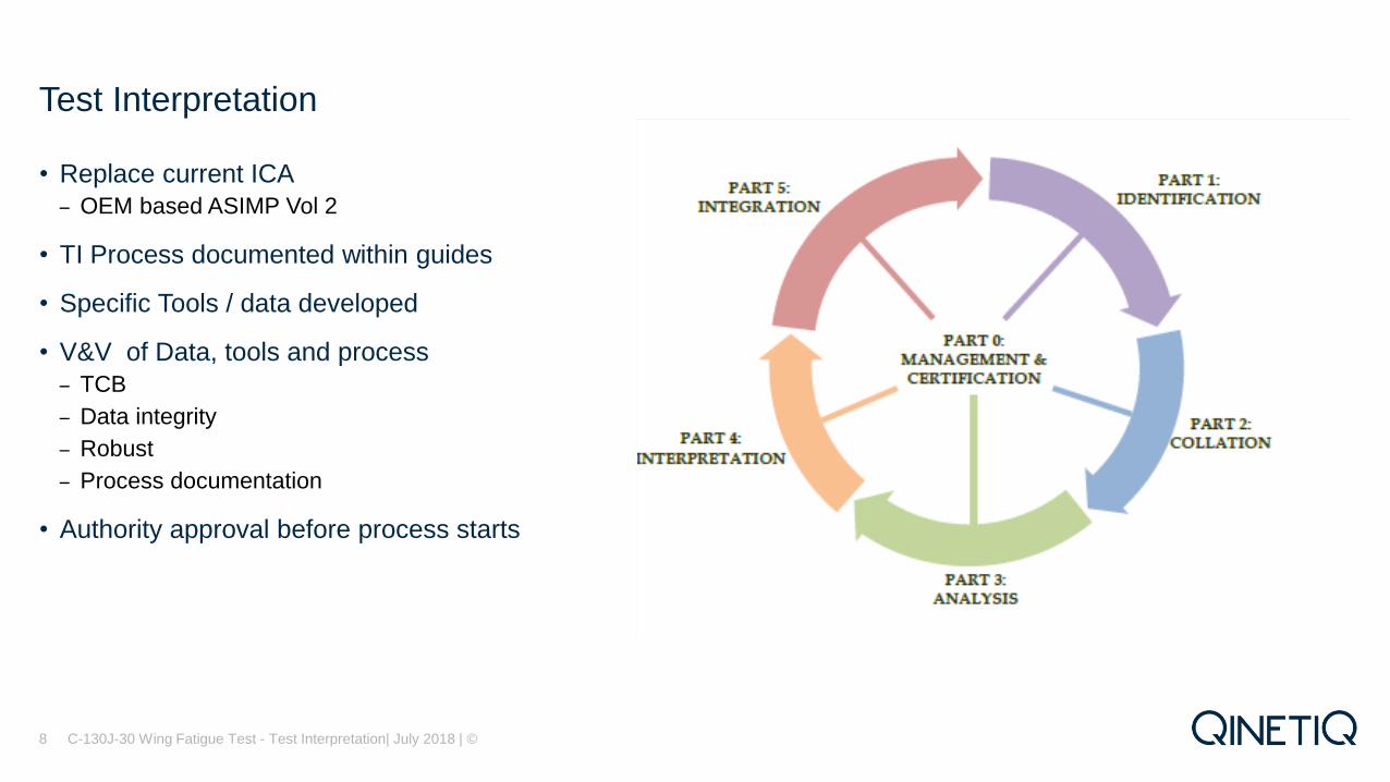
• Replace current ICA
– OEM based ASIMP Vol 2
• TI Process documented within guides
• Specific Tools / data developed
• V&V of Data, tools and process
– TCB
– Data integrity
– Robust
– Process documentation
• Authority approval before process starts
C-130J-30 Wing Fatigue Test - Test Interpretation| July 2018 | ©
Test Interpretation
8

• DADTA template
– FASTRAN
– Retardation crack growth model
– FAMS
– Strain life model
– Generates crack growth curve
– Calculates Intervals
– Includes
– Spectra
– Material data
– Accounts for multiple phase crack growth
– Continuing damage
C-130J-30 Wing Fatigue Test - Test Interpretation| July 2018 | ©
TI Tools/ Data
9
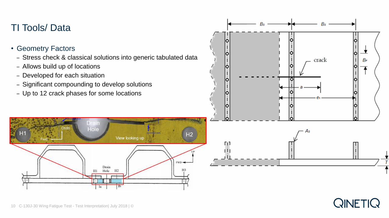
• Geometry Factors
– Stress check & classical solutions into generic tabulated data
– Allows build up of locations
– Developed for each situation
– Significant compounding to develop solutions
– Up to 12 crack phases for some locations
C-130J-30 Wing Fatigue Test - Test Interpretation| July 2018 | ©
TI Tools/ Data
10

• Geometry Factors
– For calibration
– Beta at fractographic recorded point
– Same point on the crack face
– Not at 5 and 80 degrees
– Crack aspect ratio
– Test crack progression
– Crack interaction
– For DTA
– Fixed aspect ratio a/c = 1.00
– Nominal blueprint geometry
– DTA crack progression
– Consistent with calibration Beta
C-130J-30 Wing Fatigue Test - Test Interpretation| July 2018 | ©
TI Tools/ Data
11

• Coupon testing
– Da/DN data
– short and long crack lengths
– Fatigue test spectrum clipping
• OEM Fracture toughness
• Handbook yield strength
C-130J-30 Wing Fatigue Test - Test Interpretation| July 2018 | ©
TI Tools/Data
12
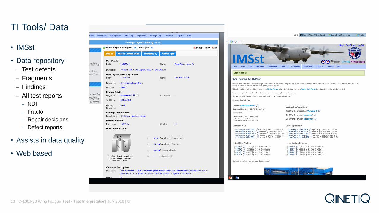
• IMSst
• Data repository
– Test defects
– Fragments
– Findings
– All test reports
– NDI
– Fracto
– Repair decisions
– Defect reports
• Assists in data quality
• Web based
C-130J-30 Wing Fatigue Test - Test Interpretation| July 2018 | ©
TI Tools/ Data
13
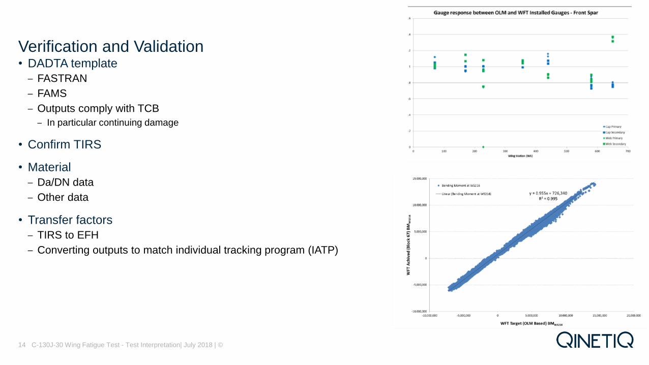
• DADTA template
– FASTRAN
– FAMS
– Outputs comply with TCB
– In particular continuing damage
• Confirm TIRS
• Material
– Da/DN data
– Other data
• Transfer factors
– TIRS to EFH
– Converting outputs to match individual tracking program (IATP)
C-130J-30 Wing Fatigue Test - Test Interpretation| July 2018 | ©14
Verification and Validation
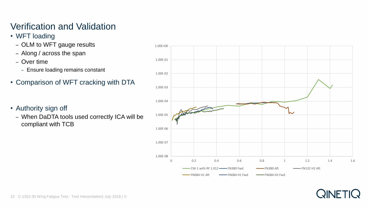
• WFT loading
– OLM to WFT gauge results
– Along / across the span
– Over time
– Ensure loading remains constant
• Comparison of WFT cracking with DTA
• Authority sign off
– When DaDTA tools used correctly ICA will be
compliant with TCB
C-130J-30 Wing Fatigue Test - Test Interpretation| July 2018 | ©
Verification and Validation
15
1.00E-08
1.00E-07
1.00E-06
1.00E-05
1.00E-04
1.00E-03
1.00E-02
1.00E-01
1.00E+00
0 0.2 0.4 0.6 0.8 1 1.2 1.4 1.6
CW-1 with RF 1.012 FN380 Fwd FN380 Aft FN132 H2 Aft
FN084 H1 Aft FN084 H1 Fwd FN084 H2 Fwd

• 1400 findings
– Most findings will not undergo fractography and DTA
• Extant SSI from LM Aero
• Critical test cracking
– Size and density of findings
– Criticality of failure
• Priority
– Test crack size
– Time of cracking
– Extant maintenance program impacts
C-130J-30 Wing Fatigue Test - Test Interpretation| July 2018 | ©
Selection of Locations
16
516
526
536
546
556
566
576
586
596
606
0 25 50 75 100 125 150 175 200 225
Fu
se
lage
Sta
tio
nWing Station
CWLS Panels

• Seven AP spectra
– ATS & TIRS
• Stress Transfer Factor (STF)
– Strain gauge
– OEM data
– FEM
• Test Representivity Factor (RF)
• Applied Test Spectrum
– ATS = AP ATS x STF x RF
– For fatigue test cracking
• Calibration Factor (CF)
• Test Interpretation Spectrum
– TIRS = AP TIRS x STF x CF
C-130J-30 Wing Fatigue Test - Test Interpretation| July 2018 | ©
Spectrum
17

• Factor on overall stress
– CF x ATS
• DTA of cracking
• Compare with qualitative
Fractography results
• Overcomes deficiencies
– STF
– Beta
C-130J-30 Wing Fatigue Test - Test Interpretation| July 2018 | ©
Calibration Factor
18

• Iterative process
• Simple beta
– Refined if required
– Account for other geometry
– Account for crack interaction
– Load redistribution
• Similar CF for adjacent cracks
• May have multiple CFs if local failure allowed
– Accounts for local stress transfer
C-130J-30 Wing Fatigue Test - Test Interpretation| July 2018 | ©
Calibration Factor
19

• Cracking Scenario
– Worst of test cracking
– LM DTA
– Or other?
• Multiple test cracks not necessarily the worst
case
– TCB requires only a single 0.05” flaw
– TCB continuation damage flaw
• Multi phase crack growth
• Intervals derived from crack growth curve as
per TCB
C-130J-30 Wing Fatigue Test - Test Interpretation| July 2018 | ©
DTA
20
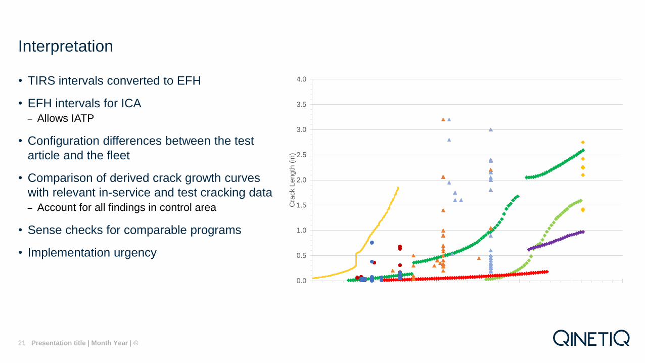
• TIRS intervals converted to EFH
• EFH intervals for ICA
– Allows IATP
• Configuration differences between the test
article and the fleet
• Comparison of derived crack growth curves
with relevant in-service and test cracking data
– Account for all findings in control area
• Sense checks for comparable programs
• Implementation urgency
Presentation title | Month Year | ©
Interpretation
21
0.0
0.5
1.0
1.5
2.0
2.5
3.0
3.5
4.0
0 20000 40000 60000 80000 100000 120000C
rack L
en
gth
(in
)
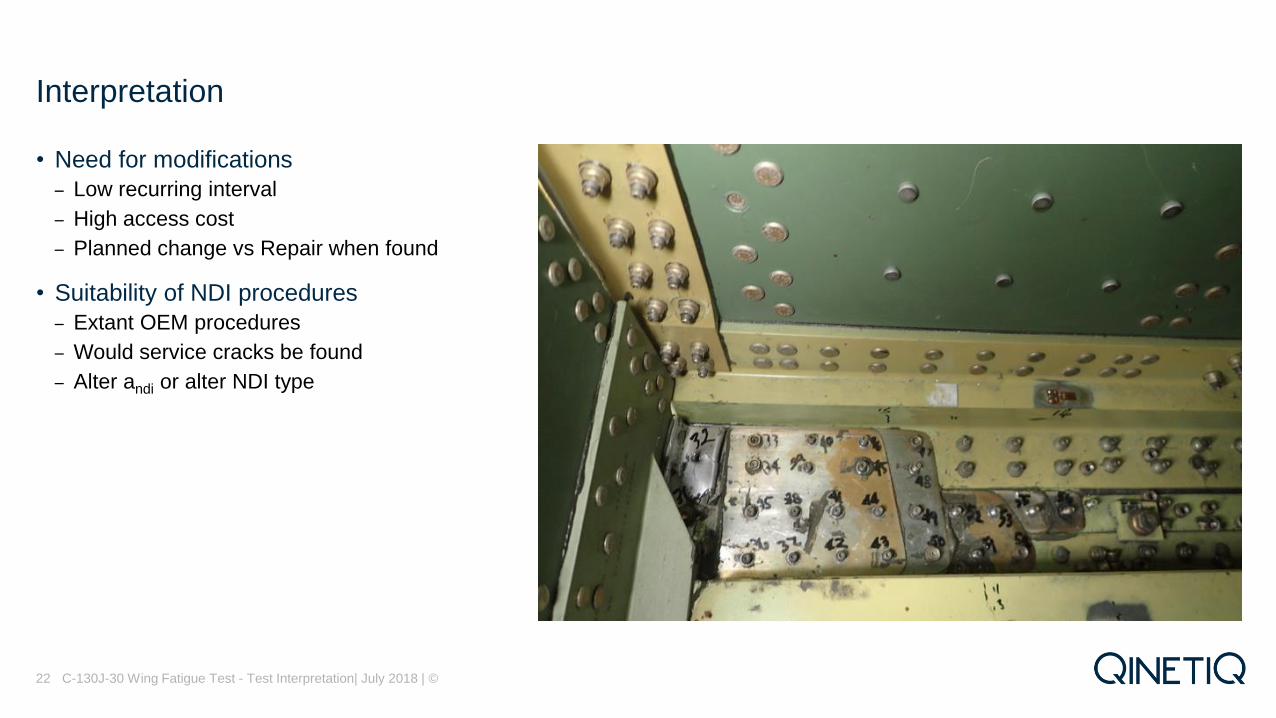
• Need for modifications
– Low recurring interval
– High access cost
– Planned change vs Repair when found
• Suitability of NDI procedures
– Extant OEM procedures
– Would service cracks be found
– Alter andi or alter NDI type
C-130J-30 Wing Fatigue Test - Test Interpretation| July 2018 | ©
Interpretation
22

• EFH intervals tracked by IATP
• ASIMP Vol 2 updates
• Ensure adequate time for implementation
– Escalate if any immediate safety issue present
– Reduced Threshold Interval
– Reduced Recurring Interval
• Provide aircraft specific ICA if needed
• Aim to align with major routine servicing's
• All may need refinement of analysis (not
100% on what this is)
• Suggestions for CAMO
C-130J-30 Wing Fatigue Test - Test Interpretation| July 2018 | ©
Implementation
23
0
2000
4000
6000
8000
10000
12000
14000
16000
18000
20000
2013 2016 2019 2021 2024
EFH
Date
New Threshold

• By end of TI
– 1400+ findings
– 55+ Fractography reports will be required
– 46 CF curves
– 57 DTAs
– 91 Locations
– locations covered DTA at more critical points
– 11 areas were MSD
– Just started to well advanced
– 6 locations with developed MED
– 4 locations for PRA
• Currently Completed
– 22 locations
– 13 DTAs
– 19 CF curves
C-130J-30 Wing Fatigue Test - Test Interpretation| July 2018 | ©
Summary
24
acrit = 1.859 in
aNDI = 0.30 in (US, SEC)
HNDI TIRS Hrs (US, SEC)
Safe
tyL
imit
FH
s

• Increase in thresholds and recurring
intervals
– Can be aligned with routine servicing's
– Increased aircraft availability
– Less chance of inspection damage
• Improvements believed to be due to
more advanced tools
C-130J-30 Wing Fatigue Test - Test Interpretation| July 2018 | ©25
Summary

• Fracto excellent
– used to account for load changes due to crack interaction
– Provides confidence
• Usefulness of strain gauge locations
– Not ideal for STF (local strain effects)
– Great for OLM comparisons
– Identify if load redistributes during course of testing
• Confidence in TI Process is dependent on V&V at multiple stages of
development
• Full understanding of Test outcome gives confidence in ICA outcome
• Next stage LOT
– Probabilistic Risk Assessments
C-130J-30 Wing Fatigue Test - Test Interpretation| July 2018 | ©
Lessons Learned
26

C-130J-30 Wing Fatigue Test - Test Interpretation| July 2018 | ©27