c 2013 hao jan liu - ideals
TRANSCRIPT

c© 2013 Hao Jan Liu

SMART-GRID-ENABLED DISTRIBUTED REACTIVE POWERSUPPORT WITH CONSERVATION OF VOLTAGE REDUCTION
BY
HAO JAN LIU
THESIS
Submitted in partial ful�llment of the requirementsfor the degree of Master of Science in Electrical and Computer Engineering
in the Graduate College of theUniversity of Illinois at Urbana-Champaign, 2013
Urbana, Illinois
Adviser:
Professor Thomas J. Overbye
ABSTRACT
As solar energy continues to increase in the current power grid, the reac-
tive power support capability from photovoltaic grid-tie inverters may be
used to regulate feeder voltage and reduce system losses on medium- and
low-voltage distribution systems. The focus of this thesis is to develop a
smart-grid-enabled control algorithm that will determine the amount of re-
active power injection or absorption required at each node to minimize the
deviation from the control voltage level. Once the voltage level is achieved,
implementing conservation of voltage reduction (CVR) further bene�ts the
system by increasing energy savings. Generally, reactive power support oc-
curs at the substation level, whereas with the communication advantages and
system feedback provided by smart-grid devices such as residential smart me-
ters, it facilitates an extensive reactive power support scheme that reaches
all the way to the end-users.
The method is tested on a modi�ed IEEE 13 node feeder system assuming
piecewise steady state operating conditions, full knowledge of the system
states, and two-way communication between the control center and the end-
users in the distribution systems. The control algorithms are modeled in
MATLAB and the simulations are performed in OpenDSS using the same
system to validate the results.
ii

To my parents and family, for their love and support
iii

ACKNOWLEDGMENTS
I would like to express my gratitude to my advisor, Professor Thomas Over-
bye. He is a true inspiration and I am lucky to have him as my advisor guiding
me through this invaluable experience at UIUC. I would like to thank the
entire "Team Overbye" for your support and encouragement. It has been a
great time working and studying with you all.
I would like to acknowledge the TCIPG (Trustworthy Cyber Infrastructure
for the Power Grid) for supporting this project and for the interactions and
collaborations it fosters. I would also like to thank the Illinois Department
of Commerce and Economic Opportunity for support provided under their
Illinois Center for a Smarter Electric Grid program.
I would like to thank my beloved friends around the world for their sup-
port during the di�cult times I experienced while in graduate school. Your
postcards and gifts from everywhere really made a di�erence.
Finally, I would like to thank my parents for their unconditional love and
support. It has been an exciting journey from being a professional ice skater
to a graduate student in electrical engineering, and yet they are always there
for me. For my family both in Taiwan and the USA, thank you for always
believing in me. I am incredibly fortunate to have an amazing life story
because of you.
iv

CONTENTS
LIST OF TABLES . . . . . . . . . . . . . . . . . . . . . . . . . . . . . vi
LIST OF FIGURES . . . . . . . . . . . . . . . . . . . . . . . . . . . . vii
Chapter 1 INTRODUCTION . . . . . . . . . . . . . . . . . . . . . . 1
Chapter 2 SIMULATION SOFTWARE AND METHOD . . . . . . . 42.1 Introduction . . . . . . . . . . . . . . . . . . . . . . . . . . . . 42.2 OpenDSS . . . . . . . . . . . . . . . . . . . . . . . . . . . . . 42.3 OpenDSS Architecture . . . . . . . . . . . . . . . . . . . . . . 52.4 Distribution System Exact Line Segment Model . . . . . . . . 72.5 Distribution Ladder Iterative Technique . . . . . . . . . . . . 112.6 Chapter Summary . . . . . . . . . . . . . . . . . . . . . . . . 12
Chapter 3 DISTRIBUTION SYSTEMS REACTIVE POWER SUP-PORT . . . . . . . . . . . . . . . . . . . . . . . . . . . . . . . . . . 133.1 Introduction . . . . . . . . . . . . . . . . . . . . . . . . . . . . 133.2 Power Losses Minimization Problem . . . . . . . . . . . . . . . 153.3 Voltage Problem in Distribution Feeder . . . . . . . . . . . . . 213.4 Chapter Summary . . . . . . . . . . . . . . . . . . . . . . . . 29
Chapter 4 DISTRIBUTED REACTIVE POWER SUPPORTWITHCONSERVATION OF VOLTAGE REDUCTION (CVR) ONZIP LOAD MODELING . . . . . . . . . . . . . . . . . . . . . . . . 324.1 Introduction . . . . . . . . . . . . . . . . . . . . . . . . . . . . 324.2 History of CVR . . . . . . . . . . . . . . . . . . . . . . . . . . 334.3 CVR Implementation . . . . . . . . . . . . . . . . . . . . . . . 344.4 ZIP Load Model . . . . . . . . . . . . . . . . . . . . . . . . . . 354.5 Distributed Reactive Power Support with CVR . . . . . . . . 384.6 Chapter Summary . . . . . . . . . . . . . . . . . . . . . . . . 45
Chapter 5 CONCLUSION . . . . . . . . . . . . . . . . . . . . . . . . 465.1 Future Work . . . . . . . . . . . . . . . . . . . . . . . . . . . . 46
REFERENCES . . . . . . . . . . . . . . . . . . . . . . . . . . . . . . . 48
v

LIST OF TABLES
3.1 Node Loading Values . . . . . . . . . . . . . . . . . . . . . . . 193.2 Voltage (p.u.) Before and After Reactive Power Compen-
sation with Percent Improvement at Last Solution . . . . . . 203.3 Node Voltage for Modi�ed IEEE 13 Node Feeder System . . . 303.4 Reactive Load for Modi�ed IEEE 13 Node Feeder System . . 30
4.1 Residential Appliance Load Type . . . . . . . . . . . . . . . . 354.2 ZIP Coe�cients for Di�erent Customer Class [31] . . . . . . . 354.3 CVR Methodologies Comparison . . . . . . . . . . . . . . . . 43
vi

LIST OF FIGURES
1.1 Smart-Grid Communication Network . . . . . . . . . . . . . . 2
2.1 OpenDSS Architecture . . . . . . . . . . . . . . . . . . . . . . 62.2 OpenDSS Solution Display . . . . . . . . . . . . . . . . . . . . 72.3 Three-phase Exact Line Segment Model . . . . . . . . . . . . 82.4 Three-nodes Distribution Feeder . . . . . . . . . . . . . . . . . 11
3.1 Solar Energy Industries Association (SEIA), GTMResearch[13] . . . . . . . . . . . . . . . . . . . . . . . . . . . . . . . . . 13
3.2 PV Inverter P/Q Capability Curve . . . . . . . . . . . . . . . 143.3 Two Terminals Line Segment . . . . . . . . . . . . . . . . . . . 163.4 Optimization Using Autoadd . . . . . . . . . . . . . . . . . . . 183.5 IEEE Modi�ed 13 Node Feeder . . . . . . . . . . . . . . . . . 193.6 Voltage Improvement Due to Loss Minimization . . . . . . . . 203.7 ANSI C84.1 [17] . . . . . . . . . . . . . . . . . . . . . . . . . . 223.8 A Line Segment in Distribution System . . . . . . . . . . . . . 243.9 SQP Solution Scheme . . . . . . . . . . . . . . . . . . . . . . . 273.10 Controllable Voltage Pro�le . . . . . . . . . . . . . . . . . . . 31
4.1 CVR with Adaptive Voltage Control [35] . . . . . . . . . . . . 364.2 ZIP Model . . . . . . . . . . . . . . . . . . . . . . . . . . . . . 374.3 ZIP Model for Di�erent Classes . . . . . . . . . . . . . . . . . 384.4 CVR: Real Power Consumption at Substation . . . . . . . . . 394.5 Voltage Pro�le after CVR . . . . . . . . . . . . . . . . . . . . 394.6 CVR: Power Factor and System Losses at Substation . . . . . 404.7 Voltage Pro�le after System Losses Minimization with CVR . 414.8 Real Power Consumption at Substation: Losses Minimiza-
tion with CVR . . . . . . . . . . . . . . . . . . . . . . . . . . 424.9 System Losses at Substation: Losses Minimization with CVR . 424.10 Voltage Pro�le after Distributed Voltage Support with CVR . 444.11 Real Power Consumption at Substation: Distributed Volt-
age Support with CVR . . . . . . . . . . . . . . . . . . . . . . 444.12 System Losses at Substation: Distributed Voltage Support
with CVR . . . . . . . . . . . . . . . . . . . . . . . . . . . . . 45
vii

Chapter 1
INTRODUCTION
A New York Times article about Northeast blackout of 2003 states: �Ex-
perts now think that on August 14, northern Ohio had a severe shortage of
reactive power, which ultimately caused the power plant and transmission
line failures that set the blackout in motion. Demand for reactive power
was unusually high because of a large volume of long-distance transmissions
streaming through Ohio to areas, including Canada, than needed to import
power to meet local demand. But the supply of reactive power was low be-
cause some plants were out of service and, possibly, because other plants were
not producing enough of it� [1]. The blackout resulted in the loss of 61800
MW electric load a�ecting over 50 million people with a mid-point cost of
$6.4 billion associated with loss or spoiled commodities [2]. According to
the U.S.-Canada Power System Outage Task Force [3], inadequate reactive
power support was the primary factor causing the voltage collapse, in which
voltages progressively decreased until the system could no longer stay stable.
This �nally led to the blackout. A corrective reactive power support control
scheme is proposed in [4]. After injecting reactive power at just �ve buses in
the system prior to the blackout, the voltages improve dramatically, and the
system is at a new stable equilibrium point.
Reactive power support is the backbone of grid voltage stability in trans-
mission systems and has been studied since the beginning of the power grid.
It is important not only in power system planning, but also guaranteeing
grid economy, reliability, and stability [5]. Traditionally, capacitor banks
and synchronous condensers are used to provide reactive power support in
the system, but many of them are being replaced by power electronics de-
vices such as �exible alternating current transmission systems (FACTS). The
acronym FACTS was added to the IEEE dictionary and the �rst static syn-
chronous compensator was installed in the system (STATCOM) in 1997 [6].
A STATCOM is based on a voltage source converter to provide reactive power
1

Figure 1.1: Smart-Grid Communication Network
support. The major bene�ts associated with STATCOM include more reac-
tive power support capacity in less space, maintenance-free technology, and
variable control of its reactive power support output [7]. The concepts of the
STATCOM are similar to many power electronics devices commonly used in
residential homes today. Such devices include plug-in hybrid electric vehicles
(PHEVs), uninterpretable power supplies (UPSs), solar photovoltaic (PV)
panels, lighting, computers, TVs, and others. Each device can contribute
a small amount of reactive power support when operating within its rating
limit; therefore, a localized reactive power support scheme may be feasible if
there is enough reactive power support capability in the system.
In recent years, distributed generators (DGs) have been integrated into
modern distribution systems [8]. Among these DGs, PVs are one of the fastest
growing renewable energy sources in the world as they are more commercially
viable to manufacture and install. Each PV panel requires an inverter which
has a signi�cant reactive power support capability compared with other resi-
dential power electronics devices. The motivation of this thesis lies in the use
of emerging smart grid devices such as residential smart meters with control
coordination among them to provide reactive power support from PV grid-tie
inverters as a means of regulating the distribution feeder voltage pro�le and
minimizing system losses. Generally, reactive power support occurs at the
substation level, whereas with the communication advantages and system
feedback provided by smart-grid devices as shown in Figure 1.1, it facilitates
2
an extensive reactive power support scheme that reaches all the way to the
end-user.
This thesis is organized as follows: Chapter 2 gives a brief introduction
to simulation software for modeling distribution systems and provides an
overview of distribution network power �ow modeling. Chapter 3 discusses
the uses of smart-grid-enabled distributed reactive power resources to achieve
some optimal control strategies, i.e., to minimize the feeder losses or maintain
a certain feeder voltage pro�le. Chapter 4 proposes the distributed reactive
power support with conservation of voltage reduction technique to maintain
the voltage limit, reduce energy consumption, and improve the feeder losses
pro�le. This thesis concludes in Chapter 5, which also presents possibilities
for future work.
3

Chapter 2
SIMULATION SOFTWARE AND METHOD
2.1 Introduction
This chapter gives a brief introduction to Open Distribution System Sim-
ulator (OpenDSS) for modeling distribution equipment and feeder systems.
Conventional Newton-Raphson and Gauss-Seidal methods are designed to
solve power �ow analysis in transmission networks. However, these methods
are inadequate for distribution networks because of the poor convergence
characteristics. The following features of the distribution networks cause the
issue of ill-conditioned matrices for these conventional load �ow methods [9]:
• Radial or weakly meshed systems
• Higher X/R ratio
• Untransposed conductors
• Unbalanced loading conditions
• Distributed generations
In order to solve the distribution power �ow, the OpenDSS is used and some
user de�ned control actions are modeled in MATLAB via COM interfacing.
2.2 OpenDSS
OpenDSS is an open source software developed by the Electric Power Re-
search Institute (EPRI). It is a comprehensive simulation tool for electric
utility distribution systems. It has both an in-process COM server DLL to
be interfaced with various third-party software platforms, such as MATLAB,
4

Python, VBA, C#, etc., and a stand-alone executable program to help users
in developing scripts and viewing results. The program supports not only
nearly all rms steady-state analysis commonly studied for utility distribution
planning and analysis, but also many new types of analysis designed for the
future needs, many of which are designed for the deregulation of utilities
and the ideas of emerging smart-grid. Some of the useful functions are the
following [10]:
• Distribution planning and analysis
• General multiphase AC circuit analysis
• Analysis of distributed generation interconnections
• Solar PV system simulation
• Wind plant simulation
• Distribution automation control assessment
• Protection system simulation
• Storage modeling
• Distribution state estimation
• Geomagnetically induced currents (GIC)
• EV impacts simulation
• Harmonic distortion analysis
2.3 OpenDSS Architecture
The Distribution System Simulator (DSS) executive controls the distribu-
tion system simulation, and the various distribution elements are classi�ed
into �ve object classes: power delivery elements, power conversion elements,
controls, meters, and general components of the main simulation engine.
The architecture of the OpenDSS is shown in Figure 2.1. The most com-
monly used power delivery elements are lines and transformers which are
multiphased and transport energy from one point in the system to another.
5

Figure 2.1: OpenDSS Architecture
Power conversion elements transform electrical energy from one form to an-
other and usually have a single connection to the distribution system. They
are modeled by representing their impedance or a complicated set of di�er-
ential equations to model their current injections. The most commonly used
power conversion elements are loads and generators.
Each element in the circuit is represented by the primitive Z and Y ma-
trices and is structured and managed in DSS executive by Delphi. The DSS
executive also controls the results collected from meter elements and im-
plementation of the control elements. The initial guess for the voltage is
obtained by solving a no load power �ow case where all the shunt elements
are disconnected. This ensures proper relationships between all phase angles
and voltage magnitudes. The iteration starts by converting all the power
conversion elements into current injection vectors and the sparse set of ma-
trices is solved until the voltages converge to a certain user-de�ned threshold.
The solution is found to converge well for most of the distribution networks
where it has a su�cient capacity to serve the load. If a control action is
needed, control iterations are performed after converging to a solution.
6

Figure 2.2: OpenDSS Solution Display
There are two types of method to solve the distribution power �ow in
OpenDSS, namely the iterative and direct power �ow solutions. Most distri-
bution systems can be solved easily by the iterative mode. This mode uses
a simple �xed-point iterative method and converges well in most cases. The
direct mode includes admittances of the generators and loads into the system
admittance matrix, which is solved directly without iterating. Usually, an
iterative mode is used for power �ow solution while a direct mode is used for
fault studies with linear load models [11].
Several di�erent reports such as power �ow, losses, and voltages can be
generated after obtaining the solution. A sample solution display is shown in
Figure 2.2. In this thesis, the �xed-point iterative method is adapted to solve
the power �ow. Therefore, the following section will give a brief introduction
to the methodology of this technique.
2.4 Distribution System Exact Line Segment Model
It is critical to understand the models and equations to represent overhead
and underground line segments in distribution systems since most of the lines
are untransposed and the loadings are unbalanced. The following equation
derivations are formulated and presented in [12]. Figure 2.3 represents the
total impedances and admittances for a three-phase line segment. Applying
7

Figure 2.3: Three-phase Exact Line Segment Model
Kirchho�'s current law (KCL) at node m, the following equation will be
obtained: IlineaIlineb
Ilinec
=
IaIbIc
m
+1
2·
Yaa Yab Yac
Yba Ybb Ybc
Yca Ycb Ycc
·VagVbg
Vcg
m
(2.1)
Equation 2.1 can be expressed in a simpli�ed form:
[Ilineabc] = [Iabc]m +1
2· [Yabc] · [V LGabc]m (2.2)
Applying Kirchho�'s voltage law (KVL) to the model:V agV bg
V cg
n
=
V agV bg
V cg
m
+
Zaa Zab Zac
Zba Zbb Zbc
Zca Zcb Zcc
·IlineaIlineb
Ilinec
(2.3)
In condensed form Equation 2.3 becomes:
[V LGabc]n = [V LGabc]m + [Zabc] · [Ilineabc] (2.4)
Substituting Equation 2.2 into Equation 2.4:
[V LGabc]n = [V LGabc]m + [Zabc] ·{
[Iabc]m +1
2· [Yabc] · [V LGabc]m
}(2.5)
8

Collecting the terms in Equation 2.5:
[V LGabc]n =
{[u] +
1
2· [Zabc] · [Yabc]
}· [V LGabc]m + [Zabc] · [Iabc]m (2.6)
where
[u] =
1 0 0
0 1 0
0 0 1
(2.7)
Equation 2.6 can be rewritten in the general form:
[V LGabc]n = [a] · [V LGabc]m + [b] · [Iabc]m (2.8)
where
[a] = [u] +1
2[Zabc] · [Yabc] (2.9)
[b] = [Zabc] (2.10)
Applying the KCL at node n:
[Iabc]n = [Ilineabc] +1
2· [Yabc] · [V LGabc]n (2.11)
Substituting Equation 2.2 into Equation 2.11:
[Iabc]n = [Iabc]m +1
2· [Yabc] · [V LGabc]m +
1
2· [Yabc] · [V LGabc]n (2.12)
Substituting Equation 2.6 into Equation 2.12:
[Iabc]n = [Iabc]m +1
2· [Yabc] · [V LGabc]m
+1
2· [Yabc]
({[u] +
1
2· [Zabc] · [Yabc]
}· [V LGabc]m + [Zabc] · [Iabc]m
)(2.13)
Collecting the terms in Equation 2.13:
9
[Iabc]n =
{[Yabc] +
1
4· [Yabc] · [Zabc] · [Yabc]
}· [V LGabc]m
+
{[u] +
1
2· [Yabc] · [Zabc]
}· [Iabc]m (2.14)
Equation 2.14 can be rewritten in the general form:
[Iabc]n = [c] · [V LGabc]m + [d] · [Iabc]m (2.15)
where
[c] = [Yabc] +1
4· [Yabc] · [Zabc] · [Yabc] (2.16)
[d] = [u] +1
2· [Zabc] · [Yabc] (2.17)
Combining Equation 2.8 and 2.15 into partitioned matrix form:[[V LGabc]n
[Iabc]n
]=
[[a] [b]
[c] [d]
]·
[[V LGabc]m
[Iabc]m
](2.18)
The determinant of matrix abcd is
[a] · [d]− [b] · [c] = [u] (2.19)
From Equation 2.19, Equation 2.18 can be rewritten as:[[V LGabc]m
[Iabc]m
]=
[[d] [−b]
[−c] [a]
]·
[[V LGabc]n
[Iabc]n
](2.20)
It is desired to get the voltage at node m as a function of voltages at node n
and the currents at node m; thus Equation 2.8 becomes:
[V LGabc]m = [a]−1 · ([V LGabc]n − [b] · [Iabc]m) (2.21)
10

Figure 2.4: Three-nodes Distribution Feeder
2.5 Distribution Ladder Iterative Technique
Since most distribution feeders are radial, the iterative Newton-Raphson and
Gauss-Seidal methods previously mentioned are not suitable for distribution
power �ow analysis. Instead, the ladder iterative technique is used. It has
two basics steps: the forward and the backward sweeps. The sweep process
is continued until the di�erence between the speci�ed and computed source
voltage converges within a tolerance band. Figure 2.4 is a simple three-node,
nonlinear ladder distribution feeder that will be used to explain the general
approach to solve the power �ow problem.
In this feeder, there are three nodes and two line segments. Each line
segment has a three-by-three impedance matrix ([ZeqL]) de�ned in Section
2.4. The impedance matrices are important because they will be used in the
voltage and current calculations during the sweep process.
The ladder iterative technique starts with a forward sweep from the source
to the end of the feeder to obtain the initial voltages at node 2 and 3 assuming
a no-load condition in the system. Then the backward sweep continues by
calculating the current from node 4. The load in this case is modeled as a
constant PQ source; therefore, the current can be obtained per phase using
Equation 2.22, where Sphase is the apparent power per-phase and VLN,phase is
the line to ground voltage per-phase.
Iabcphase =
(Sphase
VLN,phase
)∗
(2.22)
There are other options to model the load. OpenDSS has 8 di�erent pro-
gram de�ned load models:
• Normal: constant P and Q
• Constant impedance load
11
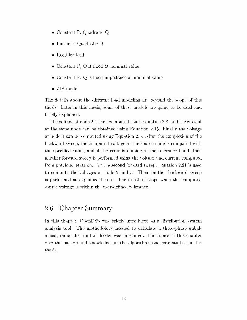
• Constant P, Quadratic Q
• Linear P, Quadratic Q
• Recti�er load
• Constant P; Q is �xed at nominal value
• Constant P; Q is �xed impedance at nominal value
• ZIP model
The details about the di�erent load modeling are beyond the scope of this
thesis. Later in this thesis, some of these models are going to be used and
brie�y explained.
The voltage at node 2 is then computed using Equation 2.8, and the current
at the same node can be obtained using Equation 2.15. Finally the voltage
at node 1 can be computed using Equation 2.8. After the completion of the
backward sweep, the computed voltage at the source node is compared with
the speci�ed value, and if the error is outside of the tolerance band, then
another forward sweep is performed using the voltage and current computed
from previous iteration. For the second forward sweep, Equation 2.21 is used
to compute the voltages at node 2 and 3. Then another backward sweep
is performed as explained before. The iteration stops when the computed
source voltage is within the user-de�ned tolerance.
2.6 Chapter Summary
In this chapter, OpenDSS was brie�y introduced as a distribution system
analysis tool. The methodology needed to calculate a three-phase unbal-
anced, radial distribution feeder was presented. The topics in this chapter
give the background knowledge for the algorithms and case studies in this
thesis.
12
Chapter 3
DISTRIBUTION SYSTEMS REACTIVEPOWER SUPPORT
3.1 Introduction
Solar photovoltaic (PV) power systems are one of the fastest growing re-
newable energy sources in the world. Industry statistics show that the total
capacity of grid-connected PV power systems has grown rapidly between 2005
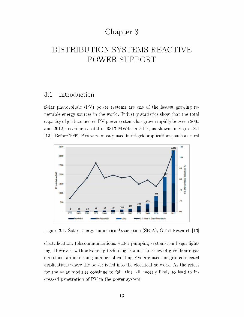
and 2012, reaching a total of 3313 MWdc in 2012, as shown in Figure 3.1
[13]. Before 1999, PVs were mostly used in o�-grid applications, such as rural
Figure 3.1: Solar Energy Industries Association (SEIA), GTM Research [13]
electri�cation, telecommunications, water pumping systems, and sign light-
ing. However, with advancing technologies and the issues of greenhouse gas
emissions, an increasing number of existing PVs are used for grid-connected
applications where the power is fed into the electrical network. As the prices
for the solar modules continue to fall, this will mostly likely to lead to in-
creased penetration of PV in the power system.
13

Figure 3.2: PV Inverter P/Q Capability Curve
The distribution systems di�er signi�cantly from the transmission systems,
which have a much lower X/R ratio. Therefore, the bus voltage sensitivity is
high for changes in both active and reactive power [14]. This thesis focuses
on the new emerging power devices that have the capability of changing
reactive power output. There are many existing reactive power resources in
the current distribution systems, such as inverters on solar panels, plug-in
hybrid electric vehicles (PHEVs), electric machines, and many other power
electronics devices. In the interest of this work, since most distributed PV
systems are in the distribution systems, the individual grid-tie inverter has
the capability to support reactive power locally when operating within the
power rating limit. A PV inverter operates in two quadrants (mode 1, 2, 3,
4, and 5) up to its power rating as shown in Figure 3.2. Mode 1 is the base
case where only the real power is produced with no reactive power injection
to the system. Mode 2 and 3 show power injection at a lagging and leading
power factor, respectively. Both the current magnitude and angle can be
adjusted with appropriate power electronics controls. Modes 1, 2, and 3 are
mostly likely to be in operation during the day when there is some real power
injection coming from the solar isolation, while modes 4 and 5 are solely
reactive power absorption and injection respectively and will be used during
the nighttime when there is no real power output from the PVs. Equation 3.1
determines the instantaneous capability of reactive power support in ith PV
14
inverter, where Qmaxinji is the maximum reactive power support, Srate
i is the
power rating of the inverter, and P inji is the real power output from the PV.
Since the inverter must be sized for peak sun conditions, it will practically
always have spare reactive power support capability during the daytime and
full reactive power support capability at night.
Qmaxinji =
√(Srate
i )2 − (P inji )2 (3.1)
In addition, the smart-grid technologies enable a system to coordinate the
reactive power resources over a secure communication infrastructure. Smart
meters for residential customers provide two-way communication between the
end-users and the control center. This opens the door to system feedback
which can be used to achieve some optimal control strategies, i.e., to mini-
mize the feeder losses or maintain the voltage at a certain node. Since each
load in the distribution system is served from di�erent feeders or circuits and
the system is usually radial, the analysis is di�erent from that of the trans-
mission system. This chapter will examine two di�erent smart-grid-enabled
reactive power support algorithms that assume piecewise steady state operat-
ing conditions, full knowledge of system states, and two-way communications
between the end-users and the control center in the distribution system.
3.2 Power Losses Minimization Problem
In the power system, the majority of the power losses are located in the
distribution network. Although the individual component loss is small, the
aggregate losses are approximately 4% of the total system load [15]. These
losses further increase the power demand during the peak load condition
and the fuel cost of a generator. Traditionally, capacitor placement and
conductor replacement have been the solutions for reducing power losses
in the distribution system. However, the former method is restricted by
its placement and sizing and the latter method sometimes can be costly to
implement. Figure 3.3 represents a line segment in the distribution system.
Real power loss (PLij) between nodes i and j can be given by the following
15
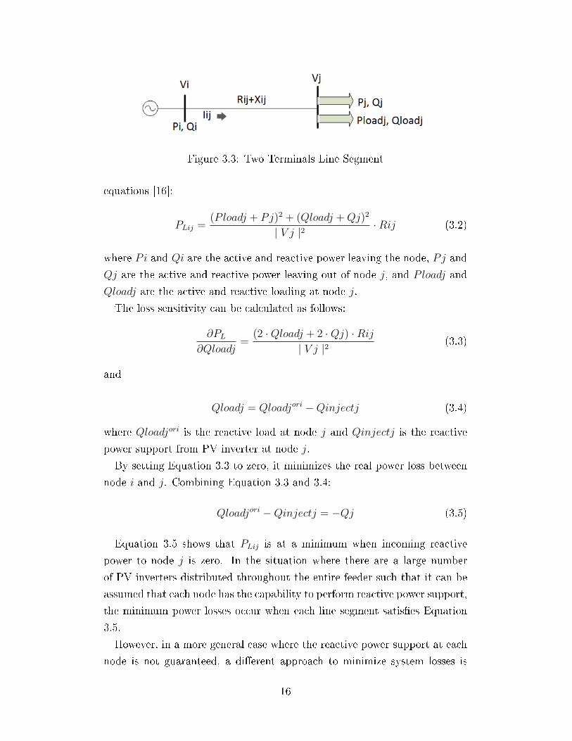
Figure 3.3: Two Terminals Line Segment
equations [16]:
PLij =(Ploadj + Pj)2 + (Qloadj +Qj)2
| V j |2·Rij (3.2)
where Pi and Qi are the active and reactive power leaving the node, Pj and
Qj are the active and reactive power leaving out of node j, and Ploadj and
Qloadj are the active and reactive loading at node j.
The loss sensitivity can be calculated as follows:
∂PL
∂Qloadj=
(2 ·Qloadj + 2 ·Qj) ·Rij| V j |2
(3.3)
and
Qloadj = Qloadjori −Qinjectj (3.4)
where Qloadjori is the reactive load at node j and Qinjectj is the reactive
power support from PV inverter at node j.
By setting Equation 3.3 to zero, it minimizes the real power loss between
node i and j. Combining Equation 3.3 and 3.4:
Qloadjori −Qinjectj = −Qj (3.5)
Equation 3.5 shows that PLij is at a minimum when incoming reactive
power to node j is zero. In the situation where there are a large number
of PV inverters distributed throughout the entire feeder such that it can be
assumed that each node has the capability to perform reactive power support,
the minimum power losses occur when each line segment satis�es Equation
3.5.
However, in a more general case where the reactive power support at each
node is not guaranteed, a di�erent approach to minimize system losses is
16
needed. In OpenDSS, the internal �Autoadd� mode places one capacitor, a
�xed amount of reactive power support per node, each solved at an optimal
location based on loss minimization [10]. Chapter 2 has shown that OpenDSS
uses the[I] = [Y ] · [V ] iterative technique to solve unknown voltages and
currents. �Autoadd� takes advantage of direct access to the compensation
current array [I] in the solution. To move a capacitor from node to node
only requires modifying the compensation current array. Since the [Y ] matrix
remains the same and does not need to be re-factorized, this accelerates the
convergence speed. Each solution usually takes about 2-4 iterations and it
outputs a percentage improvement per node to indicate the next best location
to supply reactive power. So, even with a larger network, the performance is
still very promising.
3.2.1 General Case Solved with OpenDSS �Autoadd� Mode
In a distribution system, if at least one node does not have reactive power
support capability, Equation 3.5 can no longer be satis�ed at each node. As
such, an exact optimal solution to minimize the losses does not exist, and
the optimization problem becomes:
minuf(x, u) = PL (3.6)
s.t. g(x, u) = 0
0.95 ≤ Vi ≤ 1.05
where g(x, u) = 0 is the distribution power �ow equation vector that will be
discussed in the following section.
Equation 3.6 determines the amount of reactive power injection needed
per node to minimize the system losses while keeping voltage within its tol-
erance band. There are many optimization techniques to solve the problem
described in Equation 3.6. OpenDSS uses �Autoadd� mode, which is a heuris-
tic search to �nd the optimal solutions. Figure 3.4 describes the iteration
technique for this optimization method and it is modeled in MATLAB to
obtain the solutions.
17

Figure 3.4: Optimization Using Autoadd
The algorithm was tested on a modi�ed IEEE 13 node distribution system
presented in Figure 3.5. The original IEEE 13 node model is a three-phase
unbalanced system and was modi�ed to a three-phase balanced network and
the loads were modeled as constant PQ devices.
In this case, the algorithm seeks the optimal reactive power injection level
from each node that has reactive power support capability. Table 3.1 shows
that the reactive power injection is directly proportional to the reactive load
at a certain node. This result agrees with Equation 3.5 where each node tries
to set its incoming reactive power to zero. Table 3.2 indicates that minimizing
losses also improves the voltage pro�le of the feeder and the percentages of
improvement at the last solution are all close to zero. Figure 3.6 is the voltage
pro�le at each node at a certain distance away from the substation before
and after the reactive power compensation, and it clearly depicts the voltage
improvement due to less reactive power �owing through the lines.
18

Figure 3.5: IEEE Modi�ed 13 Node Feeder
Table 3.1: Node Loading Values
Node # Load (kW) Load (kVar) Reactive Power Injection (kVar)
611 170 80 120634 160 110 180645 170 125 140646 230 132 140652 128 86 100670 1155 660 740671 17 10 0675 485 190 240692 170 151 80Total 2685 1544 1740
19

Table 3.2: Voltage (p.u.) Before and After Reactive Power Compensationwith Percent Improvement at Last Solution
Node # Initial Volts (p.u.) Final Volts (p.u.) % Improvement
611 0.9541 0.9839 -0.000590973634 0.9608 0.9861 -9.37E-05645 0.9683 0.9893 -0.000129876646 0.968 0.9891 -0.00016715652 0.9537 0.9838 -0.000621857670 0.9618 0.9868 -0.000166837671 0.9548 0.9841 -0.000777233675 0.9537 0.9837 -0.000564608692 0.9548 0.9841 -0.000471964
Power Losses: 2.16% Power Losses: 1.5%
Figure 3.6: Voltage Improvement Due to Loss Minimization
20

3.3 Voltage Problem in Distribution Feeder
The performance and service quality of distribution systems are based upon
uninterrupted power supply and satisfactory voltage level. Electric util-
ity companies usually cannot keep a constant voltage matching exactly the
nameplate voltage on the customer's utilization equipment. Therefore, the
American National Standards Institute (ANSI) set forth preferred voltage
levels and ranges within which utilities must stay [17]. In the US, the ANSI
standard is the basis for the state regulatory commission to set forth voltage
limits for di�erent classes of electric service.
The impacts of high penetration of PV have been studied in existing litera-
ture. These impacts can be classi�ed into two groups: impacts on distribution
and impacts on transmission. These impacts a�ect distribution system pro-
tection planning, voltage pro�ling, system stability, energy quality, network
planning, and economics [18]. Voltage irregularities are one of the major
power quality issues and 95% of the problems in electrical systems stem from
voltage problems [19]. Usually, a low steady-state voltage may lower lighting
levels, shrink TV pictures, and overheat motors; on the other hand, a high
steady-state voltage may reduce the life of electronic devices, increase energy
consumption of certain loads, and reduce light bulb life [20]. Therefore, it
is imperative to monitor and control the feeder voltage in order to minimize
potential voltage problems described above.
ANSI C84.1 has two voltage ranges based on a 120 V nominal system as
shown in Figure 3.7 [17].
• Range A: Service voltage range is plus or minus 5% of nominal (120
V).
• Range B: Utilization voltage range is plus 6% to minus 13% of nominal
(120 V).
Service voltage is the voltage measured at the ends of the service entrance
apparatus, and utilization voltage is the voltage measured at the end of an
apparatus.
In general, load power factor a�ects the voltage drop across a line segment.
For a high power factor load, the voltage drop mainly depends on the line
resistance, and for a low power factor load, the voltage drop would depend on
21

Figure 3.7: ANSI C84.1 [17]
the line reactance. Therefore, the low voltage pro�le usually happens when
there are many poor power factor loads in the system [21].
Several voltage control techniques keeping feeder voltages within permis-
sible limits have been developed for distribution systems. Some of these
controls are:
• Application of voltage-regulator in the distribution substations and pri-
mary feeders
• Application of capacitors in the distribution substations and primary
feeders
• Increasing of feeder conductor size
• Changing of feeder from single-phase to multiphase
• Increase of primary voltage level
• Rerouting of loads to new feeders
As the X/R ratio is lower in the distribution network, voltage is sensitive to
both active and reactive power. In this work, the reactive power support from
grid-tie inverters is considered as an alternative way to control the voltage
22
pro�le. With the communication advantages and system feedback provided
by smart-grid devices, the idea is to �nd an optimal reactive power support
level to improve power factors and low (high) voltage pro�le.
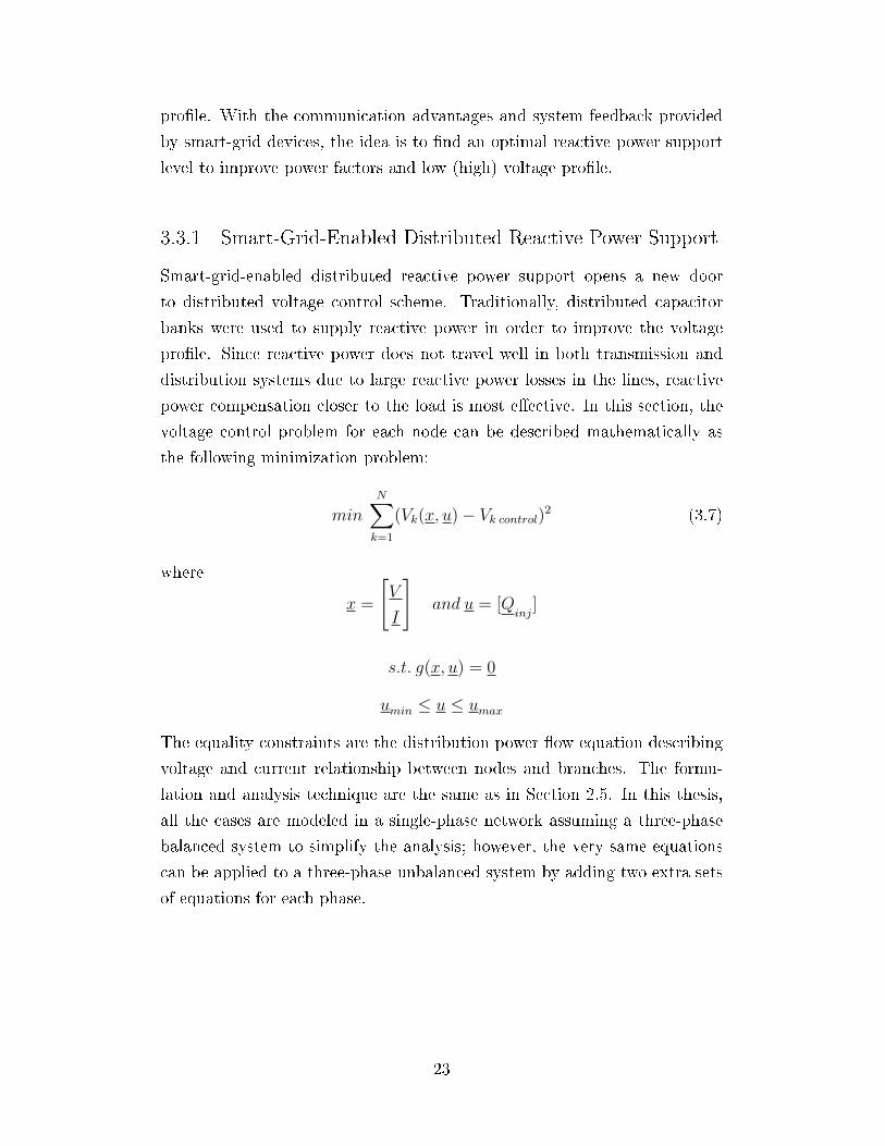
3.3.1 Smart-Grid-Enabled Distributed Reactive Power Support
Smart-grid-enabled distributed reactive power support opens a new door
to distributed voltage control scheme. Traditionally, distributed capacitor
banks were used to supply reactive power in order to improve the voltage
pro�le. Since reactive power does not travel well in both transmission and
distribution systems due to large reactive power losses in the lines, reactive
power compensation closer to the load is most e�ective. In this section, the
voltage control problem for each node can be described mathematically as
the following minimization problem:
min
N∑k=1
(Vk(x, u)− Vk control)2 (3.7)
where
x =
[V
I
]and u = [Q
inj]
s.t. g(x, u) = 0
umin ≤ u ≤ umax
The equality constraints are the distribution power �ow equation describing
voltage and current relationship between nodes and branches. The formu-
lation and analysis technique are the same as in Section 2.5. In this thesis,
all the cases are modeled in a single-phase network assuming a three-phase
balanced system to simplify the analysis; however, the very same equations
can be applied to a three-phase unbalanced system by adding two extra sets
of equations for each phase.
23

Figure 3.8: A Line Segment in Distribution System
Figure 3.8 represents a line segment in a distribution feeder with currents
and voltages of interest.
The equality constraint for each node is as follows:
Re [|V i | ]θV i − (Rij + j ∗Xij)· | Ii | ]θIi− | V j | ]θV j] = 0 (3.8)
Im [| V i | ]θV i − (Rij + j ∗Xij)· | Ii | ]θIi− | V j | ]θV j] = 0 (3.9)
Equation 3.8 and 3.9 can be expressed as:
| V i | ·cosθV i− | Ii | ·cosθIi ·Rij+ | Ii | ·sinθIi ·Xij− | V j | ·cosθV j = 0
(3.10)
| V i | ·sinθV i− | Ii | ·sinθIi ·Rij− | Ii | ·cosθIi ·Xij− | V j | ·sinθV j = 0
(3.11)
The equality constraints for the line currents are:
Re [| Ii | ]θIi =| Ij | ]θIj+ | IL | ]θIL] (3.12)
Im [| Ii | ]θIi =| Ij | ]θIj+ | IL | ]θIL] (3.13)
Equation 3.12 and 3.13 can be expressed as:
| Ii | ·cosθIi− | IL | ·cosθIL− | Ij | ·cosθIj = 0 (3.14)
24

| Ii | ·sinθ− | IL | ·sinθIL− | Ij | ·sinθIj = 0 (3.15)
where
IL = (SLoad
V j)∗ (3.16)
Substituting Equation 3.16 into Equation 3.14 and 3.15:
| IL | ·cosθIL =PLj· | V j | ·cosθV j + (QLj −Qinj,j)· | V j | ·sinθV j
| V j |2(3.17)
| IL | ·sinθIL =PLj· | V j | ·sinθV j − (QLj −Qinj,j)· | V j | ·cosθV j
| V j |2(3.18)
where Qinj,j is the control variable at node j for this voltage problem.
For this distributed voltage support problem, Equations 3.10, 3.11, 3.14,
and 3.15 are simply the equality constraints from the distribution power
�ow. The inequality constraints include the maximum reactive power support
capability at each node, the maximum line �ow capacity from each branch,
and maximum and minimum voltage allowed at each node. The proposed
optimization problem is then solved by a Lagrangian approach. The objective
function in Equation 3.7 is a quadratic function; therefore, the sequential
quadratic programing method is adopted to �nd the optimal solutions. The
detailed formulation for solving this optimization problem will be presented
in the next section.
3.3.2 Sequential Quadratic Programming (SQP)
SQP was �rst developed in 1984 to solve optimal power �ow (OPF) in trans-
mission systems. It has been tested with many larger-scale systems, and
generally the solutions converge to the optimal solution e�ciently for a well-
behaved problem [22]. The optimization problem in the previous section can
be formulated as follows [23]:
min f(x) (3.19)
25
s.t. g(x) = 0
h(x) ≤ 0
where x includes both the system states and control variables, f(x) is the
objective function, and g(x) and h(x) are the equality and inequality con-
straints, respectively.
Next, the constrained nonlinear optimization problem is converted to an
unconstrained nonlinear optimization using the Lagrangian function:
L(x, λ, µ) = f(x) + λT · g(x) + µT · h(x) (3.20)
where λ is the dual variable vector related to equality constraints and µ
is the penalty vector applied to inequality constraints when the inequality
constraints are violated.
Figure 3.9 shows the basic approach of SQP. The idea is to replace the
solutions of the nonlinear program (P) with a sequence of quadratic program
(QP) solutions. At the current point x(v) of the problem (P), the functions
g(x) and h(x) are linearized by �rst order truncated Taylor series expansions
as follows:
∆x = x− x(v) (3.21)
g(x) ∼= g(x(v)) + J(x(v)) ·∆x (3.22)
where the Jacobian is:
J(x(v)) ,∂g
∂x|x(v) (3.23)
Similarly, the inequality constraints can be expressed as:
h(x) ∼= h(x(v)) +H(x(v)) ·∆x ≤ 0 (3.24)
where
H(x(v)) ,∂h
∂x|x(v) (3.25)
26
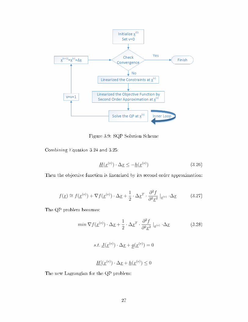
Figure 3.9: SQP Solution Scheme
Combining Equation 3.24 and 3.25:
H(x(v)) ·∆x ≤ −h(x(v)) (3.26)
Then the objective function is linearized by its second order approximation:
f(x) ∼= f(x(v)) +∇f(x(v)) ·∆x+1
2·∆xT · ∂
2f
∂2x2|x(v) ·∆x (3.27)
The QP problem becomes:
min∇f(x(v)) ·∆x+1
2·∆xT · ∂
2f
∂2x2|x(v) ·∆x (3.28)
s.t. J(x(v)) ·∆x+ g(x(v)) = 0
H[(x(v)) ·∆x+ h(x(v)) ≤ 0
The new Lagrangian for the QP problem:
27

L(∆x,∆λ,∆µ) = ∇f(x(v)) ·∆x+1
2·∆xT · ∂
2f
∂2x2|x(v) ·∆x
+ ∆λT · [J(x(v)) ·∆x+ g(x(v))] + ∆µT · [H[(x(v)) ·∆x+ h(x(v))] (3.29)
At the optimal solution, Karush�Kuhn�Tucker (KKT) conditions state:
∇L(∆x∗,∆λ∗,∆µ∗) = 0T (3.30)
Equation 3.30 can be solved using the Newton's scheme:∂2L∂2x2 JT HT
J 0 0
H 0 0
·∆x
∆λ
∆µ
= −
(∇xL)T
g
h
(3.31)
The scheme uses iterations of the form:
y(v+1) = y(v) + α(v) ·∆y(v) (3.32)
where α(v) is the current step size and
y(v) =
∆x(v)
∆λ(v)
∆µ(v)
(3.33)
with ∆y(v) obtained by:
∆y(v) = −
∂2L∂2x2 JT HT
J 0 0
H 0 0
−1
· [∇yL(y(v))]T (3.34)
3.3.3 IEEE 13 Node Feeder System Reactive Power VoltageControl Example
The proposed voltage problem can be formulated as a constrained nonlinear
optimization problem as follows:
min f(x, u) =‖ V − V control ‖2 (3.35)
28
s.t. g(x, u) = 0
h(x, u) ≤ 0
where x is the unknown system state vector obtained by solving distribution
power �ow equations, and u is the control vector; in this case, it is the
controllable reactive power injection from each available node. f(x, u) is the
objective function and g(x, u) and h(x, u) represent the equality constraints
from power equations and the inequality constraints from system physical
limitations, respectively.
The problem is converted from a constrained nonlinear form to uncon-
strained nonlinear form using the Lagrange function:
L(x, u, λ, µ) = f(x, u) + λT · g(x, u) + µT · h(x, u) (3.36)
This optimization can be solved by many di�erent methods. Using the SQP
technique explained in Section 3.3.2, the optimization problem was tested on
a modi�ed IEEE 13 node feeder system as shown in Figure 3.5. Again, it
is assumed that the system is a three-phase balanced network and the loads
were modeled as constant PQ devices. The smart-grid-enabled reactive power
support devices to be controlled are located at nodes 611, 634, 645, 646, 652,
670, 675, and 692. Tables 3.3 and 3.4 show that every controllable reactive
power resource participated in the action in order to increase the system
voltage close to 1 p.u. as shown in Figure 3.10. Although the voltage pro�le
is not perfectly �at at 1 p.u. due to reactive power support not being available
at every node, it is the best solution that can be achieved for this IEEE 13
node modi�ed case.
3.4 Chapter Summary
In the chapter, two di�erent optimization problems are presented and solved
with two di�erent techniques. Smart-grid-enabled distributed reactive power
support ultimately ensures a better power factor at the substation and im-
proves the feeder voltage pro�le. Widespread such devices would enable
29

Table 3.3: Node Voltage for Modi�ed IEEE 13 Node Feeder System
Node Initial Volts (p.u.) Final Volts (p.u.)
650 1 1633 0.969 0.9958634 0.9608 0.998670 0.9618 0.9958645 0.9683 0.9941646 0.968 0.9946692 0.9548 0.996675 0.9537 0.9959611 0.9541 0.9959652 0.9537 0.9959632 0.9695 0.9955680 0.9548 0.996684 0.9543 0.9959
Table 3.4: Reactive Load for Modi�ed IEEE 13 Node Feeder System
Node Initial Load (kVars) Final Load (kVars)
611 80 -28.3895634 110 -146.12645 125 741.651646 132 -374.667652 86 -45.547670 660 -509.887675 190 -134.641692 151 -181.962
30

Figure 3.10: Controllable Voltage Pro�le
system operators to gain control over voltages in distribution levels; further-
more, it would also reduce the reactive power demand from generators in the
transmission systems while increasing the real power production capability.
31
Chapter 4
DISTRIBUTED REACTIVE POWERSUPPORT WITH CONSERVATION OFVOLTAGE REDUCTION (CVR) ON ZIP
LOAD MODELING
4.1 Introduction
Traditionally, reactive power support in distribution systems is to minimize
the feeder losses and to provide local voltage support. The reactive power
injection is usually from switched capacitors and STATCOM throughout the
feeders [24],[25]. The focus of this thesis is on the studies of more active
control of distribution feeder voltages. One of the major issues most electric
utilities are facing today is conservation of energy in distribution systems.
The idea of conservation voltage reduction (CVR) may decrease the total
power consumption by reducing the voltage at the substation level [26]. This
method has been studied and performed by many utilities; however, the re-
sults are inconsistent with each other due to high dependencies of network
topologies and the nature of the load. CVR is best suited when most loads
are constant impedance loads since the energy consumption is directly pro-
portion to its voltage. On the other hand, some motor loads are less sensitive
to CVR. The small decrease in load power consumption may be very bene-
�cial to distribution utility companies if it is performed during peak loading
condition across a wide area in a competitive market environment. In this
chapter, three scenarios of distributed reactive power support were studied
to illustrate the e�ectiveness of the voltage control algorithm with CVR. In
the �rst study, the base case, a CVR is performed on an IEEE modi�ed
13 node feeder system to study the impacts on energy savings. Next, the
loss minimization is performed on the same system with CVR. Finally, every
node of the system is controlled at its minimum permissible voltage using
distributed voltage control algorithm.
A distribution system operates most e�ciently when it supplies its cus-
tomers with power at a voltage that lets the equipment perform most e�-
32

ciently and when the system power losses are minimized. While minimizing
system losses is more bene�cial to the utility's income, being able to increase
energy savings from its customers must be backed up by an economical anal-
ysis.
4.2 History of CVR
Many electric utilities have practiced CVR as an emergency measure to re-
duce loading during critical loading periods. During the severe shortage of
generating capacity in the 1960s, CVR was frequently used to balance power
supply and demand. The �rst wide-scale implementation of CVR was con-
ducted by the American Electric Power Service Corporation (AEP) in New
York during the Arab oil embargo in 1973. The report shows an average
3% drop in load for a 5%, 4 hours reduced voltage; however the investment
cost for installing CVR was not counted against saving at that time [27].
Since then, CVR has been adopted by many utility companies using di�er-
ent strategies; however, the results of these studies were not well documented
until the report by BC Hydro in 2010 [28]. BC Hydro is one of the pioneers
in North America in implementing voltage VAR optimization (VVO) in dis-
tribution systems. The �rst project was carried out with the main objective
of minimizing the distribution substation peak loading condition and allevi-
ating the transmission system capacity constraints. The report shows that
for a 1% voltage reduction, the energy saving per year is around 1.3 GWh
(~1%) while the peak winter demand was reduced by 1.6MW (1.1%). In
2005, Hydro-Quebec also launched a CVR pilot project and results shows
that for 1% voltage reduction, the reduction in energy is about 1.5 TWh
(0.4%) on its tested system [29]. The more recent study from EPRI shows
an annual energy reduction value ranging from 0.16% to about 1.2% in active
energy savings when CVR is implemented in a given test feeder system [30].
In [31], the authors show that a 4% reduction in voltage can be implemented
in most of New York City without any further investment cost of the current
network, and the energy savings are around 2.5 % for the whole year.
CV R Factor =∆Esaving
∆Vreduction(4.1)
33
CVR factor, as shown as in Equation 4.1, is the metric most often used
to determine the e�ectiveness of voltage reduction as a means of energy sav-
ing. From the previous studies, CVR factor is highly dependent on network
topologies and system loading conditions. Nevertheless, it can be concluded
that CVR in distribution systems is feasible and bene�cial.
4.3 CVR Implementation
In Section 3.3, the voltage at the end-user must be regulated to protect
electrical equipment. According to ANSI standards, the minimum service
voltage is 114V, which is 5% below the nominal voltage of 120V, and utiliza-
tion voltage should be at a minimum of 108V, which is 10% below nominal
voltage under contingency situation [32]. The implementation of CVR must
not violate this standard limit in order to prevent damage to appliances or
equipment.
There are two basic methods to implement CVR in a feeder system. The
�rst involves appropriate coordination with on-load tap-changers (OLTC)
transformer. The goal is to keep the most distant portion of the circuit above
the minimum voltage level using line-drop compensation (LDC) control. This
control will raise the voltage at a substation during heavy load conditions
and keep the boost in voltage at a minimum during light load. The control
does not need measurements from end of line voltages, but calculates its
compensation voltage level based on the model. The second method is voltage
spread reduction (VSR). VSR narrows voltage margin for a given feeder
system while maintaining the required minimum voltage at the most distant
load. For example, VSR can set voltage band to lower ±2.5% instead of the
standard ANSI value which has ±5% voltage band allowed on a feeder. These
two methods require coordination with substation transformers; however,
only local measurements are needed to implement CVR [33].
A newer strategy, Adaptive Voltage Control (AVC), has been developed
and implemented in many di�erent electric utilities since 2002 [34]. The con-
trol uses automatic control and remote measurements to adjust voltage level
at the substation. The main components are a Substation Data Collector &
Controller (SDCC), an Adaptive Voltage Controller (AVC), a Line Voltage
Monitor (LVM), and a voltage regulator as shown in Figure 4.1. The SDCC
34

Table 4.1: Residential Appliance Load Type
Constant Impedance Constant Current Constant Power
Incandescent Lamp Fluorescent Light ComputerWater Heater Control Current Load Air Conditioner
Table 4.2: ZIP Coe�cients for Di�erent Customer Class [31]
Class Zp Ip Pp Zq Iq Pq
Large Commercial 0.47 -0.53 1.06 5.30 -8.73 4.43Small Commercial 0.43 -0.06 0.63 4.06 -6.65 3.59
Residential 0.85 -1.12 1.27 10.96 -18.73 8.77Industrial 0 0 1 0 0 1
gathers data such as feeder power �ow, currents, and voltages at the substa-
tion while AVC sends in a control signal to OLTC based on communication
with the LVM. LVM can be located in the end of the line, critical loads, or
locations where a low voltage situation may occur [35]. Since this method
requires communication with remote monitors, it should be easily adapted
with smart-grid technology. In this chapter, this strategy is used to validate
the e�ectiveness of the proposed methods.
4.4 ZIP Load Model
There are three types of static load models: constant power, constant current
and constant impedance. For a constant power load, the power is indepen-
dent of voltage variation; for a constant current load, the power has linear
relationship with voltage; and for a constant impedance load, the power de-
pendence on voltage is quadratic. Table 4.1 shows di�erent load types in a
regular residential home. Since many loads have mixed load type characteris-
tics, a better load modeling technique is needed for simulation. One method
of modeling end-user load is with conventional ZIP load model as shown in
Figure 4.2. This model captures the load characteristic for each customer
class. The real and reactive power consumption is obtained from Equations
4.2 and 4.3. Equations 4.4 and 4.5 are normalizing constraints to ensure that
35

Figure 4.1: CVR with Adaptive Voltage Control [35]
36
Figure 4.2: ZIP Model
the load model consumes rated power when at rated voltage [36].
P = Po · [Zp · (V
V0)2 + Ip · (
V
V0) + Pp] (4.2)
Q = Qo · [Zq · (V
V0)2 + Iq · (
V
V0) + Pq] (4.3)
Zp + Ip + Pp = 1 (4.4)
Zq + Iq + Pq = 1 (4.5)
where:
P: real power consumption of the load
Q: reactive power consumption of the load
Po: real power consumption at rated voltage
Qo: reactive power consumption at rated voltage
V: actual terminal voltage
Table 4.2 gives the ZIP coe�cients associated each P-V and Q-V curve
quadratic approximation for each customer class for this study. Figure 4.3
shows power consumption under di�erent customer classes. It shows that
power consumption is more sensitive with voltage in residential level than in
large commercial level, and industrial load behaves like constant power load
regardless of voltage level.
37

Figure 4.3: ZIP Model for Di�erent Classes
4.5 Distributed Reactive Power Support with CVR
In this section, three di�erent CVR methodologies will be presented. Energy
reduction and system losses are both being studied to �nd the most e�cient
operation condition for the system. Equation 4.2 shows that the real power
consumption decreases with the voltage reduction. Therefore, the maximum
energy reduction occurs when each node is at its lowest allowable voltage
level. On the contrary, system losses may behave di�erently depending on
the network topology. System losses under CVR are critical because they
directly impact the e�ciency of the network. The losses comprise losses in
cables and transformer losses in cores and windings. The losses from cables
and transformer winding are proportional to the square of the current, while
transformer cores are proportional to the square of the voltage. When the
voltage reduces due to CVR, the former losses increase due to increase in
current. On the other hand, the latter losses decrease as a result of voltage
reduction. The behavior of these two types of losses is the opposite of that of
CVR. Results in [31] show that the size of network, load, and topology in�u-
ence the behavior of system losses. However, CVR in secondary distribution
network improves the overall system e�ciency.
38

Figure 4.4: CVR: Real Power Consumption at Substation
Figure 4.5: Voltage Pro�le after CVR
4.5.1 Base Case CVR
In this base case study, CVR is applied to a modi�ed IEEE 13 node feeder
system as shown in Figure 3.5. Each individual load is modeled as an ag-
gressive residential ZIP model. The ZIP coe�cient and load information are
obtained from Tables 4.2 and 3.1, respectively. Figure 4.4 shows that the
real power consumption decreases with reduction in voltage at the substa-
tion. In this case, the lowest permissible voltage at the substation is 0.9937
p.u. so there is no undervoltage violation in the feeder as shown in Figure
4.5. Furthermore, CVR improves substation PF from 0.85 to 0.87 (lagging)
but the system losses increase from 2.07% to 2.04% as shown in Figure 4.6.
39

Figure 4.6: CVR: Power Factor and System Losses at Substation
Overall, by applying CVR in this base case, the energy saving is ~ 60.5kW
with ~0.8kW increase in the system losses. Therefore, implementing CVR is
bene�cial in terms of energy saving.
4.5.2 System Losses Minimization with CVR
From Section 4.5.1, the results show that CVR has advantages in reduc-
ing power consumption; however, due to increase in current �ow throughout
the feeder, the line and transformer winding losses may predominate over
improvement in transformer core losses as in the case of the previous base
case study. To reduce the losses in the feeder, a system losses minimization
algorithm is performed as shown in Equation 4.6. The goal is to use dis-
tributed reactive power support as a means of control variables to solve the
minimization problem.
Min Ploss =n∑
j=1
| ij |2 ·Rj (4.6)
s.t. g(x, u) = 0
where n is total number of lines in the feeder, ij is the current �ow in line j,
and Rj is the resistance of line j.
The control algorithm steps are as follows:
1. Perform system losses minimization.
2. Reduce voltage at substation.
40

Figure 4.7: Voltage Pro�le after System Losses Minimization with CVR
3. Ensure that all the voltages are within limit; if yes, go back to Step 2.
4. Stop.
Controllable reactive power support at each node not only minimizes sys-
tem losses but also �attens the voltage pro�le along the feeder as shown in
Figure 4.7. As a result, the power consumption increases at the substation
compared with the base case in the same voltage setting. However, due to
a �atter voltage pro�le, the voltage regulator at the substation may set the
voltage tap lower than the base case without any voltage violation in the
system, as shown in Figure 4.8. In this case, the energy saving is about
2kW. However, Figure 4.9 shows a signi�cant improvement in system losses.
Therefore, implementing this control algorithm is more bene�cial in terms of
system losses reduction.
4.5.3 Distributed Voltage Support with CVR
From the previous two cases, implementing CVR improves energy saving in
the system. However, since system losses behave oppositely with reduction
in voltage, it is di�cult to �nd an operating point which maximizes energy
saving and minimizes the total system losses. The maximum energy saving
occurs when the system operates at its lowest permissible voltage level. But
41

Figure 4.8: Real Power Consumption at Substation: Losses Minimizationwith CVR
Figure 4.9: System Losses at Substation: Losses Minimization with CVR
42
Table 4.3: CVR Methodologies Comparison
Sub. Voltage Loading (kW) Losses (%)No CVR 1.037 2680.5 2.04
Base Case 0.9936 2620.4 2.07System Losses Minimization 0.9688 2618.3 1.58Distributed Voltage Support 0.9563 2613.7 1.75
the limitation of this technique is that the farthest node from the substation
usually su�ers from a much lower voltage and this constrains the voltage
regular at the substation to further reduce its voltage level. To overcome
this issue, a distributed voltage support framework with CVR is proposed.
Equation 4.7 is a constrained nonlinear optimization problem which can be
solved by the SQP method. The goal is to use distributed reactive power
resources at each node to �atten the voltage pro�le along the feeder to 1 p.u.
and then set the voltage at substation to 0.95 p.u. This method ensures that
every node is at its lowest permissible voltage level, which in turn maximizes
energy savings.
min f(x, u) =‖ V − V control ‖2 (4.7)
s.t. g(x, u) = 0
h(x, u) ≤ 0
In Equation 4.7, x is the unknown system state vector obtained by solving
distribution power �ow equations, and u is the control vector; in this case,
it is the controllable reactive power injection from each node. f(x, u) is the
objective function and g(x, u) and h(x, u) represent the equality constraints
from power equations and the inequality constraints from system physical
limitations, respectively, and V control is set to be 1 p.u. as shown in Figure
4.10.
Similarly to the previous case in Section 4.5.2, the power consumption in-
creases at the substation as a result of a �at 1 p.u. voltage pro�le as shown
in Figure 4.11. On the other hand, due to excess reverse reactive power in
the substation, the system losses increase compared with losses minimiza-
43
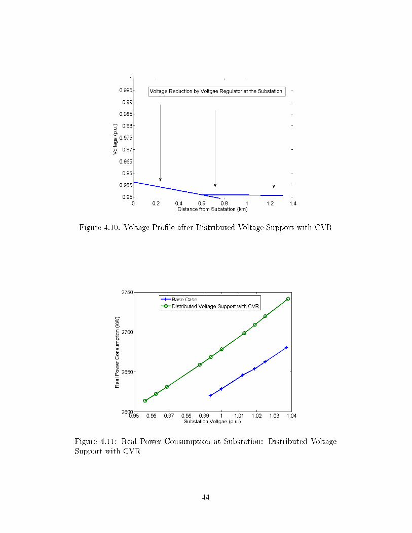
Figure 4.10: Voltage Pro�le after Distributed Voltage Support with CVR
Figure 4.11: Real Power Consumption at Substation: Distributed VoltageSupport with CVR
44

Figure 4.12: System Losses at Substation: Distributed Voltage Support withCVR
tion with the CVR method. Overall, distributed voltage support with CVR
maximizes the energy saving in the system and improves the system losses
pro�le when compared with implementing CVR alone as shown in Figure
4.12. Table 4.3 summarizes the overall e�ectiveness of the CVR method-
ologies. Compared with the case without CVR, the proposed distributed
voltage support with CVR method reduces power consumption by 66.8kW
in the current loading condition while reducing the system losses by 0.29%.
Results show that voltage reduction with distributed reactive power sup-
port in the given modi�ed IEEE 13 node feeder system is feasible and bene-
�cial. The proposed method not only solves low voltage violation locally but
also attains signi�cant savings in energy while reducing system losses.
4.6 Chapter Summary
In this chapter, three control algorithms with CVR are presented and solved
with AutoAdd function in OpenDSS and SQP method. Smart-grid-enabled
distributed reactive power support with CVR in distribution systems not only
reduces the real power losses but also improves the overall system-wide energy
savings. It shows great bene�ts to both utility companies and customers.
45
Chapter 5
CONCLUSION
This thesis proposes distributed reactive power support with a CVR algo-
rithm that uses two-way communication provided by smart-grid technology.
The solutions are obtained from SQP to minimize the deviation from the
control voltage level. The distributed voltage control scheme using reactive
power support from PV grid-tie inverters is tested in the modi�ed IEEE-
13 node feeder system. The results show that voltage reduction with dis-
tributed reactive power support in the given system is feasible and bene�cial.
The proposed method not only solves under/over-voltage issues locally but
also attains signi�cant savings in energy while reducing system feeder losses.
Smart-grid-enabled distributed reactive power support ultimately ensures a
better power factor at the substation and improves the feeder voltage pro�le.
Widespread such devices would enable system operators to gain control over
voltages in distribution levels; furthermore, it would also reduce the reactive
power demand from generators in the transmission systems while increasing
the real power production capability. Smart-grid-enabled distributed reactive
power support shows the possibility of increasing overall system e�ciency,
both in transmission and distribution systems, while improving the voltage
stability and system reliability.
5.1 Future Work
Although this control scheme can be remotely implemented in distribution
systems, communication integrity, system security, and consumer con�dence
remain as challenges to overcome. For future work, the current method
will be incorporated with a distributed control mode combining decentral-
ized and centralized schemes. The distributed control scheme will not only
determine the amount of reactive power required at each node to achieve
46

certain objective goals, but also reduce communication costs since the nu-
merous distributed resources do not have a direct communication link with
a higher level control. Moreover, the interactions between the cybersecurity
and power system will be examined to ensure a �smarter� future power grid.
47

REFERENCES
[1] R. Perez-Pena and E. Lipton, �Elusive force may lie at root of blackout,�The New York Times, September 2003.
[2] (2004, February) The economic impacts of the august 2003 blackout.Electric Consumers Resource Council (ELCON). [Online]. Available:http://www.elcon.org/EconomicImpactsOfAugust2003Blackout.pdf
[3] (2004, April) Final report on the august 14, 2003 blackout inthe united states and canada: Causes and recommendations.U.S.-Canada Power System Outage Task Force. [Online]. Available:http://reports.energy.gov/BlackoutFinalWeb.pdf
[4] K. Rogers, R. Klump, H. Khurana, and T. Overbye, �Smart-grid -enabled load and distributed generation as a reactive resource,� in In-novative Smart Grid Technologies (ISGT), 2010, 2010, pp. 1�8.
[5] X. Tian, X. Niu, H. Zang, H. Mu, and Z. Weichang, �Reactive powerplanning and strategy research considering backbone grid voltage sta-bility,� in Power Electronics and Motion Control Conference (IPEMC),2012 7th International, vol. 4, 2012, pp. 2789�2793.
[6] C. R. X-P. Zhang and B. Pal, Flexible AC Transmission Systems: Mod-elling and Control. Springer, March 2006.
[7] M. Noroozian, A. Petersson, B. Thorvaldson, B. Nilsson, and C. Tay-lor, �Bene�ts of SVC and STATCOM for electric utility application,� inTransmission and Distribution Conference and Exposition, 2003 IEEEPES, vol. 3, 2003, pp. 1192�1199.
[8] M. A. Kashem and G. Ledwich, �Multiple distributed generators fordistribution feeder voltage support,� Energy Conversion, IEEE Trans-actions on, vol. 20, no. 3, pp. 676�684, 2005.
[9] K. Balamurugan and D. Srinivasan, �Review of power �ow studies ondistribution network with distributed generation,� in Power Electronicsand Drive Systems (PEDS), 2011 IEEE Ninth International Conferenceon, 2011, pp. 411�417.
48
[10] OpenDSS Manual, Electric Power Research Institute, July 2010.
[11] V. Ramachandran, �Modeling of utility distribution feeder in opendssand steady state impact analysis of distributed generation,� Master'sthesis, West Virginia University, 2011.
[12] W. H. Kersting, Distribution System Modeling and Analysis. New York,NY: CRC Press, 2001.
[13] U.S. Solar Market Insight - 2012 Year in Review, Solar Energy Indus-tries Association (SEIA), GTM Research Std., 2012.
[14] A. Keane, L. Ochoa, E. Vittal, C. Dent, and G. Harrison, �Enhanced uti-lization of voltage control resources with distributed generation,� PowerSystems, IEEE Transactions on, vol. 26, no. 1, pp. 252�260, 2011.
[15] D. I. H. Sun, S. Abe, R. Shoults, M.-S. Chen, P. Eichenberger, andD. Farris, �Calculation of energy losses in a distribution system,� PowerApparatus and Systems, IEEE Transactions on, vol. PAS-99, no. 4, pp.1347�1356, 1980.
[16] T. Samimi Asl and S. Jamali, �Optimal capacitor placement size and lo-cation of shunt capacitor for reduction of losses on distribution feeders,�in Clean Electrical Power, 2009 International Conference on, 2009, pp.223�226.
[17] Voltage Ratings for Electric Power Systems and Equipment, AmericanNational Standards Institute Std. ANSI C84.1, 1977.
[18] J. S. N. Hadjsaid, Electrical Distribution Networks. John Wiley & Sons,Inc., 2011.
[19] J. Peas Lopes, �Integration of dispersed generation on distributionnetworks-impact studies,� in Power Engineering Society Winter Meet-ing, 2002. IEEE, vol. 1, 2002, pp. 323�328 vol.1.
[20] T. Gonen, Electric Power Distribution System Engineering. CRC, 2008.
[21] C. Brice, �Comparison of approximate and exact voltage drop calcula-tions for distribution lines,� Power Apparatus and Systems, IEEE Trans-actions on, vol. PAS-101, no. 11, pp. 4428�4431, 1982.
[22] R. Burchett, H. Happ, and D. R. Vierath, �Quadratically convergentoptimal power �ow,� Power Apparatus and Systems, IEEE Transactionson, vol. PAS-103, no. 11, pp. 3267�3275, 1984.
[23] G. Gross, �Sequential quadratic programing solution of the OPF,� classnotes for ECE 573, Department of Electrical and Computer Engineering,University of Illinois at Urbana Champaign, 2013.
49

[24] H. Xin, Z. Qu, J. Seuss, and A. Maknouninejad, �A self-organizing strat-egy for power �ow control of photovoltaic generators in a distributionnetwork,� Power Systems, IEEE Transactions on, vol. 26, no. 3, pp.1462�1473, 2011.
[25] D. Sattianadan, M. Sudhkaran, K. Vijayakumar, and S. Vidyasagar,�Optimal placement of capacitor in radial distribution system usingPSO,� in Sustainable Energy and Intelligent Systems (SEISCON 2011),International Conference on, 2011, pp. 326�331.
[26] G. Park and R. Colony, �Voltage reduction as a means of reducing dis-tribution load,� Power Apparatus and Systems, IEEE Transactions on,vol. 96, no. 2, pp. 628�634, 1977.
[27] R. F. Preiss and V. J. Warnock, �Impact of voltage reduction on energyand demand,� Power Apparatus and Systems, IEEE Transactions on,vol. PAS-97, no. 5, pp. 1665�1671, 1978.
[28] V. Dabic, C. Siew, J. Peralta, and D. Acebedo, �Bc hydro's experienceon voltage var optimization in distribution system,� in Transmission andDistribution Conference and Exposition, 2010 IEEE PES, 2010, pp. 1�7.
[29] S. Lefebvre, G. Gaba, A.-O. Ba, D. Asber, A. Ricard, C. Perreault, andD. Chartrand, �Measuring the e�ciency of voltage reduction at hydro-quebec distribution,� in Power and Energy Society General Meeting -Conversion and Delivery of Electrical Energy in the 21st Century, 2008IEEE, 2008, pp. 1�7.
[30] W. Sunderman, �Conservation voltage reduction system modeling, mea-surement, and veri�cation,� in Transmission and Distribution Confer-ence and Exposition (T D), 2012 IEEE PES, 2012, pp. 1�4.
[31] M. Diaz-Aguilo, J. Sandraz, R. Macwan, F. de Leon, D. Czarkowski,C. Comack, and D. Wang, �Field-validated load model for the analysis ofCVR in distribution secondary networks: Energy conservation,� PowerDelivery, IEEE Transactions on, vol. 28, no. 4, pp. 2428�2436, 2013.
[32] Voltage Tolerance Boundary, Paci�c Gas and Electric Company Std.,1999.
[33] J. G. De Steese, S. B. Merrick, and B. Kennedy, �Estimating methodol-ogy for a large regional application of conservation voltage reduction,�Power Systems, IEEE Transactions on, vol. 5, no. 3, pp. 862�870, 1990.
[34] T. Wilson, �Measurement and veri�cation of distribution voltage opti-mization results for the ieee power amp; energy society,� in Power andEnergy Society General Meeting, 2010 IEEE, 2010, pp. 1�9.
50

[35] T. L. Wilson, �Energy conservation with voltage reduction - fact or fan-tasy,� in Rural Electric Power Conference, 2002.
[36] K. Schneider, J. Fuller, and D. Chassin, �Evaluating conservation volt-age reduction: An application of gridlab-d: An open source softwarepackage,� in Power and Energy Society General Meeting, 2011 IEEE,2011, pp. 1�6.
51