c h 4 t he m edium a ccess c ontrol s ublayer 1 medium access control: a means of controlling access...
TRANSCRIPT
CH 4 THE MEDIUM ACCESS CONTROL SUBLAYER
1
Medium Access Control: a means of controlling access to the medium to promote orderly and efficient use.

OSI MODEL AND PROJECT 802
2

THE CHANNEL ALLOCATION PROBLEM
• Static Channel Allocation in LANs and MANsFDM: small and constant users, heavy load of traffic of each.TDM:same problem. Poor performance.None of the static channel allocation methods work well with bursty traffic.
• Dynamic Channel Allocation in LANs and MANs
3

PURE ALOHA
In pure ALOHA, frames are transmitted at completely arbitrary times.
4
Multiple Access Protocols

PURE ALOHA (2)
Vulnerable period for the shaded frame. 5
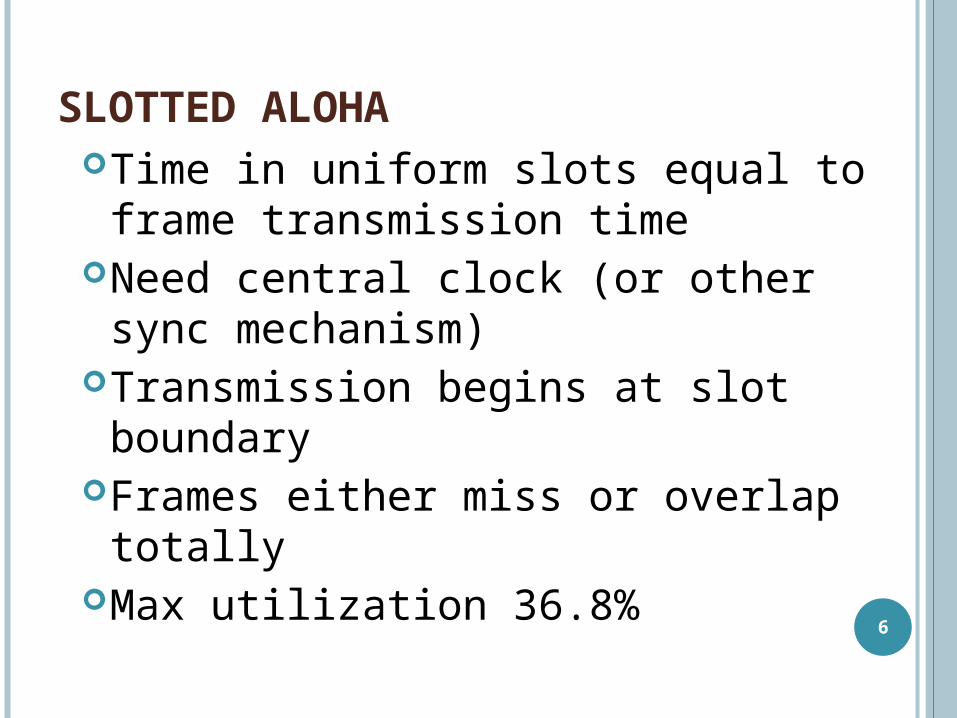
SLOTTED ALOHA Time in uniform slots equal to
frame transmission timeNeed central clock (or other sync
mechanism)Transmission begins at slot
boundaryFrames either miss or overlap
totallyMax utilization 36.8% 6

RELATIVE FORMULAS FOR THE ALOHA
7
Throughput orChannel Utilization
Probability of collision Probability of success
Pure ALOHASlotted ALOHA
tG GeGeS 22 tGr eecollisionP 22 11)(
tGr eeSuccessP 22)(
tG GeGeS tGr eecollisionP 11)( tG
r eeSuccessP )(
tG sec/: request slotrequestG /:
rate data
size frame
vilocity
distance fp ttt

PURE ALOHA AND SLOTTED ALOHA
Throughput versus offered traffic for ALOHA systems.8

PERSISTENT AND NONPERSISTENT CSMA
All stations know that a transmission has started almost immediately
First listen for clear medium (carrier sense)
If medium idle, transmit with a probability.
If two stations start at the same instant, collision
Propagation time is much less than transmission time
Wait reasonable time (round trip plus ACK contention)
No ACK then retransmit
9

PERSISTENT AND NONPERSISTENT CSMA
Comparison of the channel utilization versus load for various random access protocols.
10

CSMA/CD (WITH COLLISION DETECTION)
If collision detected, jam then cease transmission rather than finish transmitting their frame
After jam, wait random time then start again
Half-duplex systemSave time and bandwidth.Basis of Ethernet LAN.
11

CSMA/CDOPERATION
12

TOKEN RING (802.5)
MAC protocolSmall frame (token) circulates when idleStation waits for tokenChanges one bit in token to make it SOF for data
frameAppend rest of data frameFrame makes round trip and is absorbed by
transmitting stationStation then inserts new token when transmission
has finished and leading edge of returning frame arrives
Under light loads, some inefficiencyUnder heavy loads, round robin makes efficiency
and fair. 13
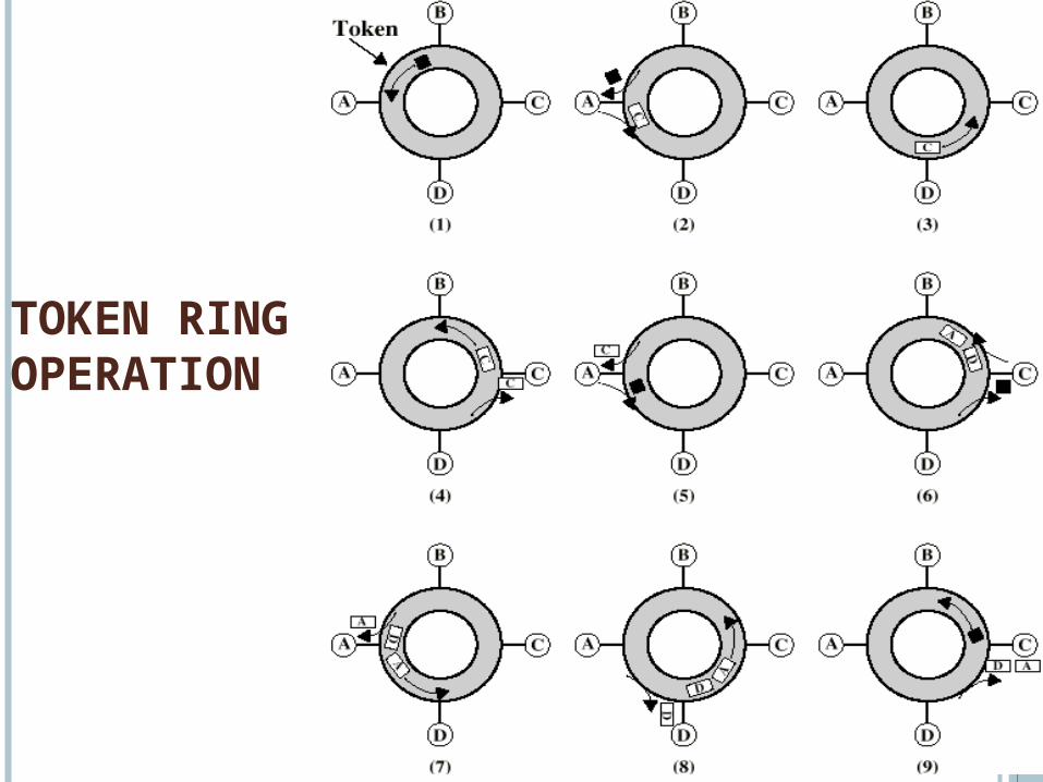
TOKEN RINGOPERATION
14

FDDI MAC PROTOCOL
Fiber Distributed Data InterfaceAs for 802.5 except:
Station seizes token by aborting token transmission
Once token captured, one or more data frames transmitted
New token released as soon as transmission finished
15

ETHERNET
• Ethernet Cabling• Manchester Encoding• The Ethernet MAC Sublayer Protocol• The Binary Exponential Backoff
Algorithm• Ethernet Performance• Switched Ethernet• Fast Ethernet• Gigabit Ethernet• IEEE 802.2: Logical Link Control
16

13.17
Ethernet evolution through four generations

13
.18
Figure 13.8 Categories of Standard Ethernet

ETHERNET CABLING
The most common kinds of Ethernet cabling. 19
13
.20
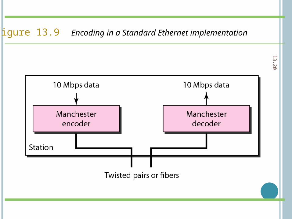
Figure 13.9 Encoding in a Standard Ethernet implementation

13
.21
Figure 13.10 10Base5 implementation

13
.22
Figure 13.11 10Base2 implementation

13
.23
Figure 13.12 10Base-T implementation

13
.24
Figure 13.13 10Base-F implementation

13
.25
Table 13.1 Summary of Standard Ethernet implementations

ETHERNET TOPOLOGY
Cable topologies. (a) Linear, (b) Spine, (c) Tree, (d) Segmented.
26

BASEBAND CONFIGURATION The size limitation is
usually solved by using repeaters to divide the medium into smaller segments
Repeaters relay digital signals in both directions, making the segments appear like one medium
As repeaters recover the digital signal, they remove any attenuation 27

13
.28
Figure 13.15 A network with and without a bridge

13
.29
Figure 13.16 Collision domains in an unbridged network and a bridged network

13
.30
Figure 13.17 Switched Ethernet

13
.31
Figure 13.18 Full-duplex switched Ethernet

13
.32
13-4 FAST ETHERNET13-4 FAST ETHERNET
Fast Ethernet was designed to compete with LAN Fast Ethernet was designed to compete with LAN protocols such as FDDI or Fiber Channel. IEEE protocols such as FDDI or Fiber Channel. IEEE created Fast Ethernet under the name 802.3u. Fast created Fast Ethernet under the name 802.3u. Fast Ethernet is backward-compatible with Standard Ethernet is backward-compatible with Standard Ethernet, but it can transmit data 10 times faster at a Ethernet, but it can transmit data 10 times faster at a rate of 100 Mbps. rate of 100 Mbps.
MAC SublayerPhysical Layer
Topics discussed in this section:Topics discussed in this section:

13
.33
Figure 13.19 Fast Ethernet topology

13
.34
Figure 13.20 Fast Ethernet implementations

13
.35
Figure 13.21 Encoding for Fast Ethernet implementation

13
.36Table 13.2 Summary of Fast Ethernet implementations

13
.37
13-5 GIGABIT ETHERNET13-5 GIGABIT ETHERNET
The need for an even higher data rate resulted in the The need for an even higher data rate resulted in the design of the Gigabit Ethernet protocol (1000 Mbps). design of the Gigabit Ethernet protocol (1000 Mbps). The IEEE committee calls the standard 802.3z.The IEEE committee calls the standard 802.3z.
MAC SublayerPhysical Layer
Ten-Gigabit Ethernet
Topics discussed in this section:Topics discussed in this section:

13
.38
In the full-duplex mode of Gigabit Ethernet, there is no collision;the maximum length of the cable is determined by the signal attenuation
in the cable.
Note

13
.39
Figure 13.22 Topologies of Gigabit Ethernet

13
.40
Figure 13.23 Gigabit Ethernet implementations

13
.41
Figure 13.24 Encoding in Gigabit Ethernet implementations

13
.42Table 13.3 Summary of Gigabit Ethernet implementations

13
.43
Table 13.4 Summary of Ten-Gigabit Ethernet implementations

SWITCHED ETHERNET
A simple example of switched Ethernet. 44

FAST ETHERNETFAST ETHERNET
Fast Ethernet was designed to compete with LAN Fast Ethernet was designed to compete with LAN protocols such as FDDI or Fiber Channel. IEEE protocols such as FDDI or Fiber Channel. IEEE created Fast Ethernet under the name 802.3u. Fast created Fast Ethernet under the name 802.3u. Fast Ethernet is backward-compatible with Standard Ethernet is backward-compatible with Standard Ethernet, but it can transmit data 10 times faster at a Ethernet, but it can transmit data 10 times faster at a rate of 100 Mbps. rate of 100 Mbps.
45

Fast Ethernet topology
46

Fast Ethernet implementations
47

13.48
GIGABIT ETHERNETGIGABIT ETHERNET
The need for an even higher data rate resulted in the The need for an even higher data rate resulted in the design of the Gigabit Ethernet protocol (1000 Mbps). design of the Gigabit Ethernet protocol (1000 Mbps). The IEEE committee calls the standard 802.3z.The IEEE committee calls the standard 802.3z.

GIGABIT ETHERNET
(a) A two-station Ethernet.(b) A multistation Ethernet.
49

GIGABIT ETHERNET (2)
50
Gigabit Ethernet - DifferencesCarrier extensionAt least 4096 bit-times long (512 for 10/100)Frame bursting extended to 200m.New coding

Summary of Ten-Gigabit Ethernet implementations
51

IEEE standard for LANs
52

IEEE 802.2: LOGICAL LINK CONTROL
(a) Position of LLC. (b) Protocol formats.
53

54
ETHERNET MAC SUBLAYER PROTOCOL
WCB/McGraw-Hill The McGraw-Hill Companies, Inc., 1998

55
PDU FORMAT
WCB/McGraw-Hill The McGraw-Hill Companies, Inc., 1998

MINIMUM AND MAXIMUM LENGTH
56

13.57
Example of an Ethernet address in hexadecimal notation
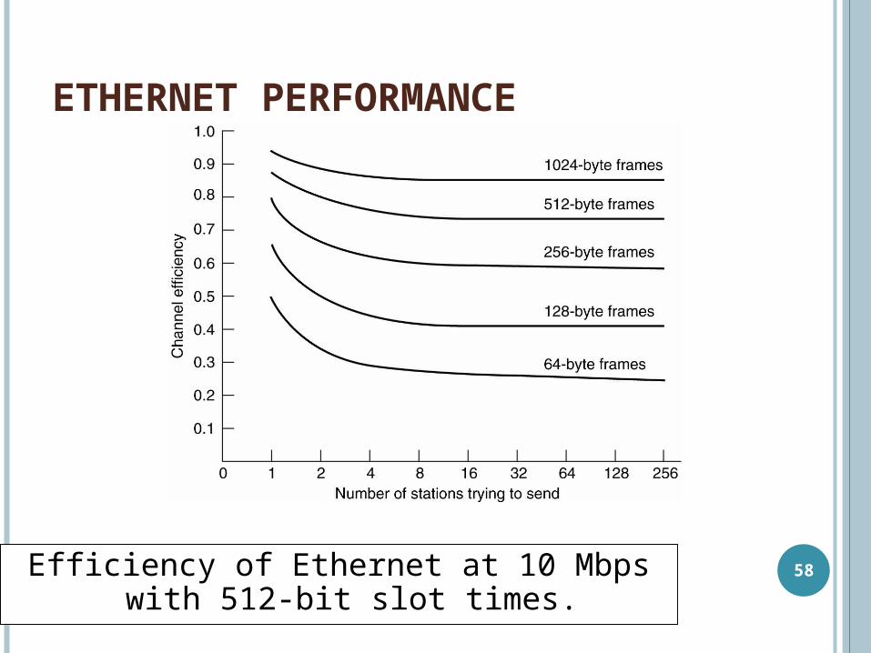
ETHERNET PERFORMANCE
Efficiency of Ethernet at 10 Mbps with 512-bit slot times.
58

13.59
Figure 13.2 HDLC frame compared with LLC and MAC frames

LAN TRANSMISSION TECHNOLOGIES
Ethernet 10 Mbit/s Token Ring 4/16 Mbit/s Fast Ethernet 100 Mbit/s FDDI 100 Mbit/s Gigabit Ethernet 1 Gbit/s ATM 25 Mbit/s to 2.4
Gbit/sOnly Ethernet versions are growing
60